Embed Size (px)
DESCRIPTION
pulsed systems
Citation preview
3 - 1
A Practical Guide to Free-Energy Devices Author: Patrick J. Kelly
Chapter 3: Motionless Pulsed Systems
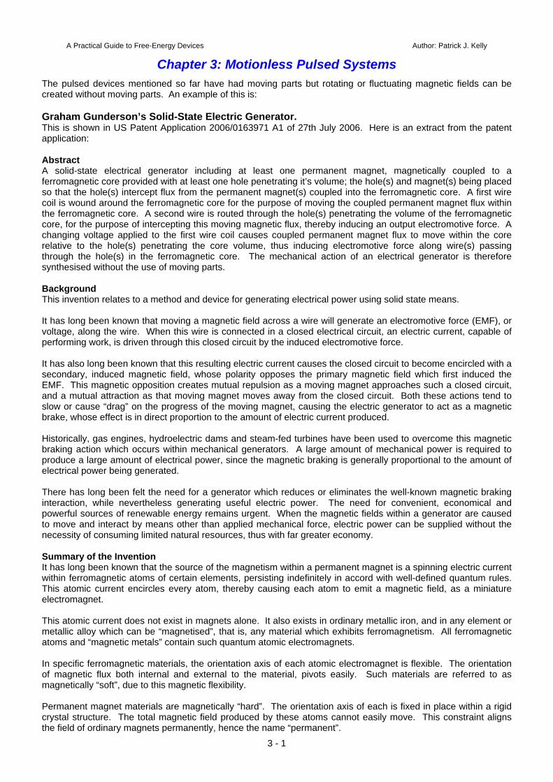
The pulsed devices mentioned so far have had moving parts but rotating or fluctuating magnetic fields can be created without moving parts. An example of this is: Graham Gunderson’s Solid-State Electric Generator. This is shown in US Patent Application 2006/0163971 A1 of 27th July 2006. Here is an extract from the patent application: Abstract A solid-state electrical generator including at least one permanent magnet, magnetically coupled to a ferromagnetic core provided with at least one hole penetrating it’s volume; the hole(s) and magnet(s) being placed so that the hole(s) intercept flux from the permanent magnet(s) coupled into the ferromagnetic core. A first wire coil is wound around the ferromagnetic core for the purpose of moving the coupled permanent magnet flux within the ferromagnetic core. A second wire is routed through the hole(s) penetrating the volume of the ferromagnetic core, for the purpose of intercepting this moving magnetic flux, thereby inducing an output electromotive force. A changing voltage applied to the first wire coil causes coupled permanent magnet flux to move within the core relative to the hole(s) penetrating the core volume, thus inducing electromotive force along wire(s) passing through the hole(s) in the ferromagnetic core. The mechanical action of an electrical generator is therefore synthesised without the use of moving parts. Background This invention relates to a method and device for generating electrical power using solid state means. It has long been known that moving a magnetic field across a wire will generate an electromotive force (EMF), or voltage, along the wire. When this wire is connected in a closed electrical circuit, an electric current, capable of performing work, is driven through this closed circuit by the induced electromotive force. It has also long been known that this resulting electric current causes the closed circuit to become encircled with a secondary, induced magnetic field, whose polarity opposes the primary magnetic field which first induced the EMF. This magnetic opposition creates mutual repulsion as a moving magnet approaches such a closed circuit, and a mutual attraction as that moving magnet moves away from the closed circuit. Both these actions tend to slow or cause “drag” on the progress of the moving magnet, causing the electric generator to act as a magnetic brake, whose effect is in direct proportion to the amount of electric current produced. Historically, gas engines, hydroelectric dams and steam-fed turbines have been used to overcome this magnetic braking action which occurs within mechanical generators. A large amount of mechanical power is required to produce a large amount of electrical power, since the magnetic braking is generally proportional to the amount of electrical power being generated. There has long been felt the need for a generator which reduces or eliminates the well-known magnetic braking interaction, while nevertheless generating useful electric power. The need for convenient, economical and powerful sources of renewable energy remains urgent. When the magnetic fields within a generator are caused to move and interact by means other than applied mechanical force, electric power can be supplied without the necessity of consuming limited natural resources, thus with far greater economy. Summary of the Invention It has long been known that the source of the magnetism within a permanent magnet is a spinning electric current within ferromagnetic atoms of certain elements, persisting indefinitely in accord with well-defined quantum rules. This atomic current encircles every atom, thereby causing each atom to emit a magnetic field, as a miniature electromagnet. This atomic current does not exist in magnets alone. It also exists in ordinary metallic iron, and in any element or metallic alloy which can be “magnetised”, that is, any material which exhibits ferromagnetism. All ferromagnetic atoms and “magnetic metals” contain such quantum atomic electromagnets. In specific ferromagnetic materials, the orientation axis of each atomic electromagnet is flexible. The orientation of magnetic flux both internal and external to the material, pivots easily. Such materials are referred to as magnetically “soft”, due to this magnetic flexibility. Permanent magnet materials are magnetically “hard”. The orientation axis of each is fixed in place within a rigid crystal structure. The total magnetic field produced by these atoms cannot easily move. This constraint aligns the field of ordinary magnets permanently, hence the name “permanent”.
The axis of circular current flow in one ferromagnetic atom can direct the axis of magnetism within another ferromagnetic atom, through a process known as “spin exchange”. This gives a soft magnetic material, like raw iron, the useful ability to aim, focus and redirect the magnetic field emitted from a magnetically hard permanent magnet. In the present invention, a permanent magnet’s rigid field is sent into a magnetically flexible “soft” magnetic material. the permanent magnet’s apparent location, observed from points within the magnetically soft material, will effectively move, vibrate, and appear to shift position when the magnetisation of the soft magnetic material is modulated by ancillary means (much like the sun, viewed while underwater, appears to move when the water is agitated). By this mechanism, the motion required for generation of electricity can be synthesised within a soft magnetic material, without requiring physical movement or an applied mechanical force. The present invention synthesises the virtual motion of magnets and their magnetic fields, without the need for mechanical action or moving parts, to produce the electrical generator described here. The present invention describes an electrical generator where magnetic braking known as expressions of Lenz’s Law, do not oppose the means by which the magnetic field energy is caused to move. The synthesised magnetic motion is produced without either mechanical or electrical resistance. This synthesised magnetic motion is aided by forces generated in accordance with Lenz’s Law, in order to produce acceleration of the synthesised magnetic motion, instead of physical “magnetic braking” common to mechanically-actuated electrical generators. Because of this novel magnetic interaction, the solid-state static generator of the present invention is a robust generator, requiring only a small electric force to operate.
The full patent application is shown in the Appendix. Charles Flynn’s Magnetic Frame. Another device of this type comes from Charles Flynn. The technique of applying magnetic variations to the magnetic flux produced by a permanent magnet is covered in detail in the patents of Charles Flynn which are included in the Appendix. In his patent he shows techniques for producing linear motion, reciprocal motion,
3 - 2
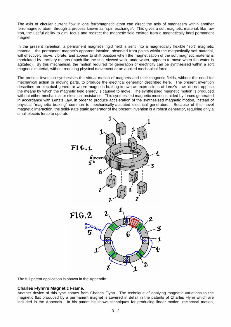
circular motion and power conversion, and he gives a considerable amount of description and explanation on each, his main patent containing a hundred illustrations. Taking one application at random: He states that a substantial enhancement of magnetic flux can be obtained from the use of an arrangement like this:
Here, a laminated soft iron frame has a powerful permanent magnet positioned in it’s centre and six coils are wound in the positions shown. The magnetic flux from the permanent magnet flows around both sides of the frame.
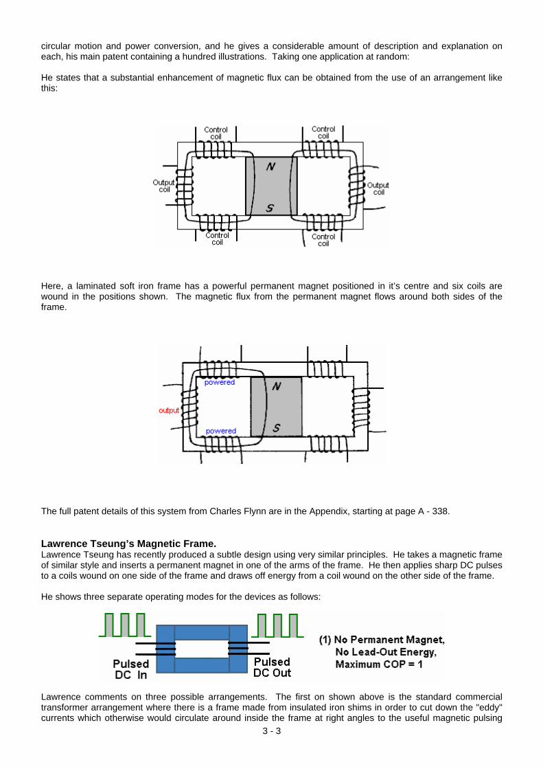
The full patent details of this system from Charles Flynn are in the Appendix, starting at page A - 338. Lawrence Tseung’s Magnetic Frame. Lawrence Tseung has recently produced a subtle design using very similar principles. He takes a magnetic frame of similar style and inserts a permanent magnet in one of the arms of the frame. He then applies sharp DC pulses to a coils wound on one side of the frame and draws off energy from a coil wound on the other side of the frame. He shows three separate operating modes for the devices as follows:
Lawrence comments on three possible arrangements. The first on shown above is the standard commercial transformer arrangement where there is a frame made from insulated iron shims in order to cut down the "eddy" currents which otherwise would circulate around inside the frame at right angles to the useful magnetic pulsing
3 - 3
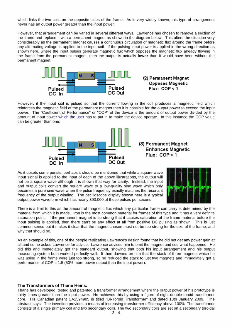
which links the two coils on the opposite sides of the frame. As is very widely known, this type of arrangement never has an output power greater than the input power. However, that arrangement can be varied in several different ways. Lawrence has chosen to remove a section of the frame and replace it with a permanent magnet as shown in the diagram below. This alters the situation very considerably as the permanent magnet causes a continuous circulation of magnetic flux around the frame before any alternating voltage is applied to the input coil. If the pulsing input power is applied in the wrong direction as shown here, where the input pulses generate magnetic flux which opposes the magnetic flux already flowing in the frame from the permanent magnet, then the output is actually lower than it would have been without the permanent magnet.
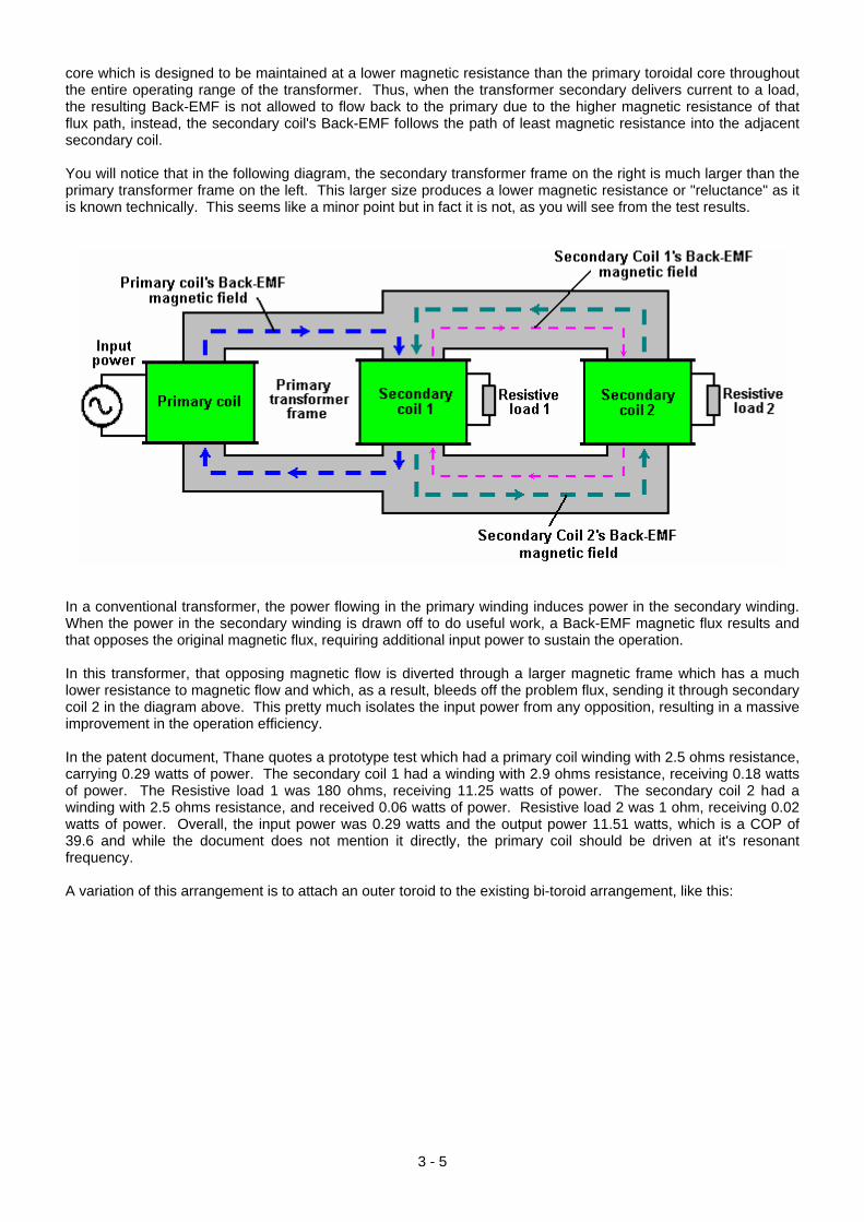
However, if the input coil is pulsed so that the current flowing in the coil produces a magnetic field which reinforces the magnetic field of the permanent magnet then it is possible for the output power to exceed the input power. The "Coefficient of Performance" or "COP" of the device is the amount of output power divided by the amount of input power which the user has to put in to make the device operate. In this instance the COP value can be greater than one:
As it upsets some purists, perhaps it should be mentioned that while a square wave input signal is applied to the input of each of the above illustrations, the output will not be a square wave although it is shown that way for clarity. Instead, the input and output coils convert the square wave to a low-quality sine wave which only becomes a pure sine wave when the pulse frequency exactly matches the resonant frequency of the output winding. The oscilloscope display shown here is a typical output power waveform which has nearly 390,000 of these pulses per second. There is a limit to this as the amount of magnetic flux which any particular frame can carry is determined by the material from which it is made. Iron is the most common material for frames of this type and it has a very definite saturation point. If the permanent magnet is so strong that it causes saturation of the frame material before the input pulsing is applied, then there can't be any effect at all from positive DC pulsing as shown. This is just common sense but it makes it clear that the magnet chosen must not be too strong for the size of the frame, and why that should be. As an example of this, one of the people replicating Lawrence's design found that he did not get any power gain at all and so he asked Lawrence for advice. Lawrence advised him to omit the magnet and see what happened. He did this and immediately got the standard output, showing that both his input arrangement and his output measuring system both worked perfectly well. It then dawned on him that the stack of three magnets which he was using in the frame were just too strong, so he reduced the stack to just two magnets and immediately got a performance of COP = 1.5 (50% more power output than the input power). The Transformers of Thane Heins.
3 - 4
Thane has developed, tested and patented a transformer arrangement where the output power of his prototype is thirty times greater than the input power. He achieves this by using a figure-of-eight double toroid transformer core. His Canadian patent CA2594905 is titled "Bi-Toroid Transformer" and dated 18th January 2009. The abstract says: The invention provides a means of increasing transformer efficiency above 100%. The transformer consists of a single primary coil and two secondary coils. The two secondary coils are set on a secondary toroidal
core which is designed to be maintained at a lower magnetic resistance than the primary toroidal core throughout the entire operating range of the transformer. Thus, when the transformer secondary delivers current to a load, the resulting Back-EMF is not allowed to flow back to the primary due to the higher magnetic resistance of that flux path, instead, the secondary coil's Back-EMF follows the path of least magnetic resistance into the adjacent secondary coil. You will notice that in the following diagram, the secondary transformer frame on the right is much larger than the primary transformer frame on the left. This larger size produces a lower magnetic resistance or "reluctance" as it is known technically. This seems like a minor point but in fact it is not, as you will see from the test results.
In a conventional transformer, the power flowing in the primary winding induces power in the secondary winding. When the power in the secondary winding is drawn off to do useful work, a Back-EMF magnetic flux results and that opposes the original magnetic flux, requiring additional input power to sustain the operation. In this transformer, that opposing magnetic flow is diverted through a larger magnetic frame which has a much lower resistance to magnetic flow and which, as a result, bleeds off the problem flux, sending it through secondary coil 2 in the diagram above. This pretty much isolates the input power from any opposition, resulting in a massive improvement in the operation efficiency. In the patent document, Thane quotes a prototype test which had a primary coil winding with 2.5 ohms resistance, carrying 0.29 watts of power. The secondary coil 1 had a winding with 2.9 ohms resistance, receiving 0.18 watts of power. The Resistive load 1 was 180 ohms, receiving 11.25 watts of power. The secondary coil 2 had a winding with 2.5 ohms resistance, and received 0.06 watts of power. Resistive load 2 was 1 ohm, receiving 0.02 watts of power. Overall, the input power was 0.29 watts and the output power 11.51 watts, which is a COP of 39.6 and while the document does not mention it directly, the primary coil should be driven at it's resonant frequency. A variation of this arrangement is to attach an outer toroid to the existing bi-toroid arrangement, like this:
3 - 5
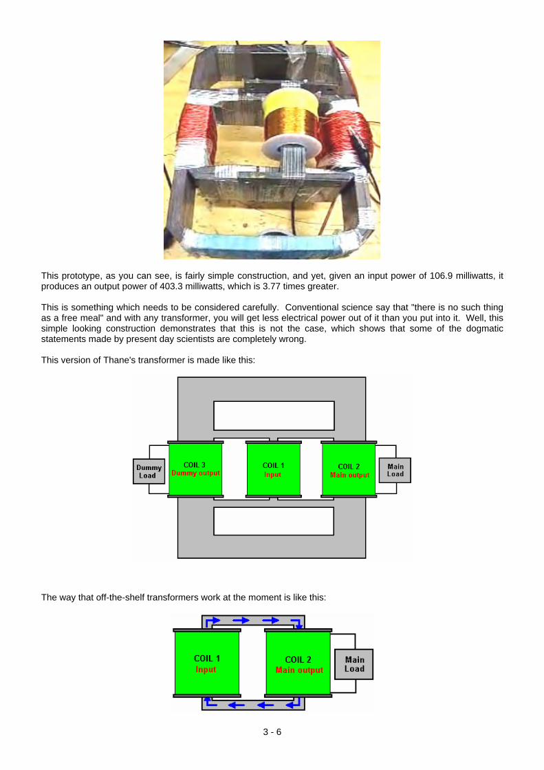
This prototype, as you can see, is fairly simple construction, and yet, given an input power of 106.9 milliwatts, it produces an output power of 403.3 milliwatts, which is 3.77 times greater. This is something which needs to be considered carefully. Conventional science say that "there is no such thing as a free meal" and with any transformer, you will get less electrical power out of it than you put into it. Well, this simple looking construction demonstrates that this is not the case, which shows that some of the dogmatic statements made by present day scientists are completely wrong. This version of Thane's transformer is made like this:
The way that off-the-shelf transformers work at the moment is like this:
3 - 6
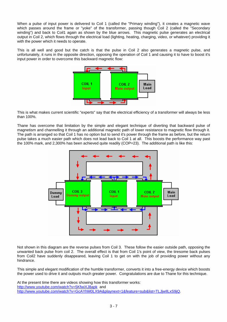
When a pulse of input power is delivered to Coil 1 (called the "Primary winding"), it creates a magnetic wave which passes around the frame or "yoke" of the transformer, passing though Coil 2 (called the "Secondary winding") and back to Coil1 again as shown by the blue arrows. This magnetic pulse generates an electrical output in Coil 2, which flows through the electrical load (lighting, heating, charging, video, or whatever) providing it with the power which it needs to operate. This is all well and good but the catch is that the pulse in Coil 2 also generates a magnetic pulse, and unfortunately, it runs in the opposite direction, opposing the operation of Coil 1 and causing it to have to boost it's input power in order to overcome this backward magnetic flow:
This is what makes current scientific "experts" say that the electrical efficiency of a transformer will always be less than 100%. Thane has overcome that limitation by the simple and elegant technique of diverting that backward pulse of magnetism and channelling it through an additional magnetic path of lower resistance to magnetic flow through it. The path is arranged so that Coil 1 has no option but to send it's power through the frame as before, but the return pulse takes a much easier path which does not lead back to Coil 1 at all. This boosts the performance way past the 100% mark, and 2,300% has been achieved quite readily (COP=23). The additional path is like this:
Not shown in this diagram are the reverse pulses from Coil 3. These follow the easier outside path, opposing the unwanted back pulse from coil 2. The overall effect is that from Coil 1's point of view, the tiresome back pulses from Coil2 have suddenly disappeared, leaving Coil 1 to get on with the job of providing power without any hindrance. This simple and elegant modification of the humble transformer, converts it into a free-energy device which boosts the power used to drive it and outputs much greater power. Congratulations are due to Thane for this technique. At the present time there are videos showing how this transformer works: http://www.youtube.com/watch?v=5KfwiXJ8apk and http://www.youtube.com/watch?v=GcAYhM0LX9A&playnext=1&feature=sub&list=TLJjwIlLxS9jQ.
3 - 7
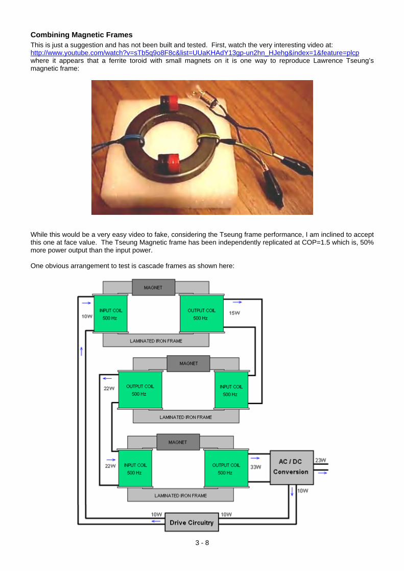
Combining Magnetic Frames This is just a suggestion and has not been built and tested. First, watch the very interesting video at: http://www.youtube.com/watch?v=sTb5q9o8F8c&list=UUaKHAdY13gp-un2hn_HJehg&index=1&feature=plcp where it appears that a ferrite toroid with small magnets on it is one way to reproduce Lawrence Tseung’s magnetic frame:
While this would be a very easy video to fake, considering the Tseung frame performance, I am inclined to accept this one at face value. The Tseung Magnetic frame has been independently replicated at COP=1.5 which is, 50% more power output than the input power. One obvious arrangement to test is cascade frames as shown here:
3 - 8
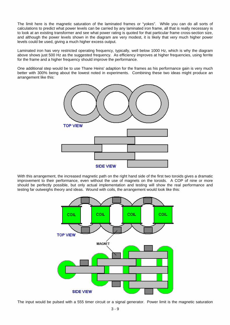
The limit here is the magnetic saturation of the laminated frames or “yokes”. While you can do all sorts of calculations to predict what power levels can be carried by any laminated iron frame, all that is really necessary is to look at an existing transformer and see what power rating is quoted for that particular frame cross-section size, and although the power levels shown in the diagram are very modest, it is likely that very much higher power levels could be used, giving a much higher excess output. Laminated iron has very restricted operating frequency, typically, well below 1000 Hz, which is why the diagram above shows just 500 Hz as the suggested frequency. As efficiency improves at higher frequencies, using ferrite for the frame and a higher frequency should improve the performance. One additional step would be to use Thane Heins' adaption for the frames as his performance gain is very much better with 300% being about the lowest noted in experiments. Combining these two ideas might produce an arrangement like this:
With this arrangement, the increased magnetic path on the right hand side of the first two toroids gives a dramatic improvement to their performance, even without the use of magnets on the toroids. A COP of nine or more should be perfectly possible, but only actual implementation and testing will show the real performance and testing far outweighs theory and ideas. Wound with coils, the arrangement would look like this:
The input would be pulsed with a 555 timer circuit or a signal generator. Power limit is the magnetic saturation
3 - 9
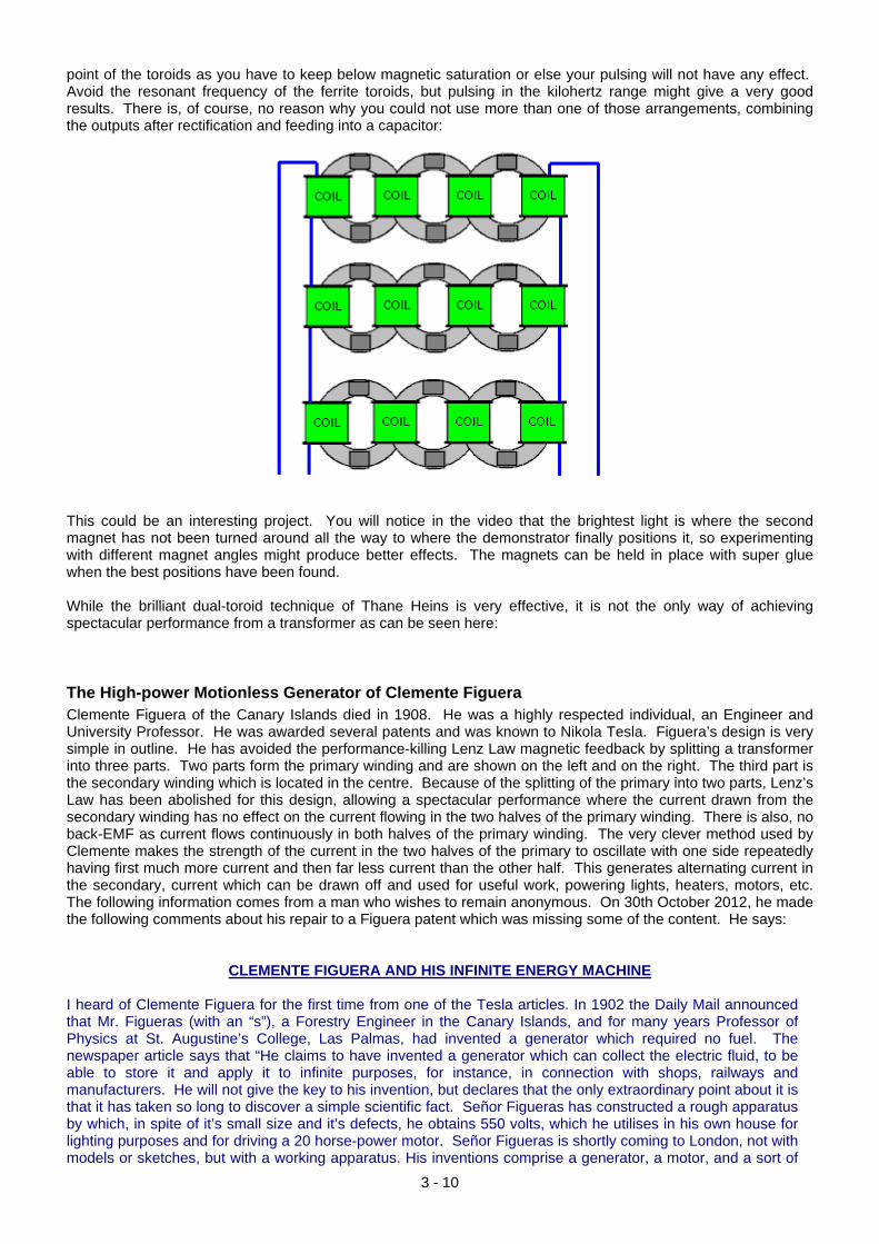
point of the toroids as you have to keep below magnetic saturation or else your pulsing will not have any effect. Avoid the resonant frequency of the ferrite toroids, but pulsing in the kilohertz range might give a very good results. There is, of course, no reason why you could not use more than one of those arrangements, combining the outputs after rectification and feeding into a capacitor:
This could be an interesting project. You will notice in the video that the brightest light is where the second magnet has not been turned around all the way to where the demonstrator finally positions it, so experimenting with different magnet angles might produce better effects. The magnets can be held in place with super glue when the best positions have been found. While the brilliant dual-toroid technique of Thane Heins is very effective, it is not the only way of achieving spectacular performance from a transformer as can be seen here: The High-power Motionless Generator of Clemente Figuera Clemente Figuera of the Canary Islands died in 1908. He was a highly respected individual, an Engineer and University Professor. He was awarded several patents and was known to Nikola Tesla. Figuera’s design is very simple in outline. He has avoided the performance-killing Lenz Law magnetic feedback by splitting a transformer into three parts. Two parts form the primary winding and are shown on the left and on the right. The third part is the secondary winding which is located in the centre. Because of the splitting of the primary into two parts, Lenz’s Law has been abolished for this design, allowing a spectacular performance where the current drawn from the secondary winding has no effect on the current flowing in the two halves of the primary winding. There is also, no back-EMF as current flows continuously in both halves of the primary winding. The very clever method used by Clemente makes the strength of the current in the two halves of the primary to oscillate with one side repeatedly having first much more current and then far less current than the other half. This generates alternating current in the secondary, current which can be drawn off and used for useful work, powering lights, heaters, motors, etc. The following information comes from a man who wishes to remain anonymous. On 30th October 2012, he made the following comments about his repair to a Figuera patent which was missing some of the content. He says:
CLEMENTE FIGUERA AND HIS INFINITE ENERGY MACHINE I heard of Clemente Figuera for the first time from one of the Tesla articles. In 1902 the Daily Mail announced that Mr. Figueras (with an “s”), a Forestry Engineer in the Canary Islands, and for many years Professor of Physics at St. Augustine’s College, Las Palmas, had invented a generator which required no fuel. The newspaper article says that “He claims to have invented a generator which can collect the electric fluid, to be able to store it and apply it to infinite purposes, for instance, in connection with shops, railways and manufacturers. He will not give the key to his invention, but declares that the only extraordinary point about it is that it has taken so long to discover a simple scientific fact. Señor Figueras has constructed a rough apparatus by which, in spite of it’s small size and it’s defects, he obtains 550 volts, which he utilises in his own house for lighting purposes and for driving a 20 horse-power motor. Señor Figueras is shortly coming to London, not with models or sketches, but with a working apparatus. His inventions comprise a generator, a motor, and a sort of
3 - 10
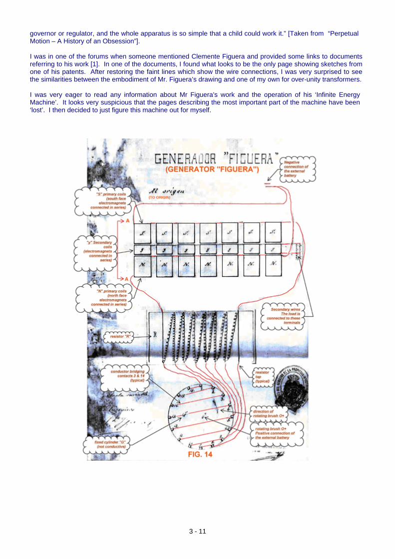
governor or regulator, and the whole apparatus is so simple that a child could work it.” [Taken from “Perpetual Motion – A History of an Obsession”]. I was in one of the forums when someone mentioned Clemente Figuera and provided some links to documents referring to his work [1]. In one of the documents, I found what looks to be the only page showing sketches from one of his patents. After restoring the faint lines which show the wire connections, I was very surprised to see the similarities between the embodiment of Mr. Figuera’s drawing and one of my own for over-unity transformers. I was very eager to read any information about Mr Figuera's work and the operation of his ‘Infinite Energy Machine’. It looks very suspicious that the pages describing the most important part of the machine have been ‘lost’. I then decided to just figure this machine out for myself.
3 - 11
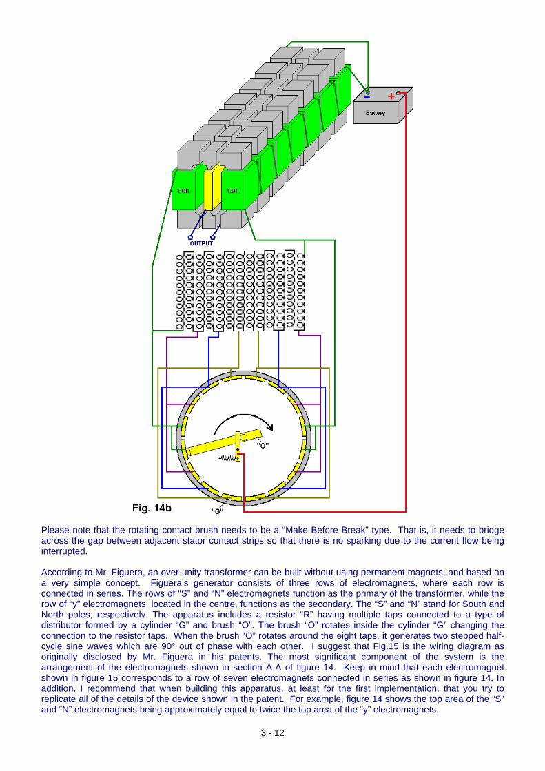
Please note that the rotating contact brush needs to be a “Make Before Break” type. That is, it needs to bridge across the gap between adjacent stator contact strips so that there is no sparking due to the current flow being interrupted. According to Mr. Figuera, an over-unity transformer can be built without using permanent magnets, and based on a very simple concept. Figuera’s generator consists of three rows of electromagnets, where each row is connected in series. The rows of “S” and “N” electromagnets function as the primary of the transformer, while the row of “y” electromagnets, located in the centre, functions as the secondary. The “S” and “N” stand for South and North poles, respectively. The apparatus includes a resistor “R” having multiple taps connected to a type of distributor formed by a cylinder “G” and brush “O”. The brush “O” rotates inside the cylinder “G” changing the connection to the resistor taps. When the brush “O” rotates around the eight taps, it generates two stepped half-cycle sine waves which are 90° out of phase with each other. I suggest that Fig.15 is the wiring diagram as originally disclosed by Mr. Figuera in his patents. The most significant component of the system is the arrangement of the electromagnets shown in section A-A of figure 14. Keep in mind that each electromagnet shown in figure 15 corresponds to a row of seven electromagnets connected in series as shown in figure 14. In addition, I recommend that when building this apparatus, at least for the first implementation, that you try to replicate all of the details of the device shown in the patent. For example, figure 14 shows the top area of the “S” and “N” electromagnets being approximately equal to twice the top area of the “y” electromagnets.
3 - 12
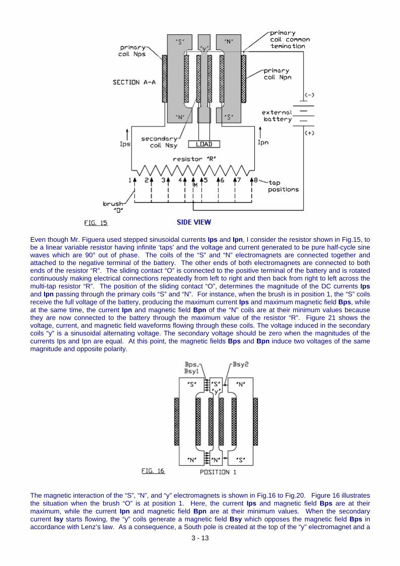
Even though Mr. Figuera used stepped sinusoidal currents Ips and Ipn, I consider the resistor shown in Fig.15, to be a linear variable resistor having infinite ‘taps’ and the voltage and current generated to be pure half-cycle sine waves which are 90° out of phase. The coils of the “S” and “N” electromagnets are connected together and attached to the negative terminal of the battery. The other ends of both electromagnets are connected to both ends of the resistor “R”. The sliding contact “O” is connected to the positive terminal of the battery and is rotated continuously making electrical connections repeatedly from left to right and then back from right to left across the multi-tap resistor “R”. The position of the sliding contact “O”, determines the magnitude of the DC currents Ips and Ipn passing through the primary coils “S” and “N”. For instance, when the brush is in position 1, the “S” coils receive the full voltage of the battery, producing the maximum current Ips and maximum magnetic field Bps, while at the same time, the current Ipn and magnetic field Bpn of the “N” coils are at their minimum values because they are now connected to the battery through the maximum value of the resistor “R”. Figure 21 shows the voltage, current, and magnetic field waveforms flowing through these coils. The voltage induced in the secondary coils “y” is a sinusoidal alternating voltage. The secondary voltage should be zero when the magnitudes of the currents Ips and Ipn are equal. At this point, the magnetic fields Bps and Bpn induce two voltages of the same magnitude and opposite polarity.
The magnetic interaction of the “S”, “N”, and “y” electromagnets is shown in Fig.16 to Fig.20. Figure 16 illustrates the situation when the brush “O” is at position 1. Here, the current Ips and magnetic field Bps are at their maximum, while the current Ipn and magnetic field Bpn are at their minimum values. When the secondary current Isy starts flowing, the “y” coils generate a magnetic field Bsy which opposes the magnetic field Bps in accordance with Lenz’s law. As a consequence, a South pole is created at the top of the “y” electromagnet and a
3 - 13
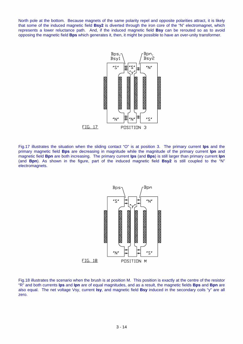
North pole at the bottom. Because magnets of the same polarity repel and opposite polarities attract, it is likely that some of the induced magnetic field Bsy2 is diverted through the iron core of the “N” electromagnet, which represents a lower reluctance path. And, if the induced magnetic field Bsy can be rerouted so as to avoid opposing the magnetic field Bps which generates it, then, it might be possible to have an over-unity transformer.
Fig.17 illustrates the situation when the sliding contact “O” is at position 3. The primary current Ips and the primary magnetic field Bps are decreasing in magnitude while the magnitude of the primary current Ipn and magnetic field Bpn are both increasing. The primary current Ips (and Bps) is still larger than primary current Ipn (and Bpn). As shown in the figure, part of the induced magnetic field Bsy2 is still coupled to the “N” electromagnets.
Fig.18 illustrates the scenario when the brush is at position M. This position is exactly at the centre of the resistor “R” and both currents Ips and Ipn are of equal magnitudes, and as a result, the magnetic fields Bps and Bpn are also equal. The net voltage Vsy, current Isy, and magnetic field Bsy induced in the secondary coils “y” are all zero.
3 - 14
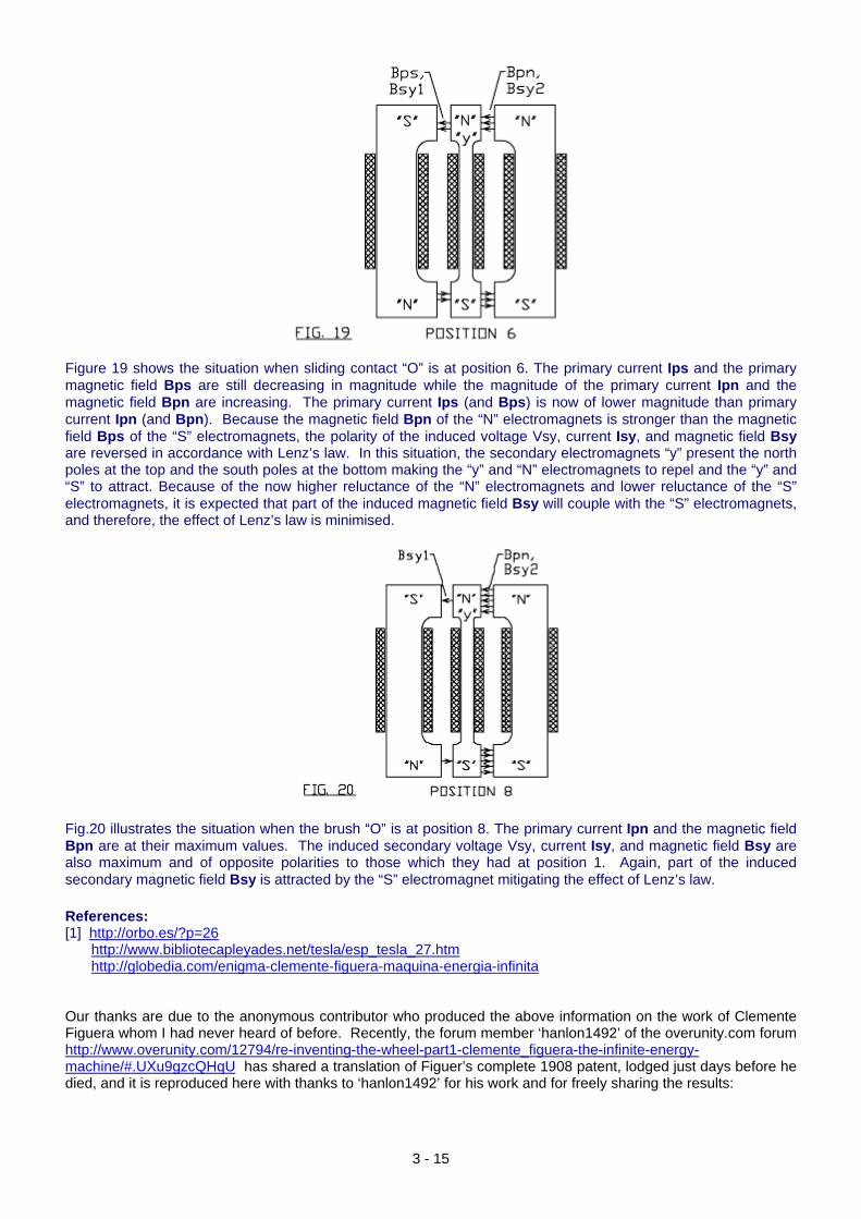
Figure 19 shows the situation when sliding contact “O” is at position 6. The primary current Ips and the primary magnetic field Bps are still decreasing in magnitude while the magnitude of the primary current Ipn and the magnetic field Bpn are increasing. The primary current Ips (and Bps) is now of lower magnitude than primary current Ipn (and Bpn). Because the magnetic field Bpn of the “N” electromagnets is stronger than the magnetic field Bps of the “S” electromagnets, the polarity of the induced voltage Vsy, current Isy, and magnetic field Bsy are reversed in accordance with Lenz’s law. In this situation, the secondary electromagnets “y” present the north poles at the top and the south poles at the bottom making the “y” and “N” electromagnets to repel and the “y” and “S” to attract. Because of the now higher reluctance of the “N” electromagnets and lower reluctance of the “S” electromagnets, it is expected that part of the induced magnetic field Bsy will couple with the “S” electromagnets, and therefore, the effect of Lenz’s law is minimised.
Fig.20 illustrates the situation when the brush “O” is at position 8. The primary current Ipn and the magnetic field Bpn are at their maximum values. The induced secondary voltage Vsy, current Isy, and magnetic field Bsy are also maximum and of opposite polarities to those which they had at position 1. Again, part of the induced secondary magnetic field Bsy is attracted by the “S” electromagnet mitigating the effect of Lenz’s law. References: [1] http://orbo.es/?p=26
http://www.bibliotecapleyades.net/tesla/esp_tesla_27.htmhttp://globedia.com/enigma-clemente-figuera-maquina-energia-infinita
Our thanks are due to the anonymous contributor who produced the above information on the work of Clemente Figuera whom I had never heard of before. Recently, the forum member ‘hanlon1492’ of the overunity.com forum http://www.overunity.com/12794/re-inventing-the-wheel-part1-clemente_figuera-the-infinite-energy-machine/#.UXu9gzcQHqU has shared a translation of Figuer’s complete 1908 patent, lodged just days before he died, and it is reproduced here with thanks to ‘hanlon1492’ for his work and for freely sharing the results:
3 - 15
3 - 16
PATENT by CLEMENTE FIGUERA (year 1908) No. 44267 (Spain) Ministry of Development General Board of Agriculture, Industry and Commerce. Patents of Invention. Expired. Dossier number 44267. Instruction at the request of D. Clemente Figuera. Representative Mr. Buforn. Presented in the register of the Ministry in the 31st October 1908, at 11:55 received in the negotiated in the 2nd November 1908.
ELECTRICAL GENERATOR “FIGUERA” BACKGROUND If we rotate a closed circuit inside a spinning magnetic field, with the closed circuit positioned at right angles to the lines of magnetic force, a current will be induced in the closed circuit for as long as there is movement, and the sign of that induced current will depend on the direction in which the closed circuit moves. This is the basis of all magnetic machines and electric dynamos from the original, invented by Pixii, in France and later modified and improved by Clarke to reach the design of the current dynamos of today. The principle on which this theory is based, has the unavoidable need for the movement of either the induction circuit or the magnetic circuit, and so, these machines are considered to be a transformer of mechanical work into electricity. PRINCIPLE OF THE INVENTION Considering carefully what happens in a dynamo in motion, we see that the coil turns of the induction circuit approach and move away from the magnetic centres of the magnets or electromagnets, and those turns, while spinning, pass through sections of the magnetic field of different magnetic strengths, because, while the maximum magnetic strength is in the centre of the core of each electromagnet, this action weakens as the induction coil moves away from the centre of the electromagnet, only to increase again when it is approaching the centre of another electromagnet with opposite sign to the first one. Because we all know that the effects seen when a closed circuit approaches and moves away from a magnetic centre are the same as when the circuit is motionless and the magnetic field increased and decreased in intensity, since any variation of the magnetic flow traversing a circuit produces an induced electrical current. Then, consideration was given to the possibility of building a machine which would work, based, not on the principle of movement as current dynamos do, but based on the principle of increasing and decreasing the strength of the magnetic field, or the strength of the electrical current which produces it. The voltage from the total current of the current dynamos is the sum of all of the induced currents generated in every turn of the induction coils. Therefore it does not matter if these induced currents were generated by rotating the induction coils, or by varying the magnetic flux which passes through them. In the first case, a greater amount of mechanical work is required than the amount of electricity generated, while in the second case, the force needed to produce the variation of magnetic flux is so insignificant that it can easily be taken from the output generated by the machine. Up to the present day, no machine based on this principle has been constructed for the production of large electrical currents, and which among other advantages, has overcome the necessity for motion and so, the energy needed to produce it. In order to attain the production of large industrial electrical currents, using the principle that electrical current can be provided by just changing the flow of magnetic flux through an induction circuit, the above disclosure should be sufficient, however, as this operating principle needs to embodied in a practical machine, there is a need to describe it in order to fully disclose how to carry out a practical application of this principle. This principle is not new since it is just a consequence of the laws of induction stated by Faraday in the year 1831: what it is new and claimed in this patent, is the application of this principle to a machine which produces large industrial electrical currents and which, up to now, has only been obtained by transforming mechanical work into electricity. We will therefore, provide a description of a machine based on the above principle disclosed in this patent; but it must be understood, and what is sought is the patent for the application of this principle, that all machines built based on this principle, will be included in the scope of this patent, whatever the form and way that has been used to make the application.
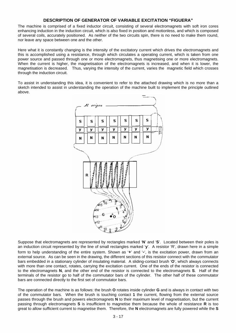
DESCRIPTION OF GENERATOR OF VARIABLE EXCITATION “FIGUERA” The machine is comprised of a fixed inductor circuit, consisting of several electromagnets with soft iron cores enhancing induction in the induction circuit, which is also fixed in position and motionless, and which is composed of several coils, accurately positioned. As neither of the two circuits spin, there is no need to make them round, nor leave any space between one and the other. Here what it is constantly changing is the intensity of the excitatory current which drives the electromagnets and this is accomplished using a resistance, through which circulates a operating current, which is taken from one power source and passed through one or more electromagnets, thus magnetising one or more electromagnets. When the current is higher, the magnetisation of the electromagnets is increased, and when it is lower, the magnetisation is decreased. Thus, varying the intensity of the current, varies the magnetic field which crosses through the induction circuit. To assist in understanding this idea, it is convenient to refer to the attached drawing which is no more than a sketch intended to assist in understanding the operation of the machine built to implement the principle outlined above.
Suppose that electromagnets are represented by rectangles marked ‘N’ and ‘S’. Located between their poles is an induction circuit represented by the line of small rectangles marked ‘y’. A resistor ‘R’, drawn here in a simple form to help understanding of the entire system. Shown as ‘+’ and ‘-‘, is the excitation power, drawn from an external source. As can be seen in the drawing, the different sections of this resistor connect with the commutator bars embedded in a stationary cylinder of insulating material. A sliding-contact brush ‘O’, which always connects with more than one contact, rotates, carrying the excitation current. One of the ends of the resistor is connected to the electromagnets N, and the other end of the resistor is connected to the electromagnets S. Half of the terminals of the resistor go to half of the commutator bars of the cylinder. The other half of these commutator bars are connected directly to the first set of commutator bars. The operation of the machine is as follows: the brush O rotates inside cylinder G and is always in contact with two of the commutator bars. When the brush is touching contact 1 the current, flowing from the external source passes through the brush and powers electromagnets N to their maximum level of magnetisation, but the current passing through electromagnets S is insufficient to magnetise them because the whole of resistance R is too great to allow sufficient current to magnetise them. Therefore, the N electromagnets are fully powered while the S
3 - 17
3 - 18
electromagnets are not sufficiently powered to be magnetised. When the brush connects with contact 2, the whole of the current will not flow through electromagnets N because it has to pass through part of the resistor. Consequently, some current will pass through the electromagnets S because it has to overcome less resistance than in the previous case. This same reasoning applies to the case when brush O connects with each of the different contacts around the first semicircle. Then the brush O starts to connect with the commutator contacts in the other half, each of which are directly connected to their corresponding commutator contacts in the first half. In short, the resistor has the function of a current-splitter, powering either one set of electromagnets or the other set of electromagnets repeatedly. It can be seen that electromagnet sets N and S operate in a complementary manner, because while the first set is being progressively powered up, the other set is being progressively powered down. This sequence is repeated continuously causing an orderly a constant variation of the magnetic fields passing through the induction circuit. This action can be maintained by just the simple rotation of a brush or group of brushes which rotate in a circle inside cylinder G driven by a small electric motor. As indicated by the drawing the current, once it has flowed through the electromagnets, returns to the power source where it originated. A small part of the output current from this device can be used to provide the ‘external’ excitation power mentioned above, thus making the machine self-exciting and to provide the current to operate the small motor which moves the brush causing the switching. Once started with an external power source, that external power source can be removed and the machine will continue to work indefinitely without any external power source. This invention is really new, very daring, and above all, has huge technical and industrial consequences in all areas. This patent was not applied for until a working machine based on these principles had been built, thus proving the concept to be sound and practical.
ADVANTAGES OF THE ELECTRICAL GENERATOR “FIGUERA” 1. The completely free production of DC or AC electric current of any voltage which can be used for:
a. Providing a driving force. b. Production of light. c. Production of heat. d. All other existing uses of electricity.
2. There is no need whatsoever for a driving force of any kind or chemical reactions or fuel consumption. 3. Needs little or no lubrication. 4. Is so simple that it can be easily operated by anyone. 5. Does not produce smoke, noise, or vibration when operating. 6. Indefinite operational life. 7. Has a wide range of uses: home management and industrial. 8. Easy construction. 9. Cheap to produce and market NOTE A 20-year patent is requested for a “NEW GENERATOR OF ELECTRICITY, so-called “FIGUERA” of variable excitation, designed to produce electrical currents for industrial applications without using either driving force, nor chemical reactions. The machine is essentially characterised by two series of electromagnets which form the inductor circuit, between whose poles induction coils are placed. Both the induction and inductor circuits remain motionless and yet are able to produce a current induced by the constant variation of the intensity of the magnetic field forcing the excitatory current (coming at first from any external source) to pass through a rotating brush which, in its rotation movement, connects with the commutator bars or contacts of a ring distributor or cylinder whose contacts are connected to a resistor whose value varies from a maximum to a minimum and vice versa, according with the commutator bars of the cylinder which operates, and for that reason the resistance is connected to the electromagnets N by one of its side, and the electromagnets S at the other side, in such a way that the excitatory current will be magnetising successively with more or less strength, the first electromagnets, while, simultaneously decreasing or increasing the magnetisation in the second set, determining these variations
in intensity of the magnetic field, the production of the current in the induced, current that we can use for any work for the most part, and of which only one small fraction is derived for the actuation of a small electrical motor which rotates the brush, and another fraction goes to the continuous excitation of the electromagnets, and, therefore, converting the machine to become self-exciting, being able to remove the external power which was used initially to excite the electromagnets. Once the machinery is in motion, no new force is required and the machine will continue in operation indefinitely. All in accordance with the described and detailed in this report and as represented in the drawings which are attached. Barcelona, the 30th of October, 1908. Signed: Constantino de Buforn.
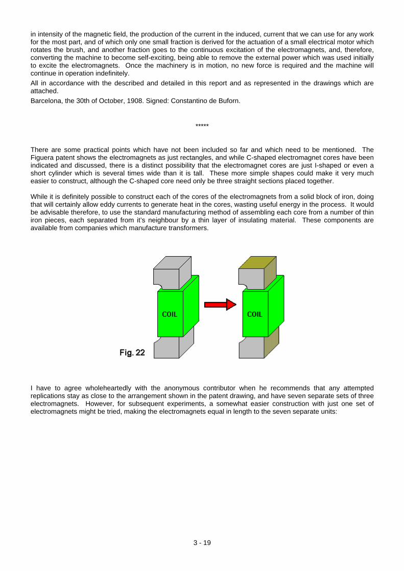
***** There are some practical points which have not been included so far and which need to be mentioned. The Figuera patent shows the electromagnets as just rectangles, and while C-shaped electromagnet cores have been indicated and discussed, there is a distinct possibility that the electromagnet cores are just I-shaped or even a short cylinder which is several times wide than it is tall. These more simple shapes could make it very much easier to construct, although the C-shaped core need only be three straight sections placed together. While it is definitely possible to construct each of the cores of the electromagnets from a solid block of iron, doing that will certainly allow eddy currents to generate heat in the cores, wasting useful energy in the process. It would be advisable therefore, to use the standard manufacturing method of assembling each core from a number of thin iron pieces, each separated from it’s neighbour by a thin layer of insulating material. These components are available from companies which manufacture transformers.
I have to agree wholeheartedly with the anonymous contributor when he recommends that any attempted replications stay as close to the arrangement shown in the patent drawing, and have seven separate sets of three electromagnets. However, for subsequent experiments, a somewhat easier construction with just one set of electromagnets might be tried, making the electromagnets equal in length to the seven separate units:
3 - 19
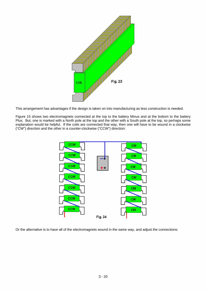
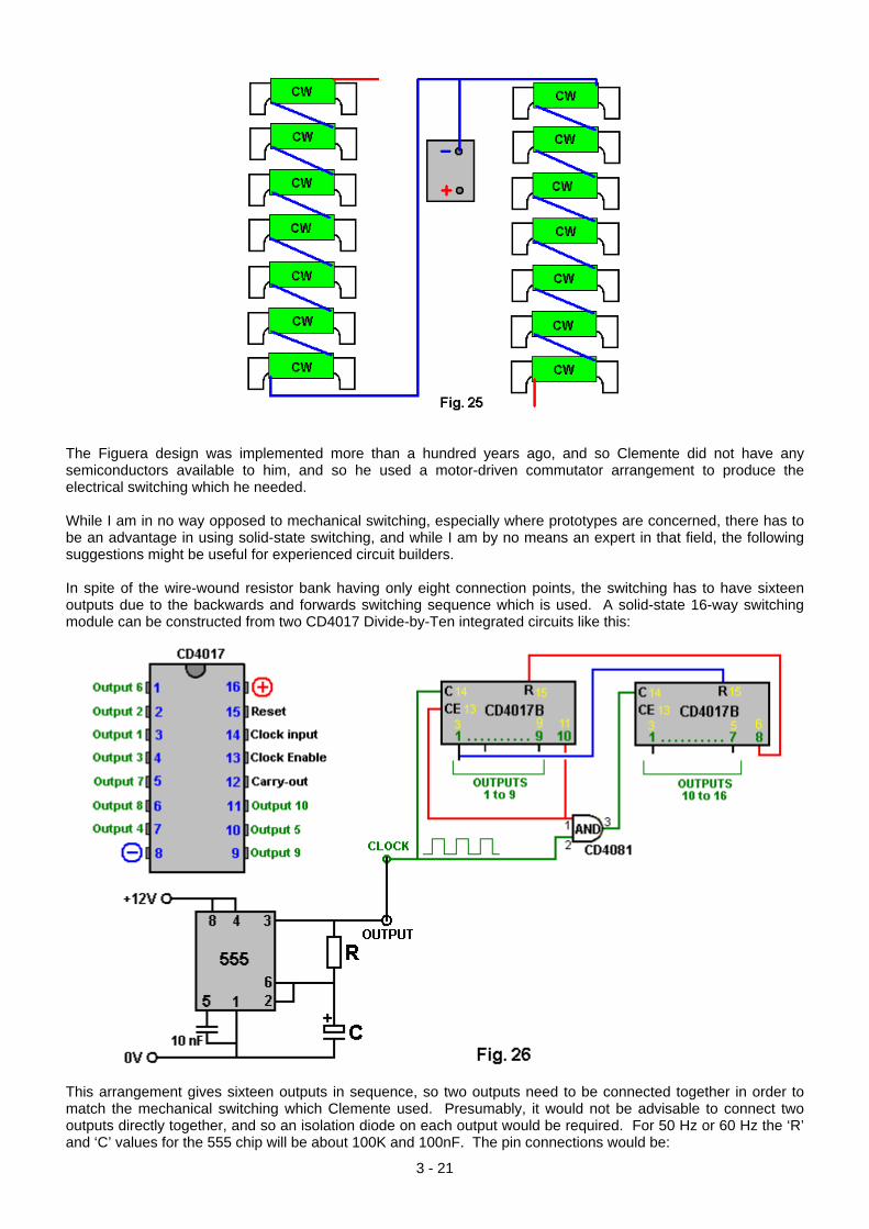
This arrangement has advantages if the design is taken on into manufacturing as less construction is needed. Figure 15 shows two electromagnets connected at the top to the battery Minus and at the bottom to the battery Plus. But, one is marked with a North pole at the top and the other with a South pole at the top, so perhaps some explanation would be helpful. If the coils are connected that way, then one will have to be wound in a clockwise (“CW”) direction and the other in a counter-clockwise (“CCW”) direction:
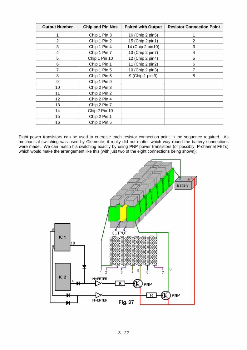
Or the alternative is to have all of the electromagnets wound in the same way, and adjust the connections:
3 - 20
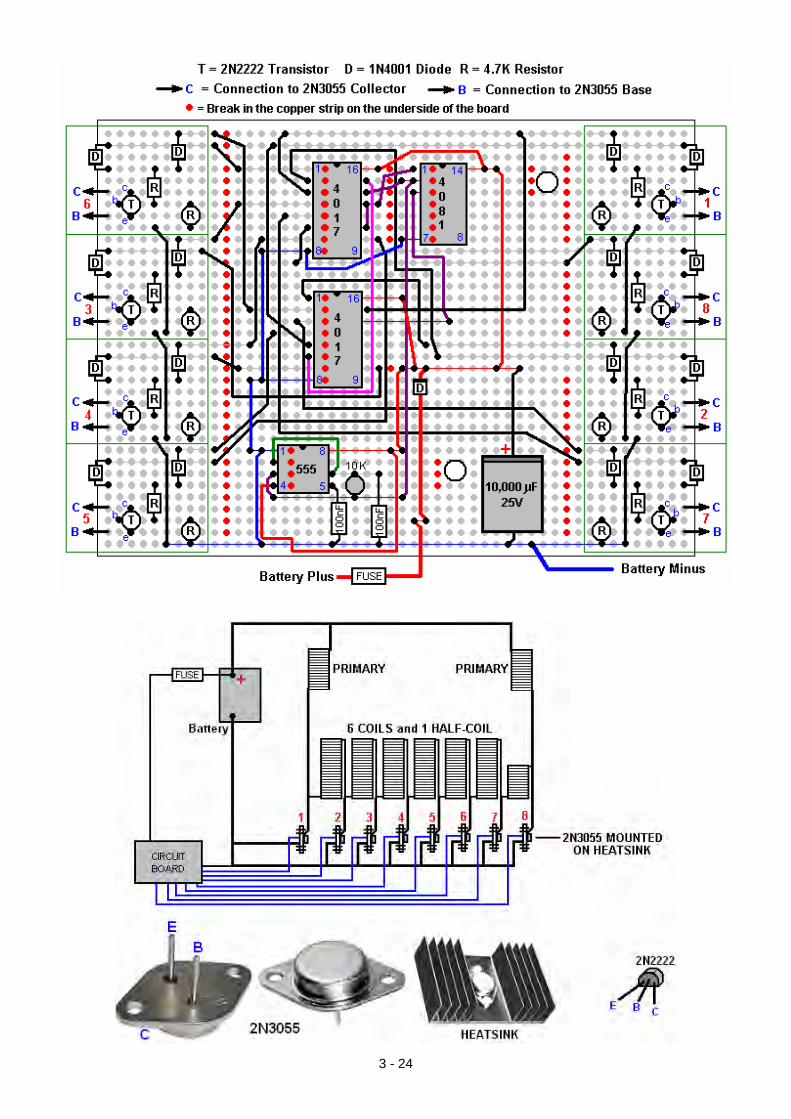
The Figuera design was implemented more than a hundred years ago, and so Clemente did not have any semiconductors available to him, and so he used a motor-driven commutator arrangement to produce the electrical switching which he needed. While I am in no way opposed to mechanical switching, especially where prototypes are concerned, there has to be an advantage in using solid-state switching, and while I am by no means an expert in that field, the following suggestions might be useful for experienced circuit builders. In spite of the wire-wound resistor bank having only eight connection points, the switching has to have sixteen outputs due to the backwards and forwards switching sequence which is used. A solid-state 16-way switching module can be constructed from two CD4017 Divide-by-Ten integrated circuits like this:
This arrangement gives sixteen outputs in sequence, so two outputs need to be connected together in order to match the mechanical switching which Clemente used. Presumably, it would not be advisable to connect two outputs directly together, and so an isolation diode on each output would be required. For 50 Hz or 60 Hz the ‘R’ and ‘C’ values for the 555 chip will be about 100K and 100nF. The pin connections would be:
3 - 21
Output Number Chip and Pin Nos Paired with Output Resistor Connection Point
1 Chip 1 Pin 3 16 (Chip 2 pin5) 1 2 Chip 1 Pin 2 15 (Chip 2 pin1) 2 3 Chip 1 Pin 4 14 (Chip 2 pin10) 3 4 Chip 1 Pin 7 13 (Chip 2 pin7) 4 5 Chip 1 Pin 10 12 (Chip 2 pin4) 5 6 Chip 1 Pin 1 11 (Chip 2 pin2) 6 7 Chip 1 Pin 5 10 (Chip 2 pin3) 7 8 Chip 1 Pin 6 9 (Chip 1 pin 9) 8 9 Chip 1 Pin 9 10 Chip 2 Pin 3 11 Chip 2 Pin 2 12 Chip 2 Pin 4 13 Chip 2 Pin 7 14 Chip 2 Pin 10 15 Chip 2 Pin 1 16 Chip 2 Pin 5
Eight power transistors can be used to energise each resistor connection point in the sequence required. As mechanical switching was used by Clemente, it really did not matter which way round the battery connections were made. We can match his switching exactly by using PNP power transistors (or possibly, P-channel FETs) which would make the arrangement like this (with just two of the eight connections being shown):
3 - 22
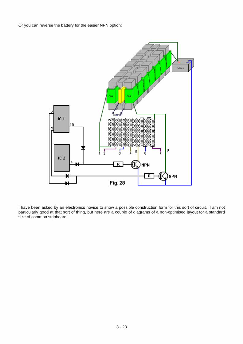
Or you can reverse the battery for the easier NPN option:
I have been asked by an electronics novice to show a possible construction form for this sort of circuit. I am not particularly good at that sort of thing, but here are a couple of diagrams of a non-optimised layout for a standard size of common stripboard:
3 - 23
3 - 24
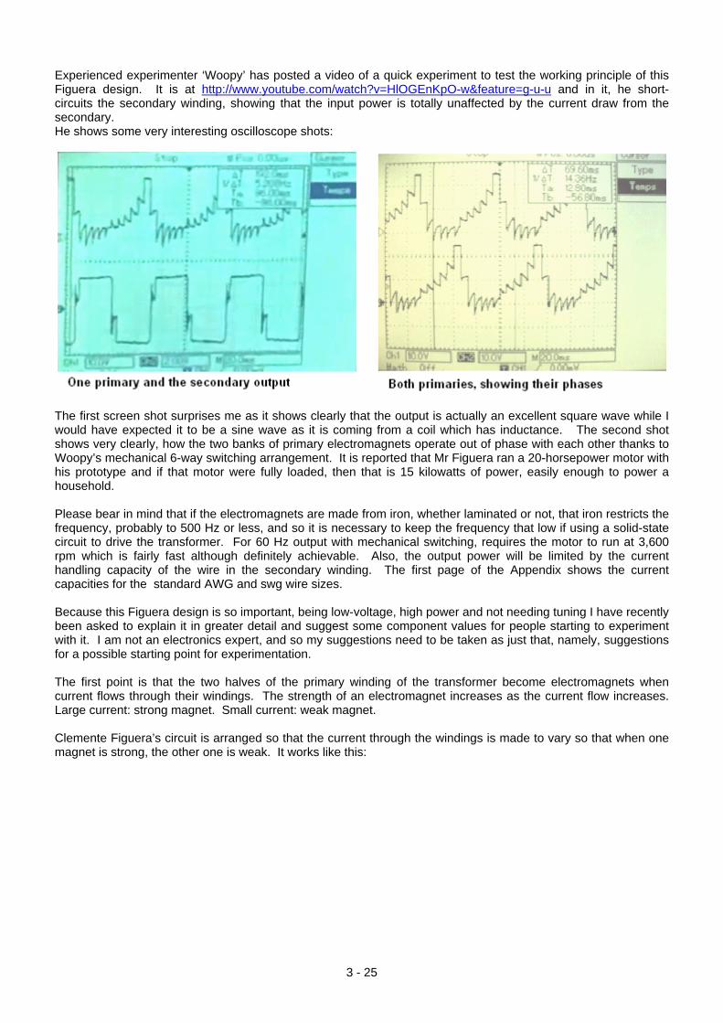
Experienced experimenter ‘Woopy’ has posted a video of a quick experiment to test the working principle of this Figuera design. It is at http://www.youtube.com/watch?v=HlOGEnKpO-w&feature=g-u-u and in it, he short-circuits the secondary winding, showing that the input power is totally unaffected by the current draw from the secondary. He shows some very interesting oscilloscope shots:
The first screen shot surprises me as it shows clearly that the output is actually an excellent square wave while I would have expected it to be a sine wave as it is coming from a coil which has inductance. The second shot shows very clearly, how the two banks of primary electromagnets operate out of phase with each other thanks to Woopy’s mechanical 6-way switching arrangement. It is reported that Mr Figuera ran a 20-horsepower motor with his prototype and if that motor were fully loaded, then that is 15 kilowatts of power, easily enough to power a household. Please bear in mind that if the electromagnets are made from iron, whether laminated or not, that iron restricts the frequency, probably to 500 Hz or less, and so it is necessary to keep the frequency that low if using a solid-state circuit to drive the transformer. For 60 Hz output with mechanical switching, requires the motor to run at 3,600 rpm which is fairly fast although definitely achievable. Also, the output power will be limited by the current handling capacity of the wire in the secondary winding. The first page of the Appendix shows the current capacities for the standard AWG and swg wire sizes. Because this Figuera design is so important, being low-voltage, high power and not needing tuning I have recently been asked to explain it in greater detail and suggest some component values for people starting to experiment with it. I am not an electronics expert, and so my suggestions need to be taken as just that, namely, suggestions for a possible starting point for experimentation. The first point is that the two halves of the primary winding of the transformer become electromagnets when current flows through their windings. The strength of an electromagnet increases as the current flow increases. Large current: strong magnet. Small current: weak magnet. Clemente Figuera’s circuit is arranged so that the current through the windings is made to vary so that when one magnet is strong, the other one is weak. It works like this:
3 - 25
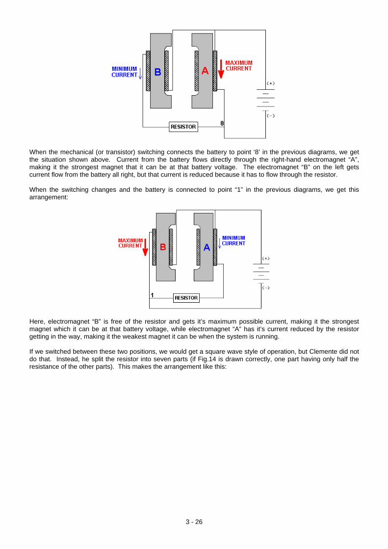
When the mechanical (or transistor) switching connects the battery to point ‘8’ in the previous diagrams, we get the situation shown above. Current from the battery flows directly through the right-hand electromagnet “A”, making it the strongest magnet that it can be at that battery voltage. The electromagnet “B” on the left gets current flow from the battery all right, but that current is reduced because it has to flow through the resistor. When the switching changes and the battery is connected to point “1” in the previous diagrams, we get this arrangement:
Here, electromagnet “B” is free of the resistor and gets it’s maximum possible current, making it the strongest magnet which it can be at that battery voltage, while electromagnet “A” has it’s current reduced by the resistor getting in the way, making it the weakest magnet it can be when the system is running. If we switched between these two positions, we would get a square wave style of operation, but Clemente did not do that. Instead, he split the resistor into seven parts (if Fig.14 is drawn correctly, one part having only half the resistance of the other parts). This makes the arrangement like this:
3 - 26
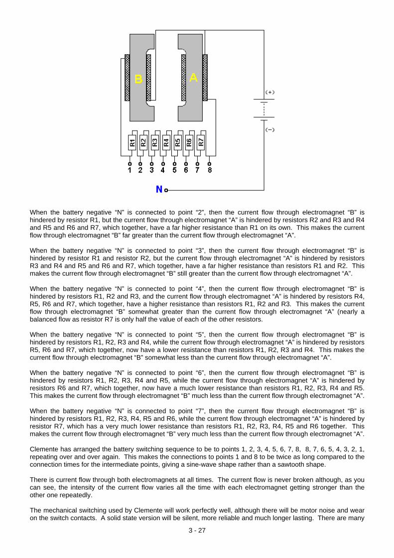
When the battery negative “N” is connected to point “2”, then the current flow through electromagnet “B” is hindered by resistor R1, but the current flow through electromagnet “A” is hindered by resistors R2 and R3 and R4 and R5 and R6 and R7, which together, have a far higher resistance than R1 on its own. This makes the current flow through electromagnet “B” far greater than the current flow through electromagnet “A”. When the battery negative “N” is connected to point “3”, then the current flow through electromagnet “B” is hindered by resistor R1 and resistor R2, but the current flow through electromagnet “A” is hindered by resistors R3 and R4 and R5 and R6 and R7, which together, have a far higher resistance than resistors R1 and R2. This makes the current flow through electromagnet “B” still greater than the current flow through electromagnet “A”. When the battery negative “N” is connected to point “4”, then the current flow through electromagnet “B” is hindered by resistors R1, R2 and R3, and the current flow through electromagnet “A” is hindered by resistors R4, R5, R6 and R7, which together, have a higher resistance than resistors R1, R2 and R3. This makes the current flow through electromagnet “B” somewhat greater than the current flow through electromagnet “A” (nearly a balanced flow as resistor R7 is only half the value of each of the other resistors. When the battery negative “N” is connected to point “5”, then the current flow through electromagnet “B” is hindered by resistors R1, R2, R3 and R4, while the current flow through electromagnet “A” is hindered by resistors R5, R6 and R7, which together, now have a lower resistance than resistors R1, R2, R3 and R4. This makes the current flow through electromagnet “B” somewhat less than the current flow through electromagnet “A”. When the battery negative “N” is connected to point “6”, then the current flow through electromagnet “B” is hindered by resistors R1, R2, R3, R4 and R5, while the current flow through electromagnet “A” is hindered by resistors R6 and R7, which together, now have a much lower resistance than resistors R1, R2, R3, R4 and R5. This makes the current flow through electromagnet “B” much less than the current flow through electromagnet “A”. When the battery negative “N” is connected to point “7”, then the current flow through electromagnet “B” is hindered by resistors R1, R2, R3, R4, R5 and R6, while the current flow through electromagnet “A” is hindered by resistor R7, which has a very much lower resistance than resistors R1, R2, R3, R4, R5 and R6 together. This makes the current flow through electromagnet “B” very much less than the current flow through electromagnet “A”. Clemente has arranged the battery switching sequence to be to points 1, 2, 3, 4, 5, 6, 7, 8, 8, 7, 6, 5, 4, 3, 2, 1, repeating over and over again. This makes the connections to points 1 and 8 to be twice as long compared to the connection times for the intermediate points, giving a sine-wave shape rather than a sawtooth shape. There is current flow through both electromagnets at all times. The current flow is never broken although, as you can see, the intensity of the current flow varies all the time with each electromagnet getting stronger than the other one repeatedly. The mechanical switching used by Clemente will work perfectly well, although there will be motor noise and wear on the switch contacts. A solid state version will be silent, more reliable and much longer lasting. There are many
3 - 27
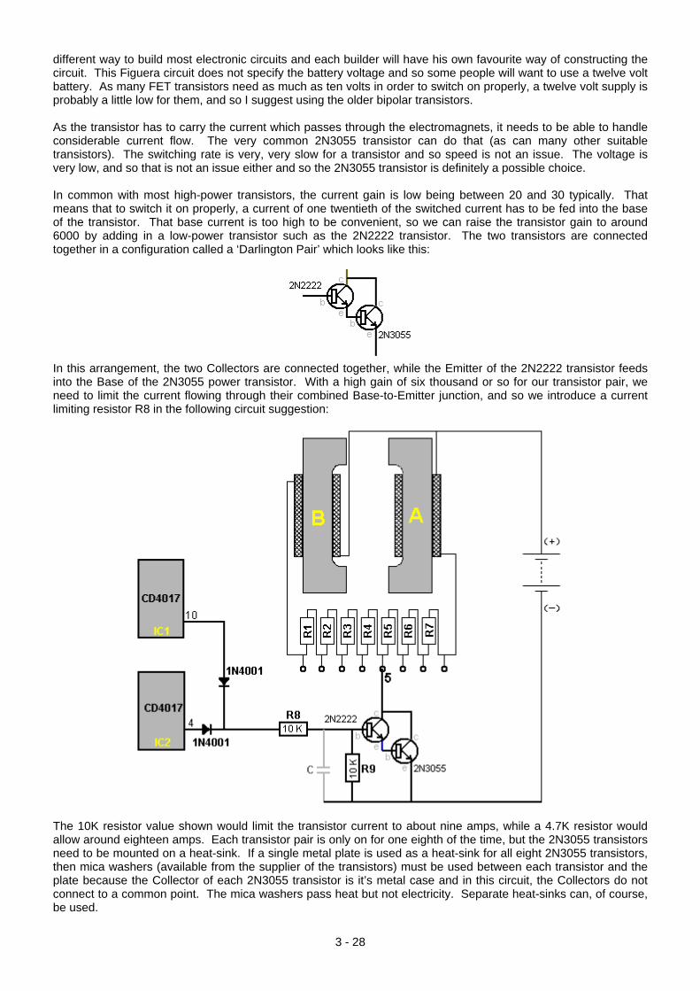
different way to build most electronic circuits and each builder will have his own favourite way of constructing the circuit. This Figuera circuit does not specify the battery voltage and so some people will want to use a twelve volt battery. As many FET transistors need as much as ten volts in order to switch on properly, a twelve volt supply is probably a little low for them, and so I suggest using the older bipolar transistors. As the transistor has to carry the current which passes through the electromagnets, it needs to be able to handle considerable current flow. The very common 2N3055 transistor can do that (as can many other suitable transistors). The switching rate is very, very slow for a transistor and so speed is not an issue. The voltage is very low, and so that is not an issue either and so the 2N3055 transistor is definitely a possible choice. In common with most high-power transistors, the current gain is low being between 20 and 30 typically. That means that to switch it on properly, a current of one twentieth of the switched current has to be fed into the base of the transistor. That base current is too high to be convenient, so we can raise the transistor gain to around 6000 by adding in a low-power transistor such as the 2N2222 transistor. The two transistors are connected together in a configuration called a ‘Darlington Pair’ which looks like this:
In this arrangement, the two Collectors are connected together, while the Emitter of the 2N2222 transistor feeds into the Base of the 2N3055 power transistor. With a high gain of six thousand or so for our transistor pair, we need to limit the current flowing through their combined Base-to-Emitter junction, and so we introduce a current limiting resistor R8 in the following circuit suggestion:
The 10K resistor value shown would limit the transistor current to about nine amps, while a 4.7K resistor would allow around eighteen amps. Each transistor pair is only on for one eighth of the time, but the 2N3055 transistors need to be mounted on a heat-sink. If a single metal plate is used as a heat-sink for all eight 2N3055 transistors, then mica washers (available from the supplier of the transistors) must be used between each transistor and the plate because the Collector of each 2N3055 transistor is it’s metal case and in this circuit, the Collectors do not connect to a common point. The mica washers pass heat but not electricity. Separate heat-sinks can, of course, be used.
3 - 28
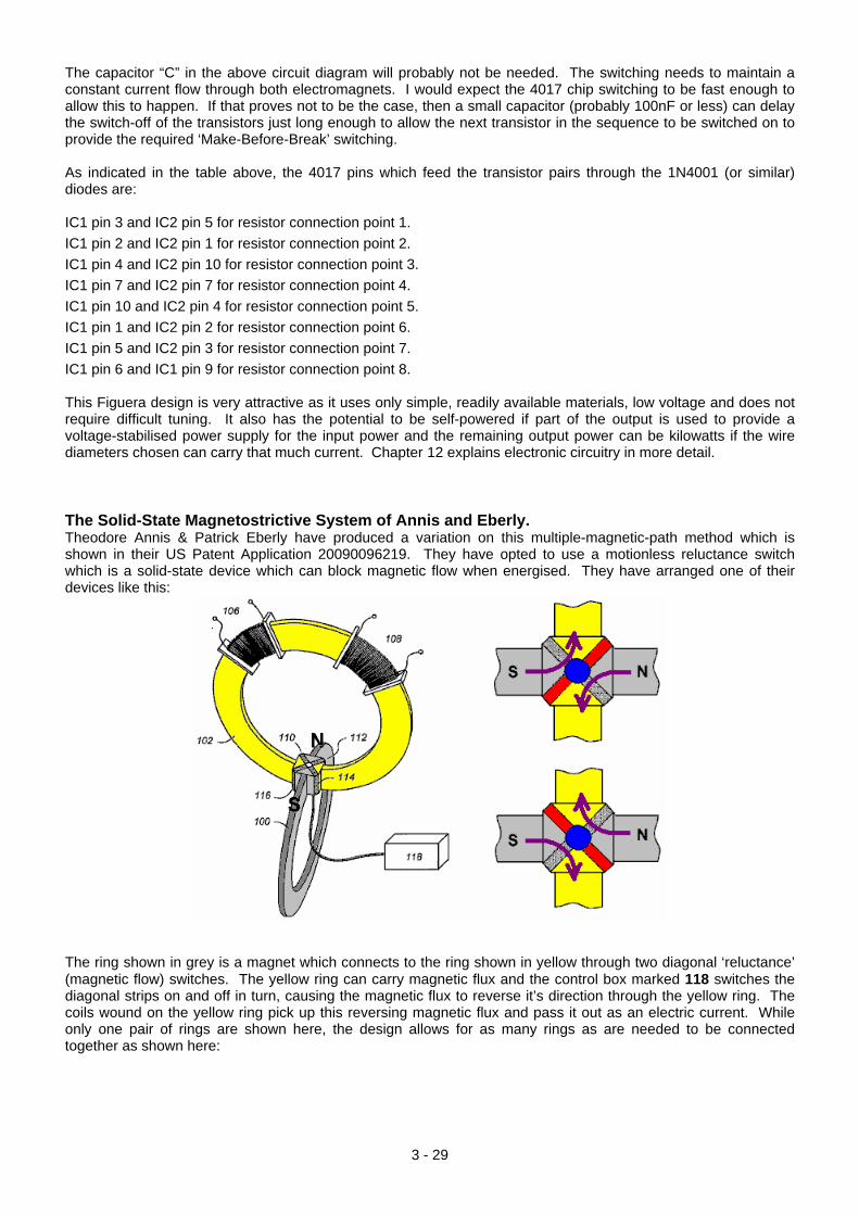
The capacitor “C” in the above circuit diagram will probably not be needed. The switching needs to maintain a constant current flow through both electromagnets. I would expect the 4017 chip switching to be fast enough to allow this to happen. If that proves not to be the case, then a small capacitor (probably 100nF or less) can delay the switch-off of the transistors just long enough to allow the next transistor in the sequence to be switched on to provide the required ‘Make-Before-Break’ switching. As indicated in the table above, the 4017 pins which feed the transistor pairs through the 1N4001 (or similar) diodes are: IC1 pin 3 and IC2 pin 5 for resistor connection point 1. IC1 pin 2 and IC2 pin 1 for resistor connection point 2. IC1 pin 4 and IC2 pin 10 for resistor connection point 3. IC1 pin 7 and IC2 pin 7 for resistor connection point 4. IC1 pin 10 and IC2 pin 4 for resistor connection point 5. IC1 pin 1 and IC2 pin 2 for resistor connection point 6. IC1 pin 5 and IC2 pin 3 for resistor connection point 7. IC1 pin 6 and IC1 pin 9 for resistor connection point 8. This Figuera design is very attractive as it uses only simple, readily available materials, low voltage and does not require difficult tuning. It also has the potential to be self-powered if part of the output is used to provide a voltage-stabilised power supply for the input power and the remaining output power can be kilowatts if the wire diameters chosen can carry that much current. Chapter 12 explains electronic circuitry in more detail. The Solid-State Magnetostrictive System of Annis and Eberly. Theodore Annis & Patrick Eberly have produced a variation on this multiple-magnetic-path method which is shown in their US Patent Application 20090096219. They have opted to use a motionless reluctance switch which is a solid-state device which can block magnetic flow when energised. They have arranged one of their devices like this:
The ring shown in grey is a magnet which connects to the ring shown in yellow through two diagonal ‘reluctance’ (magnetic flow) switches. The yellow ring can carry magnetic flux and the control box marked 118 switches the diagonal strips on and off in turn, causing the magnetic flux to reverse it’s direction through the yellow ring. The coils wound on the yellow ring pick up this reversing magnetic flux and pass it out as an electric current. While only one pair of rings are shown here, the design allows for as many rings as are needed to be connected together as shown here:
3 - 29
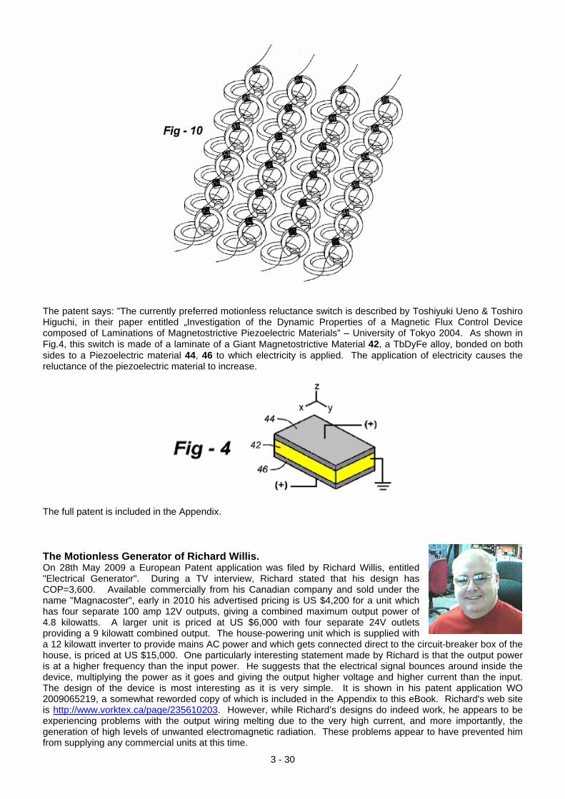
The patent says: ”The currently preferred motionless reluctance switch is described by Toshiyuki Ueno & Toshiro Higuchi, in their paper entitled „Investigation of the Dynamic Properties of a Magnetic Flux Control Device composed of Laminations of Magnetostrictive Piezoelectric Materials” – University of Tokyo 2004. As shown in Fig.4, this switch is made of a laminate of a Giant Magnetostrictive Material 42, a TbDyFe alloy, bonded on both sides to a Piezoelectric material 44, 46 to which electricity is applied. The application of electricity causes the reluctance of the piezoelectric material to increase.
The full patent is included in the Appendix. The Motionless Generator of Richard Willis. On 28th May 2009 a European Patent application was filed by Richard Willis, entitled "Electrical Generator". During a TV interview, Richard stated that his design has COP=3,600. Available commercially from his Canadian company and sold under the name "Magnacoster", early in 2010 his advertised pricing is US $4,200 for a unit which has four separate 100 amp 12V outputs, giving a combined maximum output power of 4.8 kilowatts. A larger unit is priced at US $6,000 with four separate 24V outlets providing a 9 kilowatt combined output. The house-powering unit which is supplied with a 12 kilowatt inverter to provide mains AC power and which gets connected direct to the circuit-breaker box of the house, is priced at US $15,000. One particularly interesting statement made by Richard is that the output power is at a higher frequency than the input power. He suggests that the electrical signal bounces around inside the device, multiplying the power as it goes and giving the output higher voltage and higher current than the input. The design of the device is most interesting as it is very simple. It is shown in his patent application WO 2009065219, a somewhat reworded copy of which is included in the Appendix to this eBook. Richard's web site is http://www.vorktex.ca/page/235610203. However, while Richard’s designs do indeed work, he appears to be experiencing problems with the output wiring melting due to the very high current, and more importantly, the generation of high levels of unwanted electromagnetic radiation. These problems appear to have prevented him from supplying any commercial units at this time.
3 - 30
The circuit is based on a pulsed coil and two magnets and it has a number of unusual features. The power supply is unusual:
Richard arranges it like this so that either DC or AC can be used as the input power and so he follows that arrangement with a diode bridge, followed by two more diodes as shown here:
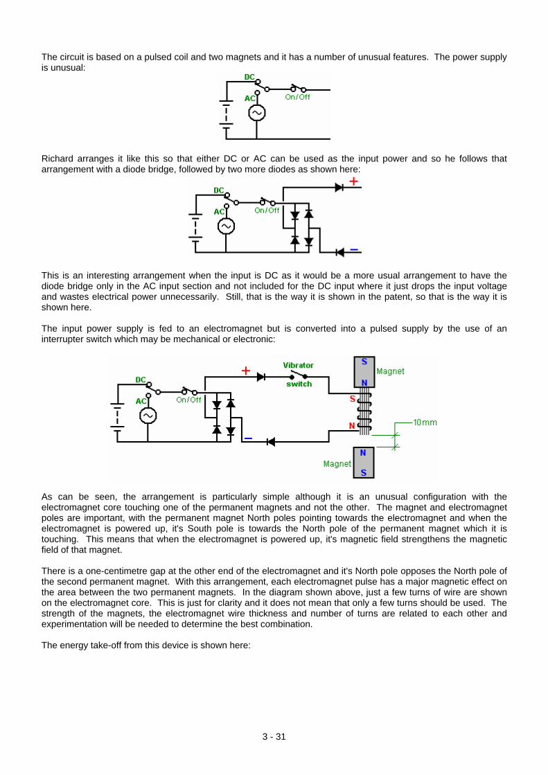
This is an interesting arrangement when the input is DC as it would be a more usual arrangement to have the diode bridge only in the AC input section and not included for the DC input where it just drops the input voltage and wastes electrical power unnecessarily. Still, that is the way it is shown in the patent, so that is the way it is shown here. The input power supply is fed to an electromagnet but is converted into a pulsed supply by the use of an interrupter switch which may be mechanical or electronic:
As can be seen, the arrangement is particularly simple although it is an unusual configuration with the electromagnet core touching one of the permanent magnets and not the other. The magnet and electromagnet poles are important, with the permanent magnet North poles pointing towards the electromagnet and when the electromagnet is powered up, it's South pole is towards the North pole of the permanent magnet which it is touching. This means that when the electromagnet is powered up, it's magnetic field strengthens the magnetic field of that magnet. There is a one-centimetre gap at the other end of the electromagnet and it's North pole opposes the North pole of the second permanent magnet. With this arrangement, each electromagnet pulse has a major magnetic effect on the area between the two permanent magnets. In the diagram shown above, just a few turns of wire are shown on the electromagnet core. This is just for clarity and it does not mean that only a few turns should be used. The strength of the magnets, the electromagnet wire thickness and number of turns are related to each other and experimentation will be needed to determine the best combination. The energy take-off from this device is shown here:
3 - 31
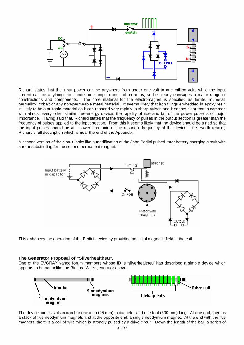
Richard states that the input power can be anywhere from under one volt to one million volts while the input current can be anything from under one amp to one million amps, so he clearly envisages a major range of constructions and components. The core material for the electromagnet is specified as ferrite, mumetal, permalloy, cobalt or any non-permeable metal material. It seems likely that iron filings embedded in epoxy resin is likely to be a suitable material as it can respond very rapidly to sharp pulses and it seems clear that in common with almost every other similar free-energy device, the rapidity of rise and fall of the power pulse is of major importance. Having said that, Richard states that the frequency of pulses in the output section is greater than the frequency of pulses applied to the input section. From this it seems likely that the device should be tuned so that the input pulses should be at a lower harmonic of the resonant frequency of the device. It is worth reading Richard's full description which is near the end of the Appendix. A second version of the circuit looks like a modification of the John Bedini pulsed rotor battery charging circuit with a rotor substituting for the second permanent magnet:
This enhances the operation of the Bedini device by providing an initial magnetic field in the coil. The Generator Proposal of “Silverhealtheu”. One of the EVGRAY yahoo forum members whose ID is ‘silverhealtheu’ has described a simple device which appears to be not unlike the Richard Willis generator above.
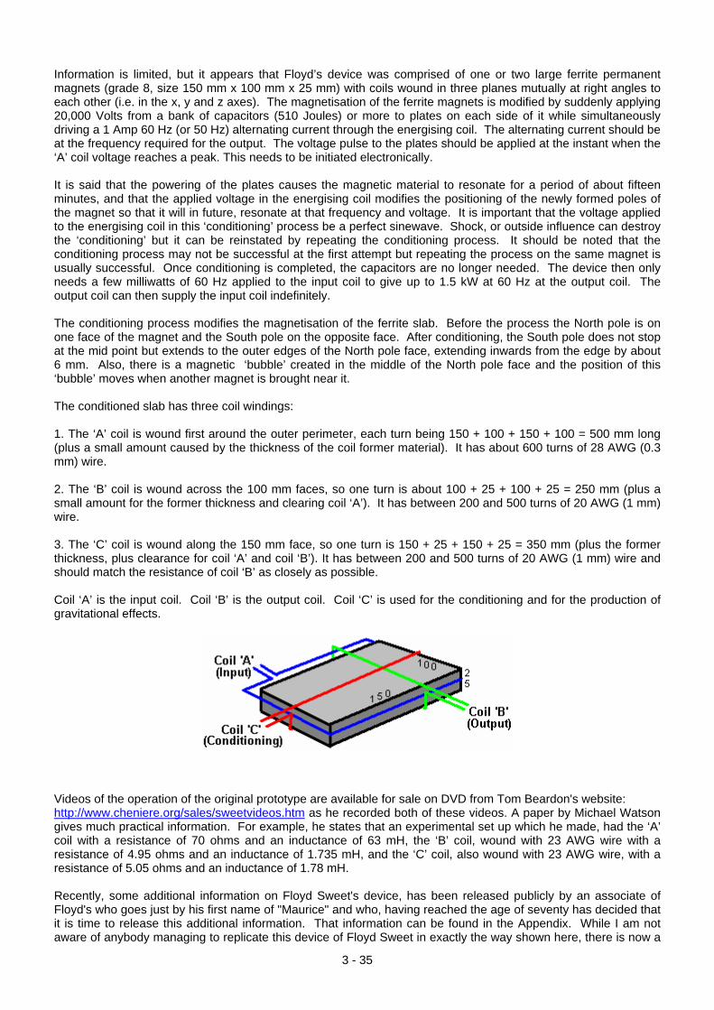
The device consists of an iron bar one inch (25 mm) in diameter and one foot (300 mm) long. At one end, there is a stack of five neodymium magnets and at the opposite end, a single neodymium magnet. At the end with the five magnets, there is a coil of wire which is strongly pulsed by a drive circuit. Down the length of the bar, a series of
3 - 32
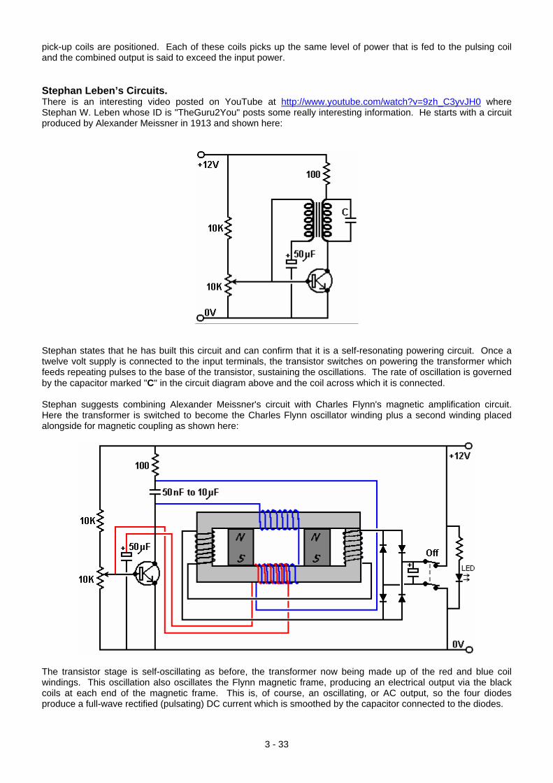
pick-up coils are positioned. Each of these coils picks up the same level of power that is fed to the pulsing coil and the combined output is said to exceed the input power. Stephan Leben’s Circuits. There is an interesting video posted on YouTube at http://www.youtube.com/watch?v=9zh_C3yvJH0 where Stephan W. Leben whose ID is "TheGuru2You" posts some really interesting information. He starts with a circuit produced by Alexander Meissner in 1913 and shown here:
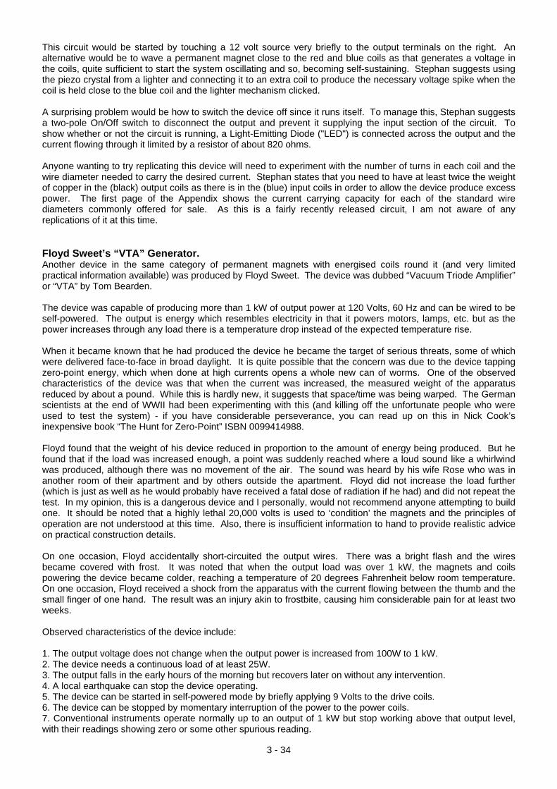
Stephan states that he has built this circuit and can confirm that it is a self-resonating powering circuit. Once a twelve volt supply is connected to the input terminals, the transistor switches on powering the transformer which feeds repeating pulses to the base of the transistor, sustaining the oscillations. The rate of oscillation is governed by the capacitor marked "C" in the circuit diagram above and the coil across which it is connected. Stephan suggests combining Alexander Meissner's circuit with Charles Flynn's magnetic amplification circuit. Here the transformer is switched to become the Charles Flynn oscillator winding plus a second winding placed alongside for magnetic coupling as shown here:
The transistor stage is self-oscillating as before, the transformer now being made up of the red and blue coil windings. This oscillation also oscillates the Flynn magnetic frame, producing an electrical output via the black coils at each end of the magnetic frame. This is, of course, an oscillating, or AC output, so the four diodes produce a full-wave rectified (pulsating) DC current which is smoothed by the capacitor connected to the diodes.
3 - 33
3 - 34
This circuit would be started by touching a 12 volt source very briefly to the output terminals on the right. An alternative would be to wave a permanent magnet close to the red and blue coils as that generates a voltage in the coils, quite sufficient to start the system oscillating and so, becoming self-sustaining. Stephan suggests using the piezo crystal from a lighter and connecting it to an extra coil to produce the necessary voltage spike when the coil is held close to the blue coil and the lighter mechanism clicked. A surprising problem would be how to switch the device off since it runs itself. To manage this, Stephan suggests a two-pole On/Off switch to disconnect the output and prevent it supplying the input section of the circuit. To show whether or not the circuit is running, a Light-Emitting Diode ("LED") is connected across the output and the current flowing through it limited by a resistor of about 820 ohms. Anyone wanting to try replicating this device will need to experiment with the number of turns in each coil and the wire diameter needed to carry the desired current. Stephan states that you need to have at least twice the weight of copper in the (black) output coils as there is in the (blue) input coils in order to allow the device produce excess power. The first page of the Appendix shows the current carrying capacity for each of the standard wire diameters commonly offered for sale. As this is a fairly recently released circuit, I am not aware of any replications of it at this time. Floyd Sweet’s “VTA” Generator. Another device in the same category of permanent magnets with energised coils round it (and very limited practical information available) was produced by Floyd Sweet. The device was dubbed “Vacuum Triode Amplifier” or “VTA” by Tom Bearden. The device was capable of producing more than 1 kW of output power at 120 Volts, 60 Hz and can be wired to be self-powered. The output is energy which resembles electricity in that it powers motors, lamps, etc. but as the power increases through any load there is a temperature drop instead of the expected temperature rise. When it became known that he had produced the device he became the target of serious threats, some of which were delivered face-to-face in broad daylight. It is quite possible that the concern was due to the device tapping zero-point energy, which when done at high currents opens a whole new can of worms. One of the observed characteristics of the device was that when the current was increased, the measured weight of the apparatus reduced by about a pound. While this is hardly new, it suggests that space/time was being warped. The German scientists at the end of WWII had been experimenting with this (and killing off the unfortunate people who were used to test the system) - if you have considerable perseverance, you can read up on this in Nick Cook’s inexpensive book “The Hunt for Zero-Point” ISBN 0099414988. Floyd found that the weight of his device reduced in proportion to the amount of energy being produced. But he found that if the load was increased enough, a point was suddenly reached where a loud sound like a whirlwind was produced, although there was no movement of the air. The sound was heard by his wife Rose who was in another room of their apartment and by others outside the apartment. Floyd did not increase the load further (which is just as well as he would probably have received a fatal dose of radiation if he had) and did not repeat the test. In my opinion, this is a dangerous device and I personally, would not recommend anyone attempting to build one. It should be noted that a highly lethal 20,000 volts is used to ‘condition’ the magnets and the principles of operation are not understood at this time. Also, there is insufficient information to hand to provide realistic advice on practical construction details. On one occasion, Floyd accidentally short-circuited the output wires. There was a bright flash and the wires became covered with frost. It was noted that when the output load was over 1 kW, the magnets and coils powering the device became colder, reaching a temperature of 20 degrees Fahrenheit below room temperature. On one occasion, Floyd received a shock from the apparatus with the current flowing between the thumb and the small finger of one hand. The result was an injury akin to frostbite, causing him considerable pain for at least two weeks. Observed characteristics of the device include: 1. The output voltage does not change when the output power is increased from 100W to 1 kW. 2. The device needs a continuous load of at least 25W. 3. The output falls in the early hours of the morning but recovers later on without any intervention. 4. A local earthquake can stop the device operating. 5. The device can be started in self-powered mode by briefly applying 9 Volts to the drive coils. 6. The device can be stopped by momentary interruption of the power to the power coils. 7. Conventional instruments operate normally up to an output of 1 kW but stop working above that output level, with their readings showing zero or some other spurious reading.
Information is limited, but it appears that Floyd’s device was comprised of one or two large ferrite permanent magnets (grade 8, size 150 mm x 100 mm x 25 mm) with coils wound in three planes mutually at right angles to each other (i.e. in the x, y and z axes). The magnetisation of the ferrite magnets is modified by suddenly applying 20,000 Volts from a bank of capacitors (510 Joules) or more to plates on each side of it while simultaneously driving a 1 Amp 60 Hz (or 50 Hz) alternating current through the energising coil. The alternating current should be at the frequency required for the output. The voltage pulse to the plates should be applied at the instant when the ‘A’ coil voltage reaches a peak. This needs to be initiated electronically. It is said that the powering of the plates causes the magnetic material to resonate for a period of about fifteen minutes, and that the applied voltage in the energising coil modifies the positioning of the newly formed poles of the magnet so that it will in future, resonate at that frequency and voltage. It is important that the voltage applied to the energising coil in this ‘conditioning’ process be a perfect sinewave. Shock, or outside influence can destroy the ‘conditioning’ but it can be reinstated by repeating the conditioning process. It should be noted that the conditioning process may not be successful at the first attempt but repeating the process on the same magnet is usually successful. Once conditioning is completed, the capacitors are no longer needed. The device then only needs a few milliwatts of 60 Hz applied to the input coil to give up to 1.5 kW at 60 Hz at the output coil. The output coil can then supply the input coil indefinitely. The conditioning process modifies the magnetisation of the ferrite slab. Before the process the North pole is on one face of the magnet and the South pole on the opposite face. After conditioning, the South pole does not stop at the mid point but extends to the outer edges of the North pole face, extending inwards from the edge by about 6 mm. Also, there is a magnetic ‘bubble’ created in the middle of the North pole face and the position of this ‘bubble’ moves when another magnet is brought near it. The conditioned slab has three coil windings: 1. The ‘A’ coil is wound first around the outer perimeter, each turn being 150 + 100 + 150 + 100 = 500 mm long (plus a small amount caused by the thickness of the coil former material). It has about 600 turns of 28 AWG (0.3 mm) wire. 2. The ‘B’ coil is wound across the 100 mm faces, so one turn is about 100 + 25 + 100 + 25 = 250 mm (plus a small amount for the former thickness and clearing coil ‘A’). It has between 200 and 500 turns of 20 AWG (1 mm) wire. 3. The ‘C’ coil is wound along the 150 mm face, so one turn is 150 + 25 + 150 + 25 = 350 mm (plus the former thickness, plus clearance for coil ‘A’ and coil ‘B’). It has between 200 and 500 turns of 20 AWG (1 mm) wire and should match the resistance of coil ‘B’ as closely as possible. Coil ‘A’ is the input coil. Coil ‘B’ is the output coil. Coil ‘C’ is used for the conditioning and for the production of gravitational effects.
Videos of the operation of the original prototype are available for sale on DVD from Tom Beardon's website: http://www.cheniere.org/sales/sweetvideos.htm as he recorded both of these videos. A paper by Michael Watson gives much practical information. For example, he states that an experimental set up which he made, had the ‘A’ coil with a resistance of 70 ohms and an inductance of 63 mH, the ‘B’ coil, wound with 23 AWG wire with a resistance of 4.95 ohms and an inductance of 1.735 mH, and the ‘C’ coil, also wound with 23 AWG wire, with a resistance of 5.05 ohms and an inductance of 1.78 mH. Recently, some additional information on Floyd Sweet's device, has been released publicly by an associate of Floyd's who goes just by his first name of "Maurice" and who, having reached the age of seventy has decided that it is time to release this additional information. That information can be found in the Appendix. While I am not aware of anybody managing to replicate this device of Floyd Sweet in exactly the way shown here, there is now a
3 - 35
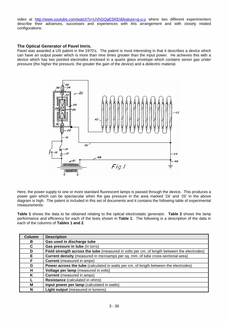
video at http://www.youtube.com/watch?v=UVhGQaESKEI&feature=g-u-u where two different experimenters describe their advances, successes and experiences with this arrangement and with closely related configurations. The Optical Generator of Pavel Imris. Pavel was awarded a US patent in the 1970’s. The patent is most interesting in that it describes a device which can have an output power which is more than nine times greater than the input power. He achieves this with a device which has two pointed electrodes enclosed in a quartz glass envelope which contains xenon gas under pressure (the higher the pressure, the greater the gain of the device) and a dielectric material.
Here, the power supply to one or more standard fluorescent lamps is passed through the device. This produces a power gain which can be spectacular when the gas pressure in the area marked ‘24’ and ‘25’ in the above diagram is high. The patent is included in this set of documents and it contains the following table of experimental measurements: Table 1 shows the data to be obtained relating to the optical electrostatic generator. Table 2 shows the lamp performance and efficiency for each of the tests shown in Table 1. The following is a description of the data in each of the columns of Tables 1 and 2.
Column Description B Gas used in discharge tube C Gas pressure in tube (in torrs) D Field strength across the tube (measured in volts per cm. of length between the electrodes) E Current density (measured in microamps per sq. mm. of tube cross-sectional area) F Current (measured in amps) G Power across the tube (calculated in watts per cm. of length between the electrodes) H Voltage per lamp (measured in volts) K Current (measured in amps) L Resistance (calculated in ohms) M Input power per lamp (calculated in watts) N Light output (measured in lumens)
3 - 36
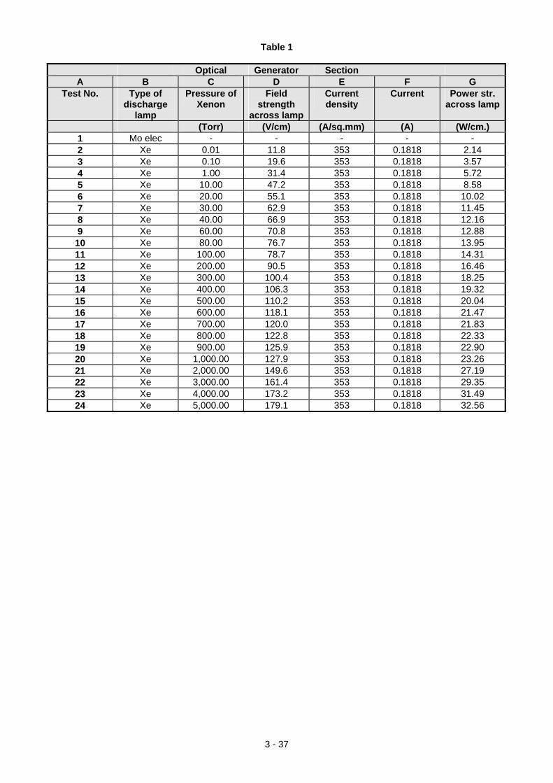
3 - 37
Table 1
Optical Generator Section A B C D E F G
Test No. Type of discharge
lamp
Pressure of Xenon
Field strength
across lamp
Current density
Current Power str. across lamp
(Torr) (V/cm) (A/sq.mm) (A) (W/cm.) 1 Mo elec - - - - - 2 Xe 0.01 11.8 353 0.1818 2.14 3 Xe 0.10 19.6 353 0.1818 3.57 4 Xe 1.00 31.4 353 0.1818 5.72 5 Xe 10.00 47.2 353 0.1818 8.58 6 Xe 20.00 55.1 353 0.1818 10.02 7 Xe 30.00 62.9 353 0.1818 11.45 8 Xe 40.00 66.9 353 0.1818 12.16 9 Xe 60.00 70.8 353 0.1818 12.88
10 Xe 80.00 76.7 353 0.1818 13.95 11 Xe 100.00 78.7 353 0.1818 14.31 12 Xe 200.00 90.5 353 0.1818 16.46 13 Xe 300.00 100.4 353 0.1818 18.25 14 Xe 400.00 106.3 353 0.1818 19.32 15 Xe 500.00 110.2 353 0.1818 20.04 16 Xe 600.00 118.1 353 0.1818 21.47 17 Xe 700.00 120.0 353 0.1818 21.83 18 Xe 800.00 122.8 353 0.1818 22.33 19 Xe 900.00 125.9 353 0.1818 22.90 20 Xe 1,000.00 127.9 353 0.1818 23.26 21 Xe 2,000.00 149.6 353 0.1818 27.19 22 Xe 3,000.00 161.4 353 0.1818 29.35 23 Xe 4,000.00 173.2 353 0.1818 31.49 24 Xe 5,000.00 179.1 353 0.1818 32.56
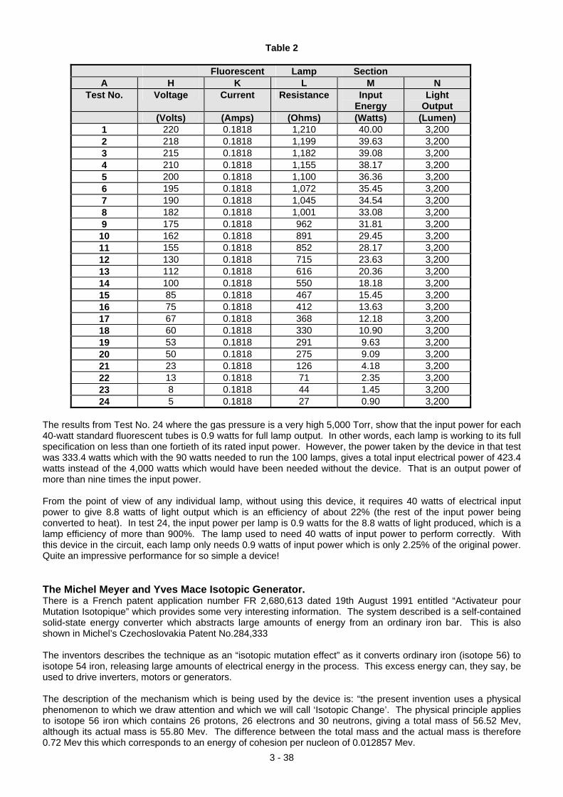
3 - 38
Table 2
Fluorescent Lamp Section A H K L M N
Test No. Voltage Current Resistance Input Energy
Light Output
(Volts) (Amps) (Ohms) (Watts) (Lumen) 1 220 0.1818 1,210 40.00 3,200 2 218 0.1818 1,199 39.63 3,200 3 215 0.1818 1,182 39.08 3,200 4 210 0.1818 1,155 38.17 3,200 5 200 0.1818 1,100 36.36 3,200 6 195 0.1818 1,072 35.45 3,200 7 190 0.1818 1,045 34.54 3,200 8 182 0.1818 1,001 33.08 3,200 9 175 0.1818 962 31.81 3,200
10 162 0.1818 891 29.45 3,200 11 155 0.1818 852 28.17 3,200 12 130 0.1818 715 23.63 3,200 13 112 0.1818 616 20.36 3,200 14 100 0.1818 550 18.18 3,200 15 85 0.1818 467 15.45 3,200 16 75 0.1818 412 13.63 3,200 17 67 0.1818 368 12.18 3,200 18 60 0.1818 330 10.90 3,200 19 53 0.1818 291 9.63 3,200 20 50 0.1818 275 9.09 3,200 21 23 0.1818 126 4.18 3,200 22 13 0.1818 71 2.35 3,200 23 8 0.1818 44 1.45 3,200 24 5 0.1818 27 0.90 3,200
The results from Test No. 24 where the gas pressure is a very high 5,000 Torr, show that the input power for each 40-watt standard fluorescent tubes is 0.9 watts for full lamp output. In other words, each lamp is working to its full specification on less than one fortieth of its rated input power. However, the power taken by the device in that test was 333.4 watts which with the 90 watts needed to run the 100 lamps, gives a total input electrical power of 423.4 watts instead of the 4,000 watts which would have been needed without the device. That is an output power of more than nine times the input power. From the point of view of any individual lamp, without using this device, it requires 40 watts of electrical input power to give 8.8 watts of light output which is an efficiency of about 22% (the rest of the input power being converted to heat). In test 24, the input power per lamp is 0.9 watts for the 8.8 watts of light produced, which is a lamp efficiency of more than 900%. The lamp used to need 40 watts of input power to perform correctly. With this device in the circuit, each lamp only needs 0.9 watts of input power which is only 2.25% of the original power. Quite an impressive performance for so simple a device! The Michel Meyer and Yves Mace Isotopic Generator. There is a French patent application number FR 2,680,613 dated 19th August 1991 entitled “Activateur pour Mutation Isotopique” which provides some very interesting information. The system described is a self-contained solid-state energy converter which abstracts large amounts of energy from an ordinary iron bar. This is also shown in Michel’s Czechoslovakia Patent No.284,333 The inventors describes the technique as an “isotopic mutation effect” as it converts ordinary iron (isotope 56) to isotope 54 iron, releasing large amounts of electrical energy in the process. This excess energy can, they say, be used to drive inverters, motors or generators. The description of the mechanism which is being used by the device is: “the present invention uses a physical phenomenon to which we draw attention and which we will call ‘Isotopic Change’. The physical principle applies to isotope 56 iron which contains 26 protons, 26 electrons and 30 neutrons, giving a total mass of 56.52 Mev, although its actual mass is 55.80 Mev. The difference between the total mass and the actual mass is therefore 0.72 Mev this which corresponds to an energy of cohesion per nucleon of 0.012857 Mev.
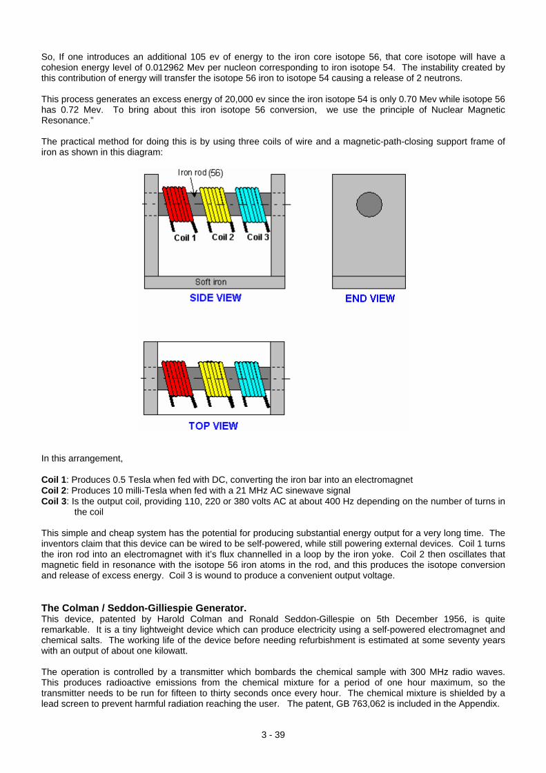
So, If one introduces an additional 105 ev of energy to the iron core isotope 56, that core isotope will have a cohesion energy level of 0.012962 Mev per nucleon corresponding to iron isotope 54. The instability created by this contribution of energy will transfer the isotope 56 iron to isotope 54 causing a release of 2 neutrons. This process generates an excess energy of 20,000 ev since the iron isotope 54 is only 0.70 Mev while isotope 56 has 0.72 Mev. To bring about this iron isotope 56 conversion, we use the principle of Nuclear Magnetic Resonance.” The practical method for doing this is by using three coils of wire and a magnetic-path-closing support frame of iron as shown in this diagram:
In this arrangement, Coil 1: Produces 0.5 Tesla when fed with DC, converting the iron bar into an electromagnet Coil 2: Produces 10 milli-Tesla when fed with a 21 MHz AC sinewave signal Coil 3: Is the output coil, providing 110, 220 or 380 volts AC at about 400 Hz depending on the number of turns in
the coil This simple and cheap system has the potential for producing substantial energy output for a very long time. The inventors claim that this device can be wired to be self-powered, while still powering external devices. Coil 1 turns the iron rod into an electromagnet with it’s flux channelled in a loop by the iron yoke. Coil 2 then oscillates that magnetic field in resonance with the isotope 56 iron atoms in the rod, and this produces the isotope conversion and release of excess energy. Coil 3 is wound to produce a convenient output voltage. The Colman / Seddon-Gilliespie Generator. This device, patented by Harold Colman and Ronald Seddon-Gillespie on 5th December 1956, is quite remarkable. It is a tiny lightweight device which can produce electricity using a self-powered electromagnet and chemical salts. The working life of the device before needing refurbishment is estimated at some seventy years with an output of about one kilowatt. The operation is controlled by a transmitter which bombards the chemical sample with 300 MHz radio waves. This produces radioactive emissions from the chemical mixture for a period of one hour maximum, so the transmitter needs to be run for fifteen to thirty seconds once every hour. The chemical mixture is shielded by a lead screen to prevent harmful radiation reaching the user. The patent, GB 763,062 is included in the Appendix.
3 - 39
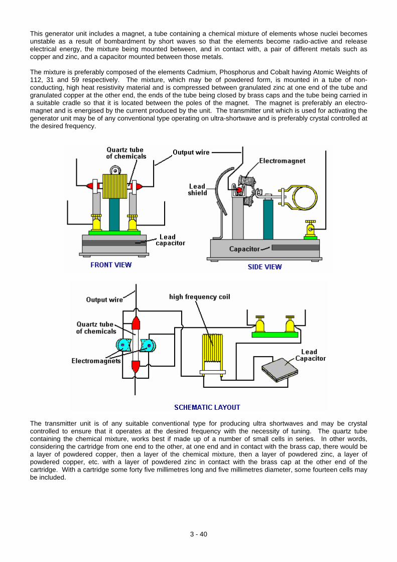
This generator unit includes a magnet, a tube containing a chemical mixture of elements whose nuclei becomes unstable as a result of bombardment by short waves so that the elements become radio-active and release electrical energy, the mixture being mounted between, and in contact with, a pair of different metals such as copper and zinc, and a capacitor mounted between those metals. The mixture is preferably composed of the elements Cadmium, Phosphorus and Cobalt having Atomic Weights of 112, 31 and 59 respectively. The mixture, which may be of powdered form, is mounted in a tube of non-conducting, high heat resistivity material and is compressed between granulated zinc at one end of the tube and granulated copper at the other end, the ends of the tube being closed by brass caps and the tube being carried in a suitable cradle so that it is located between the poles of the magnet. The magnet is preferably an electro-magnet and is energised by the current produced by the unit. The transmitter unit which is used for activating the generator unit may be of any conventional type operating on ultra-shortwave and is preferably crystal controlled at the desired frequency.
The transmitter unit is of any suitable conventional type for producing ultra shortwaves and may be crystal controlled to ensure that it operates at the desired frequency with the necessity of tuning. The quartz tube containing the chemical mixture, works best if made up of a number of small cells in series. In other words, considering the cartridge from one end to the other, at one end and in contact with the brass cap, there would be a layer of powdered copper, then a layer of the chemical mixture, then a layer of powdered zinc, a layer of powdered copper, etc. with a layer of powdered zinc in contact with the brass cap at the other end of the cartridge. With a cartridge some forty five millimetres long and five millimetres diameter, some fourteen cells may be included.
3 - 40
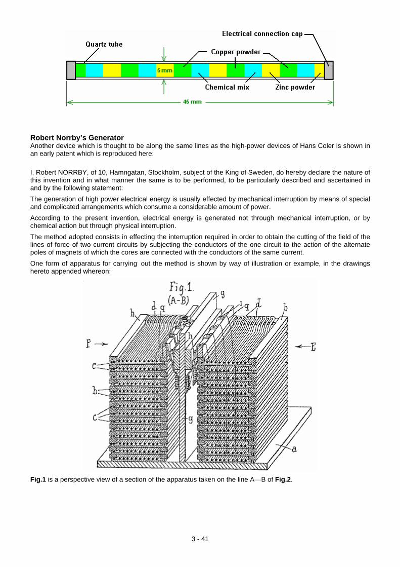
Robert Norrby’s Generator Another device which is thought to be along the same lines as the high-power devices of Hans Coler is shown in an early patent which is reproduced here: I, Robert NORRBY, of 10, Hamngatan, Stockholm, subject of the King of Sweden, do hereby declare the nature of this invention and in what manner the same is to be performed, to be particularly described and ascertained in and by the following statement: The generation of high power electrical energy is usually effected by mechanical interruption by means of special and complicated arrangements which consume a considerable amount of power. According to the present invention, electrical energy is generated not through mechanical interruption, or by chemical action but through physical interruption. The method adopted consists in effecting the interruption required in order to obtain the cutting of the field of the lines of force of two current circuits by subjecting the conductors of the one circuit to the action of the alternate poles of magnets of which the cores are connected with the conductors of the same current. One form of apparatus for carrying. out the method is shown by way of illustration or example, in the drawings hereto appended whereon:
Fig.1 is a perspective view of a section of the apparatus taken on the line A—B of Fig.2.
3 - 41
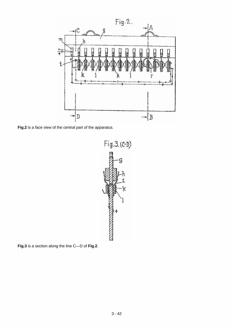
Fig.2 is a face view of the central part of the apparatus.
Fig.3 is a section along the line C—D of Fig.2.
3 - 42
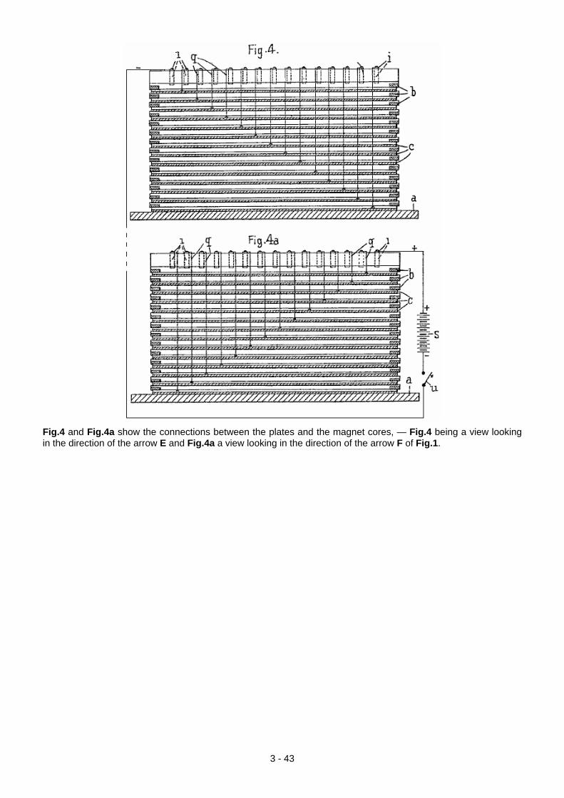
Fig.4 and Fig.4a show the connections between the plates and the magnet cores, — Fig.4 being a view looking in the direction of the arrow E and Fig.4a a view looking in the direction of the arrow F of Fig.1.
3 - 43
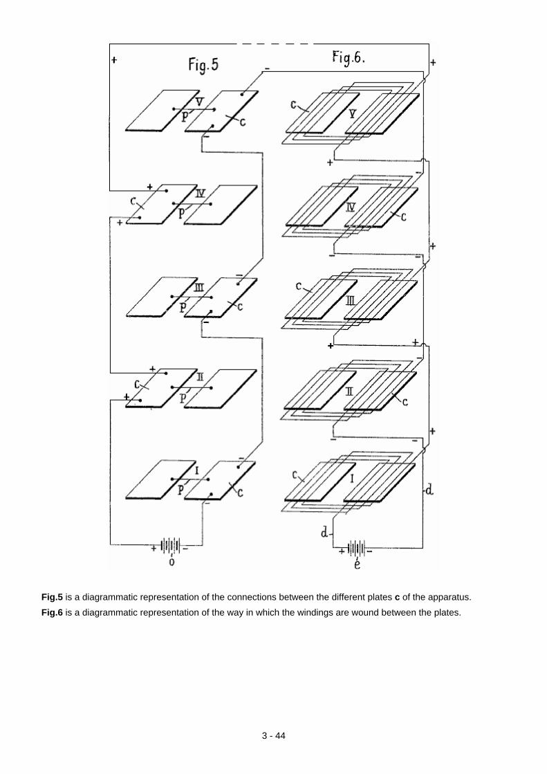
Fig.5 is a diagrammatic representation of the connections between the different plates c of the apparatus.
Fig.6 is a diagrammatic representation of the way in which the windings are wound between the plates.
3 - 44
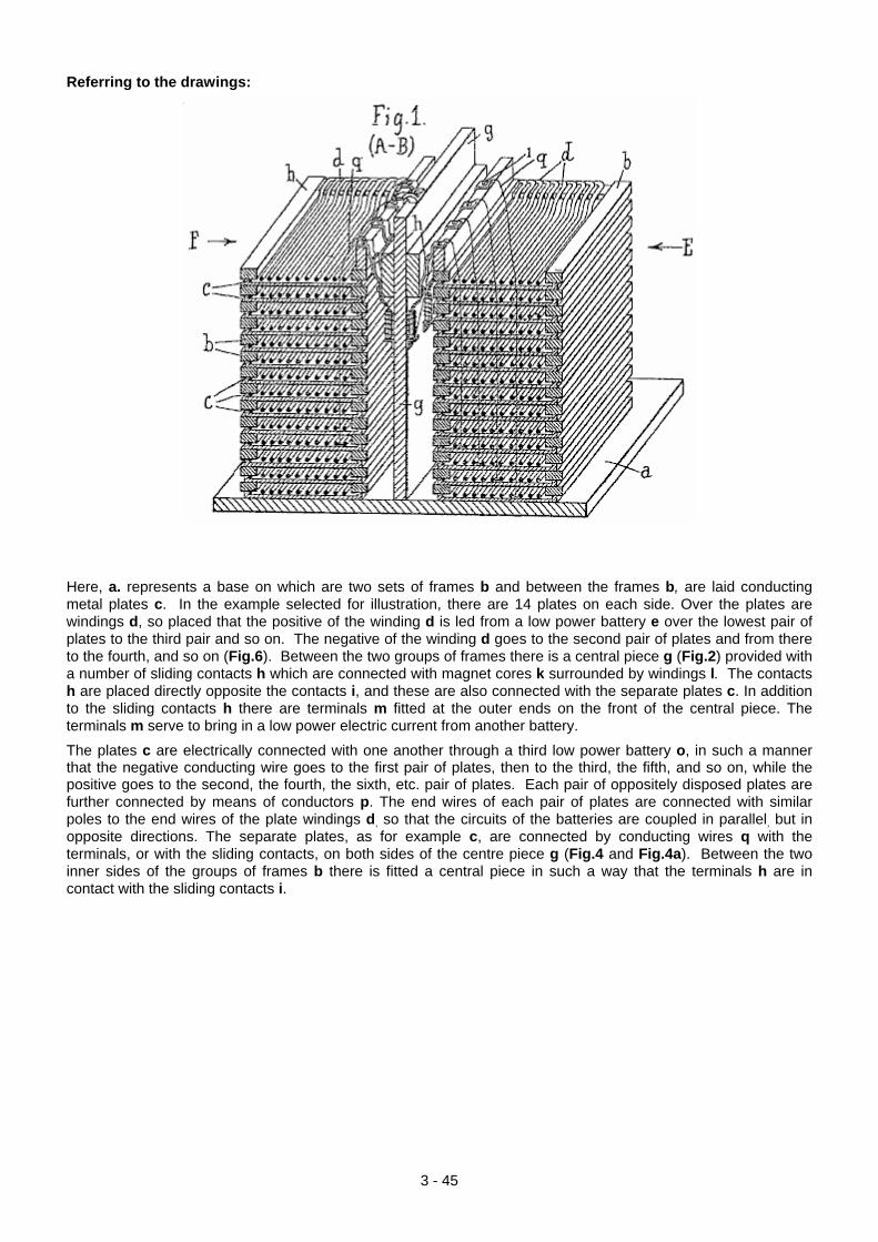
Referring to the drawings:
Here, a. represents a base on which are two sets of frames b and between the frames b, are laid conducting metal plates c. In the example selected for illustration, there are 14 plates on each side. Over the plates are windings d, so placed that the positive of the winding d is led from a low power battery e over the lowest pair of plates to the third pair and so on. The negative of the winding d goes to the second pair of plates and from there to the fourth, and so on (Fig.6). Between the two groups of frames there is a central piece g (Fig.2) provided with a number of sliding contacts h which are connected with magnet cores k surrounded by windings l. The contacts h are placed directly opposite the contacts i, and these are also connected with the separate plates c. In addition to the sliding contacts h there are terminals m fitted at the outer ends on the front of the central piece. The terminals m serve to bring in a low power electric current from another battery.
The plates c are electrically connected with one another through a third low power battery o, in such a manner that the negative conducting wire goes to the first pair of plates, then to the third, the fifth, and so on, while the positive goes to the second, the fourth, the sixth, etc. pair of plates. Each pair of oppositely disposed plates are further connected by means of conductors p. The end wires of each pair of plates are connected with similar poles to the end wires of the plate windings d, so that the circuits of the batteries are coupled in parallel, but in opposite directions. The separate plates, as for example c, are connected by conducting wires q with the terminals, or with the sliding contacts, on both sides of the centre piece g (Fig.4 and Fig.4a). Between the two inner sides of the groups of frames b there is fitted a central piece in such a way that the terminals h are in contact with the sliding contacts i.
3 - 45
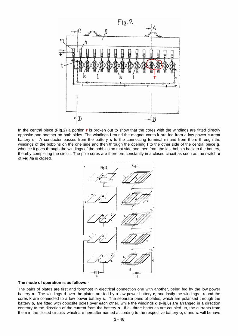
In the central piece (Fig.2) a portion r is broken out to show that the cores with the windings are fitted directly opposite one another on both sides. The windings I round the magnet cores k are fed from a low power current battery s. A conductor passes from the battery s to the connecting terminal m and from there through the windings of the bobbins on the one side and then through the opening t to the other side of the central piece g, whence it goes through the windings of the bobbins on that side and then from the last bobbin back to the battery, thereby completing the circuit. The pole cores are therefore constantly in a closed circuit as soon as the switch u of Fig.4a is closed.
The mode of operation is as follows:- The pairs of plates are first and foremost in electrical connection one with another, being fed by the low power battery o. The windings d over the plates are fed by a low power battery e, and lastly the windings l round the cores k are connected to a low power battery s. The separate pairs of plates, which are polarised through the battery o, are fitted with opposite poles over each other, while the windings d (Fig.6) are arranged in a direction contrary to the direction of the current from the battery o. If all three batteries are coupled up, the currents from them in the closed circuits, which are hereafter named according to the respective battery o, c and s, will behave
3 - 46
in the following way:
The currents o and e, which flow in contrary directions as already mentioned, bring about a constant state of tension between the field of the lines of force of the plate current and of the current in the windings. The constant tension is interrupted with very high frequency through the action of the magnet poles as soon as the third circuit is closed and the energy latent in the plates (rising up from below) is released through the high frequency interruptions. An increase of the final energy can be obtained be enlarging the size of the plates and/or by increasing their number. The current consumers are connected to the current generator in such a way that the line conductor is connected to the end terminals of the current circuits o and e which are brought together for the purpose. Having now particularly described and ascertained the nature of my invention, and in what manner the same is to be performed, I declare that what I claim is:— 1. A. method of generating electric energy without mechanical interruption, characterised in that the interruption required to cut the field of the lines of force of both current circuits is effected by alternately exposing the conductors of the one circuit to the action of the poles of magnets whose cores are in connection with the conductors of the same circuit. 2. Apparatus for carrying; out the method claimed in Claim 1, having the characteristic feature that a set of plates, arranged with their poles opposite to one another and in electrical connection through one with another with a low power current battery, lie between winding's which are supplied, from another low power battery, with current flowing in a direction opposite to the direction of the current passing through the plates: while at the same time, the plates are also in connection with the cores of magnets of which the windings are connected with a third low power current. in such a manner that when all the three circuits are closed the tension of the first circuit is physically interrupted with high frequency. Dated this 29th day of May, 1920.
The Devices of Don Smith. One free-energy developer who had most impressive claims for his devices is the late Don Smith who produced many spectacular devices, generally with major power output. Don says that his understanding comes from the work of Nikola Tesla as recorded in Thomas C. Martin's book "The Inventions, Researches, and Writings of Nikola Tesla" ISBN 0-7873-0582-0 available from http://www.healthresearchbooks.com and various other book companies. This book can be downloaded from http://www.free-energy-info.tuks.nl/ as a pdf file, but a paper copy is much better quality and easier to work from. Many experimenters have spent considerable time and effort in attempts to replicate the work which Don reports and while COP>1 has definitely been achieved, high power has not yet been reached. If you want more detail then it can be found here: http://www.free-energy-info.tuks.nl/DonSmith.pdf as a free download.
3 - 47
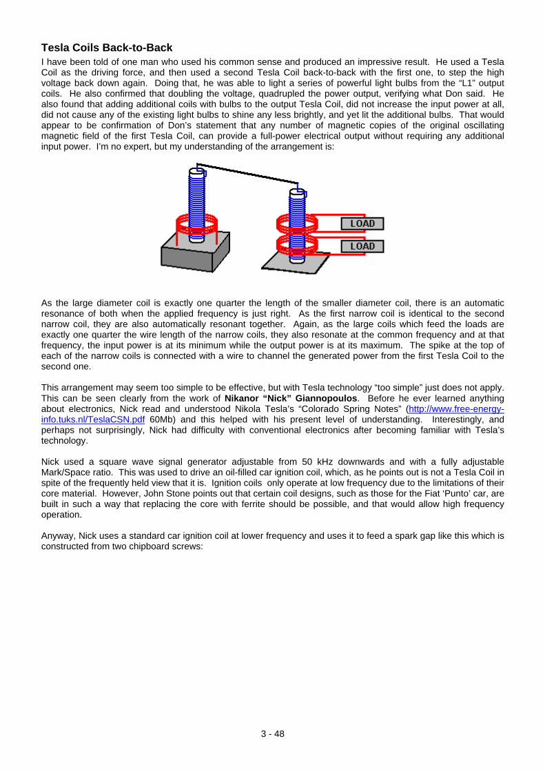
Tesla Coils Back-to-Back I have been told of one man who used his common sense and produced an impressive result. He used a Tesla Coil as the driving force, and then used a second Tesla Coil back-to-back with the first one, to step the high voltage back down again. Doing that, he was able to light a series of powerful light bulbs from the “L1” output coils. He also confirmed that doubling the voltage, quadrupled the power output, verifying what Don said. He also found that adding additional coils with bulbs to the output Tesla Coil, did not increase the input power at all, did not cause any of the existing light bulbs to shine any less brightly, and yet lit the additional bulbs. That would appear to be confirmation of Don’s statement that any number of magnetic copies of the original oscillating magnetic field of the first Tesla Coil, can provide a full-power electrical output without requiring any additional input power. I’m no expert, but my understanding of the arrangement is:
As the large diameter coil is exactly one quarter the length of the smaller diameter coil, there is an automatic resonance of both when the applied frequency is just right. As the first narrow coil is identical to the second narrow coil, they are also automatically resonant together. Again, as the large coils which feed the loads are exactly one quarter the wire length of the narrow coils, they also resonate at the common frequency and at that frequency, the input power is at its minimum while the output power is at its maximum. The spike at the top of each of the narrow coils is connected with a wire to channel the generated power from the first Tesla Coil to the second one. This arrangement may seem too simple to be effective, but with Tesla technology “too simple” just does not apply. This can be seen clearly from the work of Nikanor “Nick” Giannopoulos. Before he ever learned anything about electronics, Nick read and understood Nikola Tesla’s “Colorado Spring Notes” (http://www.free-energy-info.tuks.nl/TeslaCSN.pdf 60Mb) and this helped with his present level of understanding. Interestingly, and perhaps not surprisingly, Nick had difficulty with conventional electronics after becoming familiar with Tesla’s technology. Nick used a square wave signal generator adjustable from 50 kHz downwards and with a fully adjustable Mark/Space ratio. This was used to drive an oil-filled car ignition coil, which, as he points out is not a Tesla Coil in spite of the frequently held view that it is. Ignition coils only operate at low frequency due to the limitations of their core material. However, John Stone points out that certain coil designs, such as those for the Fiat ‘Punto’ car, are built in such a way that replacing the core with ferrite should be possible, and that would allow high frequency operation. Anyway, Nick uses a standard car ignition coil at lower frequency and uses it to feed a spark gap like this which is constructed from two chipboard screws:
3 - 48
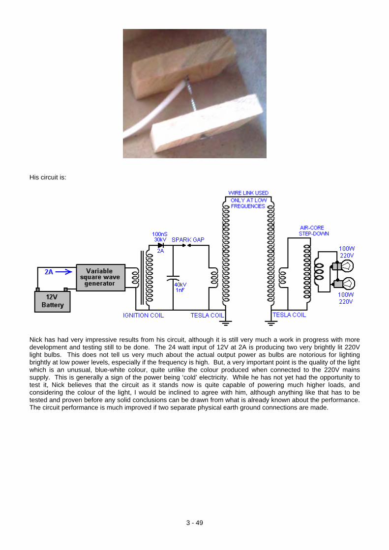
His circuit is:
Nick has had very impressive results from his circuit, although it is still very much a work in progress with more development and testing still to be done. The 24 watt input of 12V at 2A is producing two very brightly lit 220V light bulbs. This does not tell us very much about the actual output power as bulbs are notorious for lighting brightly at low power levels, especially if the frequency is high. But, a very important point is the quality of the light which is an unusual, blue-white colour, quite unlike the colour produced when connected to the 220V mains supply. This is generally a sign of the power being ‘cold’ electricity. While he has not yet had the opportunity to test it, Nick believes that the circuit as it stands now is quite capable of powering much higher loads, and considering the colour of the light, I would be inclined to agree with him, although anything like that has to be tested and proven before any solid conclusions can be drawn from what is already known about the performance. The circuit performance is much improved if two separate physical earth ground connections are made.
3 - 49
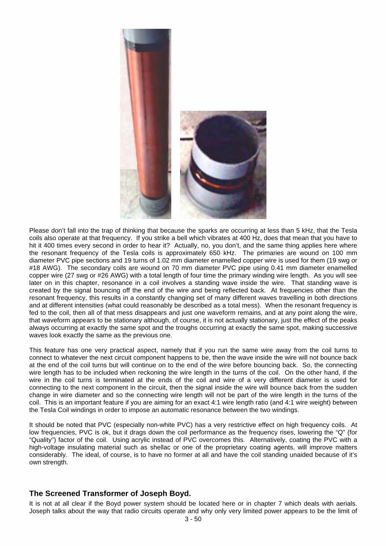
Please don’t fall into the trap of thinking that because the sparks are occurring at less than 5 kHz, that the Tesla coils also operate at that frequency. If you strike a bell which vibrates at 400 Hz, does that mean that you have to hit it 400 times every second in order to hear it? Actually, no, you don’t, and the same thing applies here where the resonant frequency of the Tesla coils is approximately 650 kHz. The primaries are wound on 100 mm diameter PVC pipe sections and 19 turns of 1.02 mm diameter enamelled copper wire is used for them (19 swg or #18 AWG). The secondary coils are wound on 70 mm diameter PVC pipe using 0.41 mm diameter enamelled copper wire (27 swg or #26 AWG) with a total length of four time the primary winding wire length. As you will see later on in this chapter, resonance in a coil involves a standing wave inside the wire. That standing wave is created by the signal bouncing off the end of the wire and being reflected back. At frequencies other than the resonant frequency, this results in a constantly changing set of many different waves travelling in both directions and at different intensities (what could reasonably be described as a total mess). When the resonant frequency is fed to the coil, then all of that mess disappears and just one waveform remains, and at any point along the wire, that waveform appears to be stationary although, of course, it is not actually stationary, just the effect of the peaks always occurring at exactly the same spot and the troughs occurring at exactly the same spot, making successive waves look exactly the same as the previous one. This feature has one very practical aspect, namely that if you run the same wire away from the coil turns to connect to whatever the next circuit component happens to be, then the wave inside the wire will not bounce back at the end of the coil turns but will continue on to the end of the wire before bouncing back. So, the connecting wire length has to be included when reckoning the wire length in the turns of the coil. On the other hand, if the wire in the coil turns is terminated at the ends of the coil and wire of a very different diameter is used for connecting to the next component in the circuit, then the signal inside the wire will bounce back from the sudden change in wire diameter and so the connecting wire length will not be part of the wire length in the turns of the coil. This is an important feature if you are aiming for an exact 4:1 wire length ratio (and 4:1 wire weight) between the Tesla Coil windings in order to impose an automatic resonance between the two windings. It should be noted that PVC (especially non-white PVC) has a very restrictive effect on high frequency coils. At low frequencies, PVC is ok, but it drags down the coil performance as the frequency rises, lowering the “Q” (for “Quality”) factor of the coil. Using acrylic instead of PVC overcomes this. Alternatively, coating the PVC with a high-voltage insulating material such as shellac or one of the proprietary coating agents, will improve matters considerably. The ideal, of course, is to have no former at all and have the coil standing unaided because of it’s own strength.
The Screened Transformer of Joseph Boyd.
3 - 50
It is not at all clear if the Boyd power system should be located here or in chapter 7 which deals with aerials. Joseph talks about the way that radio circuits operate and why only very limited power appears to be the limit of
3 - 51
radio receivers. He explains a method of extracting serious levels of power from a transmitting coil and a receiving coil, but the higher power levels require an input oscillator, and so, while an aerial and earth can be used for lower power levels, input power is needed for optimum performance. Here is part of Joseph’s patent application:
US Patent Application 2008/0129397 5th June 2008 Joseph Boyd
ELECTROMAGNETIC ELECTRIC GENERATOR Abstract: An electrical generator that uses a high frequency oscillator in a tuned circuit, set to resonate with the transmitter coil of a full-length high frequency transformer unit, to generate electromagnetic energy, to transform this energy to electrical energy and to collect this energy. 1. Field of the Invention The present invention is an electrical generator that uses a high frequency oscillator in a tuned circuit, set to resonate with the transmitter coil of a full-length high frequency transformer unit, to generate electromagnetic energy, to transform this energy to electrical energy and to collect this energy. 2. Description of the Related Art If an oscillator circuit is properly connected to a tuned antenna so that it resonates, a current will flow between the aerial and the ground, and this produces the high frequency electromagnetic air waves and ground waves of our radios and other electronic equipment. An oscillator of the same type used in electromagnetic wave transmission equipment is used to generate the electromagnetic energy used in this patent. These electromagnetic transmitters are well developed and are used world wide, and broadcast at frequencies that extend from the longest radio waves to the very short ones. Certain radios send their signals great distances, some even travelling around the world. Although these high frequency electromagnetic energy waves are all around us, this energy has long been considered impossible to collect on a large scale due to the induction characteristics of the electromagnetic wave as it passes a metallic object. As the wave goes by a wire tuned to resonate at the frequency of the wave, it induces an electrical charge in the wire, but to use this charge, we need another wire to close the circuit and let the charge flow. If we use another wire alongside the first wire and connected to it, the wave induces a charge in it exactly like in the first wire and no current will circulate in the two wires. This problem of collecting the energy of the wave was solved by the invention of the half-length electromagnetic transformer, but the half-length electromagnetic transformer applies only to the means of collecting the atmospheric energy. The invention of the full-length electromagnetic transformer of this invention, however, allows us to combine the generation of the electromagnetic wave and the electrical converter into one compact unit. BRIEF SUMMARY OF THE INVENTION Basically, this unit uses an oscillating electric current to generate an electromagnetic wave, which releases a much greater electric current, and the total electrical energy derived in this manner, is over and above the amount of energy needed to operate the equipment. It has long been assumed that the only energy involved in high frequency electromagnetic transmission is that supplied by the operator to drive his equipment. The actual energy of the electromagnetic wave is often over a hundred times greater than this since the amount of electromagnetic energy in the earth is practically unlimited, there appears to be no limit to the size of the electromagnetic generators, or to the size of the power plants based on this energy source. This energy is available, world wide, free for the taking. This energy is related to the light waves and is probably a variation of the light waves, however, the radio type waves are longer than light waves and are vibrating at a lower frequency. Light waves are a source of high energy just for the taking, also. Anything that is brought up to a high heat, will give off light energy. A very small wire in a light bulb, when brought to a high heat will release a light ray of such power that it will go all the way to the moon. This is natural energy, produced by the speed of the earth through space. Using the math of Dynetics, the speed of the earth necessary to give any pound of earth the atomic energy of one pound of uranium, came out exactly the same as the speed of light (186,300 miles per second). The fact that the math came out exactly at this speed leaves little doubt that the speed of the earth through space is the speed of light, and that every pound of material on earth has the energy of one pound of uranium, due to this speed.
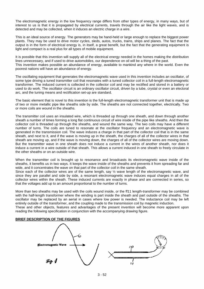
The electromagnetic energy in the low frequency range differs from other types of energy, in many ways, but of interest to us is that it is propagated by electrical currents, travels through the air like the light waves, and is detected and may be collected, when it induces an electric charge in a wire. This is an ideal source of energy. The generators may be hand-held or large enough to replace the biggest power plants. They may be used to drive motor cycles, sleds, autos, trucks, trains, ships and planes. The fact that the output is in the form of electrical energy is, in itself, a great benefit, but the fact that the generating equipment is light and compact is a real plus for all types of mobile equipment. It is possible that this invention will supply all of the electrical energy needed in the homes making the distribution lines unnecessary, and if used to drive automobiles, our dependence on oil will be a thing of the past. This invention makes possible an abundance of energy, available to mankind any where in the world. Even the poorest nations will have an abundance of energy. The oscillating equipment that generates the electromagnetic wave used in this invention includes an oscillator, of some type driving a tuned transmitter coil that resonates with a tuned collector coil in a full-length electromagnetic transformer. The induced current is collected in the collector coil and may be rectified and stored in a battery or used to do work. The oscillator circuit is an ordinary oscillator circuit, driven by a tube, crystal or even an electoral arc, and the tuning means and rectification set-up are standard. The basic element that is novel to this invention is the full-length electromagnetic transformer unit that is made up of two or more metallic pipe like sheaths side by side. The sheaths are not connected together, electrically. Two or more coils are wound in the sheaths. The transmitter coil uses an insulated wire, which is threaded up through one sheath, and down through another sheath a number of times forming a long flat continuous circuit of wire inside of the pipe like sheaths. And then the collector coil is threaded up through the sheaths, and wound the same way. The two coils may have a different number of turns. The coils are tuned to resonate at the oscillator frequency and an electromagnetic wave is generated in the transmission coil. The wave induces a charge in that part of the collector coil that is in the same sheath, and next to it, and if the wave is moving up in the sheath, the charges of all of the collector wires in that sheath are moving up, and if the wave is moving down, the charges of all of the collector wires are moving down. But the transmitter wave in one sheath does not induce a current in the wires of another sheath, nor does it induce a current in a wire outside of that sheath. This allows a current induced in one sheath to freely circulate in the other sheaths or on an outside wire. When the transmitter coil is brought up to resonance and broadcasts its electromagnetic wave inside of the sheaths, it benefits us in two ways. It keeps the wave inside of the sheaths and prevents it from spreading far and wide, and it concentrates the wave on that part of the collector coil in the same sheath. Since each of the collector wires are of the same length, say ½ wave length of the electromagnetic wave, and since they are parallel and side by side, a resonant electromagnetic wave induces equal charges in all of the collector wires within the sheath. These induced currents are exactly in phase and are connected in series, so that the voltages add up to an amount proportional to the number of turns. More than two sheaths may be used with the coils wound inside, or the ff11 length-transformer may be combined with the half-length transformer where the winding is part inside the sheath and part outside of the sheaths. The oscillator may be replaced by an aerial in cases where low power is needed. The inductance coil may be left entirely outside of the transformer, and the coupling made to the transmission coil by magnetic induction. These and other objects, features and advantages of the present invention will become more apparent upon reading the following specification in conjunction with the accompanying drawing figure. BRIEF DESCRIPTION OF THE FIGURES
3 - 52
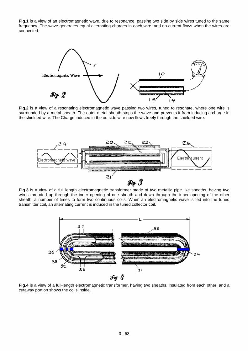
Fig.1 is a view of an electromagnetic wave, due to resonance, passing two side by side wires tuned to the same frequency. The wave generates equal alternating charges in each wire, and no current flows when the wires are connected.
Fig.2 is a view of a resonating electromagnetic wave passing two wires, tuned to resonate, where one wire is surrounded by a metal sheath. The outer metal sheath stops the wave and prevents it from inducing a charge in the shielded wire. The Charge induced in the outside wire now flows freely through the shielded wire.
Fig.3 is a view of a full length electromagnetic transformer made of two metallic pipe like sheaths, having two wires threaded up through the inner opening of one sheath and down through the inner opening of the other sheath, a number of times to form two continuous coils. When an electromagnetic wave is fed into the tuned transmitter coil, an alternating current is induced in the tuned collector coil.
Fig.4 is a view of a full-length electromagnetic transformer, having two sheaths, insulated from each other, and a cutaway portion shows the coils inside.
3 - 53
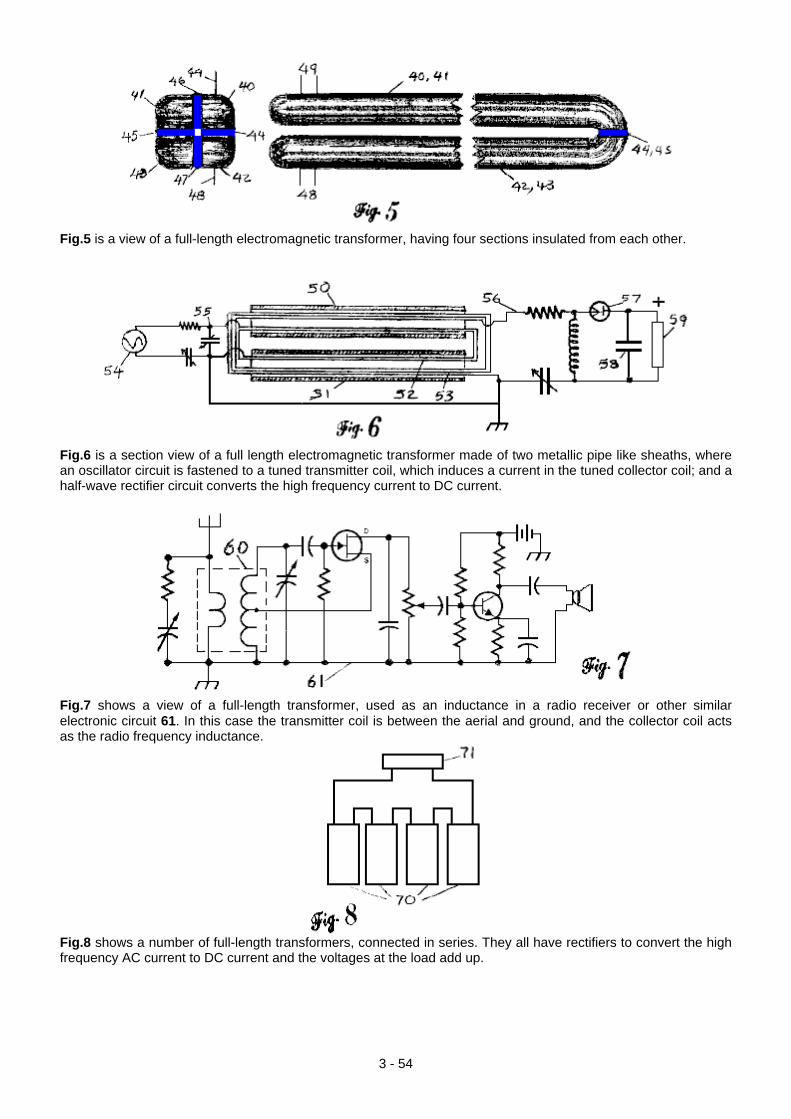
Fig.5 is a view of a full-length electromagnetic transformer, having four sections insulated from each other.
Fig.6 is a section view of a full length electromagnetic transformer made of two metallic pipe like sheaths, where an oscillator circuit is fastened to a tuned transmitter coil, which induces a current in the tuned collector coil; and a half-wave rectifier circuit converts the high frequency current to DC current.
Fig.7 shows a view of a full-length transformer, used as an inductance in a radio receiver or other similar electronic circuit 61. In this case the transmitter coil is between the aerial and ground, and the collector coil acts as the radio frequency inductance.
Fig.8 shows a number of full-length transformers, connected in series. They all have rectifiers to convert the high frequency AC current to DC current and the voltages at the load add up.
3 - 54
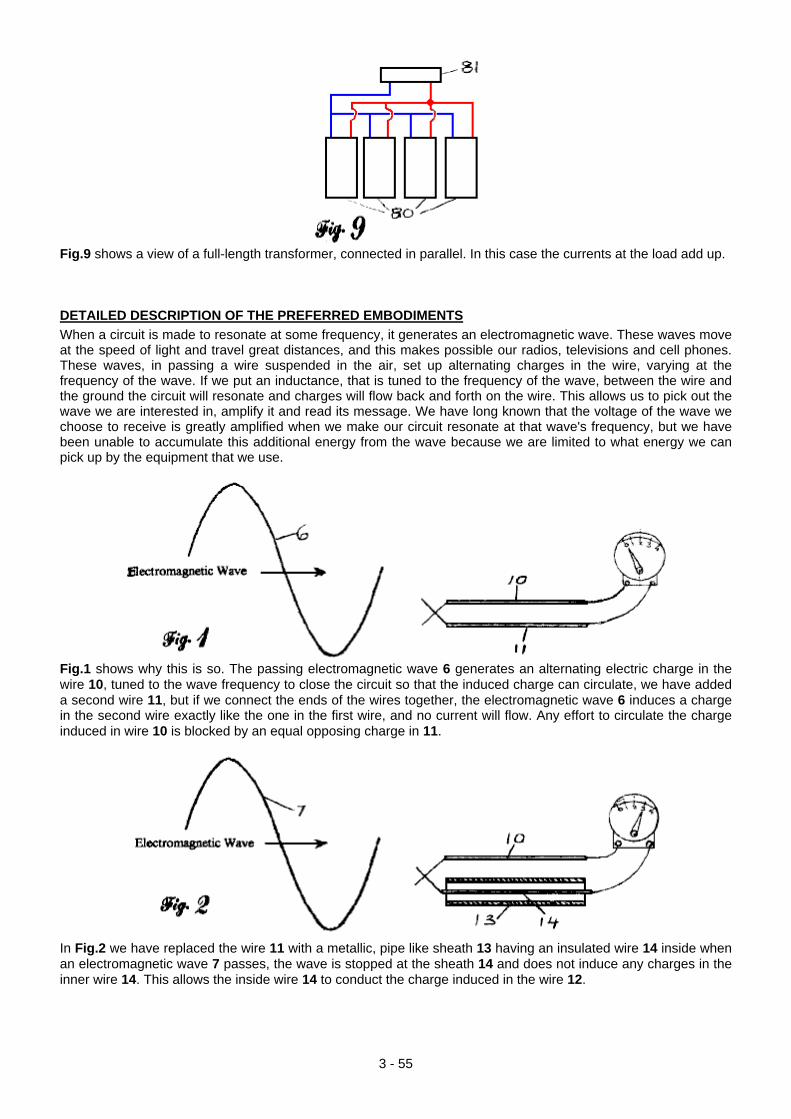
Fig.9 shows a view of a full-length transformer, connected in parallel. In this case the currents at the load add up. DETAILED DESCRIPTION OF THE PREFERRED EMBODIMENTS When a circuit is made to resonate at some frequency, it generates an electromagnetic wave. These waves move at the speed of light and travel great distances, and this makes possible our radios, televisions and cell phones. These waves, in passing a wire suspended in the air, set up alternating charges in the wire, varying at the frequency of the wave. If we put an inductance, that is tuned to the frequency of the wave, between the wire and the ground the circuit will resonate and charges will flow back and forth on the wire. This allows us to pick out the wave we are interested in, amplify it and read its message. We have long known that the voltage of the wave we choose to receive is greatly amplified when we make our circuit resonate at that wave's frequency, but we have been unable to accumulate this additional energy from the wave because we are limited to what energy we can pick up by the equipment that we use.
Fig.1 shows why this is so. The passing electromagnetic wave 6 generates an alternating electric charge in the wire 10, tuned to the wave frequency to close the circuit so that the induced charge can circulate, we have added a second wire 11, but if we connect the ends of the wires together, the electromagnetic wave 6 induces a charge in the second wire exactly like the one in the first wire, and no current will flow. Any effort to circulate the charge induced in wire 10 is blocked by an equal opposing charge in 11.
In Fig.2 we have replaced the wire 11 with a metallic, pipe like sheath 13 having an insulated wire 14 inside when an electromagnetic wave 7 passes, the wave is stopped at the sheath 14 and does not induce any charges in the inner wire 14. This allows the inside wire 14 to conduct the charge induced in the wire 12.
3 - 55
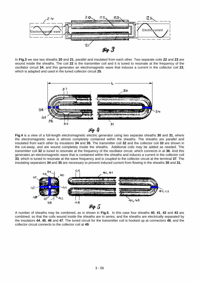
In Fig.3 we see two sheaths 20 and 21, parallel and insulated from each other. Two separate coils 22 and 23 are wound inside the sheaths. The coil 22 is the transmitter coil and it is tuned to resonate at the frequency of the oscillator circuit 24, and this generates an electromagnetic wave that induces a current in the collector coil 23, which is adapted and used in the tuned collector circuit 25.
Fig.4 is a view of a full-length electromagnetic electric generator using two separate sheaths 30 and 31, where the electromagnetic wave is almost completely contained within the sheaths. The sheaths are parallel and insulated from each other by insulators 34 and 35. The transmitter coil 32 and the collector coil 33 are shown in the cut-away, and are wound completely inside the sheaths. Additional coils may be added as needed. The transmitter coil 32 is tuned to resonate at the frequency of the oscillator circuit, which connects in at 36. And this generates an electromagnetic wave that is contained within the sheaths and induces a current in the collector coil 33, which is tuned to resonate at the wave frequency and is coupled to the collector circuit at the terminal 37. The insulating separators 34 and 35 are necessary to prevent induced current from flowing in the sheaths 30 and 31.
A number of sheaths may be combined, as is shown in Fig.5. In this case four sheaths 40, 41, 42 and 43 are combined, so that the coils wound inside the sheaths are in series, and the sheaths are electrically separated by the insulators 44, 45, 46 and 47. The tuned circuit for the transmitter coil is hooked up at connectors 48, and the collector circuit connects to the collector coil at 49.
3 - 56
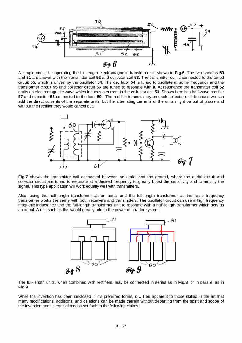
A simple circuit for operating the full-length electromagnetic transformer is shown in Fig.6. The two sheaths 50 and 51 are shown with the transmitter coil 52 and collector coil 53. The transmitter coil is connected to the tuned circuit 55, which is driven by the oscillator 54. The oscillator 54 is tuned to oscillate at some frequency and the transformer circuit 55 and collector circuit 56 are tuned to resonate with it. At resonance the transmitter coil 52 emits an electromagnetic wave which induces a current in the collector coil 53. Shown here is a half-wave rectifier 57 and capacitor 58 connected to the load 59. The rectifier is necessary on each collector unit, because we can add the direct currents of the separate units, but the alternating currents of the units might be out of phase and without the rectifier they would cancel out.
Fig.7 shows the transmitter coil connected between an aerial and the ground, where the aerial circuit and collector circuit are tuned to resonate at a desired frequency to greatly boost the sensitivity and to amplify the signal. This type application will work equally well with transmitters. Also, using the half-length transformer as an aerial and the full-length transformer as the radio frequency transformer works the same with both receivers and transmitters. The oscillator circuit can use a high frequency magnetic inductance and the full-length transformer unit to resonate with a half-length transformer which acts as an aerial. A unit such as this would greatly add to the power of a radar system.
The full-length units, when combined with rectifiers, may be connected in series as in Fig.8, or in parallel as in Fig.9 While the invention has been disclosed in it’s preferred forms, it will be apparent to those skilled in the art that many modifications, additions, and deletions can be made therein without departing from the spirit and scope of the invention and its equivalents as set forth in the following claims.
3 - 57
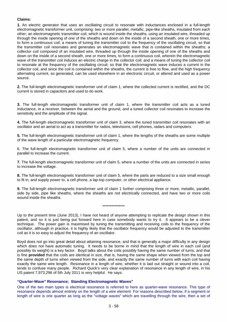
3 - 58
Claims: 1. An electric generator that uses an oscillating circuit to resonate with inductances enclosed in a full-length electromagnetic transformer unit, comprising: two or more parallel, metallic, pipe-like sheaths, insulated from each other; an electromagnetic transmitter coil, which is wound inside the sheaths, using an insulated wire, threaded up through the inside opening of one of the sheaths and down on the inside of a second sheath, one or more times, to form a continuous coil; a means of tuning the transmitter coil to the frequency of the oscillating circuit, so that the transmitter coil resonates and generates an electromagnetic wave that is contained within the sheaths; a collector coil composed of an insulated wire, threaded up through the inside opening of one of the sheaths and down on the inside of a second sheath, one or more times, to form a continuous coil, wherein the electromagnetic wave of the transmitter coil induces an electric charge in the collector coil; and a means of tuning the collector coil to resonate at the frequency of the oscillating circuit; so that the electromagnetic wave induces a current in the collector coil, and since the coil is contained within the sheaths, the current is free to flow, and the high frequency alternating current, so generated, can be used elsewhere in an electronic circuit, or altered and used as a power source. 2. The full-length electromagnetic transformer unit of claim 1, where the collected current is rectified, and the DC current is stored in capacitors and used to do work. 3. The full-length electromagnetic transformer unit of claim 1, where the transmitter coil acts as a tuned inductance, in a receiver, between the aerial and the ground, and a tuned collector coil resonates to increase the sensitivity and the amplitude of the signal. 4. The full-length electromagnetic transformer unit of claim 3, where the tuned transmitter coil resonates with an oscillator and an aerial to act as a transmitter for radios, televisions, cell phones, radars and computers. 5. The full-length electromagnetic transformer unit of claim 1, where the lengths of the sheaths are some multiple of the wave length of a particular electromagnetic frequency. 6. The full-length electromagnetic transformer unit of claim 5, where a number of the units are connected in parallel to increase the current. 7. The full-length electromagnetic transformer unit of claim 5, where a number of the units are connected in series to increase the voltage. 8. The full-length electromagnetic transformer unit of claim 5, where the parts are reduced to a size small enough to fit in, and supply power to, a cell phone, a lap-top computer, or other electrical appliance. 9. The full-length electromagnetic transformer unit of claim 1 further comprising three or more, metallic, parallel, side by side, pipe like sheaths, where the sheaths are not electrically connected, and have two or more coils wound inside the sheaths.
*************** Up to the present time (June 2013), I have not heard of anyone attempting to replicate the design shown in this patent, and so it is just being put forward here in case somebody wants to try it. It appears to be a clever technique. The power gain is maximised by tuning the transmitting and receiving coils to the frequency of the oscillator, although in practice, it is highly likely that the oscillator frequency would be adjusted to the transmitter coil as it is so easy to adjust the frequency of an oscillator. Boyd does not go into great detail about attaining resonance, and that is generally a major difficulty in any design which does not have automatic tuning. It needs to be borne in mind that the length of wire in each coil (and possibly its weight) is a key factor. Boyd talks about the coils possibly having the same number of turns, and that is fine provided that the coils are identical in size, that is, having the same shape when viewed from the top and the same depth of turns when viewed from the side, and exactly the same number of turns with each coil having exactly the same wire length. Resonance in a length of wire, whether it is laid out straight or wound into a coil, tends to confuse many people. Richard Quick’s very clear explanation of resonance in any length of wire, in his US patent 7,973,296 of 5th July 2011 is very helpful. He says: “Quarter-Wave” Resonance; Standing Electromagnetic Waves” One of the two main types is electrical resonance is referred to here as quarter-wave resonance. This type of resonance depends almost entirely on the length of a wire element For reasons described below, if a segment or length of wire is one quarter as long as the “voltage waves” which are travelling through the wire, then a set of
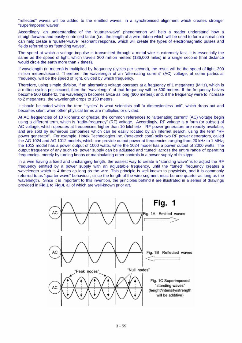
“reflected” waves will be added to the emitted waves, in a synchronised alignment which creates stronger “superimposed waves”. Accordingly, an understanding of the “quarter-wave” phenomenon will help a reader understand how a straightforward and easily-controlled factor (i.e., the length of a wire ribbon which will be used to form a spiral coil) can help create a “quarter-wave” resonant response, which will create the types of electromagnetic pulses and fields referred to as “standing waves”. The speed at which a voltage impulse is transmitted through a metal wire is extremely fast. It is essentially the same as the speed of light, which travels 300 million meters (186,000 miles) in a single second (that distance would circle the earth more than 7 times). If wavelength (in meters) is multiplied by frequency (cycles per second), the result will be the speed of light, 300 million meters/second. Therefore, the wavelength of an “alternating current” (AC) voltage, at some particular frequency, will be the speed of light, divided by which frequency. Therefore, using simple division, if an alternating voltage operates at a frequency of 1 megahertz (MHz), which is a million cycles per second, then the “wavelength” at that frequency will be 300 meters. If the frequency halves become 500 kilohertz, the wavelength becomes twice as long (600 meters); and, if the frequency were to increase to 2 megahertz, the wavelength drops to 150 meters. It should be noted which the term “cycles” is what scientists call “a dimensionless unit”, which drops out and becomes silent when other physical terms are multiplied or divided. At AC frequencies of 10 kilohertz or greater, the common references to “alternating current” (AC) voltage begin using a different term, which is “radio-frequency” (RF) voltage. Accordingly, RF voltage is a form (or subset) of AC voltage, which operates at frequencies higher than 10 kilohertz. RF power generators are readily available, and are sold by numerous companies which can be easily located by an Internet search, using the term “RF power generator”. For example, Hotek Technologies Inc. (hotektech.com) sells two RF power generators, called the AG 1024 and AG 1012 models, which can provide output power at frequencies ranging from 20 kHz to 1 MHz; the 1012 model has a power output of 1000 watts, while the 1024 model has a power output of 2000 watts. The output frequency of any such RF power supply can be adjusted and “tuned” across the entire range of operating frequencies, merely by turning knobs or manipulating other controls in a power supply of this type. In a wire having a fixed and unchanging length, the easiest way to create a “standing wave” is to adjust the RF frequency emitted by a power supply with an adjustable frequency, until the “tuned” frequency creates a wavelength which is 4 times as long as the wire. This principle is well-known to physicists, and it is commonly referred to as “quarter-wave” behaviour, since the length of the wire segment must be one quarter as long as the wavelength. Since it is important to this invention, the principles behind it are illustrated in a series of drawings provided in Fig.1 to Fig.4, all of which are well-known prior art.
3 - 59
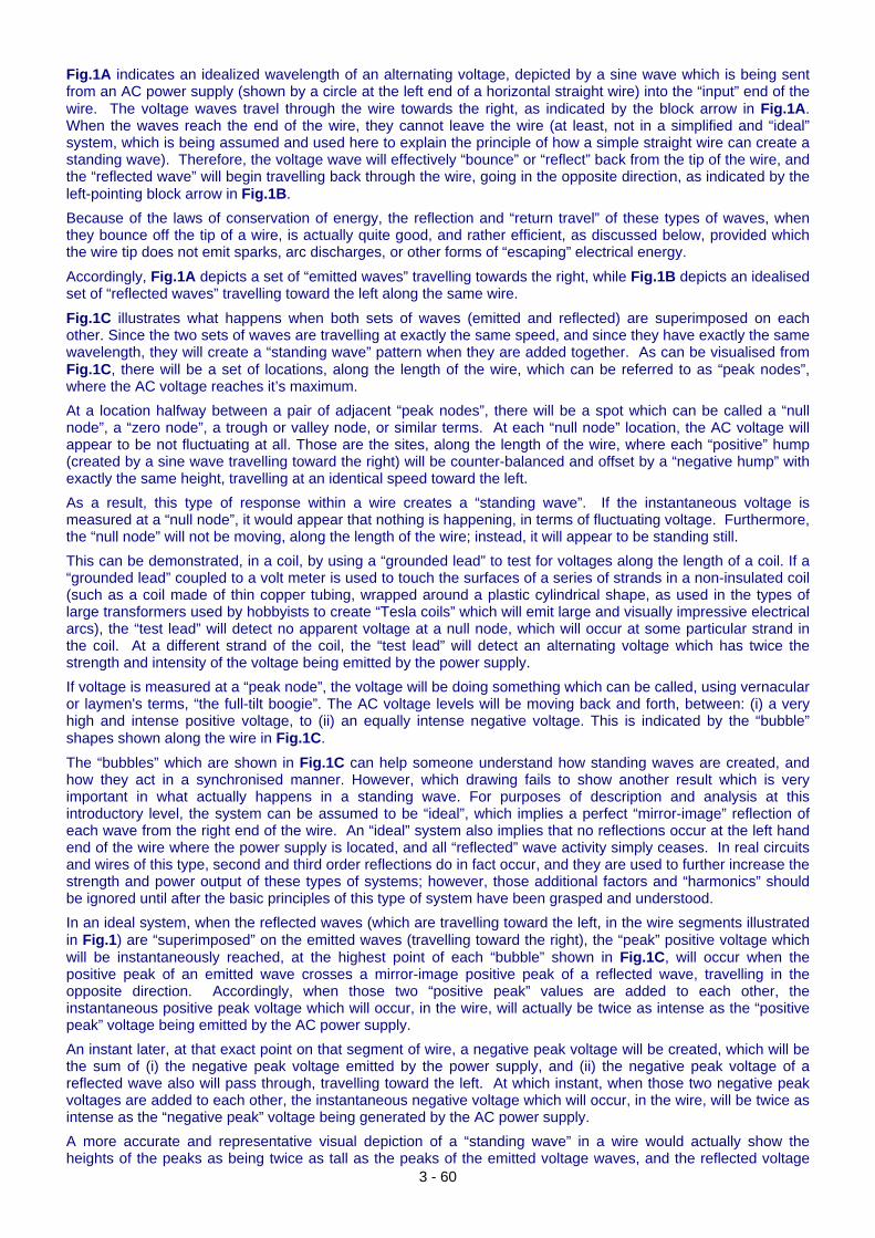
3 - 60
Fig.1A indicates an idealized wavelength of an alternating voltage, depicted by a sine wave which is being sent from an AC power supply (shown by a circle at the left end of a horizontal straight wire) into the “input” end of the wire. The voltage waves travel through the wire towards the right, as indicated by the block arrow in Fig.1A. When the waves reach the end of the wire, they cannot leave the wire (at least, not in a simplified and “ideal” system, which is being assumed and used here to explain the principle of how a simple straight wire can create a standing wave). Therefore, the voltage wave will effectively “bounce” or “reflect” back from the tip of the wire, and the “reflected wave” will begin travelling back through the wire, going in the opposite direction, as indicated by the left-pointing block arrow in Fig.1B. Because of the laws of conservation of energy, the reflection and “return travel” of these types of waves, when they bounce off the tip of a wire, is actually quite good, and rather efficient, as discussed below, provided which the wire tip does not emit sparks, arc discharges, or other forms of “escaping” electrical energy.
Accordingly, Fig.1A depicts a set of “emitted waves” travelling towards the right, while Fig.1B depicts an idealised set of “reflected waves” travelling toward the left along the same wire.
Fig.1C illustrates what happens when both sets of waves (emitted and reflected) are superimposed on each other. Since the two sets of waves are travelling at exactly the same speed, and since they have exactly the same wavelength, they will create a “standing wave” pattern when they are added together. As can be visualised from Fig.1C, there will be a set of locations, along the length of the wire, which can be referred to as “peak nodes”, where the AC voltage reaches it’s maximum. At a location halfway between a pair of adjacent “peak nodes”, there will be a spot which can be called a “null node”, a “zero node”, a trough or valley node, or similar terms. At each “null node” location, the AC voltage will appear to be not fluctuating at all. Those are the sites, along the length of the wire, where each “positive” hump (created by a sine wave travelling toward the right) will be counter-balanced and offset by a “negative hump” with exactly the same height, travelling at an identical speed toward the left. As a result, this type of response within a wire creates a “standing wave”. If the instantaneous voltage is measured at a “null node”, it would appear that nothing is happening, in terms of fluctuating voltage. Furthermore, the “null node” will not be moving, along the length of the wire; instead, it will appear to be standing still. This can be demonstrated, in a coil, by using a “grounded lead” to test for voltages along the length of a coil. If a “grounded lead” coupled to a volt meter is used to touch the surfaces of a series of strands in a non-insulated coil (such as a coil made of thin copper tubing, wrapped around a plastic cylindrical shape, as used in the types of large transformers used by hobbyists to create “Tesla coils” which will emit large and visually impressive electrical arcs), the “test lead” will detect no apparent voltage at a null node, which will occur at some particular strand in the coil. At a different strand of the coil, the “test lead” will detect an alternating voltage which has twice the strength and intensity of the voltage being emitted by the power supply. If voltage is measured at a “peak node”, the voltage will be doing something which can be called, using vernacular or laymen's terms, “the full-tilt boogie”. The AC voltage levels will be moving back and forth, between: (i) a very high and intense positive voltage, to (ii) an equally intense negative voltage. This is indicated by the “bubble” shapes shown along the wire in Fig.1C.
The “bubbles” which are shown in Fig.1C can help someone understand how standing waves are created, and how they act in a synchronised manner. However, which drawing fails to show another result which is very important in what actually happens in a standing wave. For purposes of description and analysis at this introductory level, the system can be assumed to be “ideal”, which implies a perfect “mirror-image” reflection of each wave from the right end of the wire. An “ideal” system also implies that no reflections occur at the left hand end of the wire where the power supply is located, and all “reflected” wave activity simply ceases. In real circuits and wires of this type, second and third order reflections do in fact occur, and they are used to further increase the strength and power output of these types of systems; however, those additional factors and “harmonics” should be ignored until after the basic principles of this type of system have been grasped and understood. In an ideal system, when the reflected waves (which are travelling toward the left, in the wire segments illustrated in Fig.1) are “superimposed” on the emitted waves (travelling toward the right), the “peak” positive voltage which will be instantaneously reached, at the highest point of each “bubble” shown in Fig.1C, will occur when the positive peak of an emitted wave crosses a mirror-image positive peak of a reflected wave, travelling in the opposite direction. Accordingly, when those two “positive peak” values are added to each other, the instantaneous positive peak voltage which will occur, in the wire, will actually be twice as intense as the “positive peak” voltage being emitted by the AC power supply. An instant later, at that exact point on that segment of wire, a negative peak voltage will be created, which will be the sum of (i) the negative peak voltage emitted by the power supply, and (ii) the negative peak voltage of a reflected wave also will pass through, travelling toward the left. At which instant, when those two negative peak voltages are added to each other, the instantaneous negative voltage which will occur, in the wire, will be twice as intense as the “negative peak” voltage being generated by the AC power supply. A more accurate and representative visual depiction of a “standing wave” in a wire would actually show the heights of the peaks as being twice as tall as the peaks of the emitted voltage waves, and the reflected voltage
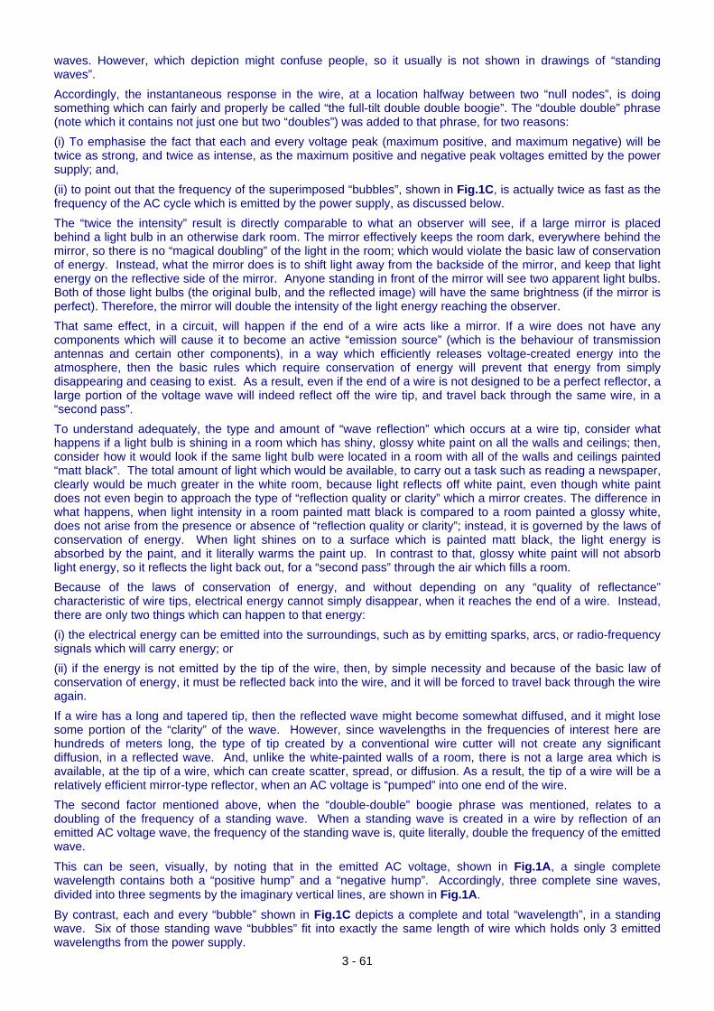
3 - 61
waves. However, which depiction might confuse people, so it usually is not shown in drawings of “standing waves”. Accordingly, the instantaneous response in the wire, at a location halfway between two “null nodes”, is doing something which can fairly and properly be called “the full-tilt double double boogie”. The “double double” phrase (note which it contains not just one but two “doubles”) was added to that phrase, for two reasons: (i) To emphasise the fact that each and every voltage peak (maximum positive, and maximum negative) will be twice as strong, and twice as intense, as the maximum positive and negative peak voltages emitted by the power supply; and,
(ii) to point out that the frequency of the superimposed “bubbles”, shown in Fig.1C, is actually twice as fast as the frequency of the AC cycle which is emitted by the power supply, as discussed below. The “twice the intensity” result is directly comparable to what an observer will see, if a large mirror is placed behind a light bulb in an otherwise dark room. The mirror effectively keeps the room dark, everywhere behind the mirror, so there is no “magical doubling” of the light in the room; which would violate the basic law of conservation of energy. Instead, what the mirror does is to shift light away from the backside of the mirror, and keep that light energy on the reflective side of the mirror. Anyone standing in front of the mirror will see two apparent light bulbs. Both of those light bulbs (the original bulb, and the reflected image) will have the same brightness (if the mirror is perfect). Therefore, the mirror will double the intensity of the light energy reaching the observer. That same effect, in a circuit, will happen if the end of a wire acts like a mirror. If a wire does not have any components which will cause it to become an active “emission source” (which is the behaviour of transmission antennas and certain other components), in a way which efficiently releases voltage-created energy into the atmosphere, then the basic rules which require conservation of energy will prevent that energy from simply disappearing and ceasing to exist. As a result, even if the end of a wire is not designed to be a perfect reflector, a large portion of the voltage wave will indeed reflect off the wire tip, and travel back through the same wire, in a “second pass”. To understand adequately, the type and amount of “wave reflection” which occurs at a wire tip, consider what happens if a light bulb is shining in a room which has shiny, glossy white paint on all the walls and ceilings; then, consider how it would look if the same light bulb were located in a room with all of the walls and ceilings painted “matt black”. The total amount of light which would be available, to carry out a task such as reading a newspaper, clearly would be much greater in the white room, because light reflects off white paint, even though white paint does not even begin to approach the type of “reflection quality or clarity” which a mirror creates. The difference in what happens, when light intensity in a room painted matt black is compared to a room painted a glossy white, does not arise from the presence or absence of “reflection quality or clarity”; instead, it is governed by the laws of conservation of energy. When light shines on to a surface which is painted matt black, the light energy is absorbed by the paint, and it literally warms the paint up. In contrast to that, glossy white paint will not absorb light energy, so it reflects the light back out, for a “second pass” through the air which fills a room. Because of the laws of conservation of energy, and without depending on any “quality of reflectance” characteristic of wire tips, electrical energy cannot simply disappear, when it reaches the end of a wire. Instead, there are only two things which can happen to that energy: (i) the electrical energy can be emitted into the surroundings, such as by emitting sparks, arcs, or radio-frequency signals which will carry energy; or (ii) if the energy is not emitted by the tip of the wire, then, by simple necessity and because of the basic law of conservation of energy, it must be reflected back into the wire, and it will be forced to travel back through the wire again. If a wire has a long and tapered tip, then the reflected wave might become somewhat diffused, and it might lose some portion of the “clarity” of the wave. However, since wavelengths in the frequencies of interest here are hundreds of meters long, the type of tip created by a conventional wire cutter will not create any significant diffusion, in a reflected wave. And, unlike the white-painted walls of a room, there is not a large area which is available, at the tip of a wire, which can create scatter, spread, or diffusion. As a result, the tip of a wire will be a relatively efficient mirror-type reflector, when an AC voltage is “pumped” into one end of the wire. The second factor mentioned above, when the “double-double” boogie phrase was mentioned, relates to a doubling of the frequency of a standing wave. When a standing wave is created in a wire by reflection of an emitted AC voltage wave, the frequency of the standing wave is, quite literally, double the frequency of the emitted wave.
This can be seen, visually, by noting that in the emitted AC voltage, shown in Fig.1A, a single complete wavelength contains both a “positive hump” and a “negative hump”. Accordingly, three complete sine waves, divided into three segments by the imaginary vertical lines, are shown in Fig.1A.
By contrast, each and every “bubble” shown in Fig.1C depicts a complete and total “wavelength”, in a standing wave. Six of those standing wave “bubbles” fit into exactly the same length of wire which holds only 3 emitted wavelengths from the power supply.
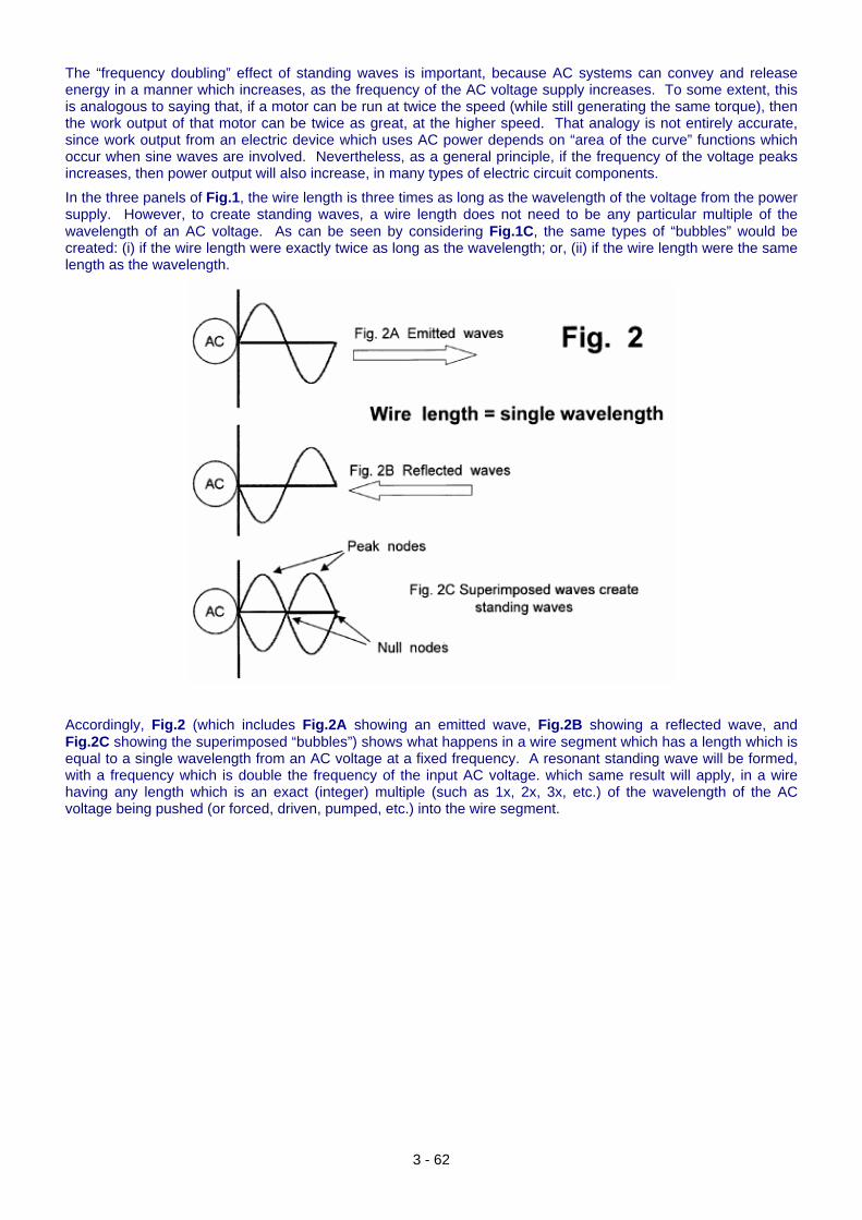
The “frequency doubling” effect of standing waves is important, because AC systems can convey and release energy in a manner which increases, as the frequency of the AC voltage supply increases. To some extent, this is analogous to saying that, if a motor can be run at twice the speed (while still generating the same torque), then the work output of that motor can be twice as great, at the higher speed. That analogy is not entirely accurate, since work output from an electric device which uses AC power depends on “area of the curve” functions which occur when sine waves are involved. Nevertheless, as a general principle, if the frequency of the voltage peaks increases, then power output will also increase, in many types of electric circuit components.
In the three panels of Fig.1, the wire length is three times as long as the wavelength of the voltage from the power supply. However, to create standing waves, a wire length does not need to be any particular multiple of the wavelength of an AC voltage. As can be seen by considering Fig.1C, the same types of “bubbles” would be created: (i) if the wire length were exactly twice as long as the wavelength; or, (ii) if the wire length were the same length as the wavelength.
Accordingly, Fig.2 (which includes Fig.2A showing an emitted wave, Fig.2B showing a reflected wave, and Fig.2C showing the superimposed “bubbles”) shows what happens in a wire segment which has a length which is equal to a single wavelength from an AC voltage at a fixed frequency. A resonant standing wave will be formed, with a frequency which is double the frequency of the input AC voltage. which same result will apply, in a wire having any length which is an exact (integer) multiple (such as 1x, 2x, 3x, etc.) of the wavelength of the AC voltage being pushed (or forced, driven, pumped, etc.) into the wire segment.
3 - 62
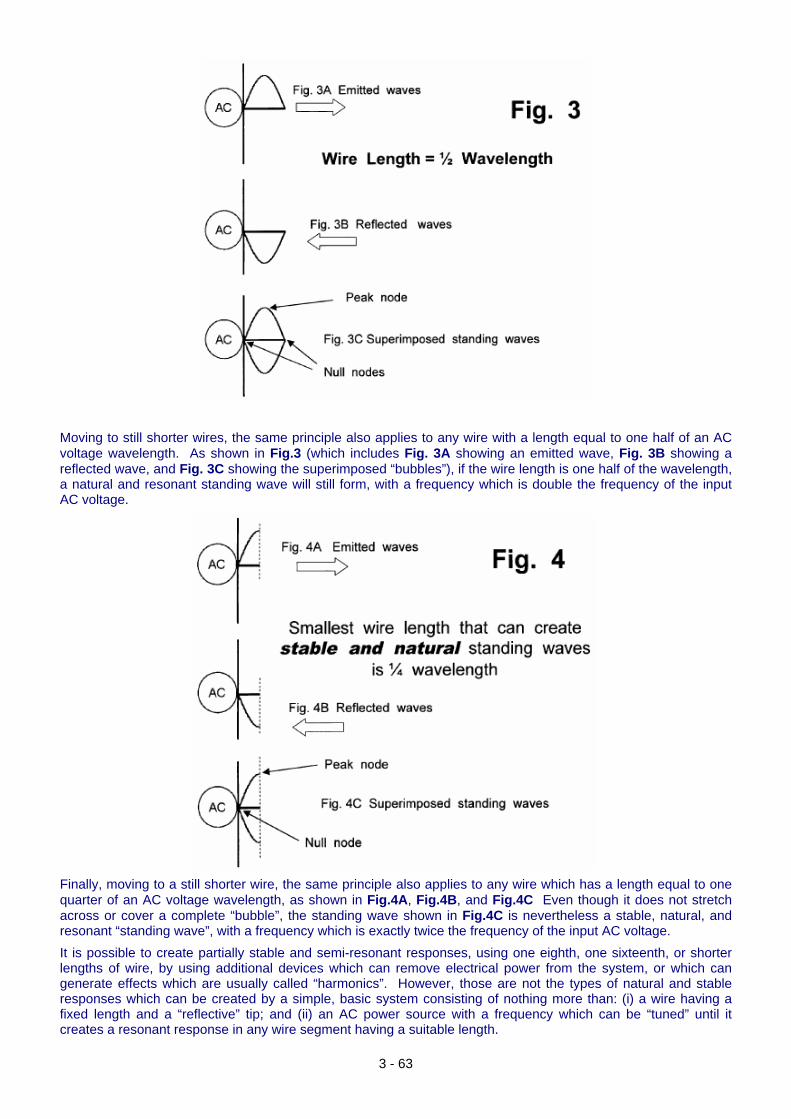
Moving to still shorter wires, the same principle also applies to any wire with a length equal to one half of an AC voltage wavelength. As shown in Fig.3 (which includes Fig. 3A showing an emitted wave, Fig. 3B showing a reflected wave, and Fig. 3C showing the superimposed “bubbles”), if the wire length is one half of the wavelength, a natural and resonant standing wave will still form, with a frequency which is double the frequency of the input AC voltage.
Finally, moving to a still shorter wire, the same principle also applies to any wire which has a length equal to one quarter of an AC voltage wavelength, as shown in Fig.4A, Fig.4B, and Fig.4C Even though it does not stretch across or cover a complete “bubble”, the standing wave shown in Fig.4C is nevertheless a stable, natural, and resonant “standing wave”, with a frequency which is exactly twice the frequency of the input AC voltage. It is possible to create partially stable and semi-resonant responses, using one eighth, one sixteenth, or shorter lengths of wire, by using additional devices which can remove electrical power from the system, or which can generate effects which are usually called “harmonics”. However, those are not the types of natural and stable responses which can be created by a simple, basic system consisting of nothing more than: (i) a wire having a fixed length and a “reflective” tip; and (ii) an AC power source with a frequency which can be “tuned” until it creates a resonant response in any wire segment having a suitable length.
3 - 63
Therefore, since quarter-wave wire lengths are the shortest lengths which can create natural and stable standing waves, the conventional term which is commonly used, to describe what happens when a wire creates a resonant standing-wave response, is a “quarter-wave” response. In some devices, telescoping components (or other elements which can alter the effective length of a wire-type element) can be used to alter the ability of the element to respond to a fixed wavelength. Many types of antennas use this approach, if they need to process signals which are being transmitted on fixed and known frequencies. However, those examples are not relevant to spiral coil reactors, which will use an approach which involves tuning and adjusting the frequency of the voltage which is being supplied to a reactor, until a resonant response is observed in coils with fixed and unchanging lengths. It should also be noted that certain types of “tuning” elements (such as capacitors, which can have either fixed or adjustable capacitance levels) can also be coupled electrically to a wire, in a manner which “emulates” adding more length to that wire. This approach can be used to alter (or increase the range of) the frequencies to which a wire circuit will respond resonantly.
The ‘Gegene’ Magnetic Arrangement. As we have seen from what Don Smith has said, a very effective method of gaining additional power is to make a high frequency magnetic transmitter as that allows several outputs to be taken from the transmitter without increasing the input power in any way. Recently, a clever idea for a simplified version of this has been shared on the web. As far as I am aware, this device was first presented by the Lithuanian ‘FreeEnergyLT’ whose website is at http://freeenergylt.narod2.ru/dynatron/
and the information then replicated and documented by J L Naudin on his website http://jnaudin.free.fr/gegene/indexen.htm and named ‘Gegene’ being short for ‘Great Efficiency Generator’. The clever idea is to use a commercial induction hot-plate as the transmitter. These have recently become available at low cost, this one:
3 - 64
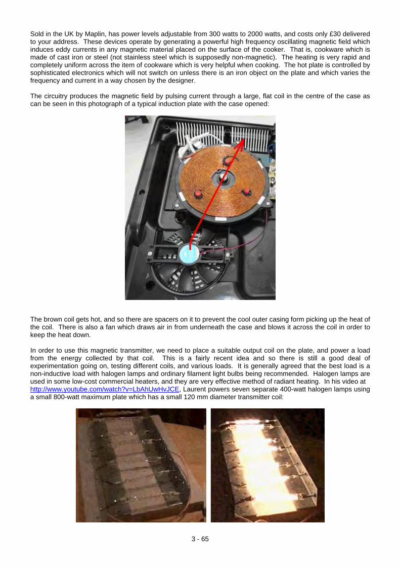
Sold in the UK by Maplin, has power levels adjustable from 300 watts to 2000 watts, and costs only £30 delivered to your address. These devices operate by generating a powerful high frequency oscillating magnetic field which induces eddy currents in any magnetic material placed on the surface of the cooker. That is, cookware which is made of cast iron or steel (not stainless steel which is supposedly non-magnetic). The heating is very rapid and completely uniform across the item of cookware which is very helpful when cooking. The hot plate is controlled by sophisticated electronics which will not switch on unless there is an iron object on the plate and which varies the frequency and current in a way chosen by the designer. The circuitry produces the magnetic field by pulsing current through a large, flat coil in the centre of the case as can be seen in this photograph of a typical induction plate with the case opened:
The brown coil gets hot, and so there are spacers on it to prevent the cool outer casing form picking up the heat of the coil. There is also a fan which draws air in from underneath the case and blows it across the coil in order to keep the heat down. In order to use this magnetic transmitter, we need to place a suitable output coil on the plate, and power a load from the energy collected by that coil. This is a fairly recent idea and so there is still a good deal of experimentation going on, testing different coils, and various loads. It is generally agreed that the best load is a non-inductive load with halogen lamps and ordinary filament light bulbs being recommended. Halogen lamps are used in some low-cost commercial heaters, and they are very effective method of radiant heating. In his video at http://www.youtube.com/watch?v=LbAhUwHvJCE, Laurent powers seven separate 400-watt halogen lamps using a small 800-watt maximum plate which has a small 120 mm diameter transmitter coil:
3 - 65
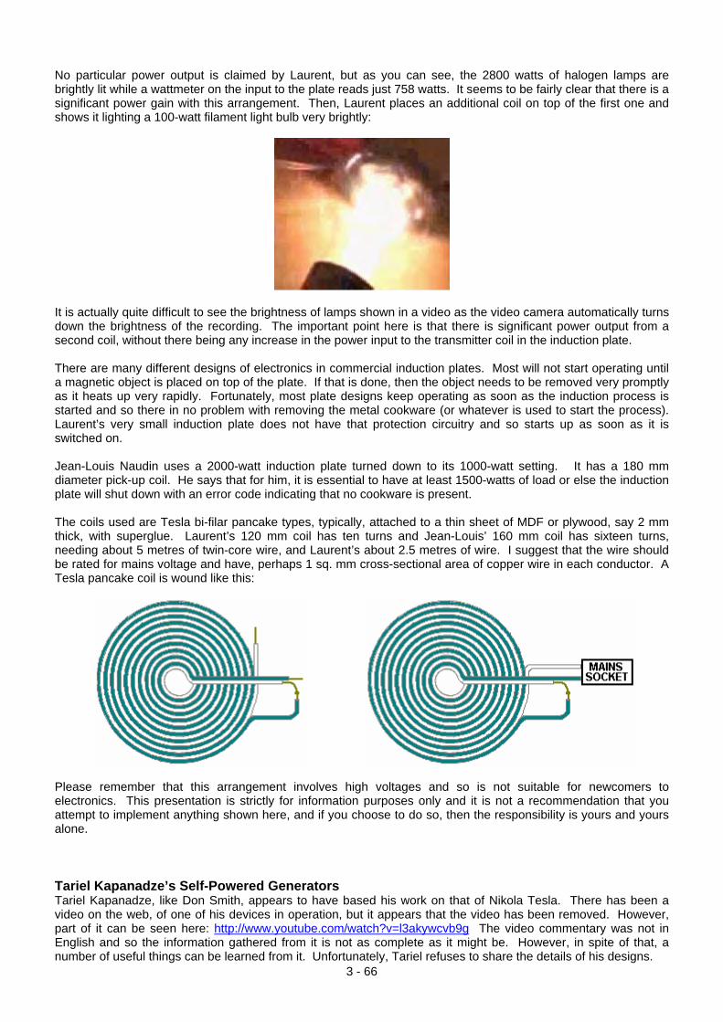
No particular power output is claimed by Laurent, but as you can see, the 2800 watts of halogen lamps are brightly lit while a wattmeter on the input to the plate reads just 758 watts. It seems to be fairly clear that there is a significant power gain with this arrangement. Then, Laurent places an additional coil on top of the first one and shows it lighting a 100-watt filament light bulb very brightly:
It is actually quite difficult to see the brightness of lamps shown in a video as the video camera automatically turns down the brightness of the recording. The important point here is that there is significant power output from a second coil, without there being any increase in the power input to the transmitter coil in the induction plate. There are many different designs of electronics in commercial induction plates. Most will not start operating until a magnetic object is placed on top of the plate. If that is done, then the object needs to be removed very promptly as it heats up very rapidly. Fortunately, most plate designs keep operating as soon as the induction process is started and so there in no problem with removing the metal cookware (or whatever is used to start the process). Laurent’s very small induction plate does not have that protection circuitry and so starts up as soon as it is switched on. Jean-Louis Naudin uses a 2000-watt induction plate turned down to its 1000-watt setting. It has a 180 mm diameter pick-up coil. He says that for him, it is essential to have at least 1500-watts of load or else the induction plate will shut down with an error code indicating that no cookware is present. The coils used are Tesla bi-filar pancake types, typically, attached to a thin sheet of MDF or plywood, say 2 mm thick, with superglue. Laurent’s 120 mm coil has ten turns and Jean-Louis’ 160 mm coil has sixteen turns, needing about 5 metres of twin-core wire, and Laurent’s about 2.5 metres of wire. I suggest that the wire should be rated for mains voltage and have, perhaps 1 sq. mm cross-sectional area of copper wire in each conductor. A Tesla pancake coil is wound like this:
Please remember that this arrangement involves high voltages and so is not suitable for newcomers to electronics. This presentation is strictly for information purposes only and it is not a recommendation that you attempt to implement anything shown here, and if you choose to do so, then the responsibility is yours and yours alone. Tariel Kapanadze’s Self-Powered Generators
3 - 66
Tariel Kapanadze, like Don Smith, appears to have based his work on that of Nikola Tesla. There has been a video on the web, of one of his devices in operation, but it appears that the video has been removed. However, part of it can be seen here: http://www.youtube.com/watch?v=l3akywcvb9g The video commentary was not in English and so the information gathered from it is not as complete as it might be. However, in spite of that, a number of useful things can be learned from it. Unfortunately, Tariel refuses to share the details of his designs.

The video shows a demonstration being staged in a back garden, I believe, in Turkey. Strong sunshine was casting dense shadows which made video detail less than perfect. Essentially, Tariel demonstrated one of his builds of a Tesla-style free-energy device, powering both itself and a row of five light bulbs. One of the most encouraging things about this video is that the construction and operation was of the most basic kind, with not the slightest suggestion of expensive laboratory work or anything high-precision. This is most definitely a backyard construction within the scope of any knowledgeable person. Electrical connections were made by twisting bare wires together:
and where necessary, tightening the twist with a pair of pliers:
This shows clearly that a high-power and very useful free-energy device can be made with the most simple of construction methods - no expensive connectors here, just a zero-cost twisted connection.
3 - 67
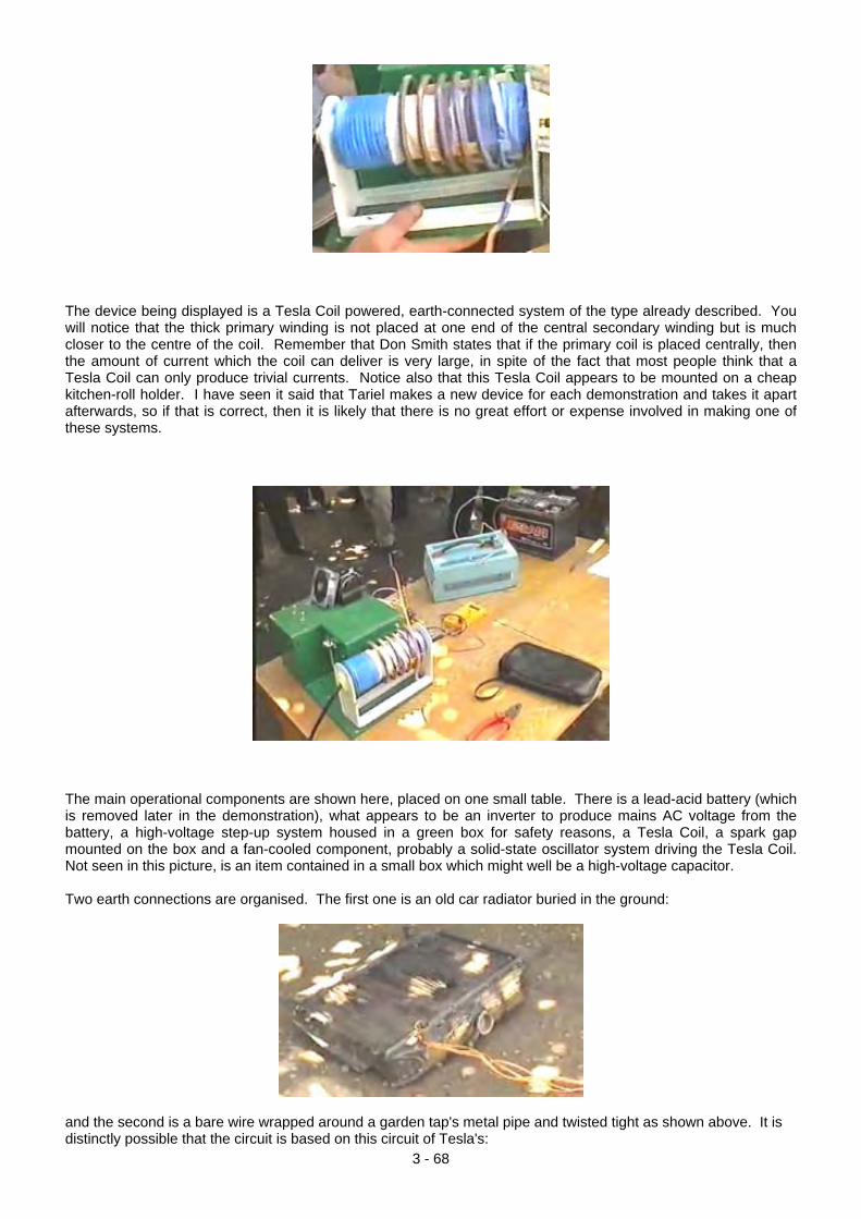
The device being displayed is a Tesla Coil powered, earth-connected system of the type already described. You will notice that the thick primary winding is not placed at one end of the central secondary winding but is much closer to the centre of the coil. Remember that Don Smith states that if the primary coil is placed centrally, then the amount of current which the coil can deliver is very large, in spite of the fact that most people think that a Tesla Coil can only produce trivial currents. Notice also that this Tesla Coil appears to be mounted on a cheap kitchen-roll holder. I have seen it said that Tariel makes a new device for each demonstration and takes it apart afterwards, so if that is correct, then it is likely that there is no great effort or expense involved in making one of these systems.
The main operational components are shown here, placed on one small table. There is a lead-acid battery (which is removed later in the demonstration), what appears to be an inverter to produce mains AC voltage from the battery, a high-voltage step-up system housed in a green box for safety reasons, a Tesla Coil, a spark gap mounted on the box and a fan-cooled component, probably a solid-state oscillator system driving the Tesla Coil. Not seen in this picture, is an item contained in a small box which might well be a high-voltage capacitor. Two earth connections are organised. The first one is an old car radiator buried in the ground:
and the second is a bare wire wrapped around a garden tap's metal pipe and twisted tight as shown above. It is distinctly possible that the circuit is based on this circuit of Tesla's:
3 - 68
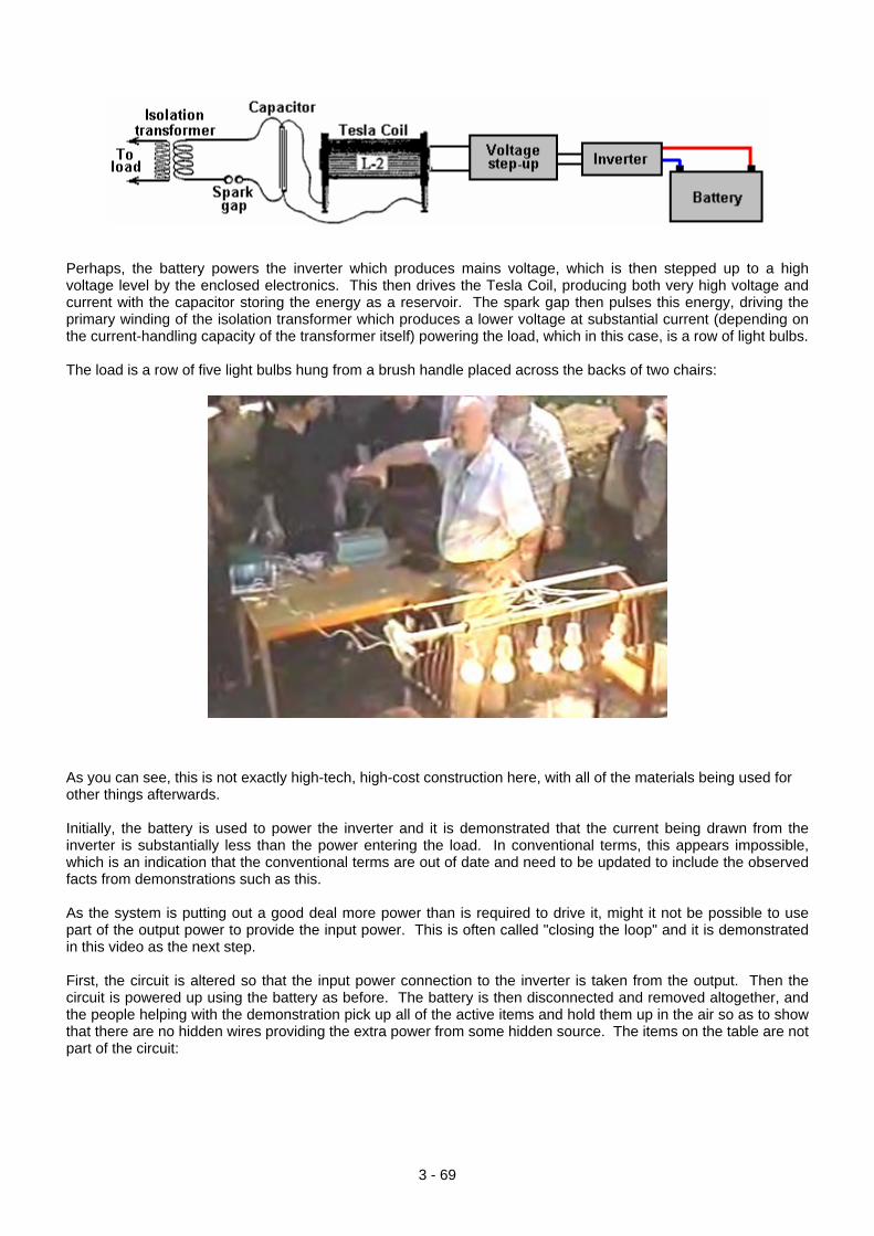
Perhaps, the battery powers the inverter which produces mains voltage, which is then stepped up to a high voltage level by the enclosed electronics. This then drives the Tesla Coil, producing both very high voltage and current with the capacitor storing the energy as a reservoir. The spark gap then pulses this energy, driving the primary winding of the isolation transformer which produces a lower voltage at substantial current (depending on the current-handling capacity of the transformer itself) powering the load, which in this case, is a row of light bulbs. The load is a row of five light bulbs hung from a brush handle placed across the backs of two chairs:
As you can see, this is not exactly high-tech, high-cost construction here, with all of the materials being used for other things afterwards. Initially, the battery is used to power the inverter and it is demonstrated that the current being drawn from the inverter is substantially less than the power entering the load. In conventional terms, this appears impossible, which is an indication that the conventional terms are out of date and need to be updated to include the observed facts from demonstrations such as this. As the system is putting out a good deal more power than is required to drive it, might it not be possible to use part of the output power to provide the input power. This is often called "closing the loop" and it is demonstrated in this video as the next step. First, the circuit is altered so that the input power connection to the inverter is taken from the output. Then the circuit is powered up using the battery as before. The battery is then disconnected and removed altogether, and the people helping with the demonstration pick up all of the active items and hold them up in the air so as to show that there are no hidden wires providing the extra power from some hidden source. The items on the table are not part of the circuit:
3 - 69
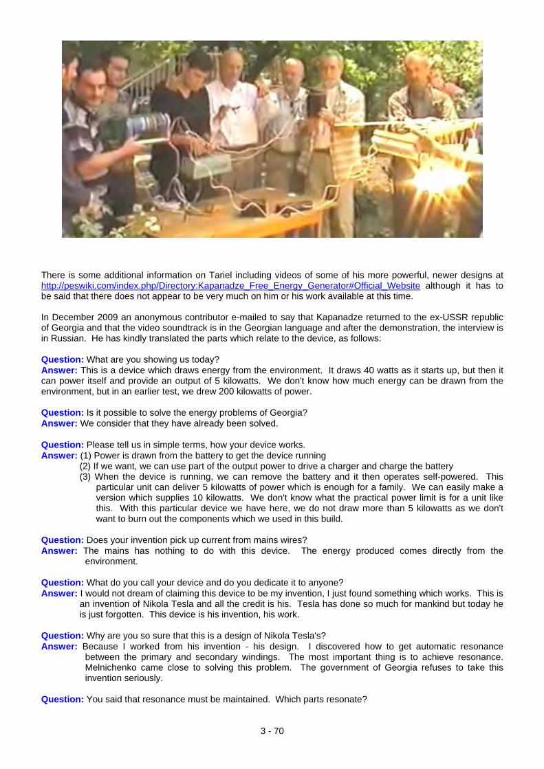
There is some additional information on Tariel including videos of some of his more powerful, newer designs at http://peswiki.com/index.php/Directory:Kapanadze_Free_Energy_Generator#Official_Website although it has to be said that there does not appear to be very much on him or his work available at this time. In December 2009 an anonymous contributor e-mailed to say that Kapanadze returned to the ex-USSR republic of Georgia and that the video soundtrack is in the Georgian language and after the demonstration, the interview is in Russian. He has kindly translated the parts which relate to the device, as follows: Question: What are you showing us today? Answer: This is a device which draws energy from the environment. It draws 40 watts as it starts up, but then it can power itself and provide an output of 5 kilowatts. We don't know how much energy can be drawn from the environment, but in an earlier test, we drew 200 kilowatts of power. Question: Is it possible to solve the energy problems of Georgia? Answer: We consider that they have already been solved. Question: Please tell us in simple terms, how your device works. Answer: (1) Power is drawn from the battery to get the device running
(2) If we want, we can use part of the output power to drive a charger and charge the battery (3) When the device is running, we can remove the battery and it then operates self-powered. This
particular unit can deliver 5 kilowatts of power which is enough for a family. We can easily make a version which supplies 10 kilowatts. We don't know what the practical power limit is for a unit like this. With this particular device we have here, we do not draw more than 5 kilowatts as we don't want to burn out the components which we used in this build.
Question: Does your invention pick up current from mains wires? Answer: The mains has nothing to do with this device. The energy produced comes directly from the
environment. Question: What do you call your device and do you dedicate it to anyone? Answer: I would not dream of claiming this device to be my invention, I just found something which works. This is
an invention of Nikola Tesla and all the credit is his. Tesla has done so much for mankind but today he is just forgotten. This device is his invention, his work.
Question: Why are you so sure that this is a design of Nikola Tesla's? Answer: Because I worked from his invention - his design. I discovered how to get automatic resonance
between the primary and secondary windings. The most important thing is to achieve resonance. Melnichenko came close to solving this problem. The government of Georgia refuses to take this invention seriously.
Question: You said that resonance must be maintained. Which parts resonate?
3 - 70
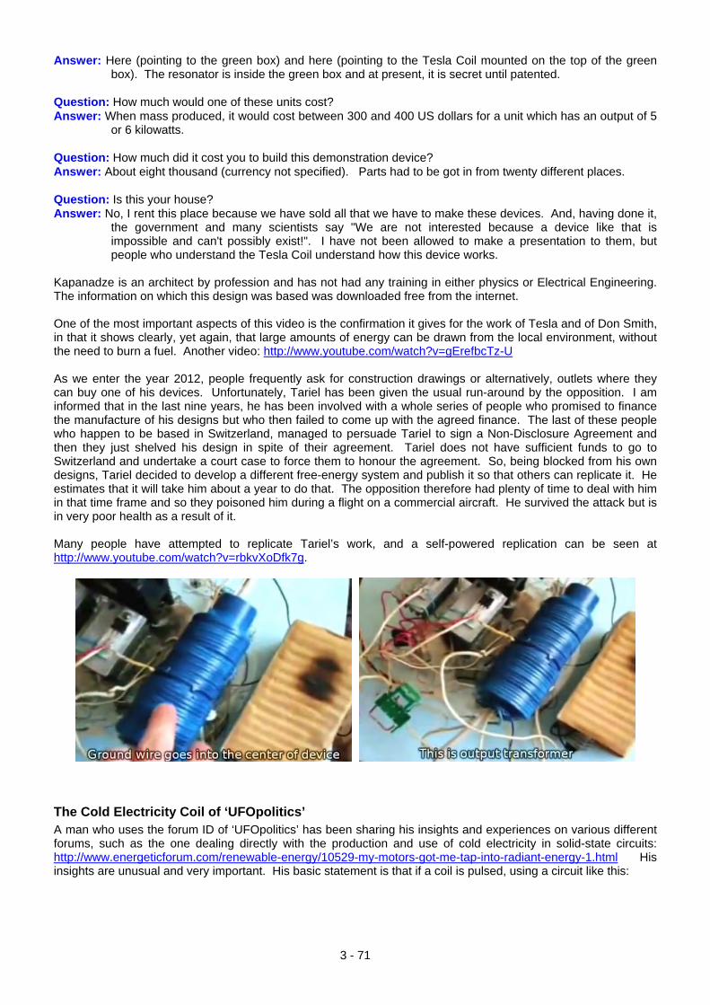
Answer: Here (pointing to the green box) and here (pointing to the Tesla Coil mounted on the top of the green box). The resonator is inside the green box and at present, it is secret until patented.
Question: How much would one of these units cost? Answer: When mass produced, it would cost between 300 and 400 US dollars for a unit which has an output of 5
or 6 kilowatts. Question: How much did it cost you to build this demonstration device? Answer: About eight thousand (currency not specified). Parts had to be got in from twenty different places. Question: Is this your house? Answer: No, I rent this place because we have sold all that we have to make these devices. And, having done it,
the government and many scientists say "We are not interested because a device like that is impossible and can't possibly exist!". I have not been allowed to make a presentation to them, but people who understand the Tesla Coil understand how this device works.
Kapanadze is an architect by profession and has not had any training in either physics or Electrical Engineering. The information on which this design was based was downloaded free from the internet. One of the most important aspects of this video is the confirmation it gives for the work of Tesla and of Don Smith, in that it shows clearly, yet again, that large amounts of energy can be drawn from the local environment, without the need to burn a fuel. Another video: http://www.youtube.com/watch?v=gErefbcTz-U As we enter the year 2012, people frequently ask for construction drawings or alternatively, outlets where they can buy one of his devices. Unfortunately, Tariel has been given the usual run-around by the opposition. I am informed that in the last nine years, he has been involved with a whole series of people who promised to finance the manufacture of his designs but who then failed to come up with the agreed finance. The last of these people who happen to be based in Switzerland, managed to persuade Tariel to sign a Non-Disclosure Agreement and then they just shelved his design in spite of their agreement. Tariel does not have sufficient funds to go to Switzerland and undertake a court case to force them to honour the agreement. So, being blocked from his own designs, Tariel decided to develop a different free-energy system and publish it so that others can replicate it. He estimates that it will take him about a year to do that. The opposition therefore had plenty of time to deal with him in that time frame and so they poisoned him during a flight on a commercial aircraft. He survived the attack but is in very poor health as a result of it. Many people have attempted to replicate Tariel’s work, and a self-powered replication can be seen at http://www.youtube.com/watch?v=rbkvXoDfk7g.
The Cold Electricity Coil of ‘UFOpolitics’ A man who uses the forum ID of ‘UFOpolitics’ has been sharing his insights and experiences on various different forums, such as the one dealing directly with the production and use of cold electricity in solid-state circuits: http://www.energeticforum.com/renewable-energy/10529-my-motors-got-me-tap-into-radiant-energy-1.html His insights are unusual and very important. His basic statement is that if a coil is pulsed, using a circuit like this:
3 - 71
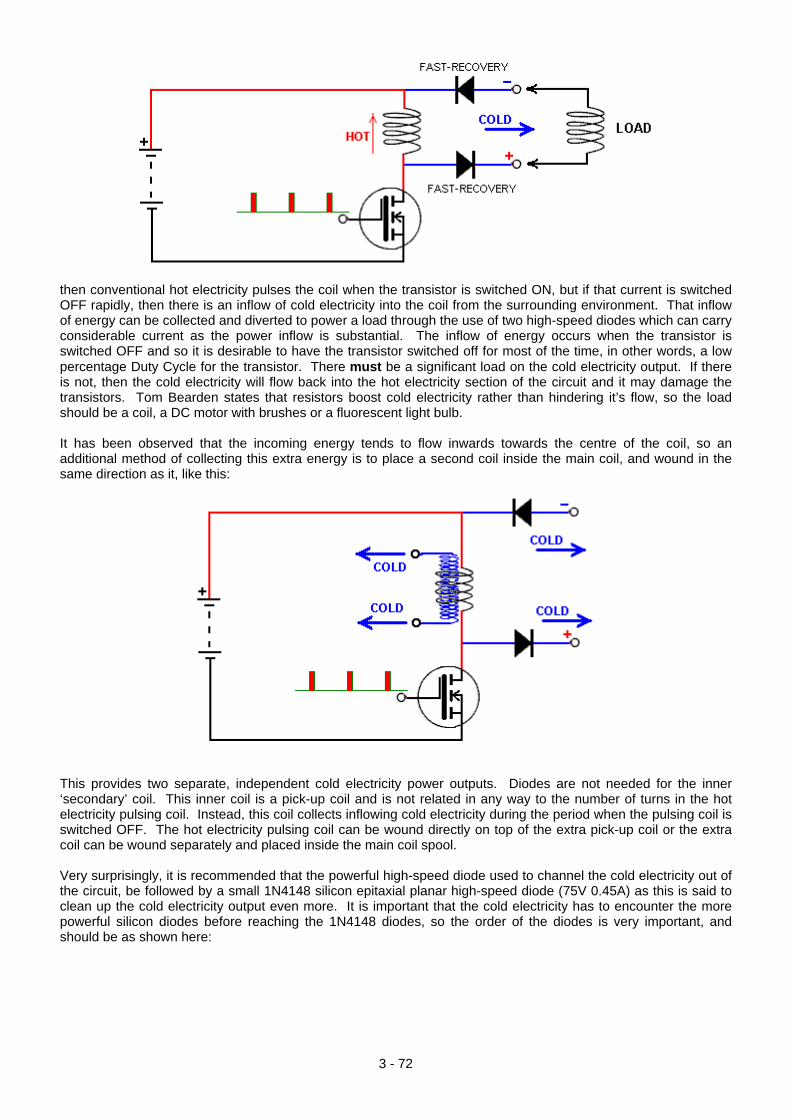
then conventional hot electricity pulses the coil when the transistor is switched ON, but if that current is switched OFF rapidly, then there is an inflow of cold electricity into the coil from the surrounding environment. That inflow of energy can be collected and diverted to power a load through the use of two high-speed diodes which can carry considerable current as the power inflow is substantial. The inflow of energy occurs when the transistor is switched OFF and so it is desirable to have the transistor switched off for most of the time, in other words, a low percentage Duty Cycle for the transistor. There must be a significant load on the cold electricity output. If there is not, then the cold electricity will flow back into the hot electricity section of the circuit and it may damage the transistors. Tom Bearden states that resistors boost cold electricity rather than hindering it’s flow, so the load should be a coil, a DC motor with brushes or a fluorescent light bulb. It has been observed that the incoming energy tends to flow inwards towards the centre of the coil, so an additional method of collecting this extra energy is to place a second coil inside the main coil, and wound in the same direction as it, like this:
This provides two separate, independent cold electricity power outputs. Diodes are not needed for the inner ‘secondary’ coil. This inner coil is a pick-up coil and is not related in any way to the number of turns in the hot electricity pulsing coil. Instead, this coil collects inflowing cold electricity during the period when the pulsing coil is switched OFF. The hot electricity pulsing coil can be wound directly on top of the extra pick-up coil or the extra coil can be wound separately and placed inside the main coil spool. Very surprisingly, it is recommended that the powerful high-speed diode used to channel the cold electricity out of the circuit, be followed by a small 1N4148 silicon epitaxial planar high-speed diode (75V 0.45A) as this is said to clean up the cold electricity output even more. It is important that the cold electricity has to encounter the more powerful silicon diodes before reaching the 1N4148 diodes, so the order of the diodes is very important, and should be as shown here:
3 - 72
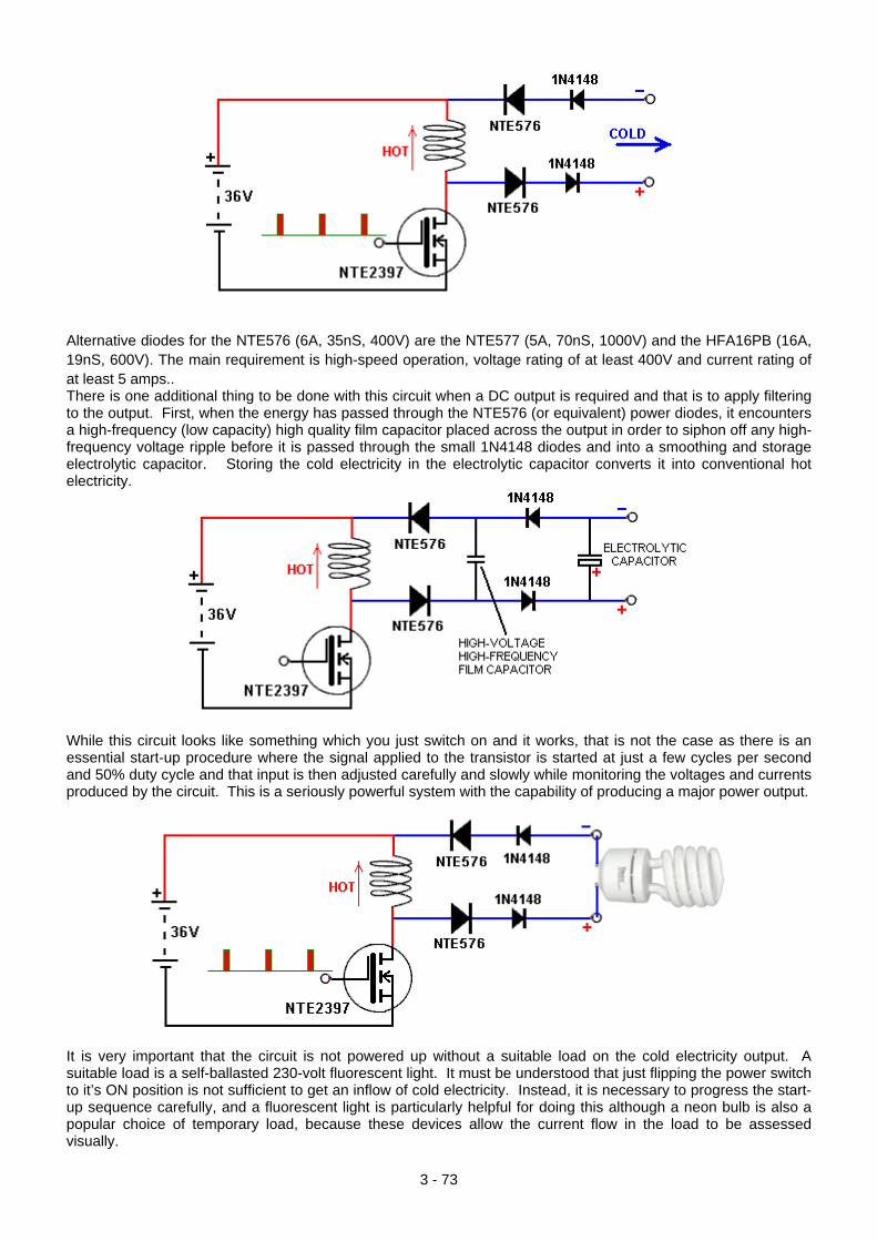
Alternative diodes for the NTE576 (6A, 35nS, 400V) are the NTE577 (5A, 70nS, 1000V) and the HFA16PB (16A, 19nS, 600V). The main requirement is high-speed operation, voltage rating of at least 400V and current rating of at least 5 amps.. There is one additional thing to be done with this circuit when a DC output is required and that is to apply filtering to the output. First, when the energy has passed through the NTE576 (or equivalent) power diodes, it encounters a high-frequency (low capacity) high quality film capacitor placed across the output in order to siphon off any high-frequency voltage ripple before it is passed through the small 1N4148 diodes and into a smoothing and storage electrolytic capacitor. Storing the cold electricity in the electrolytic capacitor converts it into conventional hot electricity.
While this circuit looks like something which you just switch on and it works, that is not the case as there is an essential start-up procedure where the signal applied to the transistor is started at just a few cycles per second and 50% duty cycle and that input is then adjusted carefully and slowly while monitoring the voltages and currents produced by the circuit. This is a seriously powerful system with the capability of producing a major power output.
It is very important that the circuit is not powered up without a suitable load on the cold electricity output. A suitable load is a self-ballasted 230-volt fluorescent light. It must be understood that just flipping the power switch to it’s ON position is not sufficient to get an inflow of cold electricity. Instead, it is necessary to progress the start-up sequence carefully, and a fluorescent light is particularly helpful for doing this although a neon bulb is also a popular choice of temporary load, because these devices allow the current flow in the load to be assessed visually.
3 - 73
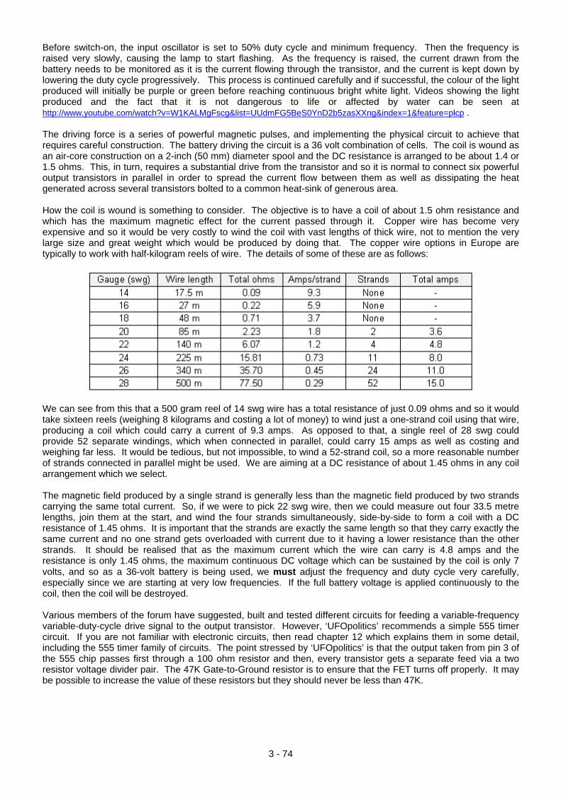
Before switch-on, the input oscillator is set to 50% duty cycle and minimum frequency. Then the frequency is raised very slowly, causing the lamp to start flashing. As the frequency is raised, the current drawn from the battery needs to be monitored as it is the current flowing through the transistor, and the current is kept down by lowering the duty cycle progressively. This process is continued carefully and if successful, the colour of the light produced will initially be purple or green before reaching continuous bright white light. Videos showing the light produced and the fact that it is not dangerous to life or affected by water can be seen at http://www.youtube.com/watch?v=W1KALMgFscg&list=UUdmFG5BeS0YnD2b5zasXXng&index=1&feature=plcp . The driving force is a series of powerful magnetic pulses, and implementing the physical circuit to achieve that requires careful construction. The battery driving the circuit is a 36 volt combination of cells. The coil is wound as an air-core construction on a 2-inch (50 mm) diameter spool and the DC resistance is arranged to be about 1.4 or 1.5 ohms. This, in turn, requires a substantial drive from the transistor and so it is normal to connect six powerful output transistors in parallel in order to spread the current flow between them as well as dissipating the heat generated across several transistors bolted to a common heat-sink of generous area. How the coil is wound is something to consider. The objective is to have a coil of about 1.5 ohm resistance and which has the maximum magnetic effect for the current passed through it. Copper wire has become very expensive and so it would be very costly to wind the coil with vast lengths of thick wire, not to mention the very large size and great weight which would be produced by doing that. The copper wire options in Europe are typically to work with half-kilogram reels of wire. The details of some of these are as follows:
We can see from this that a 500 gram reel of 14 swg wire has a total resistance of just 0.09 ohms and so it would take sixteen reels (weighing 8 kilograms and costing a lot of money) to wind just a one-strand coil using that wire, producing a coil which could carry a current of 9.3 amps. As opposed to that, a single reel of 28 swg could provide 52 separate windings, which when connected in parallel, could carry 15 amps as well as costing and weighing far less. It would be tedious, but not impossible, to wind a 52-strand coil, so a more reasonable number of strands connected in parallel might be used. We are aiming at a DC resistance of about 1.45 ohms in any coil arrangement which we select. The magnetic field produced by a single strand is generally less than the magnetic field produced by two strands carrying the same total current. So, if we were to pick 22 swg wire, then we could measure out four 33.5 metre lengths, join them at the start, and wind the four strands simultaneously, side-by-side to form a coil with a DC resistance of 1.45 ohms. It is important that the strands are exactly the same length so that they carry exactly the same current and no one strand gets overloaded with current due to it having a lower resistance than the other strands. It should be realised that as the maximum current which the wire can carry is 4.8 amps and the resistance is only 1.45 ohms, the maximum continuous DC voltage which can be sustained by the coil is only 7 volts, and so as a 36-volt battery is being used, we must adjust the frequency and duty cycle very carefully, especially since we are starting at very low frequencies. If the full battery voltage is applied continuously to the coil, then the coil will be destroyed. Various members of the forum have suggested, built and tested different circuits for feeding a variable-frequency variable-duty-cycle drive signal to the output transistor. However, ‘UFOpolitics’ recommends a simple 555 timer circuit. If you are not familiar with electronic circuits, then read chapter 12 which explains them in some detail, including the 555 timer family of circuits. The point stressed by ‘UFOpolitics’ is that the output taken from pin 3 of the 555 chip passes first through a 100 ohm resistor and then, every transistor gets a separate feed via a two resistor voltage divider pair. The 47K Gate-to-Ground resistor is to ensure that the FET turns off properly. It may be possible to increase the value of these resistors but they should never be less than 47K.
3 - 74
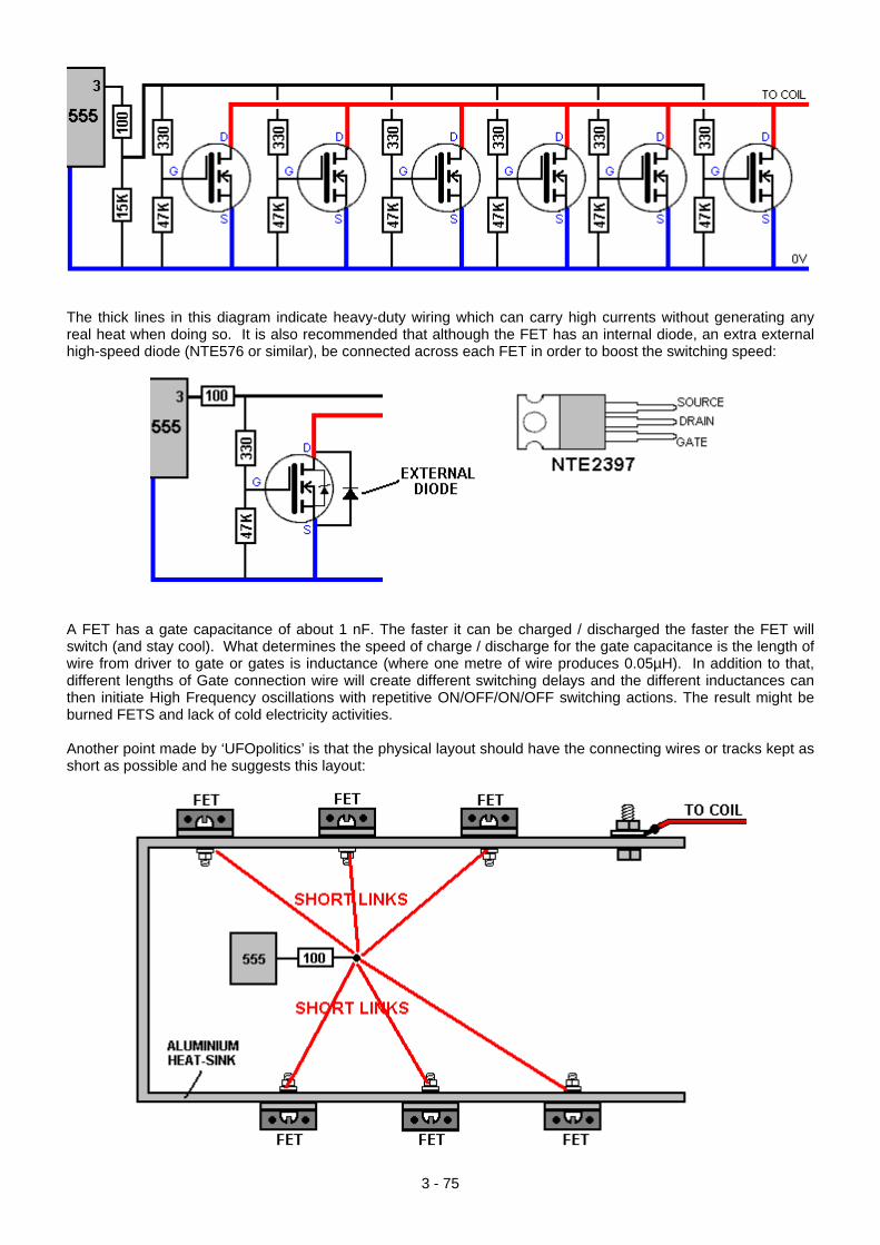
The thick lines in this diagram indicate heavy-duty wiring which can carry high currents without generating any real heat when doing so. It is also recommended that although the FET has an internal diode, an extra external high-speed diode (NTE576 or similar), be connected across each FET in order to boost the switching speed:
A FET has a gate capacitance of about 1 nF. The faster it can be charged / discharged the faster the FET will switch (and stay cool). What determines the speed of charge / discharge for the gate capacitance is the length of wire from driver to gate or gates is inductance (where one metre of wire produces 0.05µH). In addition to that, different lengths of Gate connection wire will create different switching delays and the different inductances can then initiate High Frequency oscillations with repetitive ON/OFF/ON/OFF switching actions. The result might be burned FETS and lack of cold electricity activities. Another point made by ‘UFOpolitics’ is that the physical layout should have the connecting wires or tracks kept as short as possible and he suggests this layout:
3 - 75
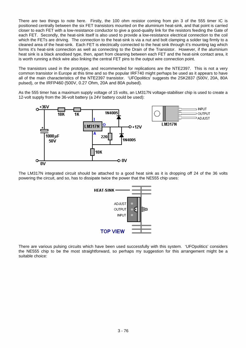
There are two things to note here. Firstly, the 100 ohm resistor coming from pin 3 of the 555 timer IC is positioned centrally between the six FET transistors mounted on the aluminium heat-sink, and that point is carried closer to each FET with a low-resistance conductor to give a good-quality link for the resistors feeding the Gate of each FET. Secondly, the heat-sink itself is also used to provide a low-resistance electrical connection to the coil which the FETs are driving. The connection to the heat-sink is via a nut and bolt clamping a solder tag firmly to a cleaned area of the heat-sink. Each FET is electrically connected to the heat sink through it’s mounting tag which forms it’s heat-sink connection as well as connecting to the Drain of the Transistor. However, if the aluminium heat sink is a black anodised type, then, apart from cleaning between each FET and the heat-sink contact area, it is worth running a thick wire also linking the central FET pins to the output wire connection point. The transistors used in the prototype, and recommended for replications are the NTE2397. This is not a very common transistor in Europe at this time and so the popular IRF740 might perhaps be used as it appears to have all of the main characteristics of the NTE2397 transistor. ‘UFOpolitics’ suggests the 2SK2837 (500V, 20A, 80A pulsed), or the IRFP460 (500V, 0.27 Ohm, 20A and 80A pulsed). As the 555 timer has a maximum supply voltage of 15 volts, an LM317N voltage-stabiliser chip is used to create a 12-volt supply from the 36-volt battery (a 24V battery could be used):
The LM317N integrated circuit should be attached to a good heat sink as it is dropping off 24 of the 36 volts powering the circuit, and so, has to dissipate twice the power that the NE555 chip uses:
There are various pulsing circuits which have been used successfully with this system. ‘UFOpolitics’ considers the NE555 chip to be the most straightforward, so perhaps my suggestion for this arrangement might be a suitable choice:
3 - 76
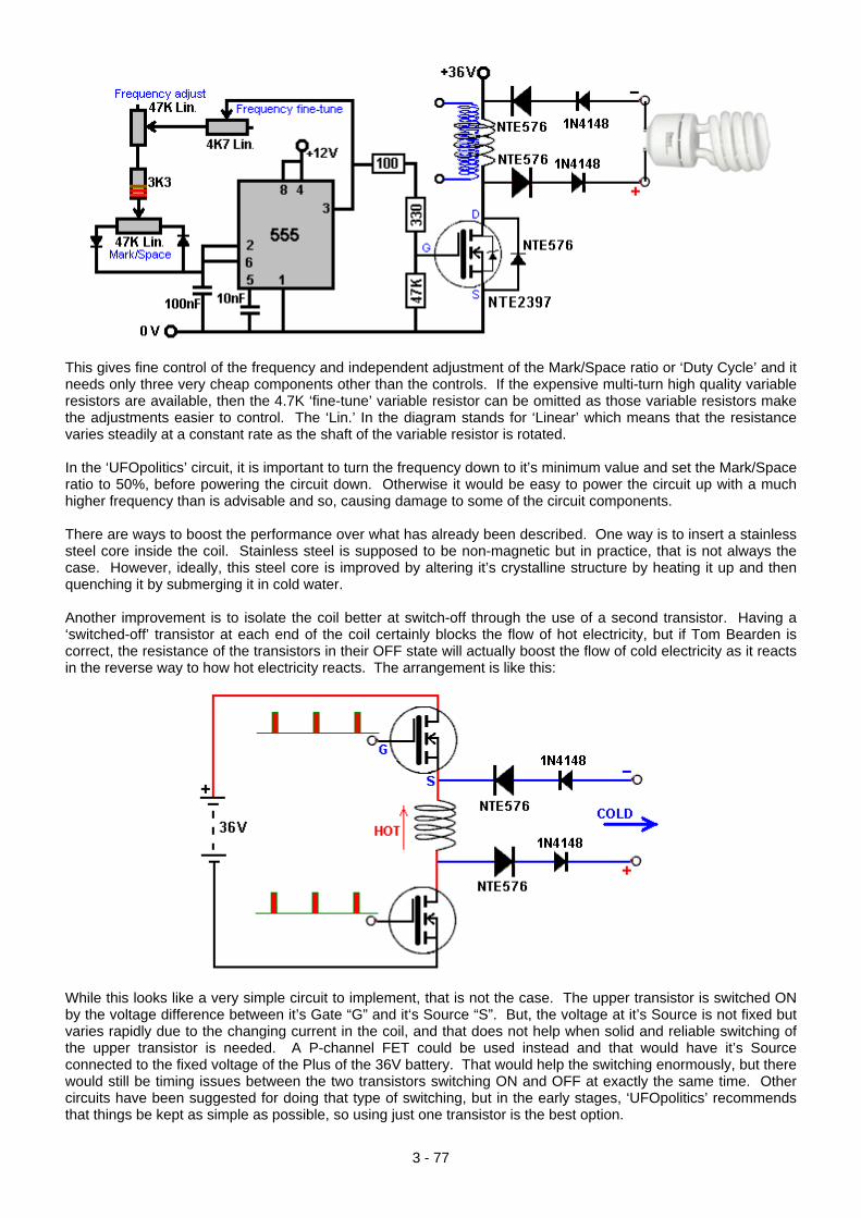
This gives fine control of the frequency and independent adjustment of the Mark/Space ratio or ‘Duty Cycle’ and it needs only three very cheap components other than the controls. If the expensive multi-turn high quality variable resistors are available, then the 4.7K ‘fine-tune’ variable resistor can be omitted as those variable resistors make the adjustments easier to control. The ‘Lin.’ In the diagram stands for ‘Linear’ which means that the resistance varies steadily at a constant rate as the shaft of the variable resistor is rotated. In the ‘UFOpolitics’ circuit, it is important to turn the frequency down to it’s minimum value and set the Mark/Space ratio to 50%, before powering the circuit down. Otherwise it would be easy to power the circuit up with a much higher frequency than is advisable and so, causing damage to some of the circuit components. There are ways to boost the performance over what has already been described. One way is to insert a stainless steel core inside the coil. Stainless steel is supposed to be non-magnetic but in practice, that is not always the case. However, ideally, this steel core is improved by altering it’s crystalline structure by heating it up and then quenching it by submerging it in cold water. Another improvement is to isolate the coil better at switch-off through the use of a second transistor. Having a ‘switched-off’ transistor at each end of the coil certainly blocks the flow of hot electricity, but if Tom Bearden is correct, the resistance of the transistors in their OFF state will actually boost the flow of cold electricity as it reacts in the reverse way to how hot electricity reacts. The arrangement is like this:
While this looks like a very simple circuit to implement, that is not the case. The upper transistor is switched ON by the voltage difference between it’s Gate “G” and it‘s Source “S”. But, the voltage at it’s Source is not fixed but varies rapidly due to the changing current in the coil, and that does not help when solid and reliable switching of the upper transistor is needed. A P-channel FET could be used instead and that would have it’s Source connected to the fixed voltage of the Plus of the 36V battery. That would help the switching enormously, but there would still be timing issues between the two transistors switching ON and OFF at exactly the same time. Other circuits have been suggested for doing that type of switching, but in the early stages, ‘UFOpolitics’ recommends that things be kept as simple as possible, so using just one transistor is the best option.
3 - 77
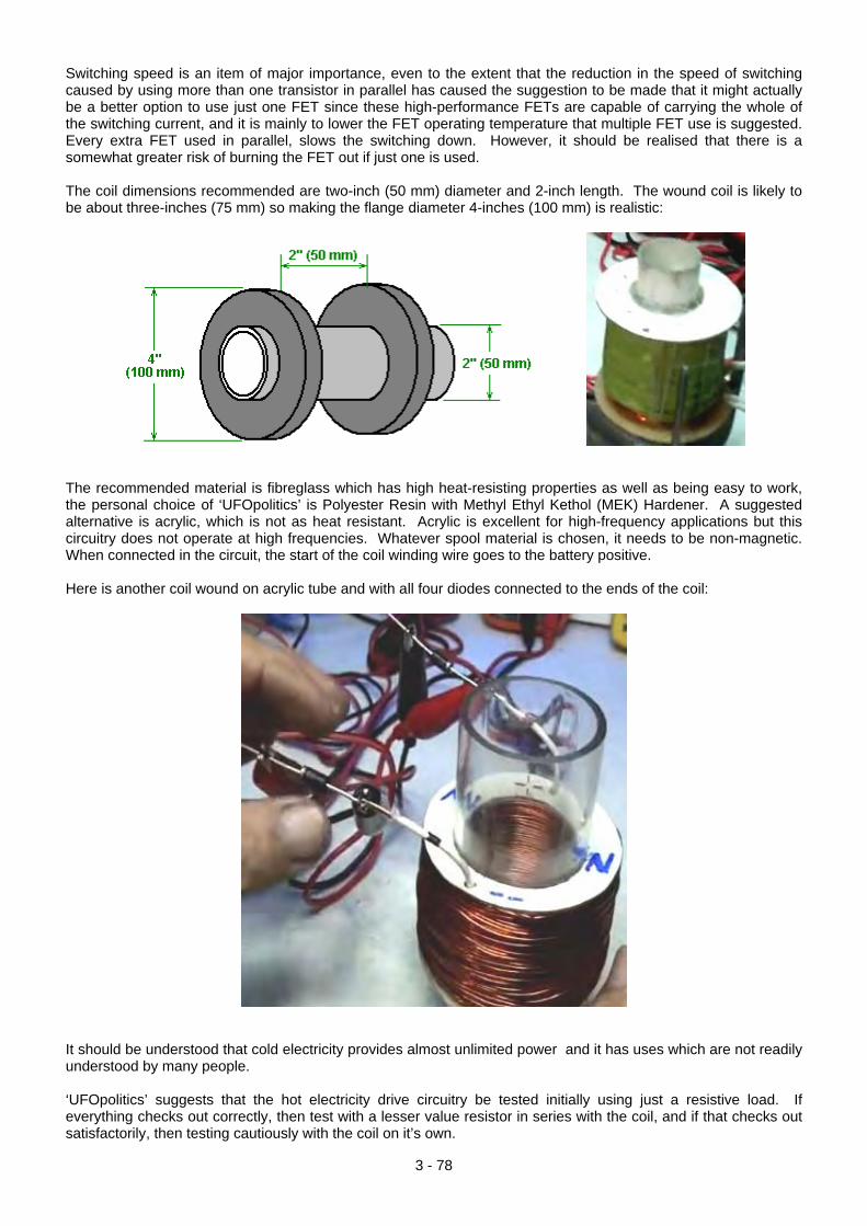
Switching speed is an item of major importance, even to the extent that the reduction in the speed of switching caused by using more than one transistor in parallel has caused the suggestion to be made that it might actually be a better option to use just one FET since these high-performance FETs are capable of carrying the whole of the switching current, and it is mainly to lower the FET operating temperature that multiple FET use is suggested. Every extra FET used in parallel, slows the switching down. However, it should be realised that there is a somewhat greater risk of burning the FET out if just one is used. The coil dimensions recommended are two-inch (50 mm) diameter and 2-inch length. The wound coil is likely to be about three-inches (75 mm) so making the flange diameter 4-inches (100 mm) is realistic:
The recommended material is fibreglass which has high heat-resisting properties as well as being easy to work, the personal choice of ‘UFOpolitics’ is Polyester Resin with Methyl Ethyl Kethol (MEK) Hardener. A suggested alternative is acrylic, which is not as heat resistant. Acrylic is excellent for high-frequency applications but this circuitry does not operate at high frequencies. Whatever spool material is chosen, it needs to be non-magnetic. When connected in the circuit, the start of the coil winding wire goes to the battery positive. Here is another coil wound on acrylic tube and with all four diodes connected to the ends of the coil:
It should be understood that cold electricity provides almost unlimited power and it has uses which are not readily understood by many people. ‘UFOpolitics’ suggests that the hot electricity drive circuitry be tested initially using just a resistive load. If everything checks out correctly, then test with a lesser value resistor in series with the coil, and if that checks out satisfactorily, then testing cautiously with the coil on it’s own.
3 - 78
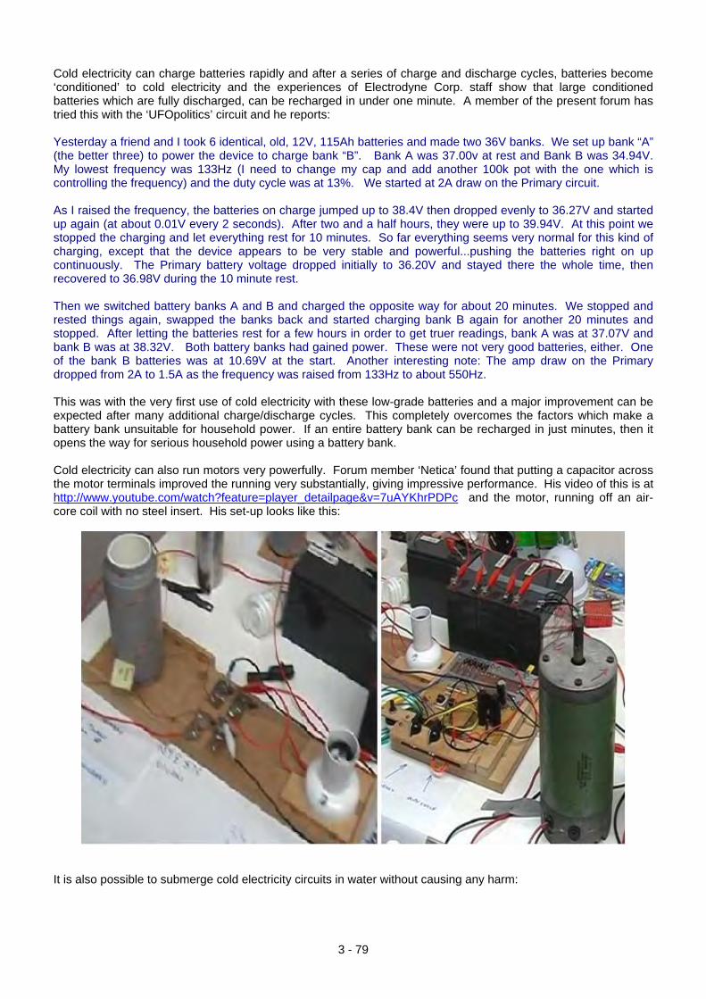
Cold electricity can charge batteries rapidly and after a series of charge and discharge cycles, batteries become ‘conditioned’ to cold electricity and the experiences of Electrodyne Corp. staff show that large conditioned batteries which are fully discharged, can be recharged in under one minute. A member of the present forum has tried this with the ‘UFOpolitics’ circuit and he reports: Yesterday a friend and I took 6 identical, old, 12V, 115Ah batteries and made two 36V banks. We set up bank “A” (the better three) to power the device to charge bank “B”. Bank A was 37.00v at rest and Bank B was 34.94V. My lowest frequency was 133Hz (I need to change my cap and add another 100k pot with the one which is controlling the frequency) and the duty cycle was at 13%. We started at 2A draw on the Primary circuit. As I raised the frequency, the batteries on charge jumped up to 38.4V then dropped evenly to 36.27V and started up again (at about 0.01V every 2 seconds). After two and a half hours, they were up to 39.94V. At this point we stopped the charging and let everything rest for 10 minutes. So far everything seems very normal for this kind of charging, except that the device appears to be very stable and powerful...pushing the batteries right on up continuously. The Primary battery voltage dropped initially to 36.20V and stayed there the whole time, then recovered to 36.98V during the 10 minute rest. Then we switched battery banks A and B and charged the opposite way for about 20 minutes. We stopped and rested things again, swapped the banks back and started charging bank B again for another 20 minutes and stopped. After letting the batteries rest for a few hours in order to get truer readings, bank A was at 37.07V and bank B was at 38.32V. Both battery banks had gained power. These were not very good batteries, either. One of the bank B batteries was at 10.69V at the start. Another interesting note: The amp draw on the Primary dropped from 2A to 1.5A as the frequency was raised from 133Hz to about 550Hz. This was with the very first use of cold electricity with these low-grade batteries and a major improvement can be expected after many additional charge/discharge cycles. This completely overcomes the factors which make a battery bank unsuitable for household power. If an entire battery bank can be recharged in just minutes, then it opens the way for serious household power using a battery bank. Cold electricity can also run motors very powerfully. Forum member ‘Netica’ found that putting a capacitor across the motor terminals improved the running very substantially, giving impressive performance. His video of this is at http://www.youtube.com/watch?feature=player_detailpage&v=7uAYKhrPDPc and the motor, running off an air-core coil with no steel insert. His set-up looks like this:
It is also possible to submerge cold electricity circuits in water without causing any harm:
3 - 79
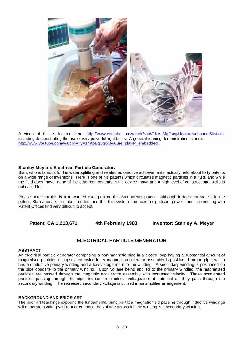
A video of this is located here: http://www.youtube.com/watch?v=W1KALMgFscg&feature=channel&list=UL including demonstrating the use of very powerful light bulbs. A general running demonstration is here: http://www.youtube.com/watch?v=yVzhKpEqUgc&feature=player_embedded . Stanley Meyer’s Electrical Particle Generator. Stan, who is famous for his water-splitting and related automotive achievements, actually held about forty patents on a wide range of inventions. Here is one of his patents which circulates magnetic particles in a fluid, and while the fluid does move, none of the other components in the device move and a high level of constructional skills is not called for: Please note that this is a re-worded excerpt from this Stan Meyer patent. Although it does not state it in the patent, Stan appears to make it understood that this system produces a significant power gain – something with Patent Offices find very difficult to accept.
Patent CA 1,213,671 4th February 1983 Inventor: Stanley A. Meyer
ELECTRICAL PARTICLE GENERATOR ABSTRACT An electrical particle generator comprising a non-magnetic pipe in a closed loop having a substantial amount of magnetised particles encapsulated inside it. A magnetic accelerator assembly is positioned on the pipe, which has an inductive primary winding and a low-voltage input to the winding. A secondary winding is positioned on the pipe opposite to the primary winding. Upon voltage being applied to the primary winding, the magnetised particles are passed through the magnetic accelerator assembly with increased velocity. These accelerated particles passing through the pipe, induce an electrical voltage/current potential as they pass through the secondary winding. The increased secondary voltage is utilised in an amplifier arrangement. BACKGROUND AND PRIOR ART The prior art teachings expound the fundamental principle tat a magnetic field passing through inductive windings will generate a voltage/current or enhance the voltage across it if the winding is a secondary winding.
3 - 80
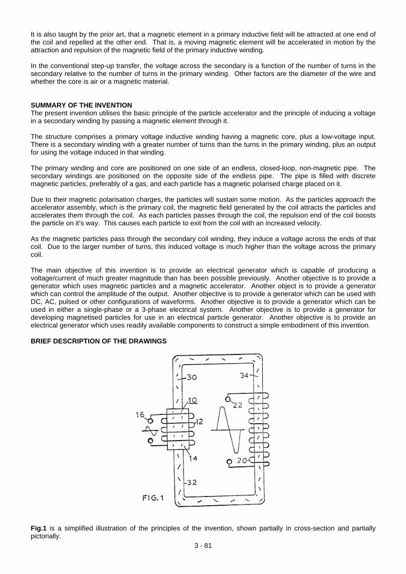
It is also taught by the prior art, that a magnetic element in a primary inductive field will be attracted at one end of the coil and repelled at the other end. That is, a moving magnetic element will be accelerated in motion by the attraction and repulsion of the magnetic field of the primary inductive winding. In the conventional step-up transfer, the voltage across the secondary is a function of the number of turns in the secondary relative to the number of turns in the primary winding. Other factors are the diameter of the wire and whether the core is air or a magnetic material. SUMMARY OF THE INVENTION The present invention utilises the basic principle of the particle accelerator and the principle of inducing a voltage in a secondary winding by passing a magnetic element through it. The structure comprises a primary voltage inductive winding having a magnetic core, plus a low-voltage input. There is a secondary winding with a greater number of turns than the turns in the primary winding, plus an output for using the voltage induced in that winding. The primary winding and core are positioned on one side of an endless, closed-loop, non-magnetic pipe. The secondary windings are positioned on the opposite side of the endless pipe. The pipe is filled with discrete magnetic particles, preferably of a gas, and each particle has a magnetic polarised charge placed on it. Due to their magnetic polarisation charges, the particles will sustain some motion. As the particles approach the accelerator assembly, which is the primary coil, the magnetic field generated by the coil attracts the particles and accelerates them through the coil. As each particles passes through the coil, the repulsion end of the coil boosts the particle on it’s way. This causes each particle to exit from the coil with an increased velocity. As the magnetic particles pass through the secondary coil winding, they induce a voltage across the ends of that coil. Due to the larger number of turns, this induced voltage is much higher than the voltage across the primary coil. The main objective of this invention is to provide an electrical generator which is capable of producing a voltage/current of much greater magnitude than has been possible previously. Another objective is to provide a generator which uses magnetic particles and a magnetic accelerator. Another object is to provide a generator which can control the amplitude of the output. Another objective is to provide a generator which can be used with DC, AC, pulsed or other configurations of waveforms. Another objective is to provide a generator which can be used in either a single-phase or a 3-phase electrical system. Another objective is to provide a generator for developing magnetised particles for use in an electrical particle generator. Another objective is to provide an electrical generator which uses readily available components to construct a simple embodiment of this invention. BRIEF DESCRIPTION OF THE DRAWINGS
Fig.1 is a simplified illustration of the principles of the invention, shown partially in cross-section and partially pictorially.
3 - 81
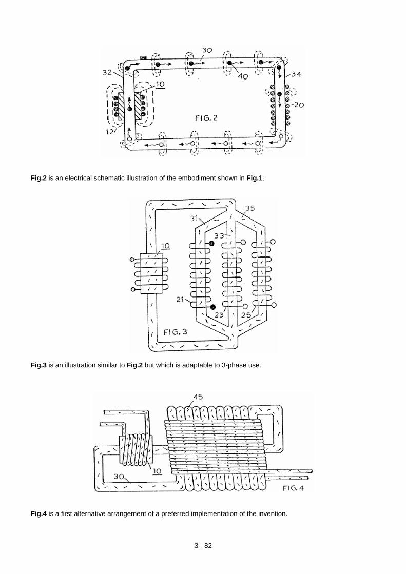
Fig.2 is an electrical schematic illustration of the embodiment shown in Fig.1.
Fig.3 is an illustration similar to Fig.2 but which is adaptable to 3-phase use.
Fig.4 is a first alternative arrangement of a preferred implementation of the invention.
3 - 82
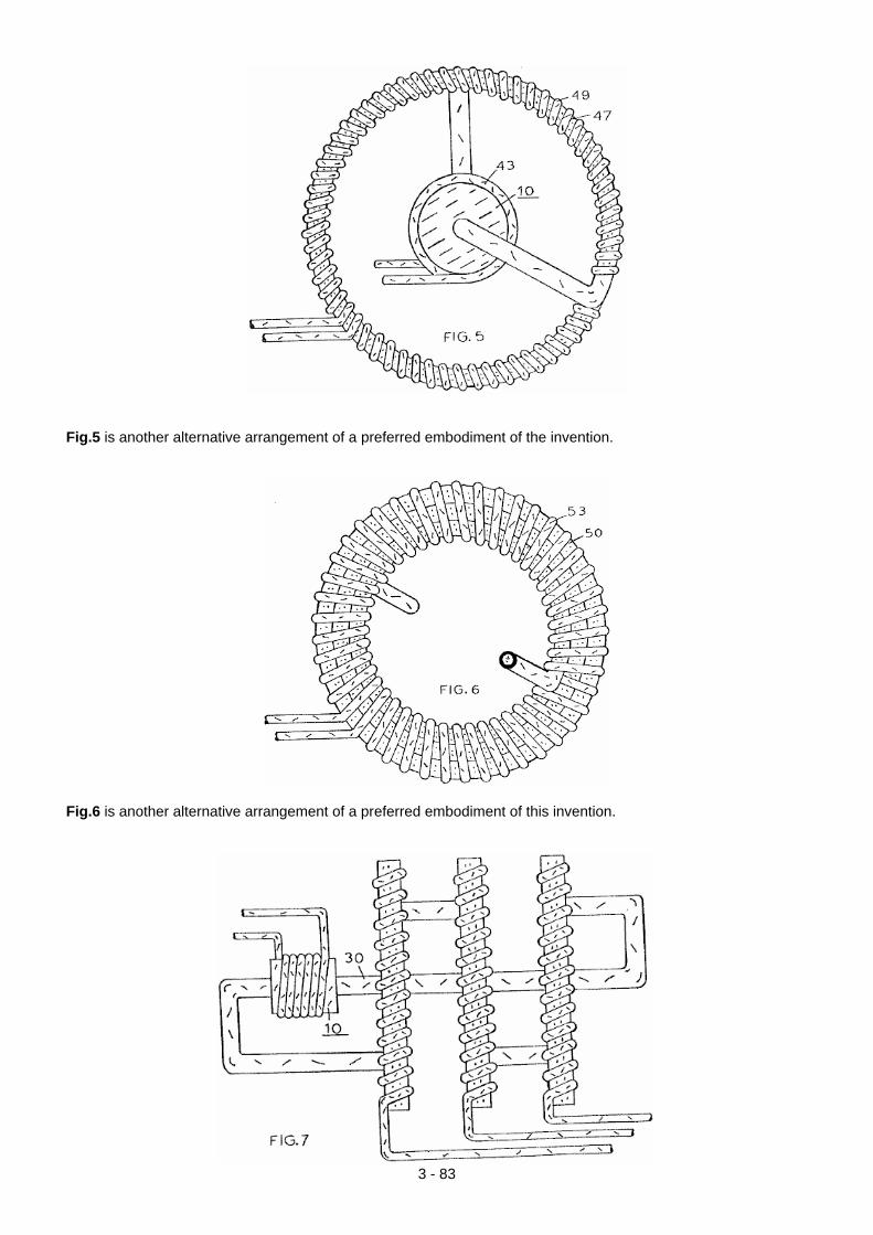
Fig.5 is another alternative arrangement of a preferred embodiment of the invention.
Fig.6 is another alternative arrangement of a preferred embodiment of this invention.
3 - 83
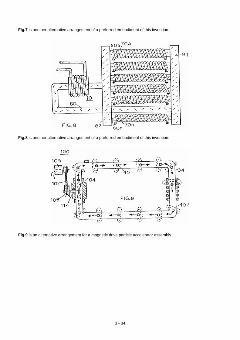
Fig.7 is another alternative arrangement of a preferred embodiment of this invention.
Fig.8 is another alternative arrangement of a preferred embodiment of this invention.
Fig.9 is an alternative arrangement for a magnetic drive particle accelerator assembly.
3 - 84
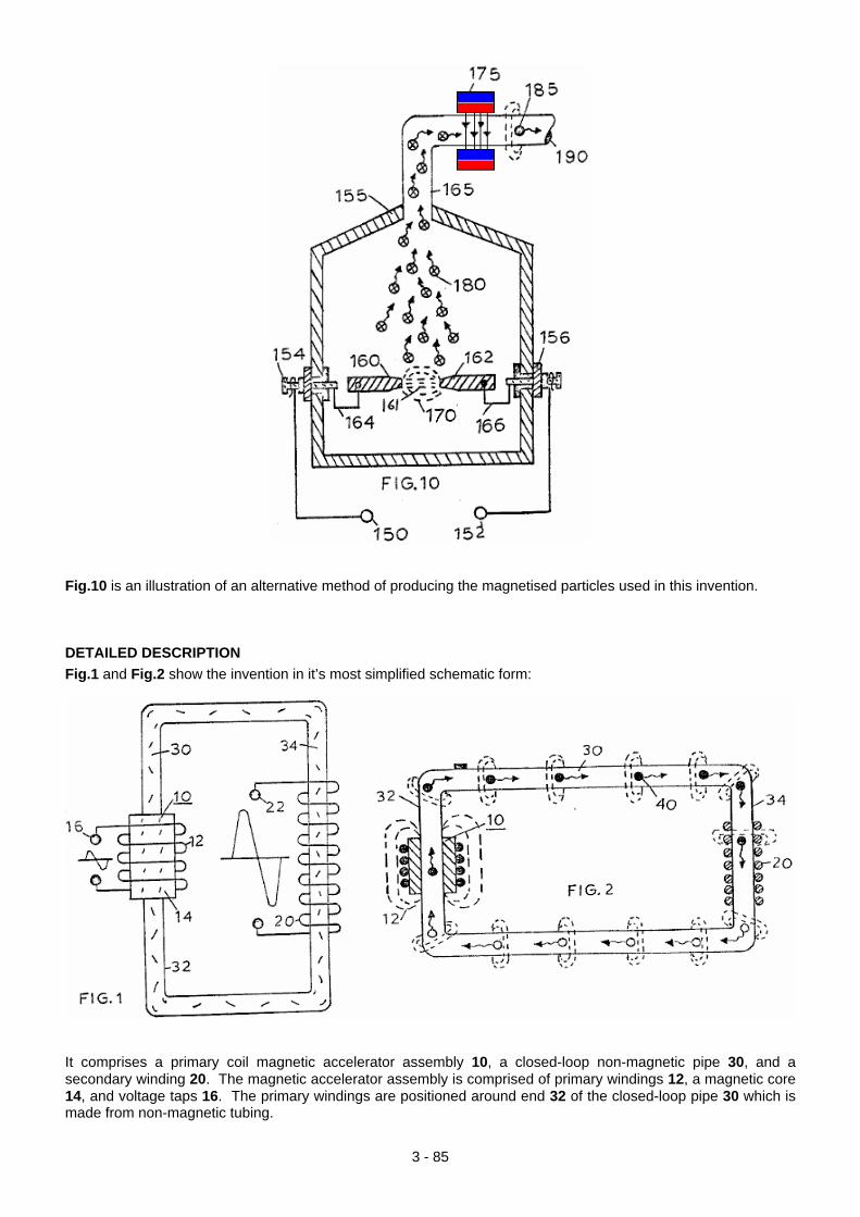
Fig.10 is an illustration of an alternative method of producing the magnetised particles used in this invention. DETAILED DESCRIPTION Fig.1 and Fig.2 show the invention in it’s most simplified schematic form:
It comprises a primary coil magnetic accelerator assembly 10, a closed-loop non-magnetic pipe 30, and a secondary winding 20. The magnetic accelerator assembly is comprised of primary windings 12, a magnetic core 14, and voltage taps 16. The primary windings are positioned around end 32 of the closed-loop pipe 30 which is made from non-magnetic tubing.
3 - 85
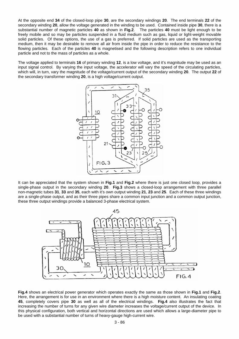
At the opposite end 34 of the closed-loop pipe 30, are the secondary windings 20. The end terminals 22 of the secondary winding 20, allow the voltage generated in the winding to be used. Contained inside pipe 30, there is a substantial number of magnetic particles 40 as shown in Fig.2. The particles 40 must be light enough to be freely mobile and so may be particles suspended in a fluid medium such as gas, liquid or light-weight movable solid particles. Of these options, the use of a gas is preferred. If solid particles are used as the transporting medium, then it may be desirable to remove all air from inside the pipe in order to reduce the resistance to the flowing particles. Each of the particles 40 is magnetised and the following description refers to one individual particle and not to the mass of particles as a whole. The voltage applied to terminals 16 of primary winding 12, is a low voltage, and it’s magnitude may be used as an input signal control. By varying the input voltage, the accelerator will vary the speed of the circulating particles, which will, in turn, vary the magnitude of the voltage/current output of the secondary winding 20. The output 22 of the secondary transformer winding 20, is a high voltage/current output.
It can be appreciated that the system shown in Fig.1 and Fig.2 where there is just one closed loop, provides a single-phase output in the secondary winding 20. Fig.3 shows a closed-loop arrangement with three parallel non-magnetic tubes 31, 33 and 35, each with it’s own output winding 21, 23 and 25. Each of these three windings are a single-phase output, and as their three pipes share a common input junction and a common output junction, these three output windings provide a balanced 3-phase electrical system.
Fig.4 shows an electrical power generator which operates exactly the same as those shown in Fig.1 and Fig.2. Here, the arrangement is for use in an environment where there is a high moisture content. An insulating coating 45, completely covers pipe 30 as well as all of the electrical windings. Fig.4 also illustrates the fact that increasing the number of turns for any given wire diameter increases the voltage/current output of the device. In this physical configuration, both vertical and horizontal directions are used which allows a large-diameter pipe to be used with a substantial number of turns of heavy-gauge high-current wire.
3 - 86
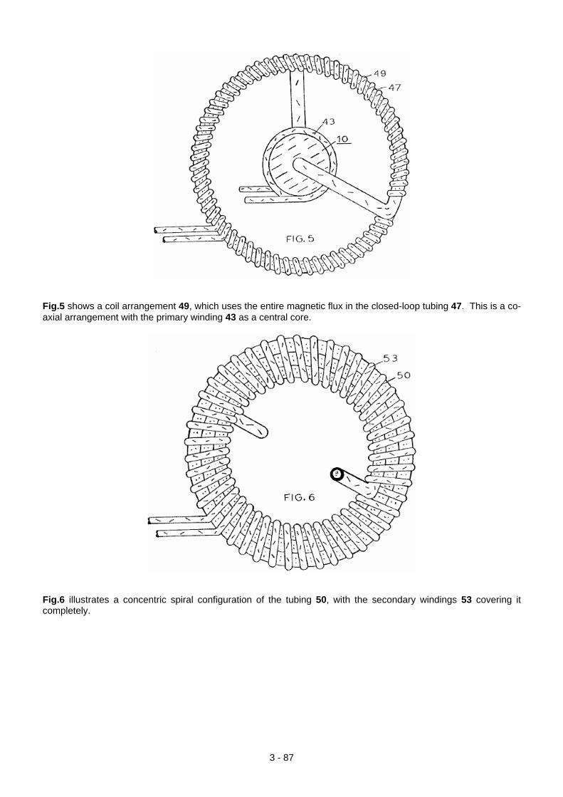
Fig.5 shows a coil arrangement 49, which uses the entire magnetic flux in the closed-loop tubing 47. This is a co-axial arrangement with the primary winding 43 as a central core.
Fig.6 illustrates a concentric spiral configuration of the tubing 50, with the secondary windings 53 covering it completely.
3 - 87
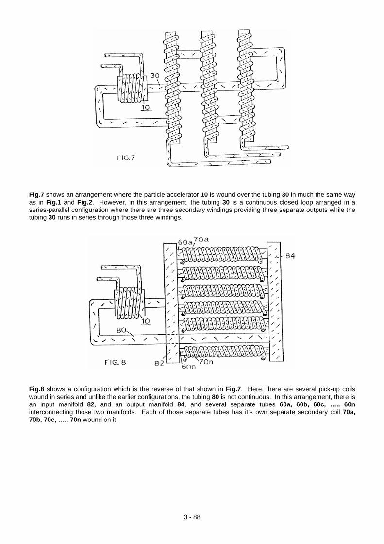
Fig.7 shows an arrangement where the particle accelerator 10 is wound over the tubing 30 in much the same way as in Fig.1 and Fig.2. However, in this arrangement, the tubing 30 is a continuous closed loop arranged in a series-parallel configuration where there are three secondary windings providing three separate outputs while the tubing 30 runs in series through those three windings.
Fig.8 shows a configuration which is the reverse of that shown in Fig.7. Here, there are several pick-up coils wound in series and unlike the earlier configurations, the tubing 80 is not continuous. In this arrangement, there is an input manifold 82, and an output manifold 84, and several separate tubes 60a, 60b, 60c, ….. 60n interconnecting those two manifolds. Each of those separate tubes has it’s own separate secondary coil 70a, 70b, 70c, ….. 70n wound on it.
3 - 88
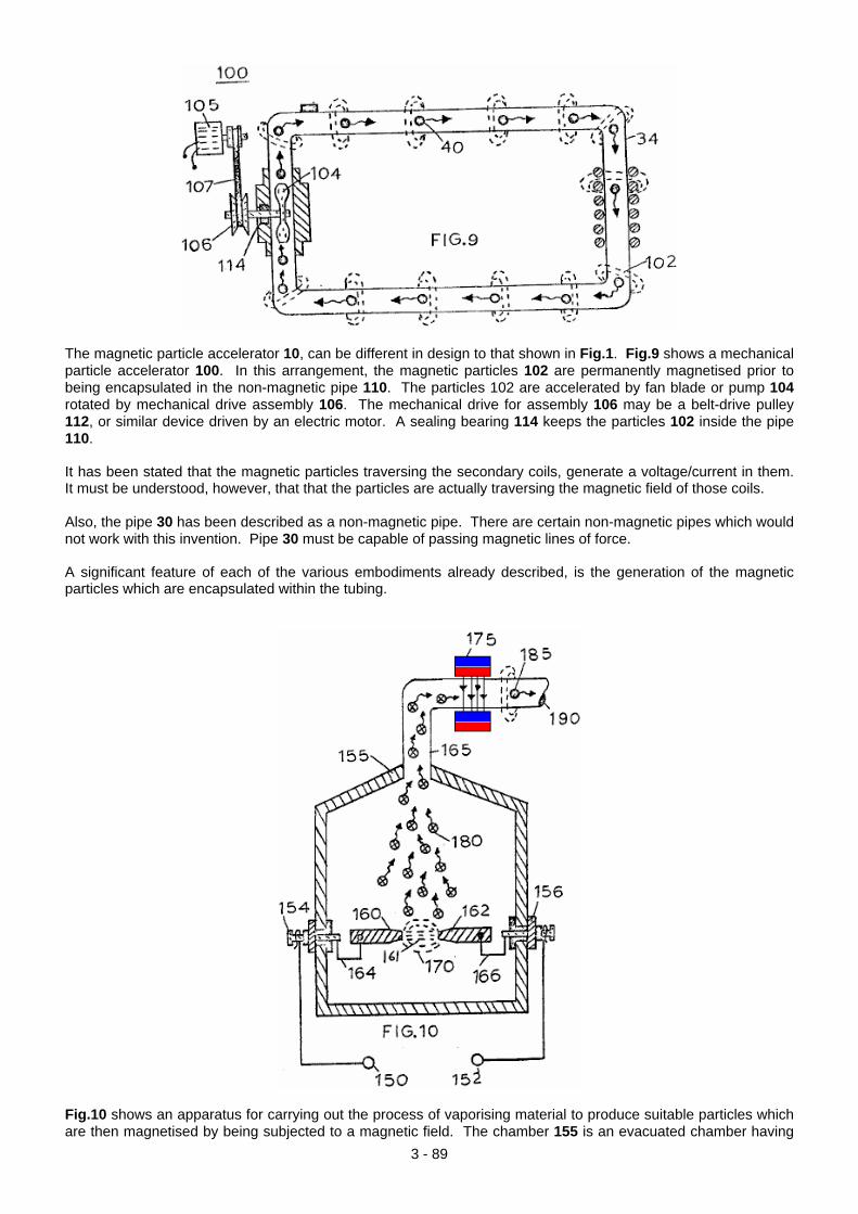
The magnetic particle accelerator 10, can be different in design to that shown in Fig.1. Fig.9 shows a mechanical particle accelerator 100. In this arrangement, the magnetic particles 102 are permanently magnetised prior to being encapsulated in the non-magnetic pipe 110. The particles 102 are accelerated by fan blade or pump 104 rotated by mechanical drive assembly 106. The mechanical drive for assembly 106 may be a belt-drive pulley 112, or similar device driven by an electric motor. A sealing bearing 114 keeps the particles 102 inside the pipe 110. It has been stated that the magnetic particles traversing the secondary coils, generate a voltage/current in them. It must be understood, however, that that the particles are actually traversing the magnetic field of those coils. Also, the pipe 30 has been described as a non-magnetic pipe. There are certain non-magnetic pipes which would not work with this invention. Pipe 30 must be capable of passing magnetic lines of force. A significant feature of each of the various embodiments already described, is the generation of the magnetic particles which are encapsulated within the tubing.
Fig.10 shows an apparatus for carrying out the process of vaporising material to produce suitable particles which are then magnetised by being subjected to a magnetic field. The chamber 155 is an evacuated chamber having
3 - 89
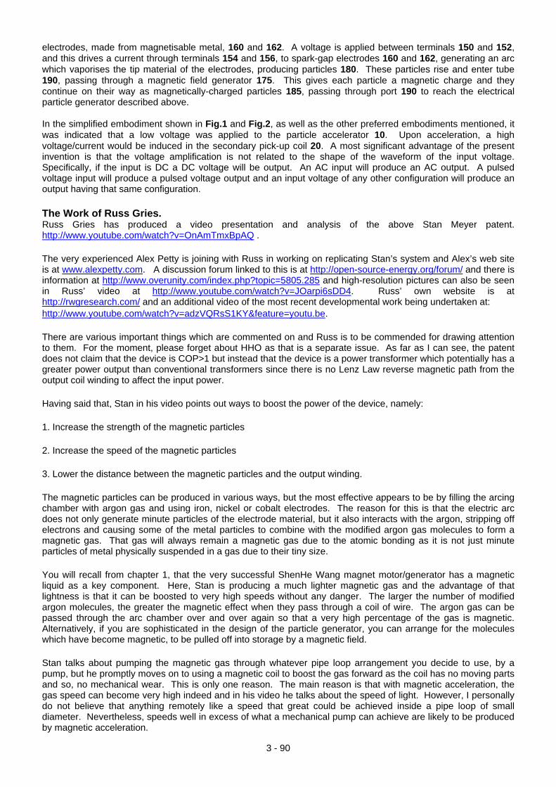
3 - 90
electrodes, made from magnetisable metal, 160 and 162. A voltage is applied between terminals 150 and 152, and this drives a current through terminals 154 and 156, to spark-gap electrodes 160 and 162, generating an arc which vaporises the tip material of the electrodes, producing particles 180. These particles rise and enter tube 190, passing through a magnetic field generator 175. This gives each particle a magnetic charge and they continue on their way as magnetically-charged particles 185, passing through port 190 to reach the electrical particle generator described above. In the simplified embodiment shown in Fig.1 and Fig.2, as well as the other preferred embodiments mentioned, it was indicated that a low voltage was applied to the particle accelerator 10. Upon acceleration, a high voltage/current would be induced in the secondary pick-up coil 20. A most significant advantage of the present invention is that the voltage amplification is not related to the shape of the waveform of the input voltage. Specifically, if the input is DC a DC voltage will be output. An AC input will produce an AC output. A pulsed voltage input will produce a pulsed voltage output and an input voltage of any other configuration will produce an output having that same configuration. The Work of Russ Gries. Russ Gries has produced a video presentation and analysis of the above Stan Meyer patent. http://www.youtube.com/watch?v=OnAmTmxBpAQ . The very experienced Alex Petty is joining with Russ in working on replicating Stan’s system and Alex’s web site is at www.alexpetty.com. A discussion forum linked to this is at http://open-source-energy.org/forum/ and there is information at http://www.overunity.com/index.php?topic=5805.285 and high-resolution pictures can also be seen in Russ’ video at http://www.youtube.com/watch?v=JOarpi6sDD4. Russ’ own website is at http://rwgresearch.com/ and an additional video of the most recent developmental work being undertaken at: http://www.youtube.com/watch?v=adzVQRsS1KY&feature=youtu.be. There are various important things which are commented on and Russ is to be commended for drawing attention to them. For the moment, please forget about HHO as that is a separate issue. As far as I can see, the patent does not claim that the device is COP>1 but instead that the device is a power transformer which potentially has a greater power output than conventional transformers since there is no Lenz Law reverse magnetic path from the output coil winding to affect the input power. Having said that, Stan in his video points out ways to boost the power of the device, namely: 1. Increase the strength of the magnetic particles 2. Increase the speed of the magnetic particles 3. Lower the distance between the magnetic particles and the output winding. The magnetic particles can be produced in various ways, but the most effective appears to be by filling the arcing chamber with argon gas and using iron, nickel or cobalt electrodes. The reason for this is that the electric arc does not only generate minute particles of the electrode material, but it also interacts with the argon, stripping off electrons and causing some of the metal particles to combine with the modified argon gas molecules to form a magnetic gas. That gas will always remain a magnetic gas due to the atomic bonding as it is not just minute particles of metal physically suspended in a gas due to their tiny size. You will recall from chapter 1, that the very successful ShenHe Wang magnet motor/generator has a magnetic liquid as a key component. Here, Stan is producing a much lighter magnetic gas and the advantage of that lightness is that it can be boosted to very high speeds without any danger. The larger the number of modified argon molecules, the greater the magnetic effect when they pass through a coil of wire. The argon gas can be passed through the arc chamber over and over again so that a very high percentage of the gas is magnetic. Alternatively, if you are sophisticated in the design of the particle generator, you can arrange for the molecules which have become magnetic, to be pulled off into storage by a magnetic field. Stan talks about pumping the magnetic gas through whatever pipe loop arrangement you decide to use, by a pump, but he promptly moves on to using a magnetic coil to boost the gas forward as the coil has no moving parts and so, no mechanical wear. This is only one reason. The main reason is that with magnetic acceleration, the gas speed can become very high indeed and in his video he talks about the speed of light. However, I personally do not believe that anything remotely like a speed that great could be achieved inside a pipe loop of small diameter. Nevertheless, speeds well in excess of what a mechanical pump can achieve are likely to be produced by magnetic acceleration.
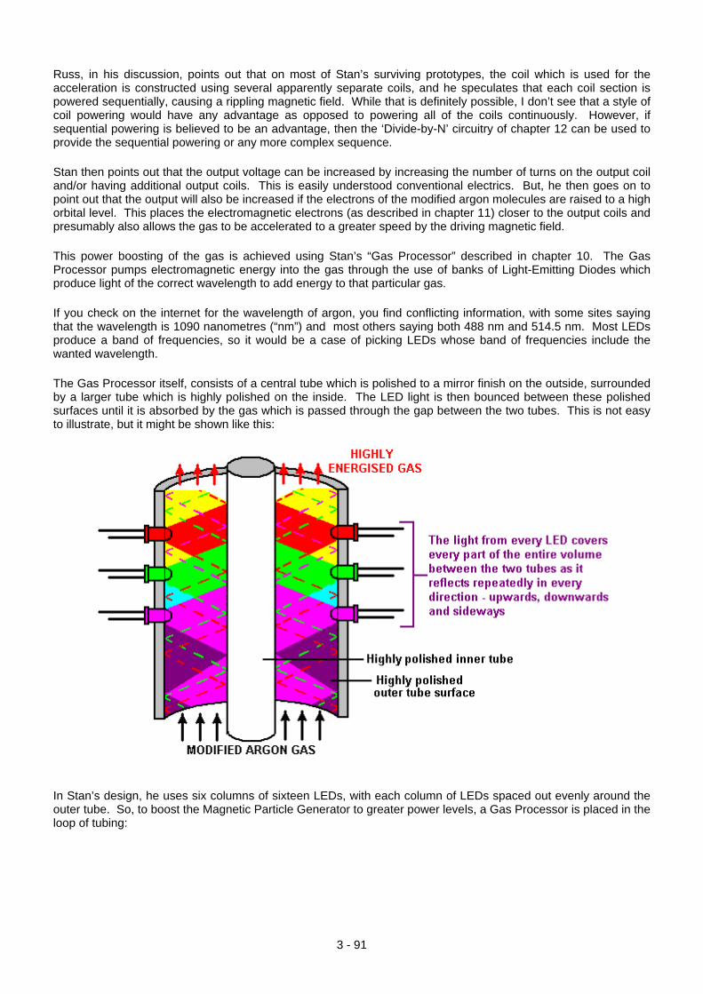
Russ, in his discussion, points out that on most of Stan’s surviving prototypes, the coil which is used for the acceleration is constructed using several apparently separate coils, and he speculates that each coil section is powered sequentially, causing a rippling magnetic field. While that is definitely possible, I don’t see that a style of coil powering would have any advantage as opposed to powering all of the coils continuously. However, if sequential powering is believed to be an advantage, then the ‘Divide-by-N’ circuitry of chapter 12 can be used to provide the sequential powering or any more complex sequence. Stan then points out that the output voltage can be increased by increasing the number of turns on the output coil and/or having additional output coils. This is easily understood conventional electrics. But, he then goes on to point out that the output will also be increased if the electrons of the modified argon molecules are raised to a high orbital level. This places the electromagnetic electrons (as described in chapter 11) closer to the output coils and presumably also allows the gas to be accelerated to a greater speed by the driving magnetic field. This power boosting of the gas is achieved using Stan’s “Gas Processor” described in chapter 10. The Gas Processor pumps electromagnetic energy into the gas through the use of banks of Light-Emitting Diodes which produce light of the correct wavelength to add energy to that particular gas. If you check on the internet for the wavelength of argon, you find conflicting information, with some sites saying that the wavelength is 1090 nanometres (“nm”) and most others saying both 488 nm and 514.5 nm. Most LEDs produce a band of frequencies, so it would be a case of picking LEDs whose band of frequencies include the wanted wavelength. The Gas Processor itself, consists of a central tube which is polished to a mirror finish on the outside, surrounded by a larger tube which is highly polished on the inside. The LED light is then bounced between these polished surfaces until it is absorbed by the gas which is passed through the gap between the two tubes. This is not easy to illustrate, but it might be shown like this:
In Stan’s design, he uses six columns of sixteen LEDs, with each column of LEDs spaced out evenly around the outer tube. So, to boost the Magnetic Particle Generator to greater power levels, a Gas Processor is placed in the loop of tubing:
3 - 91
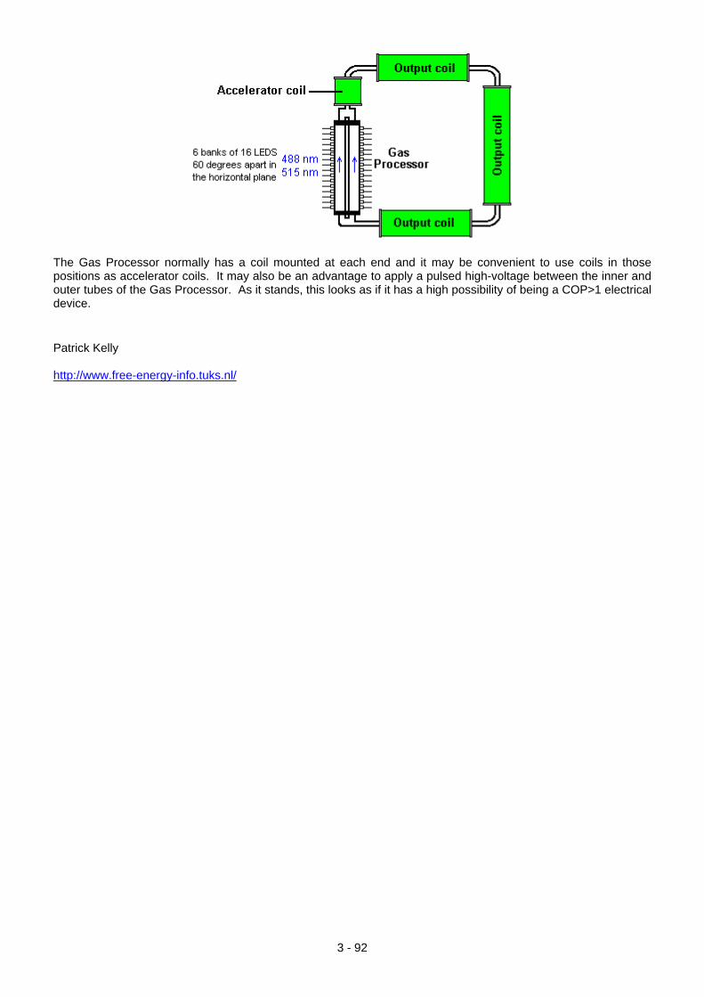
The Gas Processor normally has a coil mounted at each end and it may be convenient to use coils in those positions as accelerator coils. It may also be an advantage to apply a pulsed high-voltage between the inner and outer tubes of the Gas Processor. As it stands, this looks as if it has a high possibility of being a COP>1 electrical device. Patrick Kelly http://www.free-energy-info.tuks.nl/
3 - 92