Embed Size (px)
Citation preview

S U R F A C E W A T E R M A N A G E M E N T M A N U A L S E P T E M B E R 2 2 , 2 0 0 8 E D I T I O N
Chapter 3 Conveyance System Design and Hydraulic Analysis
This chapter presents acceptable methods for the analysis and design of storm and surface water conveyance systems. Conveyance systems can be separated into the following categories:
Pipe systems
Culverts
Open Channels (ditches, swales)
Outfalls
Pipe systems, culverts, and open channels are addressed in Section 3.4. Outfalls are addressed in Section 3.5.
The purpose of a conveyance system is to drain surface water, up to a specific design flow, from properties so as to provide protection to property and the environment. This chapter contains detailed design criteria, methods of analysis and standard details for all components of a conveyance system. A complete basic understanding of hydrology and hydraulics and the principles on which the methodology of hydrologic analysis is based is essential for the proper and accurate application of methods used in designing conveyance systems.
3.1 Conveyance System Analysis Requirements The project engineer shall provide calculations demonstrating the adequacy of all the project’s existing and proposed surface water conveyance system components. The project engineer shall provide calculations regarding all off-site flows as required by Volume 1. All relevant work/calculations shall be submitted for City review as part of a permit submittal.
3.1.1 On-site Analysis
All proposed on-site surface water conveyance systems shall be sized to meet the required design event per Section 3.2 below.
3.1.2 Offsite Analysis (1/4 mile Downstream Analysis)
Refer to Minimum Requirement #11 (Offsite Analysis and Mitigation) in Volume 1 to determine whether a downstream analysis is required for a specific project. All projects shall complete a qualitative downstream analysis. A quantitative analysis shall be required as described in Minimum Requirement #11.
The engineer must field survey all existing storm drainage systems downstream from the project for a minimum of ¼ mile from the point of connection to the existing public drainage system, unless a City-identified trunk-line is encountered. The goal of the inspection and analysis is to evaluate whether the capacity of the drainage system(s) is adequate to handle the existing flows, flows generated by the
Conveyance System Design Volume 3 and Hydraulic Analysis Chapter 3 412

S U R F A C E W A T E R M A N A G E M E N T M A N U A L S E P T E M B E R 2 2 , 2 0 0 8 E D I T I O N
proposed project, and any overflow. Adequacy will be evaluated based on conveyance capacity, flooding problems, erosion damage or potential, amount of freeboard in channels and pipes, and storage potential within the system. All existing and proposed off-site surface water conveyance systems shall be sized to convey flows from the required design storm event per Section 3.2below.
The offsite analysis may be stopped shorter than the required ¼-mile downstream if the analysis reaches a City identified trunk line. Storm drainage pipes greater than or equal to 36 inches in diameter are generally considered trunk lines. However, in the Tideflats areas or where minimal grades (less than 0.5%) necessitated the use of a larger pipe to maintain flows, the City may not consider a pipe greater than or equal to 36 inches as a trunk line. Contact Environmental Services for final determination of whether a storm drainage pipe is a trunk line.
If a capacity problem or streambank erosion problem is encountered, the flow durations from the project will be restricted per Minimum Requirement #7 – Flow Control. The design shall meet the requirements of Chapter 2 of this volume. For projects that do not meet the thresholds of Minimum Requirement #7, and are therefore not required to provide flow control by the Department of Ecology, the project proponent may be allowed to correct the downstream problem instead of providing on-site flow control.
3.2 Design Event The design events for all existing and new conveyance systems are as follows:
All private pipe systems less than 24 inches in diameter shall be designed to convey at minimum the 10-year, 24-hour peak flow rate without surcharging (the water depth in the pipe must not exceed 90% of the pipe diameter).
All private pipe systems greater than or equal to 24-inches in diameter and all public pipe systems shall be designed to convey the 25-year, 24-hour peak flow rate without surcharging (the water depth in the pipe must not exceed 90% of the pipe diameter).
Culverts shall convey the 25-year, 24-hour peak flow rate without submerging the culvert inlet (i.e. HW/D < 1).
Constructed and natural channels shall contain the 100-year, 24-hour storm event.
3.2.1 Additional Design Criteria
For the 100-year event, overtopping of the pipe conveyance system may occur. However, the additional flow shall not extend beyond half the lane width of the outside lane of the traveled way and shall not exceed 4 inches in depth at its deepest point.
All conveyance systems shall be designed for fully developed conditions. The fully developed conditions for the project site shall be derived from the percentages of proposed and existing impervious area. For off-site tributary areas, typical percentages of impervious area for fully developed conditions are provided in Table 30.
Conveyance System Design Volume 3 and Hydraulic Analysis Chapter 3 413
S U R F A C E W A T E R M A N A G E M E N T M A N U A L S E P T E M B E R 2 2 , 2 0 0 8 E D I T I O N
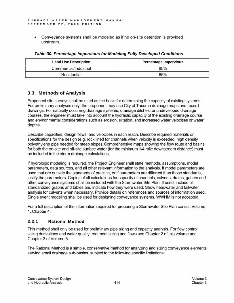
Conveyance systems shall be modeled as if no on-site detention is provided upstream.
Table 30. Percentage Impervious for Modeling Fully Developed Conditions
Land Use Description Percentage Impervious
Commercial/Industrial 85%Residential 65%
3.3 Methods of Analysis Proponent site surveys shall be used as the basis for determining the capacity of existing systems. For preliminary analyses only, the proponent may use City of Tacoma drainage maps and record drawings. For naturally occurring drainage systems, drainage ditches, or undeveloped drainage courses, the engineer must take into account the hydraulic capacity of the existing drainage course and environmental considerations such as erosion, siltation, and increased water velocities or water depths.
Describe capacities, design flows, and velocities in each reach. Describe required materials or specifications for the design (e.g. rock lined for channels when velocity is exceeded; high density polyethylene pipe needed for steep slope). Comprehensive maps showing the flow route and basins for both the on-site and off-site surface water (for the minimum 1/4 mile downstream distance) must be included in the storm drainage calculations.
If hydrologic modeling is required, the Project Engineer shall state methods, assumptions, model parameters, data sources, and all other relevant information to the analysis. If model parameters are used that are outside the standards of practice, or if parameters are different than those standards, justify the parameters. Copies of all calculations for capacity of channels, culverts, drains, gutters and other conveyance systems shall be included with the Stormwater Site Plan. If used, include all standardized graphs and tables and indicate how they were used. Show headwater and tailwater analysis for culverts when necessary. Provide details on references and sources of information used. Single event modeling shall be used for designing conveyance systems, WWHM is not accepted.
For a full description of the information required for preparing a Stormwater Site Plan consult Volume 1, Chapter 4.
3.3.1 Rational Method
This method shall only be used for preliminary pipe sizing and capacity analysis. For flow control sizing derivations and water quality treatment sizing and flows see Chapter 2 of this volume and Chapter 3 of Volume 5.
The Rational Method is a simple, conservative method for analyzing and sizing conveyance elements serving small drainage sub-basins, subject to the following specific limitations:
Conveyance System Design Volume 3 and Hydraulic Analysis Chapter 3 414
S U R F A C E W A T E R M A N A G E M E N T M A N U A L S E P T E M B E R 2 2 , 2 0 0 8 E D I T I O N
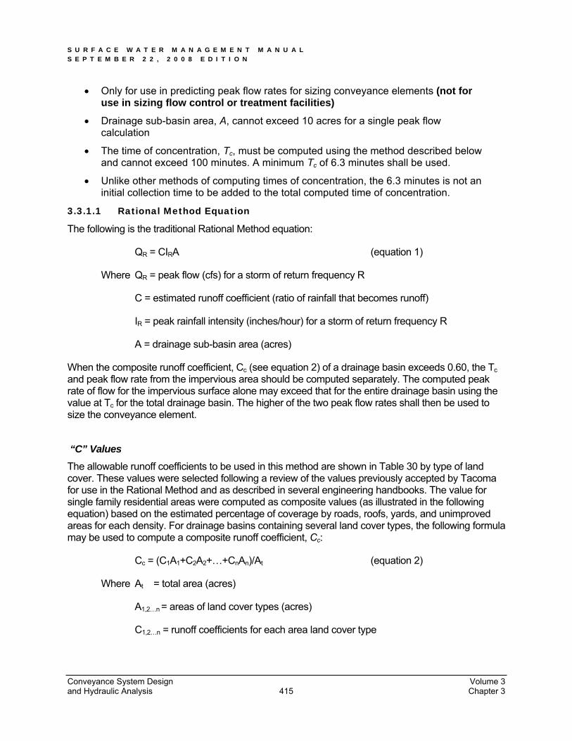
Only for use in predicting peak flow rates for sizing conveyance elements (not for use in sizing flow control or treatment facilities)
Drainage sub-basin area, A, cannot exceed 10 acres for a single peak flow calculation
The time of concentration, Tc, must be computed using the method described below and cannot exceed 100 minutes. A minimum Tc of 6.3 minutes shall be used.
Unlike other methods of computing times of concentration, the 6.3 minutes is not an initial collection time to be added to the total computed time of concentration.
3.3.1.1 Rational Method Equation
The following is the traditional Rational Method equation:
QR = CIRA (equation 1)
Where QR = peak flow (cfs) for a storm of return frequency R
C = estimated runoff coefficient (ratio of rainfall that becomes runoff)
IR = peak rainfall intensity (inches/hour) for a storm of return frequency R
A = drainage sub-basin area (acres)
When the composite runoff coefficient, Cc (see equation 2) of a drainage basin exceeds 0.60, the Tcand peak flow rate from the impervious area should be computed separately. The computed peak rate of flow for the impervious surface alone may exceed that for the entire drainage basin using the value at Tc for the total drainage basin. The higher of the two peak flow rates shall then be used to size the conveyance element.
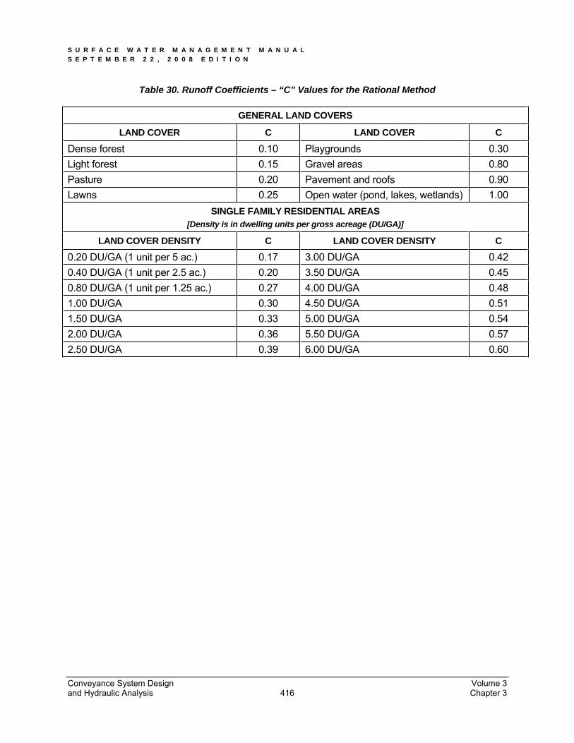
“C” Values The allowable runoff coefficients to be used in this method are shown in Table 30 by type of land cover. These values were selected following a review of the values previously accepted by Tacoma for use in the Rational Method and as described in several engineering handbooks. The value for single family residential areas were computed as composite values (as illustrated in the following equation) based on the estimated percentage of coverage by roads, roofs, yards, and unimproved areas for each density. For drainage basins containing several land cover types, the following formula may be used to compute a composite runoff coefficient, Cc:
Cc = (C1A1+C2A2+…+CnAn)/At (equation 2)
Where At = total area (acres)
A1,2…n = areas of land cover types (acres)
C1,2…n = runoff coefficients for each area land cover type
Conveyance System Design Volume 3 and Hydraulic Analysis Chapter 3 415
S U R F A C E W A T E R M A N A G E M E N T M A N U A L S E P T E M B E R 2 2 , 2 0 0 8 E D I T I O N
Table 30. Runoff Coefficients – “C” Values for the Rational Method
GENERAL LAND COVERS
LAND COVER C LAND COVER C
Dense forest 0.10 Playgrounds 0.30 Light forest 0.15 Gravel areas 0.80 Pasture 0.20 Pavement and roofs 0.90 Lawns 0.25 Open water (pond, lakes, wetlands) 1.00
SINGLE FAMILY RESIDENTIAL AREAS [Density is in dwelling units per gross acreage (DU/GA)]
LAND COVER DENSITY C LAND COVER DENSITY C
0.20 DU/GA (1 unit per 5 ac.) 0.17 3.00 DU/GA 0.42 0.40 DU/GA (1 unit per 2.5 ac.) 0.20 3.50 DU/GA 0.45 0.80 DU/GA (1 unit per 1.25 ac.) 0.27 4.00 DU/GA 0.48 1.00 DU/GA 0.30 4.50 DU/GA 0.51 1.50 DU/GA 0.33 5.00 DU/GA 0.54 2.00 DU/GA 0.36 5.50 DU/GA 0.57 2.50 DU/GA 0.39 6.00 DU/GA 0.60
Conveyance System Design Volume 3 and Hydraulic Analysis Chapter 3 416
S U R F A C E W A T E R M A N A G E M E N T M A N U A L S E P T E M B E R 2 2 , 2 0 0 8 E D I T I O N
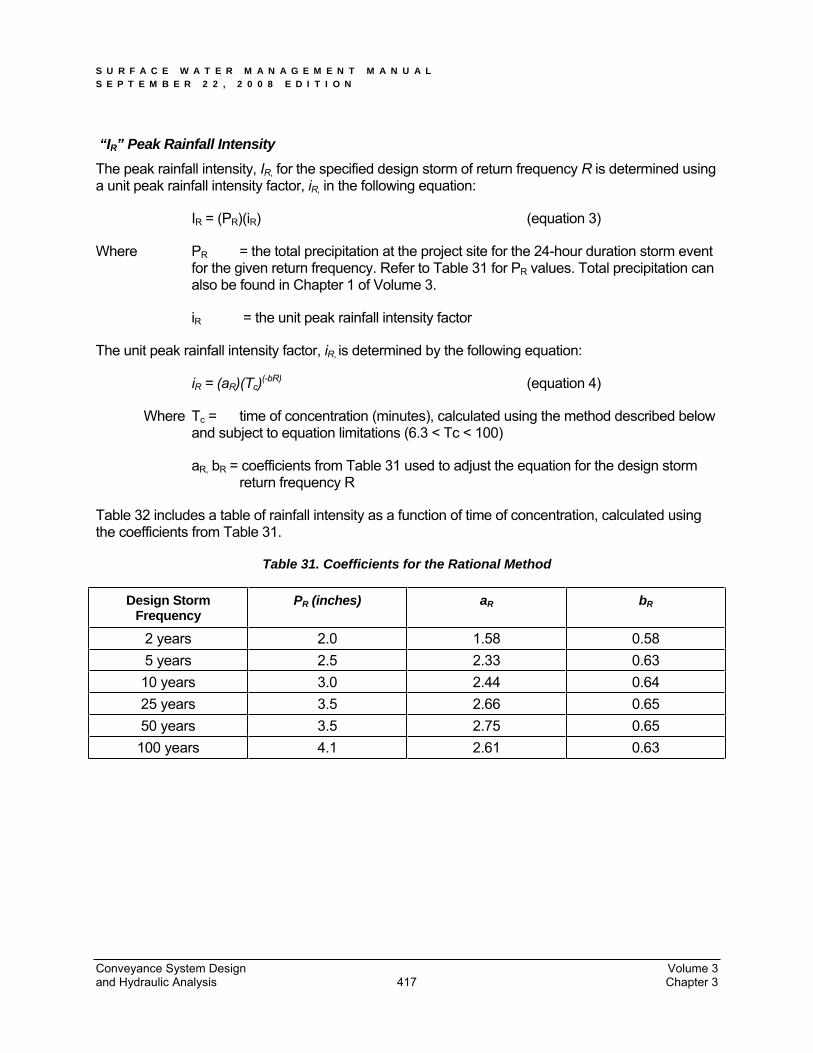
“IR” Peak Rainfall Intensity The peak rainfall intensity, IR, for the specified design storm of return frequency R is determined using a unit peak rainfall intensity factor, iR, in the following equation:
IR = (PR)(iR) (equation 3)
Where PR = the total precipitation at the project site for the 24-hour duration storm event for the given return frequency. Refer to Table 31 for PR values. Total precipitation can also be found in Chapter 1 of Volume 3.
iR = the unit peak rainfall intensity factor
The unit peak rainfall intensity factor, iR, is determined by the following equation:
iR = (aR)(Tc)(-bR) (equation 4)
Where Tc = time of concentration (minutes), calculated using the method described below and subject to equation limitations (6.3 < Tc < 100)
aR, bR = coefficients from Table 31 used to adjust the equation for the design storm return frequency R
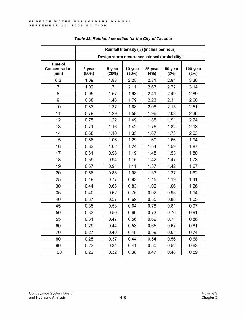
Table 32 includes a table of rainfall intensity as a function of time of concentration, calculated using the coefficients from Table 31.
Table 31. Coefficients for the Rational Method
Design Storm Frequency
PR (inches) aR bR
2 years 2.0 1.58 0.58 5 years 2.5 2.33 0.63 10 years 3.0 2.44 0.64 25 years 3.5 2.66 0.65 50 years 3.5 2.75 0.65 100 years 4.1 2.61 0.63
Conveyance System Design Volume 3 and Hydraulic Analysis Chapter 3 417
S U R F A C E W A T E R M A N A G E M E N T M A N U A L S E P T E M B E R 2 2 , 2 0 0 8 E D I T I O N
Table 32. Rainfall Intensities for the City of Tacoma
Rainfall Intensity (IR) (inches per hour)
Design storm recurrence interval (probability)
Time of Concentration
(min) 2-year (50%)
5-year (20%)
10-year (10%)
25-year(4%)
50-year (2%)
100-year (1%)
6.3 1.09 1.83 2.25 2.81 2.91 3.36 7 1.02 1.71 2.11 2.63 2.72 3.14 8 0.95 1.57 1.93 2.41 2.49 2.89 9 0.88 1.46 1.79 2.23 2.31 2.68 10 0.83 1.37 1.68 2.08 2.15 2.51 11 0.79 1.29 1.58 1.96 2.03 2.36 12 0.75 1.22 1.49 1.85 1.91 2.24 13 0.71 1.16 1.42 1.76 1.82 2.13 14 0.68 1.10 1.35 1.67 1.73 2.03 15 0.66 1.06 1.29 1.60 1.66 1.94 16 0.63 1.02 1.24 1.54 1.59 1.87 17 0.61 0.98 1.19 1.48 1.53 1.80 18 0.59 0.94 1.15 1.42 1.47 1.73 19 0.57 0.91 1.11 1.37 1.42 1.67 20 0.56 0.88 1.08 1.33 1.37 1.62 25 0.49 0.77 0.93 1.15 1.19 1.41 30 0.44 0.68 0.83 1.02 1.06 1.26 35 0.40 0.62 0.75 0.92 0.95 1.14 40 0.37 0.57 0.69 0.85 0.88 1.05 45 0.35 0.53 0.64 0.78 0.81 0.97 50 0.33 0.50 0.60 0.73 0.76 0.91 55 0.31 0.47 0.56 0.69 0.71 0.86 60 0.29 0.44 0.53 0.65 0.67 0.81 70 0.27 0.40 0.48 0.59 0.61 0.74 80 0.25 0.37 0.44 0.54 0.56 0.68 90 0.23 0.34 0.41 0.50 0.52 0.63 100 0.22 0.32 0.38 0.47 0.48 0.59
Conveyance System Design Volume 3 and Hydraulic Analysis Chapter 3 418
S U R F A C E W A T E R M A N A G E M E N T M A N U A L S E P T E M B E R 2 2 , 2 0 0 8 E D I T I O N
“Tc” Time of Concentration The time of concentration is defined as the time it takes runoff to travel overland (from the onset of precipitation) from the most hydraulically distant location in the drainage basin to the point of discharge.
Due to the mathematical limits of the equation coefficients, values of Tc less than 6.3 minutes or greater than 100 minutes cannot be used. Therefore, real values of Tc less than 6.3 minutes must be assumed to be equal to 6.3 minutes, and values greater than 100 minutes must be assumed to be equal to 100 minutes.
Tc is computed by summation of the travel times Tt of overland flow across separate flowpath segments. The equation for time of concentration is:
Tc = T1 + T2 + … + Tn (equation 5)
Where T1,2…n = travel time for consecutive flowpath segments with different categories or flowpath slope
Travel time for each segment, t, is computed using the following equation:
Tt = L/60V (equation 6)
where Tt = travel time (minutes)
Tt through an open water body (such as a pond) shall be assumed to be zero with this method.
Tt = Travel time for each segment (ft)
L = the distance of flow across a given segment (feet)
V = average velocity (ft/s) across the land cover =
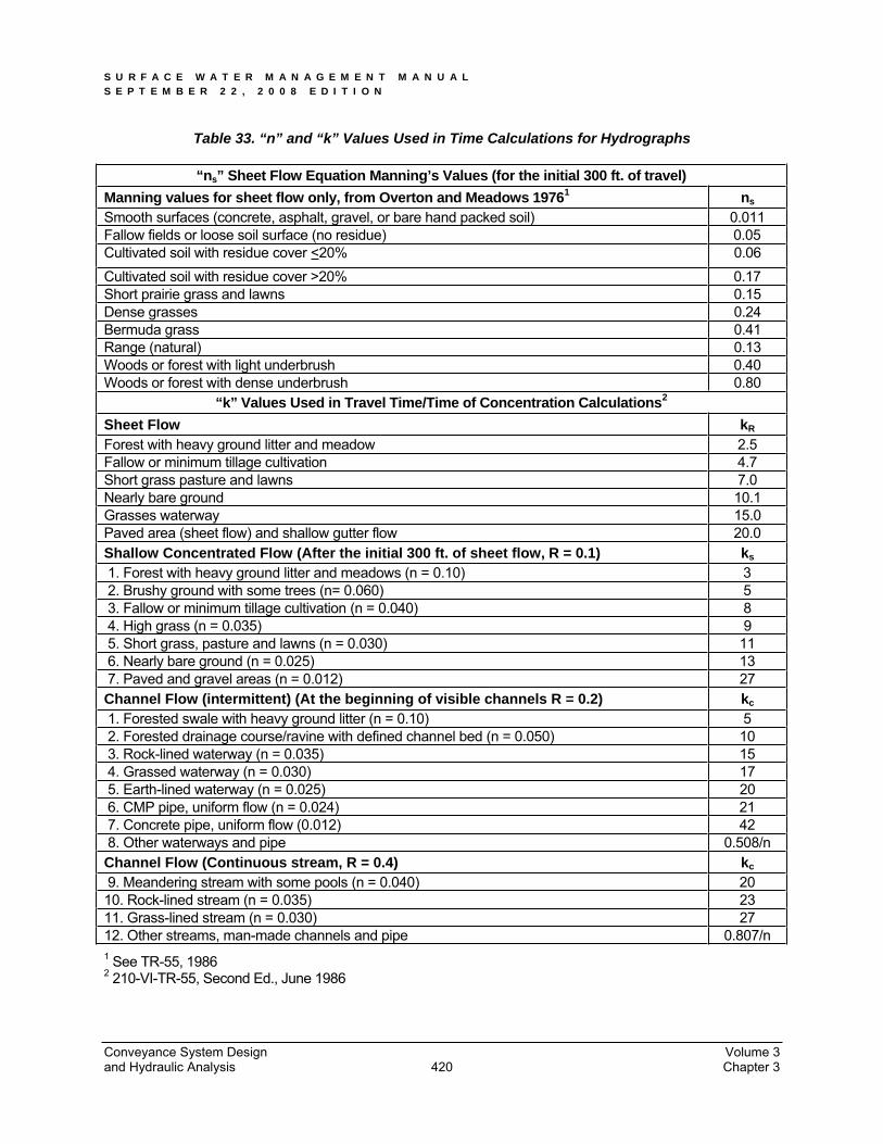
Where kR = time of concentration velocity factor; see Table 33.
s0 = slope of flowpath (feet/feet)
Conveyance System Design Volume 3 and Hydraulic Analysis Chapter 3 419
S U R F A C E W A T E R M A N A G E M E N T M A N U A L S E P T E M B E R 2 2 , 2 0 0 8 E D I T I O N
Table 33. “n” and “k” Values Used in Time Calculations for Hydrographs
“ns” Sheet Flow Equation Manning’s Values (for the initial 300 ft. of travel) Manning values for sheet flow only, from Overton and Meadows 19761 ns
Smooth surfaces (concrete, asphalt, gravel, or bare hand packed soil) 0.011 Fallow fields or loose soil surface (no residue) 0.05Cultivated soil with residue cover <20% 0.06Cultivated soil with residue cover >20% 0.17Short prairie grass and lawns 0.15Dense grasses 0.24Bermuda grass 0.41Range (natural) 0.13Woods or forest with light underbrush 0.40Woods or forest with dense underbrush 0.80
“k” Values Used in Travel Time/Time of Concentration Calculations2
Sheet Flow kR
Forest with heavy ground litter and meadow 2.5Fallow or minimum tillage cultivation 4.7Short grass pasture and lawns 7.0Nearly bare ground 10.1Grasses waterway 15.0Paved area (sheet flow) and shallow gutter flow 20.0Shallow Concentrated Flow (After the initial 300 ft. of sheet flow, R = 0.1) ks
1. Forest with heavy ground litter and meadows (n = 0.10) 3 2. Brushy ground with some trees (n= 0.060) 5 3. Fallow or minimum tillage cultivation (n = 0.040) 8 4. High grass (n = 0.035) 9 5. Short grass, pasture and lawns (n = 0.030) 11 6. Nearly bare ground (n = 0.025) 13 7. Paved and gravel areas (n = 0.012) 27Channel Flow (intermittent) (At the beginning of visible channels R = 0.2) kc
1. Forested swale with heavy ground litter (n = 0.10) 5 2. Forested drainage course/ravine with defined channel bed (n = 0.050) 10 3. Rock-lined waterway (n = 0.035) 15 4. Grassed waterway (n = 0.030) 17 5. Earth-lined waterway (n = 0.025) 20 6. CMP pipe, uniform flow (n = 0.024) 21 7. Concrete pipe, uniform flow (0.012) 42 8. Other waterways and pipe 0.508/n Channel Flow (Continuous stream, R = 0.4) kc
9. Meandering stream with some pools (n = 0.040) 2010. Rock-lined stream (n = 0.035) 2311. Grass-lined stream (n = 0.030) 2712. Other streams, man-made channels and pipe 0.807/n 1 See TR-55, 1986 2 210-VI-TR-55, Second Ed., June 1986
Conveyance System Design Volume 3 and Hydraulic Analysis Chapter 3 420

S U R F A C E W A T E R M A N A G E M E N T M A N U A L S E P T E M B E R 2 2 , 2 0 0 8 E D I T I O N
3.4 Pipes, Culverts and Open Channels This section presents the methods, criteria and details for analysis and design of pipe systems, culverts, and open channel conveyance systems.
3.4.1 Pipe Systems
Pipe systems are networks of storm drain pipes, catch basins, manholes, inlets, and outfalls, designed and constructed to convey surface water. The hydraulic analysis of flow in storm drainage pipes typically is limited to gravity flow; however in analyzing existing systems it may be necessary to address pressurized conditions. A properly designed pipe system will maximize hydraulic efficiency by utilizing proper material, slope, and pipe size.
3.4.1.1 Design Flows
Design flows for sizing or assessing the capacity of pipe systems shall be determined using the hydrologic analysis methods described in this chapter. Approved single event models described in Chapter 1 of this volume may also be used to determine design flows. The design event is described in Section 3.2. Pipe systems shall be designed to convey the design event without surcharging (water depth in pipe shall not exceed 90% of the pipe diameter).
3.4.1.2 Conveyance Capacity
Two methods of hydraulic analysis using Manning’s Equation are required by the City of Tacoma for the analysis of pipe systems. First, the Uniform Flow Analysis method is used for preliminary design and analysis of pipe systems. Second, the Backwater Analysis method is used to analyze both proposed and existing pipe systems to verify adequate capacity. See Section 3.2 for the required design events for pipe systems. For projects in the Tideflats area of Tacoma, refer to Section 3.2.1 – Additional Design Criteria for any additional required analysis to be completed.
Uniform Flow Analysis This method is typically used for preliminary sizing of new pipe systems to convey the design flow as calculated from the required design event from Section 3.2.
Assumptions:
Flow is uniform in each pipe (i.e., depth and velocity remain constant throughout the pipe for a given flow).
Friction head loss in the pipe barrel alone controls capacity. Other head losses (e.g., entrance, exit, junction, etc.) and any backwater effects or inlet control conditions are not specifically addressed.
All pipes shall be designed for fully developed conditions. The fully developed conditions shall be derived from the percentages of impervious area provided in Table 34.
Conveyance System Design Volume 3 and Hydraulic Analysis Chapter 3 421
S U R F A C E W A T E R M A N A G E M E N T M A N U A L S E P T E M B E R 2 2 , 2 0 0 8 E D I T I O N
Table 34. Percentage Impervious for Modeling Fully Developed Conditions
Land Use Description1 % Impervious
Commercial/Industrial 85Residential 65
1 For the land use descriptions, roads are included in the percentage impervious.
When a project is proposed for the Tideflats area in Tacoma, the site grades and storm drainage system elevations shall be checked against tidal records to evaluate the ability of the system to carry the additional flow via a backwater analysis. Tides can be as much as 2 feet higher than predicted due to influence of low barometric pressure. The 25-year, 24-hour event should be analyzed at mean high tide (+4.64 feet using current City datum). The pipe should be able to convey the 25-year, 24-hour event at mean high tide without surcharging. The 100-year, 24-hour event at mean high tide should be analyzed and if flooding occurs, the flodding should be mapped. Environmental Services will evaluate and determine the acceptability of this type of localized flooding.
All pipes shall be modeled as if no on-site detention is provided up-stream.
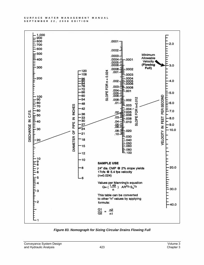
Each pipe within the system shall be sized and sloped such that its barrel capacity at normal full flow is equal to or greater than the design flow calculated from the appropriate design storm as identified in Section 3.2. The nomographs in Figure 83 can be used for approximate sizing of the pipes or Manning’s Equation can be solved for pipe size directly:
2/13/249.1 SRn
V (equation 7)
or use the continuity equation, Q = A•V, such that
2/13/249.1 SARn
Q (equation 8)
Where Q = discharge (cfs)
V = velocity (fps)
A = area (sf)
n = Manning’s roughness coefficient; see Table 35
R = hydraulic radius = area/wetted perimeter
S = slope of the energy grade line (ft/ft)
Conveyance System Design Volume 3 and Hydraulic Analysis Chapter 3 422
S U R F A C E W A T E R M A N A G E M E N T M A N U A L S E P T E M B E R 2 2 , 2 0 0 8 E D I T I O N
Figure 83. Nomograph for Sizing Circular Drains Flowing Full
Conveyance System Design Volume 3 and Hydraulic Analysis Chapter 3 423
S U R F A C E W A T E R M A N A G E M E N T M A N U A L S E P T E M B E R 2 2 , 2 0 0 8 E D I T I O N
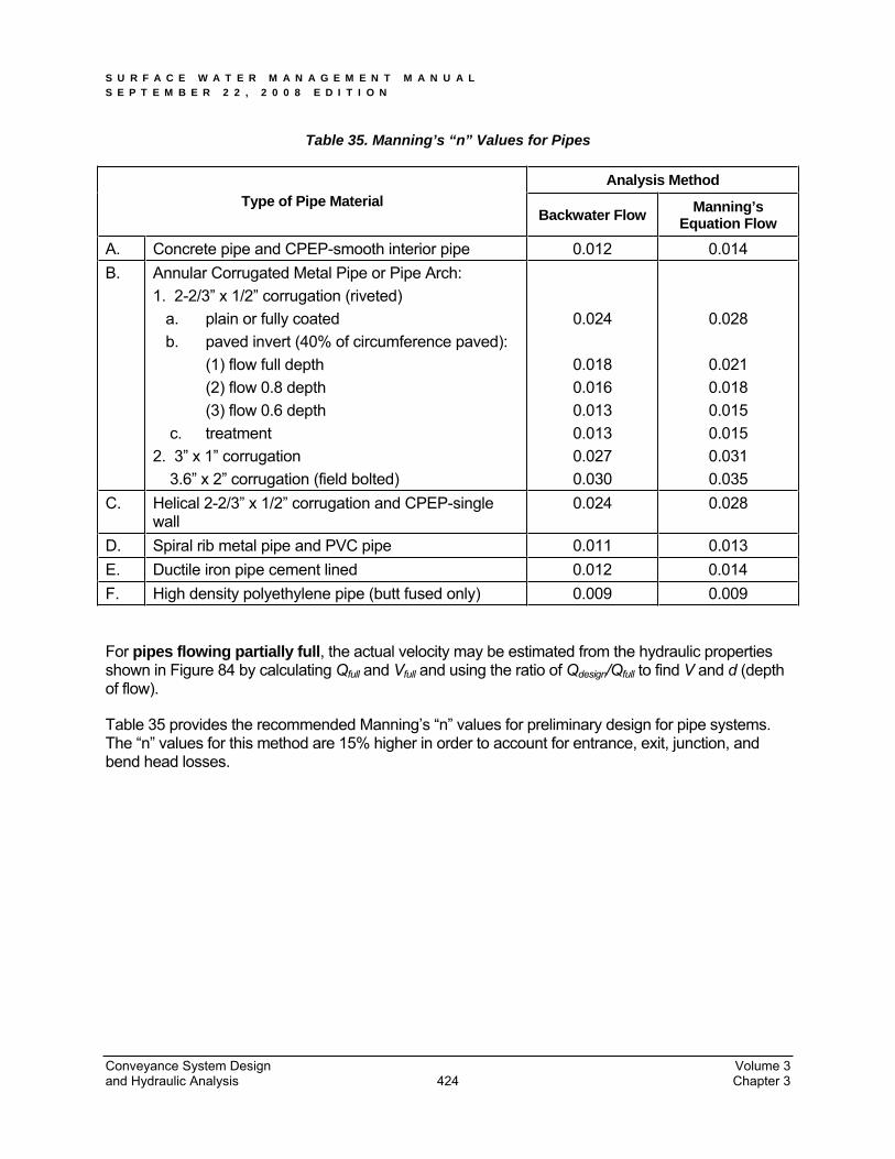
Table 35. Manning’s “n” Values for Pipes
Analysis Method Type of Pipe Material
Backwater Flow Manning’s Equation Flow
A. Concrete pipe and CPEP-smooth interior pipe 0.012 0.014B. Annular Corrugated Metal Pipe or Pipe Arch:
1. 2-2/3” x 1/2” corrugation (riveted) a. plain or fully coated b. paved invert (40% of circumference paved): (1) flow full depth (2) flow 0.8 depth (3) flow 0.6 depth c. treatment 2. 3” x 1” corrugation 3.6” x 2” corrugation (field bolted)
0.024
0.018 0.016 0.013 0.013 0.027 0.030
0.028
0.021 0.018 0.015 0.015 0.031 0.035
C. Helical 2-2/3” x 1/2” corrugation and CPEP-single wall
0.024 0.028
D. Spiral rib metal pipe and PVC pipe 0.011 0.013 E. Ductile iron pipe cement lined 0.012 0.014 F. High density polyethylene pipe (butt fused only) 0.009 0.009
For pipes flowing partially full, the actual velocity may be estimated from the hydraulic properties shown in Figure 84 by calculating Qfull and Vfull and using the ratio of Qdesign/Qfull to find V and d (depth of flow).
Table 35 provides the recommended Manning’s “n” values for preliminary design for pipe systems. The “n” values for this method are 15% higher in order to account for entrance, exit, junction, and bend head losses.
Conveyance System Design Volume 3 and Hydraulic Analysis Chapter 3 424

S U R F A C E W A T E R M A N A G E M E N T M A N U A L S E P T E M B E R 2 2 , 2 0 0 8 E D I T I O N
Figure 84. Circular Channel Ratios
Conveyance System Design Volume 3 and Hydraulic Analysis Chapter 3 425
S U R F A C E W A T E R M A N A G E M E N T M A N U A L S E P T E M B E R 2 2 , 2 0 0 8 E D I T I O N
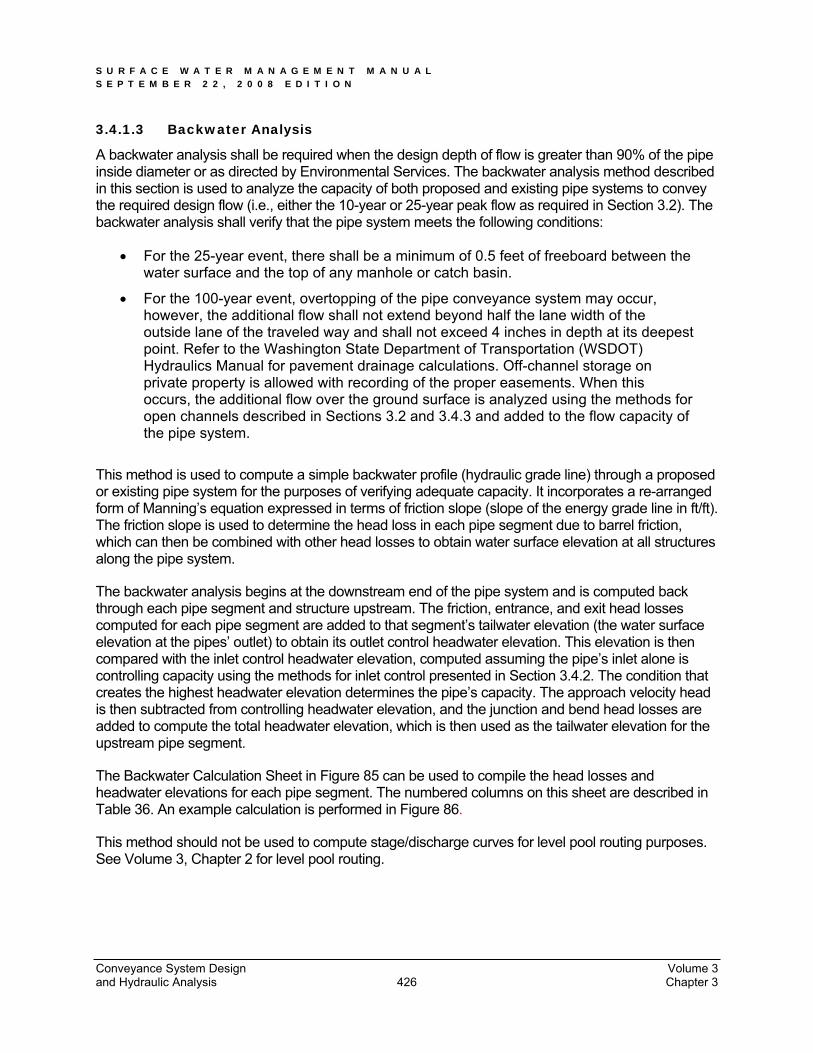
3.4.1.3 Backwater Analysis
A backwater analysis shall be required when the design depth of flow is greater than 90% of the pipe inside diameter or as directed by Environmental Services. The backwater analysis method described in this section is used to analyze the capacity of both proposed and existing pipe systems to convey the required design flow (i.e., either the 10-year or 25-year peak flow as required in Section 3.2). The backwater analysis shall verify that the pipe system meets the following conditions:
For the 25-year event, there shall be a minimum of 0.5 feet of freeboard between the water surface and the top of any manhole or catch basin.
For the 100-year event, overtopping of the pipe conveyance system may occur, however, the additional flow shall not extend beyond half the lane width of the outside lane of the traveled way and shall not exceed 4 inches in depth at its deepest point. Refer to the Washington State Department of Transportation (WSDOT) Hydraulics Manual for pavement drainage calculations. Off-channel storage on private property is allowed with recording of the proper easements. When this occurs, the additional flow over the ground surface is analyzed using the methods for open channels described in Sections 3.2 and 3.4.3 and added to the flow capacity of the pipe system.
This method is used to compute a simple backwater profile (hydraulic grade line) through a proposed or existing pipe system for the purposes of verifying adequate capacity. It incorporates a re-arranged form of Manning’s equation expressed in terms of friction slope (slope of the energy grade line in ft/ft). The friction slope is used to determine the head loss in each pipe segment due to barrel friction, which can then be combined with other head losses to obtain water surface elevation at all structures along the pipe system.
The backwater analysis begins at the downstream end of the pipe system and is computed back through each pipe segment and structure upstream. The friction, entrance, and exit head losses computed for each pipe segment are added to that segment’s tailwater elevation (the water surface elevation at the pipes’ outlet) to obtain its outlet control headwater elevation. This elevation is then compared with the inlet control headwater elevation, computed assuming the pipe’s inlet alone is controlling capacity using the methods for inlet control presented in Section 3.4.2. The condition that creates the highest headwater elevation determines the pipe’s capacity. The approach velocity head is then subtracted from controlling headwater elevation, and the junction and bend head losses are added to compute the total headwater elevation, which is then used as the tailwater elevation for the upstream pipe segment.
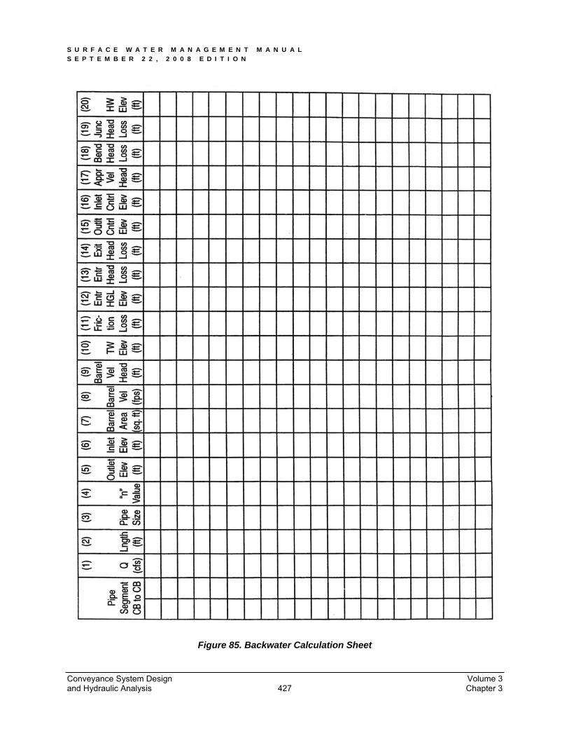
The Backwater Calculation Sheet in Figure 85 can be used to compile the head losses and headwater elevations for each pipe segment. The numbered columns on this sheet are described in Table 36. An example calculation is performed in Figure 86.
This method should not be used to compute stage/discharge curves for level pool routing purposes. See Volume 3, Chapter 2 for level pool routing.
Conveyance System Design Volume 3 and Hydraulic Analysis Chapter 3 426
S U R F A C E W A T E R M A N A G E M E N T M A N U A L S E P T E M B E R 2 2 , 2 0 0 8 E D I T I O N
Figure 85. Backwater Calculation Sheet
Conveyance System Design Volume 3 and Hydraulic Analysis Chapter 3 427
S U R F A C E W A T E R M A N A G E M E N T M A N U A L S E P T E M B E R 2 2 , 2 0 0 8 E D I T I O N
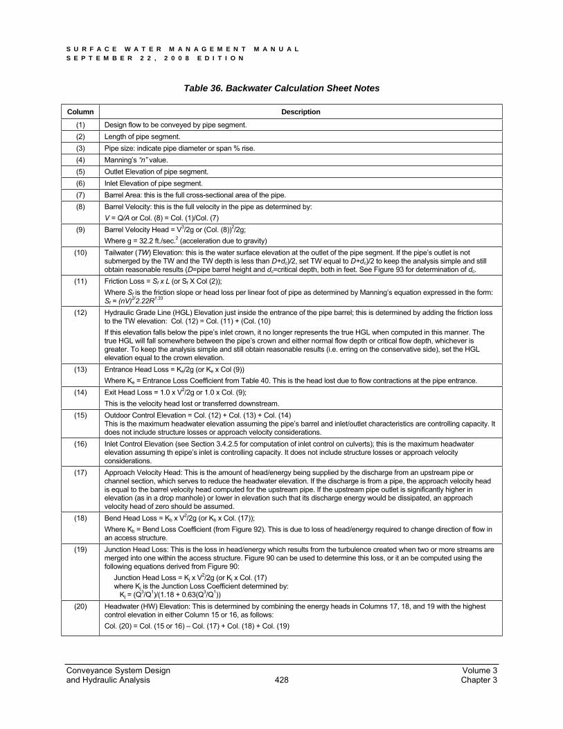
Table 36. Backwater Calculation Sheet Notes
Column Description
(1) Design flow to be conveyed by pipe segment. (2) Length of pipe segment. (3) Pipe size: indicate pipe diameter or span % rise. (4) Manning’s “n” value. (5) Outlet Elevation of pipe segment. (6) Inlet Elevation of pipe segment. (7) Barrel Area: this is the full cross-sectional area of the pipe. (8) Barrel Velocity: this is the full velocity in the pipe as determined by:
V = Q/A or Col. (8) = Col. (1)/Col. (7) (9) Barrel Velocity Head = V3/2g or (Col. (8))2/2g;
Where g = 32.2 ft./sec.2 (acceleration due to gravity) (10) Tailwater (TW) Elevation: this is the water surface elevation at the outlet of the pipe segment. If the pipe’s outlet is not
submerged by the TW and the TW depth is less than D+dc)/2, set TW equal to D+dc)/2 to keep the analysis simple and still obtain reasonable results (D=pipe barrel height and dc=critical depth, both in feet. See Figure 93 for determination of dc.
(11) Friction Loss = Sf x L (or Sf X Col (2)); Where Sf is the friction slope or head loss per linear foot of pipe as determined by Manning’s equation expressed in the form: Sf = (nV)2/2.22R1.33
(12) Hydraulic Grade Line (HGL) Elevation just inside the entrance of the pipe barrel; this is determined by adding the friction loss to the TW elevation: Col. (12) = Col. (11) + (Col. (10) If this elevation falls below the pipe’s inlet crown, it no longer represents the true HGL when computed in this manner. The true HGL will fall somewhere between the pipe’s crown and either normal flow depth or critical flow depth, whichever is greater. To keep the analysis simple and still obtain reasonable results (i.e. erring on the conservative side), set the HGL elevation equal to the crown elevation.
(13) Entrance Head Loss = Ke/2g (or Ke x Col (9)) Where Ke = Entrance Loss Coefficient from Table 40. This is the head lost due to flow contractions at the pipe entrance.
(14) Exit Head Loss = 1.0 x V2/2g or 1.0 x Col. (9); This is the velocity head lost or transferred downstream.
(15) Outdoor Control Elevation = Col. (12) + Col. (13) + Col. (14) This is the maximum headwater elevation assuming the pipe’s barrel and inlet/outlet characteristics are controlling capacity. Itdoes not include structure losses or approach velocity considerations.
(16) Inlet Control Elevation (see Section 3.4.2.5 for computation of inlet control on culverts); this is the maximum headwater elevation assuming th epipe’s inlet is controlling capacity. It does not include structure losses or approach velocity considerations.
(17) Approach Velocity Head: This is the amount of head/energy being supplied by the discharge from an upstream pipe or channel section, which serves to reduce the headwater elevation. If the discharge is from a pipe, the approach velocity head is equal to the barrel velocity head computed for the upstream pipe. If the upstream pipe outlet is significantly higher in elevation (as in a drop manhole) or lower in elevation such that its discharge energy would be dissipated, an approach velocity head of zero should be assumed.
(18) Bend Head Loss = Kb x V2/2g (or Kb x Col. (17)); Where Kb = Bend Loss Coefficient (from Figure 92). This is due to loss of head/energy required to change direction of flow in an access structure.
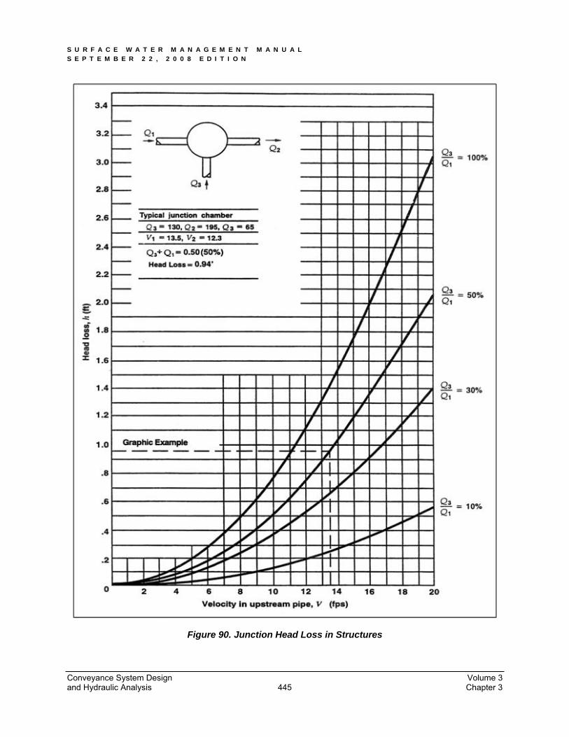
(19) Junction Head Loss: This is the loss in head/energy which results from the turbulence created when two or more streams aremerged into one within the access structure. Figure 90 can be used to determine this loss, or it an be computed using the following equations derived from Figure 90: Junction Head Loss = Kj x V2/2g (or Kj x Col. (17) where Kj is the Junction Loss Coefficient determined by: Kj = (Q3/Q1)/(1.18 + 0.63(Q3/Q1))
(20) Headwater (HW) Elevation: This is determined by combining the energy heads in Columns 17, 18, and 19 with the highest control elevation in either Column 15 or 16, as follows: Col. (20) = Col. (15 or 16) – Col. (17) + Col. (18) + Col. (19)
Conveyance System Design Volume 3 and Hydraulic Analysis Chapter 3 428
S U R F A C E W A T E R M A N A G E M E N T M A N U A L S E P T E M B E R 2 2 , 2 0 0 8 E D I T I O N
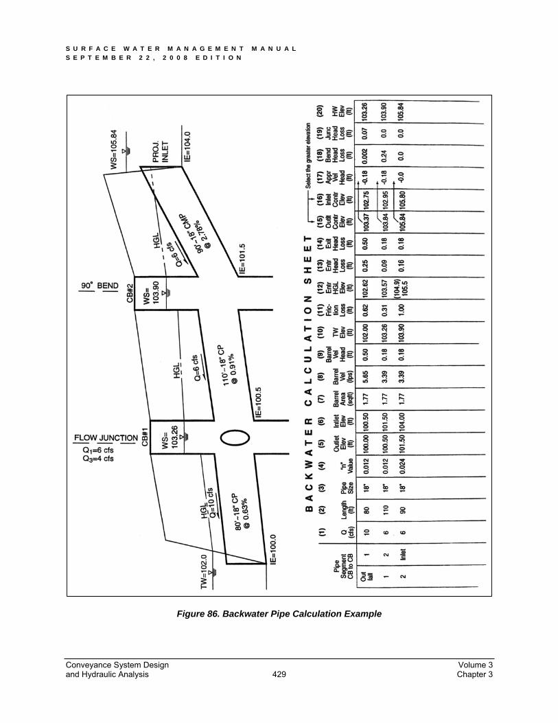
Figure 86. Backwater Pipe Calculation Example
Conveyance System Design Volume 3 and Hydraulic Analysis Chapter 3 429

S U R F A C E W A T E R M A N A G E M E N T M A N U A L S E P T E M B E R 2 2 , 2 0 0 8 E D I T I O N
3.4.1.4 Inlet Grate Capacity
The Washington State Department of Transportation (WSDOT) Hydraulics Manual can be used in determining the capacity of inlet grates when capacity is of concern. When verifying capacity, assume:
Grate areas on slopes are 80 percent free of debris, and “vaned” grates are 95 percent free.
Grate areas in sags or low spots are 50 percent free of debris, and “vaned” grates, 75 percent free.
3.4.1.5 Pipe Materials
All pipe material, joints, and protective treatment shall be in accordance with Section 9.05 of the latest version of the WSDOT/APWA Standard Specifications and AASHTO and ASTM treatment standards as amended and as provided in this manual by the City of Tacoma.
All storm drainage pipe to be installed in public right-of-ways or as a connection to the municipal system shall be either:
Rubber-gasketed concrete pipe (12-inch maximum diameter), or
Rubber gasketed reinforced concrete pipe, minimum 12-inch diameter, or
Polyvinyl chloride (PVC) sewer pipe (ASTM D3034 for PVC less than or equal to 15-inches or ASTM F679 for PVC greater than 15-inch), or
Smooth interior, watertight, corrugated high-density polyethylene pipe (CPEP). Smooth interior CPEP shall have watertight joints meeting ASTM D3212 with gaskets meeting the requirements of ASTM F477. 4-inch through 10-inch pipe shall meet AASHTO M252, Type S; and 12-inch through 60-inch pipe shall meet AASHTO M294, Type S or ASTM F2306. All CPEP fittings shall conform to AASHTO M252, AASHTO M294, or ASTM F2306.
High-density polyethylene pipe (HDPE). Pipe must comply with requirement of Type III C5P34 per ASTM D1248 and have the PPI recommended designation of PE3408 and have an ASTM D3350 cell classification of 345434C or 345534C. Pipe shall have a manufacturer’s recommended hydrostatic design stress rating of 800 psi based on a material with a 1600 psi design basis determined in accordance with ASTM D2837-69. Pipe shall have a suggested design working pressure of 50 psi at 73.4 degrees F and SDR of 17.5. Designs utilizing HDPE pipe shall include considerations of the material’s thermal expansion/contraction properties for anchoring.
Ductile iron (class 50 or 52).
Galvanized, aluminized, and/or corrugated iron or steel pipes are not allowed within the public right-of-way or as a connection to the Municipal system.
If other pipe materials are to be used in projects not within the public right-of-way or as a connection to the municipal system, they shall meet the minimum requirements of the following and shall have prior City approval:
Conveyance System Design Volume 3 and Hydraulic Analysis Chapter 3 430
S U R F A C E W A T E R M A N A G E M E N T M A N U A L S E P T E M B E R 2 2 , 2 0 0 8 E D I T I O N
Corrugated aluminum pipe (12-gauge or thicker)
Aluminum spiral rib pipe (12-gauge or thicker)
Aluminized Type 2 corrugated steel (meeting AASHTO treatment M274 and M 56, 12-gauge or thicker)
Corrugated high density polyethylene pipe (CPEP) - single wall, fully corrugated meeting AASHTO standard M-252 (permitted only outside public right-of-way and for use in temporary storm sewer systems and as downspout/footing/yard drain collectors on private property)
Polyvinyl chloride (PVC) sewer pipe (SDR 35, meeting requirements of ASTM D3034)
3.4.1.6 Pipe Sizes
The following pipe sizes shall be used for pipe systems to be maintained by the City of Tacoma: 12-inch, 15-inch, 18-inch, 21-inch, 24-inch, and 30-inch.
Pipes smaller than 12-inch may only be used for privately maintained systems, or to match the diameter of existing downstream mains, or as approved in writing by Environmental Services.
Catch basin leads shall be a minimum of 12-inch.
Roof drains may use pipe as small as 4 inch, and small driveway drains may use pipe as small as 6-inch. Pipes under 10-inch may require capacity analysis if requested by Environmental Services.
For pipes larger than 30-inch increasing increments of 6-inch intervals shall be used (36-inch, 42-inch, 48-inch, etc.).
3.4.1.7 Changes in Pipe Sizes
Pipe direction changes or size increases or decreases are only allowed at manholes and catch basins.
Where a minimal fall is necessary between inlet and outlet pipes in a structure, pipes must be aligned vertically by one of the following in order of preference:
a. Match pipe crowns
b. Match 80% diameters of pipes
c. Match pipe inverts or use City approved drop inlet connection
3.4.1.8 Pipe Alignment and Depth
Pipes must be laid true to line and grade with no curves, bends, or deflections in any direction.
Exception: Vertical deflections in HDPE and ductile iron pipe with flanged restrained mechanical joint bends (not greater than 30%) on steep slopes are allowed provided the pipe adequately drains, with a minimum velocity of 2 feet per second (fps).
Conveyance System Design Volume 3 and Hydraulic Analysis Chapter 3 431
S U R F A C E W A T E R M A N A G E M E N T M A N U A L S E P T E M B E R 2 2 , 2 0 0 8 E D I T I O N
A break in grade or alignment or changes in pipe material shall occur only at catch basins or manholes.
For the standard main alignment refer to the Public Works Design Manual.
The standard depth for new mains measures six (6) feet from the center of the pipe to the main street surface.
The project engineer shall consult with the City for the potential of a future extension of the storm system. In this case, the City may require modifications to the depth or alignment.
Connections to the main shall be at 90 . Slight variations may be allowed.
Pipes shall be allowed to cross under retaining walls as specifically approved in writing by Environmental Services when no other reasonable alternatives exist.
3.4.1.9 Pipe Slopes and Velocities
The slope of the pipe shall be set so that a minimum velocity of 2 feet per second can be maintained at full flow.
A minimum slope for all pipes shall be 0.5% (under certain circumstances, a minimum slope of 0.3% may be allowed with prior approval in writing from Environmental Services).
Maximum slopes, velocities, and anchor spacings are shown in Table 37. If velocities exceed 15 feet per second for the conveyance system design event described in Section 3.2, provide anchors and/or restrained joints at bends and junctions.
3.4.1.10 Pipes on Steep Slopes
Slopes 20% or greater shall require all drainage to be piped from the top to the bottom in High Density Polyethylene (HDPE) pipe (butt-fused) or ductile iron pipe welded or mechanically restrained. Additional anchoring design is required for these pipes.
Above-ground installation is required on slopes greater than 40% to minimize disturbance to steep slopes, unless otherwise approved in writing by Environmental Services.
HDPE pipe systems longer than 100 feet must be anchored at the upstream end if the slope exceeds 20% or as required by Environmental Services.
Above ground installations of HDPE shall address the high thermal expansion/contraction coefficient of the pipe material. An analysis shall be completed to demonstrate that the system as designed will tolerate the thermal expansion of the pipe material.
Conveyance System Design Volume 3 and Hydraulic Analysis Chapter 3 432

S U R F A C E W A T E R M A N A G E M E N T M A N U A L S E P T E M B E R 2 2 , 2 0 0 8 E D I T I O N
Table 37. Maximum Pipe Slopes, Velocities and Anchor Requirements
Pipe Material Pipe Slope Above Which Pipe
Anchors Required and Minimum Anchor Spacing
Max. Slope Allowed
Max. Velocity @ Full Flow
Spiral Rib(1), PVC(1),CPEP-singlewall
20%(1 anchor per 100 L.F. of pipe)
30%(3) 30 fps
Concrete(1) or CPEP- smooth interior(1)
10%(1 anchor per 50 L.F. of pipe)
20%(3) 30 fps
Ductile Iron(4) 40%(1 anchor per pipe section)
None None
HDPE(2) 50%(1 anchor per 100 L.F. of pipe – cross slope installations may be allowed with additional anchoring and analysis)
None None
Notes: (1) Not allowed in landslide hazard areas. (2) Butt-fused pipe joints required. Above-ground installation is required on slopes greater than 40% to minimize disturbance to steep slopes. (3) Maximum slope of 200% allowed for these pipe materials with no joints (one section) if structures are provided at each end and the pipes are property grouted or otherwise restrained to the structures. (4) Restrained joints required on slopes greater than 25%. Above-ground installation is required on slopes greater than 40% to minimize disturbance to steep slopes.
KEY: PVC = Polyvinyl chloride pipe CPEP = Corrugated high density polyethylene pipe HDPE = High density polyethylene pipe
3.4.1.11 Structures
For the purposes of this Manual, all catch basins and manholes shall meet WSDOT standards such as Type 1L, Type 1, and Type 2. Table 38 presents the structures and pipe sizes allowed by size of structure.
Conveyance System Design Volume 3 and Hydraulic Analysis Chapter 3 433
S U R F A C E W A T E R M A N A G E M E N T M A N U A L S E P T E M B E R 2 2 , 2 0 0 8 E D I T I O N
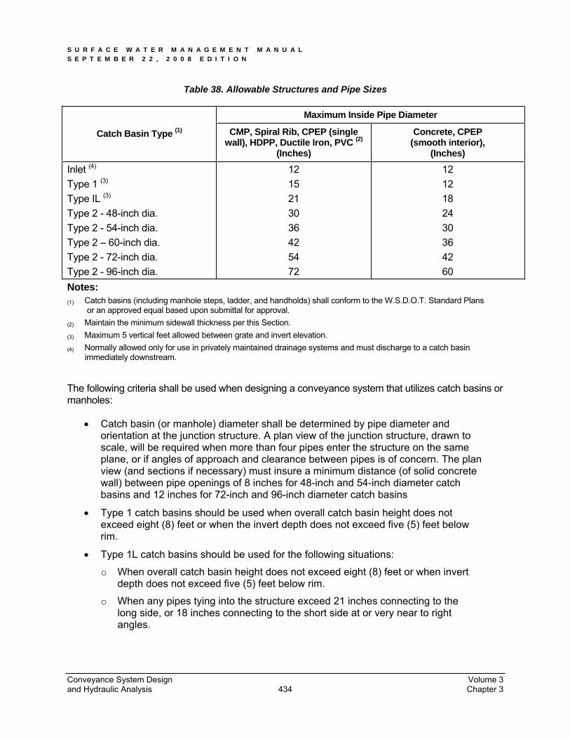
Table 38. Allowable Structures and Pipe Sizes
Maximum Inside Pipe Diameter
Catch Basin Type (1) CMP, Spiral Rib, CPEP (single wall), HDPP, Ductile Iron, PVC (2)
(Inches)
Concrete, CPEP (smooth interior),
(Inches)
Inlet (4)
Type 1 (3)
Type IL (3)
Type 2 - 48-inch dia. Type 2 - 54-inch dia. Type 2 – 60-inch dia. Type 2 - 72-inch dia. Type 2 - 96-inch dia.
1215213036425472
1212182430364260
Notes: (1) Catch basins (including manhole steps, ladder, and handholds) shall conform to the W.S.D.O.T. Standard Plans or an approved equal based upon submittal for approval. (2) Maintain the minimum sidewall thickness per this Section. (3) Maximum 5 vertical feet allowed between grate and invert elevation. (4) Normally allowed only for use in privately maintained drainage systems and must discharge to a catch basin immediately downstream.
The following criteria shall be used when designing a conveyance system that utilizes catch basins or manholes:
Catch basin (or manhole) diameter shall be determined by pipe diameter and orientation at the junction structure. A plan view of the junction structure, drawn to scale, will be required when more than four pipes enter the structure on the same plane, or if angles of approach and clearance between pipes is of concern. The plan view (and sections if necessary) must insure a minimum distance (of solid concrete wall) between pipe openings of 8 inches for 48-inch and 54-inch diameter catch basins and 12 inches for 72-inch and 96-inch diameter catch basins
Type 1 catch basins should be used when overall catch basin height does not exceed eight (8) feet or when the invert depth does not exceed five (5) feet below rim.
Type 1L catch basins should be used for the following situations:
o When overall catch basin height does not exceed eight (8) feet or when invert depth does not exceed five (5) feet below rim.
o When any pipes tying into the structure exceed 21 inches connecting to the long side, or 18 inches connecting to the short side at or very near to right angles.
Conveyance System Design Volume 3 and Hydraulic Analysis Chapter 3 434
S U R F A C E W A T E R M A N A G E M E N T M A N U A L S E P T E M B E R 2 2 , 2 0 0 8 E D I T I O N
Type 2 (48-inch minimum diameter) catch basins or manholes shall be used at the following locations or for the following situations:
o When overall structure height exceed 8 feet.
o When all pipes tying into the structure exceed the limits set for Type 1 structures. Type 2 catch basins or manholes over 4 feet in height shall have standard ladders.
o All Type 2 catch basins shall be specifically approved by Environmental Services. Type 2 catch basins shall not be substituted for manholes unless specifically approved by Environmental Services.
The maximum slope of ground surface for a radius of 5 feet around a catch basin grate shall be 3:1. The preferred slope is 5:1 to facilitate maintenance access.
Catch basin (or manhole) evaluation of structural integrity for H-20 loading will be required for multiple junction catch basins and other structures that exceed the recommendations of the manufacturers. Environmental Services may require further review for determining structural integrity.
Catch basins leads shall be no longer than 50 feet.
Catch basins shall not be installed in graveled areas or sediment generating areas.
Catch basins shall be located:
o At the low point of any sag vertical curve or grade break where the grade of roadway transitions from a negative to a positive grade.
o Prior to any intersection such that a minimal amount of water flows across the intersection, through a curb ramp, or around a street return.
o Prior to transitions from a typical crown to a full warp through a down hill grade.
Catch basins shall not be placed in areas of expected pedestrian traffic. The engineer shall avoid placing a catch basin in crosswalks, adjacent to curb ramps, or in the gutter of a driveway. Care shall be taken on the part of the engineer to assure that the catch basin will not be in conflict with any existing or proposed utilities.
All catch basins, inlets, etc. shall be marked as directed by the Construction Division.
Connections to structures and mains shall be at 90 . Slight variations may be allowed.
The maximum surface run between structures shall not exceed 350 linear feet.
Changes in pipe direction, or increases or decreases in size, shall only be allowed at structures.
For pipe slope less than the required minimum, distance between structures shall be decreased to 200 linear feet.
For Type 1and 1L, catch basin to catch basin connections shall not be allowed.
Bubble up systems shall not be allowed.
Conveyance System Design Volume 3 and Hydraulic Analysis Chapter 3 435
S U R F A C E W A T E R M A N A G E M E N T M A N U A L S E P T E M B E R 2 2 , 2 0 0 8 E D I T I O N
3.4.1.12 Pipe Clearances
Horizontal A minimum of 5 feet horizontal separation shall be maintained between the storm main and all water or sanitary sewer mains. This shall also apply to laterals.
VerticalWhere crossing an existing or proposed utility or sanitary sewer main, the alignment of the storm system shall be such that the two systems cross as close to perpendicular as possible. Where crossing a sanitary sewer main, provide a minimum 18 inches of vertical separation. For crossings of water mains refer to the Water Rates and Regulations for Supply and Use of Water. The minimum vertical separation for a storm main crossing any other utility shall be 6 inches. Note: Where the vertical separation of two parallel systems exceeds the horizontal separation, additional horizontal separation may be required to provide future access to the deeper system.
3.4.1.13 Pipe Cover
Suitable pipe cover over storm pipes in road rights-of-way shall be calculated for H-20 loading by the Project Engineer. Pipe cover is measured from the finished grade elevation down to the top of the outside surface of the pipe. Pipe manufacturer’s recommendations are acceptable if verified by the Project Engineer.
PVC (ASTM D3034 - SDR 35) minimum cover shall be three feet in areas subject to vehicular traffic; maximum cover shall be 30 feet or per the manufacturer’s recommendations and as verified with calculations from the Project Engineer.
Cover for ductile iron pipe may be reduced to a 1-foot minimum. Use of reinforced concrete pipe or AWWA C900 PVC pipe in this situation requires the engineer to provide verifying calculations to confirm the adequacy of the selected pipe’s strength for the burial condition.
Pipe cover in areas not subject to vehicular loads, such as landscape planters and yards, may be reduced to a 1-foot minimum.
Catch basin evaluation of structural integrity for H-20 loading will be required for multiple junction catch basins and other structures that exceed the recommendations of the manufacturers.
3.4.1.14 System Connections
Connections to a pipe system shall be made only at catch basins or manholes. No wyes or tees are allowed except on private roof/footing/yard drain systems on pipes 8 inches in diameter, or less. Where wyes and tees are utilized, clean-outs shall be required upstream of each wye and tee.
Connections to structures and mains shall be at 90 . Slight variations may be allowed.
Conveyance System Design Volume 3 and Hydraulic Analysis Chapter 3 436
S U R F A C E W A T E R M A N A G E M E N T M A N U A L S E P T E M B E R 2 2 , 2 0 0 8 E D I T I O N
Minimum fall through manhole structures shall be 0.01 foot. Pipes of different diameters shall be aligned vertically in manholes by one of the following methods, listed in order of preference:
1. Match pipe crowns
2. Match 80% diameters of pipes.
3. Match pipe inverts or use City approved drop inlet connection.
Where inlet pipes are higher than outlet pipes special design features may be required.
Drop connections shall be allowed for catch basin leads only.
Private connections to the City storm system shall be at a drainage structure (i.e. catch basin or manhole) and only if sufficient capacity exists. Tee connections into the side of a pipe shall not be permitted.
Roof downspouts may be infiltrated or dispersed in accordance with the provisions of Chapter 2. Infiltration and dispersion shall be evaluated first. If infiltration and dispersion are not feasible, roof drains may be discharged through the curb per Section 2.1.5 into the roadway gutter or connected into a drainage structure. Roof downspouts may not be connected directly into the side of a storm drainage pipe.
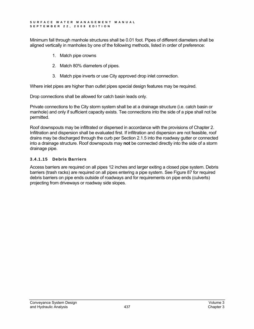
3.4.1.15 Debris Barriers
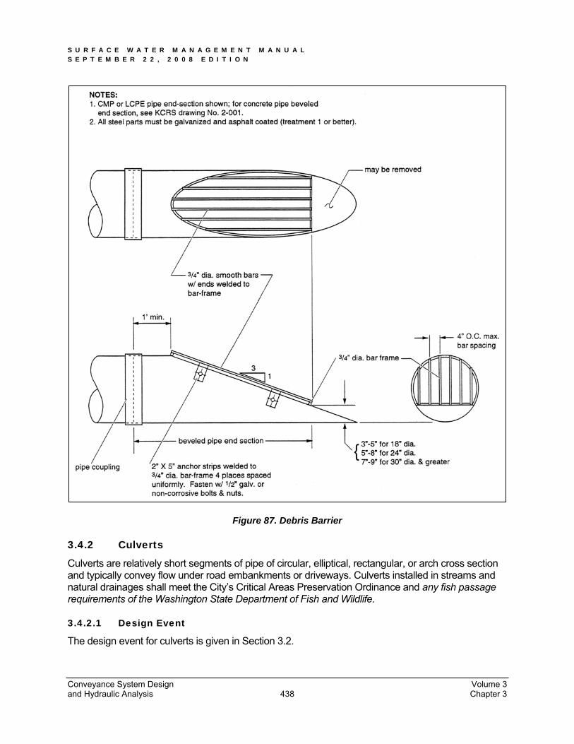
Access barriers are required on all pipes 12 inches and larger exiting a closed pipe system. Debris barriers (trash racks) are required on all pipes entering a pipe system. See Figure 87 for required debris barriers on pipe ends outside of roadways and for requirements on pipe ends (culverts) projecting from driveways or roadway side slopes.
Conveyance System Design Volume 3 and Hydraulic Analysis Chapter 3 437
S U R F A C E W A T E R M A N A G E M E N T M A N U A L S E P T E M B E R 2 2 , 2 0 0 8 E D I T I O N
Figure 87. Debris Barrier
3.4.2 Culverts
Culverts are relatively short segments of pipe of circular, elliptical, rectangular, or arch cross section and typically convey flow under road embankments or driveways. Culverts installed in streams and natural drainages shall meet the City’s Critical Areas Preservation Ordinance and any fish passage requirements of the Washington State Department of Fish and Wildlife.
3.4.2.1 Design Event
The design event for culverts is given in Section 3.2.
Conveyance System Design Volume 3 and Hydraulic Analysis Chapter 3 438
S U R F A C E W A T E R M A N A G E M E N T M A N U A L S E P T E M B E R 2 2 , 2 0 0 8 E D I T I O N
3.4.2.2 Design Flows
Design flows for sizing or assessing the capacity of culverts shall be determined using the hydrologic analysis methods described in this chapter.
Other single event models as described in Chapter 2 of this volume may be used to determine design flows. In addition, culverts shall not exceed the headwater requirements as established below:
3.4.2.3 Headwater
For culverts 18-inch diameter or less, the maximum allowable headwater elevation for the 100-year, 24-hour design storm (measured from the inlet invert) shall not exceed 2 times the pipe diameter or arch-culvert-rise.
For culverts larger than 18-inch diameter, the maximum allowable headwater elevation for the 100-year, 24-hour design storm (measured from the inlet invert) shall not exceed 1.5 times the pipe diameter or arch-culvert-rise.
The maximum headwater elevation at the 100-year, 24-hour design flow shall be below any road or parking lot subgrade.
3.4.2.4 Conveyance Capacity
Use the procedures presented in this section to analyze both inlet and outlet control conditions to determine which governs. Culvert capacity is then determined using graphical methods.
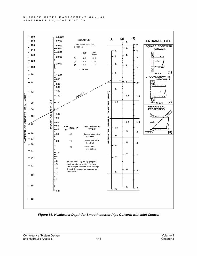
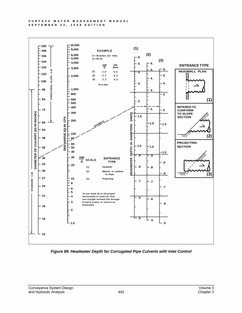
3.4.2.5 Inlet Control Analysis
Nomographs such as those provided in Figure 88 and Figure 89 can be used to determine the inlet control headwater depth at design flow for various types of culverts and inlet configurations. These and other nomographs can be found in the FHWA publication Hydraulic Design of Highway Culverts, HDS No. #5 (Report No. FHWA-NHI-01-020), September 2001; or the WSDOT Hydraulic Manual.
Also available in the FHWA publication are the design equations used to develop the inlet control nomographs. These equations are presented below.
For unsubmerged inlet conditions (defined by Q/AD0.5 < 3.5);
Form 1*: HW/D = Hc /D + K(Q/AD0.5)M - 0.5S** (equation 9)
Form 2*: HW/D = K(Q/AD0.5)M (equation 10)
For submerged inlet conditions (defined by Q/AD0.5> 4.0);
HW/D = c(Q/AD0.5)2 + Y – 0.5S** (equation 11)
Where HW = headwater depth above inlet invert (ft)
D = interior height of culvert barrel (ft)
Hc = specific head (ft) at critical depth (dc + Vc2/2g)
Conveyance System Design Volume 3 and Hydraulic Analysis Chapter 3 439
S U R F A C E W A T E R M A N A G E M E N T M A N U A L S E P T E M B E R 2 2 , 2 0 0 8 E D I T I O N
Q = flow (cfs)
A = full cross-sectional area of culvert barrel (sf)
S = culvert barrel slope (ft/ft)
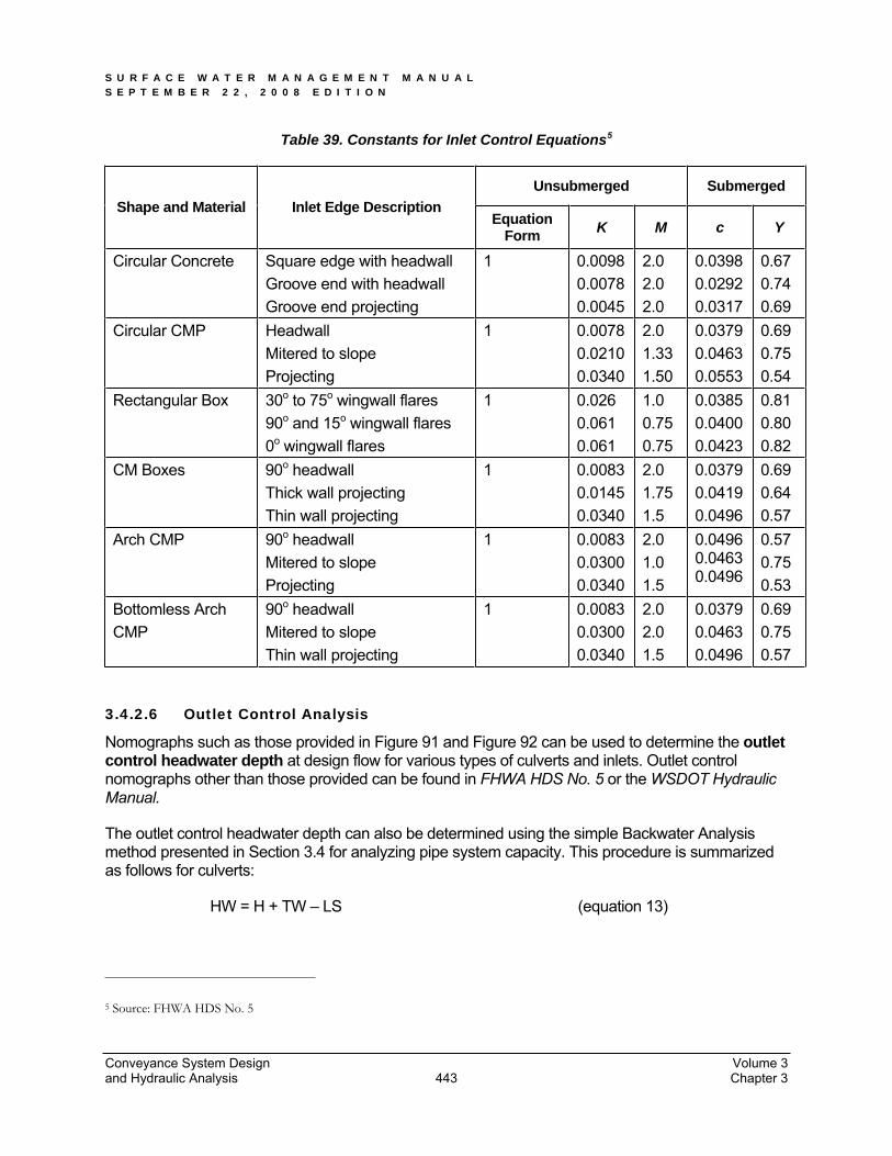
K,M,c,Y = constants from Table 39
The specified head Hc is determined by the following equation:
Hc = dc + Vc2/2g (equation 12)
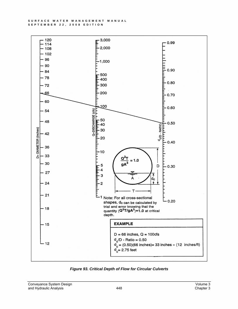
where dc = critical depth (ft); see Figure 93
Vc = flow velocity at critical depth (fps)
g = acceleration due to gravity (32.2 ft/sec2)
* The appropriate equation form for various inlet types is specified in Table 39
** For mitered inlets, use +0.7S instead of –0.5S.
NOTE: Between the unsubmerged and submerged conditions, there is a transition zone (3.5 < Q/AD0.5<4.0) for which there is only limited hydraulic study information. The transition zone is defined empirically by drawing a curve between and tangent to the curves defined by the unsubmerged and submerged equations. In most cases, the transition zone is short and the curve is easily constructed.
Conveyance System Design Volume 3 and Hydraulic Analysis Chapter 3 440
S U R F A C E W A T E R M A N A G E M E N T M A N U A L S E P T E M B E R 2 2 , 2 0 0 8 E D I T I O N
DIA
ME
TE
R
OF
C
ULV
ER
T
(D)
IN
INC
HE
S
ENTRANCETYPE
HWD
SCALE
(1)
(2)
(3)
Square edge with
Groove end with
Groove end
headwall
headwall
projecting
EXAMPLE
D = 42 inches (3.0 feet).Q = 120 cfs
HW*
*D in feet
HWD (feet)
(1)
(2)
(3)
2 . 5
2 . 1
2 . 2
8 . 8
7 . 4
7 . 7
EXAMPLE
DIS
CH
AR
GE
(Q
) IN
CF
S
HE
AD
WA
TE
R
DE
PT
H I
N D
IAM
ET
ER
S
(HW
/D)
To use scale (2) or (3) projecthorizontally to scale (1), thenuse straight inclined line throughD and Q scales, or reverse as illustrated.
1.0
2
3
4
56
8
10
20
30
40
5060
12
15
18
21
24
27
30
33
36
80
100
200
300
400
500600
800
1,000
42
48
54
60
2,000
3,000
4,000
5,0006,000
8,000
10,000
72
84
96
108
120
132
144
156
168
180
ENTRANCE TYPE
SQUARE EDGE WITHHEADWALL
GROOVE END WITH
GROOVE ENDPROJECTING
HEADWALL
PLAN
PLAN
(1) (2) (3)
.5.5 .5
.6.6 .6
.7.7 .7
.8.8 .8
.9
.9 .9
1.0
1.0 1.0
1.5
1.5 1.5
2.
2.
3.
3.3.
4.
4.4.
5.
2.
(3)
(2)
(1)
5.
5.6.
6.6.
New Design ManualFigure 4.3.1.B Headwater Depth for Smooth Interior Pipe Culverts with Inlet ControlRevised 12-2-97/Mdev
Figure 88. Headwater Depth for Smooth Interior Pipe Culverts with Inlet Control
Conveyance System Design Volume 3 and Hydraulic Analysis Chapter 3 441
S U R F A C E W A T E R M A N A G E M E N T M A N U A L S E P T E M B E R 2 2 , 2 0 0 8 E D I T I O N
STA
ND
AR
D C
.M.
DIA
ME
TE
R O
F C
ULV
ER
T (
D)
IN I
NC
HE
S
ST
RU
CT
UR
AL
P
LA
TE
C
.M.
ENTRANCETYPE
HWD SCALE
(1)
(2)
(3)
Headwall
Mitered to conformto slope
Projecting
EXAMPLE
D = 36 inches (3.0 feet).Q = 66 cfs
HW*
*D in feet
HWD (feet)
(1)
(2)
(3)
1 . 8
2 . 1
2 . 2
5 . 4
6 . 3
6 . 6
EXAMPLE
DIS
CH
AR
GE
(Q
) IN
CF
S
HE
AD
WA
TE
R D
EP
TH
IN
DIA
ME
TE
RS
(H
W/D
)
To use scale (2) or (3) projecthorizontally to scale (1), thenuse straight inclined line throughD and Q scales, or reverse as illustrated
1.0
2
3
4
56
8
10
20
30
40
5060
12
15
18
21
24
27
30
33
36
80
100
200
300
400
500600
800
1,000
42
48
54
60
2,000
3,000
4,000
5,0006,000
8,000
10,000
72
84
96
108
120
132
144
156
168
180
ENTRANCE TYPE
HEADWALL PLAN
MITERED TOCONFORMTO SLOPESECTION
PROJECTINGSECTION
(1)
(2)
(3)
.5.5
.5
.6 .6
.6
.7 .7
.7
.8 .8
.8
.9 .9
.9
1.0 1.0
1.0
1.5
1.5 1.5
2.
2.
3.
3.3.
4.
4.
4.
5.
2.
(3)
(2)
(1)
5.
5.
6.
6.
6.
New Design ManualFigure 4.3.1.C Headwater Depth for Corrugated Pipe Culverts with Inlet ControlRevised 11-24-97/Mdev
Figure 89. Headwater Depth for Corrugated Pipe Culverts with Inlet Control
Conveyance System Design Volume 3 and Hydraulic Analysis Chapter 3 442
S U R F A C E W A T E R M A N A G E M E N T M A N U A L S E P T E M B E R 2 2 , 2 0 0 8 E D I T I O N
Conveyance System Design Volume 3 and Hydraulic Analysis Chapter 3 443
Table 39. Constants for Inlet Control Equations5
Unsubmerged Submerged Shape and Material Inlet Edge Description
Equation Form K M c Y
Circular Concrete Square edge with headwall Groove end with headwall Groove end projecting
1 0.0098 0.0078 0.0045
2.02.02.0
0.0398 0.0292 0.0317
0.67 0.74 0.69
Circular CMP Headwall Mitered to slope Projecting
1 0.0078 0.0210 0.0340
2.01.33 1.50
0.0379 0.0463 0.0553
0.69 0.75 0.54
Rectangular Box 30o to 75o wingwall flares 90o and 15o wingwall flares 0o wingwall flares
1 0.026 0.061 0.061
1.00.75 0.75
0.0385 0.0400 0.0423
0.81 0.80 0.82
CM Boxes 90o headwall Thick wall projecting Thin wall projecting
1 0.0083 0.0145 0.0340
2.01.75 1.5
0.0379 0.0419 0.0496
0.69 0.64 0.57
Arch CMP 90o headwall Mitered to slope Projecting
1 0.0083 0.0300 0.0340
2.01.01.5
0.04960.04630.0496
0.57 0.75 0.53
Bottomless Arch CMP
90o headwall Mitered to slope Thin wall projecting
1 0.0083 0.0300 0.0340
2.02.01.5
0.0379 0.0463 0.0496
0.69 0.75 0.57
3.4.2.6 Outlet Control Analysis
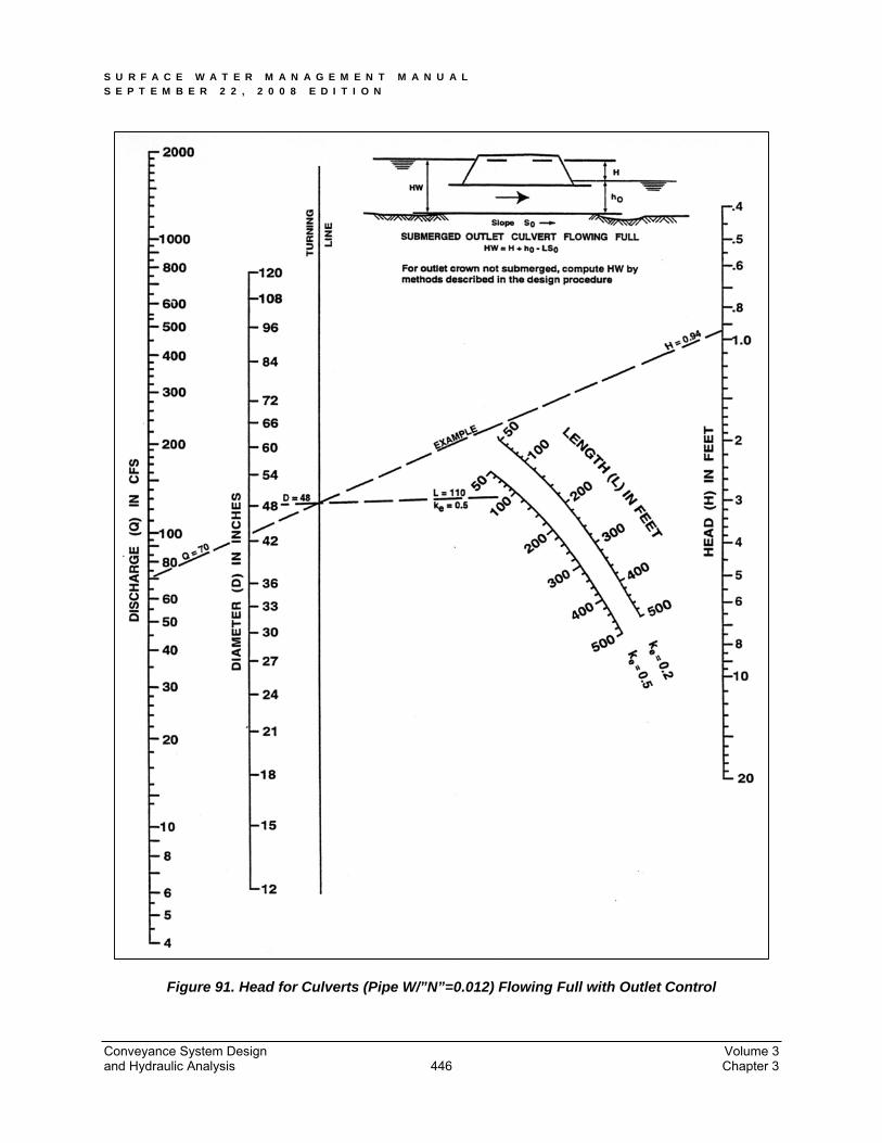
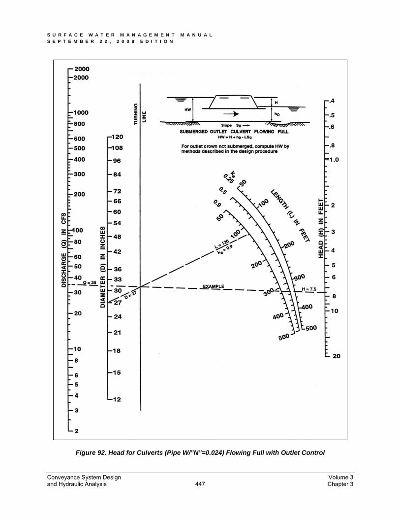
Nomographs such as those provided in Figure 91 and Figure 92 can be used to determine the outlet control headwater depth at design flow for various types of culverts and inlets. Outlet control nomographs other than those provided can be found in FHWA HDS No. 5 or the WSDOT Hydraulic Manual.
The outlet control headwater depth can also be determined using the simple Backwater Analysis method presented in Section 3.4 for analyzing pipe system capacity. This procedure is summarized as follows for culverts:
HW = H + TW – LS (equation 13)
5 Source: FHWA HDS No. 5
S U R F A C E W A T E R M A N A G E M E N T M A N U A L S E P T E M B E R 2 2 , 2 0 0 8 E D I T I O N
where H = Hf + He + Hex
Hf = friction loss (ft) = (V2n2L)/(2.22R1.33)
NOTE: If (Hf+TW-LS) < D, adjust Hf such that (Hf+TW-LS) = D. This will keep the analysis simple and still yield reasonable results (erring on the conservative side).
He = entrance head loss (ft) = Ke(V2/2g)
Hex = exit head loss (ft) = V2/2g
TW = tailwater depth above invert of culvert outlet (ft)
NOTE: If TW < (D+dc)/2, set TW = (D+dc)/2. This will keep the analysis simple and still yield reasonable results.
L = length of culvert (ft)
S = slope of culvert barrel (ft/ft)
D = interior height of culvert barrel (ft)
V = barrel velocity (fps)
n = Manning’s roughness coefficient from Table 35
R = hydraulic radius (ft)
Ke = entrance loss coefficient (from Table 40)
G = acceleration due to gravity (32.2 ft/sec2)
dc = critical depth (ft); see Figure 93
NOTE: The above procedure should not be used to develop stage/discharge curves for level pool routing purposes because its results are not precise for flow conditions where the hydraulic grade line falls significantly below the culvert crown (i.e., less than full flow conditions).
Conveyance System Design Volume 3 and Hydraulic Analysis Chapter 3 444
S U R F A C E W A T E R M A N A G E M E N T M A N U A L S E P T E M B E R 2 2 , 2 0 0 8 E D I T I O N
Figure 90. Junction Head Loss in Structures
Conveyance System Design Volume 3 and Hydraulic Analysis Chapter 3 445
S U R F A C E W A T E R M A N A G E M E N T M A N U A L S E P T E M B E R 2 2 , 2 0 0 8 E D I T I O N
Figure 91. Head for Culverts (Pipe W/”N”=0.012) Flowing Full with Outlet Control
Conveyance System Design Volume 3 and Hydraulic Analysis Chapter 3 446
S U R F A C E W A T E R M A N A G E M E N T M A N U A L S E P T E M B E R 2 2 , 2 0 0 8 E D I T I O N
Figure 92. Head for Culverts (Pipe W/”N”=0.024) Flowing Full with Outlet Control
Conveyance System Design Volume 3 and Hydraulic Analysis Chapter 3 447
S U R F A C E W A T E R M A N A G E M E N T M A N U A L S E P T E M B E R 2 2 , 2 0 0 8 E D I T I O N
Figure 93. Critical Depth of Flow for Circular Culverts
Conveyance System Design Volume 3 and Hydraulic Analysis Chapter 3 448
S U R F A C E W A T E R M A N A G E M E N T M A N U A L S E P T E M B E R 2 2 , 2 0 0 8 E D I T I O N
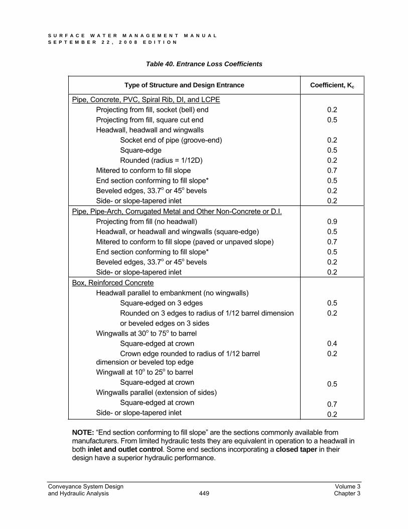
Table 40. Entrance Loss Coefficients
Type of Structure and Design Entrance Coefficient, Kc
Pipe, Concrete, PVC, Spiral Rib, DI, and LCPE Projecting from fill, socket (bell) end Projecting from fill, square cut end Headwall, headwall and wingwalls Socket end of pipe (groove-end) Square-edge Rounded (radius = 1/12D) Mitered to conform to fill slope End section conforming to fill slope* Beveled edges, 33.7o or 45o bevels Side- or slope-tapered inlet
0.20.5
0.20.50.20.70.50.20.2
Pipe, Pipe-Arch, Corrugated Metal and Other Non-Concrete or D.I. Projecting from fill (no headwall) Headwall, or headwall and wingwalls (square-edge) Mitered to conform to fill slope (paved or unpaved slope) End section conforming to fill slope* Beveled edges, 33.7o or 45o bevels Side- or slope-tapered inlet
0.90.50.70.50.20.2
Box, Reinforced Concrete Headwall parallel to embankment (no wingwalls) Square-edged on 3 edges Rounded on 3 edges to radius of 1/12 barrel dimension or beveled edges on 3 sides Wingwalls at 30o to 75o to barrel Square-edged at crown Crown edge rounded to radius of 1/12 barrel dimension or beveled top edge Wingwall at 10o to 25o to barrel Square-edged at crown Wingwalls parallel (extension of sides) Square-edged at crown Side- or slope-tapered inlet
0.50.2
0.40.2
0.5
0.70.2
NOTE: “End section conforming to fill slope” are the sections commonly available from manufacturers. From limited hydraulic tests they are equivalent in operation to a headwall in both inlet and outlet control. Some end sections incorporating a closed taper in their design have a superior hydraulic performance.
Conveyance System Design Volume 3 and Hydraulic Analysis Chapter 3 449

S U R F A C E W A T E R M A N A G E M E N T M A N U A L S E P T E M B E R 2 2 , 2 0 0 8 E D I T I O N
3.4.2.7 Inlets and Outlets
All inlets and outlets in or near roadway embankments must be flush with and conforming to the slope of the embankments.
For culverts 18-inch diameter and larger, the embankment around the culvert inlet shall be protected from erosion by rock lining or riprap as specified in Table 43,except the length shall extend at least 5 feet upstream of the culvert, and the height shall be at or above the design headwater elevation.
Inlet structures, such as concrete headwalls, may provide a more economical design by allowing the use of smaller entrance coefficients and, hence, smaller diameter culverts. When properly designed, they will also protect the embankment from erosion and eliminate the need for rock lining.
In order to maintain the stability of roadway embankments, concrete headwalls, wingwalls, or tapered inlets and outlets may be required if right-of-way or easement constraints prohibit the culvert from extending to the toe of the embankment slopes. All inlet structures or headwalls installed in or near roadway embankments must be flush with and conforming to the slope of the embankment.
Debris barriers (trash racks) are required on the inlets of all culverts that are over 60 feet in length and are 12 to 36 inches in diameter. This requirement also applies to the inlets of pipe systems. See Figure 87 for a debris barrier detail. Exceptions are culverts on Type 1 or 2 streams.
For culverts 18-inch diameter and larger, the receiving channel of the outlet shall be protected from erosion by rock lining specified in Table 43, except the height shall be one foot above maximum tailwater elevation or one foot above the crown per Figure 101, whichever is higher.
Conveyance System Design Volume 3 and Hydraulic Analysis Chapter 3 450
S U R F A C E W A T E R M A N A G E M E N T M A N U A L S E P T E M B E R 2 2 , 2 0 0 8 E D I T I O N
3.4.3 Open Channels
This section presents the methods, criteria, and details for hydraulic analysis and design of open channels.
3.4.3.1 Natural Channels
Natural channels are defined as those that have occurred naturally due to the flow of surface waters, or those that, although originally constructed by human activity, have taken on the appearance of a natural channel including a stable route and biological community. They may vary hydraulically along each channel reach and should be left in their natural condition, wherever feasible or required, in order to maintain natural hydrologic functions and wildlife habitat benefits from established vegetation.
3.4.3.2 Constructed Channels
Constructed channels are those constructed or maintained by human activity and include bank stabilization of natural channels. Constructed channels shall be either vegetation-lined, rock lined, or lined with appropriately bioengineered vegetation.
Vegetation-lined channels are the most desirable of the constructed channels when properly designed and constructed. The vegetation stabilizes the slopes of the channel, controls erosion of the channel surface, and removes pollutants. The channel storage, low velocities, water quality benefits, and greenbelt multiple-use benefits create significant advantages over other constructed channels. The presence of vegetation in channels creates turbulence, which results in loss of energy and increased flow retardation; therefore, the design engineer must consider sediment deposition and scour, as well as flow capacity, when designing the channel.
Rock-lined channels are necessary where a vegetative lining will not provide adequate protection from erosive velocities they may be constructed with riprap, gabions, or slope mattress linings. The rock lining increases the turbulence, resulting in a loss of energy and increased flow retardation. Rock lining also permits a higher design velocity and therefore a steeper design slope than in grass-lined channels. Rock linings are also used for erosion control at culvert and storm drain outlets, sharp channel bends, channel confluences, and locally steepened channel sections.
Bioengineered vegetation lining is a desirable alternative to the conventional methods of rock armoring. Soil bioengineering is a highly specialized science that uses living plants and plant parts to stabilize eroded or damaged land. Properly bioengineering systems are capable of providing a measure of immediate soil protection and mechanical reinforcement. As the plants grow they produce vegetative protective cover and a root reinforcing matrix in the soil mantle. This root reinforcement serves several purposes:
a. The developed anchor roots provide both shear and tensile strength to the soil, thereby providing protection from the frictional shear and tensile velocity components to the soil mantle during the time when flows are receding and pore pressure is high in the saturated bank.
Conveyance System Design Volume 3 and Hydraulic Analysis Chapter 3 451
S U R F A C E W A T E R M A N A G E M E N T M A N U A L S E P T E M B E R 2 2 , 2 0 0 8 E D I T I O N
b. The root mat provides a living filter in the soil mantle that allows for the natural release of water after the high flows have receded.
c. The combined root system exhibits active friction transfer along the length of the living roots. This consolidates soil particles in the bank and serves to protect the soil structure from collapsing and the stabilization measures from failing.
3.4.3.3 Design Flows
Design flows for sizing or assessing the capacity of open channels shall be determined using the hydrologic analysis methods described in this chapter. Single event models as described in Chapter 2 of this volume may be used to determine design flows. In addition, open channel shall meet the following:
Open channels shall be designed to provide required conveyance capacity while minimizing erosion and allowing for aesthetics, habitat preservation, and enhancement.
An access easement for maintenance is required along all constructed channels located on private property. Required easement widths and building setback lines vary with channel top width.
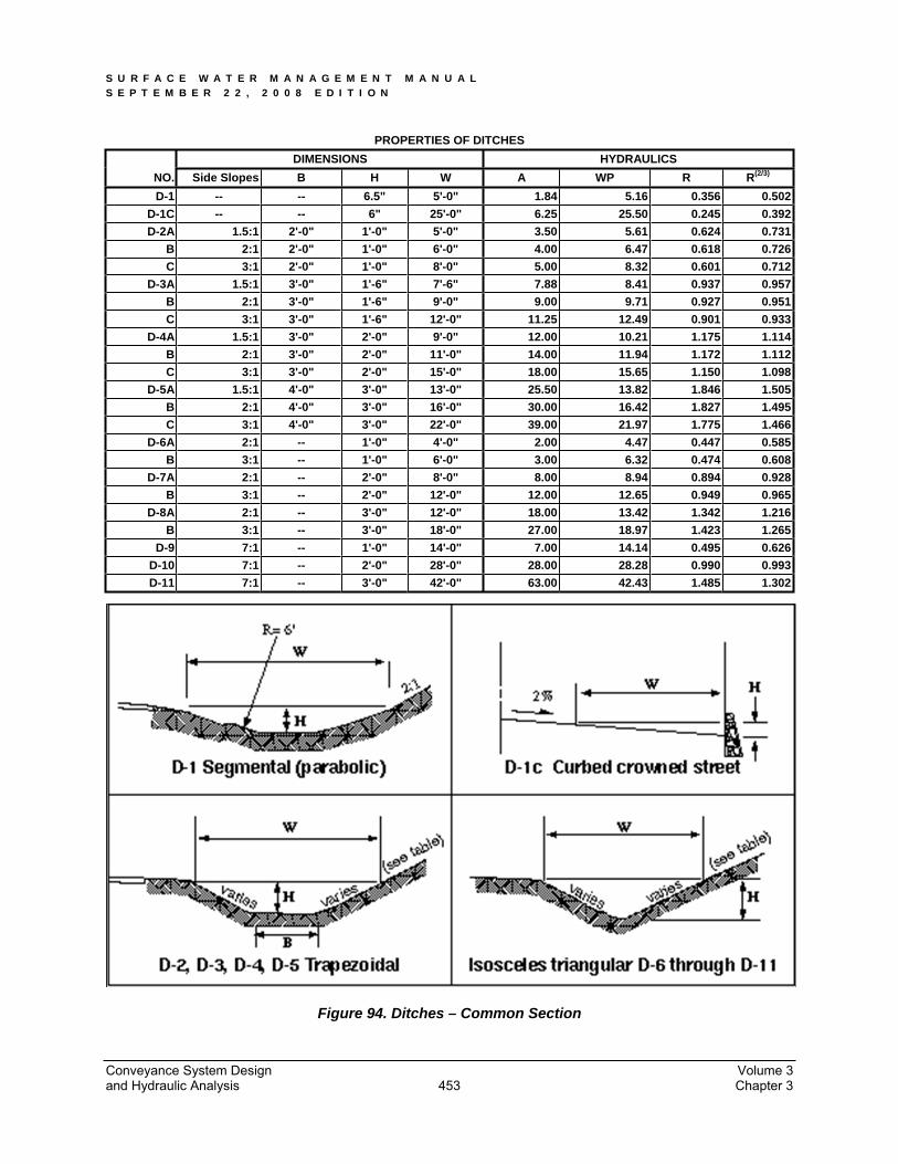
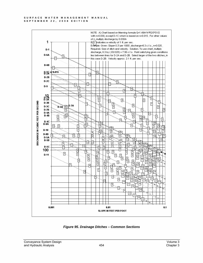
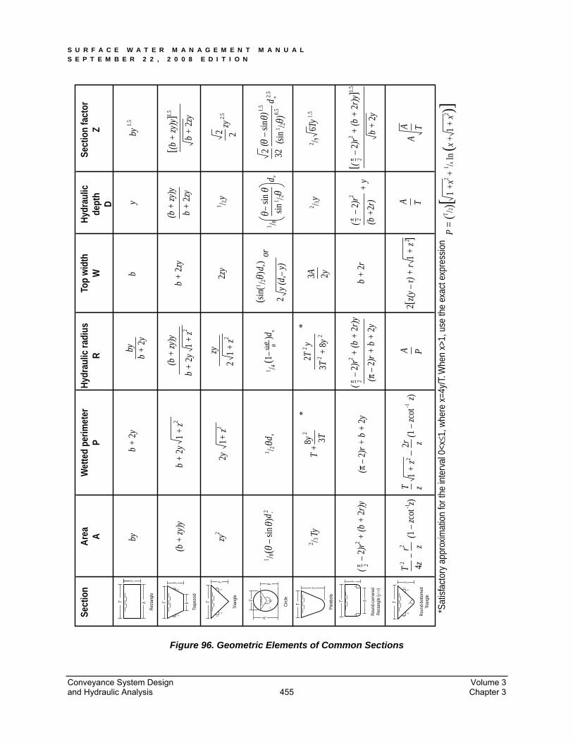
Channel cross-section geometry shall be trapezoidal, triangular, parabolic, or segmental as shown in Figure 94 through Figure 96. Side slopes shall be no steeper than 3:1 for vegetation-lined channels and 2:1 for rock-lined channels.
Vegetation-lined channels shall have bottom slope gradients of 6% or less and a maximum velocity at design flow of 5 fps (see Table 42).
Rock-lined channels or bank stabilization of natural channels shall be used when design flow velocities exceed 5 feet per second. Rock stabilization shall be in accordance with Table 42 or stabilized with bioengineering methods as described above in “Constructed Channels.”
Conveyance System Design Volume 3 and Hydraulic Analysis Chapter 3 452
S U R F A C E W A T E R M A N A G E M E N T M A N U A L S E P T E M B E R 2 2 , 2 0 0 8 E D I T I O N
PROPERTIES OF DITCHES DIMENSIONS HYDRAULICS
NO. Side Slopes B H W A WP R R(2/3)
D-1 -- -- 6.5" 5'-0" 1.84 5.16 0.356 0.502 D-1C -- -- 6" 25'-0" 6.25 25.50 0.245 0.392D-2A 1.5:1 2'-0" 1'-0" 5'-0" 3.50 5.61 0.624 0.731
B 2:1 2'-0" 1'-0" 6'-0" 4.00 6.47 0.618 0.726C 3:1 2'-0" 1'-0" 8'-0" 5.00 8.32 0.601 0.712
D-3A 1.5:1 3'-0" 1'-6" 7'-6" 7.88 8.41 0.937 0.957B 2:1 3'-0" 1'-6" 9'-0" 9.00 9.71 0.927 0.951C 3:1 3'-0" 1'-6" 12'-0" 11.25 12.49 0.901 0.933
D-4A 1.5:1 3'-0" 2'-0" 9'-0" 12.00 10.21 1.175 1.114B 2:1 3'-0" 2'-0" 11'-0" 14.00 11.94 1.172 1.112C 3:1 3'-0" 2'-0" 15'-0" 18.00 15.65 1.150 1.098
D-5A 1.5:1 4'-0" 3'-0" 13'-0" 25.50 13.82 1.846 1.505B 2:1 4'-0" 3'-0" 16'-0" 30.00 16.42 1.827 1.495C 3:1 4'-0" 3'-0" 22'-0" 39.00 21.97 1.775 1.466
D-6A 2:1 -- 1'-0" 4'-0" 2.00 4.47 0.447 0.585B 3:1 -- 1'-0" 6'-0" 3.00 6.32 0.474 0.608
D-7A 2:1 -- 2'-0" 8'-0" 8.00 8.94 0.894 0.928B 3:1 -- 2'-0" 12'-0" 12.00 12.65 0.949 0.965
D-8A 2:1 -- 3'-0" 12'-0" 18.00 13.42 1.342 1.216B 3:1 -- 3'-0" 18'-0" 27.00 18.97 1.423 1.265
D-9 7:1 -- 1'-0" 14'-0" 7.00 14.14 0.495 0.626D-10 7:1 -- 2'-0" 28'-0" 28.00 28.28 0.990 0.993D-11 7:1 -- 3'-0" 42'-0" 63.00 42.43 1.485 1.302
Figure 94. Ditches – Common Section
Conveyance System Design Volume 3 and Hydraulic Analysis Chapter 3 453
S U R F A C E W A T E R M A N A G E M E N T M A N U A L S E P T E M B E R 2 2 , 2 0 0 8 E D I T I O N
Figure 95. Drainage Ditches – Common Sections
Conveyance System Design Volume 3 and Hydraulic Analysis Chapter 3 454
S U R F A C E W A T E R M A N A G E M E N T M A N U A L S E P T E M B E R 2 2 , 2 0 0 8 E D I T I O N
Sect
ion
Are
aA
Wet
ted
perim
eter
PH
ydra
ulic
radi
usR
Top
wid
thW
Hyd
raul
icde
pth
D
Sect
ion
fact
orZ by
1.5
yb
byb
+ 2
yby
b +
2y
b +
2zy
2zy
or
zyy
d
(b +
zy)y
b +
2y
b +
2y
1 +
z2
zy2
zy2y
1+ z2
21
+ z2
(b +
zy)y
1 +
z2b
+ 2
zy
(b +
zy)y
1 /2
1 /81 /2
[(b +
zy)y
]b
+ 2
zy
1.5
1.5
2.5
2.5
1.5
1.50.
5
2
2
6Ty
32
2
3A 2y
2
0–si
nsi
n0 0
˚d
1 /2
0–
sin
sin
0 0˚
( (
) )
d1 /20
(sin
(˚
˚))
y (d
– y
)
y2 /3
P =
(T /2)[
2 /9
0(1
–
)d
1 /4
2 /3
sin
˚0
d 0˚
1 /22
1 /80
(–
sin
)d
TyT
+
(π–
2)r +
b +
2y
1 +
z
(–
2)r2 +
(b +
2r)
y
(1–
zcot
z)
3T+
8y
˚0
2
4zz
2*
y
3T
2T8y
2
2
*
2
(–
2)r2 +
(b +
2r)
yb
+ 2
r+
y2 (π
–2)
r + b
+ 2
y
(–
2)r2
2 (b +
2r)
[(–
2)r2 +
(b +
2r)
y]
1 +
x2 + 1 /x
ln (x
+ 1
+ x
2 )]
2
b +
2y
T2
-1r2
(1–
zcot
z)z
zT
2-1
2rA P
A T2
2[z(
y–
r) +
r1
+ z
]A
AT
*Sat
isfa
ctor
y ap
prox
imat
ion
for t
he in
terv
al 0
<x≤1
, whe
re x
=4y/
T. W
hen
x>1,
use
the
exac
t exp
ress
ion
ππ
π
T
y
Rec
tang
le
b T b
Trap
ezoi
d
y1
z1
z
1z
1z
Tria
ngle
T
y
0
d ˚y
T
T
Para
bola
y
Circ
le
rr
bT
y
r
Rou
nd-c
orne
red
Rec
tang
le (y
>r)
T
y1
z1
z
Rou
nd-b
otto
med
Tria
ngle
π
Figure 96. Geometric Elements of Common Sections
Conveyance System Design Volume 3 and Hydraulic Analysis Chapter 3 455
S U R F A C E W A T E R M A N A G E M E N T M A N U A L S E P T E M B E R 2 2 , 2 0 0 8 E D I T I O N
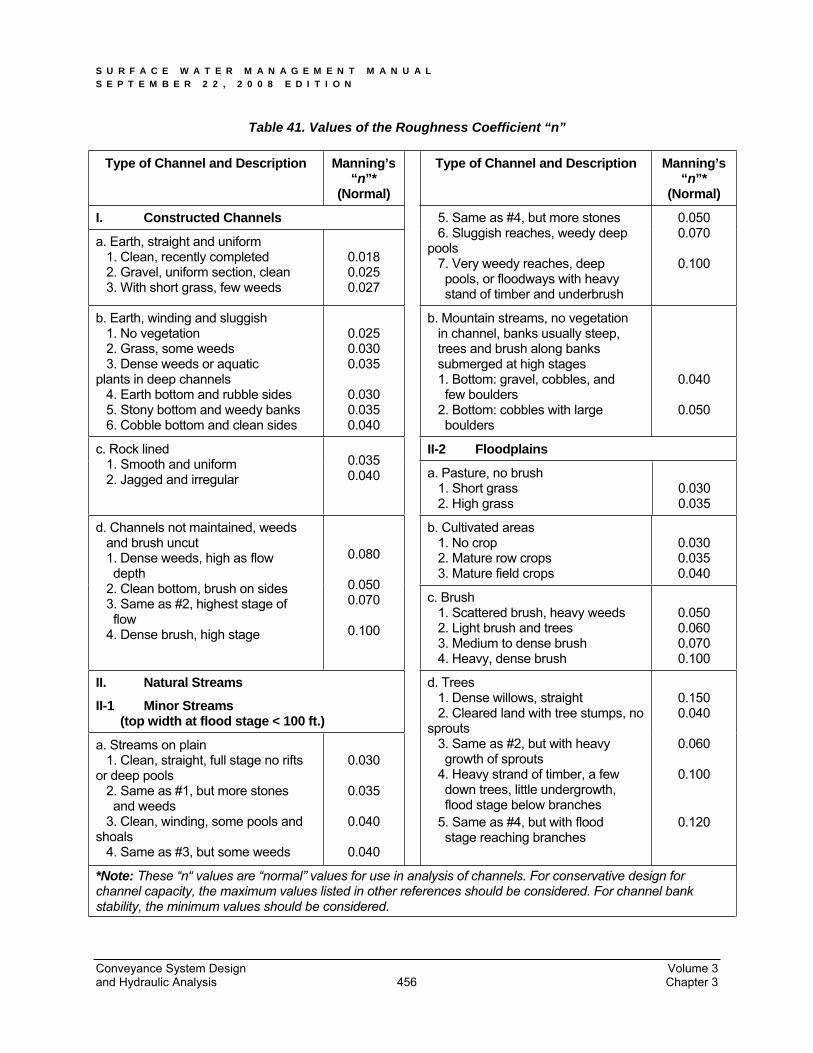
Table 41. Values of the Roughness Coefficient “n”
Type of Channel and Description Manning’s “n”*
(Normal)
Type of Channel and Description Manning’s “n”*
(Normal)
I. Constructed Channels
a. Earth, straight and uniform 1. Clean, recently completed 2. Gravel, uniform section, clean 3. With short grass, few weeds
0.018 0.025 0.027
5. Same as #4, but more stones 6. Sluggish reaches, weedy deep pools 7. Very weedy reaches, deep pools, or floodways with heavy stand of timber and underbrush
0.050 0.070
0.100
b. Earth, winding and sluggish 1. No vegetation 2. Grass, some weeds 3. Dense weeds or aquatic plants in deep channels 4. Earth bottom and rubble sides 5. Stony bottom and weedy banks 6. Cobble bottom and clean sides
0.025 0.030 0.035
0.030 0.035 0.040
b. Mountain streams, no vegetation in channel, banks usually steep, trees and brush along banks submerged at high stages 1. Bottom: gravel, cobbles, and few boulders 2. Bottom: cobbles with large boulders
0.040
0.050
II-2 Floodplains c. Rock lined 1. Smooth and uniform 2. Jagged and irregular
0.035 0.040 a. Pasture, no brush
1. Short grass 2. High grass
0.030 0.035
b. Cultivated areas 1. No crop 2. Mature row crops 3. Mature field crops
0.030 0.035 0.040
d. Channels not maintained, weeds and brush uncut 1. Dense weeds, high as flow depth 2. Clean bottom, brush on sides 3. Same as #2, highest stage of flow 4. Dense brush, high stage
0.080
0.050 0.070
0.100
c. Brush 1. Scattered brush, heavy weeds 2. Light brush and trees 3. Medium to dense brush 4. Heavy, dense brush
0.050 0.060 0.070 0.100
II. Natural Streams
II-1 Minor Streams (top width at flood stage < 100 ft.)
a. Streams on plain 1. Clean, straight, full stage no rifts or deep pools 2. Same as #1, but more stones and weeds 3. Clean, winding, some pools and shoals 4. Same as #3, but some weeds
0.030
0.035
0.040
0.040
d. Trees 1. Dense willows, straight 2. Cleared land with tree stumps, no sprouts 3. Same as #2, but with heavy growth of sprouts 4. Heavy strand of timber, a few down trees, little undergrowth, flood stage below branches 5. Same as #4, but with flood stage reaching branches
0.150 0.040
0.060
0.100
0.120
*Note: These “n“ values are “normal” values for use in analysis of channels. For conservative design for channel capacity, the maximum values listed in other references should be considered. For channel bank stability, the minimum values should be considered.
Conveyance System Design Volume 3 and Hydraulic Analysis Chapter 3 456
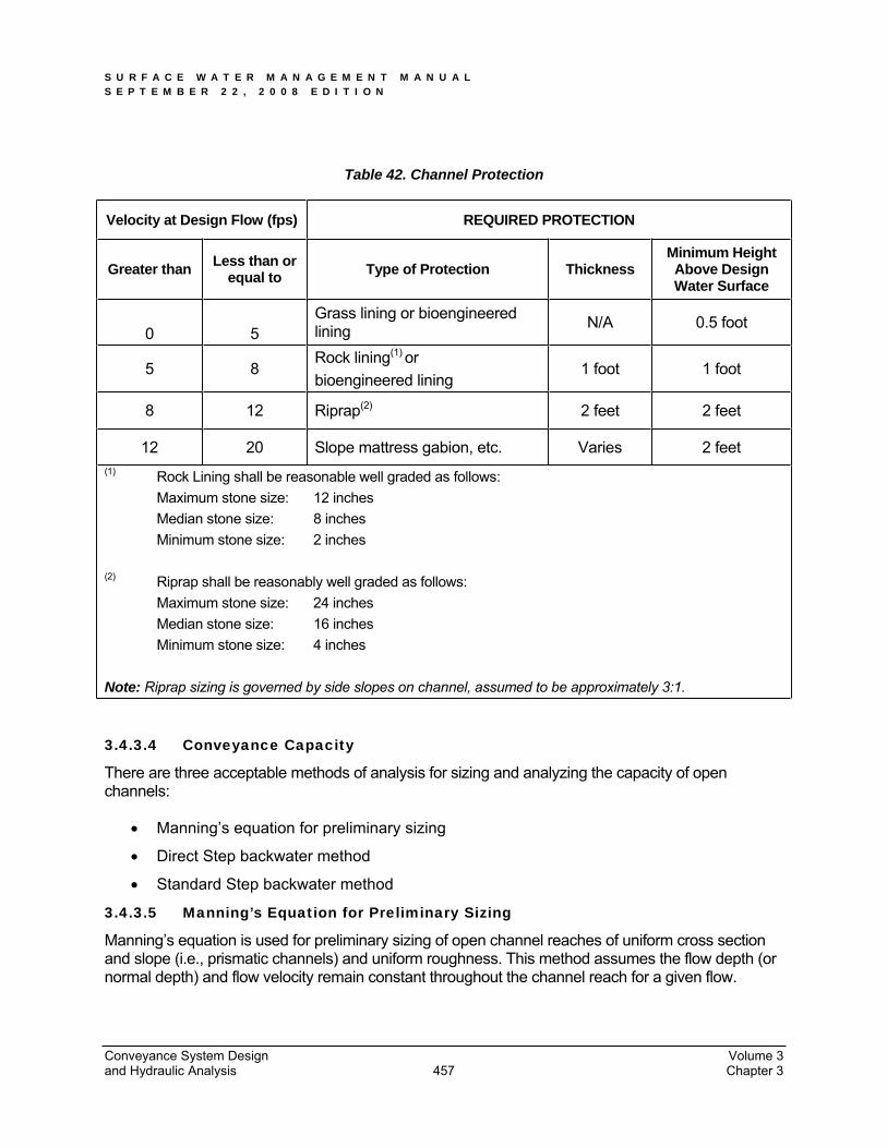
S U R F A C E W A T E R M A N A G E M E N T M A N U A L S E P T E M B E R 2 2 , 2 0 0 8 E D I T I O N
Table 42. Channel Protection
Velocity at Design Flow (fps) REQUIRED PROTECTION
Greater than Less than or equal to Type of Protection Thickness
Minimum Height Above Design Water Surface
0 5Grass lining or bioengineered lining N/A 0.5 foot
5 8Rock lining(1) orbioengineered lining
1 foot 1 foot
8 12 Riprap(2) 2 feet 2 feet
12 20 Slope mattress gabion, etc. Varies 2 feet (1) Rock Lining shall be reasonable well graded as follows: Maximum stone size: 12 inches Median stone size: 8 inches Minimum stone size: 2 inches
(2) Riprap shall be reasonably well graded as follows: Maximum stone size: 24 inches Median stone size: 16 inches Minimum stone size: 4 inches
Note: Riprap sizing is governed by side slopes on channel, assumed to be approximately 3:1.
3.4.3.4 Conveyance Capacity
There are three acceptable methods of analysis for sizing and analyzing the capacity of open channels:
Manning’s equation for preliminary sizing
Direct Step backwater method
Standard Step backwater method
3.4.3.5 Manning’s Equation for Preliminary Sizing
Manning’s equation is used for preliminary sizing of open channel reaches of uniform cross section and slope (i.e., prismatic channels) and uniform roughness. This method assumes the flow depth (or normal depth) and flow velocity remain constant throughout the channel reach for a given flow.
Conveyance System Design Volume 3 and Hydraulic Analysis Chapter 3 457
S U R F A C E W A T E R M A N A G E M E N T M A N U A L S E P T E M B E R 2 2 , 2 0 0 8 E D I T I O N
The charts in Figure 94 and Figure 95 can be used to obtain graphic solutions of Manning’s equation for common ditch sections. For conditions outside the range of these charts or for more precise results, Manning’s equation can be solved directly from its classic forms shown in Equations 7 and 8 Section 3.4.1.2.
Table 41 provides a reference for selecting the appropriate “n” values for open channels. A number of engineering reference books, such as Open-Channel Hydraulics by V.T. Chow, may also be used as guides to select “n” values. Figure 96 contains the geometric elements of common channel sections useful in determining area A, wetted perimeter WP, and hydraulic radius (R=A/WP).
If flow restrictions raise the water level above normal depth within a given channel reach, a backwater condition (or non-uniform flow) is said to exist. This condition can result from flow restrictions created by a downstream culvert, bridge, dam, pond, lake, etc., and even a downstream channel reach having a higher normal flow depth. If backwater conditions are found to exist for the design flow, a backwater profile must be computed to verify that the channel’s capacity is still adequate as designed. The Direct Step or Standard Step backwater methods presented in this section can be used for this purpose.
3.4.3.6 Direct Step Backwater Method
The Direct Step Backwater Method can be used to compute backwater profiles on prismatic channel reaches (i.e. reaches having uniform cross section and slope) where a backwater condition or restriction to normal flow is known to exist. The method can be applied to a series of prismatic channel reaches in succession beginning at the downstream end of the channel and computing the profile upstream.
Calculating the coordinates of the water surface profile using the method is an iterative process achieved by choosing a range of flow depths, beginning at the downstream end, and proceeding incrementally up to the point of interest or to the point of normal flow depth. This is best accomplished by the use of a table (see Figure 98) or computer programs.
Conveyance System Design Volume 3 and Hydraulic Analysis Chapter 3 458

S U R F A C E W A T E R M A N A G E M E N T M A N U A L S E P T E M B E R 2 2 , 2 0 0 8 E D I T I O N
Figure 97. Open Channel Flow Profile Computation
Conveyance System Design Volume 3 and Hydraulic Analysis Chapter 3 459
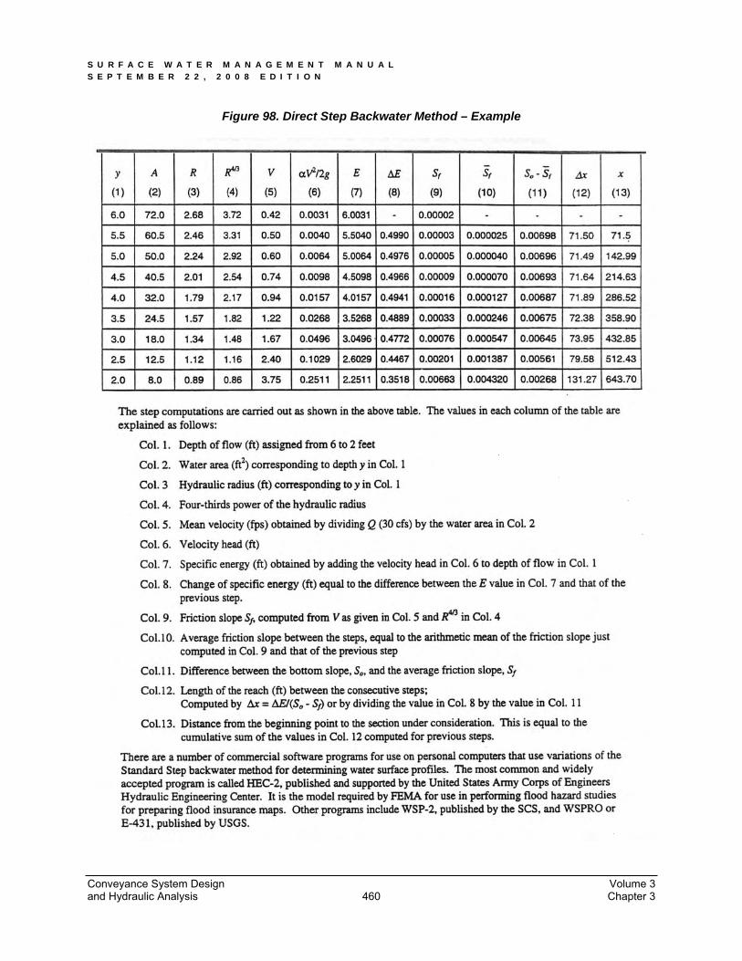
S U R F A C E W A T E R M A N A G E M E N T M A N U A L S E P T E M B E R 2 2 , 2 0 0 8 E D I T I O N
Figure 98. Direct Step Backwater Method – Example
Conveyance System Design Volume 3 and Hydraulic Analysis Chapter 3 460
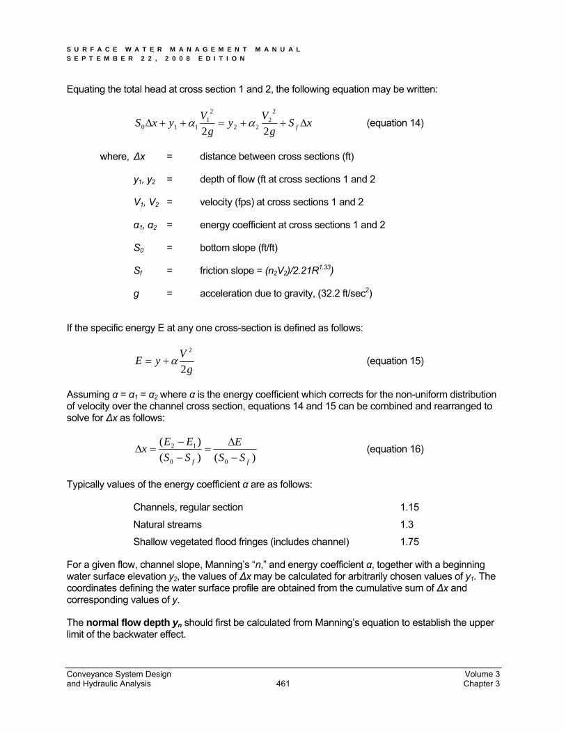
S U R F A C E W A T E R M A N A G E M E N T M A N U A L S E P T E M B E R 2 2 , 2 0 0 8 E D I T I O N
Equating the total head at cross section 1 and 2, the following equation may be written:
xSg
Vyg
VyxS f22
22
22
21
110 (equation 14)
where, x = distance between cross sections (ft)
y1, y2 = depth of flow (ft at cross sections 1 and 2
V1, V2 = velocity (fps) at cross sections 1 and 2
1, 2 = energy coefficient at cross sections 1 and 2
S0 = bottom slope (ft/ft)
Sf = friction slope = (n2V2)/2.21R1.33)
g = acceleration due to gravity, (32.2 ft/sec2)
If the specific energy E at any one cross-section is defined as follows:
gVyE2
2
(equation 15)
Assuming = 1 = 2 where is the energy coefficient which corrects for the non-uniform distribution of velocity over the channel cross section, equations 14 and 15 can be combined and rearranged to solve for x as follows:
)()()(
00
12
ff SSE
SSEEx (equation 16)
Typically values of the energy coefficient are as follows:
Channels, regular section 1.15
Natural streams 1.3
Shallow vegetated flood fringes (includes channel) 1.75
For a given flow, channel slope, Manning’s “n,” and energy coefficient , together with a beginning water surface elevation y2, the values of x may be calculated for arbitrarily chosen values of y1. The coordinates defining the water surface profile are obtained from the cumulative sum of x and corresponding values of y.
The normal flow depth yn should first be calculated from Manning’s equation to establish the upper limit of the backwater effect.
Conveyance System Design Volume 3 and Hydraulic Analysis Chapter 3 461
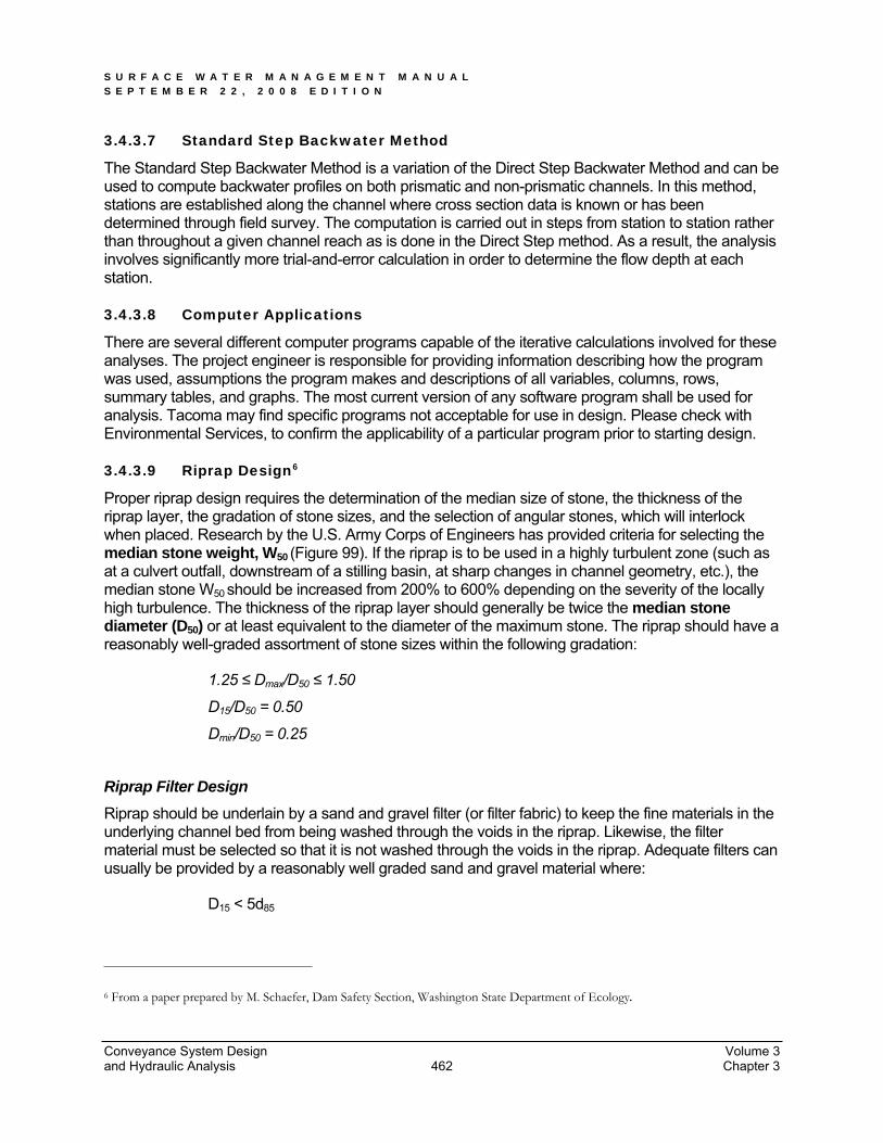
S U R F A C E W A T E R M A N A G E M E N T M A N U A L S E P T E M B E R 2 2 , 2 0 0 8 E D I T I O N
Conveyance System Design Volume 3 and Hydraulic Analysis Chapter 3 462
3.4.3.7 Standard Step Backwater Method
The Standard Step Backwater Method is a variation of the Direct Step Backwater Method and can be used to compute backwater profiles on both prismatic and non-prismatic channels. In this method, stations are established along the channel where cross section data is known or has been determined through field survey. The computation is carried out in steps from station to station rather than throughout a given channel reach as is done in the Direct Step method. As a result, the analysis involves significantly more trial-and-error calculation in order to determine the flow depth at each station.
3.4.3.8 Computer Applications
There are several different computer programs capable of the iterative calculations involved for these analyses. The project engineer is responsible for providing information describing how the program was used, assumptions the program makes and descriptions of all variables, columns, rows, summary tables, and graphs. The most current version of any software program shall be used for analysis. Tacoma may find specific programs not acceptable for use in design. Please check with Environmental Services, to confirm the applicability of a particular program prior to starting design.
3.4.3.9 Riprap Design6
Proper riprap design requires the determination of the median size of stone, the thickness of the riprap layer, the gradation of stone sizes, and the selection of angular stones, which will interlock when placed. Research by the U.S. Army Corps of Engineers has provided criteria for selecting the median stone weight, W50 (Figure 99). If the riprap is to be used in a highly turbulent zone (such as at a culvert outfall, downstream of a stilling basin, at sharp changes in channel geometry, etc.), the median stone W50 should be increased from 200% to 600% depending on the severity of the locally high turbulence. The thickness of the riprap layer should generally be twice the median stone diameter (D50) or at least equivalent to the diameter of the maximum stone. The riprap should have a reasonably well-graded assortment of stone sizes within the following gradation:
1.25 Dmax/D50 1.50
D15/D50 = 0.50
Dmin/D50 = 0.25
Riprap Filter Design Riprap should be underlain by a sand and gravel filter (or filter fabric) to keep the fine materials in the underlying channel bed from being washed through the voids in the riprap. Likewise, the filter material must be selected so that it is not washed through the voids in the riprap. Adequate filters can usually be provided by a reasonably well graded sand and gravel material where:
D15 < 5d85
6 From a paper prepared by M. Schaefer, Dam Safety Section, Washington State Department of Ecology.

S U R F A C E W A T E R M A N A G E M E N T M A N U A L S E P T E M B E R 2 2 , 2 0 0 8 E D I T I O N
The variable d85 refers to the sieve opening through which 85% of the material being protected will pass, and D15 has the same interpretation for the filter material. A filter material with a D50 of 0.5 mm will protect any finer material including clay. Where very large riprap is used, it is sometimes necessary to use two filter layers between the material being protected and the riprap.
Example:
What embedded riprap design should be used to protect a streambank at a level culvert outfall where the outfall velocities in the vicinity of the downstream toe are expected to be about 8 fps.
From Figure 99, W50 = 6.5 lbs, but since the downstream area below the outfall will be subjected to severe turbulence, increase W50 by 400% so that:
W50 = 26 lbs, D50 = 8.0 inches
The gradation of the riprap is shown in Figure 100, and the minimum thickness would be 1 foot (from Table 42); however, 16 inches to 24 inches of riprap thickness would provide some additional insurance that the riprap will function properly in this highly turbulent area.
Figure 100 shows that the gradation curve for ASTM C33, size number 57 coarse aggregate (used in concrete mixes), would meet the filter criteria. Applying the filter criteria to the coarse aggregate demonstrates that any underlying material whose gradation was coarser than that of concrete sand would be protected.
For additional information and procedures for specifying filters for riprap, refer to the Army Corps of Engineers Manual EM 1110-2-1601 (1970), Hydraulic Design of Flood Control Channels, Paragraph 14, “Riprap Protection.”
Conveyance System Design Volume 3 and Hydraulic Analysis Chapter 3 463
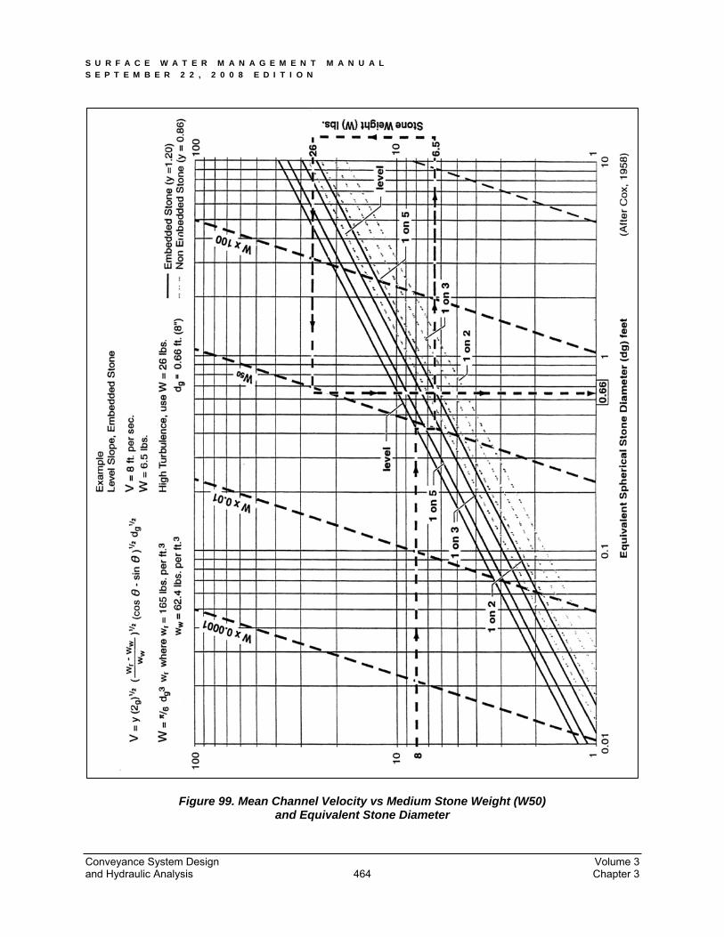
S U R F A C E W A T E R M A N A G E M E N T M A N U A L S E P T E M B E R 2 2 , 2 0 0 8 E D I T I O N
Figure 99. Mean Channel Velocity vs Medium Stone Weight (W50) and Equivalent Stone Diameter
Conveyance System Design Volume 3 and Hydraulic Analysis Chapter 3 464

S U R F A C E W A T E R M A N A G E M E N T M A N U A L S E P T E M B E R 2 2 , 2 0 0 8 E D I T I O N
Figure 100. Riprap Gradation Curve
Conveyance System Design Volume 3 and Hydraulic Analysis Chapter 3 465
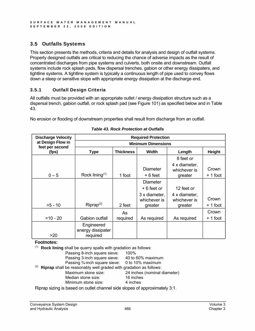
S U R F A C E W A T E R M A N A G E M E N T M A N U A L S E P T E M B E R 2 2 , 2 0 0 8 E D I T I O N
3.5 Outfalls Systems This section presents the methods, criteria and details for analysis and design of outfall systems. Properly designed outfalls are critical to reducing the chance of adverse impacts as the result of concentrated discharges from pipe systems and culverts, both onsite and downstream. Outfall systems include rock splash pads, flow dispersal trenches, gabion or other energy dissipaters, and tightline systems. A tightline system is typically a continuous length of pipe used to convey flows down a steep or sensitive slope with appropriate energy dissipation at the discharge end.
3.5.1 Outfall Design Criteria
All outfalls must be provided with an appropriate outlet / energy dissipation structure such as a dispersal trench, gabion outfall, or rock splash pad (see Figure 101) as specified below and in Table43.
No erosion or flooding of downstream properties shall result from discharge from an outfall.
Table 43. Rock Protection at Outfalls
Required Protection Minimum Dimensions
Discharge Velocity at Design Flow in feet per second
(fps) Type Thickness Width Length Height
0 – 5 Rock lining(1) 1 foot Diameter + 6 feet
8 feet or4 x diameter, whichever is
greater Crown + 1 foot
>5 - 10 Riprap(2) 2 feet
Diameter + 6 feet or
3 x diameter, whichever is
greater
12 feet or4 x diameter, whichever is
greater Crown + 1 foot
>10 - 20 Gabion outfall As
required As required As required Crown + 1 foot
>20
Engineered energy dissipater
required Footnotes: (1) Rock lining shall be quarry spalls with gradation as follows:
Passing 8-inch square sieve: 100% Passing 3-inch square sieve: 40 to 60% maximum Passing ¾-inch square sieve: 0 to 10% maximum
(2) Riprap shall be reasonably well graded with gradation as follows: Maximum stone size: 24 inches (nominal diameter) Median stone size: 16 inches Minimum stone size: 4 inches
Riprap sizing is based on outlet channel side slopes of approximately 3:1.
Conveyance System Design Volume 3 and Hydraulic Analysis Chapter 3 466
S U R F A C E W A T E R M A N A G E M E N T M A N U A L S E P T E M B E R 2 2 , 2 0 0 8 E D I T I O N
3.5.1.1 Energy dissipation
For freshwater outfalls with a design velocity greater than 10 fps, a gabion dissipater or engineered energy dissipater may be required. The gabion outfall detail shown in Figure 104 is illustrative only. A design engineered to specific site conditions must be developed.
In marine waters, rock splash pads and gabion structures are not recommended due to corrosion and destruction of the structure, particularly in high energy environments. Diffuser Tee structures, such as that depicted in Figure 105, are also not generally recommended in or above the intertidal zone. They may be acceptable in low bank or rock shoreline locations. Generally, tightlines trenched to extreme low water or dissipation of the discharge energy above the ordinary high water line are preferred. Outfalls below extreme low water may still need an energy dissipation device (e.g., a tee structure) to prevent erosion in the immediate vicinity of the discharge.
Engineered energy dissipaters, including stilling basins, drop pools, hydraulic jump basins, baffled aprons, and bucket aprons, are required for outfalls with design velocity greater than 20 fps. These should be designed using published or commonly known techniques found in such references as Hydraulic Design of Energy Dissipaters for Culverts and Channels, published by the Federal Highway Administration of the United States Department of Transportation; Open Channel Flow, by V.T. Chow; Hydraulic Design of Stilling Basins and Energy Dissipaters, EM 25, Bureau of Reclamation (1978); and other publications, such as those prepared by the Soil Conservation Service (now Natural Resource Conservation Service).
Alternate mechanisms may be allowed with written approval of Environmental Services. Alternate mechanisms shall be designed using sound hydraulic principles with consideration of ease of construction and maintenance.
Mechanisms that reduce velocity prior to discharge from an outfall are encouraged. Some of these are drop manholes and rapid expansion into pipes of much larger size. Other discharge end features may be used to dissipate the discharge energy. An example of an end feature is the use of a Diffuser Tee with holes in the front half, as shown in Figure 105.
Stormwater outfalls submerged in a marine environment can be subject to plugging due to biological growth and shifting debris and sediments. Regular maintenance is needed to ensure the outfall continues to function as designed.
The in-stream sample gabion mattress energy dissipater may not be acceptable within the ordinary high water mark of fish-bearing waters or where gabions will be subject to abrasion from upstream channel sediments. A gabion basket located outside the ordinary high water mark should be considered for these applications.
3.5.1.2 Flow dispersion
The flow dispersal trenches shown in Figure 102 and Figure 103 shall not be used unless both criteria below are met:
Conveyance System Design Volume 3 and Hydraulic Analysis Chapter 3 467

S U R F A C E W A T E R M A N A G E M E N T M A N U A L S E P T E M B E R 2 2 , 2 0 0 8 E D I T I O N
o An outfall is necessary to disperse concentrated flows across uplands where no conveyance system exists and the natural (existing) discharge is unconcentrated; and
o The 100-year peak discharge rate is less than or equal to 0.5 cfs.
Flow dispersion may be allowed for discharges greater than 0.5 cfs, providing that adequate design details and calculations for the dispersal trench to demonstrate that discharge will be sheet flow are submitted and approved by Environmental Services.
For the dispersion trenches shown in Figure 102 and Figure 103, a vegetated flowpath of at least 25 feet in length must be maintained between the outlet of the trench and any property line, structure, stream, wetland, or impervious surface. A vegetated flowpath of at least 50 feet in length must be maintained between the outlet of the trench and any steep slope. Sensitive area buffers may count towards flowpath lengths. For dispersion trenches discharging more than 0.5 cfs, additional vegetated flow path may be required.
All dispersions systems shall be at least 10 feet from any structure or property line. If necessary, setbacks shall be increased from the minimum 10 feet in order to maintain a 1H:1V side slope for future excavation and maintenance.
Dispersion systems shall be setback from sensitive areas, steep slopes, slopes 20% or greater, landslide hazard areas, and erosion hazard areas as governed by the Tacoma Municipal Code or as outlined in this manual, whichever is more restrictive.
For sites with multiple dispersion trenches, a minimum separation of 10 feet is required between flowpaths. Environmental Services may require a larger separation based upon site conditions such as slope, soil type and total contributing area.
Runoff discharged towards landslide hazard areas must be evaluated by a geotechnical engineer or a licensed geologist, hydrogeologist, or engineering geologist. The discharge point shall not be placed on or above slopes 20% (5H:1V) or greater or above erosion hazard areas without evaluation by a geotechnical engineer or qualified geologist and City approval.
Please refer to the Tacoma Municipal Code for additional requirements. TMC 13.11 Critical Areas Protection Ordinance may contain additional requirements depending upon the project proposal. A Hydraulic Project Approval (Chapter 77.55 RCW) and an Army Corps of Engineers permit may be required for any work within the ordinary high water mark.
Other provisions of that RCW or the Hydraulics Code - Chapter 220-110 WAC may also apply.
Conveyance System Design Volume 3 and Hydraulic Analysis Chapter 3 468

S U R F A C E W A T E R M A N A G E M E N T M A N U A L S E P T E M B E R 2 2 , 2 0 0 8 E D I T I O N
Figure 101. Pipe/Culvert Outfall Discharge Protection
Conveyance System Design Volume 3 and Hydraulic Analysis Chapter 3 469
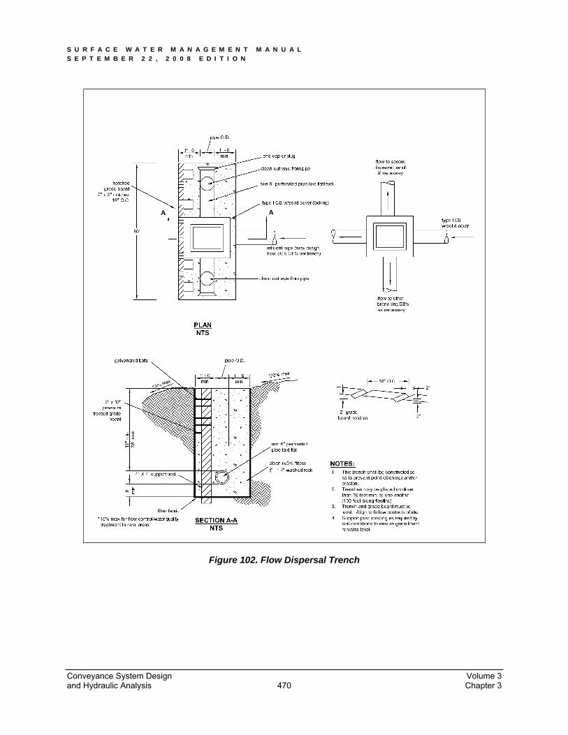
S U R F A C E W A T E R M A N A G E M E N T M A N U A L S E P T E M B E R 2 2 , 2 0 0 8 E D I T I O N
Figure 102. Flow Dispersal Trench
Conveyance System Design Volume 3 and Hydraulic Analysis Chapter 3 470
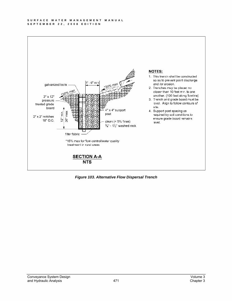
S U R F A C E W A T E R M A N A G E M E N T M A N U A L S E P T E M B E R 2 2 , 2 0 0 8 E D I T I O N
Figure 103. Alternative Flow Dispersal Trench
Conveyance System Design Volume 3 and Hydraulic Analysis Chapter 3 471
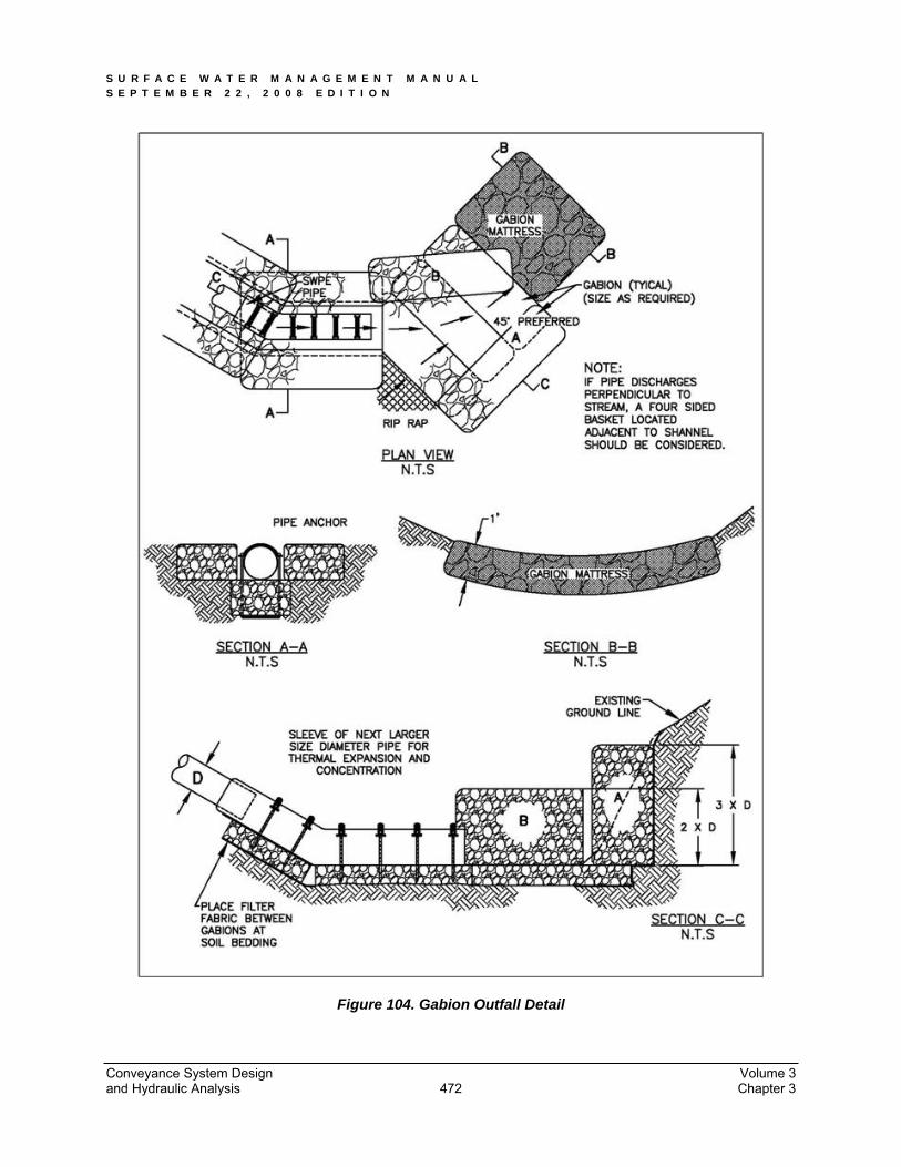
S U R F A C E W A T E R M A N A G E M E N T M A N U A L S E P T E M B E R 2 2 , 2 0 0 8 E D I T I O N
Figure 104. Gabion Outfall Detail
Conveyance System Design Volume 3 and Hydraulic Analysis Chapter 3 472
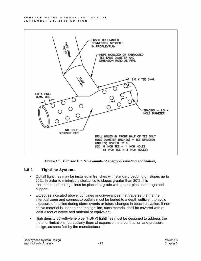
S U R F A C E W A T E R M A N A G E M E N T M A N U A L S E P T E M B E R 2 2 , 2 0 0 8 E D I T I O N
Figure 105. Diffuser TEE (an example of energy dissipating end feature)
3.5.2 Tightline Systems
Outfall tightlines may be installed in trenches with standard bedding on slopes up to 20%. In order to minimize disturbance to slopes greater than 20%, it is recommended that tightlines be placed at grade with proper pipe anchorage and support.
Except as indicated above, tightlines or conveyances that traverse the marine intertidal zone and connect to outfalls must be buried to a depth sufficient to avoid exposure of the line during storm events or future changes in beach elevation. If non-native material is used to bed the tightline, such material shall be covered with at least 3 feet of native bed material or equivalent.
High density polyethylene pipe (HDPP) tightlines must be designed to address the material limitations, particularly thermal expansion and contraction and pressure design, as specified by the manufacturer.
Conveyance System Design Volume 3 and Hydraulic Analysis Chapter 3 473

S U R F A C E W A T E R M A N A G E M E N T M A N U A L S E P T E M B E R 2 2 , 2 0 0 8 E D I T I O N
Due to the ability of HDPP tightlines to transmit flows of very high energy, special consideration for energy dissipation must be made. Details of a sample gabion mattress energy dissipater have been provided as Figure 104. Flows of very high energy will require a specifically engineered energy dissipater structure.
Tightline systems may be needed to prevent aggravation or creation of a downstream erosion problem.
Tightline systems shall have appropriate anchoring designed, both along the slope and to provide anchoring for the entire system.
3.5.3 Habitat Considerations
New pipe outfalls can provide an opportunity for low-cost fish habitat improvements. For example, an alcove of low-velocity water can be created by constructing the pipe outfall and associated energy dissipater back from the stream edge and digging a channel, over widened to the upstream side, from the outfall to the stream. Overwintering juvenile and migrating adult salmonids may use the alcove as shelter during high flows. Potential habitat improvements should be discussed with the Washington Department of Fish and Wildlife biologist prior to inclusion in design.
Bank stabilization, bioengineering and habitat features may be required for disturbed areas.
Outfall structures should be located where they minimize impacts to fish, shellfish, and their habitats.
The City’s Critical Area Preservation Ordinance may regulate activities in these areas.
3.6 Pump Systems Pump systems are only allowed if applied for through the City’s Exceptions process. Feasibility of all other methods of gravity conveyance, infiltration and dispersion shall first be investigated and demonstrated to be infeasible in the following order of preference:
1. Infiltration of surface water on-site.
2. Dispersion of surface water on site.
3. Gravity connection to the City storm drainage system.
4. Pumping to a gravity system.
3.6.1 Design Criteria
If approved by the City Exceptions process (see Volume 1, Section 3.5), the pump system must convey, at a minimum, the peak design flow for the 25-year 24-hour rainfall event. Pump capacity plus system storage or overflow, must convey or store the 100-year, 24-hour storm event.
3.6.2 Pump Requirements
If approved by the City Exemptions/Variance process, proposed pump systems must meet the following minimum requirements:
Conveyance System Design Volume 3 and Hydraulic Analysis Chapter 3 474
S U R F A C E W A T E R M A N A G E M E N T M A N U A L S E P T E M B E R 2 2 , 2 0 0 8 E D I T I O N
The pump system shall be used to convey water from one location or elevation to another within the project site.
The gravity-flow components of the drainage system to and from the pump system must be designed so that pump failure does not result in flooding of a building or emergency access or overflow to a location other than the natural discharge point for the project site.
The pump system must have a dual pump (alternating) equipped with emergency back-up power OR a single pump may be provided without back-up power if the design provides the 100-year 24-hour storage volume.
Pumps, wiring, and control systems shall be intrinsically safe per IBC requirements.
All pump systems must be equipped with an external pump failure and high water alarm system.
The pump system will serve only one lot or business owner.
The pump system must be privately owned and maintained.
The pump system shall not be used to circumvent any other City of Tacoma drainage requirements. Construction and operation of the pump system shall not violate any City of Tacoma requirements.
3.6.3 Additional Requirements
Private pumped stormwater systems will require the following additional items:
Operations and Maintenance Manual describing the system itself and all required maintenance and operating instructions, including procedures to follow in the event of a power outage. All the requirements of Volume 1 Section 4.1 shall be included in the Operations and Maintenance manual.
Notice to Title on the property outlining that a private stormwater system is constructed on the site and that the maintenance of that system is the responsibility of the property owner. Wording of the Notice to Title shall be approved by Environmental Services prior to placing the Notice.
Operations and Maintenance Agreement signed by the property owner and the City. After signature by the city, the agreement shall be recorded with Peirce County and listed in the Notice of Title with the recording number.
All fees associated with preparing and recording documents and placing the Notice to Title shall be the responsibility of the applicant.
Conveyance System Design Volume 3 and Hydraulic Analysis Chapter 3 475
S U R F A C E W A T E R M A N A G E M E N T M A N U A L S E P T E M B E R 2 2 , 2 0 0 8 E D I T I O N
3.6.4 Sump Pumps
The above pump requirements do not apply to internal sump pumps. However, internal sump pumps do require a permit prior to connection to the City storm drainage system.
Sump pumps shall be sized to properly remove water from basements and crawl spaces.
Sump pumps shall NOT be connected to the sanitary sewer system.
Consult the pump manufacturer or an engineer for appropriate sizing of a sump pump.
3.7 Easements, Access, and Dedicated Tracts All publicly owned, manmade drainage facilities and conveyances and all natural channels on the project site used for conveyance of altered flows due to development (including swales, ditches, stream channels, lake shores, wetlands, potholes, estuaries, gullies, ravines, etc.) shall be located within easements or dedicated tracts as required by the City.
Easements shall contain the natural features and facilities and shall allow City access for purposes of inspection, maintenance, repair or replacement, flood control, water quality monitoring, and other activities permitted by law.
For easements dedicated to the City for the purpose of storm drainage, it will not be allowable to place, plant or construct any permanent structures in, upon or under the easement area unless specifically approved in writing by the City of Tacoma’s Director of Public Works, or designee. Such approval shall be drafted as an Addendum to the easement and recorded with the Pierce County Auditor’s Office. Permanent structure shall mean any concrete foundation, concrete slab, wall, rockery, building, deck, overhanging structure, fill material, tree, recreational sport court, carport, portable or non-portable shed, private utilities, fence, or any other improvement that restricts or unreasonably interferes with the City’s access to install, construct, operate, inspect, maintain, remove, repair, and replace the public utilities within the easement area. Permanent structures shall not mean flowers, ground cover and shrubs, (provided they are less than 3 feet in height), lawn, grass, asphalt paving, or gravel.
Preliminary project planning should account for the potential loss of buildable area or the need to purchase more property as a result of drainage facilities and their required easements/tracts.
3.7.1 Stormwater Facilities
3.7.1.1 Public
All drainage facilities such as detention ponds, infiltration systems, and water quality treatment vaults to be maintained by the City shall be located in separate tracts dedicated to the City. Stormwater facility tracts and easements shall include the setbacks required by Chapter 2 of this volume and as indicated in Volume 5.
Conveyance System Design Volume 3 and Hydraulic Analysis Chapter 3 476

S U R F A C E W A T E R M A N A G E M E N T M A N U A L S E P T E M B E R 2 2 , 2 0 0 8 E D I T I O N
3.7.1.2 Private
Privately owned facilities shall be located in separate tracts outside of dedicated public road right-of-way areas. Private systems serving multiple lots require prior City approval. For private systems serving multiple lots within residential developments or other developments, a separate covenant or other guarantee of proper maintenance and access shall be recorded on title and provided to the City.
3.7.2 Conveyance Systems
3.7.2.1 Public
All publicly and privately maintained conveyance systems shall be located in dedicated tracts, drainage easements, or public rights-of-way. Public storm drainage easements shall be a minimum of 20 feet in width. Consult Section 3.4.1.8 of this volume and the Public Works Design Manual for pipe alignment requirements.
All pipes and channels must be located within the easement so that each pipe face or top edge of channel is no closer than 5 feet from its adjacent easement boundary. Pipes greater than 5 feet in diameter and channels with top widths greater than 5 feet shall be placed in easements adjusted accordingly, so as to meet the required dimensions from the easement boundaries.
The depth or proximity of steep slopes to the public system may necessitate a larger easement requirement for future excavation and maintenance purposes. Consult with Table 44 for appropriate widths based on depth of pipe.
Table 44. Additional Storm Drain Easement Widths
INVERT DEPTH WIDTH
10’ 20’10’ - 15’ 25’15’ - 20’ 30’
20’ 40’Greater width may be required for large diameter pipe or unfavorable site conditions.
Pipe shall be installed in center of easement.
If two pipes are to be installed in an easement, add 10 feet to the easement widths listed above. Use the deeper of the two pipes in selecting the easement width from this table. Install pipes with 10 feet of horizontal clearance between them.
3.7.2.2 Private
All privately maintained conveyance systems serving multiple lots/owners shall be located in dedicated tracts, drainage easements, or private roadways. Any new conveyance system located on private property designed to convey drainage from other private properties must be located in a private drainage easement granted to the contributors of stormwater to said systems. The easement shall permit access for maintenance or replacement in the case of failure.
Conveyance System Design Volume 3 and Hydraulic Analysis Chapter 3 477
S U R F A C E W A T E R M A N A G E M E N T M A N U A L S E P T E M B E R 2 2 , 2 0 0 8 E D I T I O N
Unless prohibited by topography or existing site conditions, new conveyance system alignments, on private property, must be located in drainage easements that are adjacent and parallel to property lines.
The depth or proximity of a private system to slopes 20% or greater may necessitate a larger easement for future excavation and maintenance purposes. Typically this requires a 1:1 slope from the bottom of the trench.
Consult with Table 44 for appropriate widths based on depth of pipe.
3.7.2.3 Maintenance Access
A minimum 15-foot wide access easement shall be provided to drainage facilities from a public street or right-of-way. Access easements shall be surfaced with a minimum 12-foot width of crushed rock, or other approved surface to allow year-round equipment access to the facility.
Maintenance access must be provided for all manholes, catch basins, vaults, or other underground drainage facilities operated by the City. Maintenance shall be through an access easement or dedicated tract. These must include a constructed access road per the requirements of Section 2.3.1of this volume.
Maintenance access to privately maintained facilities may also be required.
Conveyance System Design Volume 3 and Hydraulic Analysis Chapter 3 478