Embed Size (px)
Citation preview
127
Unit Page
1
2
3
4
5
6
7
CHAPTER 3WATERCOOLED & CONDENSERLESS LIQUID CHILLERS
AND HEAT PUMPS FOR COMMERCIAL & INDUSTRIAL
APPLICATION. REMOTE CONDENSERS
3
CWW/K 15÷151 128 - 129
CWW/K 182-P÷604-P 130 - 131
CWW/K 182÷604 132 - 133
MEA/K 15÷151 134 - 135
MEA/K 182-P÷604-P 136 - 137
RCA/K 4111÷8222 138 - 139
RCA/K/SL 4111÷8222 140 - 141
RCA/K/SSL 5111÷8222 142 - 143
CWW/K 726-P÷36012-P 144 - 145
CWW/K 726÷36012 146 - 147
CWW/K/A 901÷6202 148 - 149
CWW/IY/WP 1352÷4402 150 - 151
CWW/Y/A 1302÷4802 152 - 153
CWW/K 901÷5802 154 - 155
CWW/Y 1302-B÷9003-B 156 - 157
MEA/Y 1302-B÷9003-B 158 - 159
RCA/Y 8141÷9282 160 - 161
RCA/Y/SL 8231÷9282 162 - 163
RCA/Y/SSL 8151÷9281 164 - 165
CWW/TTH 1701-1÷6606-1 166 - 167
CWW/TTH/DR 1701-1÷6606-1 168 - 169
CWW/TTY 1601-1÷14406-1 170 - 171
CWW/TTY/DR 1601-1÷6204-1 172 - 173
CWW/CCY 4031÷11682 174 - 175
128
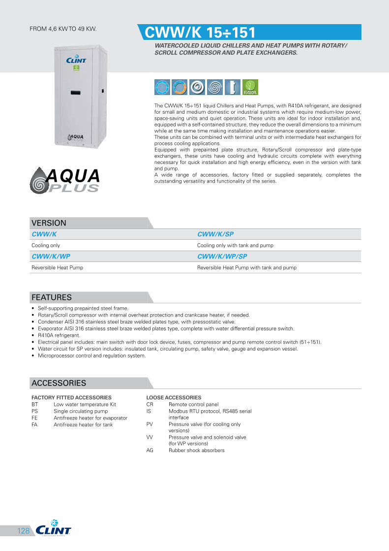
FROM 4,6 KW TO 49 KW.CWW/K 15÷151
WATERCOOLED LIQUID CHILLERS AND HEAT PUMPS WITH ROTARY/
SCROLL COMPRESSOR AND PLATE EXCHANGERS.
The CWW/K 15÷151 liquid Chillers and Heat Pumps, with R410A refrigerant, are designed
for small and medium domestic or industrial systems which require medium-low power,
space-saving units and quiet operation. These units are ideal for indoor installation and,
equipped with a self-contained structure, they reduce the overall dimensions to a minimum
while at the same time making installation and maintenance operations easier.
These units can be combined with terminal units or with intermediate heat exchangers for
process cooling applications.
Equipped with prepainted plate structure, Rotary/Scroll compressor and plate-type
exchangers, these units have cooling and hydraulic circuits complete with everything
necessary for quick installation and high energy efficiency, even in the version with tank
and pump.
A wide range of accessories, factory fitted or supplied separately, completes the
outstanding versatility and functionality of the series.
VERSION
CWW/K CWW/K/SP
Cooling only Cooling only with tank and pump
CWW/K/WP CWW/K/WP/SP
Reversible Heat Pump Reversible Heat Pump with tank and pump
FEATURES
• Self-supporting prepainted steel frame.
• Rotary/Scroll compressor with internal overheat protection and crankcase heater, if needed.
• Condenser AISI 316 stainless steel braze welded plates type, with pressostatic valve.
• Evaporator AISI 316 stainless steel braze welded plates type, complete with water differential pressure switch.
• R410A refrigerant.
• Electrical panel includes: main switch with door lock device, fuses, compressor and pump remote control switch (51÷151).
• Water circuit for SP version includes: insulated tank, circulating pump, safety valve, gauge and expansion vessel.
• Microprocessor control and regulation system.
ACCESSORIES
FACTORY FITTED ACCESSORIES
BT Low water temperature Kit
PS Single circulating pump
FE Antifreeze heater for evaporator
FA Antifreeze heater for tank
LOOSE ACCESSORIES
CR Remote control panel
IS Modbus RTU protocol, RS485 serial
interface
PV Pressure valve (for cooling only
versions)
VV Pressure valve and solenoid valve
(for WP versions)
AG Rubber shock absorbers
CWW/K/SP 91÷151
500 800 800 800
129
CLEARANCE AREA
Electrical board side
1
2
3
4
5
6
7
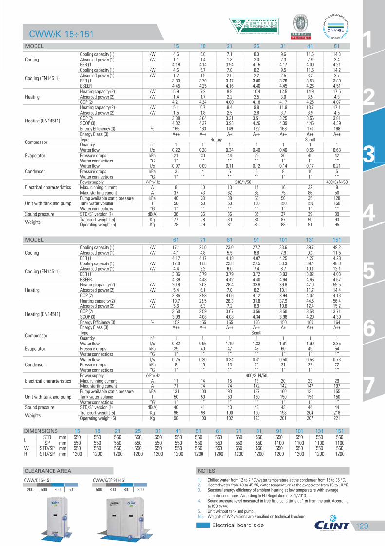
CWW/K 15÷151
MODEL 15 18 21 25 31 41 51
CoolingCooling capacity (1) kW 4.6 5.8 7.1 8.3 9.6 11.6 14.3Absorbed power (1) kW 1.1 1.4 1.8 2.0 2.3 2.9 3.4EER (1) 4.18 4.14 3.94 4.15 4.17 4.00 4.21
Cooling (EN14511)
Cooling capacity (1) kW 4.6 5.7 7.0 8.2 9.5 11.5 14.2Absorbed power (1) kW 1.2 1.5 2.0 2.2 2.5 3.2 3.7EER (1) 3.83 3.70 3.47 3.80 3.78 3.58 3.80ESEER 4.45 4.25 4.16 4.40 4.45 4.26 4.51
HeatingHeating capacity (2) kW 5.9 7.2 8.8 10.4 12.5 14.9 17.5Absorbed power (2) kW 1.4 1.7 2.2 2.5 3.0 3.5 4.3COP (2) 4.21 4.24 4.00 4.16 4.17 4.26 4.07
Heating (EN14511)
Heating capacity (2) kW 5.1 6.7 8.4 9.8 11.9 13.7 17.1Absorbed power (2) kW 1.5 1.8 2.5 2.8 3.7 3.9 4.5COP (2) 3.38 3.64 3.31 3.51 3.25 3.56 3.81SCOP (3) 4.32 4.27 3.93 4.26 4.39 4.45 4.39Energy Efficiency (3) % 165 163 149 162 168 170 168Energy Class (3) A++ A++ A+ A++ A++ A++ A++
CompressorType Rotary ScrollQuantity n° 1 1 1 1 1 1 1
EvaporatorWater flow l/s 0.22 0.28 0.34 0.40 0.46 0.55 0.68Pressure drops kPa 21 30 44 26 30 45 42Water connections ”G 1” 1” 1” 1” 1” 1” 1”
CondenserWater flow l/s 0.07 0.09 0.11 0.12 0.14 0.17 0.21Pressure drops kPa 3 4 5 6 8 10 5Water connections ”G 1” 1” 1” 1” 1” 1” 1”
Electrical characteristicsPower supply V/Ph/Hz 230/1/50 400/3+N/50Max. running current A 8 10 13 14 16 22 9Max. starting current A 37 43 62 62 75 86 50
Unit with tank and pumpPump available static pressure kPa 40 33 38 55 50 35 128Tank water volume l 50 50 50 150 150 150 150Water connections ”G 1” 1” 1” 1” 1” 1” 1”
Sound pressure STD/SP version (4) dB(A) 36 36 36 36 37 39 39
WeightsTransport weight (5) Kg 77 78 80 84 87 90 93Operating weight (5) Kg 78 79 81 85 88 91 95
MODEL 61 71 81 91 101 131 151
CoolingCooling capacity (1) kW 17.1 20.0 23.0 27.7 33.6 39.7 49.2Absorbed power (1) kW 4.1 4.8 5.5 6.8 7.9 9.3 11.5EER (1) 4.17 4.17 4.18 4.07 4.25 4.27 4.28
Cooling (EN14511)
Cooling capacity (1) kW 17.0 19.8 22.8 27.5 33.3 39.4 48.8Absorbed power (1) kW 4.4 5.2 6.0 7.4 8.7 10.1 12.1EER (1) 3.86 3.79 3.79 3.72 3.83 3.92 4.03ESEER 4.39 4.48 4.42 4.40 4.64 4.65 4.67
HeatingHeating capacity (2) kW 20.8 24.3 28.4 33.8 39.8 47.0 59.5Absorbed power (2) kW 5.4 6.1 7.0 8.2 10.1 11.7 14.4COP (2) 3.85 3.98 4.06 4.12 3.94 4.02 4.13
Heating (EN14511)
Heating capacity (2) kW 19.7 22.5 26.3 31.8 37.9 44.5 56.4Absorbed power (2) kW 5.6 6.3 7.2 8.9 10.8 12.4 15.2COP (2) 3.50 3.59 3.67 3.56 3.50 3.58 3.71SCOP (3) 3.99 4.08 4.08 4.34 3.96 4.20 4.30Energy Efficiency (3) % 152 155 155 166 150 160 164Energy Class (3) A++ A++ A++ A++ A+ A++ A++
CompressorType ScrollQuantity n° 1 1 1 1 1 1 1
EvaporatorWater flow l/s 0.82 0.96 1.10 1.32 1.61 1.90 2.35Pressure drops kPa 29 40 47 48 60 49 54Water connections ”G 1” 1” 1” 1” 1” 1” 1”
CondenserWater flow l/s 0.25 0.30 0.34 0.41 0.50 0.58 0.73Pressure drops kPa 8 10 13 20 21 22 22Water connections ”G 1” 1” 1” 1” 1” 1” 1”
Electrical characteristicsPower supply V/Ph/Hz 400/3+N/50Max. running current A 11 14 15 18 20 23 29Max. starting current A 71 74 74 142 142 147 197
Unit with tank and pumpPump available static pressure kPa 131 100 93 187 160 131 155Tank water volume l 50 50 50 150 150 150 150Water connections ”G 1” 1” 1” 1” 1” 1” 1”
Sound pressure STD/SP version (4) dB(A) 40 41 43 43 43 44 44
WeightsTransport weight (5) Kg 96 98 100 190 198 204 218Operating weight (5) Kg 98 100 102 193 201 207 221
DIMENSIONS 15 18 21 25 31 41 51 61 71 81 91 101 131 151
LSTD mm 550 550 550 550 550 550 550 550 550 550 550 550 550 550SP mm 550 550 550 550 550 550 550 550 550 550 1100 1100 1100 1100
W STD/SP mm 550 550 550 550 550 550 550 550 550 550 550 550 550 550H STD/SP mm 1200 1200 1200 1200 1200 1200 1200 1200 1200 1200 1200 1200 1200 1200
3
CWW/K 15÷151
200 500 800 500
NOTES
1. Chilled water from 12 to 7 °C, water temperature at the condenser from 15 to 35 °C.2. Heated water from 40 to 45 °C, water temperature at the evaporator from 15 to 10 °C.3. Seasonal energy efficiency of ambient heating at low temperature with average
climatic conditions. According to EU Regulation n. 811/2013.4. Sound pressure level measured in free field conditions at 1 m from the unit. According
to ISO 3744.5. Unit without tank and pump.N.B. Weights of WP versions are specified on technical brochure.
130
FROM 55 KW TO 195 KW.CWW/K 182-P÷604-P
WATERCOOLED LIQUID CHILLERS AND HEAT PUMPS WITH SCROLL
COMPRESSORS AND PLATE EXCHANGERS.
The CWW/K 182-P÷604-P liquid Chillers and Heat Pumps, with R410A refrigerant, are
designed for medium-sized domestic or industrial systems which require medium power,
space-saving units and quiet operation. This range is ideal for indoor installation and,
equipped with a self-contained structure, it reduces the overall dimensions to a minimum
while at the same time making installation and maintenance operations easier. These units
are used to remove the heat developed during industrial processes or, combined with
terminal units, for the air conditioning of the rooms. They can be supplied with Modbus
RTU protocol through RS485 serial interface. Equipped with polyester powder plate
painting structure, Scroll compressors and plate-type exchangers, these units have cooling
and hydraulic circuits complete with everything necessary for quick installation and high
energy efficiency, even in the version with tank and pump; a series of accessories factory
fitted or supplied separately, like desuperheater and total heat recovery, rounds off the
variety of equipment in this product range.
VERSION
CWW/K CWW/K/WP
Cooling only Reversible Heat Pump
FEATURES
• Self-supporting galvanized steel frame protected with polyester powder painting.
• Scroll compressors with oil sight glass, internal overheat protection and crankcase heater.
• Condenser AISI 316 stainless steel braze welded plate type with one circuit on the refrigerant side and one on the water side in 182-P ÷ 453-P
models; with two independent circuits on the refrigerant side and one on the water side in 524-P÷604-P models.
• Evaporator AISI 316 stainless steel braze welded plate type with one circuit on the refrigerant side and one on the water side in 182-P ÷
453-P models; with two independent circuits on the refrigerant side and one on the water side in 524-P÷604-P models, complete with water
differential pressure switch.
• R410A refrigerant.
• Electrical board includes: main switch with door safety interlock, fuses, overload protection for compressors.
• Microprocessor control and regulation system.
ACCESSORIES
FACTORY FITTED ACCESSORIES
IM Automatic circuit breakers
SL Unit silencement
RFM Cooling circuit shut-off valve on
discharge line
RFL Cooling circuit shut-off valve on
liquid line
BT Low water temperature Kit
DS Desuperheater
RT Total heat recovery
FE Antifreeze heater for evaporator
FA Antifreeze heater for tank
SS Soft start
IS Modbus RTU protocol, RS485 serial
interface
LOOSE ACCESSORIES
MN High and low pressure gauges
CR Remote control panel
SPU Inertial tank and single circulating
pump
SPD Inertial tank and double circulating
pump
PV2 2-Way electronic pressostatic valve
PV3 3-Way electronic pressostatic valve
AG Rubber shock absorbers
AM Spring shock absorbers
131
CLEARANCE AREA
Electrical board side
1
2
3
4
5
6
7
CWW/K 182-P÷604-P
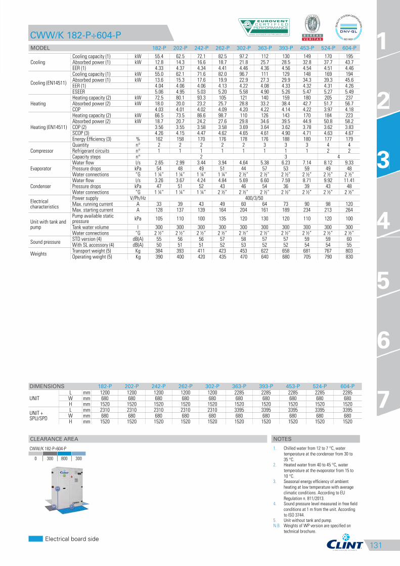
MODEL 182-P 202-P 242-P 262-P 302-P 363-P 393-P 453-P 524-P 604-P
CoolingCooling capacity (1) kW 55.4 62.5 72.1 82.5 97.2 112 130 149 170 195Absorbed power (1) kW 12.8 14.3 16.6 18.7 21.8 25.7 28.5 32.8 37.7 43.7EER (1) 4.33 4.37 4.34 4.41 4.46 4.36 4.56 4.54 4.51 4.46
Cooling (EN14511)
Cooling capacity (1) kW 55.0 62.1 71.6 82.0 96.7 111 129 148 169 194Absorbed power (1) kW 13.6 15.3 17.6 19.9 22.9 27.3 29.9 34.3 39.3 45.6EER (1) 4.04 4.06 4.06 4.13 4.22 4.08 4.33 4.32 4.31 4.26ESEER 5.06 4.95 5.03 5.20 5.58 4.90 5.26 5.47 5.27 5.49
HeatingHeating capacity (2) kW 72.5 80.1 93.3 105 121 140 159 180 205 237Absorbed power (2) kW 18.0 20.0 23.2 25.7 28.8 33.2 38.4 42.7 51.7 56.7COP 4.03 4.01 4.02 4.09 4.20 4.22 4.14 4.22 3.97 4.18
Heating (EN14511)
Heating capacity (2) kW 66.5 73.5 86.6 98.7 110 126 143 170 184 223Absorbed power (2) kW 18.7 20.7 24.2 27.6 29.8 34.6 39.5 44.9 50.8 58.2COP (2) 3.56 3.55 3.58 3.58 3.69 3.64 3.62 3.78 3.62 3.83SCOP (3) 4.26 4.15 4.47 4.62 4.65 4.61 4.90 4.71 4.63 4.67Energy Efficiency (3) % 162 158 170 176 178 176 188 180 177 179
CompressorQuantity n° 2 2 2 2 2 3 3 3 4 4Refrigerant circuits n° 1 1 1 1 1 1 1 1 2 2Capacity steps n° 2 3 4
EvaporatorWater flow l/s 2.65 2.99 3.44 3.94 4.64 5.38 6.23 7.14 8.12 9.33Pressure drops kPa 54 48 49 51 44 57 53 59 49 48Water connections ”G 1 ¼” 1 ¼” 1 ¼” 1 ¼” 2 ½” 2 ½” 2 ½” 2 ½” 2 ½” 2 ½”
CondenserWater flow l/s 3.26 3.67 4.24 4.84 5.69 6.60 7.59 8.71 9.92 11.41Pressure drops kPa 47 51 52 43 46 54 36 39 43 48Water connections ”G 1 ¼” 1 ¼” 1 ¼” 2 ½” 2 ½” 2 ½” 2 ½” 2 ½” 2 ½” 2 ½”
Electrical characteristics
Power supply V/Ph/Hz 400/3/50Max. running current A 33 39 43 49 60 64 73 90 98 120Max. starting current A 128 137 139 164 204 161 189 234 213 264
Unit with tank and pump
Pump available static pressure
kPa 105 110 100 135 120 130 120 110 120 100
Tank water volume l 300 300 300 300 300 300 300 300 300 300Water connections ”G 2 ½” 2 ½” 2 ½” 2 ½” 2 ½” 2 ½” 2 ½” 2 ½” 2 ½” 2 ½”
Sound pressureSTD version (4) dB(A) 55 56 56 57 58 57 57 59 59 60With SL accessory (4) dB(A) 50 51 51 52 53 52 52 54 54 55
WeightsTransport weight (5) Kg 384 393 411 423 453 622 658 681 767 803Operating weight (5) Kg 390 400 420 435 470 640 680 705 790 830
DIMENSIONS 182-P 202-P 242-P 262-P 302-P 363-P 393-P 453-P 524-P 604-P
UNITL mm 1200 1200 1200 1200 1200 2285 2285 2285 2285 2285
W mm 680 680 680 680 680 680 680 680 680 680H mm 1520 1520 1520 1520 1520 1520 1520 1520 1520 1520
UNIT +SPU/SPD
L mm 2310 2310 2310 2310 2310 3395 3395 3395 3395 3395W mm 680 680 680 680 680 680 680 680 680 680H mm 1520 1520 1520 1520 1520 1520 1520 1520 1520 1520
3
CWW/K 182-P÷604-P
0 300 800 300
NOTES
1. Chilled water from 12 to 7 °C, water
temperature at the condenser from 30 to
35 °C.2. Heated water from 40 to 45 °C, water
temperature at the evaporator from 15 to
10 °C.3. Seasonal energy efficiency of ambient
heating at low temperature with average
climatic conditions. According to EU
Regulation n. 811/2013.4. Sound pressure level measured in free field
conditions at 1 m from the unit. According
to ISO 3744.5. Unit without tank and pump.N.B. Weights of WP version are specified on
technical brochure.
132
FROM 57 KW TO 196 KW.CWW/K 182÷604
WATERCOOLED LIQUID CHILLERS AND HEAT PUMPS WITH SCROLL
COMPRESSORS AND SHELL AND TUBE EXCHANGERS.
The CWW/K 182÷604 liquid Chillers and Heat Pumps, with R410A refrigerant, are designed
for medium-sized domestic or industrial systems which require medium power, space-
saving units and quiet operation. This range is ideal for indoor installation and, equipped
with a self-contained structure, it reduces the overall dimensions to a minimum while at
the same time making installation and maintenance operations easier. These units are
used to remove the heat developed during industrial processes or, combined with terminal
units, for the air conditioning of the rooms. They can be supplied with Modbus RTU
protocol through RS485 serial interface. Equipped with Scroll compressors and shell and
tube exchangers, these units have cooling and hydraulic circuits complete with everything
necessary for quick installation and high energy efficiency, even in the version with tank
and pump; a series of accessories, factory fitted or supplied separately, like desuperheater
and total heat recovery, rounds off the variety of equipment in this product range.
VERSION
CWW/K CWW/K/WP
Cooling only Reversible Heat Pump
CWW/K/SSL CWW/K/WP/SSL
Super silenced cooling only Super silenced reversible Heat Pump
FEATURES
• Self-supporting galvanized steel frame protected with polyester powder painting.
• Scroll compressors with oil sight glass, internal overheat protection and crankcase heater.
• Shell and tube type condenser with one circuit on the refrigerant side and one on the water side in 182 ÷ 453 models; with two independent
circuits on the refrigerant side and one on the water side in 524÷604 models.
• Shell and tube type evaporator with one circuit on the refrigerant side and one on the water side in 182 ÷ 453 models; with two independent
circuits on the refrigerant side and one on the water side in 524÷604 models, complete with water differential pressure switch.
• R410A refrigerant.
• Electrical board includes: main switch with door safety interlock, fuses, overload protection for compressors.
• Microprocessor control and regulation system.
ACCESSORIES
FACTORY FITTED ACCESSORIES
IM Automatic circuit breakers
SL Unit silencement
RFM Cooling circuit shut-off valve on
discharge line
RFL Cooling circuit shut-off valve on
liquid line
BT Low water temperature Kit
HR Desuperheater
HRT Total heat recovery
SP Inertial tank
SPU Inertial tank and single circulating
pump
SPD Inertial tank and double circulating
pump
LOOSE ACCESSORIES
MN High and low pressure gauges
CR Remote control panel
PV2 2-Way electronic pressostatic valve
PV3 3-Way electronic pressostatic valve
AG Rubber shock absorbers
AM Spring shock absorbers
FL Flow switch
FE Antifreeze heater for evaporator
FB Antifreeze heater for evaporator
and tank
SS Soft start
IS Modbus RTU protocol, RS485 serial
interface
133
CLEARANCE AREA
Electrical board side
1
2
3
4
5
6
7
CWW/K 182÷604
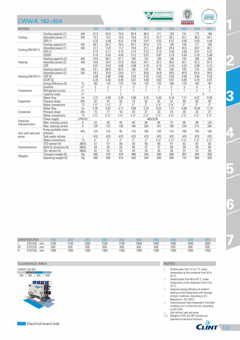
MODEL 182 202 242 262 302 363 393 453 524 604
CoolingCooling capacity (1) kW 57.0 62.6 70.9 82.9 98.3 111 129 151 172 196Absorbed power (1) kW 13.2 14.3 16.4 18.9 22.0 25.7 28.2 33.1 38.2 44.1EER (1) 4.32 4.38 4.32 4.39 4.47 4.32 4.57 4.56 4.50 4.44
Cooling (EN14511)
Cooling capacity (1) kW 56.7 62.2 70.4 82.2 97.6 110 128 150 171 195Absorbed power (1) kW 13.7 14.9 17.2 19.9 23.1 26.9 29.4 34.5 39.7 45.7EER (1) 4.14 4.17 4.10 4.14 4.23 4.10 4.36 4.36 4.31 4.27ESEER 5.19 5.03 4.93 5.12 5.57 4.87 5.19 5.54 5.19 5.48
HeatingHeating capacity (2) kW 74.6 80.3 91.7 106 122 139 158 182 208 238Absorbed power (2) kW 18.6 20.0 22.9 26.0 29.1 33.2 38.0 43.1 52.3 57.3COP 4.01 4.02 4.00 4.08 4.19 4.19 4.16 4.22 3.98 4.15
Heating (EN14511)
Heating capacity (2) kW 75.1 80.9 92.5 106 123 140 159 183 210 239Absorbed power (2) kW 19.3 20.9 24.0 27.1 30.6 34.8 39.6 44.8 54.4 59.4COP (2) 3.89 3.88 3.86 3.92 4.03 4.03 4.02 4.08 3.85 4.03SCOP (3) 4.26 4.46 4.45 4.61 4.68 4.62 4.91 4.69 4.76 4.87Energy Efficiency (3) % 162 170 170 176 179 176 188 179 182 187
CompressorQuantity n° 2 2 2 2 2 3 3 3 4 4Refrigerant circuits n° 1 1 1 1 1 1 1 1 2 2Capacity steps n° 2 3 4
EvaporatorWater flow l/s 2.72 2.99 3.39 3.96 4.70 5.30 6.16 7.21 8.22 9.36Pressure drops kPa 32 42 55 74 62 55 57 49 63 49Water connections ”G 1 ½” 1 ½” 2” 2” 2” 2 ½” 2 ½” 3” 3” 3”
CondenserWater flow l/s 3.35 3.67 4.17 4.86 5.75 6.53 7.51 8.80 10.04 11.47Pressure drops kPa 15 17 18 20 27 33 23 30 20 27Water connections ”G 2 ½” 2 ½” 2 ½” 2 ½” 2 ½” 2 ½” 2 ½” 2 ½” 2 ½” 2 ½”
Electrical characteristics
Power supply V/Ph/Hz 400/3/50Max. running current A 33 39 43 49 60 64 73 90 98 120Max. starting current A 128 137 139 164 204 161 189 234 213 264
Unit with tank and pump
Pump available static pressure
kPa 125 115 95 110 100 130 115 100 105 100
Tank water volume l 470 470 470 470 470 470 470 470 670 670Water connections ”G 2” 2” 2” 2” 2” 2 ½” 2 ½” 2 ½” 2 ½” 2 ½”
Sound pressureSTD version (4) dB(A) 57 57 58 59 60 60 61 62 62 63With SL accessory (4) dB(A) 54 54 55 56 57 57 58 59 59 60SSL version (4) dB(A) 52 52 53 54 55 55 56 57 57 58
WeightsTransport weight (5) Kg 465 470 478 488 504 590 606 657 840 856Operating weight (5) Kg 495 500 510 520 540 630 650 710 900 920
DIMENSIONS 182 202 242 262 302 363 393 453 524 604
L STD/SSL mm 2100 2100 2300 2100 2700 2400 2400 2400 2400 2600W STD/SSL mm 830 830 830 830 830 830 830 830 830 830H STD/SSL mm 1300 1300 1300 1300 1300 1300 1300 1300 1450 1450
3
CWW/K 182÷604
500 500 800 1500
NOTES
1. Chilled water from 12 to 7 °C, water
temperature at the condenser from 30 to
35 °C.2. Heated water from 40 to 45 °C, water
temperature at the evaporator from 15 to
10 °C.3. Seasonal energy efficiency of ambient
heating at low temperature with average
climatic conditions. According to EU
Regulation n. 811/2013.4. Sound pressure level measured in free field
conditions at 1 m from the unit. According
to ISO 3744.5. Unit without tank and pump.N.B. Weights of SSL and WP versions are
specified on technical brochure.
134
FROM 4,0 KW TO 42 KW.MEA/K 15÷151
CONDENSERLESS LIQUID CHILLERS AND HEAT PUMPS WITH ROTARY/
SCROLL COMPRESSOR AND PLATE EXCHANGER.
The liquid Chillers and Heat Pumps for remote condensation of the MEA/K 15÷151, with
R410A refrigerant, series are designed for domestic or service sector systems which
require medium power, space-saving units and quiet operation. Combined with remote
condenser, these units are ideal for indoor installation and, equipped with a self-contained
structure, they reduce the overall dimensions to a minimum while at the same time making
installation and maintenance operations easier.
Equipped with prepainted plate structure, Rotary/Scroll compressor and plate-type
exchanger, these units have cooling and hydraulic circuits designed for quick installation
and high energy efficiency, even in the version with tank and pump.
A wide range of accessories, factory fitted or supplied separately, completes the
outstanding versatility and functionality of the series.
VERSION
MEA/K MEA/K/SP
Cooling only Cooling only with tank and pump
MEA/K/WP MEA/K/WP/SP
Reversible Heat Pump Reversible Heat Pump with tank and pump
FEATURES
• Self-supporting prepainted steel frame.
• Rotary/Scroll compressor with internal overheat protection and crankcase heater, if needed.
• Evaporator AISI 316 stainless steel braze welded plates type, complete with water differential pressure switch.
• R410A refrigerant.
• Electrical panel includes: main switch with door lock device, fuses, compressor and pump remote control switch (51÷151).
• Water circuit for SP version includes: insulated tank, circulator or pump, safety valve, gauge and expansion vessel.
• Microprocessor control and regulation system.
ACCESSORIES
FACTORY FITTED ACCESSORIES
BT Low water temperature Kit
PS Single circulating pump
RL Liquid receiver
FE Antifreeze heater for evaporator
FA Antifreeze heater for tank
LOOSE ACCESSORIES
CR Remote control panel
IS Modbus RTU protocol, RS485 serial
interface
AG Rubber shock absorbers
135
CLEARANCE AREA
Electrical board side
1
2
3
4
5
6
7
MEA/K 15÷151
MODEL 15 18 21 25 31 41 51
CoolingCooling capacity (1) kW 4.0 5.1 6.2 7.3 8.5 10.1 12.1Absorbed power (1) kW 1.4 1.8 2.1 3.0 3.3 3.7 3.3
HeatingHeating capacity (2) kW 5.1 6.4 8.2 9.4 10.7 13.2 15.5Absorbed power (2) kW 1.5 1.9 2.4 2.7 3.0 4.2 4.5
CompressorType Rotary ScrollQuantity n° 1 1 1 1 1 1 1
EvaporatorWater flow l/s 0.19 0.24 0.30 0.35 0.41 0.48 0.58Pressure drops kPa 15 15 20 18 20 25 35Water connections ”G 1” 1” 1” 1” 1” 1” 1”
ConnectionsDelivery line Ø mm 12 12 12 12 12 12 16Liquid line Ø mm 10 10 10 10 10 10 12
Electrical characteristics
Power supply V/Ph/Hz 230/1/50 400/3+N/50Max. running current A 8 10 13 14 16 22 9Max. starting current A 37 43 62 62 75 86 50
Unit with tank and pump
Pump available static pressure
kPa 50 45 75 70 70 60 180
Tank water volume l 50 50 50 50 50 50 50Water connections ”G 1” 1” 1” 1” 1” 1” 1”
Sound pressure STD version (3) dB(A) 36 36 36 36 37 39 39
WeightsTransport weight (4) Kg 74 75 77 81 84 87 86Operating weight (4) Kg 75 76 78 82 85 88 88
MODEL 61 71 81 91 101 131 151
CoolingCooling capacity (1) kW 14.5 17.0 20.0 24.1 28.8 33.9 41.5Absorbed power (1) kW 5.2 6.0 7.1 7.8 9.3 10.9 13.3
HeatingHeating capacity (2) kW 18.5 22.0 25.9 30.4 36.4 43.0 53.2Absorbed power (2) kW 5.5 6.5 7.7 8.3 10.1 11.7 14.2
CompressorType ScrollQuantity n° 1 1 1 1 1 1 1
EvaporatorWater flow l/s 0.69 0.81 0.96 1.15 1.38 1.62 1.98Pressure drops kPa 28 35 39 40 45 40 40Water connections ”G 1” 1” 1” 1” 1” 1” 1”
ConnectionsDelivery line Ø mm 16 16 16 22 22 22 22Liquid line Ø mm 12 12 12 12 12 12 16
Electrical characteristics
Power supply V/Ph/Hz 400/3+N/50Max. running current A 11 14 15 18 20 23 29Max. starting current A 71 74 74 142 142 147 197
Unit with tank and pump
Pump available static pressure
kPa 170 140 110 215 130 155 235
Tank water volume l 50 50 50 150 150 150 150Water connections ”G 1” 1” 1” 1” 1” 1” 1”
Sound pressure STD version (3) dB(A) 40 41 43 43 43 44 44
WeightsTransport weight (4) Kg 89 91 93 183 189 195 206Operating weight (4) Kg 91 93 95 186 192 198 209
DIMENSIONS 15 18 21 25 31 41 51 61 71 81 91 101 131 151
LSTD mm 550 550 550 550 550 550 550 550 550 550 550 550 550 550SP mm 550 550 550 550 550 550 550 550 550 550 1100 1100 1100 1100
W STD/SP mm 550 550 550 550 550 550 550 550 550 550 550 550 550 550H STD/SP mm 1200 1200 1200 1200 1200 1200 1200 1200 1200 1200 1200 1200 1200 1200
3
MEA/K 15÷151
200 500 800 500
MEA/K/SP 15÷151
500 800 800 800
NOTES
1. Chilled water from 12 to 7 °C, condensing
temperature 50 °C.2. Heated water from 40 to 45 °C, evaporating
temperature 0 °C.3. Sound pressure level measured in free field
conditions at 1 m from the unit. According
to ISO 3744.4. Unit without tank and pump.N.B. Weights of WP versions are specified on
technical brochure.
136
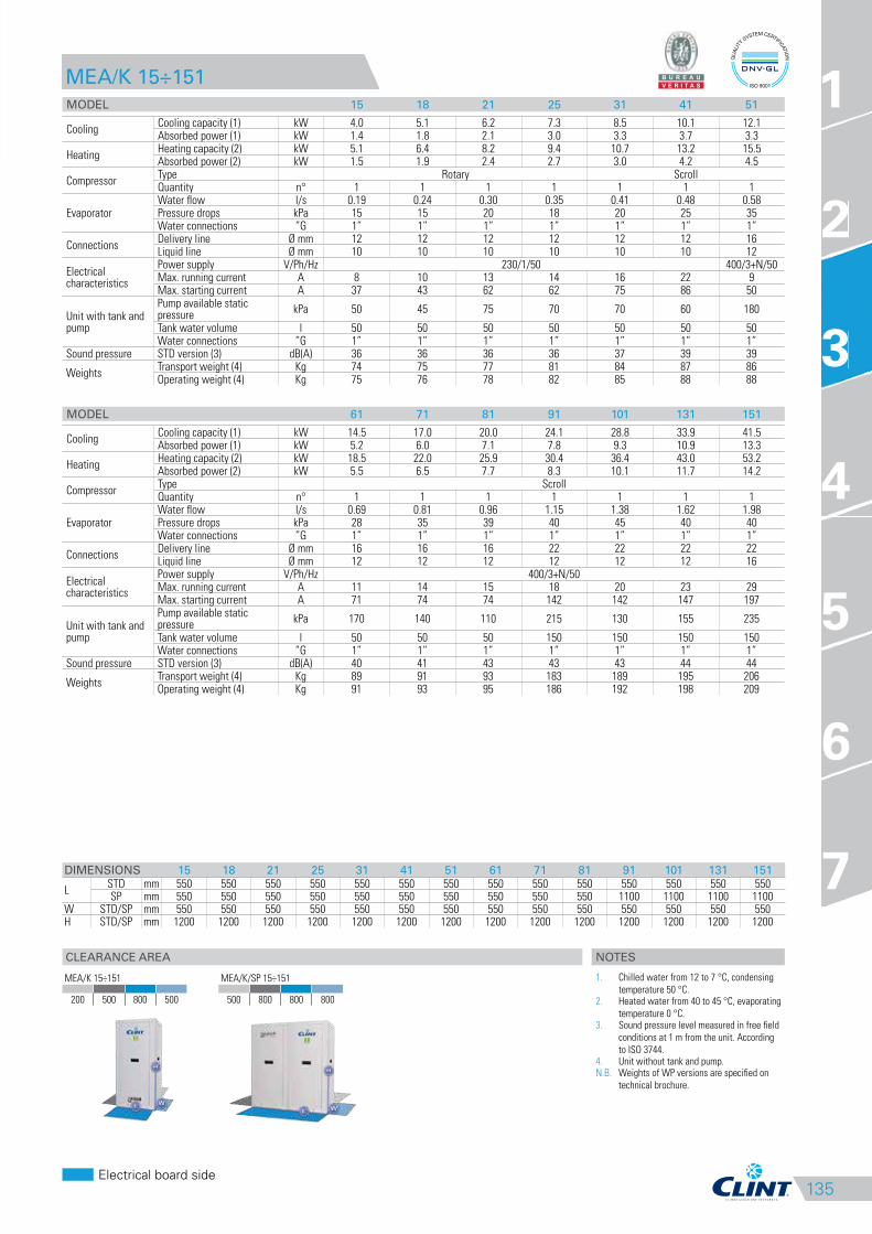
FROM 51 KW TO 176 KW.MEA/K 182-P÷604-P
CONDENSERLESS LIQUID CHILLERS AND HEAT PUMPS WITH SCROLL
COMPRESSORS AND PLATE EXCHANGER.
MEA/K 182-P÷604-P series liquid Chillers and Heat Pumps for remote condensation, with
R410A refrigerant, are designed to meet the needs of residential or industrial-type systems
requiring high power together with space-saving and quiet operation. These units are ideal
for indoor installation and, equipped with a self-contained structure, minimise overall
dimensions while also facilitating installation and maintenance operations. Equipped with
polyester plate powder painting structure, Scroll compressors and plate-type exchanger
they have refrigerant and hydraulic circuits, even in the version with tank, with pump or
tank and pump, complete with everything necessary for quick installation operations and
for high energy efficiencies. A number of accessories, factory fitted or supplied separately,
such as the desuperheater or the total heat recuperator, enhance and complete the
equipment of this range.
VERSION
MEA/K MEA/K/WP
Cooling only Reversible Heat Pump
FEATURES
• Self-supporting galvanized steel frame protected with polyester powder painting.
• Scroll compressors with oil sight glass, internal overheat protection and crankcase heater.
• Evaporator AISI 316 stainless steel braze welded plate type with one circuit on the refrigerant side and one on the water side in 182-P ÷
453-P models; with two independent circuits on the refrigerant side and one on the water side in 524-P÷604-P models, complete with water
differential pressure switch.
• R410A refrigerant.
• Electrical board includes: main switch with door safety interlock, fuses, overload protection for compressors.
• Microprocessor control and regulation system.
ACCESSORIES
FACTORY FITTED ACCESSORIES
IM Automatic circuit breakers
SL Unit silencement
RFM Cooling circuit shut-off valve on
discharge line
RFL Cooling circuit shut-off valve on
liquid line
BT Low water temperature Kit
DS Desuperheater
RT Total heat recovery
FE Antifreeze heater for evaporator
SS Soft start
IS Modbus RTU protocol, RS485 serial
interface
LOOSE ACCESSORIES
MN High and low pressure gauges
CR Remote control panel
SPU Inertial tank and single circulating
pump
SPD Inertial tank and double circulating
pump
AG Rubber shock absorbers
AM Spring shock absorbers

137
CLEARANCE AREA
Electrical board side
1
2
3
4
5
6
7
MEA/K 182-P÷604-P
MODEL 182-P 202-P 242-P 262-P 302-P 363-P 393-P 453-P 524-P 604-P
CoolingCooling capacity (1) kW 50.8 57.1 64.3 73.6 87.1 98.8 114 134 149 176Absorbed power (1) kW 15.4 17.3 19.0 21.6 25.8 29.4 32.9 38.7 43.5 51.5
HeatingHeating capacity (2) kW 59.5 65.8 74.3 84.7 96.5 107 122 148 157 194Absorbed power (2) kW 18.0 20.0 22.3 24.7 27.8 32.8 37.2 41.1 50.8 56.5
CompressorQuantity n° 2 2 2 2 2 3 3 3 4 4Refrigerant circuits n° 1 1 1 1 1 1 1 1 2 2Capacity steps n° 2 3 4
EvaporatorWater flow l/s 2.43 2.73 3.07 3.52 4.16 4.72 5.42 6.41 7.10 8.41Pressure drops kPa 47 42 41 42 40 48 44 51 41 40Water connections ”G 1 ¼” 1 ¼” 1 ¼” 1 ¼” 2 ½” 2 ½” 2 ½” 2 ½” 2 ½” 2 ½”
ConnectionsDelivery line Ø mm 28 28 28 28 28 28 28 28 2 x 28 2 x 28Liquid line Ø mm 22 22 22 22 22 22 22 22 2 x 22 2 x 22
Electrical characteristics
Power supply V/Ph/Hz 400/3/50Max. running current A 33 39 43 49 60 64 73 90 98 120Max. starting current A 128 137 139 164 204 161 189 234 213 264
Version with tank and pump
Pump available static pressure
kPa 105 110 100 135 120 130 120 110 120 100
Tank water volume l 300 300 300 300 300 300 300 300 300 300Water connections ”G 2 ½” 2 ½” 2 ½” 2 ½” 2 ½” 2 ½” 2 ½” 2 ½” 2 ½” 2 ½”
Sound pressureSTD version (3) dB(A) 55 56 56 57 58 57 57 59 59 60With SL accessory (3) dB(A) 50 51 51 52 53 52 52 54 54 55
WeightsTransport weight (4) Kg 347 357 376 386 397 562 581 595 669 708Operating weight (4) Kg 350 360 380 390 405 570 590 605 680 720
3
MEA/K 182-P÷604-P
0 300 800 300
NOTES
1. Chilled water from 12 to 7 °C, condensing
temperature 50 °C.2. Heated water from 40 to 45 °C, evaporating
temperature 0 °C.3. Sound pressure level measured in free field
conditions at 1 m from the unit. According
to ISO 3744.4. Unit without tank and pump.N.B. Weights of WP version are specified on
technical brochure.
DIMENSIONS 182-P 202-P 242-P 262-P 302-P 363-P 393-P 453-P 524-P 604-P
UNITL mm 1200 1200 1200 1200 1200 2285 2285 2285 2285 2285
W mm 680 680 680 680 680 680 680 680 680 680H mm 1520 1520 1520 1520 1520 1520 1520 1520 1520 1520
UNIT +SPU/SPD
L mm 2310 2310 2310 2310 2310 3395 3395 3395 3395 3395W mm 680 680 680 680 680 680 680 680 680 680H mm 1520 1520 1520 1520 1520 1520 1520 1520 1520 1520
138
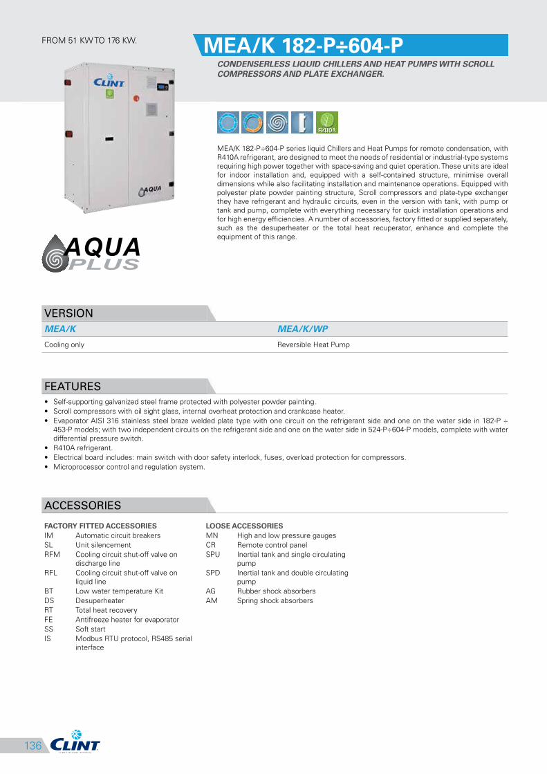
RCA/K 4111÷8222
REMOTE AIRCOOLED CONDENSERS WITH AXIAL FANS.
The Remote aircooled Condensers with axial fans of the RCA/K series are designed to be
combined with evaporating units with R410A refrigerant (MEA/K).
These units, available in three configurations depending on the degree of noiselessness
required: Standard, Silenced (SL) and Super Silenced (SSL), are equipped with latest
generation axial fans, with motor fan shrouds having a large radius of curvature to eliminate
all the air flow turbulence and with larger plenum to uniform the air distribution on the
cooling coil.
The units can be installed with either horizontal or vertical air delivery, as needed.
VERSION
RCA/K
Base unit
FEATURES
• Frame in oven painted with a polyurethane resin and galvanised steel casework.
• The cowlings of the motorfans are made with a wide bending radius to eliminate any turbulence in the airflow.
• Heat exchanger is made with corrugated tubes with a greater heat exchange surface, fins cut with a special louver configuration to give the
best external coefficient of heat exchange.
COMBINATIONS
MEA/K 15 18 21 25 31 41 51 61 71 81
RCA/K 4111 4111 4111 4111 4111 4112 5111 5111 5112 5113
MEA/K 91 101 131 151
RCA/K 6111 6112 6113 5121
MEA/K 182-P 202-P 242-P 262-P 302-P 363-P 393-P 453-P 524-P 604-P
RCA/K 6114 6121 6122 6123 6124 6125 6131 6132 8221 8222
ACCESSORIES
FACTORY FITTED ACCESSORIES
SD Wiring integrated in branch circuit
box
FR Fan speed controller
LOOSE ACCESSORIES
SVV Supports for vertical air flow
versions
139
CLEARANCE AREA
Electrical board side
1
2
3
4
5
6
7
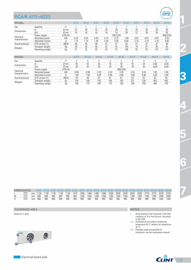
RCA/K 4111÷8222
MODEL 4111 4112 5111 5112 5113 5121 6111 6112 6113 6114
Fan Quantity n° 1 1 1 1 1 1 1 1 1 1
ConnectionsIn Ø mm 22 28 22 28 28 35 28 35 35 35Out Ø mm 18 18 18 18 18 28 22 28 28 28
Electrical characteristics
Power supply V/Ph/Hz 230/1/50 400/3/50Absorbed power kW 0.24 0.24 0.30 0.75 0.75 1.50 0.67 0.67 0.67 3.20Absorbed current A 1.10 1.10 1.30 3.30 3.30 6.60 3.10 3.10 3.10 4.90
Sound pressure STD version (1) dB(A) 46 46 38 47 47 50 47 47 47 58
WeightsTransport weight Kg 30 30 48 52 55 104 79 87 95 95Operating weight Kg 31 32 49 54 57 109 82 92 101 101
MODEL 6121 6122 6123 6124 6125 6131 6132 8221 8222
Fan Quantity n° 2 2 2 2 2 3 3 4 4
ConnectionsIn Ø mm 35 42 35 42 42 42 54 2x35 2x35Out Ø mm 28 35 28 35 35 35 35 2x28 2x28
Electrical characteristics
Power supply V/Ph/Hz 400/3/50Absorbed power kW 0.99 0.99 3.20 3.20 3.20 3.20 3.20 1.85 1.85Absorbed current A 1.60 1.60 4.90 4.90 4.90 4.90 4.90 2.85 2.85
Sound pressure STD version (1) dB(A) 49 49 61 61 61 63 63 52 54
WeightsTransport weight Kg 150 166 150 166 183 221 236 462 462Operating weight Kg 156 175 156 175 195 230 250 480 476
DIMENSIONS 4111 4112 5111 5112 5113 5121 6111 6112 6113 6114 6121 6122 6123 6124 6125 6131 6132 8221 8222
L STD mm 1130 1130 1130 1130 1130 1910 1490 1490 1490 1490 2630 2630 2630 2630 2630 3770 3770 3230 3230W STD mm 900 900 900 900 900 900 1260 1260 1260 1260 1260 1260 1260 1260 1260 1260 1260 2400 2400H STD mm 980 980 980 980 980 990 990 990 990 990 990 990 990 990 990 990 990 1565 1565
3
RCA/K 4111÷8222
NOTES
1. Sound pressure level measured in free field
conditions at 10 m from the unit. According
to ISO 3744.N.B. Combinations are made at condensing
temperature 50 °C, ambient air temperature
35 °C.N.B. Clearance areas are specified on
installation, use and maintenance manual.
140
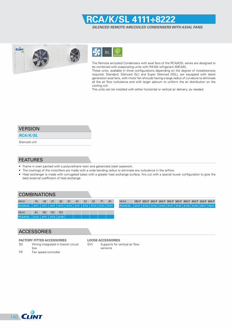
RCA/K/SL 4111÷8222
SILENCED REMOTE AIRCOOLED CONDENSERS WITH AXIAL FANS.
The Remote aircooled Condensers with axial fans of the RCA/K/SL series are designed to
be combined with evaporating units with R410A refrigerant (MEA/K).
These units, available in three configurations depending on the degree of noiselessness
required: Standard, Silenced (SL) and Super Silenced (SSL), are equipped with latest
generation axial fans, with motor fan shrouds having a large radius of curvature to eliminate
all the air flow turbulence and with larger plenum to uniform the air distribution on the
cooling coil.
The units can be installed with either horizontal or vertical air delivery, as needed.
VERSION
RCA/K/SL
Silenced unit
FEATURES
• Frame in oven painted with a polyurethane resin and galvanised steel casework.
• The cowlings of the motorfans are made with a wide bending radius to eliminate any turbulence in the airflow.
• Heat exchanger is made with corrugated tubes with a greater heat exchange surface, fins cut with a special louver configuration to give the
best external coefficient of heat exchange.
COMBINATIONS
MEA/K 15 18 21 25 31 41 51 61 71 81
RCA/K/SL 4111 4111 4111 4112 4113 5111 5112 5113 5121 5121
MEA/K 91 101 131 151
RCA/K/SL 5121 6111 6112 6120
MEA/K 182-P 202-P 242-P 262-P 302-P 363-P 393-P 453-P 524-P 604-P
RCA/K/SL 6121 6122 6123 6124 6131 6132 6133 6134 8221 8222
ACCESSORIES
FACTORY FITTED ACCESSORIES
SD Wiring integrated in branch circuit
box
FR Fan speed controller
LOOSE ACCESSORIES
SVV Supports for vertical air flow
versions
141
CLEARANCE AREA
Electrical board side
1
2
3
4
5
6
7
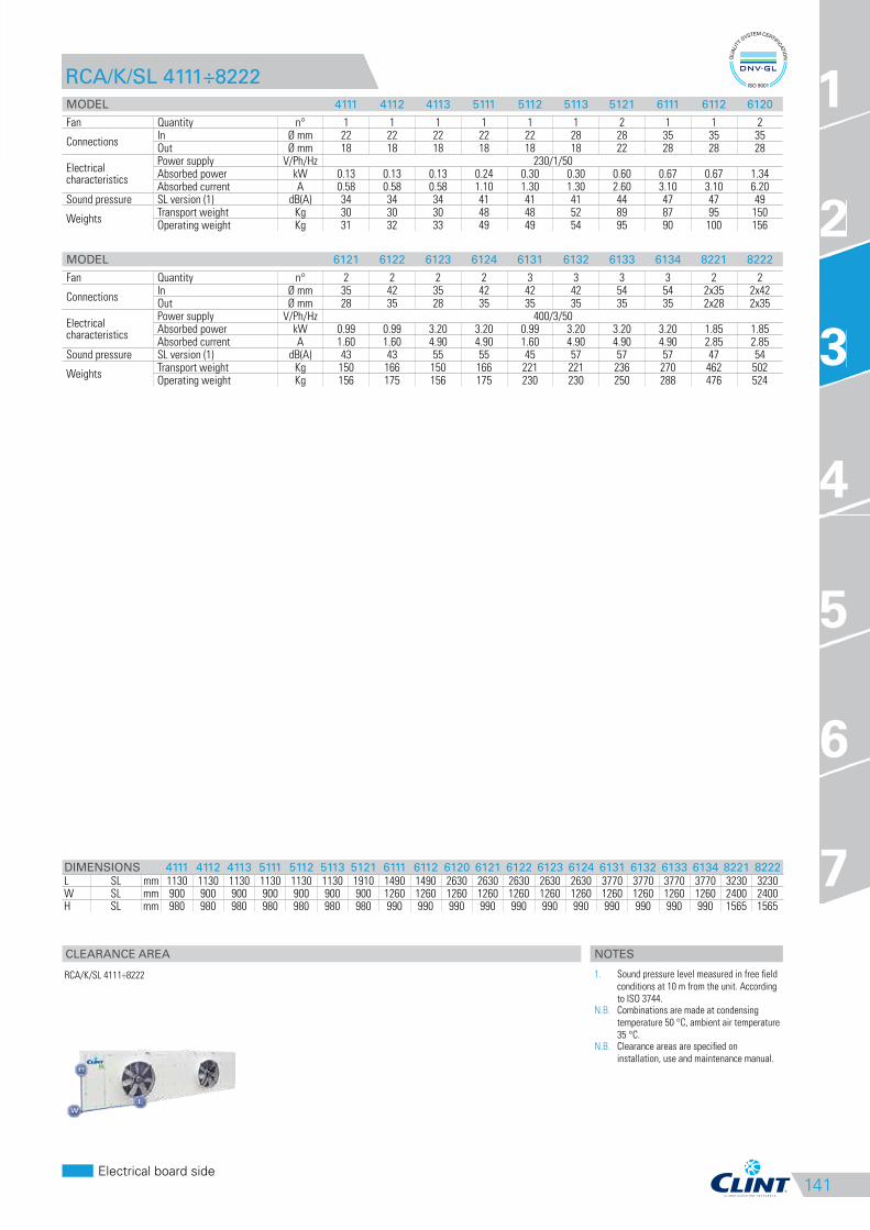
RCA/K/SL 4111÷8222
MODEL 4111 4112 4113 5111 5112 5113 5121 6111 6112 6120
Fan Quantity n° 1 1 1 1 1 1 2 1 1 2
ConnectionsIn Ø mm 22 22 22 22 22 28 28 35 35 35Out Ø mm 18 18 18 18 18 18 22 28 28 28
Electrical characteristics
Power supply V/Ph/Hz 230/1/50Absorbed power kW 0.13 0.13 0.13 0.24 0.30 0.30 0.60 0.67 0.67 1.34Absorbed current A 0.58 0.58 0.58 1.10 1.30 1.30 2.60 3.10 3.10 6.20
Sound pressure SL version (1) dB(A) 34 34 34 41 41 41 44 47 47 49
WeightsTransport weight Kg 30 30 30 48 48 52 89 87 95 150Operating weight Kg 31 32 33 49 49 54 95 90 100 156
MODEL 6121 6122 6123 6124 6131 6132 6133 6134 8221 8222
Fan Quantity n° 2 2 2 2 3 3 3 3 2 2
ConnectionsIn Ø mm 35 42 35 42 42 42 54 54 2x35 2x42Out Ø mm 28 35 28 35 35 35 35 35 2x28 2x35
Electrical characteristics
Power supply V/Ph/Hz 400/3/50Absorbed power kW 0.99 0.99 3.20 3.20 0.99 3.20 3.20 3.20 1.85 1.85Absorbed current A 1.60 1.60 4.90 4.90 1.60 4.90 4.90 4.90 2.85 2.85
Sound pressure SL version (1) dB(A) 43 43 55 55 45 57 57 57 47 54
WeightsTransport weight Kg 150 166 150 166 221 221 236 270 462 502Operating weight Kg 156 175 156 175 230 230 250 288 476 524
DIMENSIONS 4111 4112 4113 5111 5112 5113 5121 6111 6112 6120 6121 6122 6123 6124 6131 6132 6133 6134 8221 8222
L SL mm 1130 1130 1130 1130 1130 1130 1910 1490 1490 2630 2630 2630 2630 2630 3770 3770 3770 3770 3230 3230W SL mm 900 900 900 900 900 900 900 1260 1260 1260 1260 1260 1260 1260 1260 1260 1260 1260 2400 2400H SL mm 980 980 980 980 980 980 980 990 990 990 990 990 990 990 990 990 990 990 1565 1565
3
RCA/K/SL 4111÷8222
NOTES
1. Sound pressure level measured in free field
conditions at 10 m from the unit. According
to ISO 3744.N.B. Combinations are made at condensing
temperature 50 °C, ambient air temperature
35 °C.N.B. Clearance areas are specified on
installation, use and maintenance manual.
142
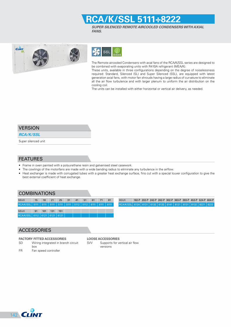
RCA/K/SSL 5111÷8222
SUPER SILENCED REMOTE AIRCOOLED CONDENSERS WITH AXIAL
FANS.
The Remote aircooled Condensers with axial fans of the RCA/K/SSL series are designed to
be combined with evaporating units with R410A refrigerant (MEA/K).
These units, available in three configurations depending on the degree of noiselessness
required: Standard, Silenced (SL) and Super Silenced (SSL), are equipped with latest
generation axial fans, with motor fan shrouds having a large radius of curvature to eliminate
all the air flow turbulence and with larger plenum to uniform the air distribution on the
cooling coil.
The units can be installed with either horizontal or vertical air delivery, as needed.
VERSION
RCA/K/SSL
Super silenced unit
FEATURES
• Frame in oven painted with a polyurethane resin and galvanised steel casework.
• The cowlings of the motorfans are made with a wide bending radius to eliminate any turbulence in the airflow.
• Heat exchanger is made with corrugated tubes with a greater heat exchange surface, fins cut with a special louver configuration to give the
best external coefficient of heat exchange.
COMBINATIONS
MEA/K 15 18 21 25 31 41 51 61 71 81
RCA/K/SSL 5111 5111 5111 5111 5111 5112 5112 6111 6111 6111
MEA/K 91 101 131 151
RCA/K/SSL 6112 6121 6121 6121
MEA/K 182-P 202-P 242-P 262-P 302-P 363-P 393-P 453-P 524-P 604-P
RCA/K/SSL 6124 6131 6132 6133 6141 8121 8131 8132 8221 8222
ACCESSORIES
FACTORY FITTED ACCESSORIES
SD Wiring integrated in branch circuit
box
FR Fan speed controller
LOOSE ACCESSORIES
SVV Supports for vertical air flow
versions

143
CLEARANCE AREA
Electrical board side
1
2
3
4
5
6
7
RCA/K/SSL 5111÷8222
MODEL 5111 5112 6111 6112 6121 6124 6131 6132
Fan Quantity n° 1 1 1 1 2 2 3 3
ConnectionsIn Ø mm 22 28 28 35 35 42 42 42Out Ø mm 18 18 22 28 28 35 35 35
Electrical characteristics
Power supply V/Ph/Hz 230/1/50 400/3/50Absorbed power kW 0.13 0.14 0.33 0.33 0.66 0.99 0.99 0.99Absorbed current A 0.59 0.68 1.60 1.60 3.20 1.60 1.60 1.60
Sound pressure SSL version (1) dB(A) 34 34 39 39 41 42 36 44
WeightsTransport weight Kg 48 52 79 95 150 166 221 221Operating weight Kg 49 54 82 98 156 175 230 230
MODEL 6133 6141 8121 8131 8132 8221 8222
Fan Quantity n° 3 4 2 3 3 4 4
ConnectionsIn Ø mm 54 35 42 42 54 2x35 2x35Out Ø mm 35 28 35 35 42 2x28 2x28
Electrical characteristics
Power supply V/Ph/Hz 400/3/50Absorbed power kW 0.99 0.99 0.84 0.84 0.84 0.84 1.85Absorbed current A 1.60 1.60 1.40 1.40 1.40 1.40 2.85
Sound pressure SSL version (1) dB(A) 44 45 43 45 45 45 54
WeightsTransport weight Kg 236 292 324 413 447 462 462Operating weight Kg 250 304 340 425 465 476 484
DIMENSIONS 5111 5112 6111 6112 6121 6124 6131 6132 6133 6141 8121 8131 8132 8221 8222
L SSL mm 1130 1130 1490 1490 2630 2630 3770 3770 3770 4910 3230 4580 4580 3230 3230W SSL mm 900 900 1260 1260 1260 1260 1260 1260 1260 1260 1380 1380 1380 2400 2400H SSL mm 980 980 990 990 990 990 990 990 990 990 1565 1565 1565 1565 1565
3
RCA/K/SSL 5111÷8222
NOTES
1. Sound pressure level measured in free field
conditions at 10 m from the unit. According
to ISO 3744.N.B. Combinations are made at condensing
temperature 50 °C, ambient air temperature
35 °C.N.B. Clearance areas are specified on
installation, use and maintenance manual.
144
ISB BACnet MSTP protocol, RS485
serial interface
ISBT BACnet TCP/IP protocol, Ethernet
port
ISL LonWorks protocol, FFT-10 serial
interface
IAV Remote set-point, 0-10 V signal
IAA Remote set-point, 4-20 mA signal
IAS Remote signal for second set-point
activation
IDL Demand limit from digital input
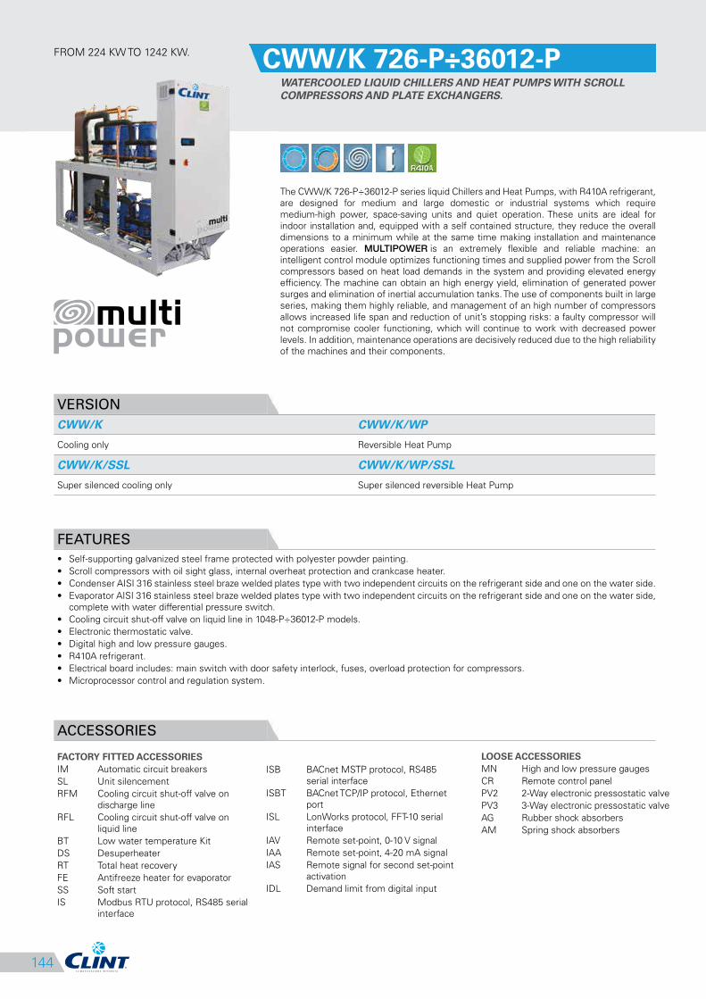
FROM 224 KW TO 1242 KW.CWW/K 726-P÷36012-P
WATERCOOLED LIQUID CHILLERS AND HEAT PUMPS WITH SCROLL
COMPRESSORS AND PLATE EXCHANGERS.
The CWW/K 726-P÷36012-P series liquid Chillers and Heat Pumps, with R410A refrigerant,
are designed for medium and large domestic or industrial systems which require
medium-high power, space-saving units and quiet operation. These units are ideal for
indoor installation and, equipped with a self contained structure, they reduce the overall
dimensions to a minimum while at the same time making installation and maintenance
operations easier. MULTIPOWER is an extremely flexible and reliable machine: an
intelligent control module optimizes functioning times and supplied power from the Scroll
compressors based on heat load demands in the system and providing elevated energy
efficiency. The machine can obtain an high energy yield, elimination of generated power
surges and elimination of inertial accumulation tanks. The use of components built in large
series, making them highly reliable, and management of an high number of compressors
allows increased life span and reduction of unit’s stopping risks: a faulty compressor will
not compromise cooler functioning, which will continue to work with decreased power
levels. In addition, maintenance operations are decisively reduced due to the high reliability
of the machines and their components.
VERSION
CWW/K CWW/K/WP
Cooling only Reversible Heat Pump
CWW/K/SSL CWW/K/WP/SSL
Super silenced cooling only Super silenced reversible Heat Pump
FEATURES
• Self-supporting galvanized steel frame protected with polyester powder painting.
• Scroll compressors with oil sight glass, internal overheat protection and crankcase heater.
• Condenser AISI 316 stainless steel braze welded plates type with two independent circuits on the refrigerant side and one on the water side.
• Evaporator AISI 316 stainless steel braze welded plates type with two independent circuits on the refrigerant side and one on the water side,
complete with water differential pressure switch.
• Cooling circuit shut-off valve on liquid line in 1048-P÷36012-P models.
• Electronic thermostatic valve.
• Digital high and low pressure gauges.
• R410A refrigerant.
• Electrical board includes: main switch with door safety interlock, fuses, overload protection for compressors.
• Microprocessor control and regulation system.
ACCESSORIES
FACTORY FITTED ACCESSORIES
IM Automatic circuit breakers
SL Unit silencement
RFM Cooling circuit shut-off valve on
discharge line
RFL Cooling circuit shut-off valve on
liquid line
BT Low water temperature Kit
DS Desuperheater
RT Total heat recovery
FE Antifreeze heater for evaporator
SS Soft start
IS Modbus RTU protocol, RS485 serial
interface
LOOSE ACCESSORIES
MN High and low pressure gauges
CR Remote control panel
PV2 2-Way electronic pressostatic valve
PV3 3-Way electronic pressostatic valve
AG Rubber shock absorbers
AM Spring shock absorbers

145
CLEARANCE AREA
Electrical board side
1
2
3
4
5
6
7
CWW/K 726-P÷36012-P
MODEL 726-P 786-P 826-P 906-P 1048-P 1128-P 1208-P 13010-P 15010-P
CoolingCooling capacity (1) kW 224 250 274 308 345 383 422 462 509Absorbed power (1) kW 52 57 63 70 78 86 95 104 115EER (1) 4.31 4.39 4.35 4.40 4.42 4.45 4.44 4.44 4.43
Cooling (EN14511)
Cooling capacity (1) kW 223 249 273 307 343 382 420 460 507Absorbed power (1) kW 55 60 66 74 82 90 99 109 121EER (1) 4.08 4.16 4.11 4.17 4.20 4.26 4.23 4.21 4.20ESEER 5.16 5.27 5.25 5.45 5.26 5.51 5.57 5.23 5.57
HeatingHeating capacity (2) kW 290 320 349 394 437 484 534 584 640Absorbed power (2) kW 66 74 80 88 101 111 119 135 144COP (2) 4.39 4.32 4.36 4.48 4.33 4.36 4.49 4.33 4.44
Heating (EN14511)
Heating capacity (2) kW 263 290 316 356 395 437 481 528 578Absorbed power (2) kW 68 79 83 91 104 114 123 140 149COP (2) 3.85 3.66 3.80 3.90 3.78 3.83 3.92 3.78 3.88SCOP (3) 4.98 5.11 5.25 5.23 5.39 5.33 5.23 5.47 5.24Energy Efficiency (3) % 191 196 202 201 208 205 201 211 202
CompressorQuantity n° 3+3 3+3 3+3 3+3 4+4 4+4 4+4 5+5 5+5Refrigerant circuits n° 2 2 2 2 2 2 2 2 2Capacity steps n° 6 8
EvaporatorWater flow l/s 10.70 11.94 13.09 14.72 16.48 18.30 20.16 22.07 24.32Pressure drops kPa 54 51 56 56 60 47 52 60 57Water connections DN 80 80 80 80 80 80 80 80 80
CondenserWater flow l/s 13.19 14.67 16.10 18.06 20.21 22.41 24.70 27.04 29.81Pressure drops kPa 70 74 81 76 67 59 65 75 76Water connections DN 80 80 80 80 80 80 80 80 80
Electrical characteristicsPower supply V/Ph/Hz 400/3/50Max. running current A 136 151 163 176 201 218 234 251 293Max. starting current A 261 284 331 344 334 385 402 384 461
Sound pressureSTD version (4) dB(A) 62 64 65 65 65 66 66 66 67With SL accessory (4) dB(A) 58 60 61 61 61 62 62 62 63SSL version (4) dB(A) 55 56 57 57 57 58 58 58 59
WeightsTransport weight Kg 1047 1103 1123 1159 1352 1422 1442 1642 1730Operating weight Kg 1080 1140 1160 1200 1400 1480 1500 1700 1800
MODEL 16812-P 18012-P 21012-P 24012-P 27012-P 30012-P 33012-P 36012-P
CoolingCooling capacity (1) kW 562 622 696 786 895 1015 1129 1242Absorbed power (1) kW 129 144 157 176 204 230 261 287EER (1) 4.36 4.32 4.43 4.47 4.39 4.41 4.33 4.33
Cooling (EN14511)
Cooling capacity (1) kW 559 619 693 783 891 1011 1124 1236Absorbed power (1) kW 135 151 164 183 213 239 273 301EER (1) 4.13 4.11 4.24 4.29 4.18 4.22 4.12 4.11ESEER 5.30 5.38 4.56 4.70 4.39 4.49 4.26 4.10
HeatingHeating capacity (2) kW 710 783 874 986 1113 1255 1391 1531Absorbed power (2) kW 164 181 203 224 259 289 321 357COP (2) 4.33 4.33 4.31 4.40 4.30 4.34 4.33 4.29
Heating (EN14511)
Heating capacity (2) kW 642 707 789 890 1005 1133 1258 1385Absorbed power (2) kW 170 187 209 230 267 297 331 368COP (2) 3.78 3.78 3.78 3.87 3.77 3.81 3.80 3.76SCOP (3) - - - - - - - -Energy Efficiency (3) % - - - - - - - -
CompressorQuantity n° 6+6 6+6 6+6 6+6 6+6 6+6 6+6 6+6Refrigerant circuits n° 2 2 2 2 2 2 2 2Capacity steps n° 10
EvaporatorWater flow l/s 26.85 29.72 33.25 37.55 42.76 48.49 53.94 59.34Pressure drops kPa 70 59 60 53 66 61 70 79Water connections DN 80 80 150 150 150 150 150 150
CondenserWater flow l/s 33.01 36.60 40.75 45.98 52.51 59.48 66.41 73.05Pressure drops kPa 70 77 60 53 65 61 70 78Water connections DN 80 80 150 150 150 150 150 150
Electrical characteristicsPower supply V/Ph/Hz 400/3/50Max. running current A 326 352 399 454 506 559 629 699Max. starting current A 494 519 576 631 720 773 891 961
Sound pressureSTD version (4) dB(A) 67 68 71 72 73 73 74 74With SL accessory (4) dB(A) 63 63 67 68 69 69 70 70SSL version (4) dB(A) 59 59 63 64 65 65 66 66
WeightsTransport weight Kg 1930 1968 2806 2884 3184 3558 3658 3708Operating weight Kg 2000 2050 2900 3000 3300 3700 3800 3850
DIMENSIONS 726-P 786-P 826-P 906-P 1048-P 1128-P 1208-P 13010-P 15010-P 16812-P 18012-P 21012-P 24012-P 27012-P 30012-P 33012-P 36012-P
L STD/SSL mm 2500 2500 2500 2500 3000 3000 3000 3550 3550 4000 4000 4650 4650 4650 4650 4650 4650W STD/SSL mm 800 800 800 800 800 800 800 800 800 800 800 1350 1350 1350 1350 1350 1350H STD/SSL mm 1900 1900 1900 1900 1900 1900 1900 1900 1900 1900 1900 1900 1900 1900 1900 1900 1900
3
CWW/K 726-P÷36012-P
500 500 800 500
NOTES
1. Chilled water from 12 to 7 °C, water temperature at the condenser from 30 to 35 °C.2. Heated water from 40 to 45 °C, water temperature at the evaporator from 15 to 10 °C.3. Seasonal energy efficiency of ambient heating at low temperature with average
climatic conditions. According to EU Regulation n. 811/2013.4. Sound pressure level measured in free field conditions at 1 m from the unit. According
to ISO 3744.N.B. Weights of SSL and WP versions are specified on technical brochure.
146
ISB BACnet MSTP protocol, RS485
serial interface
ISBT BACnet TCP/IP protocol, Ethernet
port
ISL LonWorks protocol, FFT-10 serial
interface
IAV Remote set-point, 0-10 V signal
IAA Remote set-point, 4-20 mA signal
IAS Remote signal for second set-point
activation
IDL Demand limit from digital input
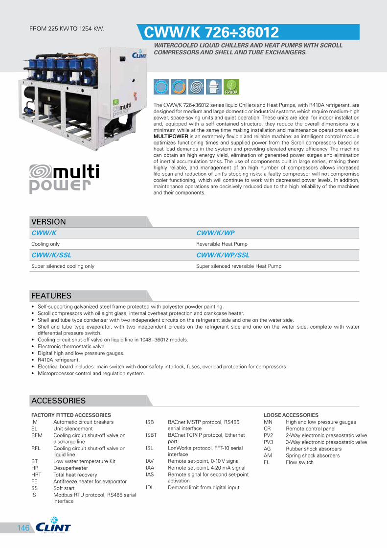
FROM 225 KW TO 1254 KW.CWW/K 726÷36012
WATERCOOLED LIQUID CHILLERS AND HEAT PUMPS WITH SCROLL
COMPRESSORS AND SHELL AND TUBE EXCHANGERS.
The CWW/K 726÷36012 series liquid Chillers and Heat Pumps, with R410A refrigerant, are
designed for medium and large domestic or industrial systems which require medium-high
power, space-saving units and quiet operation. These units are ideal for indoor installation
and, equipped with a self contained structure, they reduce the overall dimensions to a
minimum while at the same time making installation and maintenance operations easier.
MULTIPOWER is an extremely flexible and reliable machine: an intelligent control module
optimizes functioning times and supplied power from the Scroll compressors based on
heat load demands in the system and providing elevated energy efficiency. The machine
can obtain an high energy yield, elimination of generated power surges and elimination
of inertial accumulation tanks. The use of components built in large series, making them
highly reliable, and management of an high number of compressors allows increased
life span and reduction of unit’s stopping risks: a faulty compressor will not compromise
cooler functioning, which will continue to work with decreased power levels. In addition,
maintenance operations are decisively reduced due to the high reliability of the machines
and their components.
VERSION
CWW/K CWW/K/WP
Cooling only Reversible Heat Pump
CWW/K/SSL CWW/K/WP/SSL
Super silenced cooling only Super silenced reversible Heat Pump
FEATURES
• Self-supporting galvanized steel frame protected with polyester powder painting.
• Scroll compressors with oil sight glass, internal overheat protection and crankcase heater.
• Shell and tube type condenser with two independent circuits on the refrigerant side and one on the water side.
• Shell and tube type evaporator, with two independent circuits on the refrigerant side and one on the water side, complete with water
differential pressure switch.
• Cooling circuit shut-off valve on liquid line in 1048÷36012 models.
• Electronic thermostatic valve.
• Digital high and low pressure gauges.
• R410A refrigerant.
• Electrical board includes: main switch with door safety interlock, fuses, overload protection for compressors.
• Microprocessor control and regulation system.
ACCESSORIES
FACTORY FITTED ACCESSORIES
IM Automatic circuit breakers
SL Unit silencement
RFM Cooling circuit shut-off valve on
discharge line
RFL Cooling circuit shut-off valve on
liquid line
BT Low water temperature Kit
HR Desuperheater
HRT Total heat recovery
FE Antifreeze heater for evaporator
SS Soft start
IS Modbus RTU protocol, RS485 serial
interface
LOOSE ACCESSORIES
MN High and low pressure gauges
CR Remote control panel
PV2 2-Way electronic pressostatic valve
PV3 3-Way electronic pressostatic valve
AG Rubber shock absorbers
AM Spring shock absorbers
FL Flow switch
147
CLEARANCE AREA
Electrical board side
1
2
3
4
5
6
7
CWW/K 726÷36012
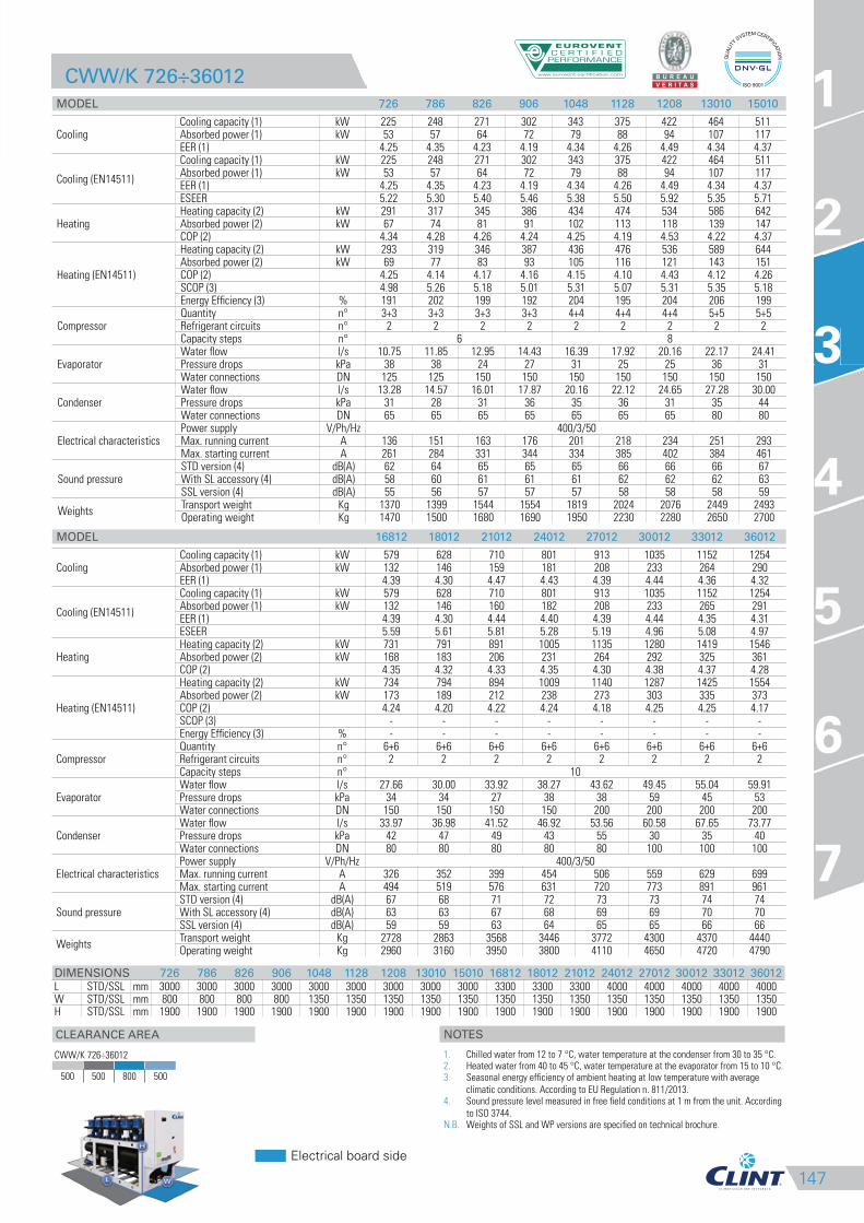
MODEL 726 786 826 906 1048 1128 1208 13010 15010
CoolingCooling capacity (1) kW 225 248 271 302 343 375 422 464 511Absorbed power (1) kW 53 57 64 72 79 88 94 107 117EER (1) 4.25 4.35 4.23 4.19 4.34 4.26 4.49 4.34 4.37
Cooling (EN14511)
Cooling capacity (1) kW 225 248 271 302 343 375 422 464 511Absorbed power (1) kW 53 57 64 72 79 88 94 107 117EER (1) 4.25 4.35 4.23 4.19 4.34 4.26 4.49 4.34 4.37ESEER 5.22 5.30 5.40 5.46 5.38 5.50 5.92 5.35 5.71
HeatingHeating capacity (2) kW 291 317 345 386 434 474 534 586 642Absorbed power (2) kW 67 74 81 91 102 113 118 139 147COP (2) 4.34 4.28 4.26 4.24 4.25 4.19 4.53 4.22 4.37
Heating (EN14511)
Heating capacity (2) kW 293 319 346 387 436 476 536 589 644Absorbed power (2) kW 69 77 83 93 105 116 121 143 151COP (2) 4.25 4.14 4.17 4.16 4.15 4.10 4.43 4.12 4.26SCOP (3) 4.98 5.26 5.18 5.01 5.31 5.07 5.31 5.35 5.18Energy Efficiency (3) % 191 202 199 192 204 195 204 206 199
CompressorQuantity n° 3+3 3+3 3+3 3+3 4+4 4+4 4+4 5+5 5+5Refrigerant circuits n° 2 2 2 2 2 2 2 2 2Capacity steps n° 6 8
EvaporatorWater flow l/s 10.75 11.85 12.95 14.43 16.39 17.92 20.16 22.17 24.41Pressure drops kPa 38 38 24 27 31 25 25 36 31Water connections DN 125 125 150 150 150 150 150 150 150
CondenserWater flow l/s 13.28 14.57 16.01 17.87 20.16 22.12 24.65 27.28 30.00Pressure drops kPa 31 28 31 36 35 36 31 35 44Water connections DN 65 65 65 65 65 65 65 80 80
Electrical characteristicsPower supply V/Ph/Hz 400/3/50Max. running current A 136 151 163 176 201 218 234 251 293Max. starting current A 261 284 331 344 334 385 402 384 461
Sound pressureSTD version (4) dB(A) 62 64 65 65 65 66 66 66 67With SL accessory (4) dB(A) 58 60 61 61 61 62 62 62 63SSL version (4) dB(A) 55 56 57 57 57 58 58 58 59
WeightsTransport weight Kg 1370 1399 1544 1554 1819 2024 2076 2449 2493Operating weight Kg 1470 1500 1680 1690 1950 2230 2280 2650 2700
MODEL 16812 18012 21012 24012 27012 30012 33012 36012
CoolingCooling capacity (1) kW 579 628 710 801 913 1035 1152 1254Absorbed power (1) kW 132 146 159 181 208 233 264 290EER (1) 4.39 4.30 4.47 4.43 4.39 4.44 4.36 4.32
Cooling (EN14511)
Cooling capacity (1) kW 579 628 710 801 913 1035 1152 1254Absorbed power (1) kW 132 146 160 182 208 233 265 291EER (1) 4.39 4.30 4.44 4.40 4.39 4.44 4.35 4.31ESEER 5.59 5.61 5.81 5.28 5.19 4.96 5.08 4.97
HeatingHeating capacity (2) kW 731 791 891 1005 1135 1280 1419 1546Absorbed power (2) kW 168 183 206 231 264 292 325 361COP (2) 4.35 4.32 4.33 4.35 4.30 4.38 4.37 4.28
Heating (EN14511)
Heating capacity (2) kW 734 794 894 1009 1140 1287 1425 1554Absorbed power (2) kW 173 189 212 238 273 303 335 373COP (2) 4.24 4.20 4.22 4.24 4.18 4.25 4.25 4.17SCOP (3) - - - - - - - -Energy Efficiency (3) % - - - - - - - -
CompressorQuantity n° 6+6 6+6 6+6 6+6 6+6 6+6 6+6 6+6Refrigerant circuits n° 2 2 2 2 2 2 2 2Capacity steps n° 10
EvaporatorWater flow l/s 27.66 30.00 33.92 38.27 43.62 49.45 55.04 59.91Pressure drops kPa 34 34 27 38 38 59 45 53Water connections DN 150 150 150 150 200 200 200 200
CondenserWater flow l/s 33.97 36.98 41.52 46.92 53.56 60.58 67.65 73.77Pressure drops kPa 42 47 49 43 55 30 35 40Water connections DN 80 80 80 80 80 100 100 100
Electrical characteristicsPower supply V/Ph/Hz 400/3/50Max. running current A 326 352 399 454 506 559 629 699Max. starting current A 494 519 576 631 720 773 891 961
Sound pressureSTD version (4) dB(A) 67 68 71 72 73 73 74 74With SL accessory (4) dB(A) 63 63 67 68 69 69 70 70SSL version (4) dB(A) 59 59 63 64 65 65 66 66
WeightsTransport weight Kg 2728 2863 3568 3446 3772 4300 4370 4440Operating weight Kg 2960 3160 3950 3800 4110 4650 4720 4790
DIMENSIONS 726 786 826 906 1048 1128 1208 13010 15010 16812 18012 21012 24012 27012 30012 33012 36012
L STD/SSL mm 3000 3000 3000 3000 3000 3000 3000 3000 3000 3300 3300 3300 4000 4000 4000 4000 4000W STD/SSL mm 800 800 800 800 1350 1350 1350 1350 1350 1350 1350 1350 1350 1350 1350 1350 1350H STD/SSL mm 1900 1900 1900 1900 1900 1900 1900 1900 1900 1900 1900 1900 1900 1900 1900 1900 1900
3
CWW/K 726÷36012
500 500 800 500
NOTES
1. Chilled water from 12 to 7 °C, water temperature at the condenser from 30 to 35 °C.2. Heated water from 40 to 45 °C, water temperature at the evaporator from 15 to 10 °C.3. Seasonal energy efficiency of ambient heating at low temperature with average
climatic conditions. According to EU Regulation n. 811/2013.4. Sound pressure level measured in free field conditions at 1 m from the unit. According
to ISO 3744.N.B. Weights of SSL and WP versions are specified on technical brochure.
148
ISB BACnet MSTP protocol, RS485
serial interface
ISBT BACnet TCP/IP protocol, Ethernet
port
ISL LonWorks protocol, FFT-10 serial
interface
IAV Remote set-point, 0-10 V signal
IAA Remote set-point, 4-20 mA signal
IAS Remote signal for second set-point
activation
IDL Demand limit from digital input
CP Potential free contacts
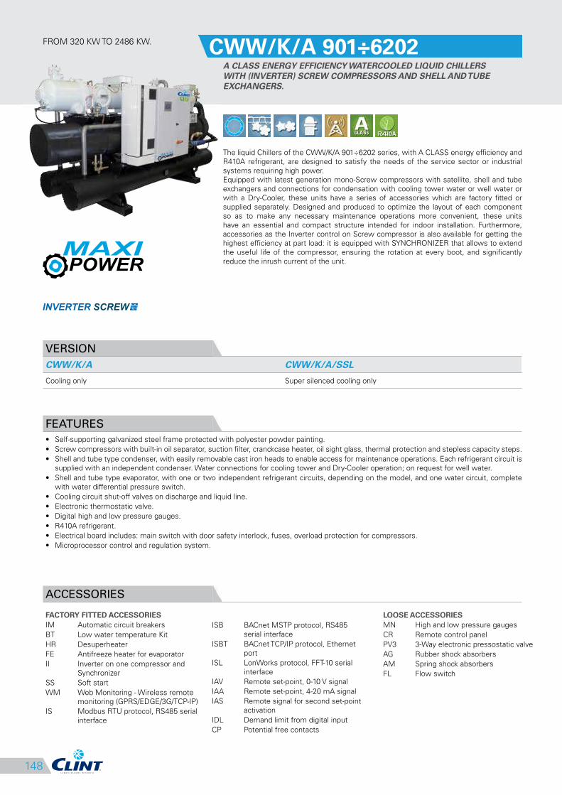
FROM 320 KW TO 2486 KW.CWW/K/A 901÷6202
A CLASS ENERGY EFFICIENCY WATERCOOLED LIQUID CHILLERS
WITH (INVERTER) SCREW COMPRESSORS AND SHELL AND TUBE
EXCHANGERS.
The liquid Chillers of the CWW/K/A 901÷6202 series, with A CLASS energy efficiency and
R410A refrigerant, are designed to satisfy the needs of the service sector or industrial
systems requiring high power.
Equipped with latest generation mono-Screw compressors with satellite, shell and tube
exchangers and connections for condensation with cooling tower water or well water or
with a Dry-Cooler, these units have a series of accessories which are factory fitted or
supplied separately. Designed and produced to optimize the layout of each component
so as to make any necessary maintenance operations more convenient, these units
have an essential and compact structure intended for indoor installation. Furthermore,
accessories as the Inverter control on Screw compressor is also available for getting the
highest efficiency at part load: it is equipped with SYNCHRONIZER that allows to extend
the useful life of the compressor, ensuring the rotation at every boot, and significantly
reduce the inrush current of the unit.
VERSION
CWW/K/A CWW/K/A/SSL
Cooling only Super silenced cooling only
FEATURES
• Self-supporting galvanized steel frame protected with polyester powder painting.
• Screw compressors with built-in oil separator, suction filter, cranckcase heater, oil sight glass, thermal protection and stepless capacity steps.
• Shell and tube type condenser, with easily removable cast iron heads to enable access for maintenance operations. Each refrigerant circuit is
supplied with an independent condenser. Water connections for cooling tower and Dry-Cooler operation; on request for well water.
• Shell and tube type evaporator, with one or two independent refrigerant circuits, depending on the model, and one water circuit, complete
with water differential pressure switch.
• Cooling circuit shut-off valves on discharge and liquid line.
• Electronic thermostatic valve.
• Digital high and low pressure gauges.
• R410A refrigerant.
• Electrical board includes: main switch with door safety interlock, fuses, overload protection for compressors.
• Microprocessor control and regulation system.
ACCESSORIES
FACTORY FITTED ACCESSORIES
IM Automatic circuit breakers
BT Low water temperature Kit
HR Desuperheater
FE Antifreeze heater for evaporator
II Inverter on one compressor and
Synchronizer
SS Soft start
WM Web Monitoring - Wireless remote
monitoring (GPRS/EDGE/3G/TCP-IP)
IS Modbus RTU protocol, RS485 serial
interface
LOOSE ACCESSORIES
MN High and low pressure gauges
CR Remote control panel
PV3 3-Way electronic pressostatic valve
AG Rubber shock absorbers
AM Spring shock absorbers
FL Flow switch

149
CLEARANCE AREA
Electrical board side
1
2
3
4
5
6
7
CWW/K/A 901÷6202
MODEL 901 1101 1301 1501 1601 2001 2201 2401 2901 1902
CoolingCooling capacity (1) kW 320 387 466 508 566 699 792 880 1067 644Absorbed power (1) kW 62 75 90 98 109 135 152 171 207 125EER (1) 5.16 5.16 5.18 5.18 5.19 5.18 5.21 5.15 5.15 5.15
Cooling (EN14511)
Cooling capacity (1) kW 319 386 465 506 564 697 789 878 1064 642Absorbed power (1) kW 63 76 91 100 111 137 155 173 210 127EER (1) 5.06 5.08 5.11 5.06 5.08 5.09 5.09 5.08 5.07 5.06ESEER 5.34 5.41 5.38 5.35 5.52 5.75 5.72 5.63 5.61 5.36EUROVENT Class A A A A A A A A A A
CompressorQuantity n° 1 1 1 1 1 1 1 1 1 2Refrigerant circuits n° 1 1 1 1 1 1 1 1 1 2Capacity steps n° Stepless
EvaporatorWater flow l/s 15.29 18.49 22.26 24.27 27.04 33.40 37.84 42.04 50.98 30.77Pressure drops kPa 33 24 34 38 40 34 43 36 41 47Water connections DN 150 150 150 150 150 200 200 200 200 150
CondenserWater flow l/s 18.25 22.07 26.56 28.95 32.25 39.85 45.10 50.21 60.87 36.74Pressure drops kPa 22 22 25 30 29 32 35 37 31 22Water connections DN 100 125 125 125 125 150 150 150 150 100
Electrical characteristics
Power supply V/Ph/Hz 400/3/50Max. running current A 144 171 195 195 144 171 195 367 383 288Max. starting current A 288 288 288 288 288 288 288 656 656 432
Sound pressureSTD version (2) dB(A) 81 81 82 82 82 81 81 83 83 84SSL version (2) dB(A) 77 77 78 78 78 77 77 79 79 80
WeightsTransport weight Kg 2059 2431 2518 2558 2877 3298 3389 3984 4535 3884Operating weight Kg 2270 2760 2880 2920 3240 3890 3980 4710 5310 4380
MODEL 2202 2602 2902 3202 4002 4502 4802 5802 6202
CoolingCooling capacity (1) kW 781 895 1023 1138 1411 1584 1766 2142 2486Absorbed power (1) kW 152 173 196 219 271 301 337 404 474EER (1) 5.14 5.17 5.22 5.20 5.21 5.26 5.24 5.30 5.24
Cooling (EN14511)
Cooling capacity (1) kW 779 892 1019 1134 1405 1577 1758 2130 2472Absorbed power (1) kW 154 176 200 223 277 308 345 416 488EER (1) 5.06 5.07 5.10 5.09 5.07 5.12 5.10 5.12 5.07ESEER 5.44 5.40 5.41 5.58 5.80 5.81 5.68 5.50 5.41EUROVENT Class A A A A A A A A A
CompressorQuantity n° 2 2 2 2 2 2 2 2 2Refrigerant circuits n° 2 2 2 2 2 2 2 2 2Capacity steps n° Stepless
EvaporatorWater flow l/s 37.31 42.76 48.88 54.37 67.41 75.68 84.38 102.34 118.78Pressure drops kPa 32 48 53 49 49 57 62 63 72Water connections DN 200 200 200 200 250 250 250 250 250
CondenserWater flow l/s 44.58 51.03 58.24 64.83 80.36 90.06 100.48 121.64 141.42Pressure drops kPa 22 31 57 52 51 54 55 62 61Water connections DN 125 125 100 125 125 125 150 150 150
Electrical characteristics
Power supply V/Ph/Hz 400/3/50Max. running current A 342 390 390 504 612 644 734 766 812Max. starting current A 459 483 483 707 761 777 1023 1039 1062
Sound pressureSTD version (2) dB(A) 83 84 84 84 84 84 85 86 87SSL version (2) dB(A) 79 80 80 80 80 80 81 82 83
WeightsTransport weight Kg 4432 4589 4618 5432 5843 6001 7496 8426 8712Operating weight Kg 5050 5200 5370 6200 6830 6960 8650 9940 10360
DIMENSIONS 901 1101 1301 1501 1601 2001 2201 2401 2901 1902 2202 2602 2902 3202 4002 4502 4802 5802 6202
L STD/SSL mm 3150 3350 3500 3500 3500 3700 3700 3750 3750 3700 3700 3700 4600 4600 4800 4800 4850 4850 4850W STD/SSL mm 1000 1200 1200 1200 1200 1350 1350 1450 1450 1250 1300 1300 1300 1400 1400 1400 1400 1400 1400H STD/SSL mm 1850 1950 1950 1950 1950 2050 2050 2200 2200 1900 2100 2100 2100 2200 2200 2200 2550 2550 2550
3
CWW/K/A 901÷6202
500 500 800 500
NOTES
1. Chilled water from 12 to 7 °C, water
temperature at the condenser from 30 to
35 °C.2. Sound pressure level measured in free field
conditions at 1 m from the unit. According
to ISO 3744.N.B. Weights of SSL version are specified on
technical brochure.
150
ISBT BACnet TCP/IP protocol, Ethernet
port
ISL LonWorks protocol, FFT-10 serial
interface
IAV Remote set-point, 0-10 V signal
IAA Remote set-point, 4-20 mA signal
IAS Remote signal for second set-point
activation
IDL Demand limit from digital input
CP Potential free contacts
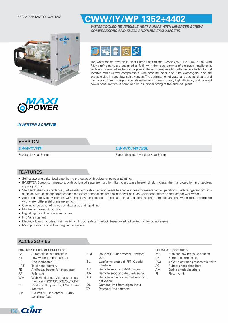
FROM 386 KW TO 1439 KW.CWW/IY/WP 1352÷4402
WATERCOOLED REVERSIBLE HEAT PUMPS WITH INVERTER SCREW
COMPRESSORS AND SHELL AND TUBE EXCHANGERS.
The watercooled reversibile Heat Pump units of the CWW/IY/WP 1352÷4402 line, with
R134a refrigerant, are designed to fulfill with the requirements of big sizes installations,
such as commercial and industrial plants. The units are provided with the new technological
Inverter mono-Screw compressors with satellite, shell and tube exchangers, and are
available also in super low noise version. The optimisation of water and cooling circuits and
the Inverter Screw compressors allow the units to reach a very high efficiency and reduced
power consumption, if combined with a proper sizing of the end-user plant.
VERSION
CWW/IY/WP CWW/IY/WP/SSL
Reversible Heat Pump Super silenced reversible Heat Pump
FEATURES
• Self-supporting galvanized steel frame protected with polyester powder painting.
• INVERTER Screw compressors, with built-in oil separator, suction filter, cranckcase heater, oil sight glass, thermal protection and stepless
capacity steps.
• Shell and tube type condenser, with easily removable cast iron heads to enable access for maintenance operations. Each refrigerant circuit is
supplied with an independent condenser. Water connections for cooling tower and Dry-Cooler operation; on request for well water.
• Shell and tube type evaporator, with one or two independent refrigerant circuits, depending on the model, and one water circuit, complete
with water differential pressure switch.
• Cooling circuit shut-off valves on discharge and liquid line.
• Electronic thermostatic valve.
• Digital high and low pressure gauges.
• R134a refrigerant.
• Electrical board includes: main switch with door safety interlock, fuses, overload protection for compressors.
• Microprocessor control and regulation system.
ACCESSORIES
FACTORY FITTED ACCESSORIES
IM Automatic circuit breakers
BT Low water temperature Kit
HR Desuperheater
HRT Total heat recovery
FE Antifreeze heater for evaporator
SS Soft start
WM Web Monitoring - Wireless remote
monitoring (GPRS/EDGE/3G/TCP-IP)
IS Modbus RTU protocol, RS485 serial
interface
ISB BACnet MSTP protocol, RS485
serial interface
LOOSE ACCESSORIES
MN High and low pressure gauges
CR Remote control panel
PV3 3-Way electronic pressostatic valve
AG Rubber shock absorbers
AM Spring shock absorbers
FL Flow switch
151
CLEARANCE AREA
Electrical board side
1
2
3
4
5
6
7
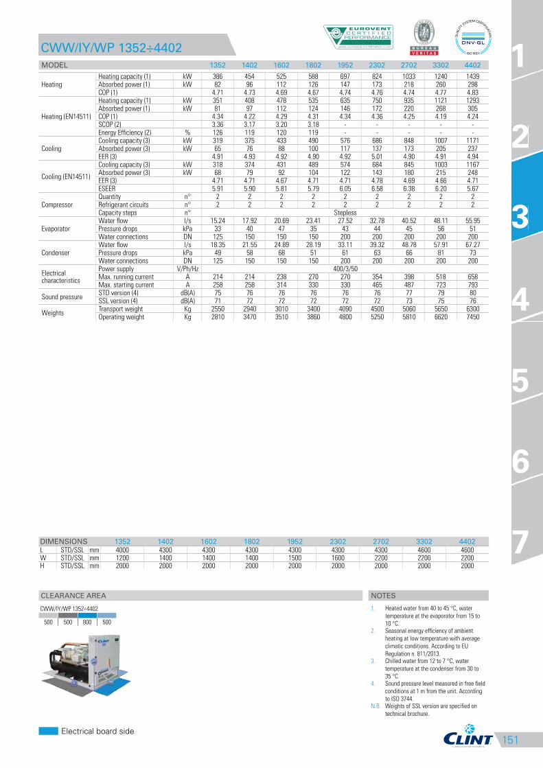
CWW/IY/WP 1352÷4402
MODEL 1352 1402 1602 1802 1952 2302 2702 3302 4402
HeatingHeating capacity (1) kW 386 454 525 588 697 824 1033 1240 1439Absorbed power (1) kW 82 96 112 126 147 173 218 260 298COP (1) 4.71 4.73 4.69 4.67 4.74 4.76 4.74 4.77 4.83
Heating (EN14511)
Heating capacity (1) kW 351 408 478 535 635 750 935 1121 1293Absorbed power (1) kW 81 97 112 124 146 172 220 268 305COP (1) 4.34 4.22 4.29 4.31 4.34 4.36 4.25 4.19 4.24SCOP (2) 3.36 3.17 3.20 3.18 - - - - -Energy Efficiency (2) % 126 119 120 119 - - - - -
CoolingCooling capacity (3) kW 319 375 433 490 576 686 848 1007 1171Absorbed power (3) kW 65 76 88 100 117 137 173 205 237EER (3) 4.91 4.93 4.92 4.90 4.92 5.01 4.90 4.91 4.94
Cooling (EN14511)
Cooling capacity (3) kW 318 374 431 489 574 684 845 1003 1167Absorbed power (3) kW 68 79 92 104 122 143 180 215 248EER (3) 4.71 4.71 4.67 4.71 4.71 4.78 4.69 4.66 4.71ESEER 5.91 5.90 5.81 5.79 6.05 6.58 6.38 6.20 5.67
CompressorQuantity n° 2 2 2 2 2 2 2 2 2Refrigerant circuits n° 2 2 2 2 2 2 2 2 2Capacity steps n° Stepless
EvaporatorWater flow l/s 15.24 17.92 20.69 23.41 27.52 32.78 40.52 48.11 55.95Pressure drops kPa 33 40 47 35 43 44 45 56 51Water connections DN 125 150 150 150 200 200 200 200 200
CondenserWater flow l/s 18.35 21.55 24.89 28.19 33.11 39.32 48.78 57.91 67.27Pressure drops kPa 49 58 68 51 61 63 66 81 73Water connections DN 125 150 150 150 200 200 200 200 200
Electrical characteristics
Power supply V/Ph/Hz 400/3/50Max. running current A 214 214 238 270 270 354 398 518 658Max. starting current A 258 258 314 330 330 465 487 723 793
Sound pressureSTD version (4) dB(A) 75 76 76 76 76 76 77 79 80SSL version (4) dB(A) 71 72 72 72 72 72 73 75 76
WeightsTransport weight Kg 2550 2940 3010 3400 4090 4500 5060 5650 6300Operating weight Kg 2810 3470 3510 3860 4800 5250 5810 6620 7450
DIMENSIONS 1352 1402 1602 1802 1952 2302 2702 3302 4402
L STD/SSL mm 4000 4300 4300 4300 4300 4300 4300 4600 4600W STD/SSL mm 1200 1400 1400 1400 1500 1600 2200 2200 2200H STD/SSL mm 2000 2000 2000 2000 2000 2000 2000 2000 2000
3
CWW/IY/WP 1352÷4402
500 500 800 500
NOTES
1. Heated water from 40 to 45 °C, water
temperature at the evaporator from 15 to
10 °C.2. Seasonal energy efficiency of ambient
heating at low temperature with average
climatic conditions. According to EU
Regulation n. 811/2013.3. Chilled water from 12 to 7 °C, water
temperature at the condenser from 30 to
35 °C.4. Sound pressure level measured in free field
conditions at 1 m from the unit. According
to ISO 3744.N.B. Weights of SSL version are specified on
technical brochure.
152
ISB BACnet MSTP protocol, RS485
serial interface
ISBT BACnet TCP/IP protocol, Ethernet
port
ISL LonWorks protocol, FFT-10 serial
interface
IAV Remote set-point, 0-10 V signal
IAA Remote set-point, 4-20 mA signal
IAS Remote signal for second set-point
activation
IDL Demand limit from digital input
CP Potential free contacts
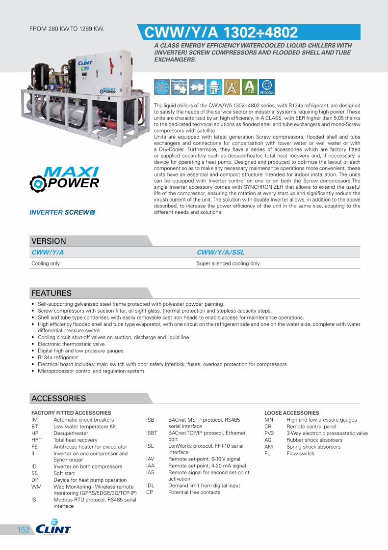
FROM 280 KW TO 1289 KW.CWW/Y/A 1302÷4802
A CLASS ENERGY EFFICIENCY WATERCOOLED LIQUID CHILLERS WITH
(INVERTER) SCREW COMPRESSORS AND FLOODED SHELL AND TUBE
EXCHANGERS.
The liquid chillers of the CWW/Y/A 1302÷4802 series, with R134a refrigerant, are designed
to satisfy the needs of the service sector or industrial systems requiring high power. These
units are characterized by an high efficiency, in A CLASS, with EER higher than 5,05 thanks
to the dedicated technical solutions as flooded shell and tube exchangers and mono-Screw
compressors with satellite.
Units are equipped with latest generation Screw compressors, flooded shell and tube
exchangers and connections for condensation with tower water or well water or with
a Dry-Cooler. Furthermore, they have a series of accessories which are factory fitted
or supplied separately such as desuperheater, total heat recovery and, if neccessary, a
device for operating a heat pump. Designed and produced to optimize the layout of each
component so as to make any necessary maintenance operations more convenient, these
units have an essential and compact structure intended for indoor installation. The units
can be equipped with Inverter control on one or on both the Screw compressors.The
single Inverter accessory comes with SYNCHRONIZER that allows to extend the useful
life of the compressor, ensuring the rotation at every start up and significantly reduce the
inrush current of the unit. The solution with double Inverter allows, in addition to the above
described, to increase the power efficiency of the unit in the same size, adapting to the
different needs and solutions.
VERSION
CWW/Y/A CWW/Y/A/SSL
Cooling only Super silenced cooling only
FEATURES
• Self-supporting galvanized steel frame protected with polyester powder painting.
• Screw compressors with suction filter, oil sight glass, thermal protection and stepless capacity steps.
• Shell and tube type condenser, with easily removable cast iron heads to enable access for maintenance operations.
• High efficiency flooded shell and tube type evaporator, with one circuit on the refrigerant side and one on the water side, complete with water
differential pressure switch.
• Cooling circuit shut-off valves on suction, discharge and liquid line.
• Electronic thermostatic valve.
• Digital high and low pressure gauges.
• R134a refrigerant.
• Electrical board includes: main switch with door safety interlock, fuses, overload protection for compressors.
• Microprocessor control and regulation system.
ACCESSORIES
FACTORY FITTED ACCESSORIES
IM Automatic circuit breakers
BT Low water temperature Kit
HR Desuperheater
HRT Total heat recovery
FE Antifreeze heater for evaporator
II Inverter on one compressor and
Synchronizer
ID Inverter on both compressors
SS Soft start
DP Device for heat pump operation
WM Web Monitoring - Wireless remote
monitoring (GPRS/EDGE/3G/TCP-IP)
IS Modbus RTU protocol, RS485 serial
interface
LOOSE ACCESSORIES
MN High and low pressure gauges
CR Remote control panel
PV3 3-Way electronic pressostatic valve
AG Rubber shock absorbers
AM Spring shock absorbers
FL Flow switch
153
CLEARANCE AREA
Electrical board side
1
2
3
4
5
6
7
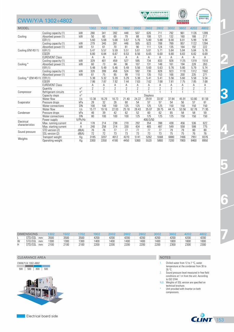
CWW/Y/A 1302÷4802
MODEL 1302 1502 1702 1902 2002 2602 2802 3002 3602 4202 4802
CoolingCooling capacity (1) kW 280 341 392 448 507 626 711 792 961 1126 1289Absorbed power (1) kW 50 60 69 79 88 108 121 132 160 188 217EER (1) 5.60 5.68 5.68 5.67 5.76 5.80 5.88 6.00 6.01 5.99 5.94
Cooling (EN14511)
Cooling capacity (1) kW 279 340 391 446 505 623 708 789 957 1122 1284Absorbed power (1) kW 51 61 70 81 90 111 124 135 164 192 222EER (1) 5.47 5.57 5.59 5.51 5.61 5.61 5.71 5.84 5.84 5.84 5.78ESEER 6.80 6.84 6.87 6.53 6.56 6.65 6.60 6.80 6.83 6.82 6.69EUROVENT Class A A A A A A A A A A A
Cooling *Cooling capacity (1) kW 329 401 459 527 595 734 833 928 1125 1319 1510Absorbed power (1) kW 60 73 84 96 107 131 148 161 194 228 263EER (1) 5.48 5.49 5.46 5.49 5.56 5.60 5.63 5.76 5.80 5.79 5.74
Cooling * (EN14511)
Cooling capacity (1) kW 328 399 458 524 592 730 828 923 1119 1312 1502Absorbed power (1) kW 61 75 85 99 110 135 153 166 200 235 271EER (1) 5.38 5.32 5.39 5.29 5.38 5.41 5.41 5.56 5.60 5.58 5.54ESEER 7.86 7.87 7.92 7.44 7.63 7.62 7.68 7.81 7.75 7.85 7.68EUROVENT Class A A A A A A A A A A A
CompressorQuantity n° 2 2 2 2 2 2 2 2 2 2 2Refrigerant circuits n° 1 1 1 1 1 1 1 1 1 1 1Capacity steps n° Stepless
EvaporatorWater flow l/s 13.38 16.29 18.73 21.40 24.22 29.91 33.97 37.84 45.91 53.80 61.59Pressure drops kPa 28 32 26 60 54 57 57 54 56 57 61Water connections DN 100 100 100 125 125 125 125 150 150 150 150
CondenserWater flow l/s 15.77 19.16 22.03 25.18 28.43 35.07 39.75 44.15 53.56 62.78 71.95Pressure drops kPa 46 39 42 62 52 60 62 65 58 58 59Water connections DN 80 100 100 100 125 125 125 125 150 150 150
Electrical characteristics
Power supply V/Ph/Hz 400/3/50Max. running current A 178 214 238 270 292 354 398 438 456 536 622Max. starting current A 240 258 314 330 434 465 487 549 558 598 775
Sound pressureSTD version (2) dB(A) 76 76 77 77 77 77 77 79 79 80 80SSL version (2) dB(A) 72 72 73 73 73 73 73 75 75 76 76
WeightsTransport weight Kg 3185 3207 4012 4270 5141 5262 5568 6880 7466 7951 8376Operating weight Kg 3300 3350 4180 4450 5360 5520 5860 7200 7900 8460 8950
DIMENSIONS 1302 1502 1702 1902 2002 2602 2802 3002 3602 4202 4802
L STD/SSL mm 3500 3500 3500 4200 4200 4200 4200 4200 4200 4200 4200W STD/SSL mm 1300 1300 1300 1400 1400 1400 1400 1400 1800 1800 1800H STD/SSL mm 2100 2100 2100 2200 2200 2200 2200 2200 2300 2300 2300
3
CWW/Y/A 1302÷4802
500 500 800 500
NOTES
1. Chilled water from 12 to 7 °C, water
temperature at the condenser from 30 to
35 °C.2. Sound pressure level measured in free field
conditions at 1 m from the unit. According
to ISO 3744.N.B. Weights of SSL version are specified on
technical brochure.* Unit provided with Inverter on both
compressors.
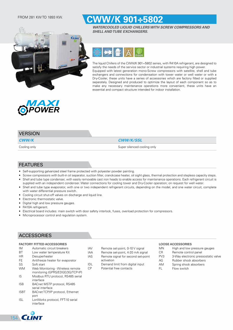
154
IAV Remote set-point, 0-10 V signal
IAA Remote set-point, 4-20 mA signal
IAS Remote signal for second set-point
activation
IDL Demand limit from digital input
CP Potential free contacts
FROM 281 KW TO 1893 KW.CWW/K 901÷5802
WATERCOOLED LIQUID CHILLERS WITH SCREW COMPRESSORS AND
SHELL AND TUBE EXCHANGERS.
The liquid Chillers of the CWW/K 901÷5802 series, with R410A refrigerant, are designed to
satisfy the needs of the service sector or industrial systems requiring high power.
Equipped with latest generation mono-Screw compressors with satellite, shell and tube
exchangers and connections for condensation with tower water or well water or with a
Dry-Cooler, these units have a series of accessories which are factory fitted or supplied
separately. Designed and produced to optimize the layout of each component so as to
make any necessary maintenance operations more convenient, these units have an
essential and compact structure intended for indoor installation.
VERSION
CWW/K CWW/K/SSL
Cooling only Super silenced cooling only
FEATURES
• Self-supporting galvanized steel frame protected with polyester powder painting.
• Screw compressors with built-in oil separator, suction filter, cranckcase heater, oil sight glass, thermal protection and stepless capacity steps.
• Shell and tube type condenser, with easily removable cast iron heads to enable access for maintenance operations. Each refrigerant circuit is
supplied with an independent condenser. Water connections for cooling tower and Dry-Cooler operation; on request for well water.
• Shell and tube type evaporator, with one or two independent refrigerant circuits, depending on the model, and one water circuit, complete
with water differential pressure switch.
• Cooling circuit shut-off valves on discharge and liquid line.
• Electronic thermostatic valve.
• Digital high and low pressure gauges.
• R410A refrigerant.
• Electrical board includes: main switch with door safety interlock, fuses, overload protection for compressors.
• Microprocessor control and regulation system.
ACCESSORIES
FACTORY FITTED ACCESSORIES
IM Automatic circuit breakers
BT Low water temperature Kit
HR Desuperheater
FE Antifreeze heater for evaporator
SS Soft start
WM Web Monitoring - Wireless remote
monitoring (GPRS/EDGE/3G/TCP-IP)
IS Modbus RTU protocol, RS485 serial
interface
ISB BACnet MSTP protocol, RS485
serial interface
ISBT BACnet TCP/IP protocol, Ethernet
port
ISL LonWorks protocol, FFT-10 serial
interface
LOOSE ACCESSORIES
MN High and low pressure gauges
CR Remote control panel
PV3 3-Way electronic pressostatic valve
AG Rubber shock absorbers
AM Spring shock absorbers
FL Flow switch
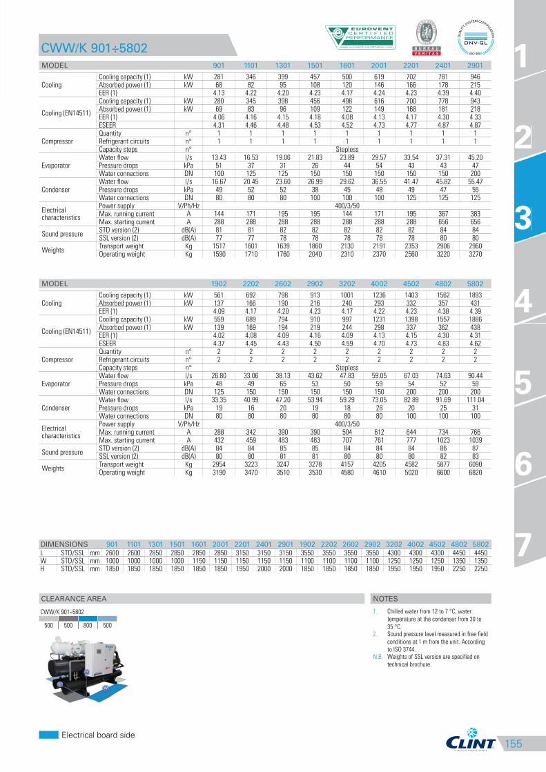
155
CLEARANCE AREA
Electrical board side
1
2
3
4
5
6
7
CWW/K 901÷5802
MODEL 901 1101 1301 1501 1601 2001 2201 2401 2901
CoolingCooling capacity (1) kW 281 346 399 457 500 619 702 781 946Absorbed power (1) kW 68 82 95 108 120 146 166 178 215EER (1) 4.13 4.22 4.20 4.23 4.17 4.24 4.23 4.39 4.40
Cooling (EN14511)
Cooling capacity (1) kW 280 345 398 456 498 616 700 778 943Absorbed power (1) kW 69 83 96 109 122 149 168 181 218EER (1) 4.06 4.16 4.15 4.18 4.08 4.13 4.17 4.30 4.33ESEER 4.31 4.46 4.48 4.53 4.52 4.73 4.77 4.87 4.87
CompressorQuantity n° 1 1 1 1 1 1 1 1 1Refrigerant circuits n° 1 1 1 1 1 1 1 1 1Capacity steps n° Stepless
EvaporatorWater flow l/s 13.43 16.53 19.06 21.83 23.89 29.57 33.54 37.31 45.20Pressure drops kPa 51 37 31 26 44 54 43 43 47Water connections DN 100 125 125 150 150 150 150 150 200
CondenserWater flow l/s 16.67 20.45 23.60 26.99 29.62 36.55 41.47 45.82 55.47Pressure drops kPa 49 52 52 38 45 48 49 47 55Water connections DN 80 80 80 100 100 100 125 125 125
Electrical characteristics
Power supply V/Ph/Hz 400/3/50Max. running current A 144 171 195 195 144 171 195 367 383Max. starting current A 288 288 288 288 288 288 288 656 656
Sound pressureSTD version (2) dB(A) 81 81 82 82 82 82 82 84 84SSL version (2) dB(A) 77 77 78 78 78 78 78 80 80
WeightsTransport weight Kg 1517 1601 1639 1860 2130 2191 2353 2906 2960Operating weight Kg 1590 1710 1760 2040 2310 2370 2560 3220 3270
MODEL 1902 2202 2602 2902 3202 4002 4502 4802 5802
CoolingCooling capacity (1) kW 561 692 798 913 1001 1236 1403 1562 1893Absorbed power (1) kW 137 166 190 216 240 293 332 357 431EER (1) 4.09 4.17 4.20 4.23 4.17 4.22 4.23 4.38 4.39
Cooling (EN14511)
Cooling capacity (1) kW 559 689 794 910 997 1231 1398 1557 1886Absorbed power (1) kW 139 169 194 219 244 298 337 362 438EER (1) 4.02 4.08 4.09 4.16 4.09 4.13 4.15 4.30 4.31ESEER 4.37 4.45 4.43 4.50 4.59 4.70 4.73 4.83 4.62
CompressorQuantity n° 2 2 2 2 2 2 2 2 2Refrigerant circuits n° 2 2 2 2 2 2 2 2 2Capacity steps n° Stepless
EvaporatorWater flow l/s 26.80 33.06 38.13 43.62 47.83 59.05 67.03 74.63 90.44Pressure drops kPa 48 49 65 53 50 59 54 52 59Water connections DN 125 150 150 150 150 150 200 200 200
CondenserWater flow l/s 33.35 40.99 47.20 53.94 59.29 73.05 82.89 91.69 111.04Pressure drops kPa 19 16 20 19 18 28 20 25 31Water connections DN 80 80 80 80 80 80 100 100 100
Electrical characteristics
Power supply V/Ph/Hz 400/3/50Max. running current A 288 342 390 390 504 612 644 734 766Max. starting current A 432 459 483 483 707 761 777 1023 1039
Sound pressureSTD version (2) dB(A) 84 84 85 85 84 84 84 86 87SSL version (2) dB(A) 80 80 81 81 80 80 80 82 83
WeightsTransport weight Kg 2954 3223 3247 3278 4157 4205 4582 5877 6090Operating weight Kg 3190 3470 3510 3530 4580 4610 5020 6600 6820
DIMENSIONS 901 1101 1301 1501 1601 2001 2201 2401 2901 1902 2202 2602 2902 3202 4002 4502 4802 5802
L STD/SSL mm 2600 2600 2850 2850 2850 2850 3150 3150 3150 3550 3550 3550 3550 4300 4300 4300 4450 4450W STD/SSL mm 1000 1000 1000 1000 1150 1150 1150 1150 1150 1100 1100 1100 1100 1250 1250 1250 1350 1350H STD/SSL mm 1850 1850 1850 1850 1850 1850 1950 2000 2000 1850 1850 1850 1850 1950 1950 1950 2250 2250
3
CWW/K 901÷5802
500 500 800 500
NOTES
1. Chilled water from 12 to 7 °C, water
temperature at the condenser from 30 to
35 °C.2. Sound pressure level measured in free field
conditions at 1 m from the unit. According
to ISO 3744.N.B. Weights of SSL version are specified on
technical brochure.
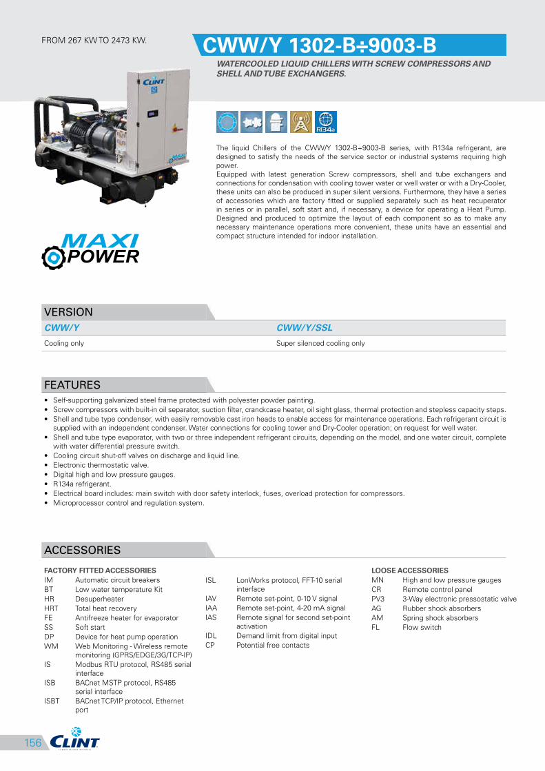
156
ISL LonWorks protocol, FFT-10 serial
interface
IAV Remote set-point, 0-10 V signal
IAA Remote set-point, 4-20 mA signal
IAS Remote signal for second set-point
activation
IDL Demand limit from digital input
CP Potential free contacts
FROM 267 KW TO 2473 KW.CWW/Y 1302-B÷9003-B
WATERCOOLED LIQUID CHILLERS WITH SCREW COMPRESSORS AND
SHELL AND TUBE EXCHANGERS.
The liquid Chillers of the CWW/Y 1302-B÷9003-B series, with R134a refrigerant, are
designed to satisfy the needs of the service sector or industrial systems requiring high
power.
Equipped with latest generation Screw compressors, shell and tube exchangers and
connections for condensation with cooling tower water or well water or with a Dry-Cooler,
these units can also be produced in super silent versions. Furthermore, they have a series
of accessories which are factory fitted or supplied separately such as heat recuperator
in series or in parallel, soft start and, if necessary, a device for operating a Heat Pump.
Designed and produced to optimize the layout of each component so as to make any
necessary maintenance operations more convenient, these units have an essential and
compact structure intended for indoor installation.
VERSION
CWW/Y CWW/Y/SSL
Cooling only Super silenced cooling only
FEATURES
• Self-supporting galvanized steel frame protected with polyester powder painting.
• Screw compressors with built-in oil separator, suction filter, cranckcase heater, oil sight glass, thermal protection and stepless capacity steps.
• Shell and tube type condenser, with easily removable cast iron heads to enable access for maintenance operations. Each refrigerant circuit is
supplied with an independent condenser. Water connections for cooling tower and Dry-Cooler operation; on request for well water.
• Shell and tube type evaporator, with two or three independent refrigerant circuits, depending on the model, and one water circuit, complete
with water differential pressure switch.
• Cooling circuit shut-off valves on discharge and liquid line.
• Electronic thermostatic valve.
• Digital high and low pressure gauges.
• R134a refrigerant.
• Electrical board includes: main switch with door safety interlock, fuses, overload protection for compressors.
• Microprocessor control and regulation system.
ACCESSORIES
FACTORY FITTED ACCESSORIES
IM Automatic circuit breakers
BT Low water temperature Kit
HR Desuperheater
HRT Total heat recovery
FE Antifreeze heater for evaporator
SS Soft start
DP Device for heat pump operation
WM Web Monitoring - Wireless remote
monitoring (GPRS/EDGE/3G/TCP-IP)
IS Modbus RTU protocol, RS485 serial
interface
ISB BACnet MSTP protocol, RS485
serial interface
ISBT BACnet TCP/IP protocol, Ethernet
port
LOOSE ACCESSORIES
MN High and low pressure gauges
CR Remote control panel
PV3 3-Way electronic pressostatic valve
AG Rubber shock absorbers
AM Spring shock absorbers
FL Flow switch
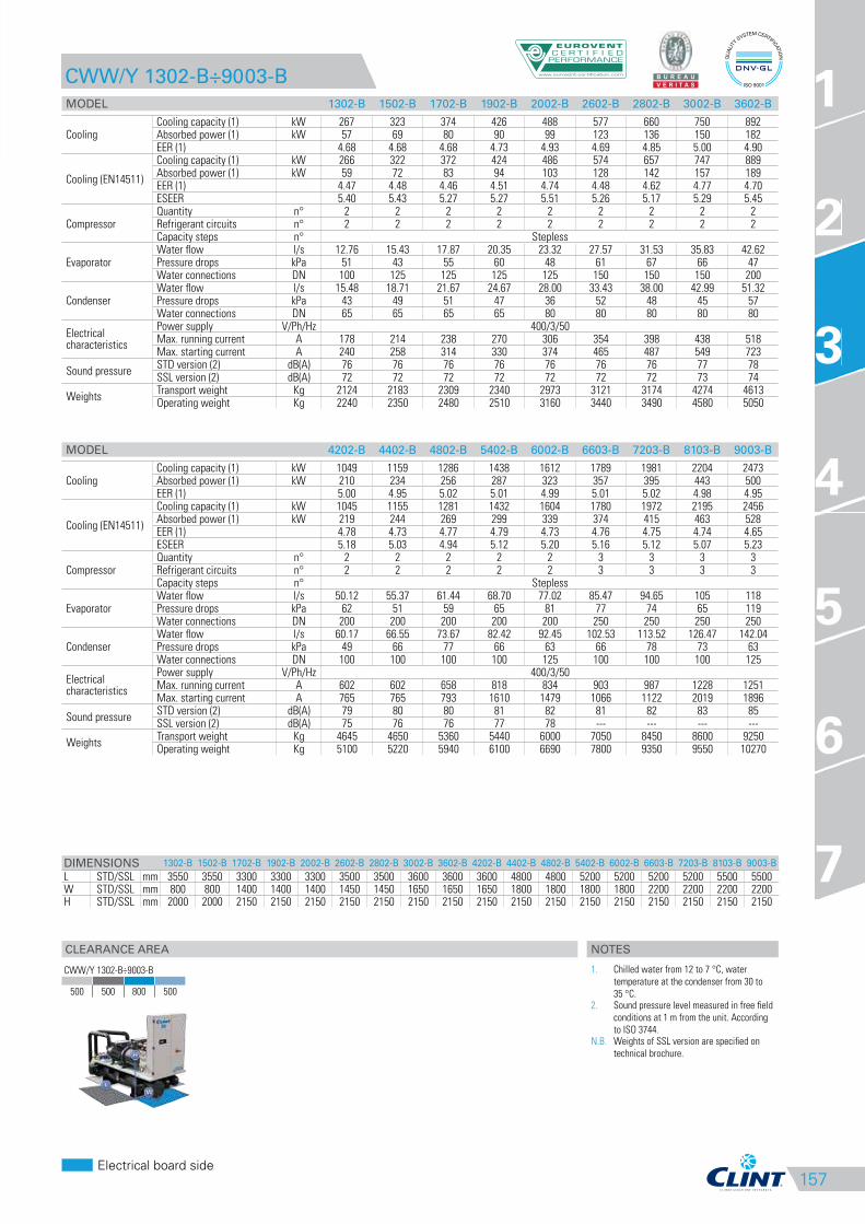
157
CLEARANCE AREA
Electrical board side
1
2
3
4
5
6
7
CWW/Y 1302-B÷9003-B
MODEL 1302-B 1502-B 1702-B 1902-B 2002-B 2602-B 2802-B 3002-B 3602-B
CoolingCooling capacity (1) kW 267 323 374 426 488 577 660 750 892Absorbed power (1) kW 57 69 80 90 99 123 136 150 182EER (1) 4.68 4.68 4.68 4.73 4.93 4.69 4.85 5.00 4.90
Cooling (EN14511)
Cooling capacity (1) kW 266 322 372 424 486 574 657 747 889Absorbed power (1) kW 59 72 83 94 103 128 142 157 189EER (1) 4.47 4.48 4.46 4.51 4.74 4.48 4.62 4.77 4.70ESEER 5.40 5.43 5.27 5.27 5.51 5.26 5.17 5.29 5.45
CompressorQuantity n° 2 2 2 2 2 2 2 2 2Refrigerant circuits n° 2 2 2 2 2 2 2 2 2Capacity steps n° Stepless
EvaporatorWater flow l/s 12.76 15.43 17.87 20.35 23.32 27.57 31.53 35.83 42.62Pressure drops kPa 51 43 55 60 48 61 67 66 47Water connections DN 100 125 125 125 125 150 150 150 200
CondenserWater flow l/s 15.48 18.71 21.67 24.67 28.00 33.43 38.00 42.99 51.32Pressure drops kPa 43 49 51 47 36 52 48 45 57Water connections DN 65 65 65 65 80 80 80 80 80
Electrical characteristics
Power supply V/Ph/Hz 400/3/50Max. running current A 178 214 238 270 306 354 398 438 518Max. starting current A 240 258 314 330 374 465 487 549 723
Sound pressureSTD version (2) dB(A) 76 76 76 76 76 76 76 77 78SSL version (2) dB(A) 72 72 72 72 72 72 72 73 74
WeightsTransport weight Kg 2124 2183 2309 2340 2973 3121 3174 4274 4613Operating weight Kg 2240 2350 2480 2510 3160 3440 3490 4580 5050
MODEL 4202-B 4402-B 4802-B 5402-B 6002-B 6603-B 7203-B 8103-B 9003-B
CoolingCooling capacity (1) kW 1049 1159 1286 1438 1612 1789 1981 2204 2473Absorbed power (1) kW 210 234 256 287 323 357 395 443 500EER (1) 5.00 4.95 5.02 5.01 4.99 5.01 5.02 4.98 4.95
Cooling (EN14511)
Cooling capacity (1) kW 1045 1155 1281 1432 1604 1780 1972 2195 2456Absorbed power (1) kW 219 244 269 299 339 374 415 463 528EER (1) 4.78 4.73 4.77 4.79 4.73 4.76 4.75 4.74 4.65ESEER 5.18 5.03 4.94 5.12 5.20 5.16 5.12 5.07 5.23
CompressorQuantity n° 2 2 2 2 2 3 3 3 3Refrigerant circuits n° 2 2 2 2 2 3 3 3 3Capacity steps n° Stepless
EvaporatorWater flow l/s 50.12 55.37 61.44 68.70 77.02 85.47 94.65 105 118Pressure drops kPa 62 51 59 65 81 77 74 65 119Water connections DN 200 200 200 200 200 250 250 250 250
CondenserWater flow l/s 60.17 66.55 73.67 82.42 92.45 102.53 113.52 126.47 142.04Pressure drops kPa 49 66 77 66 63 66 78 73 63Water connections DN 100 100 100 100 125 100 100 100 125
Electrical characteristics
Power supply V/Ph/Hz 400/3/50Max. running current A 602 602 658 818 834 903 987 1228 1251Max. starting current A 765 765 793 1610 1479 1066 1122 2019 1896
Sound pressureSTD version (2) dB(A) 79 80 80 81 82 81 82 83 85SSL version (2) dB(A) 75 76 76 77 78 --- --- --- ---
WeightsTransport weight Kg 4645 4650 5360 5440 6000 7050 8450 8600 9250Operating weight Kg 5100 5220 5940 6100 6690 7800 9350 9550 10270
DIMENSIONS 1302-B 1502-B 1702-B 1902-B 2002-B 2602-B 2802-B 3002-B 3602-B 4202-B 4402-B 4802-B 5402-B 6002-B 6603-B 7203-B 8103-B 9003-B
L STD/SSL mm 3550 3550 3300 3300 3300 3500 3500 3600 3600 3600 4800 4800 5200 5200 5200 5200 5500 5500W STD/SSL mm 800 800 1400 1400 1400 1450 1450 1650 1650 1650 1800 1800 1800 1800 2200 2200 2200 2200H STD/SSL mm 2000 2000 2150 2150 2150 2150 2150 2150 2150 2150 2150 2150 2150 2150 2150 2150 2150 2150
3
CWW/Y 1302-B÷9003-B
500 500 800 500
NOTES
1. Chilled water from 12 to 7 °C, water
temperature at the condenser from 30 to
35 °C.2. Sound pressure level measured in free field
conditions at 1 m from the unit. According
to ISO 3744.N.B. Weights of SSL version are specified on
technical brochure.
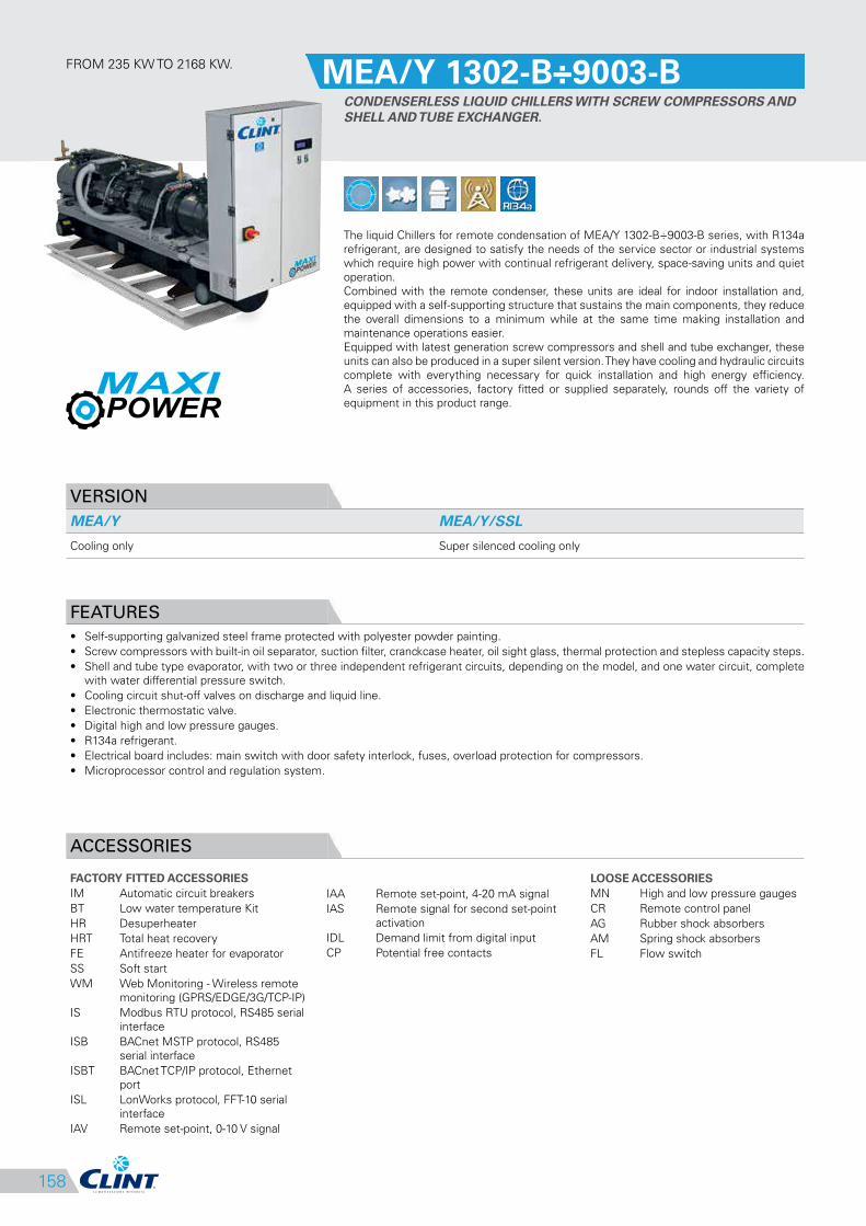
158
IAA Remote set-point, 4-20 mA signal
IAS Remote signal for second set-point
activation
IDL Demand limit from digital input
CP Potential free contacts
FROM 235 KW TO 2168 KW.MEA/Y 1302-B÷9003-B
CONDENSERLESS LIQUID CHILLERS WITH SCREW COMPRESSORS AND
SHELL AND TUBE EXCHANGER.
The liquid Chillers for remote condensation of MEA/Y 1302-B÷9003-B series, with R134a
refrigerant, are designed to satisfy the needs of the service sector or industrial systems
which require high power with continual refrigerant delivery, space-saving units and quiet
operation.
Combined with the remote condenser, these units are ideal for indoor installation and,
equipped with a self-supporting structure that sustains the main components, they reduce
the overall dimensions to a minimum while at the same time making installation and
maintenance operations easier.
Equipped with latest generation screw compressors and shell and tube exchanger, these
units can also be produced in a super silent version. They have cooling and hydraulic circuits
complete with everything necessary for quick installation and high energy efficiency.
A series of accessories, factory fitted or supplied separately, rounds off the variety of
equipment in this product range.
VERSION
MEA/Y MEA/Y/SSL
Cooling only Super silenced cooling only
FEATURES
• Self-supporting galvanized steel frame protected with polyester powder painting.
• Screw compressors with built-in oil separator, suction filter, cranckcase heater, oil sight glass, thermal protection and stepless capacity steps.
• Shell and tube type evaporator, with two or three independent refrigerant circuits, depending on the model, and one water circuit, complete
with water differential pressure switch.
• Cooling circuit shut-off valves on discharge and liquid line.
• Electronic thermostatic valve.
• Digital high and low pressure gauges.
• R134a refrigerant.
• Electrical board includes: main switch with door safety interlock, fuses, overload protection for compressors.
• Microprocessor control and regulation system.
ACCESSORIES
FACTORY FITTED ACCESSORIES
IM Automatic circuit breakers
BT Low water temperature Kit
HR Desuperheater
HRT Total heat recovery
FE Antifreeze heater for evaporator
SS Soft start
WM Web Monitoring - Wireless remote
monitoring (GPRS/EDGE/3G/TCP-IP)
IS Modbus RTU protocol, RS485 serial
interface
ISB BACnet MSTP protocol, RS485
serial interface
ISBT BACnet TCP/IP protocol, Ethernet
port
ISL LonWorks protocol, FFT-10 serial
interface
IAV Remote set-point, 0-10 V signal
LOOSE ACCESSORIES
MN High and low pressure gauges
CR Remote control panel
AG Rubber shock absorbers
AM Spring shock absorbers
FL Flow switch
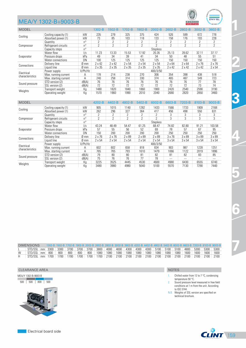
159
CLEARANCE AREA
Electrical board side
1
2
3
4
5
6
7
MEA/Y 1302-B÷9003-B
MODEL 1302-B 1502-B 1702-B 1902-B 2002-B 2602-B 2802-B 3002-B 3602-B
CoolingCooling capacity (1) kW 235 279 325 375 424 526 599 672 778Absorbed power (1) kW 73 85 103 118 133 158 176 193 228
CompressorQuantity n° 2 2 2 2 2 2 2 2 2Refrigerant circuits n° 2 2 2 2 2 2 2 2 2Capacity steps n° Stepless
EvaporatorWater flow l/s 11.23 13.33 15.53 17.92 20.26 25.13 28.62 32.11 37.17Pressure drops kPa 49 34 39 41 34 50 48 55 51Water connections DN 100 125 125 125 125 150 150 150 150
ConnectionsDelivery line Ø mm 2 x 42 2 x 42 2 x 54 2 x 54 2 x 54 2 x 64 2 x 64 2 x 76 2 x 76Liquid line Ø mm 2 x 35 2 x 35 2 x 35 2 x 35 2 x 35 2 x 42 2 x 42 2 x 42 2 x 54
Electrical characteristics
Power supply V/Ph/Hz 400/3/50Max. running current A 178 214 238 270 306 354 398 438 518Max. starting current A 240 258 314 330 374 465 487 549 723
Sound pressureSTD version (2) dB(A) 76 76 76 76 76 76 76 77 78SSL version (2) dB(A) 72 72 72 72 72 72 72 73 74
WeightsTransport weight Kg 1480 1820 1840 1860 1900 2420 2540 2590 3190Operating weight Kg 1570 1960 1990 2010 2040 2680 2820 2850 3460
MODEL 4202-B 4402-B 4802-B 5402-B 6002-B 6603-B 7203-B 8103-B 9003-B
CoolingCooling capacity (1) kW 905 1015 1140 1282 1433 1566 1733 1909 2168Absorbed power (1) kW 262 296 327 364 417 456 498 550 631
CompressorQuantity n° 2 2 2 2 2 3 3 3 3Refrigerant circuits n° 2 2 2 2 2 3 3 3 3Capacity steps n° Stepless
EvaporatorWater flow l/s 43.24 48.49 54.47 61.25 68.47 74.82 82.80 91.21 103.58Pressure drops kPa 57 55 56 52 69 78 57 67 95Water connections DN 150 200 200 200 200 250 250 250 250
ConnectionsDelivery line Ø mm 2 x 76 2 x 76 2 x 89 2 x 89 2 x 89 3 x 76 3 x 89 3 x 89 3 x 89Liquid line Ø mm 2 x 54 2 x 54 2 x 54 2 x 54 2 x 54 3 x 54 3 x 54 3 x 54 3 x 54
Electrical characteristics
Power supply V/Ph/Hz 400/3/50Max. running current A 602 602 658 818 834 903 987 1228 1251Max. starting current A 765 765 793 1610 1479 1066 1122 2019 1896
Sound pressureSTD version (2) dB(A) 79 80 80 81 82 81 82 83 85SSL version (2) dB(A) 75 76 76 77 78 --- --- --- ---
WeightsTransport weight Kg 3225 3525 4445 4530 4600 4980 6430 6555 6740Operating weight Kg 3480 3980 4980 5040 5100 5570 7130 7290 7440
DIMENSIONS 1302-B 1502-B 1702-B 1902-B 2002-B 2602-B 2802-B 3002-B 3602-B 4202-B 4402-B 4802-B 5402-B 6002-B 6603-B 7203-B 8103-B 9003-B
L STD/SSL mm 3300 3300 3700 3700 3700 3800 4000 4000 4300 4300 4300 5100 5100 5100 4800 5300 5300 5300W STD/SSL mm 800 800 800 800 800 1080 1080 1080 1080 1080 1080 1080 1080 1080 1600 1600 1600 1600H STD/SSL mm 1700 1700 1700 1700 1700 1700 2100 2100 2100 2100 2100 2100 2100 2100 2100 2100 2100 2100
3
MEA/Y 1302-B÷9003-B
500 500 800 500
NOTES
1. Chilled water from 12 to 7 °C, condensing
temperature 50 °C.2. Sound pressure level measured in free field
conditions at 1 m from the unit. According
to ISO 3744.N.B. Weights of SSL version are specified on
technical brochure.
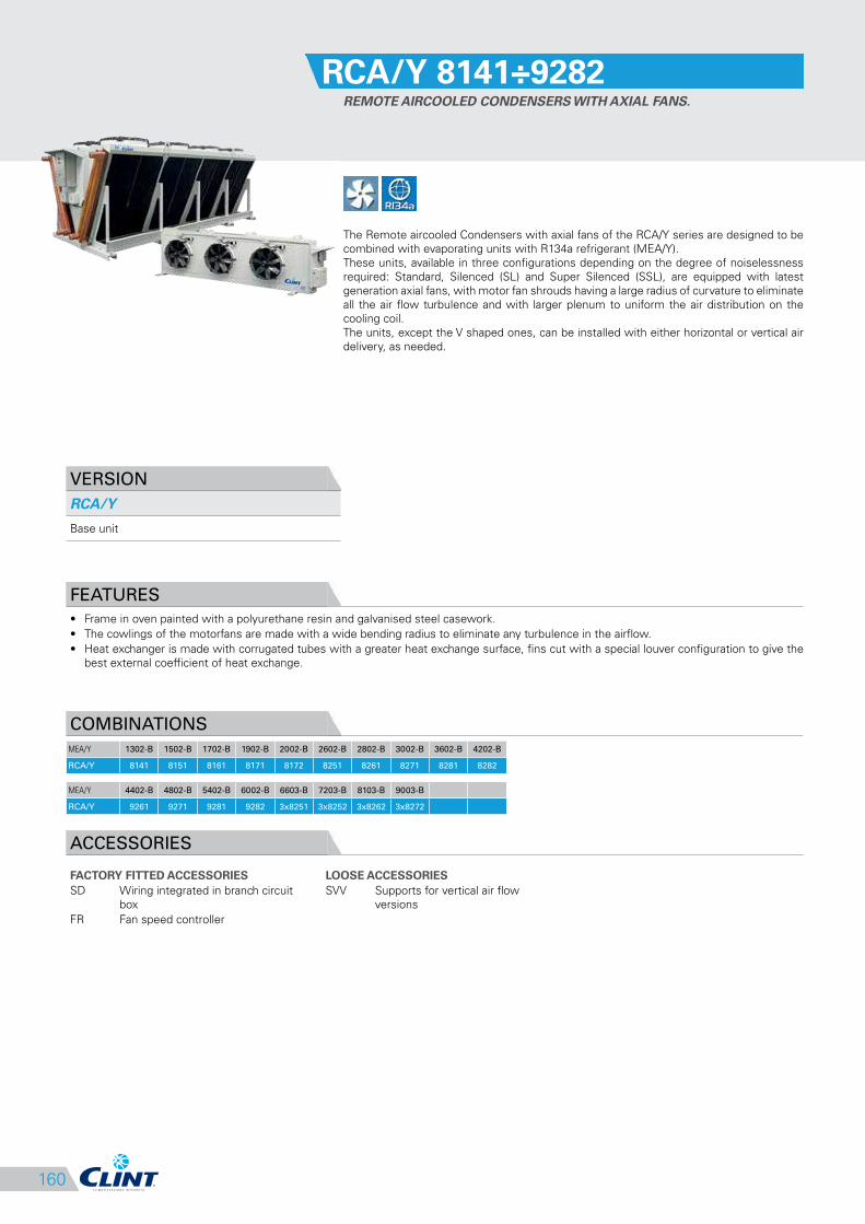
160
RCA/Y 8141÷9282
REMOTE AIRCOOLED CONDENSERS WITH AXIAL FANS.
The Remote aircooled Condensers with axial fans of the RCA/Y series are designed to be
combined with evaporating units with R134a refrigerant (MEA/Y).
These units, available in three configurations depending on the degree of noiselessness
required: Standard, Silenced (SL) and Super Silenced (SSL), are equipped with latest
generation axial fans, with motor fan shrouds having a large radius of curvature to eliminate
all the air flow turbulence and with larger plenum to uniform the air distribution on the
cooling coil.
The units, except the V shaped ones, can be installed with either horizontal or vertical air
delivery, as needed.
VERSION
RCA/Y
Base unit
FEATURES
• Frame in oven painted with a polyurethane resin and galvanised steel casework.
• The cowlings of the motorfans are made with a wide bending radius to eliminate any turbulence in the airflow.
• Heat exchanger is made with corrugated tubes with a greater heat exchange surface, fins cut with a special louver configuration to give the
best external coefficient of heat exchange.
COMBINATIONS
MEA/Y 1302-B 1502-B 1702-B 1902-B 2002-B 2602-B 2802-B 3002-B 3602-B 4202-B
RCA/Y 8141 8151 8161 8171 8172 8251 8261 8271 8281 8282
MEA/Y 4402-B 4802-B 5402-B 6002-B 6603-B 7203-B 8103-B 9003-B
RCA/Y 9261 9271 9281 9282 3x8251 3x8252 3x8262 3x8272
ACCESSORIES
FACTORY FITTED ACCESSORIES
SD Wiring integrated in branch circuit
box
FR Fan speed controller
LOOSE ACCESSORIES
SVV Supports for vertical air flow
versions

161
CLEARANCE AREA
Electrical board side
1
2
3
4
5
6
7
RCA/Y 8141÷9282
MODEL 8141 8151 8161 8171 8172 8251 8252 8261 8262
Fan Quantity n° 4 5 6 7 7 10 10 12 12
ConnectionsIn Ø mm 2X64 2X64 2X76 2X76 2X76 2X64 2X64 2X76 2X76Out Ø mm 2x42 2x42 2x42 2x54 2x54 2x42 2x42 2x42 2x42
Electrical characteristics
Power supply V/Ph/Hz 400/3/50Absorbed power kW 7.40 9.25 11.10 12.95 12.95 9.25 9.25 11.10 11.10Absorbed current A 11.40 14.25 17.10 19.95 19.95 14.25 14.25 17.10 17.10
Sound pressure STD version (1) dB(A) 55 56 57 57 57 58 58 59 59
WeightsTransport weight Kg 637 794 950 1027 1107 1325 1222 1461 1585Operating weight Kg 669 833 1022 1091 1192 1395 1276 1561 1716
MODEL 8271 8272 8281 8282 9261 9271 9281 9282
Fan Quantity n° 14 14 16 16 12 14 16 16
ConnectionsIn Ø mm 2X76 2X76 2X76 2X76 2X76 2X76 2X76 2X76Out Ø mm 2x54 2x54 2x54 2x54 2X64 2X64 2X64 2X64
Electrical characteristics
Power supply V/Ph/Hz 400/3/50Absorbed power kW 12.95 12.95 14.80 14.80 12.60 14.70 16.80 16.80Absorbed current A 19.95 19.95 22.80 22.80 19.20 22.40 25.60 25.60
Sound pressure STD version (1) dB(A) 59 59 60 60 57 57 58 58
WeightsTransport weight Kg 1702 1845 1942 2106 3056 3515 3974 3974Operating weight Kg 1855 1998 2074 2280 3187 3666 4145 4145
DIMENSIONS 8141 8151 8161 8171 8172 8251 8252 8261 8262 8271 8272 8281 8282 9261 9271 9281 9282
L STD mm 5930 7280 8630 9980 9980 7280 7280 8630 8630 9980 9980 11330 11330 7990 9240 10490 10490W STD mm 1380 1380 1380 1380 1380 2400 2400 2400 2400 2400 2400 2400 2400 2400 2400 2400 2400H STD mm 1565 1565 1565 1565 1565 1565 1565 1565 1565 1565 1565 1565 1565 2260 2260 2260 2260
3
RCA/Y 8141÷8282
RCA/Y 9261÷9282
NOTES
1. Sound pressure level measured in free field
conditions at 10 m from the unit. According
to ISO 3744.N.B. Combinations are made at condensing
temperature 50 °C, ambient air temperature
35 °C.N.B. Clearance areas are specified on
installation, use and maintenance manual.

162
RCA/Y/SL 8231÷9282
SILENCED REMOTE AIRCOOLED CONDENSERS WITH AXIAL FANS.
The Remote aircooled Condensers with axial fans of the RCA/Y/SL series are designed to
be combined with evaporating units with R134a refrigerant (MEA/Y).
These units, available in three configurations depending on the degree of noiselessness
required: Standard, Silenced (SL) and Super Silenced (SSL), are equipped with latest
generation axial fans, with motor fan shrouds having a large radius of curvature to eliminate
all the air flow turbulence and with larger plenum to uniform the air distribution on the
cooling coil.
The units, except the V shaped ones, can be installed with either horizontal or vertical air
delivery, as needed.
VERSION
RCA/Y/SL
Silenced unit
FEATURES
• Frame in oven painted with a polyurethane resin and galvanised steel casework.
• The cowlings of the motorfans are made with a wide bending radius to eliminate any turbulence in the airflow.
• Heat exchanger is made with corrugated tubes with a greater heat exchange surface, fins cut with a special louver configuration to give the
best external coefficient of heat exchange.
COMBINATIONS
MEA/Y 1302-B 1502-B 1702-B 1902-B 2002-B 2602-B 2802-B 3002-B 3602-B 4202-B
RCA/Y/SL 8231 8232 8241 8242 8251 8261 8271 8281 9261 9271
MEA/Y 4402-B 4802-B 5402-B 6002-B 6603-B 7203-B 8103-B 9003-B
RCA/Y/SL 9281 9282 2x8272 2x8282 3x9171 3x9172 3x9251 3x9252
ACCESSORIES
FACTORY FITTED ACCESSORIES
SD Wiring integrated in branch circuit
box
FR Fan speed controller
LOOSE ACCESSORIES
SVV Supports for vertical air flow
versions
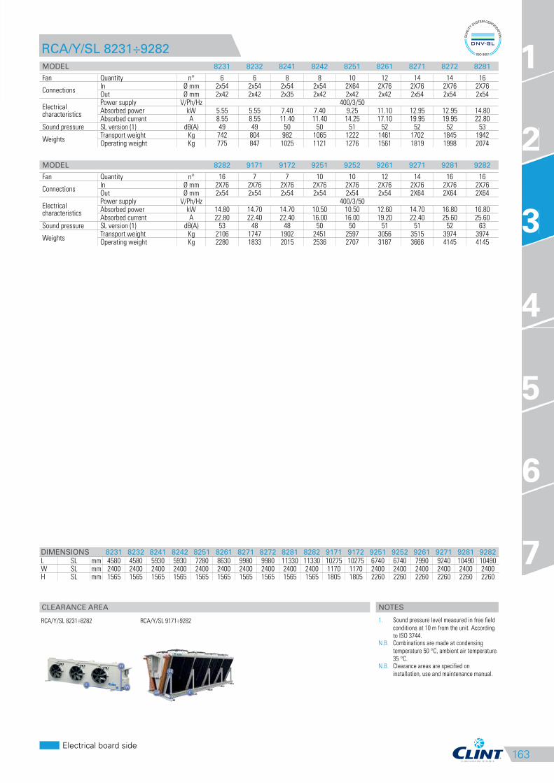
163
CLEARANCE AREA
Electrical board side
1
2
3
4
5
6
7
RCA/Y/SL 8231÷9282
MODEL 8231 8232 8241 8242 8251 8261 8271 8272 8281
Fan Quantity n° 6 6 8 8 10 12 14 14 16
ConnectionsIn Ø mm 2x54 2x54 2x54 2x54 2X64 2X76 2X76 2X76 2X76Out Ø mm 2x42 2x42 2x35 2x42 2x42 2x42 2x54 2x54 2x54
Electrical characteristics
Power supply V/Ph/Hz 400/3/50Absorbed power kW 5.55 5.55 7.40 7.40 9.25 11.10 12.95 12.95 14.80Absorbed current A 8.55 8.55 11.40 11.40 14.25 17.10 19.95 19.95 22.80
Sound pressure SL version (1) dB(A) 49 49 50 50 51 52 52 52 53
WeightsTransport weight Kg 742 804 982 1065 1222 1461 1702 1845 1942Operating weight Kg 775 847 1025 1121 1276 1561 1819 1998 2074
MODEL 8282 9171 9172 9251 9252 9261 9271 9281 9282
Fan Quantity n° 16 7 7 10 10 12 14 16 16
ConnectionsIn Ø mm 2X76 2X76 2X76 2X76 2X76 2X76 2X76 2X76 2X76Out Ø mm 2x54 2x54 2x54 2x54 2x54 2x54 2X64 2X64 2X64
Electrical characteristics
Power supply V/Ph/Hz 400/3/50Absorbed power kW 14.80 14.70 14.70 10.50 10.50 12.60 14.70 16.80 16.80Absorbed current A 22.80 22.40 22.40 16.00 16.00 19.20 22.40 25.60 25.60
Sound pressure SL version (1) dB(A) 53 48 48 50 50 51 51 52 63
WeightsTransport weight Kg 2106 1747 1902 2451 2597 3056 3515 3974 3974Operating weight Kg 2280 1833 2015 2536 2707 3187 3666 4145 4145
DIMENSIONS 8231 8232 8241 8242 8251 8261 8271 8272 8281 8282 9171 9172 9251 9252 9261 9271 9281 9282
L SL mm 4580 4580 5930 5930 7280 8630 9980 9980 11330 11330 10275 10275 6740 6740 7990 9240 10490 10490W SL mm 2400 2400 2400 2400 2400 2400 2400 2400 2400 2400 1170 1170 2400 2400 2400 2400 2400 2400H SL mm 1565 1565 1565 1565 1565 1565 1565 1565 1565 1565 1805 1805 2260 2260 2260 2260 2260 2260
3
RCA/Y/SL 8231÷8282
RCA/Y/SL 9171÷9282
NOTES
1. Sound pressure level measured in free field
conditions at 10 m from the unit. According
to ISO 3744.N.B. Combinations are made at condensing
temperature 50 °C, ambient air temperature
35 °C.N.B. Clearance areas are specified on
installation, use and maintenance manual.
164
RCA/Y/SSL 8151÷9281
SUPER SILENCED REMOTE AIRCOOLED CONDENSERS WITH AXIAL
FANS.
The Remote aircooled Condensers with axial fans of the RCA/Y/SSL series are designed to
be combined with evaporating units with R134a refrigerant (MEA/Y).
These units, available in three configurations depending on the degree of noiselessness
required: Standard, Silenced (SL) and Super Silenced (SSL), are equipped with latest
generation axial fans, with motor fan shrouds having a large radius of curvature to eliminate
all the air flow turbulence and with larger plenum to uniform the air distribution on the
cooling coil.
The units, except the V shaped ones, can be installed with either horizontal or vertical air
delivery, as needed.
VERSION
RCA/Y/SSL
Super silenced unit
FEATURES
• Frame in oven painted with a polyurethane resin and galvanised steel casework.
• The cowlings of the motorfans are made with a wide bending radius to eliminate any turbulence in the airflow.
• Heat exchanger is made with corrugated tubes with a greater heat exchange surface, fins cut with a special louver configuration to give the
best external coefficient of heat exchange.
COMBINATIONS
MEA/Y 1302-B 1502-B 1702-B 1902-B 2002-B 2602-B 2802-B 3002-B 3602-B 4202-B
RCA/Y/SSL 8151 8161 8171 8251 8251 8261 8272 8282 9271 9272
MEA/Y 4402-B 4802-B 5402-B 6002-B 6603-B 7203-B 8103-B 9003-B
RCA/Y/SSL 9281 2x8271 2x8281 2x8282 3x8261 3x8271 3x8272 3x8281
ACCESSORIES
FACTORY FITTED ACCESSORIES
SD Wiring integrated in branch circuit
box
FR Fan speed controller
LOOSE ACCESSORIES
SVV Supports for vertical air flow
versions
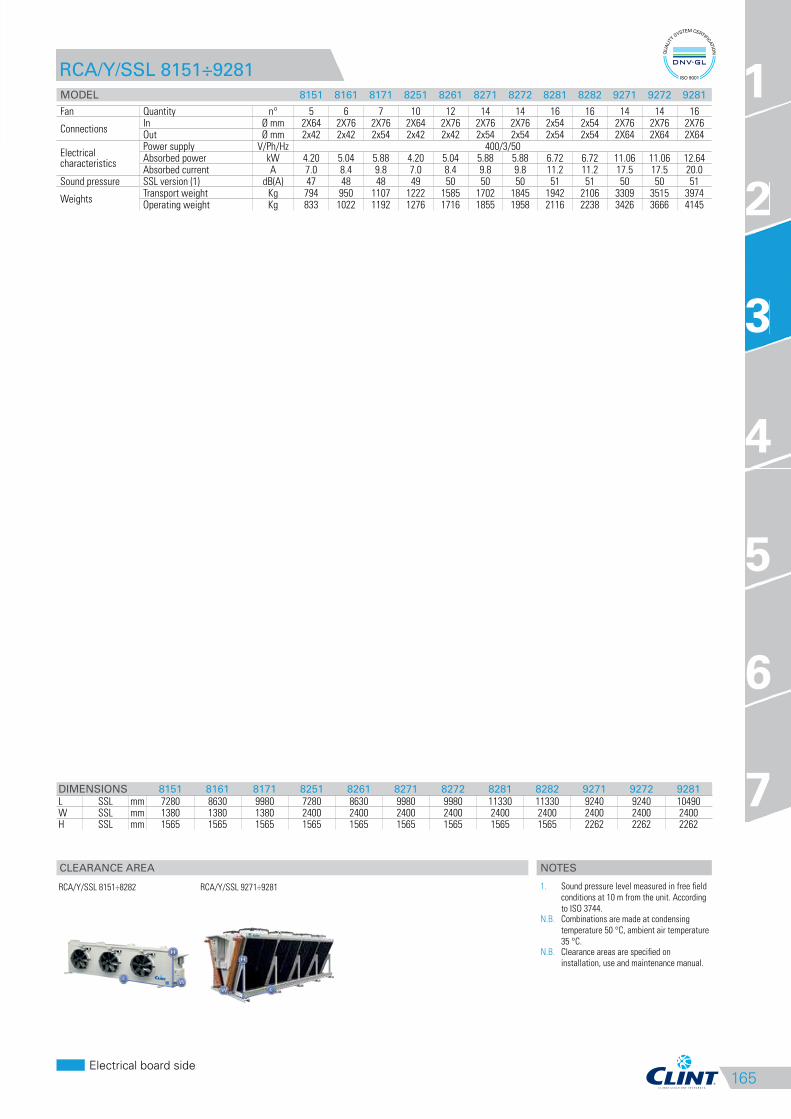
165
CLEARANCE AREA
Electrical board side
1
2
3
4
5
6
7
RCA/Y/SSL 8151÷9281
MODEL 8151 8161 8171 8251 8261 8271 8272 8281 8282 9271 9272 9281
Fan Quantity n° 5 6 7 10 12 14 14 16 16 14 14 16
ConnectionsIn Ø mm 2X64 2X76 2X76 2X64 2X76 2X76 2X76 2x54 2x54 2X76 2X76 2X76Out Ø mm 2x42 2x42 2x54 2x42 2x42 2x54 2x54 2x54 2x54 2X64 2X64 2X64
Electrical characteristics
Power supply V/Ph/Hz 400/3/50Absorbed power kW 4.20 5.04 5.88 4.20 5.04 5.88 5.88 6.72 6.72 11.06 11.06 12.64Absorbed current A 7.0 8.4 9.8 7.0 8.4 9.8 9.8 11.2 11.2 17.5 17.5 20.0
Sound pressure SSL version (1) dB(A) 47 48 48 49 50 50 50 51 51 50 50 51
WeightsTransport weight Kg 794 950 1107 1222 1585 1702 1845 1942 2106 3309 3515 3974Operating weight Kg 833 1022 1192 1276 1716 1855 1958 2116 2238 3426 3666 4145
DIMENSIONS 8151 8161 8171 8251 8261 8271 8272 8281 8282 9271 9272 9281
L SSL mm 7280 8630 9980 7280 8630 9980 9980 11330 11330 9240 9240 10490W SSL mm 1380 1380 1380 2400 2400 2400 2400 2400 2400 2400 2400 2400H SSL mm 1565 1565 1565 1565 1565 1565 1565 1565 1565 2262 2262 2262
3
RCA/Y/SSL 8151÷8282
RCA/Y/SSL 9271÷9281
NOTES
1. Sound pressure level measured in free field
conditions at 10 m from the unit. According
to ISO 3744.N.B. Combinations are made at condensing
temperature 50 °C, ambient air temperature
35 °C.N.B. Clearance areas are specified on
installation, use and maintenance manual.
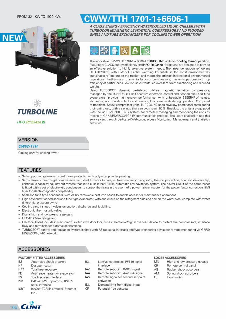
166
ISL LonWorks protocol, FFT-10 serial
interface
IAV Remote set-point, 0-10 V signal
IAA Remote set-point, 4-20 mA signal
IAS Remote signal for second set-point
activation
IDL Demand limit from digital input
CP Potential free contacts
FROM 321 KW TO 1922 KW.CWW/TTH 1701-1÷6606-1
A CLASS ENERGY EFFICIENCY WATERCOOLED LIQUID CHILLERS WITH
TURBOCOR (MAGNETIC LEVITATION) COMPRESSORS AND FLOODED
SHELL AND TUBE EXCHANGERS FOR COOLING TOWER OPERATION.
The innovative CWW/TTH 1701-1 ÷ 6606-1 TURBOLINE units for cooling tower operation,
featuring A CLASS energy efficiency and HFO-R1234ze refrigerant, are designed to provide
an effective solution to highly selective system needs. The latest generation refrigerant
HFO-R1234ze, with GWP<1 (Global warming Potential), is the most environmentally
sustainable refrigerant on the market, and meets the strictest international environmental
regulations. Furthermore, thanks to Turbocor compressors, the units perform with top
efficiency at partial loads, low inrush currents, an excellent silent functioning and reduced
weight.
Using TURBOCOR dynamic partial-load oil-free magnetic levitation compressors,
managed by the TURBOSOFT self-adaptive electronic control and flooded shell and tube
evaporators, provide high energy performance, with unbeatable ESEER/IPLV values,
eliminating accumulation tanks and reaching low noise levels during operation. Compared
to traditional Screw compressor units, TURBOLINE units have low operational costs during
their entire use, with a savings that can even reach 50%. Besides, the units are equipped
with the WEB MONITORING system, for remotely managing and monitoring the units by
means of GPRS/EDGE/3G/TCP-IP communication protocol. The users enabled to use this
service can, through dedicated Web page, access Monitoring, Management and Statistics
activities.
VERSION
CWW/TTH
Cooling only for cooling tower
FEATURES
• Self-supporting galvanized steel frame protected with polyester powder painting.
• Semi-hermetic centrifugal compressors with dual Turbocor turbine, oil free, magnetic rising rotor, thermal protection, flow and delivery tap,
continuous capacity adjustment system thanks to built-in INVERTER, automatic anti-cavitation system. The power circuit of the compressor
is fitted with a set of electrolytic condensers to control the rising in the event of a power failure, reactor for the power factor correction, EMI
filter for electromagnetic compatibility.
• Shell and tube type condenser, with easily removable cast iron heads to enable access for maintenance operations.
• High efficiency flooded shell and tube type evaporator, with one circuit on the refrigerant side and one on the water side, complete with water
differential pressure switch.
• Cooling circuit shut-off valves on suction, discharge and liquid line.
• Electronic thermostatic valve.
• Digital high and low pressure gauges.
• HFO-R1234ze refrigerant.
• Electrical board includes: main on-off switch with door lock, fuses, electronic/digital overload device to protect the compressors, interface
relay and terminals for external connections.
• TURBOSOFT control and regulation system is fitted with RS485 serial interface and Web Monitoring device for remote monitoring via GPRS/
EDGE/3G/TCP-IP network.
ACCESSORIES
FACTORY FITTED ACCESSORIES
IM Automatic circuit breakers
HR Desuperheater
HRT Total heat recovery
FE Antifreeze heater for evaporator
TS Touch screen interface
ISB BACnet MSTP protocol, RS485
serial interface
ISBT BACnet TCP/IP protocol, Ethernet
port
LOOSE ACCESSORIES
MN High and low pressure gauges
CR Remote control panel
AG Rubber shock absorbers
AM Spring shock absorbers
FL Flow switch
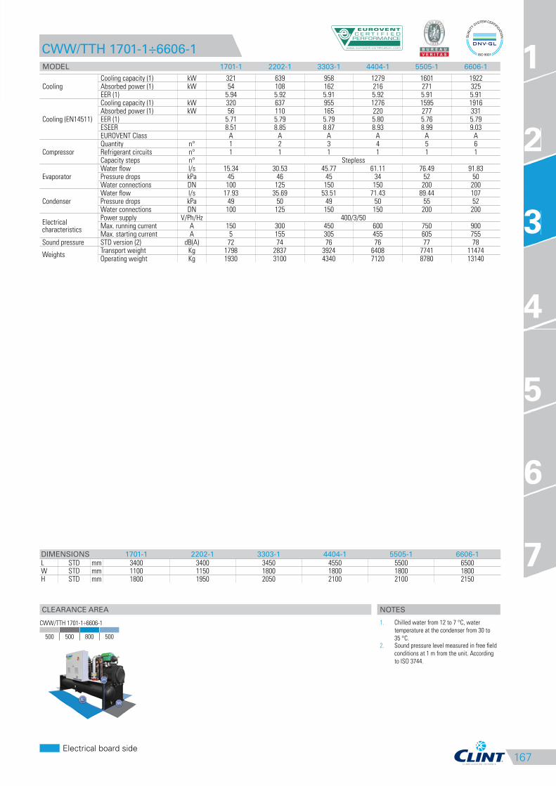
167
CLEARANCE AREA
Electrical board side
1
2
3
4
5
6
7
CWW/TTH 1701-1÷6606-1
MODEL 1701-1 2202-1 3303-1 4404-1 5505-1 6606-1
CoolingCooling capacity (1) kW 321 639 958 1279 1601 1922Absorbed power (1) kW 54 108 162 216 271 325EER (1) 5.94 5.92 5.91 5.92 5.91 5.91
Cooling (EN14511)
Cooling capacity (1) kW 320 637 955 1276 1595 1916Absorbed power (1) kW 56 110 165 220 277 331EER (1) 5.71 5.79 5.79 5.80 5.76 5.79ESEER 8.51 8.85 8.87 8.93 8.99 9.03EUROVENT Class A A A A A A
CompressorQuantity n° 1 2 3 4 5 6Refrigerant circuits n° 1 1 1 1 1 1Capacity steps n° Stepless
EvaporatorWater flow l/s 15.34 30.53 45.77 61.11 76.49 91.83Pressure drops kPa 45 46 45 34 52 50Water connections DN 100 125 150 150 200 200
CondenserWater flow l/s 17.93 35.69 53.51 71.43 89.44 107Pressure drops kPa 49 50 49 50 55 52Water connections DN 100 125 150 150 200 200
Electrical characteristics
Power supply V/Ph/Hz 400/3/50Max. running current A 150 300 450 600 750 900Max. starting current A 5 155 305 455 605 755
Sound pressure STD version (2) dB(A) 72 74 76 76 77 78
WeightsTransport weight Kg 1798 2837 3924 6408 7741 11474Operating weight Kg 1930 3100 4340 7120 8780 13140
DIMENSIONS 1701-1 2202-1 3303-1 4404-1 5505-1 6606-1
L STD mm 3400 3400 3450 4550 5500 6500W STD mm 1100 1150 1800 1800 1800 1800H STD mm 1800 1950 2050 2100 2100 2150
3
CWW/TTH 1701-1÷6606-1
500 500 800 500
NOTES
1. Chilled water from 12 to 7 °C, water
temperature at the condenser from 30 to
35 °C.2. Sound pressure level measured in free field
conditions at 1 m from the unit. According
to ISO 3744.
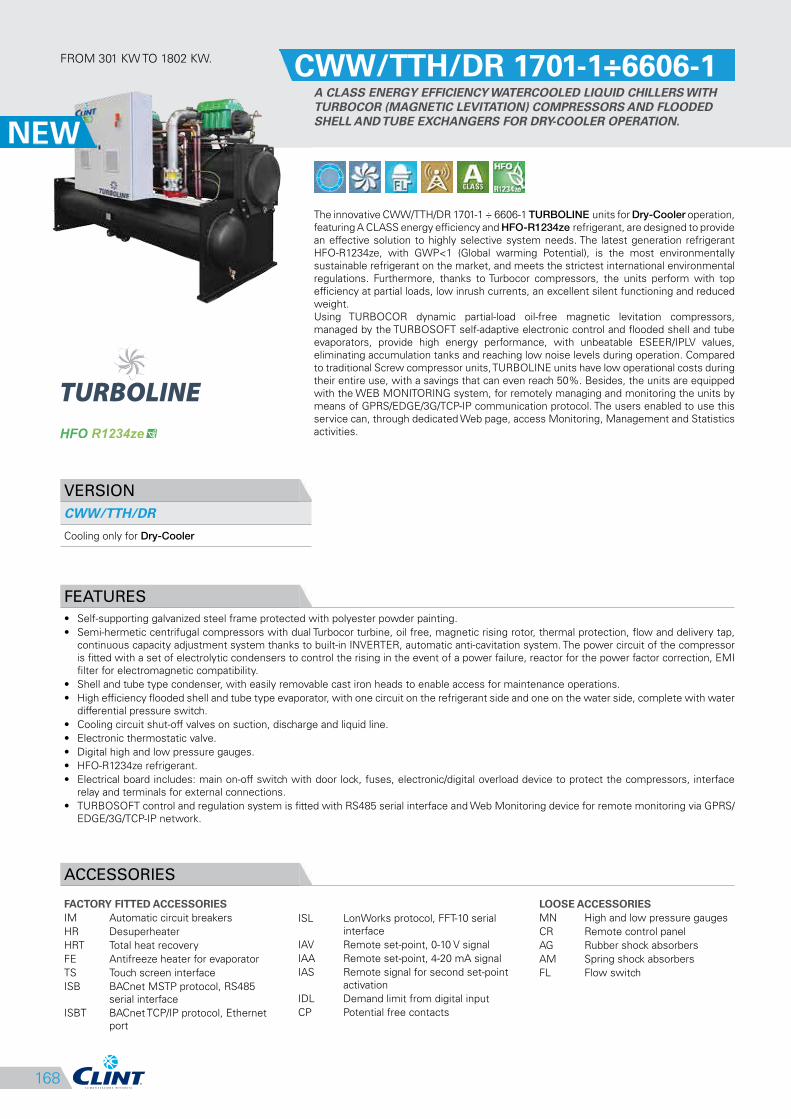
168
ISL LonWorks protocol, FFT-10 serial
interface
IAV Remote set-point, 0-10 V signal
IAA Remote set-point, 4-20 mA signal
IAS Remote signal for second set-point
activation
IDL Demand limit from digital input
CP Potential free contacts
FROM 301 KW TO 1802 KW.CWW/TTH/DR 1701-1÷6606-1
A CLASS ENERGY EFFICIENCY WATERCOOLED LIQUID CHILLERS WITH
TURBOCOR (MAGNETIC LEVITATION) COMPRESSORS AND FLOODED
SHELL AND TUBE EXCHANGERS FOR DRY-COOLER OPERATION.
The innovative CWW/TTH/DR 1701-1 ÷ 6606-1 TURBOLINE units for Dry-Cooler operation,
featuring A CLASS energy efficiency and HFO-R1234ze refrigerant, are designed to provide
an effective solution to highly selective system needs. The latest generation refrigerant
HFO-R1234ze, with GWP<1 (Global warming Potential), is the most environmentally
sustainable refrigerant on the market, and meets the strictest international environmental
regulations. Furthermore, thanks to Turbocor compressors, the units perform with top
efficiency at partial loads, low inrush currents, an excellent silent functioning and reduced
weight.
Using TURBOCOR dynamic partial-load oil-free magnetic levitation compressors,
managed by the TURBOSOFT self-adaptive electronic control and flooded shell and tube
evaporators, provide high energy performance, with unbeatable ESEER/IPLV values,
eliminating accumulation tanks and reaching low noise levels during operation. Compared
to traditional Screw compressor units, TURBOLINE units have low operational costs during
their entire use, with a savings that can even reach 50%. Besides, the units are equipped
with the WEB MONITORING system, for remotely managing and monitoring the units by
means of GPRS/EDGE/3G/TCP-IP communication protocol. The users enabled to use this
service can, through dedicated Web page, access Monitoring, Management and Statistics
activities.
VERSION
CWW/TTH/DR
Cooling only for Dry-Cooler
FEATURES
• Self-supporting galvanized steel frame protected with polyester powder painting.
• Semi-hermetic centrifugal compressors with dual Turbocor turbine, oil free, magnetic rising rotor, thermal protection, flow and delivery tap,
continuous capacity adjustment system thanks to built-in INVERTER, automatic anti-cavitation system. The power circuit of the compressor
is fitted with a set of electrolytic condensers to control the rising in the event of a power failure, reactor for the power factor correction, EMI
filter for electromagnetic compatibility.
• Shell and tube type condenser, with easily removable cast iron heads to enable access for maintenance operations.
• High efficiency flooded shell and tube type evaporator, with one circuit on the refrigerant side and one on the water side, complete with water
differential pressure switch.
• Cooling circuit shut-off valves on suction, discharge and liquid line.
• Electronic thermostatic valve.
• Digital high and low pressure gauges.
• HFO-R1234ze refrigerant.
• Electrical board includes: main on-off switch with door lock, fuses, electronic/digital overload device to protect the compressors, interface
relay and terminals for external connections.
• TURBOSOFT control and regulation system is fitted with RS485 serial interface and Web Monitoring device for remote monitoring via GPRS/
EDGE/3G/TCP-IP network.
ACCESSORIES
FACTORY FITTED ACCESSORIES
IM Automatic circuit breakers
HR Desuperheater
HRT Total heat recovery
FE Antifreeze heater for evaporator
TS Touch screen interface
ISB BACnet MSTP protocol, RS485
serial interface
ISBT BACnet TCP/IP protocol, Ethernet
port
LOOSE ACCESSORIES
MN High and low pressure gauges
CR Remote control panel
AG Rubber shock absorbers
AM Spring shock absorbers
FL Flow switch

169
CLEARANCE AREA
Electrical board side
1
2
3
4
5
6
7
CWW/TTH/DR 1701-1÷6606-1
MODEL 1701-1 2202-1 3303-1 4404-1 5505-1 6606-1
CoolingCooling capacity (1) kW 301 603 899 1203 1499 1802Absorbed power (1) kW 71 142 212 283 354 424EER (1) 4.24 4.25 4.24 4.25 4.23 4.25
Cooling (EN14511)Cooling capacity (1) kW 300 601 896 1200 1494 1797Absorbed power (1) kW 72 144 215 286 359 429EER (1) 4.17 4.17 4.17 4.20 4.16 4.19
CompressorQuantity n° 1 2 3 4 5 6Refrigerant circuits n° 1 1 1 1 1 1Capacity steps n° Stepless
EvaporatorWater flow l/s 14.38 28.81 42.95 57.48 71.62 86.10Pressure drops kPa 41 42 41 30 47 44Water connections DN 100 125 150 150 200 200
CondenserWater flow l/s 19,40 38,80 58,00 77,70 96,70 116Pressure drops kPa 55 56 55 56 62 58Water connections DN 100 125 150 150 200 200
Electrical characteristics
Power supply V/Ph/Hz 400/3/50Max. running current A 150 300 450 600 750 900Max. starting current A 5 155 305 455 605 755
Sound pressure STD version (2) dB(A) 72 74 76 76 77 78
WeightsTransport weight Kg 1849 2919 4065 6587 7942 11716Operating weight Kg 1990 3200 4510 7340 9040 13460
DIMENSIONS 1701-1 2202-1 3303-1 4404-1 5505-1 6606-1
L STD mm 3400 3400 3450 4550 5500 6500W STD mm 1100 1150 1800 1800 1800 1800H STD mm 1800 1950 2050 2100 2100 2150
3
CWW/TTH/DR 1701-1÷6606-1
500 500 800 500
NOTES
1. Chilled water from 12 to 7 °C, temperature
at the condenser (with ethylene glycol at
35%) from 40 to 45 °C.2. Sound pressure level measured in free field
conditions at 1 m from the unit. According
to ISO 3744.

170
ISL LonWorks protocol, FFT-10 serial
interface
IAV Remote set-point, 0-10 V signal
IAA Remote set-point, 4-20 mA signal
IAS Remote signal for second set-point
activation
IDL Demand limit from digital input
CP Potential free contacts
FROM 319 KW TO 3912 KW.CWW/TTY 1601-1÷14406-1
A CLASS ENERGY EFFICIENCY WATERCOOLED LIQUID CHILLERS WITH
TURBOCOR (MAGNETIC LEVITATION) COMPRESSORS AND FLOODED
SHELL AND TUBE EXCHANGERS FOR COOLING TOWER OPERATION.
The innovative CWW/TTY 1601-1 ÷ 14406-1 TURBOLINE units for cooling tower operation,
featuring A CLASS energy efficiency, are designed to provide an effective solution to highly
selective system needs. Efficiency at partial loads, low breakaway starting current, low
levels of operational noise, reduced weight and the specific design and handling every
manufacturing aspect, make the TURBOLINE series the top of the range.
Using TURBOCOR dynamic partial-load oil-free magnetic levitation compressors,
managed by the TURBOSOFT self-adaptive electronic control and flooded shell and tube
evaporators, provide high energy performance, with unbeatable ESEER/IPLV values,
eliminating accumulation tanks and reaching low noise levels during operation. Compared
to traditional Screw compressor units, TURBOLINE units have low operational costs during
their entire use, with a savings that can even reach 50%. Besides, the units are equipped
with the WEB MONITORING system, for remotely managing and monitoring the units by
means of GPRS/EDGE/3G/TCP-IP communication protocol. The users enabled to use this
service can, through dedicated Web page, access Monitoring, Management and Statistics
activities.
VERSION
CWW/TTY
Cooling only for cooling tower
FEATURES
• Self-supporting galvanized steel frame protected with polyester powder painting.
• Semi-hermetic centrifugal compressors with dual Turbocor turbine, oil free, magnetic rising rotor, thermal protection, flow and delivery tap,
continuous capacity adjustment system thanks to built-in INVERTER, automatic anti-cavitation system. The power circuit of the compressor
is fitted with a set of electrolytic condensers to control the rising in the event of a power failure, reactor for the power factor correction, EMI
filter for electromagnetic compatibility.
• Shell and tube type condenser, with easily removable cast iron heads to enable access for maintenance operations.
• High efficiency flooded shell and tube type evaporator, with one circuit on the refrigerant side and one on the water side, complete with water
differential pressure switch.
• Cooling circuit shut-off valves on suction, discharge and liquid line.
• Electronic thermostatic valve.
• Digital high and low pressure gauges.
• R134a refrigerant.
• Electrical board includes: main on-off switch with door lock, fuses, electronic/digital overload device to protect the compressors, interface
relay and terminals for external connections.
• TURBOSOFT control and regulation system is fitted with RS485 serial interface and Web Monitoring device for remote monitoring via GPRS/
EDGE/3G/TCP-IP network.
ACCESSORIES
FACTORY FITTED ACCESSORIES
IM Automatic circuit breakers
HR Desuperheater
HRT Total heat recovery
FE Antifreeze heater for evaporator
TS Touch screen interface
ISB BACnet MSTP protocol, RS485
serial interface
ISBT BACnet TCP/IP protocol, Ethernet
port
LOOSE ACCESSORIES
MN High and low pressure gauges
CR Remote control panel
AG Rubber shock absorbers
AM Spring shock absorbers
FL Flow switch
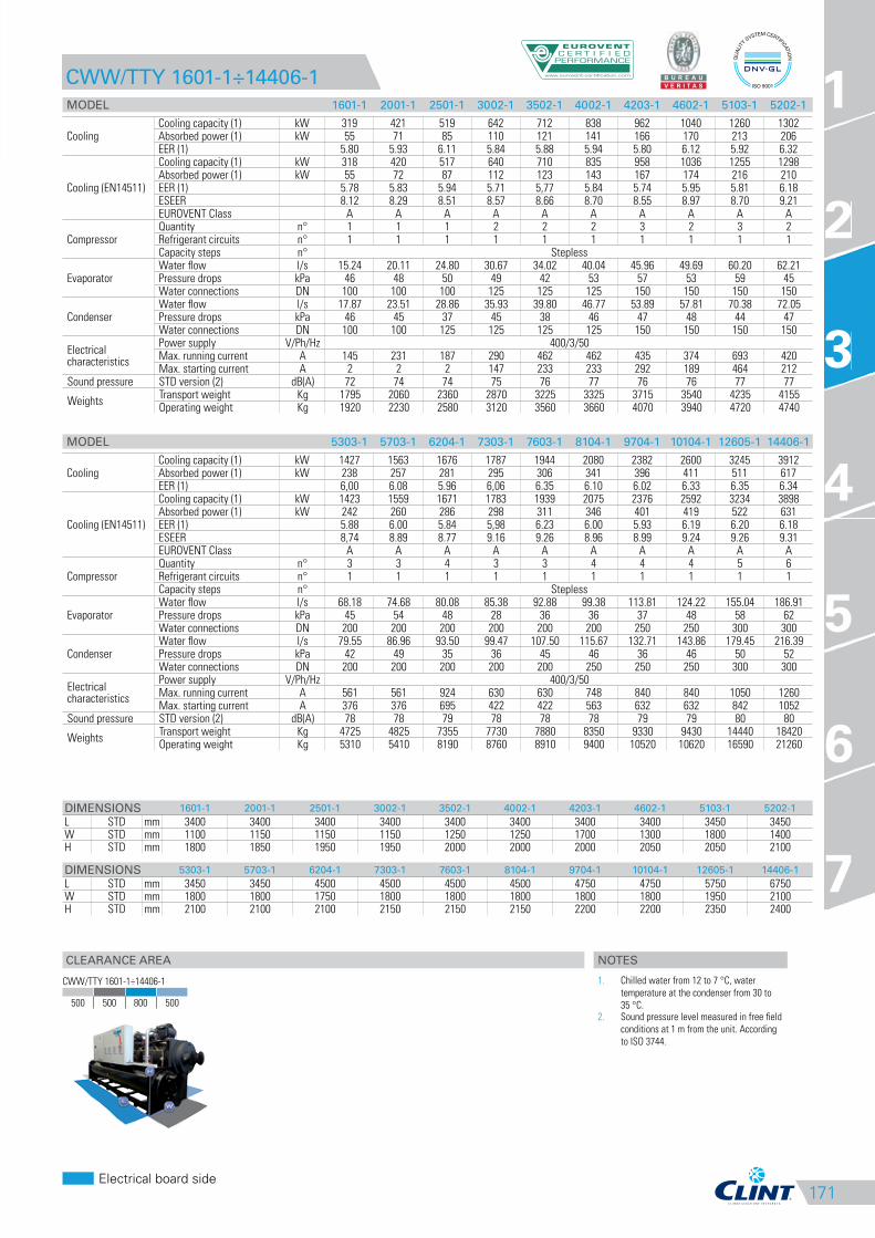
171
CLEARANCE AREA
Electrical board side
1
2
3
4
5
6
7
CWW/TTY 1601-1÷14406-1
3
CWW/TTY 1601-1÷14406-1
500 500 800 500
NOTES
1. Chilled water from 12 to 7 °C, water
temperature at the condenser from 30 to
35 °C.2. Sound pressure level measured in free field
conditions at 1 m from the unit. According
to ISO 3744.
MODEL 5303-1 5703-1 6204-1 7303-1 7603-1 8104-1 9704-1 10104-1 12605-1 14406-1
CoolingCooling capacity (1) kW 1427 1563 1676 1787 1944 2080 2382 2600 3245 3912Absorbed power (1) kW 238 257 281 295 306 341 396 411 511 617EER (1) 6,00 6.08 5.96 6,06 6.35 6.10 6.02 6.33 6.35 6.34
Cooling (EN14511)
Cooling capacity (1) kW 1423 1559 1671 1783 1939 2075 2376 2592 3234 3898Absorbed power (1) kW 242 260 286 298 311 346 401 419 522 631EER (1) 5.88 6.00 5.84 5,98 6.23 6.00 5.93 6.19 6.20 6.18ESEER 8,74 8.89 8.77 9.16 9.26 8.96 8.99 9.24 9.26 9.31EUROVENT Class A A A A A A A A A A
CompressorQuantity n° 3 3 4 3 3 4 4 4 5 6Refrigerant circuits n° 1 1 1 1 1 1 1 1 1 1Capacity steps n° Stepless
EvaporatorWater flow l/s 68.18 74.68 80.08 85.38 92.88 99.38 113.81 124.22 155.04 186.91Pressure drops kPa 45 54 48 28 36 36 37 48 58 62Water connections DN 200 200 200 200 200 200 250 250 300 300
CondenserWater flow l/s 79.55 86.96 93.50 99.47 107.50 115.67 132.71 143.86 179.45 216.39Pressure drops kPa 42 49 35 36 45 46 36 46 50 52Water connections DN 200 200 200 200 200 250 250 250 300 300
Electrical characteristics
Power supply V/Ph/Hz 400/3/50Max. running current A 561 561 924 630 630 748 840 840 1050 1260Max. starting current A 376 376 695 422 422 563 632 632 842 1052
Sound pressure STD version (2) dB(A) 78 78 79 78 78 78 79 79 80 80
WeightsTransport weight Kg 4725 4825 7355 7730 7880 8350 9330 9430 14440 18420Operating weight Kg 5310 5410 8190 8760 8910 9400 10520 10620 16590 21260
DIMENSIONS 1601-1 2001-1 2501-1 3002-1 3502-1 4002-1 4203-1 4602-1 5103-1 5202-1
L STD mm 3400 3400 3400 3400 3400 3400 3400 3400 3450 3450W STD mm 1100 1150 1150 1150 1250 1250 1700 1300 1800 1400H STD mm 1800 1850 1950 1950 2000 2000 2000 2050 2050 2100
DIMENSIONS 5303-1 5703-1 6204-1 7303-1 7603-1 8104-1 9704-1 10104-1 12605-1 14406-1
L STD mm 3450 3450 4500 4500 4500 4500 4750 4750 5750 6750W STD mm 1800 1800 1750 1800 1800 1800 1800 1800 1950 2100H STD mm 2100 2100 2100 2150 2150 2150 2200 2200 2350 2400
MODEL 1601-1 2001-1 2501-1 3002-1 3502-1 4002-1 4203-1 4602-1 5103-1 5202-1
CoolingCooling capacity (1) kW 319 421 519 642 712 838 962 1040 1260 1302Absorbed power (1) kW 55 71 85 110 121 141 166 170 213 206EER (1) 5.80 5.93 6.11 5.84 5.88 5.94 5.80 6.12 5.92 6.32
Cooling (EN14511)
Cooling capacity (1) kW 318 420 517 640 710 835 958 1036 1255 1298Absorbed power (1) kW 55 72 87 112 123 143 167 174 216 210EER (1) 5.78 5.83 5.94 5.71 5,77 5.84 5.74 5.95 5.81 6.18ESEER 8.12 8.29 8.51 8.57 8.66 8.70 8.55 8.97 8.70 9.21EUROVENT Class A A A A A A A A A A
CompressorQuantity n° 1 1 1 2 2 2 3 2 3 2Refrigerant circuits n° 1 1 1 1 1 1 1 1 1 1Capacity steps n° Stepless
EvaporatorWater flow l/s 15.24 20.11 24.80 30.67 34.02 40.04 45.96 49.69 60.20 62.21Pressure drops kPa 46 48 50 49 42 53 57 53 59 45Water connections DN 100 100 100 125 125 125 150 150 150 150
CondenserWater flow l/s 17.87 23.51 28.86 35.93 39.80 46.77 53.89 57.81 70.38 72.05Pressure drops kPa 46 45 37 45 38 46 47 48 44 47Water connections DN 100 100 125 125 125 125 150 150 150 150
Electrical characteristics
Power supply V/Ph/Hz 400/3/50Max. running current A 145 231 187 290 462 462 435 374 693 420Max. starting current A 2 2 2 147 233 233 292 189 464 212
Sound pressure STD version (2) dB(A) 72 74 74 75 76 77 76 76 77 77
WeightsTransport weight Kg 1795 2060 2360 2870 3225 3325 3715 3540 4235 4155Operating weight Kg 1920 2230 2580 3120 3560 3660 4070 3940 4720 4740
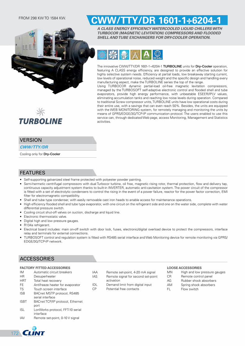
172
IAA Remote set-point, 4-20 mA signal
IAS Remote signal for second set-point
activation
IDL Demand limit from digital input
CP Potential free contacts
FROM 298 KW TO 1584 KW.CWW/TTY/DR 1601-1÷6204-1
A CLASS ENERGY EFFICIENCY WATERCOOLED LIQUID CHILLERS WITH
TURBOCOR (MAGNETIC LEVITATION) COMPRESSORS AND FLOODED
SHELL AND TUBE EXCHANGERS FOR DRY-COOLER OPERATION.
The innovative CWW/TTY/DR 1601-1÷6204-1 TURBOLINE units for Dry-Cooler operation,
featuring A CLASS energy efficiency, are designed to provide an effective solution for
highly selective system needs. Efficiency at partial loads, low breakaway starting current,
low levels of operational noise, reduced weight and the specific design and handling every
manufacturing aspect, make the TURBOLINE series the top of the range.
Using TURBOCOR dynamic partial-load oil-free magnetic levitation compressors,
managed by the TURBOSOFT self-adaptive electronic control and flooded shell and tube
evaporators, provide high energy performance, with unbeatable ESEER/IPLV values,
eliminating accumulation tanks and reaching low noise levels during operation. Compared
to traditional Screw compressor units, TURBOLINE units have low operational costs during
their entire use, with a savings that can even reach 50%. Besides, the units are equipped
with the WEB MONITORING system, for remotely managing and monitoring the units by
means of GPRS/EDGE/3G/TCP-IP communication protocol. The users enabled to use this
service can, through dedicated Web page, access Monitoring, Management and Statistics
activities.
VERSION
CWW/TTY/DR
Cooling only for Dry-Cooler
FEATURES
• Self-supporting galvanized steel frame protected with polyester powder painting.
• Semi-hermetic centrifugal compressors with dual Turbocor turbine, oil free, magnetic rising rotor, thermal protection, flow and delivery tap,
continuous capacity adjustment system thanks to built-in INVERTER, automatic anti-cavitation system. The power circuit of the compressor
is fitted with a set of electrolytic condensers to control the rising in the event of a power failure, reactor for the power factor correction, EMI
filter for electromagnetic compatibility.
• Shell and tube type condenser, with easily removable cast iron heads to enable access for maintenance operations.
• High efficiency flooded shell and tube type evaporator, with one circuit on the refrigerant side and one on the water side, complete with water
differential pressure switch.
• Cooling circuit shut-off valves on suction, discharge and liquid line.
• Electronic thermostatic valve.
• Digital high and low pressure gauges.
• R134a refrigerant.
• Electrical board includes: main on-off switch with door lock, fuses, electronic/digital overload device to protect the compressors, interface
relay and terminals for external connections.
• TURBOSOFT control and regulation system is fitted with RS485 serial interface and Web Monitoring device for remote monitoring via GPRS/
EDGE/3G/TCP-IP network.
ACCESSORIES
FACTORY FITTED ACCESSORIES
IM Automatic circuit breakers
HR Desuperheater
HRT Total heat recovery
FE Antifreeze heater for evaporator
TS Touch screen interface
ISB BACnet MSTP protocol, RS485
serial interface
ISBT BACnet TCP/IP protocol, Ethernet
port
ISL LonWorks protocol, FFT-10 serial
interface
IAV Remote set-point, 0-10 V signal
LOOSE ACCESSORIES
MN High and low pressure gauges
CR Remote control panel
AG Rubber shock absorbers
AM Spring shock absorbers
FL Flow switch
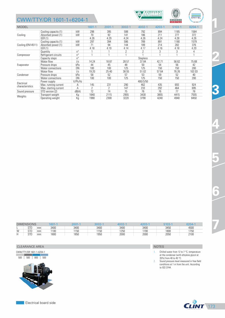
173
CLEARANCE AREA
Electrical board side
1
2
3
4
5
6
7
CWW/TTY/DR 1601-1÷6204-1
MODEL 1601-1 2001-1 3002-1 4002-1 4203-1 5103-1 6204-1
CoolingCooling capacity (1) kW 298 395 598 792 894 1185 1584Absorbed power (1) kW 70 92 141 186 211 277 372EER (1) 4.26 4.29 4.24 4.26 4.24 4.28 4.26
Cooling (EN14511)Cooling capacity (1) kW 297 394 596 789 891 1180 1579Absorbed power (1) kW 71 94 144 189 214 282 376EER (1) 4.18 4.19 4.14 4.17 4.16 4.18 4.20
CompressorQuantity n° 1 1 2 2 3 3 4Refrigerant circuits n° 1 1 1 1 1 1 1Capacity steps n° Stepless
EvaporatorWater flow l/s 14.24 18.87 28.57 37.84 42.71 56.62 75.68Pressure drops kPa 44 45 48 50 54 56 42Water connections DN 100 100 125 125 150 150 200
CondenserWater flow l/s 19.20 25.40 38.55 51.02 57.64 76.26 102.03Pressure drops kPa 58 52 57 53 59 52 40Water connections DN 100 100 125 125 150 150 200
Electrical characteristics
Power supply V/Ph/Hz 400/3/50Max. running current A 145 231 290 462 435 693 924Max. starting current A 2 2 147 233 292 464 695
Sound pressure STD version (2) dB(A) 72 74 75 76 76 77 78
WeightsTransport weight Kg 1840 2115 2955 3430 3855 4415 7555Operating weight Kg 1980 2300 3220 3790 4240 4940 8450
DIMENSIONS 1601-1 2001-1 3002-1 4002-1 4203-1 5103-1 6204-1
L STD mm 3400 3400 3400 3400 3400 3450 4500W STD mm 1100 1150 1150 1250 1700 1800 1750H STD mm 1800 1850 1950 2000 2000 2050 2100
3
CWW/TTY/DR 1601-1÷6204-1
500 500 800 500
NOTES
1. Chilled water from 12 to 7 °C, temperature
at the condenser (with ethylene glycol at
35%) from 40 to 45 °C.2. Sound pressure level measured in free field
conditions at 1 m from the unit. According
to ISO 3744.
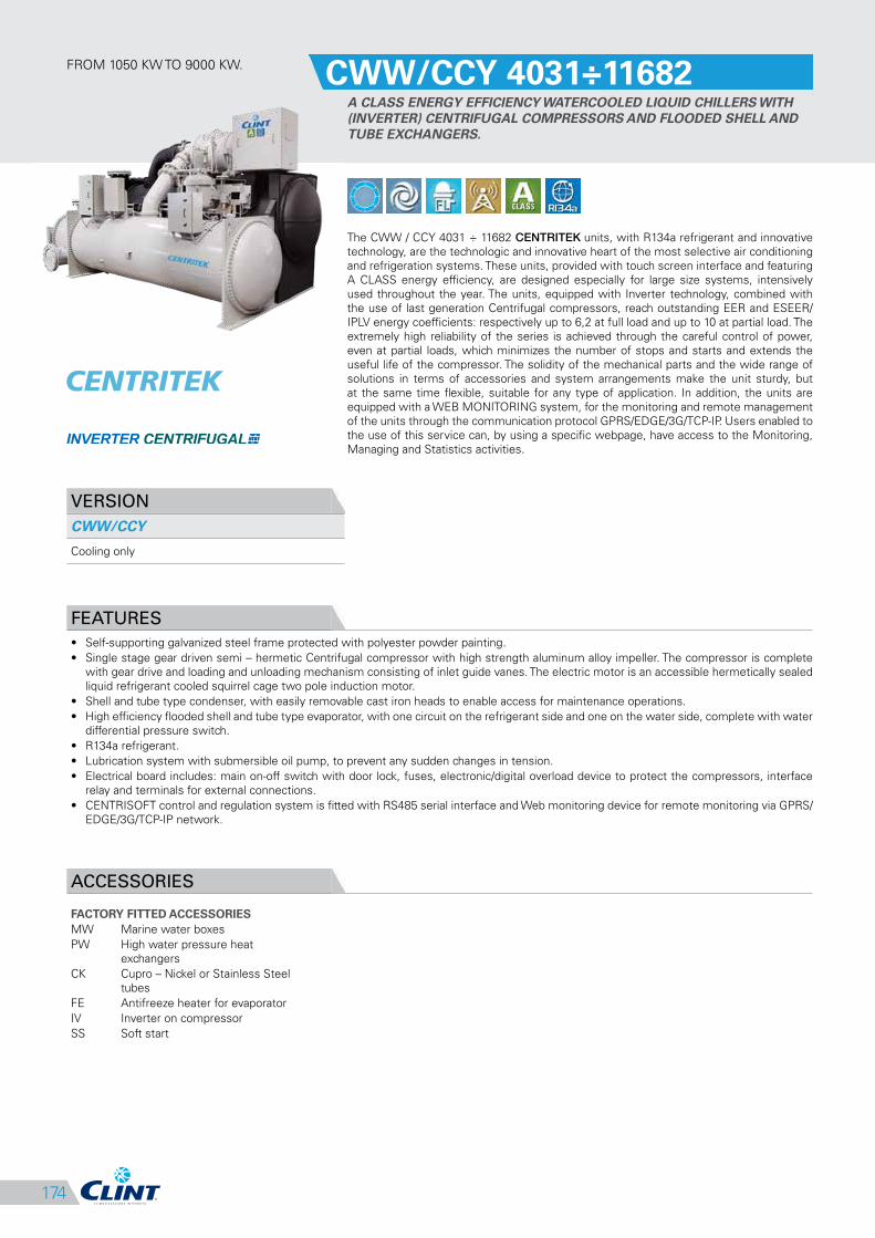
174
FROM 1050 KW TO 9000 KW.CWW/CCY 4031÷11682
A CLASS ENERGY EFFICIENCY WATERCOOLED LIQUID CHILLERS WITH
(INVERTER) CENTRIFUGAL COMPRESSORS AND FLOODED SHELL AND
TUBE EXCHANGERS.
The CWW / CCY 4031 ÷ 11682 CENTRITEK units, with R134a refrigerant and innovative
technology, are the technologic and innovative heart of the most selective air conditioning
and refrigeration systems. These units, provided with touch screen interface and featuring
A CLASS energy efficiency, are designed especially for large size systems, intensively
used throughout the year. The units, equipped with Inverter technology, combined with
the use of last generation Centrifugal compressors, reach outstanding EER and ESEER/
IPLV energy coefficients: respectively up to 6,2 at full load and up to 10 at partial load. The
extremely high reliability of the series is achieved through the careful control of power,
even at partial loads, which minimizes the number of stops and starts and extends the
useful life of the compressor. The solidity of the mechanical parts and the wide range of
solutions in terms of accessories and system arrangements make the unit sturdy, but
at the same time flexible, suitable for any type of application. In addition, the units are
equipped with a WEB MONITORING system, for the monitoring and remote management
of the units through the communication protocol GPRS/EDGE/3G/TCP-IP. Users enabled to
the use of this service can, by using a specific webpage, have access to the Monitoring,
Managing and Statistics activities.
VERSION
CWW/CCY
Cooling only
FEATURES
• Self-supporting galvanized steel frame protected with polyester powder painting.
• Single stage gear driven semi – hermetic Centrifugal compressor with high strength aluminum alloy impeller. The compressor is complete
with gear drive and loading and unloading mechanism consisting of inlet guide vanes. The electric motor is an accessible hermetically sealed
liquid refrigerant cooled squirrel cage two pole induction motor.
• Shell and tube type condenser, with easily removable cast iron heads to enable access for maintenance operations.
• High efficiency flooded shell and tube type evaporator, with one circuit on the refrigerant side and one on the water side, complete with water
differential pressure switch.
• R134a refrigerant.
• Lubrication system with submersible oil pump, to prevent any sudden changes in tension.
• Electrical board includes: main on-off switch with door lock, fuses, electronic/digital overload device to protect the compressors, interface
relay and terminals for external connections.
• CENTRISOFT control and regulation system is fitted with RS485 serial interface and Web monitoring device for remote monitoring via GPRS/
EDGE/3G/TCP-IP network.
ACCESSORIES
FACTORY FITTED ACCESSORIES
MW Marine water boxes
PW High water pressure heat
exchangers
CK Cupro – Nickel or Stainless Steel
tubes
FE Antifreeze heater for evaporator
IV Inverter on compressor
SS Soft start
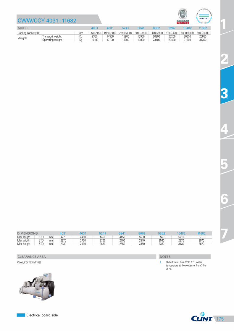
175
CLEARANCE AREA
Electrical board side
1
2
3
4
5
6
7
CWW/CCY 4031÷11682
MODEL 4031 4631 5241 5841 8062 9262 10482 11682
Cooling capacity (1) kW 1050÷2150 1950÷3000 2650÷3000 3000÷4400 1400÷2300 2100÷4300 4000÷6000 5600÷9000
WeightsTransport weight Kg 9350 14550 15900 15900 20200 20200 26850 26850Operating weight Kg 10100 17100 19000 19000 23400 23400 31300 31300
DIMENSIONS 4031 4631 5241 5841 8062 9262 10482 11682
Max length STD mm 4270 4450 4450 4450 5560 5560 5710 5710Max width STD mm 2670 2700 2700 2700 2540 2540 2970 2970Max height STD mm 2030 2490 2650 2650 2350 2350 3130 2870
3
CWW/CCY 4031÷11682
NOTES
1. Chilled water from 12 to 7 °C, water
temperature at the condenser from 30 to
35 °C.


![HVAC products and systems - Hidria product-overview[1].pdf• Air towers Air regulation units ... water air cooling coils, evaporating coils for cooling ... Condenserless water chillers](https://img.pdfslide.net/doc/110x75/5abd549a7f8b9ab02d8b7659/hvac-products-and-systems-product-overview1pdf-air-towers-air-regulation.jpg)