Embed Size (px)
Citation preview

Cisco ON78-20702-02
C H A P T E R 3
Install the Control CardsNote The terms “Unidirectional Path Switched Ring” and “UPSR” may appear in Cisco literature. These terms do not refer to using Cisco ONS 15xxx products in a unidirectional path switched ring configuration. Rather, these terms, as well as “Path Protected Mesh Network” and “PPMN”, refer generally to Cisco's path protection feature, which may be used in any topological network configuration. Cisco does not recommend using its path protection feature in any particular topological network configuration.
This chapter describes the common-control cards needed for the Cisco ONS 15454, Cisco ONS 15454 M2, and Cisco ONS 15454 M6 platforms and provides installation and card turn up procedures.
For card safety and compliance information, refer to the Regulatory Compliance and Safety Information for Cisco CPT and Cisco ONS Platforms document.
Note Unless otherwise specified, “ONS 15454” refers to both ANSI and ETSI shelf assemblies.
Note The cards described in this chapter are supported on the Cisco ONS 15454, Cisco ONS 15454 M6, Cisco ONS 15454 M2 platforms, unless noted otherwise.
Chapter topics include:
• 3.1 Card Overview, page 3-2
• 3.3 TCC2 Card, page 3-4
• “3.3.3 Related Procedures for TCC2 Card” section on page 3-6
• 3.4 TCC2P Card, page 3-6
• “3.4.3 Related Procedures for TCC2P Card” section on page 3-9
• 3.5 TCC3 Card, page 3-9
• 3.5.3 Related Procedures for TCC3 Card, page 3-12
• 3.6 TNC and TNCE Card, page 3-12
• 3.6.3 Related Procedures for TNC and TNCE Cards, page 3-16
• 3.7 TSC and TSCE Cards, page 3-16
• 3.7.3 Related Procedures for TSC and TSCE Cards, page 3-19
3-1S 15454 DWDM Configuration Guide, Release 9.6.x

Chapter 3 Install the Control Cards3.1 Card Overview
• 3.8 Digital Image Signing, page 3-20
• 3.8.2 Related Procedures for DIS, page 3-20
• 3.9 AIC-I Card, page 3-20
• 3.9.8 Related Procedures for AIC-I Card, page 3-26
• 3.10 MS-ISC-100T Card, page 3-26
• 3.10.3 Related Procedures for MS-ISC-100T Card, page 3-28
• 3.11 Front Mount Electrical Connections, page 3-29
• 3.12 Procedures for Control Cards, page 3-34
3.1 Card OverviewThe card overview section lists the cards described in this chapter.
Each card is marked with a symbol that corresponds to a slot (or slots) on the ONS 15454 shelf assembly. The cards are then installed into slots displaying the same symbols. For a list of slots and symbols, see the “Card Slot Requirements” section in the Cisco ONS 15454 Hardware Installation Guide.
3.1.1 Common Control CardsThe following common control cards are needed to support the functions of the DWDM, transponder, and muxponder cards on ONS 15454 shelf:
• TCC2 or TCC2P or TCC3
• AIC-I (optional)
• MS-ISC-100T (multishelf configurations only)
The TNC, TNCE, TSC, and TSCE cards are used to support the functions of DWDM, transponder, and muxponder cards on the Cisco ONS 15454 M2 and Cisco ONS 15454 M6 shelves.
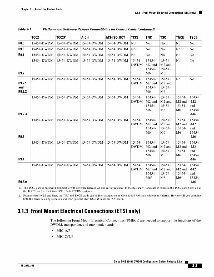
3.1.2 Card CompatibilityTable 3-1 lists the platform and software release compatibility for the control cards.
Table 3-1 Platform and Software Release Compatibility for Control Cards
TCC2 TCC2P AIC-I MS-ISC-100T TCC31 TNC TSC TNCE TSCE
R4.5 15454-DWDM 15454-DWDM 15454-DWDM 15454-DWDM No No No No No
R4.6 15454-DWDM 15454-DWDM 15454-DWDM 15454-DWDM No No No No No
R4.7 15454-DWDM 15454-DWDM 15454-DWDM 15454-DWDM No No No No No
R5.0 15454-DWDM 15454-DWDM 15454-DWDM 15454-DWDM No No No No No
R6.0 15454-DWDM 15454-DWDM 15454-DWDM 15454-DWDM No No No No No
R7.0 15454-DWDM 15454-DWDM 15454-DWDM 15454-DWDM No No No No No
R7.2 15454-DWDM 15454-DWDM 15454-DWDM 15454-DWDM No No No No No
R8.0 15454-DWDM 15454-DWDM 15454-DWDM 15454-DWDM No No No No No
3-2Cisco ONS 15454 DWDM Configuration Guide, Release 9.6.x
78-20702-02
Chapter 3 Install the Control Cards3.1.3 Front Mount Electrical Connections (ETSI only)
3.1.3 Front Mount Electrical Connections (ETSI only)The following Front Mount Electrical Connections (FMECs) are needed to support the functions of the DWDM, transponder, and muxponder cards:
• MIC-A/P
• MIC-C/T/P
R8.5 15454-DWDM 15454-DWDM 15454-DWDM 15454-DWDM No No No No No
R9.0 15454-DWDM 15454-DWDM 15454-DWDM 15454-DWDM No No No No No
R9.1 15454-DWDM 15454-DWDM 15454-DWDM 15454-DWDM No No No No No
R9.2
15454-DWDM 15454-DWDM 15454-DWDM 15454-DWDM 15454-DWDM
15454-M2 and 15454-M6
15454-M2 and 15454-M6
No No
R9.2.1 and R9.2.2
15454-DWDM 15454-DWDM 15454-DWDM 15454-DWDM 15454-DWDM
15454-M2 and 15454-M6
15454-M2 and 15454-M6
No No
R9.2.3
15454-DWDM 15454-DWDM 15454-DWDM 15454-DWDM 15454-DWDM
15454-M2 and 15454-M6
15454-M2 and 15454-M6
15454-M2 and 15454-M6
15454-M2 and 15454-M6
R9.3
15454-DWDM 15454-DWDM 15454-DWDM 15454-DWDM 15454-DWDM
15454-M2 and 15454-M6
15454-M2 and 15454-M6
15454-M2 and 15454-M6
15454-M2 and 15454-M6
R9.4
15454-DWDM 15454-DWDM 15454-DWDM 15454-DWDM 15454-DWDM
15454-M2 and 15454-M6
15454-M2 and 15454-M6
15454-M2 and 15454-M6
15454-M2 and 15454-M6
R9.6.x
15454-DWDM 15454-DWDM 15454-DWDM 15454-DWDM 15454-DWDM
15454-M2 and 15454-M62
15454-M2 and 15454-M6
15454-M2 and 15454-M62
15454-M2 and 15454-M6
1. The TCC3 card is backward compatible with software Release 9.1 and earlier releases. In the Release 9.1 and earlier releases, the TCC3 card boots up as the TCC2P card in the Cisco ONS 15454 DWDM systems.
2. From releases 9.2.3 and later, the TNC and TNCE cards can be interchanged on an ONS 15454 M6 shelf without any alarms. However, if you combine both the cards in a single chassis and configure the OC3 OSC, it raises an EOC alarm.
Table 3-1 Platform and Software Release Compatibility for Control Cards (continued)
TCC2 TCC2P AIC-I MS-ISC-100T TCC31 TNC TSC TNCE TSCE
3-3Cisco ONS 15454 DWDM Configuration Guide, Release 9.6.x
78-20702-02

Chapter 3 Install the Control Cards3.2 Safety Labels
3.2 Safety LabelsFor information about safety labels, see the “G.1 Safety Labels” section on page G-1.
3.3 TCC2 Card(Cisco ONS 15454 only)
Note For TCC2 card specifications, see the “TCC2 Card Specifications” section in the Hardware Specifications document.
The Advanced Timing, Communications, and Control (TCC2) card performs system initialization, provisioning, alarm reporting, maintenance, diagnostics, IP address detection/resolution, SONET section overhead (SOH) data communications channel/generic communications channel (DCC/GCC) termination, optical service channel (OSC) DWDM data communications network (DCN) termination, and system fault detection for the ONS 15454. The TCC2 also ensures that the system maintains Stratum 3 (Telcordia GR-253-CORE) timing requirements. It monitors the supply voltage of the system.
Note The LAN interface of the TCC2 card meets the standard Ethernet specifications by supporting a cable length of 328 ft. (100 m) at temperatures from 32 to 149 degrees Fahrenheit (0 to 65 degrees Celsius).
Install TCC2 cards in Slots 7 and 11 for redundancy. If the active TCC2 fails, traffic switches to the protect TCC2.
3.3.1 Faceplate and Block DiagramFigure 3-1 shows the faceplate and block diagram for the TCC2 card.
3-4Cisco ONS 15454 DWDM Configuration Guide, Release 9.6.x
78-20702-02

Chapter 3 Install the Control Cards3.3.2 TCC2 Card Functions
Figure 3-1 TCC2 Faceplate and Block Diagram
3.3.2 TCC2 Card FunctionsThe functions of the TCC2 card are:
• G.22 Communication and Control for Controller Cards, page G-24
• G.10 Timing Synchronization, page G-19
FAIL
A
PWR
B
ACT/STBY
ACO
CRIT
MIN
REM
SYNC
RS-232
TCP/IP
MAJ
ACO
TCC2
LAMP
BACKPLANE
EthernetRepeater
Mate TCC2Ethernet Port
BackplaneEthernet Port (Shared withMate TCC2)
SDRAM Memory& Compact Flash
FPGA
TCCA ASICSCL Processor
SerialDebug
ModemInterface
RS-232 CraftInterface
BackplaneRS-232 Port(Shared withMate TCC2)
FaceplateRS-232 Port
Note: Only 1 RS-232 Port Can Be Active -Backplane Port Will Supercede Faceplate Port
FaceplateEthernet Port
SCL Links toAll Cards
HDLCMessage
Bus
Mate TCC2HDLC Link
ModemInterface
(Not Used)400MHzProcessor
CommunicationsProcessor
SCC3
MCC1
FCC1
MCC2
FCC2SCC4
SCC1 SCC2
DCCProcessor
SystemTiming
BITS Input/Output
Ref Clocks(all I/O Slots)-48V PWR
Monitors
Real TimeClock
1376
39
3-5Cisco ONS 15454 DWDM Configuration Guide, Release 9.6.x
78-20702-02

Chapter 3 Install the Control Cards3.3.3 Related Procedures for TCC2 Card
• G.23 Interface Ports, page G-25
• G.27 Redundant Controller Card Installation, page G-27
• Card level indicators—Table G-1 on page G-8
• Network level indicators—Table G-14 on page G-15
3.3.3 Related Procedures for TCC2 CardThe following is the list of procedures and tasks related to the configuration of the TCC2 card:
• NTP-G15 Install the Common Control Cards, page 3-35
• NTP-G18 Set Up CTC Computer for Local Craft Connection to the ONS 15454
• NTP-G17 Set Up Computer for CTC
• NTP-G22 Verify Common Card Installation, page 14-5
• NTP-G144 Provision a Multishelf Node, page 14-8
• NTP-G25 Set Battery Power Monitor Thresholds, page 14-16
• NTP-G26 Set Up CTC Network Access, page 14-17
• NTP-G143 Import the Cisco Transport Planner NE Update Configuration File, page 14-48
• NTP-G163 Upgrade Nodes in Single-Shelf Mode to Multishelf Mode, page 14-129
• NTP-G51 Verify DWDM Node Turn Up, page 16-2
• NTP-G81 Change CTC Network Access
• NTP-G146 Add a Rack, Passive Unit, or Shelf to a Multishelf Node
• NTP-G147 Delete a Passive Unit, Shelf, or Rack from a Multishelf Node
• NTP-G103 Back Up the Database, page 24-2
• NTP-G104 Restore the Database, page 24-3
• NTP-G106 Reset Cards Using CTC, page 24-13
• NTP-G105 Restore the Node to Factory Configuration, page 24-4
3.4 TCC2P Card(Cisco ONS 15454 only)
Note For TCC2P card specifications, see the”TCC2P Card Specifications” section in the Hardware Specifications document.
The Advanced Timing, Communications, and Control Plus (TCC2P) card is an enhanced version of the TCC2 card. The primary enhancements are Ethernet security features and 64K composite clock BITS timing.
The TCC2P card performs system initialization, provisioning, alarm reporting, maintenance, diagnostics, IP address detection/resolution, SONET SOH DCC/GCC termination, and system fault detection for the ONS 15454. The TCC2P also ensures that the system maintains Stratum 3 (Telcordia GR-253-CORE) timing requirements. It monitors the supply voltage of the system.
3-6Cisco ONS 15454 DWDM Configuration Guide, Release 9.6.x
78-20702-02
Chapter 3 Install the Control Cards3.4.1 Faceplate and Block Diagram
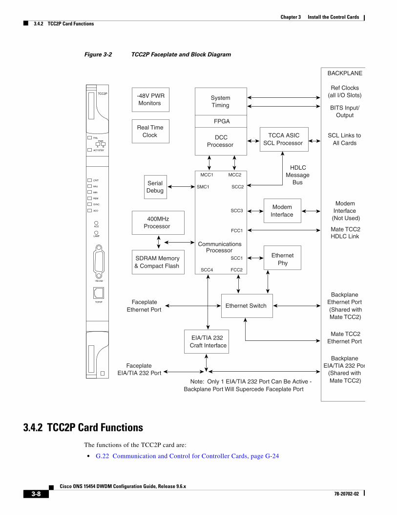
The TCC2P card supports multi-shelf management. The TCC2P card acts as a shelf controller and node controller for the ONS 15454. The TCC2P card supports up to four subtended shelves through the MS-ISC card or external switch. In a multi-shelf configuration, the TCC2P card allows the ONS 15454 node to be a node controller and does not support subtending of ONS 15454 M6 shelves.
The TCC2P card is compliant to the following standards:
• The LAN interface of the TCC2P card meets the standard Ethernet specifications by supporting a cable length of 328 ft. (100 m) at temperatures from 32 to 149 degrees Fahrenheit (0 to 65 degrees Celsius). The interfaces can operate with a cable length of 32.8 ft. (10 m) maximum at temperatures from –40 to 32 degrees Fahrenheit (–40 to 0 degrees Celsius).
• The TCC2P card is Restriction of Use of Hazardous Substances (RoHS) complaint. The RoHS regulations limit or ban the specific substances such as lead, cadmium, polybrominated biphenyl (PBB), mercury, hexavalent chromium, and polybrominated diphenyl ether (PBDE) flame retardants in a new electronic and electric equipment.
Install TCC2P cards in Slots 7 and 11 for redundancy. If the active TCC2P card fails, traffic switches to the protect TCC2P card. All TCC2P card protection switches conform to protection switching standards when the bit error rate (BER) counts are not in excess of 1 * 10 exp – 3 and completion time is less than 50 ms.
3.4.1 Faceplate and Block DiagramFigure 3-2 shows the faceplate and block diagram for the TCC2P card.
3-7Cisco ONS 15454 DWDM Configuration Guide, Release 9.6.x
78-20702-02
Chapter 3 Install the Control Cards3.4.2 TCC2P Card Functions
Figure 3-2 TCC2P Faceplate and Block Diagram
3.4.2 TCC2P Card FunctionsThe functions of the TCC2P card are:
• G.22 Communication and Control for Controller Cards, page G-24
FAIL
A
PWR
B
ACT/STBY
ACO
CRIT
MIN
REM
SYNC
RS-232
TCP/IP
MAJ
ACO
TCC2P
LAMP
BACKPLANE
Ethernet Switch
Mate TCC2Ethernet Port
BackplaneEthernet Port (Shared withMate TCC2)
SDRAM Memory& Compact Flash
FPGA
TCCA ASICSCL Processor
SerialDebug
ModemInterface
EIA/TIA 232Craft Interface
BackplaneEIA/TIA 232 Por
(Shared withMate TCC2)
FaceplateEIA/TIA 232 Port
Note: Only 1 EIA/TIA 232 Port Can Be Active -Backplane Port Will Supercede Faceplate Port
FaceplateEthernet Port
SCL Links toAll Cards
HDLCMessage
Bus
Mate TCC2HDLC Link
ModemInterface
(Not Used)400MHzProcessor
CommunicationsProcessor
SCC3
MCC1
FCC1
MCC2
FCC2SCC4
SMC1 SCC2
DCCProcessor
SystemTiming BITS Input/
Output
Ref Clocks(all I/O Slots)-48V PWR
Monitors
Real TimeClock
EthernetPhy
SCC1
3-8Cisco ONS 15454 DWDM Configuration Guide, Release 9.6.x
78-20702-02

Chapter 3 Install the Control Cards3.4.3 Related Procedures for TCC2P Card
• G.10 Timing Synchronization, page G-19
• G.23 Interface Ports, page G-25
• G.26 Database Storage, page G-27
• G.27 Redundant Controller Card Installation, page G-27
• Card level indicators—Table G-1 on page G-8 l
• Network level indicators—Table G-14 on page G-15
• Power level indicators—Table G-11 on page G-13
3.4.3 Related Procedures for TCC2P CardThe following is the list of procedures and tasks related to the configuration of the TCC2P card:
• NTP-G15 Install the Common Control Cards, page 3-35
• NTP-G18 Set Up CTC Computer for Local Craft Connection to the ONS 15454
• NTP-G17 Set Up Computer for CTC
• DLP-G43 Disable or Bypass Proxy Service Using Internet Explorer (Windows)
• DLP-G44 Disable or Bypass Proxy Service Using Mozilla (Solaris)
• DLP-G48 Create Login Node Groups
• DLP-G49 Add a Node to the Current Session or Login Group
• NTP-G22 Verify Common Card Installation, page 14-5
• NTP-G144 Provision a Multishelf Node, page 14-8
• NTP-G25 Set Battery Power Monitor Thresholds, page 14-16
• NTP-G26 Set Up CTC Network Access, page 14-17
• NTP-G143 Import the Cisco Transport Planner NE Update Configuration File, page 14-48
• NTP-G163 Upgrade Nodes in Single-Shelf Mode to Multishelf Mode, page 14-129
• NTP-G51 Verify DWDM Node Turn Up, page 16-2
• NTP-G81 Change CTC Network Access
• NTP-G146 Add a Rack, Passive Unit, or Shelf to a Multishelf Node
• NTP-G147 Delete a Passive Unit, Shelf, or Rack from a Multishelf Node
• NTP-G103 Back Up the Database, page 24-2
• NTP-G104 Restore the Database, page 24-3
• NTP-G106 Reset Cards Using CTC, page 24-13
• NTP-G105 Restore the Node to Factory Configuration, page 24-4
3.5 TCC3 Card(Cisco ONS 15454 only)
3-9Cisco ONS 15454 DWDM Configuration Guide, Release 9.6.x
78-20702-02
Chapter 3 Install the Control Cards3.5.1 Faceplate and Block Diagram
Note For TCC3 card specifications, see the “TCC3 Card Specifications” section in the Hardware Specifications document.
The Timing Communications Control Three (TCC3) card is an enhanced version of the TCC2P card. The primary enhancements include the increase in memory size and compact flash space. The TCC3 card boots up as TCC2P card in older releases and as TCC3 card from Release 9.2 onwards.
The TCC3 card performs system initialization, provisioning, alarm reporting, maintenance, diagnostics, IP address detection/resolution, SONET SOH DCC/GCC termination, and system fault detection for the ONS 15454. The TCC3 also ensures that the system maintains Stratum 3 (Telcordia GR-253-CORE) timing requirements. It monitors the supply voltage of the system.
The TCC3 card supports multi-shelf management. The TCC3 card acts as a shelf controller and node controller for the ONS 15454. The TCC3 card supports up to 50 subtended shelves through the MSM-ISC card or external switch. In a multi-shelf configuration, the TCC3 card allows the ONS 15454 node to be a node controller if an M6 shelf is subtended to it. We recommend the use of TCC3 card as a node controller when the number of subtended shelves exceeds three.
The TCC3 card is compliant with the following standards:
• The LAN interface of the TCC3 card meets the standard Ethernet specifications by supporting a cable length of 328 ft (100 m) at temperatures ranging from 32 to 149 degrees Fahrenheit (0 to 65 degrees Celsius). The interfaces can operate with a cable length of 32.8 ft (10 m) maximum at temperatures from –40 to 32 degrees Fahrenheit (–40 to 0 degrees Celsius).
• The TCC3 card is Restriction of Use of Hazardous Substances (RoHS) compliant. The RoHS regulations limit or ban the specific substances such as lead, cadmium, polybrominated biphenyl (PBB), mercury, hexavalent chromium, and polybrominated diphenyl ether (PBDE) flame retardants in a new electronic and electric equipment.
3.5.1 Faceplate and Block DiagramFigure 3-3 shows the faceplate and block diagram for the TCC3 card.
3-10Cisco ONS 15454 DWDM Configuration Guide, Release 9.6.x
78-20702-02

Chapter 3 Install the Control Cards3.5.2 TCC3 Card Functions
Figure 3-3 TCC3 Faceplate and Block Diagram
3.5.2 TCC3 Card FunctionsThe functions of the TCC3 card are:
• G.22 Communication and Control for Controller Cards, page G-24
• G.10 Timing Synchronization, page G-19
• G.23 Interface Ports, page G-25
• G.26 Database Storage, page G-27
• G.27 Redundant Controller Card Installation, page G-27
• Card level indicators—Table G-1 on page G-8
FAIL
A
PWR
B
ACT/STBY
ACO
CRIT
MIN
REM
SYNC
RS-232
TCP/IP
MAJ
ACO
TCC3
LAMP
BACKPLANE
Ethernet Switch
Mate TCCEthernet Port
BackplaneEthernet Port (Shared withMate TCC)
SDRAM Memory& Compact Flash
FPGA
TCCA FPGASCL Processor
SerialDebug
ModemInterface
EIA/TIA 232Craft Interface
BackplaneEIA/TIA 232 Port
(Shared withMate TCC)
FaceplateEIA/TIA 232 Port
Note: Only 1 EIA/TIA 232 Port Can Be Active -Backplane Port Will Supercede Faceplate Port
FaceplateEthernet Port
SCL Links toAll Cards
HDLCMessage
Bus
Mate TCCHDLC Link
ModemInterface
(Not Used)400MHz
Processor
CommunicationsProcessor
SCC3
MCC1
FCC1
MCC2
FCC2SCC4
SMC1 SCC2
DCCProcessor
SystemTiming BITS Input/
Output
Ref Clocks(all I/O Slots)-48V PWR
Monitors
Real TimeClock
EthernetPhy
SCC1
2486
63
3-11Cisco ONS 15454 DWDM Configuration Guide, Release 9.6.x
78-20702-02
Chapter 3 Install the Control Cards3.5.3 Related Procedures for TCC3 Card
• Network level indicators—Table G-14 on page G-15
• Power level indicators—Table G-13 on page G-14
3.5.3 Related Procedures for TCC3 CardThe following is the list of procedures and tasks related to the configuration of the TCC3 card:
• NTP-G15 Install the Common Control Cards, page 3-35
• NTP-G18 Set Up CTC Computer for Local Craft Connection to the ONS 15454
• NTP-G17 Set Up Computer for CTC
• DLP-G43 Disable or Bypass Proxy Service Using Internet Explorer (Windows)
• DLP-G44 Disable or Bypass Proxy Service Using Mozilla (Solaris)
• DLP-G48 Create Login Node Groups
• DLP-G49 Add a Node to the Current Session or Login Group
• NTP-G22 Verify Common Card Installation, page 14-5
• NTP-G144 Provision a Multishelf Node, page 14-8
• NTP-G25 Set Battery Power Monitor Thresholds, page 14-16
• NTP-G26 Set Up CTC Network Access, page 14-17
• NTP-G143 Import the Cisco Transport Planner NE Update Configuration File, page 14-48
• NTP-G163 Upgrade Nodes in Single-Shelf Mode to Multishelf Mode, page 14-129
• NTP-G51 Verify DWDM Node Turn Up, page 16-2
• NTP-G81 Change CTC Network Access
• NTP-G146 Add a Rack, Passive Unit, or Shelf to a Multishelf Node
• NTP-G147 Delete a Passive Unit, Shelf, or Rack from a Multishelf Node
• NTP-G103 Back Up the Database, page 24-2
• NTP-G104 Restore the Database, page 24-3
• NTP-G106 Reset Cards Using CTC, page 24-13
• NTP-G105 Restore the Node to Factory Configuration, page 24-4
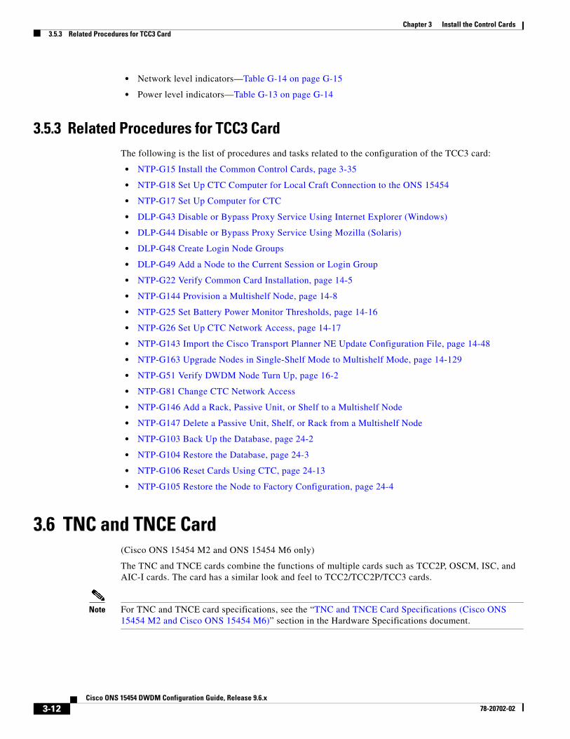
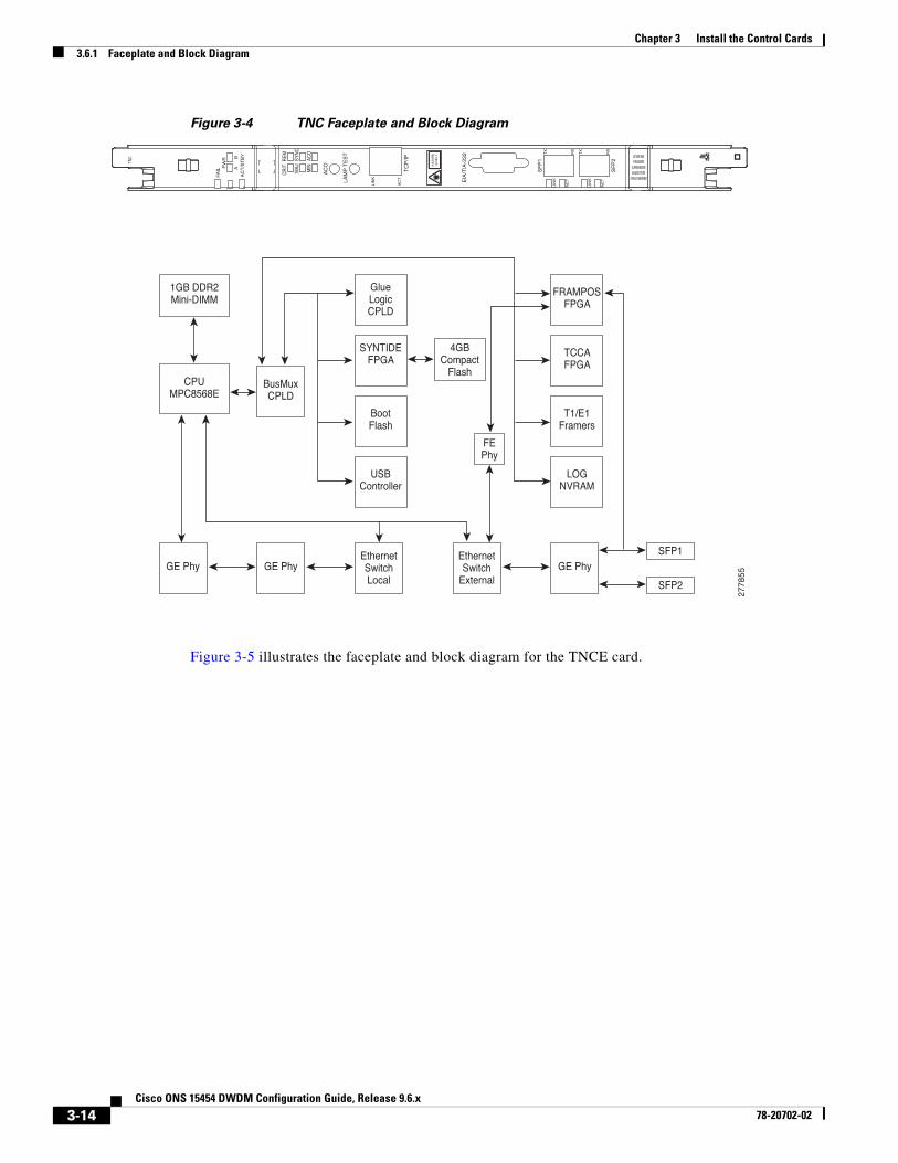
3.6 TNC and TNCE Card(Cisco ONS 15454 M2 and ONS 15454 M6 only)
The TNC and TNCE cards combine the functions of multiple cards such as TCC2P, OSCM, ISC, and AIC-I cards. The card has a similar look and feel to TCC2/TCC2P/TCC3 cards.
Note For TNC and TNCE card specifications, see the “TNC and TNCE Card Specifications (Cisco ONS 15454 M2 and Cisco ONS 15454 M6)” section in the Hardware Specifications document.
3-12Cisco ONS 15454 DWDM Configuration Guide, Release 9.6.x
78-20702-02

Chapter 3 Install the Control Cards3.6.1 Faceplate and Block Diagram
The TNC and TNCE cards are provisioned as master and slave in the 15454-M6 shelf, and as a stand-alone card in the 15454-M2 shelf. The TNC and TNCE cards serve as the processor card for the node.
On the 15454-M6 shelf, install redundant TNC and TNCE cards in slots 1 and 8. If the active TNC or TNCE card fails, system traffic switches to the redundant TNC or TNCE card. The card supports line cards from slots 2 to 7.
On the 15454-M2 shelf, install the stand-alone TNC and TNCE cards in slot 1. The TNC and TNCE cards support line cards in slots 2 and 3.
The TNC and TNCE cards monitor both the supply voltage inputs on the 15454-M6 shelf. The TNC and TNCE cards raise an alarm if one of the supply voltage inputs has a voltage out of the specified range. The 15454-M2 shelf has dual power supply.
You can insert and remove the TNC and TNCE cards even when the system is online, without impacting the system traffic.
You can upgrade the TSC or TSCE card to a TNC or TNCE card. During the upgrade, the TNC and TNCE cards do not support OSC functions such as UDC, VoIP, DCC, and timing function. However, you can still provision the SFP ports on the TNC and TNCE cards during the upgrade. The TNC/TNCE and TSC/TSCE cards cannot be inserted in the same shelf.
The TNC and TNCE cards support all the alarms supported by the TCC2P and AIC-I cards. The card adjusts the fan speed according to the temperature and reports a fan failure alarm.
Note The LAN interface of the TNC and TNCE cards meet the standard Ethernet specifications by supporting a cable length of 328 ft (100 m) at temperatures from 32 to 149 degrees Fahrenheit (0 to 65 degrees Celsius). The interfaces can operate with a cable length of 32.8 ft (10 m) maximum at temperatures from -40 to 32 degrees Fahrenheit (-40 to 0 degrees Celsius).
3.6.1 Faceplate and Block Diagram The faceplate design of the TNC and TNCE cards allow sufficient space to insert or remove cables while accessing the Ethernet and SFP ports.
The TNC and TNCE cards can be installed only in slots 1 or 8 of the ONS 15454 M6 shelf and in slot 1 of the ONS 15454 M2 shelf. The TNC and TNCE cards have an identifier on the faceplate that matches with an identifier in the shelf. A key is also provided on the backplane interface connectors as identifier in the shelf.
The TNC and TNCE cards support field-programmable gate array (FPGA) for the backplane interface. The TNC cards have two FPGA: TCCA, SYNTIDE and FRAMPOS
The TNCE cards have one FPGA: VEGA and FRAMPOS
Figure 3-4 illustrates the faceplate and block diagram for the TNC card.
3-13Cisco ONS 15454 DWDM Configuration Guide, Release 9.6.x
78-20702-02
Chapter 3 Install the Control Cards3.6.1 Faceplate and Block Diagram
Figure 3-4 TNC Faceplate and Block Diagram
Figure 3-5 illustrates the faceplate and block diagram for the TNCE card.
HA
ZA
RD
LEV
EL
1
COMPLIES WITH 21 CFR 1040.10AND 1040.11 EXCEPT FOR
DEVIATIONS PURSUANT TOLASER NOTICE No.50,DATED JUNE 24, 2007
TNC
FAIL
AC
T/S
TB
Y
AC
O
SF
P2
PW
R
AB
LAM
P T
ES
T
SF
P1
LIN
KEIA
/TIA
-232
AC
T
LIN
K
TC
P/IP
AC
T
LIN
K
AC
T
TX
RX
TX
RX
CR
ITR
EM
MAJ
SYN
C
MIN
ACO
1GB DDR2Mini-DIMM
CPUMPC8568E
GE Phy GE Phy GE PhySFP1
SFP2
BusMuxCPLD
EthernetSwitchLocal
EthernetSwitch
External
GlueLogicCPLD
SYNTIDEFPGA
BootFlash
USBController
FRAMPOSFPGA
TCCAFPGA
T1/E1Framers
LOGNVRAM
FEPhy
4GBCompact
Flash
2778
55
3-14Cisco ONS 15454 DWDM Configuration Guide, Release 9.6.x
78-20702-02
Chapter 3 Install the Control Cards3.6.2 TNC and TNCE Card Functions
Figure 3-5 TNCE Faceplate and Block Diagram
3.6.2 TNC and TNCE Card FunctionsThe functions of the TNC and TNCE cards are:
• G.22 Communication and Control for Controller Cards, page G-24
• G.28 Optical Service Channel, page G-28
• G.10 Timing Synchronization, page G-19
• G.29 MultiShelf Management, page G-28
• G.26 Database Storage, page G-27
• G.23 Interface Ports, page G-25
• G.24 External Alarms and Controls, page G-26
• G.15 Lamp Test, page G-22
• G.27 Redundant Controller Card Installation, page G-27
• Card level indicators—Table G-1 on page G-8
• Network level indicators—Table G-14 on page G-15
• Power level indicators—Table G-13 on page G-14
• Port level indicators—Table G-15 on page G-15
• TNC and TNCE SFP indicators—Table G-16 on page G-15
HA
ZA
RD
LEV
EL
1
COMPLIES WITH 21 CFR 1040.10AND 1040.11 EXCEPT FOR
DEVIATIONS PURSUANT TOLASER NOTICE No.50,DATED JUNE 24, 2007
TNCE
FAIL
AC
T/S
TB
Y
AC
O
SF
P2
PW
R
AB
LAM
P T
ES
T
SF
P1
LIN
KEIA
/TIA
-232
AC
T
LIN
K
TC
P/IP
AC
T
LIN
K
AC
T
TX
RX
TX
RX
CR
ITR
EM
MAJ
SYN
C
MIN
ACO
1GB DDR2Mini-DIMM
CPUMPC8568E
GE Phy GE Phy GE PhySFP1
SFP2
BusMuxCPLD
EthernetSwitchLocal
EthernetSwitch
External
GlueLogicCPLD
BootFlash
USBController
FRAMPOSFPGA
FPGAFPGA
T1/E1Framers
LOGNVRAM
FEPhy
CPU8378
1588 FEPHY
4GBCompact
Flash
2366
96
3-15Cisco ONS 15454 DWDM Configuration Guide, Release 9.6.x
78-20702-02

Chapter 3 Install the Control Cards3.6.3 Related Procedures for TNC and TNCE Cards
• G.30 Protection Schemes, page G-29
• G.31 Cards Supported by TNC/TNCE/TSC/TSCE, page G-29
3.6.3 Related Procedures for TNC and TNCE CardsThe following is the list of procedures and tasks related to the configuration of the TNC and TNCE cards:
• NTP-G313 Install and Configure the TNC, TNCE, TSC, or TSCE Card, page 3-42
• NTP-G17 Set Up Computer for CTC
• DLP-G43 Disable or Bypass Proxy Service Using Internet Explorer (Windows)
• DLP-G44 Disable or Bypass Proxy Service Using Mozilla (Solaris)
• DLP-G48 Create Login Node Groups
• DLP-G49 Add a Node to the Current Session or Login Group
• DLP-G41 Set Up a Windows PC for Craft Connection to an ONS 15454 Using Automatic Host Detection
• NTP-G19 Set Up a CTC Computer for a Corporate LAN Connection to the ONS 15454
• NTP-G22 Verify Common Card Installation, page 14-5
• NTP-G250 Verify Digital Image Signing (DIS) Information, page 14-6
• NTP-G279 Monitor TNC and TNCE Card Performance
• NTP-G144 Provision a Multishelf Node, page 14-8
• NTP-G25 Set Battery Power Monitor Thresholds, page 14-16
• NTP-G26 Set Up CTC Network Access, page 14-17
• NTP-G143 Import the Cisco Transport Planner NE Update Configuration File, page 14-48
• NTP-G163 Upgrade Nodes in Single-Shelf Mode to Multishelf Mode, page 14-129
• NTP-G51 Verify DWDM Node Turn Up, page 16-2
• NTP-G81 Change CTC Network Access
• NTP-G146 Add a Rack, Passive Unit, or Shelf to a Multishelf Node
• NTP-G147 Delete a Passive Unit, Shelf, or Rack from a Multishelf Node
• NTP-G103 Back Up the Database, page 24-2
• NTP-G104 Restore the Database, page 24-3
• NTP-G106 Reset Cards Using CTC, page 24-13
• NTP-G277 Provision Alarms and Controls on the TNC, TNCE, TSC, or TSCE Card
• NTP-G105 Restore the Node to Factory Configuration, page 24-4
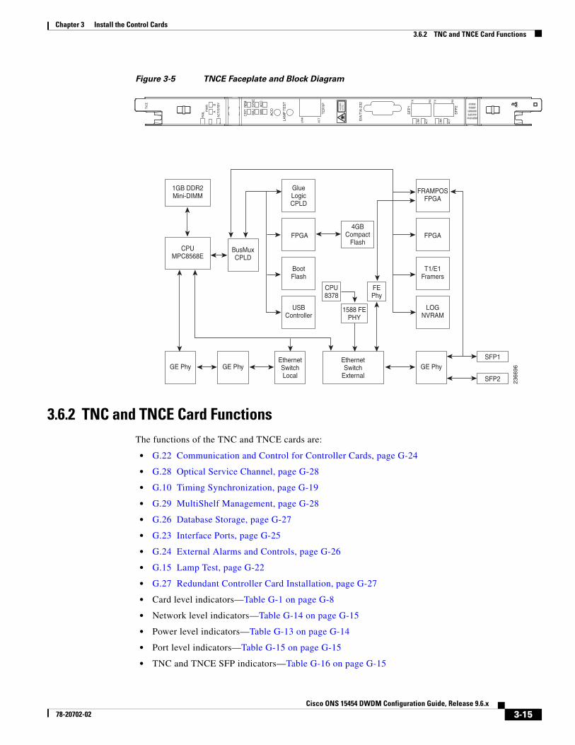
3.7 TSC and TSCE Cards(Cisco ONS 15454 M2 and ONS 15454 M6 only)
The TSC and TSCE cards combine the functions of multiple cards such as TCC2P, ISC, and AIC-I cards. The card has a similar look and feel to TCC2/TCC2P/TCC3 cards.
3-16Cisco ONS 15454 DWDM Configuration Guide, Release 9.6.x
78-20702-02

Chapter 3 Install the Control Cards3.7.1 Faceplate and Block Diagram
Note For TSC and TSCE cards specification, see the “TSC and TSCE Card Specifications (ONS 15454 M2 and ONS 15454 M6)” section in the Hardware Specifications document.
The TSC and TSCE cards are provisioned as master and slave in the ONS 15454 M6 shelf, and as a stand-alone card in the ONS 15454 M2 shelf. The TSC and TSCE cards serve as the processor card for the node.
On the ONS 15454 M6 shelf, install redundant TSC and TSCE cards in slots 1 and 8. If the active TSC or TSCE card fails, system traffic switches to the redundant TSC or TSCE card. The TSC and TSCE cards support line cards from slots 2 to 7.
On the ONS 15454 M2 shelf, install the stand-alone TSC and TSCE cards in slot 1. The TSC and TSCE cards support line cards in slots 2 and 3.
The TSC and TSCE cards monitor both the supply voltage inputs on the 15454-M6 shelf. The TSC and TSCE cards raise an alarm if one of the supply voltage inputs has a voltage out of the specified range. The 15454-M2 shelf has dual power supply.
You can insert and remove the TSC and TSCE cards even when the system is online, without impacting the system traffic.
The TSC and TSCE cards do not support optical service channel (OSC) and SFP ports.
You can upgrade the TSC or TSCE card to a TNC or TNCE card. During the upgrade, the TNC and TNCE cards do not support OSC functions such as UDC, VoIP, DCC, and timing function. However, you can still provision SFP ports on the TNC and TNCE cards during the upgrade. The TNC, TNCE, TSC, and TSCE cards cannot be inserted in the same shelf.
The TSC and TSCE cards support all the alarms supported by the TCC2P and AIC-I cards. The card adjusts the fan speed according to the temperature and reports a fan failure alarm.
Note The LAN interface of the TSC and TSCE cards meet the standard Ethernet specifications by supporting a cable length of 328 ft (100 m) at temperatures from 32 to 149 degrees Fahrenheit (0 to 65 degrees Celsius). The interfaces can operate with a cable length of 32.8 ft (10 m) maximum at temperatures from -40 to 32 degrees Fahrenheit (-40 to 0 degrees Celsius).
3.7.1 Faceplate and Block DiagramThe faceplate design of the TSC and TSCE cards allow sufficient space to insert or remove cables while accessing the Ethernet ports.
The TSC and TSCE cards can be installed only in slots 1 or 8 of the 15454-M6 shelf and in slot 1 of the 15454-M2 shelf. The TSC and TSCE cards have an identifier on the faceplate that matches with an identifier in the shelf. A key is also provided on the backplane interface connectors as identifier in the shelf.
The TSC and TSCE cards support field-programmable gate array (FPGA) for the backplane interface. The TSC cards have two FPGA: TCCA and SYNTIDE
The TSCE cards have one FPGA: VEGA
Figure 3-6 illustrates the faceplate and block diagram for the TSC card.
3-17Cisco ONS 15454 DWDM Configuration Guide, Release 9.6.x
78-20702-02
Chapter 3 Install the Control Cards3.7.2 TSC and TSCE Card Functions
Figure 3-6 TSC Faceplate and Block Diagram
Figure 3-7 illustrates the faceplate for the TSCE card.
Figure 3-7 TSCE Faceplate
3.7.2 TSC and TSCE Card FunctionsThe functions of the TSC and TSCE cards are:
• G.22 Communication and Control for Controller Cards, page G-24
• G.10 Timing Synchronization, page G-19
• G.29 MultiShelf Management, page G-28
• G.26 Database Storage, page G-27
• G.23 Interface Ports, page G-25
• G.24 External Alarms and Controls, page G-26
• G.15 Lamp Test, page G-22
• G.27 Redundant Controller Card Installation, page G-27
• Card level indicators—Table G-1 on page G-8
TSC
FAIL
AC
T/S
TB
Y
CR
ITR
EM
MAJ
SYN
C
MIN
ACO
AC
OPW
R
AB
LAM
P T
ES
T
EIA
/TIA
-232
TC
P/IP
AC
T
LIN
K
256MB DDR2Mini-DIMM
CPUMPC8568E
GE Phy GE Phy
BusMuxCPLD
EthernetSwitchLocal
EthernetSwitch
External
GlueLogicCPLD
SYNTIDEFPGA
BootFlash
USBController
TCCAFPGA
T1/E1Framers
LOGNVRAM
256MBCompact
Flash
2778
56
TSCE
FAIL
AC
T/S
TB
Y
CR
ITR
EM
MAJ
SYN
C
MIN
ACO
AC
OPW
R
AB
LAM
P T
ES
T
EIA
/TIA
-232
TC
P/IP
AC
T
LIN
K
2467
95
3-18Cisco ONS 15454 DWDM Configuration Guide, Release 9.6.x
78-20702-02

Chapter 3 Install the Control Cards3.7.3 Related Procedures for TSC and TSCE Cards
• Network level indicators—Table G-14 on page G-15
• Power level indicators—Table G-13 on page G-14
• Port level indicators—Table G-15 on page G-15
• G.30 Protection Schemes, page G-29
• G.31 Cards Supported by TNC/TNCE/TSC/TSCE, page G-29
3.7.3 Related Procedures for TSC and TSCE CardsThe following is the list of procedures and tasks related to the configuration of the TSC and TSCE cards:
• NTP-G313 Install and Configure the TNC, TNCE, TSC, or TSCE Card, page 3-42
• NTP-G17 Set Up Computer for CTC
• DLP-G43 Disable or Bypass Proxy Service Using Internet Explorer (Windows)
• DLP-G44 Disable or Bypass Proxy Service Using Mozilla (Solaris)
• DLP-G48 Create Login Node Groups
• DLP-G49 Add a Node to the Current Session or Login Group
• DLP-G41 Set Up a Windows PC for Craft Connection to an ONS 15454 Using Automatic Host Detection
• NTP-G19 Set Up a CTC Computer for a Corporate LAN Connection to the ONS 15454
• NTP-G22 Verify Common Card Installation, page 14-5
• NTP-G250 Verify Digital Image Signing (DIS) Information, page 14-6
• NTP-G144 Provision a Multishelf Node, page 14-8
• NTP-G25 Set Battery Power Monitor Thresholds, page 14-16
• NTP-G26 Set Up CTC Network Access, page 14-17
• NTP-G143 Import the Cisco Transport Planner NE Update Configuration File, page 14-48
• NTP-G163 Upgrade Nodes in Single-Shelf Mode to Multishelf Mode, page 14-129
• NTP-G51 Verify DWDM Node Turn Up, page 16-2
• NTP-G81 Change CTC Network Access
• NTP-G146 Add a Rack, Passive Unit, or Shelf to a Multishelf Node
• NTP-G147 Delete a Passive Unit, Shelf, or Rack from a Multishelf Node
• NTP-G103 Back Up the Database, page 24-2
• NTP-G104 Restore the Database, page 24-3
• NTP-G106 Reset Cards Using CTC, page 24-13
• NTP-G103 Back Up the Database, page 24-2
• NTP-G104 Restore the Database, page 24-3
• NTP-G106 Reset Cards Using CTC, page 24-13
• NTP-G277 Provision Alarms and Controls on the TNC, TNCE, TSC, or TSCE Card
• NTP-G280 Modify Threshold Settings for the TNC and TNCE Cards, page 21-123
• NTP-G105 Restore the Node to Factory Configuration, page 24-4
3-19Cisco ONS 15454 DWDM Configuration Guide, Release 9.6.x
78-20702-02

Chapter 3 Install the Control Cards3.8 Digital Image Signing
• NTP-G278 Upgrade the TSC Card to the TNC Card, page 3-48
3.8 Digital Image Signing(Cisco ONS 15454 M2 and ONS 15454 M6 only)
The DIS feature complies with the new U.S. Government Federal Information Processing Standard (FIPS) 140-3 to provide security for all software provided on the Cisco ONS 15454 M6 and ONS 15454 M2 platforms. This standard requires software to be digitally signed and verified for authenticity and integrity prior to load and execution.
DIS feature automatically provides increased protection. DIS focuses on software security and provides increased protection from attacks and threats to Cisco ONS 15454 M2 and ONS 15454 M6 products. DIS verifies software integrity and provides assurance that the software has not been tampered with or modified. Digitally signed Cisco software provides counterfeit protection.
New controller cards, such as TNC/TNCE/TSC/TSCE, provide services that authenticate the origin of the software running on the Cisco ONS 15454 M2 and Cisco ONS 15454 M6 platforms. The signage and verification process is transparent until verification fails.
3.8.1 DIS IdentificationDigitally signed software can be identified by the last three characters appended to the working version and protected version field in CTC. The DIS conventions can be viewed under the working version displayed in the Maintenance > Software tab in CTC. For example, 9.2.0 (09.20-X10C-29.09-SDA) and 9.2.0 (09.20-010C-18.18-SPA).
The significance of the three characters appended to the software version is explained in Table:
3.8.2 Related Procedures for DISTo verify DIS, see NTP-G250 Verify Digital Image Signing (DIS) Information, page 14-6.
3.9 AIC-I Card(Cisco ONS 15454 only)
Character Meaning
S (first character) Indicates that the package is signed.
P or D (second character) Production (P) or Development (D) image. Production image—Software approved for general release. Development image—development software provided under special conditions for limited use.
A (third character) This third character indicates the version of the key used for signature generation. The version changes when a key is revoked and a new key is used. The values of the version key varies from A to Z.
3-20Cisco ONS 15454 DWDM Configuration Guide, Release 9.6.x
78-20702-02

Chapter 3 Install the Control Cards3.9.1 Faceplate and Block Diagram
Note For hardware specifications, see the “AIC-I Card Specifications” section in the Hardware Specifications document.
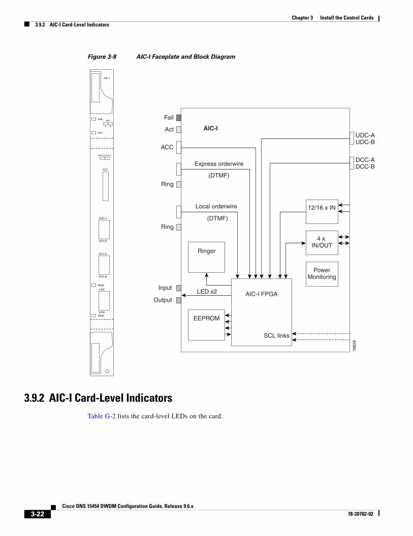
The optional Alarm Interface Controller–International (AIC-I) card provides customer-defined (environmental) alarms and controls and supports local and express orderwire. It provides 12 customer-defined input and 4 customer-defined input/output contacts. The physical connections are via the backplane wire-wrap pin terminals. If you use the additional alarm expansion panel (AEP), the AIC-I card can support up to 32 inputs and 16 outputs, which are connected on the AEP connectors. The AEP is compatible with ANSI shelves only. A power monitoring function monitors the supply voltage (–48 VDC).
3.9.1 Faceplate and Block DiagramFigure 3-8 shows the AIC-I faceplate and a block diagram of the card.
3-21Cisco ONS 15454 DWDM Configuration Guide, Release 9.6.x
78-20702-02
Chapter 3 Install the Control Cards3.9.2 AIC-I Card-Level Indicators
Figure 3-8 AIC-I Faceplate and Block Diagram
3.9.2 AIC-I Card-Level IndicatorsTable G-2 lists the card-level LEDs on the card.
AIC-I
Fail
Express orderwire
Local orderwire
EEPROM
LED x2 AIC-I FPGA
SCL links
4 x IN/OUT
PowerMonitoring
12/16 x IN
Ringer
Act
Ring
Ring
Input
Output
7882
8
FAIL
ACT
ACC
INPUT/OUTPUT
EOW
LOW
RING
AIC-1
(DTMF)
(DTMF)
UDC-AUDC-B
DCC-ADCC-B
ACC
PWR
A B
RING
DCC-B
DCC-A
UDC-B
UDC-A
3-22Cisco ONS 15454 DWDM Configuration Guide, Release 9.6.x
78-20702-02

Chapter 3 Install the Control Cards3.9.3 External Alarms and Controls
3.9.3 External Alarms and ControlsThe AIC-I card provides input/output alarm contact closures. You can define up to 12 external alarm inputs and 4 external alarm inputs/outputs (user configurable). The physical connections are made using the backplane wire-wrap pins or FMEC connections. For information about increasing the number of input/output contacts, see the “ONS 15454 ANSI Alarm Expansion Panel” section in the Cisco ONS 15454 Hardware Installation Guide.
LEDs on the front panel of the AIC-I indicate the status of the alarm lines, one LED representing all of the inputs and one LED representing all of the outputs. External alarms (input contacts) are typically used for external sensors such as open doors, temperature sensors, flood sensors, and other environmental conditions. External controls (output contacts) are typically used to drive visual or audible devices such as bells and lights, but they can control other devices such as generators, heaters, and fans.
You can program each of the twelve input alarm contacts separately. You can program each of the sixteen input alarm contacts separately. Choices include:
• Alarm on Closure or Alarm on Open
• Alarm severity of any level (Critical, Major, Minor, Not Alarmed, Not Reported)
• Service Affecting or Non-Service Affecting alarm-service level
• 63-character alarm description for CTC display in the alarm log
You cannot assign the fan-tray abbreviation for the alarm; the abbreviation reflects the generic name of the input contacts. The alarm condition remains raised until the external input stops driving the contact or you provision the alarm input.
The output contacts can be provisioned to close on a trigger or to close manually. The trigger can be a local alarm severity threshold, a remote alarm severity, or a virtual wire:
• Local NE alarm severity: A hierarchy of Not Reported, Not Alarmed, Minor, Major, or Critical alarm severities that you set to cause output closure. For example, if the trigger is set to Minor, a Minor alarm or above is the trigger.
• Remote NE alarm severity: Same as the local NE alarm severity but applies to remote alarms only.
• Virtual wire entities: You can provision any environmental alarm input to raise a signal on any virtual wire on external outputs 1 through 4 when the alarm input is an event. You can provision a signal on any virtual wire as a trigger for an external control output.
You can also program the output alarm contacts (external controls) separately. In addition to provisionable triggers, you can manually force each external output contact to open or close. Manual operation takes precedence over any provisioned triggers that might be present.
Note For ANSI shelves, the number of inputs and outputs can be increased using the AEP. The AEP is connected to the shelf backplane and requires an external wire-wrap panel.
3.9.4 OrderwireOrderwire allows a crafts person to plug a phone set into an ONS 15454 and communicate with crafts people working at other ONS 15454s or other facility equipment. The orderwire is a pulse code modulation (PCM) encoded voice channel that uses E1 or E2 bytes in section/line overhead.
3-23Cisco ONS 15454 DWDM Configuration Guide, Release 9.6.x
78-20702-02

Chapter 3 Install the Control Cards3.9.4 Orderwire
The AIC-I allows simultaneous use of both local (section overhead signal) and express (line overhead channel) orderwire channels on a SONET/SDH ring or particular optics facility. Express orderwire also allows communication via regeneration sites when the regenerator is not a Cisco device.
You can provision orderwire functions with CTC similar to the current provisioning model for DCC/GCC channels. In CTC, you provision the orderwire communications network during ring turn-up so that all NEs on the ring can reach one another. Orderwire terminations (that is, the optics facilities that receive and process the orderwire channels) are provisionable. Both express and local orderwire can be configured as on or off on a particular SONET/SDH facility. The ONS 15454 supports up to four orderwire channel terminations per shelf. This allows linear, single ring, dual ring, and small hub-and-spoke configurations. Orderwire is not protected in ring topologies such as bidirectional line switched ring (BLSR), multiplex section-shared protection ring (MS-SPRing), path protection, or subnetwork connection protection (SNCP) ring.
Caution Do not configure orderwire loops. Orderwire loops cause feedback that disables the orderwire channel.
The ONS 15454 implementation of both local and express orderwire is broadcast in nature. The line acts as a party line. Anyone who picks up the orderwire channel can communicate with all other participants on the connected orderwire subnetwork. The local orderwire party line is separate from the express orderwire party line. Up to four OC-N/STM-N facilities for each local and express orderwire are provisionable as orderwire paths.
The AIC-I supports selective dual tone multi-frequency (DTMF) dialing for telephony connectivity, which causes one AIC-I card or all ONS 15454 AIC-I cards on the orderwire subnetwork to “ring.” The ringer/buzzer resides on the AIC-I. There is also a “ring” LED that mimics the AIC-I ringer. It flashes when a call is received on the orderwire subnetwork. A party line call is initiated by pressing *0000 on the DTMF pad. Individual dialing is initiated by pressing * and the individual four-digit number on the DTMF pad.
Table 3-2 shows the pins on the orderwire connector that correspond to the tip and ring orderwire assignments.
When provisioning the orderwire subnetwork, make sure that an orderwire loop does not exist. Loops cause oscillation and an unusable orderwire channel.
Figure 3-9 shows the standard RJ-11 connectors used for orderwire ports.
Table 3-2 Orderwire Pin Assignments
RJ-11 Pin Number Description
1 Four-wire receive ring
2 Four-wire transmit tip
3 Two-wire ring
4 Two-wire tip
5 Four-wire transmit ring
6 Four-wire receive tip
3-24Cisco ONS 15454 DWDM Configuration Guide, Release 9.6.x
78-20702-02

Chapter 3 Install the Control Cards3.9.5 Power Monitoring
Figure 3-9 RJ-11 Connector
3.9.5 Power MonitoringThe AIC-I card provides a power monitoring circuit that monitors the supply voltage of –48 VDC for presence, under voltage, and over voltage.
3.9.6 User Data Channel The user data channel (UDC) features a dedicated data channel of 64 kbps (F1 byte) between two nodes in an ONS 15454 network. Each AIC-I card provides two user data channels, UDC-A and UDC-B, through separate RJ-11 connectors on the front of the AIC-I card. Each UDC can be routed to an individual optical interface in the ONS 15454.
The UDC ports are standard RJ-11 receptacles. Table 3-3 lists the UDC pin assignments.
3.9.7 Data Communications ChannelThe DCC features a dedicated data channel of 576 kbps (D4 to D12 bytes) between two nodes in an ONS 15454 network. Each AIC-I card provides two data communications channels, DCC-A and DCC-B, through separate RJ-45 connectors on the front of the AIC-I card. Each DCC can be routed to an individual optical interface in the ONS 15454.
The DCC ports are synchronous serial interfaces. The DCC ports are standard RJ-45 receptacles. Table 3-4 lists the DCC pin assignments.
6107
7
Pin 1 Pin 6
RJ-11
Table 3-3 UDC Pin Assignments
RJ-11 Pin Number Description
1 For future use
2 TXN
3 RXN
4 RXP
5 TXP
6 For future use
3-25Cisco ONS 15454 DWDM Configuration Guide, Release 9.6.x
78-20702-02

Chapter 3 Install the Control Cards3.9.8 Related Procedures for AIC-I Card
3.9.8 Related Procedures for AIC-I CardThe following is the list of procedures and tasks related to the configuration of the AIC-I card:
• NTP-G15 Install the Common Control Cards, page 3-35
• NTP-G22 Verify Common Card Installation, page 14-5
• NTP-G60 Create and Delete Overhead Circuits, page 17-87
• NTP-G72 Provision External Alarms and Controls on the Alarm Interface Controller-International Card
• NTP-G101 Modify Alarm Interface Controller–International Settings, page 21-119
3.10 MS-ISC-100T Card(Cisco ONS 15454 only)
Note For hardware specifications, see the “MS-ISC-100T Card Specifications” section in the Hardware Specifications document.
The Multishelf Internal Switch Card (MS-ISC-100T) is an Ethernet switch used to implement the multishelf LAN. It connects the node controller shelf to the network and to subtending shelves. The MS-ISC-100T must always be equipped on the node controller shelf; it cannot be provisioned on a subtending controller shelf.
The recommended configuration is to implement LAN redundancy using two MS-ISC-100T cards: one switch is connected to the Ethernet front panel port of the TCC2/TCC2P card in Slot 7, and the other switch is connected to the Ethernet front panel port of the TCC2/TCC2P card in Slot 11. The Ethernet configuration of the MS-ISC-100T card is part of the software package and is automatically loaded. The MS-ISC-100T card operates in Slots 1 to 6 and 12 to 17 on the node controller shelf; the recommended slots are Slot 6 and Slot 12.
Table 3-5 lists the MS-ISC-100T port assignments.
Table 3-4 DCC Pin Assignments
RJ-45 Pin Number Description
1 TCLKP
2 TCLKN
3 TXP
4 TXN
5 RCLKP
6 RCLKN
7 RXP
8 RXN
3-26Cisco ONS 15454 DWDM Configuration Guide, Release 9.6.x
78-20702-02

Chapter 3 Install the Control Cards3.10.1 Faceplate Diagram
Caution Shielded twisted-pair cabling should be used for inter-building applications.
3.10.1 Faceplate DiagramFigure 3-10 shows the card faceplate.
Table 3-5 MS-ISC-100T Card Port Assignments
Port Description
DCN 1and DCN 2 Connection to the network
SSC1 to SSC7 Connection to subtending shelves
NC Connection to TCC2/TCC2P using a cross-over cable
PRT Connection to the PRT port of the redundant MS-ISC-100T
3-27Cisco ONS 15454 DWDM Configuration Guide, Release 9.6.x
78-20702-02

Chapter 3 Install the Control Cards3.10.2 MS-ISC-100T Card-Level Indicators
Figure 3-10 MS-ISC-100T Faceplate
3.10.2 MS-ISC-100T Card-Level IndicatorsTable G-3 lists the card-level LEDs on the card.
3.10.3 Related Procedures for MS-ISC-100T CardThe following is the list of procedures and tasks related to the configuration of the MS-ISC-100T card:
• NTP-G15 Install the Common Control Cards, page 3-35
FAIL
ACT
MS ISC
100T
CONSOLE
1452
74
DC
2S
SC
1S
SC
2S
SC
3S
SC
4S
SC
5S
SC
6S
SC
7N
CP
RT
DC
N1
3-28Cisco ONS 15454 DWDM Configuration Guide, Release 9.6.x
78-20702-02

Chapter 3 Install the Control Cards3.11 Front Mount Electrical Connections
• NTP-G22 Verify Common Card Installation, page 14-5
• NTP-G144 Provision a Multishelf Node, page 14-8
• NTP-G163 Upgrade Nodes in Single-Shelf Mode to Multishelf Mode, page 14-129
• NTP-G146 Add a Rack, Passive Unit, or Shelf to a Multishelf Node
• NTP-G147 Delete a Passive Unit, Shelf, or Rack from a Multishelf Node
3.11 Front Mount Electrical ConnectionsThis section describes the MIC-A/P and MIC-C/T/P FMECs, which provide power, external alarm, and timing connections for the ONS 15454 ETSI shelf.
3.11.1 MIC-A/P FMEC
Note For hardware specifications, see the “MIC-A/P FMEC Specifications (ETSI only)” section in the Hardware Specifications document.
The MIC-A/P FMEC provides connection for the BATTERY B input, one of the two possible redundant power supply inputs. It also provides connection for eight alarm outputs (coming from the TCC2/TCC2P card), sixteen alarm inputs, and four configurable alarm inputs/outputs. Its position is in Slot 23 in the center of the subrack Electrical Facility Connection Assembly (EFCA) area.
The MIC-A/P FMEC has the following features:
• Connection for one of the two possible redundant power supply inputs
• Connection for eight alarm outputs (coming from the TCC2/TCC2P card)
• Connection for four configurable alarm inputs/outputs
• Connection for sixteen alarm inputs
• Storage of manufacturing and inventory data
For proper system operation, both the MIC-A/P and MIC-C/T/P FMECs must be installed in the ONS 15454 ETSI shelf.
3.11.2 Faceplate and Block DiagramFigure 3-11 shows the MIC-A/P faceplate.
Figure 3-11 MIC-A/P Faceplate
Figure 3-12 shows a block diagram of the MIC-A/P.
MIC-A/P
ALA
RM
IN/O
UT
CLEI CODE BARCODE
POWER RATING
GN
D
BA
TT
ER
Y B
CA
UTIO
NTI
GH
TEN
TH
E FA
CEP
LATE
TIG
HTE
N T
HE
FAC
EPLA
TE
SCR
EWS
WIT
H 1
.0 N
M T
OR
QU
ESC
REW
S WIT
H 1
.0 N
M T
OR
QU
E
2713
05
3-29Cisco ONS 15454 DWDM Configuration Guide, Release 9.6.x
78-20702-02

Chapter 3 Install the Control Cards3.11.2 Faceplate and Block Diagram
Figure 3-12 MIC-A/P Block Diagram
Table 3-6 shows the alarm interface pinouts on the MIC-A/P DB-62 connector.
Inventory Data(EEPROM)
6133
2
Backplane
3W3Connector
AlarmsDB62
Connector
Power
16 Alarm inputs
4 Alarm in/outputs
Table 3-6 Alarm Interface Pinouts on the MIC-A/P DB-62 Connector
Pin No. Signal Name Signal Description
1 ALMCUTOFF N Alarm cutoff, normally open ACO pair
2 ALMCUTOFF P Alarm cutoff, normally open ACO pair
3 ALMINP0 N Alarm input pair 1, reports closure on connected wires
4 ALMINP0 P Alarm input pair 1, reports closure on connected wires
5 ALMINP1 N Alarm input pair 2, reports closure on connected wires
6 ALMINP1 P Alarm input pair 2, reports closure on connected wires
7 ALMINP2 N Alarm input pair 3, reports closure on connected wires
8 ALMINP2 P Alarm input pair 3, reports closure on connected wires
9 ALMINP3 N Alarm input pair 4, reports closure on connected wires
10 ALMINP3 P Alarm input pair 4, reports closure on connected wires
11 EXALM0 N External customer alarm 1
12 EXALM0 P External customer alarm 1
13 GND Ground
14 EXALM1 N External customer alarm 2
15 EXALM1 P External customer alarm 2
16 EXALM2 N External customer alarm 3
17 EXALM2 P External customer alarm 3
18 EXALM3 N External customer alarm 4
19 EXALM3 P External customer alarm 4
20 EXALM4 N External customer alarm 5
21 EXALM4 P External customer alarm 5
22 EXALM5 N External customer alarm 6
23 EXALM5 P External customer alarm 6
24 EXALM6 N External customer alarm 7
25 EXALM6 P External customer alarm 7
3-30Cisco ONS 15454 DWDM Configuration Guide, Release 9.6.x
78-20702-02

Chapter 3 Install the Control Cards3.11.2 Faceplate and Block Diagram
26 GND Ground
27 EXALM7 N External customer alarm 8
28 EXALM7 P External customer alarm 8
29 EXALM8 N External customer alarm 9
30 EXALM8 P External customer alarm 9
31 EXALM9 N External customer alarm 10
32 EXALM9 P External customer alarm 10
33 EXALM10 N External customer alarm 11
34 EXALM10 P External customer alarm 11
35 EXALM11 N External customer alarm 12
36 EXALM11 P External customer alarm 12
37 ALMOUP0 N Normally open output pair 1
38 ALMOUP0 P Normally open output pair 1
39 GND Ground
40 ALMOUP1 N Normally open output pair 2
41 ALMOUP1 P Normally open output pair 2
42 ALMOUP2 N Normally open output pair 3
43 ALMOUP2 P Normally open output pair 3
44 ALMOUP3 N Normally open output pair 4
45 ALMOUP3 P Normally open output pair 4
46 AUDALM0 N Normally open Minor audible alarm
47 AUDALM0 P Normally open Minor audible alarm
48 AUDALM1 N Normally open Major audible alarm
49 AUDALM1 P Normally open Major audible alarm
50 AUDALM2 N Normally open Critical audible alarm
51 AUDALM2 P Normally open Critical audible alarm
52 GND Ground
53 AUDALM3 N Normally open Remote audible alarm
54 AUDALM3 P Normally open Remote audible alarm
55 VISALM0 N Normally open Minor visual alarm
56 VISALM0 P Normally open Minor visual alarm
57 VISALM1 N Normally open Major visual alarm
58 VISALM1 P Normally open Major visual alarm
59 VISALM2 N Normally open Critical visual alarm
60 VISALM2 P Normally open Critical visual alarm
Table 3-6 Alarm Interface Pinouts on the MIC-A/P DB-62 Connector (continued)
Pin No. Signal Name Signal Description
3-31Cisco ONS 15454 DWDM Configuration Guide, Release 9.6.x
78-20702-02

Chapter 3 Install the Control Cards3.11.3 MIC-C/T/P FMEC
3.11.3 MIC-C/T/P FMEC
Note For hardware specifications, see the “MIC-C/T/P FMEC Specifications (ETSI only)” section in the Hardware Specifications document.
The MIC-C/T/P FMEC provides connection for the BATTERY A input, one of the two possible redundant power supply inputs. It also provides connection for system management serial port, system management LAN port, modem port (for future use), and system timing inputs and outputs. Install the MIC-C/T/P in Slot 24.
The MIC-C/T/P FMEC has the following features:
• Connection for one of the two possible redundant power supply inputs
• Connection for two serial ports for local craft/modem (for future use)
• Connection for one LAN port
• Connection for two system timing inputs
• Connection for two system timing outputs
• Storage of manufacturing and inventory data
For proper system operation, both the MIC-A/P and MIC-C/T/P FMECs must be installed in the shelf.
3.11.4 Faceplate and Block DiagramFigure 3-13 shows the MIC-C/T/P FMEC faceplate.
Figure 3-13 MIC-C/T/P Faceplate
Figure 3-14 shows a block diagram of the MIC-C/T/P.
61 VISALM3 N Normally open Remote visual alarm
62 VISALM3 P Normally open Remote visual alarm
Table 3-6 Alarm Interface Pinouts on the MIC-A/P DB-62 Connector (continued)
Pin No. Signal Name Signal Description
MIC-C/T/P
CLEI CODE BARCODE
POWER RATING
GN
D
BA
TT
ER
Y A
TIMIN
G A
IN
TIMIN
G B
O
UT
CA
UTIO
NTI
GH
TEN
TH
E FA
CEP
LATE
TIG
HTE
N T
HE
FAC
EPLA
TE
SCR
EWS
WIT
H 1
.0 N
M T
OR
QU
ESC
REW
S WIT
H 1
.0 N
M T
OR
QU
E
2713
06
LAN
AU
X
TE
RM A
CT
LIN
K
3-32Cisco ONS 15454 DWDM Configuration Guide, Release 9.6.x
78-20702-02

Chapter 3 Install the Control Cards Control Card Reset
Figure 3-14 MIC-C/T/P Block Diagram
The MIC-C/T/P FMEC has one pair of LEDs located on the RJ45 LAN connector. The green LED is on when a link is present, and the amber LED is on when data is being transferred.
Control Card ResetYou can soft reset the control card by using CTC or by physically resetting the card (a hard reset). A soft reset reboots the control card and reloads the operating system and the application software. Additionally, a hard reset temporarily removes power from the control card and clears all the buffer memory.
You can apply a soft reset from CTC to either an active or standby control card without affecting traffic. If you need to perform a hard reset on an active control card, put the control card into standby mode first by performing a soft reset.
Note Hard reset can also be performed on the TNC/TNCE/TSC/TSCE card through CTC and TL1 interface. Before performing the hard reset, bring the TNC/TNCE/TSC/TSCE card to maintenance mode.
When you reset the standby control card, the system traffic is not affected. When you reset the active control card, traffic switches to the standby card if the standby card is present and in the ready standby state. If the standby card is not in the ready standby state, traffic does not switch, and results in loss of system traffic and management connectivity until the card reboots completely.
Caution When you reset the TNC/TNCE/TSC/TSCE card on the ONS 15454 or 15454-M6 shelves in simplex control mode, loss of management connectivity happens until the card reboots. The system traffic loss may occur depending on the line card and traffic type.
Note (Cisco ONS 15454 shelf) When a CTC reset is performed on an active TCC2/TCC2P/TCC3 card, the AIC-I card goes through an initialization process and also resets because it is controlled by the active TCC2/TCC2P/TCC3 card.
Inventory Data(EEPROM)
6133
4
Backplane
3W3connector
Power
RJ-45connectors
System management serial ports
RJ-45connectors
System management LAN
4 coaxialconnectors Timing 2 x in / 2 x out
3-33Cisco ONS 15454 DWDM Configuration Guide, Release 9.6.x
78-20702-02
Chapter 3 Install the Control Cards Control Card Database
Control Card DatabaseWhen dual control cards are installed in the ONS 15454, 15454-M2, or 15454-M6 shelves, each control card hosts a separate database; therefore, the protect card database is available if the database on the working control card fails. You can also store a backup version of the database on the workstation running CTC. This operation should be part of a regular ONS 15454, 15454-M2, or 15454-M6 maintenance program at approximately weekly intervals, and should also be completed when preparing ONS 15454, 15454-M2, or 15454-M6 for a pending natural disaster, such as a flood or fire.
The TNC and TNCE cards provide 4 GB of nonvolatile database storage for communication, provisioning, and system control. This allows full database recovery during power failure.
The configuration details are stored in the database of the control card. The database restore from a TNC and TNCE cards to a TSC and TSCE cards or vice versa is not supported.
Note The following parameters are not backed up and restored: node name, IP address, mask and gateway, and Internet Inter-ORB Protocol (IIOP) port. If you change the node name and then restore a backed up database with a different node name, the circuits map to the new node name. We recommend keeping a record of the old and new node names.
3.12 Procedures for Control CardsThe procedures described below explain how to install the control cards needed for the Cisco ONS 15454, Cisco ONS 15454 M2, and Cisco ONS 15454 M6 platforms.
3.12.1 Before You BeginBefore performing any of the following procedures, investigate all alarms and clear any trouble conditions. Refer to the Cisco ONS 15454 DWDM Troubleshooting Guide as necessary.
This section lists the chapter procedures (NTPs). Turn to a procedure for applicable tasks (DLPs).
• NTP-G15 Install the Common Control Cards, page 3-35—Complete this procedure to install the control cards needed for the ONS 15454 platform.
• NTP-G313 Install and Configure the TNC, TNCE, TSC, or TSCE Card, page 3-42—Complete this procedure to install the control cards needed for the ONS 15454 M2 and ONS 15454 M6 platforms.
3-34Cisco ONS 15454 DWDM Configuration Guide, Release 9.6.x
78-20702-02

Chapter 3 Install the Control Cards3.12.1 Before You Begin
NTP-G15 Install the Common Control Cards
Warning During this procedure, wear grounding wrist straps to avoid ESD damage to the card. Do not directly touch the backplane with your hand or any metal tool, or you could shock yourself. Statement 94
Caution Always use the supplied ESD wristband when working with a powered ONS 15454. For detailed instructions on how to wear the ESD wristband, refer to the Electrostatic Discharge and Grounding Guide for Cisco CPT and Cisco ONS Platforms.
Note If protective clips are installed on the backplane connectors of the cards, remove the clips before installing the cards.
Note If you install a card incorrectly, the FAIL LED flashes continuously.
Step 1 (ONS 15454 only) Complete the “DLP-G33 Install the TCC2, TCC2P, or TCC3 Card” task on page 3-36.
Note If you install the wrong card in a slot, see the NTP-G107 Remove Permanently or Remove and Replace DWDM Cards.
Step 2 (ONS 15454 only) Complete the “DLP-G34 Install the AIC-I Card” task on page 3-39, if necessary.
Step 3 (ONS 15454 only) Complete the “DLP-G309 Install the MS-ISC-100T Card” task on page 3-40, if necessary.
Stop. You have completed this procedure.
Purpose This procedure describes how to install the control cards needed for the ONS 15454 platform.
Tools/Equipment Redundant TCC2/TCC2P/TCC3 cards on ONS 15454 shelf (required)
AIC-I card (optional)
MS-ISC-100T (optional; for multishelf node configurations)
Prerequisite Procedures Following procedures in the Cisco ONS 15454 Hardware Installation Guide:
• “NTP-G7 Install the Power and Ground”
• “NTP-G14 Install DWDM Equipment”
Required/As Needed Required
Onsite/Remote Onsite
Security Level Provisioning or higher
3-35Cisco ONS 15454 DWDM Configuration Guide, Release 9.6.x
78-20702-02

Chapter 3 Install the Control CardsDLP- G33 Install the TCC2, TCC2P, or TCC3 Card
DLP-G33 Install the TCC2, TCC2P, or TCC3 Card
Caution Do not remove a TCC2/TCC2P/TCC3 card during the software transfer process, which is indicated by alternate flashing FAIL and ACT/STBY LEDs. Removing a TCC2/TCC2P/TCC3 during the software transfer process will corrupt the system memory.
Note Allow each card to boot completely before installing the next card.
Step 1 Open the latches/ejectors of the first TCC2/TCC2P/TCC3 card that you will install.
Step 2 Use the latches/ejectors to firmly slide the card along the guide rails until the card plugs into the receptacle at the back of the slot (Slot 7 or 11).
Note In Step 4, you will be instructed to watch the LED activity (sequence) on the front of the TCC2/TCC2P/TCC3 card. This activity begins immediately after you close the latches in Step 3.
Step 3 Verify that the card is inserted correctly and close the latches/ejectors on the card.
Note It is possible to close the latches/ejectors when the card is not completely plugged into the back panel of the shelf. Ensure that you cannot insert the card any farther.
If you insert a card into a slot provisioned for a different card, all LEDs turn off.
Step 4 As needed, go to Step a to verify the LED activity on the TCC2 card. For the TCC2P go to Step b. For the TCC3 card go to Step c.
a. For the TCC2 card:
• All LEDs turn on briefly. The red FAIL LED and the yellow ACT/STBY LED turn on for about 15 seconds. (For TCC3 card it takes around 20 to 25 seconds)
• The red FAIL LED and the green ACT/STBY LED turn on for about 40 seconds.
• The red FAIL LED blinks for about 15 seconds.
• The red FAIL LED turns on for about 15 seconds. All LEDs turn on for about 3 seconds before turning off for about 3 seconds.
• Both green PWR LEDs turn on for 10 seconds. The PWR LEDs then turn red for 2 to 3 minutes before going to steady green.
Purpose This task installs redundant TCC2/TCC2P/TCC3 cards. The first card you install in the ONS 15454 must be a TCC2/TCC2P/TCC3 card, and it must initialize before you install any cross-connect or traffic cards. Cross-connect cards are only required in hybrid nodes.
Tools/Equipment Two TCC2/TCC2P/TCC3 cards
Prerequisite Procedures None
Required/As Needed Required
Onsite/Remote Onsite
Security Level None
3-36Cisco ONS 15454 DWDM Configuration Guide, Release 9.6.x
78-20702-02

Chapter 3 Install the Control CardsDLP- G33 Install the TCC2, TCC2P, or TCC3 Card
• While the PWR LEDs are red for two to three minutes, the ACT/STBY turn on.
• The boot-up process is complete when the PWR LEDs turn green and the ACT/STBY remains on. (The ACT/STBY LED will be green if this is the first TCC2 card installed, and amber if this is the second TCC2 card installed.)
Note It might take up to four minutes for the A and B power alarms to clear.
Note Alarm LEDs might be on; disregard alarm LEDs until you are logged into CTC and can view the Alarms tab.
Note If you are logged into CTC, the SFTWDOWN alarm might appear as many as two times while the TCC2 card initializes. The alarm should clear after the card completely boots.
Note If the FAIL LED is on continuously, see the tip in Step 8 about the TCC2 card automatic upload.
b. For the TCC2P card:
• All LEDs turn on briefly. The red FAIL LED, the yellow ACT/STBY LED, the green SYNC LED, and the green ACO LED turn on for about 15 seconds.
• The red FAIL LED and the green ACT/STBY LED turn on for about 30 seconds.
• The red FAIL LED blinks for about 3 seconds.
• The red FAIL LED turns on for about 15 seconds.
• The red FAIL LED blinks for about 10 seconds and then becomes solid.
• All LEDs (including the CRIT, MAJ, MIN, REM, SYNC, and ACO LEDs) blink once and turn off for about 5 seconds.
• Both green PWR LEDs turn on for 10 seconds. The PWR LEDs then turn red for 2 to 3 minutes before going to steady green. During this time, the ACT/STBY, MJ, and MN LEDs might turn on, followed by the SNYC LED briefly.
• The boot-up process is complete when the PWR LEDs turn green and the yellow ACT/STBY remains on. (The ACT/STBY LED will be green if this is the first TCC2P card installed, and yellow if this is the second TCC2P card installed.)
Note It might take up to three minutes for the A and B power alarms to clear.
Note Alarm LEDs might be on; disregard alarm LEDs until you are logged into CTC and can view the Alarms tab.
Note If you are logged into CTC, the SFTWDOWN alarm might appear as many as two times while the TCC2P card initializes. The alarm should clear after the card completely boots.
3-37Cisco ONS 15454 DWDM Configuration Guide, Release 9.6.x
78-20702-02

Chapter 3 Install the Control CardsDLP- G33 Install the TCC2, TCC2P, or TCC3 Card
Note If the FAIL LED is on continuously, see the tip in Step 8 about the TCC2P card automatic upload.
c. For the TCC3 card:
• All LEDs turn on briefly. The red FAIL LED, the yellow ACT/STBY LED, the green SYNC LED, and the green ACO LED turn on for about 25 seconds.
• The red FAIL LED and the green ACT/STBY LED turn on for about 15 seconds.
• The red FAIL LED blinks for about 3 seconds.
• The red FAIL LED turns on for about 60 seconds.
• The red FAIL LED blinks for about 15 seconds and then becomes solid (the LED is turned on for about 20 seconds).
• All LEDs (including the CRIT, MAJ, MIN, REM, SYNC, and ACO LEDs) blink once and turn off for about 5 seconds.
• Both green PWR LEDs turn on for 10 seconds. The PWR LEDs then turn red for 2 to 3 minutes before going to steady green. During this time, the ACT/STBY, MJ, and MN LEDs might turn on, followed by the SNYC LED briefly.
• The boot-up process is complete when the PWR LEDs turn green and the yellow ACT/STBY remains on. (The ACT/STBY LED will be green if this is the first TCC3 card installed, and yellow if this is the second TCC3 card installed.)
Note It might take up to three minutes for the A and B power alarms to clear.
Note Alarm LEDs might be on; disregard alarm LEDs until you are logged into CTC and can view the Alarms tab.
Note If you are logged into CTC, the SFTWDOWN alarm might appear as many as two times while the TCC3 card initializes. The alarm should clear after the card completely boots.
Note If the FAIL LED is on continuously, see the tip in Step 8 about the TCC3 card automatic upload.
Step 5 Verify that the ACT/STBY LED is green if this is the first powered-up TCC2/TCC2P/TCC3 card installed, or yellow for standby if this is the second powered-up TCC2/TCC2P/TCC3. The IP address, temperature of the node, and time of day appear on the LCD. The default time and date is 12:00 AM, January 1, 1970.
Step 6 The LCD cycles through the IP address (the default is 192.1.0.2), node name, and software version. Verify that the correct software version is shown on the LCD. The software text string indicates the node type (SDH or SONET) and software release. (For example: SDH 09.20-05L-20.10 indicates it is an SDH software load, Release 9.2. The numbers following the release number do not have any significance.)
Step 7 If the LCD shows the correct software version, continue with Step 8. If the LCD does not show the correct software version, refer to your next level of technical support, upgrade the software, or remove the TCC2/TCC2P/TCC3 card and install a replacement card.
3-38Cisco ONS 15454 DWDM Configuration Guide, Release 9.6.x
78-20702-02

Chapter 3 Install the Control CardsDLP- G34 Install the AIC-I Card
Refer to the release-specific software upgrade document to replace the software. To replace the TCC2/TCC2P/TCC3 card, refer to the Cisco ONS 15454 DWDM Troubleshooting Guide.
Step 8 Repeat Steps 1 through 7 for the redundant TCC2/TCC2P/TCC3 card. If both TCC2/TCC2P/TCC3 cards are already installed, proceed to Step 9.
Tip If you install a standby TCC2/TCC2P/TCC3 card that has a different software version than the active TCC2/TCC2P/TCC3 card, the newly installed standby TCC2/TCC2P/TCC3 card automatically copies the software version from the active TCC2/TCC2P/TCC3 card. You do not need to do anything in this situation. However, the loading TCC2/TCC2P/TCC3 card does not boot up in the normal manner. When the standby card is first inserted, the LEDs follow most of the normal boot-up sequence. However, after the red FAIL LED turns on for about 5 seconds, the FAIL LED and the ACT/STBY LED begin to flash alternately for up to 30 minutes while the new software loads onto the active TCC2/TCC2P/TCC3 card. After loading the new software, the upgraded TCC2/TCC2P/TCC3 card’s LEDs repeat the appropriate bootup sequence, and the amber ACT/STBY LED turns on.
Note If you insert a card into a slot provisioned for a different card, all LEDs turn off.
Note Alarm LEDs might be on; disregard alarm LEDs until you are logged into CTC and can view the Alarms tab.
Step 9 Return to your originating procedure (NTP).
DLP-G34 Install the AIC-I Card
Note When installing cards, allow each card to boot completely before installing the next card.
Step 1 Open the latches/ejectors on the card.
Step 2 Use the latches/ejectors to firmly slide the card along the guide rails in Slot 9 until the card plugs into the receptacle at the back of the slot.
Step 3 Verify that the card is inserted correctly and close the latches/ejectors on the card.
Purpose This task installs the AIC-I card. The AIC-I card provides connections for external alarms and controls (environmental alarms).
Tools/Equipment AIC-I card
Prerequisite Procedures DLP-G33 Install the TCC2, TCC2P, or TCC3 Card, page 3-36
Required/As Needed As needed
Onsite/Remote Onsite
Security Level None
3-39Cisco ONS 15454 DWDM Configuration Guide, Release 9.6.x
78-20702-02

Chapter 3 Install the Control CardsDLP- G309 Install the MS-ISC-100T Card
Note It is possible to close the latches/ejectors when the card is not completely plugged into the backplane. Ensure that you cannot insert the card any further.
Step 4 Verify the following:
• The red FAIL LED blinks for up to 10 seconds.
Note If the red FAIL LED does not turn on, check the power.
• The PWR A and PWR B LEDs become red, the two INPUT/OUTPUT LEDs become amber, and the ACT LED turns green for approximately 5 seconds.
• The PWR A and PWR B LEDs turn green, the INPUT/OUTPUT LEDs turn off, and the green ACT LED remains on.
Note It might take up to 3 minutes for the PWR A and PWR B LEDs to update.
Note If you insert a card into a slot provisioned for a different card, no LEDs turn on.
Note If the red FAIL LED is on continuously or the LEDs act erratically, the card is not installed properly. Remove the card and repeat Steps 1 to 4.
Step 5 Return to your originating procedure (NTP).
DLP-G309 Install the MS-ISC-100T Card
Note When installing cards, allow each card to boot completely before installing the next card.
Purpose This task installs redundant MS-ISC-100T cards. The MS-ISC-100T card is required for a multishelf node configuration. It provides LAN redundancy on the node controller shelf. An alternative to using the MS-ISC-100T card is the Cisco Catalyst 2950, although Cisco recommends using the MS-ISC-100T. For more information on the Catalyst 2950 installation, refer to the Catalyst 2950 product documentation.
Tools/Equipment MS-ISC-100T card (2)
Prerequisite Procedures DLP-G33 Install the TCC2, TCC2P, or TCC3 Card, page 3-36
Required/As Needed As needed
Onsite/Remote Onsite
Security Level None
3-40Cisco ONS 15454 DWDM Configuration Guide, Release 9.6.x
78-20702-02

Chapter 3 Install the Control CardsDLP- G309 Install the MS-ISC-100T Card
Note The MS-ISC-100T is not supported in a subtended shelf.
Step 1 Open the latches/ejectors on the card.
Step 2 Use the latches/ejectors to firmly slide the card along the guide rails into the appropriate slot in the node controller shelf until the card plugs into the receptacle at the back of the slot. The card can be installed in any slot from Slot 1 to 6 or 12 to 17. Cisco recommends that you install the MS-ISC-100T cards in Slot 6 and Slot 12.
Step 3 Verify that the card is inserted correctly and close the latches/ejectors on the card.
Note It is possible to close the latches/ejectors when the card is not completely plugged into the backplane. Ensure that you cannot insert the card any further.
Step 4 Verify the LED activity:
• The red FAIL LED blinks for 35 to 45 seconds.
• The red FAIL LED turns on for 15 to 20 seconds.
• The red FAIL LED blinks for approximately 3 minutes.
• The red FAIL LED turns on for approximately 6 minutes.
• The green ACT or ACT/STBY LED turns on. The SF LED can persist until all card ports connect to their far end counterparts and a signal is present.
Note If the red FAIL LED does not turn on, check the power.
Note If you insert a card into a slot provisioned for a different card, all LEDs turn off.
Step 5 Repeat Steps 1 through 4 for the redundant MS-ISC-100T card.
Step 6 Return to your originating procedure (NTP).
3-41Cisco ONS 15454 DWDM Configuration Guide, Release 9.6.x
78-20702-02

Chapter 3 Install the Control CardsDLP- G309 Install the MS-ISC-100T Card
NTP-G313 Install and Configure the TNC, TNCE, TSC, or TSCE Card
Warning During this procedure, wear grounding wrist straps to avoid ESD damage to the card. Do not directly touch the backplane with your hand or any metal tool, or you could shock yourself. Statement 94
Caution Always use the supplied ESD wristband when working with a powered ONS 15454 M2 and ONS 15454 M6 shelf assemblies. For detailed instructions on how to wear the ESD wristband, refer to the Electrostatic Discharge and Grounding Guide for Cisco CPT and Cisco ONS Platforms.
Note If you install a card incorrectly, the FAIL LED flashes continuously.
Step 1 Complete the “DLP-G604 Install the TNC, TNCE, TSC, or TSCE Card” task on page 3-43.
Note If you install the wrong card in a slot, see the NTP-G107 Remove Permanently or Remove and Replace DWDM Cards.
Step 2 Complete the “DLP-G605 Provision PPM and Port for the TNC and TNCE Cards” task on page 3-46.
Step 3 Complete the “DLP-G606 Configure UDC and VoIP for the TNC and TNCE Cards” task on page 3-46.
Step 4 Complete the “DLP-G774 Change the Frame Type on the OSC” task on page 3-47
Stop. You have completed this procedure.
Purpose This procedure describes how to install and configure the TNC, TNCE, TSC, or TSCE card. TNC, TNCE, TSC, and TSCE cards are the control cards needed for the ONS 15454 M2 and ONS 15454 M6 platforms.
Tools/Equipment Redundant TNC/TNCE/TSC/TSCE cards on ONS 15454 M6 shelf (required)
Stand-alone TNC/TNCE/TSC/TSCE card on ONS 15454 M2 shelf (required)
Prerequisite Procedures Following procedures in the Cisco ONS 15454 Hardware Installation Guide:
• “NTP-G271 Install the Power and Ground to the ONS 15454 M2 Shelf”
• “NTP-G14 Install DWDM Equipment”
Required/As Needed Required
Onsite/Remote Onsite
Security Level Provisioning or higher
3-42Cisco ONS 15454 DWDM Configuration Guide, Release 9.6.x
78-20702-02

Chapter 3 Install the Control CardsDLP- G604 Install the TNC, TNCE, TSC, or TSCE Card
DLP-G604 Install the TNC, TNCE, TSC, or TSCE Card
Note The ONS 15454 M2 shelf supports stand-alone control cards such as TNC, TSC, TNCE, or TSCE. During replacement or removal of the control card, ensure that the optical fibers are not disturbed. The fibers must be correctly routed in the retention feature mounted on the front side of the shelf.
Caution Do not remove the TNC/TNCE/TSC/TSCE cards during the software installation process, which is indicated by alternate flashing FAIL and ACT/STBY LEDs. Removing the TNC/TNCE/TSC/TSCE cards during the software installation process will corrupt the system memory.
Note Allow each TNC/TNCE/TSC/TSCE card to boot completely before installing the redundant TNC/TNCE/TSC/TSCE card.
Note On the ONS 15454 M6 shelf, install the TNC/TNCE/TSC/TSCE cards in slots 1 and 8 for redundancy. On the ONS 15454 M2 shelf, install the stand-alone TNC/TNCE/TSC/TSCE card in slot 1. For more information, see the “Card Slot Requirements” section in the Cisco ONS 15454 Hardware Installation Guide.
Note You cannot insert the TNC/TNCE/TSC/TSCE cards in other slots due to mechanical constraints. To identify the card slot, match the symbol placed on the lower side of the card front panel with the symbol in the shelf.
Caution To achieve redundancy, two TNC and TNCE cards or two TSC and TSCE cards must be installed in the ONS 15454 M6 shelf. Do not install one TNC or TNCE card and a redundant TSC or TSCE card in the same shelf.
Purpose (ONS 15454 M2 and ONS 15454 M6 only) This task installs redundant TNC/TNCE/TSC/TSCE cards on the ONS 15454 M6 shelf and a stand-alone TNC/TNCE/TSC/TSCE card on the ONS 15454 M2 shelf. Install and initialize the TNC/TNCE/TSC/TSCE card before installing any other line cards into the shelf assemblies. On the ONS 15454 M6 shelf, install the TNC/TNCE/TSC/TSCE cards in slots 1 and 8 for redundancy. On the ONS 15454 M2 shelf, install the stand-alone TNC/TNCE/TSC/TSCE card in slot 1.
Tools/Equipment Two TNC/TNCE/TSC/TSCE cards for the ONS 15454 M6 shelf and one TNC/TNCE/TSC/TSCE card for the ONS 15454 M2 shelf
Prerequisite Procedures None
Required/As Needed Required
Onsite/Remote Onsite
Security Level None
3-43Cisco ONS 15454 DWDM Configuration Guide, Release 9.6.x
78-20702-02

Chapter 3 Install the Control CardsDLP- G604 Install the TNC, TNCE, TSC, or TSCE Card
Step 1 Open the latches/ejectors of the first TNC/TNCE/TSC/TSCE card that you will install.
Step 2 Use the latches/ejectors to firmly slide the card horizontally along the guide rails until the card plugs into the receptacle at the back of the slot (slot 1 or 8 in the ONS 15454 M6 shelf and slot 1 in the ONS 15454 M2 shelf).
Step 3 Verify that the card is inserted correctly, and close the latches/ejectors on the card.
If you insert a card into a slot assigned for a different card, all LEDs turn off.
Step 4 As needed, verify the LED activity on the TNC/TNCE/TSC/TSCE card.
• The red FAIL LED, PWR LED turn on briefly.
• The red FAIL LED turns on for about 10 seconds.
• The red FAIL LED and the amber ACT/STBY LED turn on for about 30 seconds.
• The red FAIL LED blinks for about 10 seconds.
• The red FAIL LED turns on for about 15 seconds.
• All the LEDs including the CRIT, MAJ, MIN, REM, SYNC, and ACO LEDs blink once and turn off for about 10 seconds.
• ACT/STBY LED blinks for about 1 second.
• All the LEDs including the CRIT, MAJ, MIN, REM, SYNC, and ACO LEDs turn off for about 10 seconds.
• The ACT/STBY, ACO, and PWR LEDs turn on.
• The boot-up process is complete when the PWR LEDs turn green and the amber ACT/STBY remains on. The ACT/STBY LED turns green if this is the first TNC/TNCE/TSC/TSCE card installed, and amber if this is the second TNC/TNCE/TSC/TSCE card installed.
Note It might take up to four minutes for the power alarms to clear.
Note Alarm LEDs might be on. After completing the TNC/TNCE/TSC/TSCE card installation, log in to CTC and click the Alarms tab to display the alarms raised on the card. For procedure to clear the alarm, see the Cisco ONS DWDM Troubleshooting Guide.
Note During the TNC/TNCE/TSC/TSCE card initialization, the SFTWDOWN alarm appears twice. The alarm clears after the TNC/TNCE/TSC/TSCE card boots completely.
Note If the FAIL LED is on continuously, see the tip in Step 8 about the TNC/TNCE/TSC/TSCE card automatic upload.
Figure 3-15 illustrates the installation of TNC and TNCE cards on ONS 15454 M6 shelf.
3-44Cisco ONS 15454 DWDM Configuration Guide, Release 9.6.x
78-20702-02
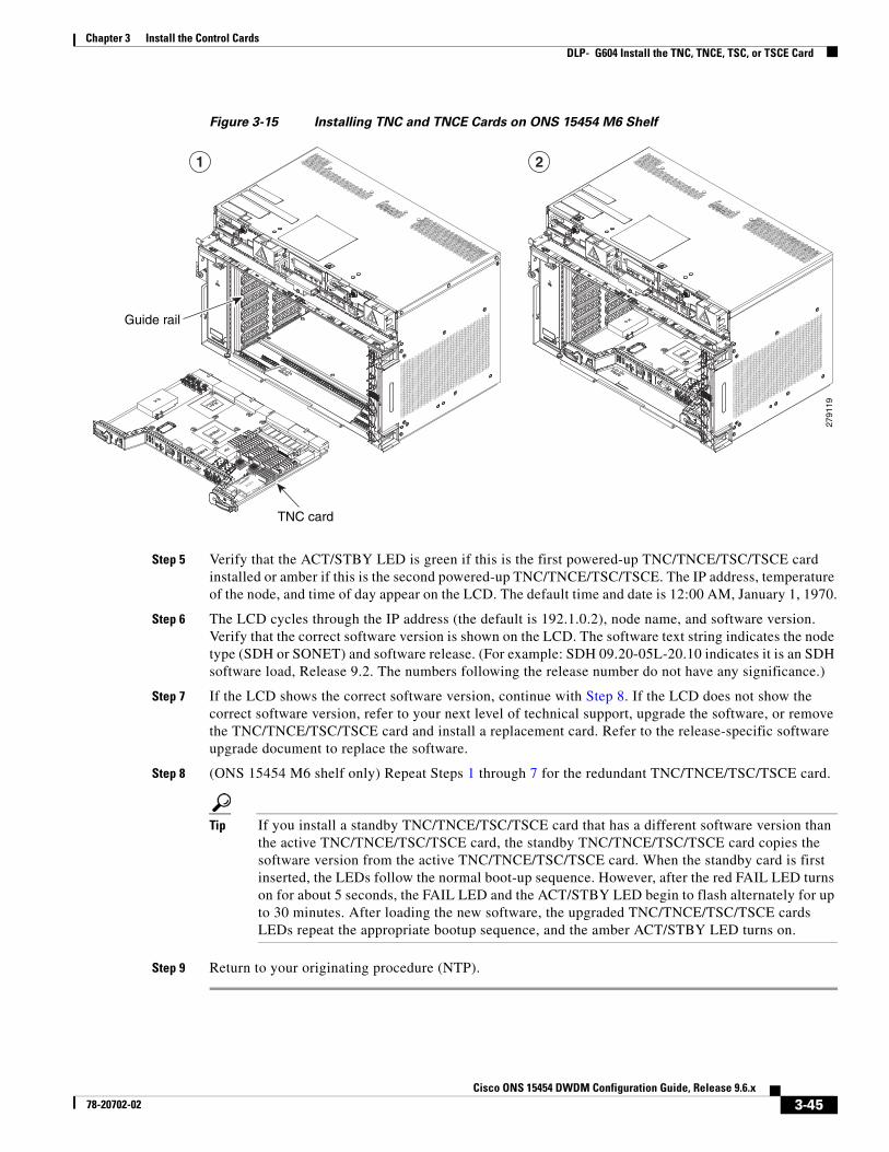
Chapter 3 Install the Control CardsDLP- G604 Install the TNC, TNCE, TSC, or TSCE Card
Figure 3-15 Installing TNC and TNCE Cards on ONS 15454 M6 Shelf
Step 5 Verify that the ACT/STBY LED is green if this is the first powered-up TNC/TNCE/TSC/TSCE card installed or amber if this is the second powered-up TNC/TNCE/TSC/TSCE. The IP address, temperature of the node, and time of day appear on the LCD. The default time and date is 12:00 AM, January 1, 1970.
Step 6 The LCD cycles through the IP address (the default is 192.1.0.2), node name, and software version. Verify that the correct software version is shown on the LCD. The software text string indicates the node type (SDH or SONET) and software release. (For example: SDH 09.20-05L-20.10 indicates it is an SDH software load, Release 9.2. The numbers following the release number do not have any significance.)
Step 7 If the LCD shows the correct software version, continue with Step 8. If the LCD does not show the correct software version, refer to your next level of technical support, upgrade the software, or remove the TNC/TNCE/TSC/TSCE card and install a replacement card. Refer to the release-specific software upgrade document to replace the software.
Step 8 (ONS 15454 M6 shelf only) Repeat Steps 1 through 7 for the redundant TNC/TNCE/TSC/TSCE card.
Tip If you install a standby TNC/TNCE/TSC/TSCE card that has a different software version than the active TNC/TNCE/TSC/TSCE card, the standby TNC/TNCE/TSC/TSCE card copies the software version from the active TNC/TNCE/TSC/TSCE card. When the standby card is first inserted, the LEDs follow the normal boot-up sequence. However, after the red FAIL LED turns on for about 5 seconds, the FAIL LED and the ACT/STBY LED begin to flash alternately for up to 30 minutes. After loading the new software, the upgraded TNC/TNCE/TSC/TSCE cards LEDs repeat the appropriate bootup sequence, and the amber ACT/STBY LED turns on.
Step 9 Return to your originating procedure (NTP).
2791
19
1 2
TNC card
Guide rail
3-45Cisco ONS 15454 DWDM Configuration Guide, Release 9.6.x
78-20702-02

Chapter 3 Install the Control CardsDLP- G605 Provision PPM and Port for the TNC and TNCE Cards
DLP-G605 Provision PPM and Port for the TNC and TNCE Cards
Step 1 In node view (single-shelf mode) or shelf view (multishelf view), double-click the TNC and TNCE cards where you want to provision PPM and port settings.
Step 2 Click the Provisioning > Pluggable Port Modules tabs.
Step 3 In the Pluggable Port Modules area, click Create. The Create PPM dialog box appears.
Step 4 In the Create PPM dialog box, complete the following:
• PPM—Choose 1 or 2 from the PPM drop-down list.
• PPM Type—Displays the PPM associated with the chosen PPM in the above step.
Step 5 Click OK. The newly created PPM appears in the Pluggable Port Modules area. The row in the Pluggable Port Modules area becomes white when the PPM is inserted and the Actual Equipment Type column lists the name of PPM.
Step 6 In the Pluggable Ports area, click Create. The Create Port dialog box appears.
Step 7 In the Create Ports dialog box, complete the following:
• Port—Choose the port you want to configure from the Port drop-down list.
• Port Type—Choose the port type, such as OC-3, FE, or ONE-GE from the Port Type drop-down list.
Note OC-3 can be configured only on PPM port 1. FE and ONE-GE can be configured on both the ports. If the port type is FE, then disable ALS before provisioning OSC on that port.
Step 8 Click OK. The newly created port appears in the Pluggable Ports area. The port type you provisioned is listed in the Rate column.
Step 9 Repeat Steps 3 through 8 to provision another PPM and port on the TNC and TNCE cards.
Step 10 Return to your originating procedure (NTP).
DLP-G606 Configure UDC and VoIP for the TNC and TNCE Cards
Purpose (ONS 15454 M2 and ONS 15454 M6 only) This task provisions a PPM and port on TNC and TNCE cards. PPMs are created to support the OSC function.
Tools/Equipment None
Prerequisite Procedures DLP-G46 Log into CTC
Required/As Needed As needed
Onsite/Remote Onsite or remote
Security Level None
Purpose (ONS 15454 M2 and ONS 15454 M6 only) This task configures UDC and VoIP traffic for the TNC and TNCE cards.
Tools/Equipment None
3-46Cisco ONS 15454 DWDM Configuration Guide, Release 9.6.x
78-20702-02

Chapter 3 Install the Control CardsDLP- G774 Change the Frame Type on the OSC
Note Each TNC and TNCE cards support UDC/VoIP configuration. You can configure UDC or VoIP on the two SFP ports present on the TNC and TNCE cards. The TNC and TNCE cards support the UDC/VoIP configuration only when OSC is provisioned on the SFP ports.
Note If two nodes are connected through the fiber and if the TNC and TNCE cards in one node has UDC configuration, the TNC and TNCE cards in the other node must also have UDC configuration. The same rule applies to VoIP configuration.
Step 1 In node view (single-shelf mode) or shelf view (multishelf view), double-click the TNC and TNCE cards where you want to configure UDC and VoIP.
Step 2 Click the Provisioning > UDC / VOIP tabs.
Step 3 From the Service Type drop-drop list, choose UDC or VOIP.
Note You can configure UDC or VoIP on only one SFP port at a time per TNC or TNCE card. If you want to configure UDC or VoIP on the second SFP port, choose NONE from the Service Type drop-down list for the first port and then choose UDC or VoIP for the second port.
Step 4 Click Apply.
Step 5 Return to your originating procedure (NTP).
DLP-G774 Change the Frame Type on the OSC
Step 1 Delete the OC-3, STM1, FE, or ONE_GE OSC communication channel. See DLP-G186 Delete an OSC Termination.
Step 2 Click the Provisioning > WDM-ANS > Internal Patchcords tabs.
Step 3 Choose the internal patchcord that is associated with OSC and click Delete.
Prerequisite Procedures DLP-G46 Log into CTC
NTP-G38 Provision OSC Terminations, page 14-124
DLP-G605 Provision PPM and Port for the TNC and TNCE Cards, page 3-46
Required/As Needed As needed
Onsite/Remote Onsite or remote
Security Level None
Purpose This task changes the frame type on the OSC.
Tools/Equipment None
Prerequisite Procedures DLP-G46 Log into CTC
Required/As Needed As needed
Onsite/Remote Onsite or remote
Security Level None
3-47Cisco ONS 15454 DWDM Configuration Guide, Release 9.6.x
78-20702-02

Chapter 3 Install the Control Cards NTP-G278 Upgrade the TSC Card to the TNC Card
Step 4 Delete the OSC payload on the TNC/TNCE card.
a. In node view (single-shelf mode) or shelf view (multishelf view), double-click the TNC/TNCE card where you want to delete the OSC payload.
b. Click the Provisioning > Pluggable Port Modules tabs.
c. In the Pluggable Ports area, choose the OSC payload that you want to delete and click Delete.
Step 5 Provision the OSC payload on the TNC/TNCE card. See “DLP-G605 Provision PPM and Port for the TNC and TNCE Cards” procedure on page 3-46.
Note OC-3/STM1 can be configured only on port 1. FE and ONE-GE can be configured on both the ports.
Step 6 Provision the internal patchcord from the OSC on the TNC card to the corresponding line card. See Virtual Patchcords.
Step 7 Provision the OSC communication channel. See NTP-G38 Provision OSC Terminations.
Step 8 Repeat the above steps for the other node.
Step 9 Return to your originating procedure (NTP).
NTP-G278 Upgrade the TSC Card to the TNC Card
Note Downgrade procedures from TNC or TNCE cards to TSC or TSCE cards are not supported. Log into the Technical Support Website at http://www.cisco.com/cisco/web/support/index.html for more information or call Cisco TAC (1 800 553-2447).
Step 1 Verify that the node you are upgrading has 9.6.x installed. The software version is displayed in the upper left corner of the window.
Step 2 Back up the database before beginning the upgrade.
Step 3 Physically replace the standby TSC card with a TNC card.
a. Check the LED on the faceplate. The ACT/STBY LED on the faceplate of the TNC/TSC card indicates whether the card is in active or standby mode. A green ACT/STBY LED indicates an active card and an amber light indicates a standby card.
b. Open the ejectors on the standby TSC card.
Purpose This procedure upgrades the TSC card to the TNC card on the Cisco ONS 15454 M6 shelf. This procedure also applies to TSC to TNCE, TSCE to TNCE, TNC to TNCE, and TSC to TSCE upgrades.
Tools/Equipment Two TNC cards
Prerequisite Procedures DLP-G46 Log into CTC
Required/As Needed As needed
Onsite/Remote Onsite
Security Level Maintenance or higher
3-48Cisco ONS 15454 DWDM Configuration Guide, Release 9.6.x
78-20702-02

Chapter 3 Install the Control Cards NTP-G278 Upgrade the TSC Card to the TNC Card
c. Slide the card out of the slot. This raises the IMPROPRMVL alarm, which clears when the upgrade is complete.
d. Right-click the slot from which the TSC card was ejected out.
e. Click Delete Card to delete TSC from CTC.
Note If the TSC card is not deleted from the CTC shelf view before inserting the TNC card, the MEA (card mismatch) alarm appears on that slot.
f. Open the ejectors on the TNC card to be installed.
g. Slide the TNC card into the slot along the guide rails.
h. Close the ejectors.
i. In CTC node view, Ldg (loading) appears on the newly installed TNC card.
Note It takes approximately 10 minutes for the active TSC card to copy the system software and database to the newly installed TNC card. During this operation, the LEDs on the TNC card flash Fail and then the active/standby LED flashes. When the transfer completes, the TNC card reboots and goes into standby mode after approximately three minutes. Do not remove the card from the shelf during a database transfer.
Caution If your active TSC card resets during the upgrade before the new TNC card is in full standby mode, remove the new TNC card immediately.
Step 4 When the newly installed TNC card is in standby, right-click active TSC card in CTC.
Step 5 From the pull-down menu, click Reset Card.
Wait for the TSC card to reboot. The standby TNC card is switched to active mode. The TSC card verifies that it has the same database as the TNC card and then switches to standby.
Step 6 Verify that the remaining TSC card is now in standby mode (the ACT/STBY LED changes to amber).
Step 7 Physically replace the remaining TSC card with the second TNC card.
a. Open the ejectors on the TSC card.
b. Slide the card out of the slot. This raises the IMPROPRMVL alarm, which clears when the upgrade is complete.
c. Right-click the slot from which the TSC card was ejected out.
d. Click Delete Card to delete TSC from CTC.
If the TSC card is not deleted from the CTC shelf view before inserting the TNC card, the MEA (card mismatch) alarm appears on that slot.
e. Open the ejectors on the TNC card.
f. Slide the TNC card into the slot along the guide rails.
g. Close the ejectors.
The second TNC card boots up. The second TNC card must also copy the database. Do not remove the card from the shelf during a database transfer.
3-49Cisco ONS 15454 DWDM Configuration Guide, Release 9.6.x
78-20702-02

Chapter 3 Install the Control Cards NTP-G278 Upgrade the TSC Card to the TNC Card
Step 8 If power-related alarms occur after the second TNC card is installed, check the voltage on the RJ-45 LAN port. Refer to the troubleshooting guide for information on clearing the alarms.
Stop. You have completed this procedure.
3-50Cisco ONS 15454 DWDM Configuration Guide, Release 9.6.x
78-20702-02


![2019 Christmas Cards - EASE Products...三] I 2019 Christmas Cards Greeting, Mini Cards & Post Cards CONTENTS GREETING CARDS 03 Basic Christmas Cards 05 Import & Turnowsky Christmas](https://img.pdfslide.net/doc/110x75/5f07a85f7e708231d41e157a/2019-christmas-cards-ease-products-i-2019-christmas-cards-greeting-mini.jpg)