Embed Size (px)
Citation preview

36
CHAPTER 3
MATERIAL PROPERTIES
3.1 GENERAL
The properties of the materials which were used in this study are
presented in this chapter. The materials used were cement, fine aggregate,
coarse aggregate, fly ash, superplasticizers, viscosity modifying agent and
water. The properties of these ingredients were assessed and are given below.
The various proportions of mix adopted for this study are discussed in this
chapter.
3.2 CEMENT
3.2.1 General
Ordinary Portland (Birla super) cement was chosen so that the
influence of Tuticorin thermal power plant fly ash could be studied without
any other intervention. The 53 grade ordinary portland cement was chosen
because of its greater fineness which would have effective hydration and also
secondary hydration.
3.2.2 Properties of Cement
The ordinary portland cement which conforms to IS 12269 –1987
was used for making concrete. The physical properties of cement which was
used for the experimental investigation are given in Table 3.1 and the
chemical composition of the cement is given in Table 3.2

37
Table 3.1 Physical properties of cement
Sl.
No.Characteristics
Test results of
cement used
Requirements as per
IS 12269 – 1987
1 Fineness (retained on
90- m sieve)
8% 10 %
2 Normal Consistency 28% --
3 Initial setting time of
cement
33 minutes 30 minutes (minimum)
4 Final setting time of
cement
125 minutes 600 minutes (maximum)
5 Compressive strength of
cement
56 N/mm2
53 N/mm2 (minimum)
6 Expansion in
Le-chatelier’s method1 mm 10 mm (maximum)
7 Specific gravity 3.15 --
Table 3.2 Chemical composition of cement
Sl.
No.Parameter
Birla Super 53
(as provided by
manufacturer)
Requirements
as per IS 12269 –
1987
1 Calcium oxide (CaO) 60.81% --
2 Silica (SiO2) 19.50% --
3 Alumina (Al2O3) 4.12% --
4 Iron oxide (Fe2O3) 6.06% --
5 Magnesia (MgO) 1.52% max 6.0%
6 Sulphur anhydrite (SO3) 2.48% max 2.5%
7 Insoluble residue 1.51% max 2.0%
8. Total loss on ignition 3.41% max 4.0%
9. Total chloride content (Cl) 0.01% max 0.1 %
10. Available alkali: Na2O 0.05% --
K2O 0.28% --
11. Ratio of % of lime to the % of silica,
alumina and Iron oxide 0.93 0.80 to 1.02
12. Ratio of % of alumina to that of Iron
oxide 0.68 min 0.66

38
Bogues equations were used for estimating the potential compound
composition of portland cement. The equations are applicable to Portland
cement .The equations are as follows:
% C3S = 4.071 CaO – 7.600 SiO2 – 6.718 Al2O3 – 1.430 Fe2O3 – 2.850 SO3
(3.1)
% C2S = 2.867 SiO2 – 0.7544 C3S (3.2)
% C3A = 2.650 Al2O3 – 1.692 Fe2O3 (3.3)
% C4AF = 3.043 Fe2O3 (3.4)
So, these equations were used to find the Bogues compound
composition and are tabulated in Table 3.3.
Table 3.3 Bogues compound composition of cement
Chemical Name Chemical FormulaShort hand
Notation
Weight
percent
Tricalcium silicate 3CaO.SiO2 C3S 56
Dicalcium silicate 2CaO.SiO2 C2S 14
Tricalcium aluminate 3CaO.Al2O3 C3A 1
Tetra calcium alumino
ferrite
3CaO.Al2O3.Fe2O3C4AF 18
3.2.3 Hydration of Cement
The raw material used in the manufacture of Portland cement
consists of lime, silica, alumina and iron oxide. These compounds interact
with one another in the kiln to form a series of more complex products. The

39
relative proportions of these compounds are responsible for influencing the
various properties of cement. Four compounds are usually regarded as the
major constituents of cement. They are tricalcium silicate, dicalcium silicate
tricalcium aluminate and tetra calcium alumino ferrite.
Anhydrous cement does not bind the fine and coarse aggregate. It
acquires cohesive and adhesive property only when water is mixed with it.
The chemical reaction that takes place between cement and water is referred
as hydration of cement. The schematic representation of hydration process is
shown in Figure 3.1.
Figure 3.1 Schematic representation of the formation and hydration of
portland cement
When Portland cement is mixed with water, its constituent
compounds undergo a series of chemical reactions that are responsible for the
eventual hardening of concrete. Reactions with water are designated as
hydration, and the new solids formed on hydration are collectively referred to
as hydration products. Figure 3.2 shows schematically the sequence of
structure formation as hydration proceeds. This involves the replacement of
water that separates individual cement grains in the fluid paste (Figure 3.2a)
with solid hydration products that form a continuous matrix and bind the

40
residual cement grains together over a period of time, as illustrated in
Figure 3.2(b-d). The calcium silicates provide most of the strength developed
by Portland cement. C3S provides most of the early strength (in the first three
to four weeks) and both C3S and C2S contribute equally to ultimate strength
(Neville 1993).
Figure 3.2 Microstructural development in portland cement pastes
(Ref.42)
In commercial cements, the calcium silicates contain small
impurities of some oxides present in the clinker, which have a strong effect on
the properties of the calcium silicate hydrate (C-S-H). Calcium silicate
hydrate is essentially amorphous and develops as a mass of extremely small
irregular particles of indefinite morphology. The particles are so small that

41
they can be studied only by scanning electron microscope and even cannot be
completely resolved.
Tricalcium silicate and dicalcium silicate present in the cement, on
hydration give rise to calcium silicate hydrates and calcium hydroxide as
shown in Equations (3.5) and (3.6).
2 (3 CaO. SiO2) + 6 H2O 3CaO. 2SiO2 3 H2O + 3Ca (OH) 2
Tricalcium silicate Calcium Silicate Hydrates Calcium Hydroxide
(3.5)
2(2 CaO. SiO2) +4 H2O 3CaO. 2SiO2 3 H2O + Ca (OH) 2
Dicalcium Silicate Calcium Silicate Hydrates Calcium Hydroxide
(3.6)
The silica present in the fly ash react with water and Calcium
Hydroxide, produced during the hydration of cement and the principal
product of reaction is calcium silicate hydrate, which is strength forming gel.
3Ca (OH) 2 + 2 SiO2 3CaO. 2SiO2 . 3 H2O
Calcium Hydroxide Silica Calcium Silicate Hydrates (3.7)
3.2.4 Ill Effects of Calcium Hydroxide
In the above reaction, calcium hydroxide is not a desirable product
in concrete mass. It is soluble in water and gets leached out making the
concrete porous, particularly in hydraulic structures. The carbon dioxide
present in the atmosphere reacts with calcium hydroxide in the presence of
moisture to form calcium carbonate. The alkalinity of concrete reduces due to
the formation of calcium carbonate. This will cause corrosion of
reinforcement. Due to these disadvantages of calcium hydroxide, the
reduction in its concentration in concrete will improve the properties of

42
concrete. In this regard, fly ash consumes calcium hydroxide and helps in
reducing its concentration in concrete. The photographs at the interfacial
transition zone are shown in Figures 3.3 and 3.4.
Figure 3.3 SEM photographs of calcium hydroxide crystals in the
interfacial transition zone (Ref.40)
Figure 3.4 Diagrammatic representations of the interfacial transition
zone and bulk cement paste in concrete (Ref.40)

43
3.3 FLYASH
3.3.1 General
Fly ash is one of the most extensively used by-product materials in
the construction field resembling Portland cement. It is an inorganic,
noncombustible, finely divided residue collected or precipitated from the
exhaust gases of any industrial furnace. Most of the fly ash particles are solid
spheres and some particles, called cenospheres, are hollow (Figure 3.5). Also
present are plerospheres, which are spheres containing smaller spheres inside.
The particle sizes in fly ash vary from less than 1 m to more than 100 m
with the typical particle size measuring under 20 m. Their surface area is
typically 300 to 500 m2/kg, although some fly ashes can have surface areas as
low as 200 m2/kg and as high as 700 m
2/kg. Fly ash is primarily silicate glass
containing silica, alumina, iron and calcium. The relative density or specific
gravity of fly ash generally ranges between 1.9 and 2.8 and the colour is
generally gray or tan.
3.3.2 Properties of Fly ash
The properties of Fly ash collected from Tuticorin thermal power
station which was used in the experimental investigation are given in the
Tables 3.4, 3.5 and 3.6 and confirms the specifications given in IS 3812 –
2003. Photograph of Fly ash by Scanning Electron Microscope is shown in
Figure 3.5.
Table 3.4 Physical properties of fly ash
Properties Results
Colour Whitish gray to gray with slight black fines
Bulk density 1.2 g/cc
Specific gravity 1.81
Fineness 2000-2200 cm2/g
Moisture Nil

44
Table 3.5 Chemical properties of fly ash
CompoundsTuticorin fly ash
composition (%)
Acceptable Limits as per
IS 3812-2003 part 1 (%)
SiO2 59.62 Min. 35.0
AlO2 31.08 --
TiO2 - --
Fe2O3 2.92 --
MnO - --
MgO 1.45 Max. 5.0
CaO 1.74 --
K2O - --
Na2O - Max. 1.5
SO3 0.51 Max. 3.0
Table 3.6 Grading of fly ash
IS sieve size (mm) % finer
600 99.8
300 98.8
150 63.2
75 55.9
<75 0
Figure 3.5 SEM photographs of fly ash (Ref.34)

45
3.3.3 Action of Fly ash
Fly ash is subdivided into two classes, F and C, which reflect the
composition of the inorganic fractions. Class F fly ashes are produced from
bituminous and sub bituminous coals and contain as active components
aluminosilicate glasses, whereas class C fly ashes are derived from the lignitic
coals and contain calcium aluminosilicate glasses with the high levels of
calcium oxide, comprised in the glassy fraction. Although their usage is
mainly economic, the addition of fly ash has many technical benefits.
Many class C ashes when exposed to water will hydrate and harden
in less than 45 minutes. In concretes, class F fly ash is often used at dosages
of 15% to 25% by mass of cementitious material and class C fly ash is used at
dosages of 15% to 40%. Dosage varies with the reactivity of the ash and the
desired effects on the concrete. Because of their spherical morphology, when
using fly ash admixtures as replacement material for cement, workability and
long-term strengths are achieved in concretes. In such cases, they act like
small balls to reduce inter particle friction. Fly ash is also used in concrete
mixes in order to reduce the heat of hydration, permeability, and bleeding.
The durability is improved by providing a better sulphate resistance, control
of the alkali-silica reaction, decreased chloride diffusion and reduction of
leaching from the reduction in calcium hydroxide (which is the most soluble
of the hydration products) and changes in pore structure. However, there are
some disadvantages related to the use of fly ash regarding the reduced air-
entraining ability and early strength due to the influence of residual carbon
from the ash.

46
3.4 AGGREGATE
3.4.1 General
Usually the aggregates occupy 70% to 80% of the volume of
concrete and have an important influence on its properties. They are granular
materials, derived generally from natural rock and sands.
3.4.2 Sieve Analysis for Coarse Aggregate
Sieve analysis for coarse aggregates was conducted as per IS 2386
– Part I. From the sieve analysis, fineness modulus of coarse aggregate was
found out. The size of sieves used for analysis are 80 mm, 40 mm, 20 mm,
10 mm, 4.75 mm, 2.36 mm, 1.18 mm, 600 microns, 300 microns
and 150 microns. The fineness modulus of coarse aggregate (12.5 mm) was
found to be 7.48.
3.4.3 Sieve Analysis for Fine Aggregate
The Indian Standard sieves used for the analysis are 4.75 mm,
2.36 mm, 1.18 mm, 600 microns, 300 microns and 150 microns. The fine
aggregate was sieved through the sieves. The weight of sample retained on
each sieve was obtained and the cumulative percentage weight retained was
found out. The fineness modulus of the fine aggregate was found to be 2.27
and the sand was conforming to grading Zone III of Table 4 of IS: 383-1970.
3.4.4 Specific Gravity of Coarse and Fine Aggregate
Specific gravity of aggregates were determined as per IS 2386 –
Part III. The specific gravity of coarse aggregate and fine aggregate were
determined to be 2.81 and 2.66 respectively.

47
3.4.5 Water Absorption of Coarse Aggregate and Fine Aggregates
Water Absorption of aggregate was determined as per IS 2386 –
Part III. Aggregate was washed thoroughly and immersed in water for 24 hrs.
Aggregate was surface dried using cloth so as to bring the aggregate in
saturated surface dry condition. 1000 gram in case of coarse aggregate and
500 gram in case of fine aggregate were exactly weighed and kept in oven at
105 degree Celsius for 24 hours. Final weights of aggregates were measured.
Water absorption was calculated as:
Water absorption (% of dry weight) =[ (Wt of saturated surface dry sample -
Wt of oven dried sample) / Wt of oven dried sample ] 100.
Water absorption of coarse aggregate and fine aggregate were determined as
0.4 % and 2.0 % respectively.
3.4.6 Proportioning of Coarse Aggregate and Fine Aggregate
Fine aggregate and coarse aggregate (12.5 mm size) were
proportioned to get a mixture of maximum density. The proportion of coarse
aggregate and fine aggregate to give a maximum density was found
to be 67: 33.
3.5 SUPERPLASTICIZERS
3.5.1 General
Superplasticizers (high-range water-reducers) are low molecular-
weight, water-soluble polymers designed to achieve high amounts of water
reduction (12-30%) in concrete mix in order to attain a desired slump. The use
of superplastcizer in concrete is an important milestone in the advancement of
concrete technology. Superplasticizers produce a homogeneous, cohesive

48
concrete generally without any tendency for segregation and bleeding.
Superplasticizers are more powerful dispersing agents which make the mix
more cohesive and cement to hydrate completely. The nature of
superplasticizers, their action and their dosage requirements are discussed in
this section.
3.5.2 Nature of Superplasticizers
Fly ash particles are very fine in nature and possess large surface
area. Hence the particles of fly ash which have to be wetted increases the
water demand, so that, in mixes with a low water/cement ratio, it is necessary
to use a superplasticizer. Superplasticizers are water-soluble organic polymers
which have to be synthesized, using a complex polymerization process to
produce long molecules of high molecular mass. A larger molecular mass,
within limits, improves the efficiency of superplasticizers. Their chemical
nature also has an effect. The majority of superplasticizers are in the form of
sodium salts but calcium salts are also produced, the latter have a lower
solubility. There is no generalization about the overall superiority of either
naphthalene or melamine or calcium lignosulfonates or carbohydrate
derivatives are possible, probably because more than one property of a
superplasticizer affects its performance and also because of the chemical
properties of the cement and fly ash used play a role as well.
3.5.3 Effect of Superplasticizers
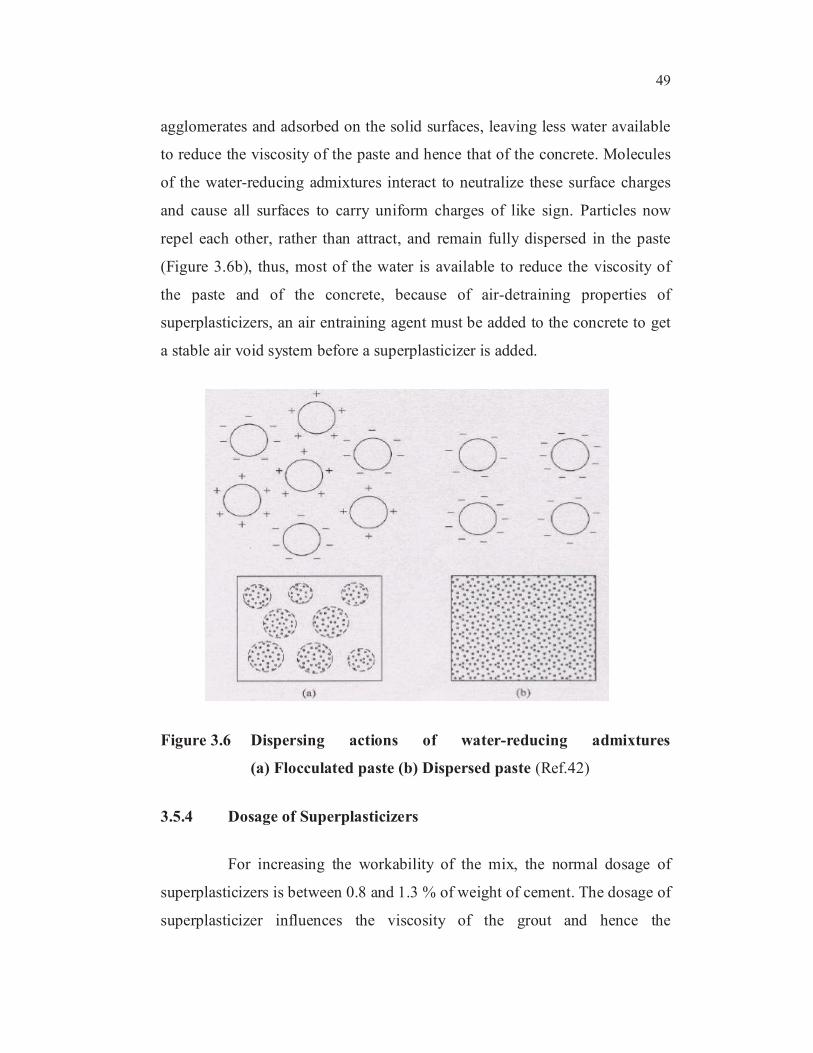
Water-reducing admixtures are negatively charged organic
molecules that adsorb primarily at the solid-water interface, whereas solid
particles carry residual charges on their surfaces, which may be positive,
negative or both. In cement paste, opposing charges on adjacent particles of
cement can exert considerable electrostatic attractions, causing the particles to
flocculate (Figure 3.6a). A considerable amount of water is tied up in these
49
agglomerates and adsorbed on the solid surfaces, leaving less water available
to reduce the viscosity of the paste and hence that of the concrete. Molecules
of the water-reducing admixtures interact to neutralize these surface charges
and cause all surfaces to carry uniform charges of like sign. Particles now
repel each other, rather than attract, and remain fully dispersed in the paste
(Figure 3.6b), thus, most of the water is available to reduce the viscosity of
the paste and of the concrete, because of air-detraining properties of
superplasticizers, an air entraining agent must be added to the concrete to get
a stable air void system before a superplasticizer is added.
Figure 3.6 Dispersing actions of water-reducing admixtures
(a) Flocculated paste (b) Dispersed paste (Ref.42)
3.5.4 Dosage of Superplasticizers
For increasing the workability of the mix, the normal dosage of
superplasticizers is between 0.8 and 1.3 % of weight of cement. The dosage of
superplasticizer influences the viscosity of the grout and hence the

50
workability of concrete. The effectiveness of a given dosage of a
superplasticizer depends on the water cement ratio of the mix. Specifically, at
a given dosage of the superplasticizer, the percentage water reduction which
maintains a constant workability is much higher at low water cement ratios
than at high water cement ratios.
3.5.5 Superplasticizers used in this Study
Three superplasticizers used in this study were,
SP1 - Polycarboxylic ether based superplasticizer
SP2 - Melamine sulphonated based superplasticizer
SP3 - Naphthalene sulphonated based superplasticizer
3.6 VISCOSITY-MODIFYING AGENT
3.6.1 General
Viscosity modifiers are high molecular-weight, water-soluble
polymers used to raise the viscosity of water. Such compounds increase the
cohesiveness of fresh concrete, reducing its tendency to segregate and bleed.
3.6.2 Effect of Viscosity-Modifying Agent
They work by attaching their long molecules to the water
molecules, process which inhibits the free displacement of water. These
agents are helpful in improving the properties of lean concretes with low
cement contents, concrete placed under water and concretes or grouts that are
placed by pumping. In the latter case, they reduce pumping pressures through
improved lubricating properties, as well as reducing segregation tendencies.
When compounds in this category are used to improve the cohesiveness of
concrete being placed underwater, they are classified as antiwashout

51
admixtures. Viscosity-modifying agents are added in concretes used in places
with extreme congestions due to reinforcement configurations or unusual
geometry forms, where fluid but cohesive concrete is required in order to
resist bleeding and segregation.
The materials commonly used are polyethylene oxides, cellulose
ethers, natural gums, and polyacrylamides or polyvinyl alcohol. Other
materials used are finely divided solids such as clays and lime, but they tend
to reduce the strength of the concrete and for these reasons they are primarily
used in grouts when strength is not of major importance.
3.6.3 VMA used in this Study
Three Viscosity Modifying Agent used in this study were,
VMA1 - Biopolymer
VMA2 - Carboxyl Methyl Cellulose
VMA3 - Organic aqueous solution
3.7 CONCRETE MIX DESIGN
3.7.1 General
The selection of suitable ingredients of concrete and the
determination of their relative proportions were done with an aim to produce
concrete of required strength and durability as economical as possible. Based
on the properties of cement, fine aggregate, coarse aggregate and water, the
mix proportion was calculated by adopting IS 10262 – 1982.
After determining material properties, mix for M25 and normal
concrete was designed and the mix for Self Compacting Concrete was fixed
by reducing coarser fractions and increasing finer fractions by the addition of

52
fly ash. Different admixtures in the form of HRWR and VMA were added to
the fly ash concrete to obtain Self Compacting Concrete and their properties
were studied in the fresh and hardened state.
3.7.2 Mix Design for Normal Concrete
Mix design for normal concrete was done by using Indian standard
method. Trial mixes were cast to obtain economical mix and details of final
mix arrived at are given below:
Design stipulation
i. Characteristic compressive strength - 25 N/mm².
ii. Maximum size of aggregate - 20 mm.
iii. Degree of workability - 0.9 C.F.
iv. Degree of quality control - Good
v. Type of exposure - Moderate
Design procedure
Target mean strength of concrete = 25+1.65×4
= 31.6 N/mm²
w/c for strength = 0.525
w/c for Durability = 0.5
w/c adopted = 0.5
Water content including surface water
per m³ of concrete = 186kg
53
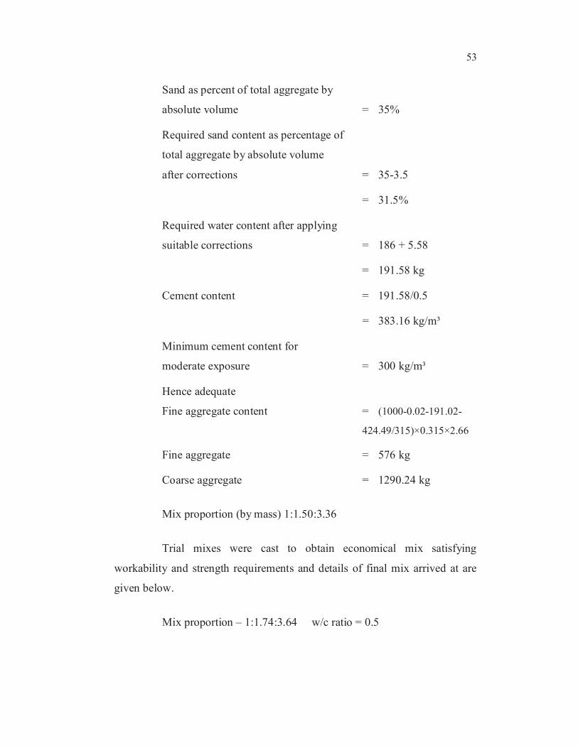
Sand as percent of total aggregate by
absolute volume = 35%
Required sand content as percentage of
total aggregate by absolute volume
after corrections = 35-3.5
= 31.5%
Required water content after applying
suitable corrections = 186 + 5.58
= 191.58 kg
Cement content = 191.58/0.5
= 383.16 kg/m³
Minimum cement content for
moderate exposure = 300 kg/m³
Hence adequate
Fine aggregate content = (1000-0.02-191.02-
424.49/315)×0.315×2.66
Fine aggregate = 576 kg
Coarse aggregate = 1290.24 kg
Mix proportion (by mass) 1:1.50:3.36
Trial mixes were cast to obtain economical mix satisfying
workability and strength requirements and details of final mix arrived at are
given below.
Mix proportion – 1:1.74:3.64 w/c ratio = 0.5

54
The material required for M25 grade normal concrete are presented
in Table 3.7
Table 3.7 Mix detail of M25 grade normal concrete
S.No. Materials Quantity (kg/m³)
1 Cement 350
2 Fly ash -
3 Fine aggregate 610
4 Coarse aggregate 1275
5 Water 175 lit.
6 Slump in mm 50
7 Compacting Factor 0.90
828 days compressive
strength in N/mm²34.940
3.8 MIX PROPORTION FOR SELF - COMPACTING
CONCRETE
3.8.1 General
Self - compacting concrete requires more powder content for more
flowability. Therefore the coarse aggregate content is reduced while
increasing the fine aggregate and fly ash is also added while keeping the
cement content same as that of normal concrete. Water content was adjusted
to suit the particular dosage of VMA and HRWR.
A detail of mix for 40% of fly ash by total binder was fixed and
materials required for 1 m3 of SCC are presented in Table 3.8.

55
Table 3.8 Materials required for one cubic metre of self - compacting
concrete
Materials Quantity(kg/m³)
Cement 350
Fly ash 234
Fine aggregate 875
Coarse aggregate 700
3.8.2 Mix Design for Self - Compacting Concrete
Concrete mix M25 having characteristic strength of 25 MPa was
examined. The mix proportioning was carried out by using the guidelines
given by EFNARC, in the absence of any codal recommendation, for
designing self compacting concrete.
Self - compacting concrete requires more powder content for more
flowability. The fines or the powder (all material less than 0.1mm) play a
decisive role for the proportioning of self compacting concrete. The powder
type of self - compacting concrete should have a reduced water-powder ratio.
This means that, the powder content should be more (cement+fillers+fines
from the aggregates) and is usually in the range of 500 to 600 kg/m³. Out of
this, the cement content can vary from 300 to 450 kg/m³ (as per BIS) and the
remaining is to be replaced by fly ash. Also the quantity of coarse aggregate is
reduced while fine aggregate is increased in self - compacting concrete. Trial
mixes were carried out with 25%, 30%, 35%, 40%, 45%, and 50%
replacement of cement by fly ash in the total powder to fix water to
cementitious material ratio (w/cm) by slump flow test. Cement content, for
each varying fly ash percentage, was obtained to suit replacement level and
the details of self - compacting concrete mix adopted is reported in Table 3.9.

56
Table 3.9 Materials required for one cubic metre of self - compacting
concrete
Sl.No Material FA25 FA30 FA35 FA40 FA45 FA50
1 Cement 438.00 408.80 379.60 350.40 321.20 292.00
2 Fly ash 146.00 175.20 204.40 233.60 262.80 292.00
3 Fine
Aggregate875.00 875.00 875.00 875.00 875.00 875.00
4 Coarse
aggregate700.00 700.00 700.00 700.00 700.00 700.00
3.9 FIXING WATER/CEMENTITIOUS MATERIAL RATIO
FOR SCC
A total of five different admixture combinations were tried with
different dosages. Slump flow test was carried out for each mix and the mix
which gave satisfactory flow value was chosen for the study on the properties
in fresh state and hardened state.
3.9.1 PCESP
Mixes PCESP1, PCESP2, PCESP3, PCESP4 and PCESP5 were
prepared by varying the dosage of PCE (HRWR) from 0.8 to 1.3% by weight
of cement.
3.9.2 Biopolymer
Mixes were prepared by varying the dosage of biopolymer for 0.35
and 0.40% by weight of total binder.

57
3.9.3 PCESP + Biopolymer
Varying the dosage of PCESP (HRWR) and Biopolymer (VMA)
different trial mixes as Table 3.10 were prepared and their performance was
studied.
3.9.4 MSSP + Carboxyl Methyl Cellulose
Varying the dosage of Carboxyl Methyl Cellulose (VMA) and
MSSP (HRWR) only two trials were carried out as given below.
3.9.5 NSSP + Organic Aqueous Solution
Varying the dosage of NSSP (HRWR) and Organic aqueous
solution (VMA) different trials were made as table presented in Table 3.10.
3.10 PROPERTIES OF SELF – COMPACTING CONCRETE
3.10.1 Fresh State
To determine the self - compactability of concrete, Slump flow test,
L-box test, U-box test and V-funnel test were conducted after fixing w/cm
ratio for each mix and the results are reported.
3.10.2 Hardened state
The mix which satisfied the properties in fresh state were chosen
for the determination of compressive strength in hardened state.
Three cubes of size 150×150×150 mm each were cast for the
determination of compressive strength at the age of 7 and 28 days for the
chosen mix and the results are reported in chapter 5.

58
Table 3.10 Mix proportions with various HRWR and VMA
ComponentsPCE
SP 1
PCE
SP 2
PCE
SP3
PCE
SP 4
PCE
SP 5BP1 BP2
PCESP+
BP3
PCESP+
BP4
PCESP+
BP5
MSSP
+CMC1
MSSP
+CMC2
NSSP
+AS1
NSSP
+AS2
Water
content in
litres
210 207 205 199 205 204 234 216 219 234 234 222 234 245
w/cm ratio 0.36 0.355 0.35 0.34 0.35 0.35 0.35 0.37 0.375 0.40 0.4 0.38 0.4 0.42
w/p ratio
(by volume)0.87 0.86 0.85 0.83 0.85 0.85 0.85 0.87 0.85 0.92 0.90 0.97 0.91 0.97
HRWR % by
wt of cement0.8 1.0 1.1 1.2 1.3 --- --- 1.0 0.9 0.8 1.25 1.5 0.65 0.75
HRWR in
litres2.8 3.5 3.85 4.2 4.55 --- --- 3.5 3.15 2.8 4.38 5.25 3.8 4.4
VMA % by
wt of total
powder
--- --- --- --- --- 0.35 0.40 0.1 0.15 0.2 1.0 1.1 0.75 0.5
VMA in
litres--- --- --- --- --- 2.04 2.34 0.58 0.88 1.17 3.5 3.85 4.4 2.9