Embed Size (px)
Citation preview

Battle Creek Salmon and Steelhead Restoration ProjectDraft Environmental Impact Statement/Environmental Impact Report
3-1July 2003
J&S 03-035
Chapter 3Project Alternatives
This chapter describes existing facilities at each project site within theRestoration Project area. Following the description of existing facilities, thischapter describes Restoration Project Alternatives.
Existing FacilitiesHydroelectric Project facilities and operations are discussed in Chapter 2. TheRestoration Project consists of the portion of the Hydroelectric Project below thenatural fish barriers, as shown in Figure 2-2. The upper project limit on NorthFork Battle Creek is the absolute natural fish barrier above North Battle CreekFeeder Diversion Dam, 14 miles upstream of the confluence. The upper projectlimit on South Fork Battle Creek is the natural fish barrier above South DiversionDam. The lower project limit is 9 miles upstream of the confluence of BattleCreek and the Sacramento River at a location just below the confluence ofColeman Powerhouse tailrace channel and the mainstem of Battle Creek. Thefollowing sections describe the nine project sites that are within the RestorationProject area. A description of a tenth site that is within the project area, theColeman Powerhouse site, is not included here because no modifications areproposed at the facility.
All powerhouses and diversion dams, except Soap Creek Feeder and LowerRipley Creek Feeder, have electrical power service. Electrical features will notbe described in detail. In general the powerhouse sites include switchyardswhich are connected to a network of overhead power transmission lines thattraverse between sites within and outside the Restoration Project area. Power isbrought to the diversion dam sites on overhead lines or along existing structuresand is used to operate mechanical features, such as sluice gates, to providelighting or to power various instrumentation used to monitor operating conditions(e.g. water level gauges).
PG&E either owns the land occupied by the project sites or has legal easement ofthe area. The project sites are located in remote areas. Generally, road access tothe project sites is over private property to which PG&E has legal easement. Forseveral sites, the last several hundred feet of access is by foot trail.
In the following descriptions the words left and right are used to indicate thedirection of a feature pertaining to a dam or canal while facing downstream. For

Battle Creek Salmon and Steelhead Restoration ProjectDraft Environmental Impact Statement/Environmental Impact Report
3-2July 2003
J&S 03-035
example, a canal intake that is on the right abutment means that it is on the rightside of the dam for a person looking in the downstream direction of flow.
North Battle Creek Feeder Diversion Dam(North Fork Battle Creek)
North Battle Creek Feeder Diversion Dam and Canal were constructed around1910 to divert 55 ft3/s of North Fork water into Cross Country Canal forgenerating power at South Powerhouse, located about 5 miles to the south. Thedam is a rock-filled masonry type, 8 feet in height, with an overall length ofapproximately 93 feet at crest elevation 2082.4. A 5-foot-wide hydraulic sluicegate is set near the middle of the dam to allow sluicing of sediments thatperiodically accumulate behind the dam. This prevents sediments from blockingthe canal headworks structure and fish ladder. Water is diverted through theconcrete headworks structure located on the left side of the dam through a 36-inch-wide-by-48-inch-high electrically controlled slide gate that transitions into ametal flume. The left side of the dam is approximately 3 feet higher than thecentral overflow section to provide protection to the headworks area from floodflows. The feeder “canal” is actually a steel flume (ARMCO #96), semi-circularin shape and about 5 feet in diameter. The flume is supported by steel trestlestructures as high as 11 feet above the original ground with concrete footingsanchored into bedrock. The flume extends approximately 700 feet downstreamof the dam where it discharges into an energy dissipation box, which alsoreceives water from the Volta 2 Powerhouse. Cross Country Canal begins at thispoint. Volta 2 Powerhouse is located approximately 150 feet directly across thecreek from the box. To the right of the sluice gate but still near the center of thedam is a metal Alaska Steeppass fish ladder, set inside an original concrete pooland weir fish ladder. The ladder structure is blocked to prevent upstream fishpassage at the request of DFG. The canal does not have any fish screeningsystem.
North Battle Creek FeederDiversion Dam and Canal

U.S. Department of the Interior, Bureau of Reclamation,State Water Resources Control Board
Project Alternatives
Battle Creek Salmon and Steelhead Restoration ProjectAdministrative Draft Environmental Impact Statement/Environmental Impact Report
3-3July 2003
J&S 03-035
North Battle Creek Feeder Diversion Dam is reached by driving north from thePG&E Manton Service Center on Wilson Hill Road, about 1 mile to a turnoff tothe Volta 1 and 2 Powerhouses. A private road consisting of paved and unpavedsections about 0.8 mile long leads to a sediment basin at the top of the plateauabove Volta 2 Powerhouse. A steep, paved section of access road incorporatesone switchback, then descends to a parking area at Volta 2 Powerhouse. Afootpath begins at Volta 2 Powerhouse and leads across a footbridge over NorthFork Battle Creek to the energy dissipation box. The dam is reached by walkingupstream along approximately 700 feet of walkway running down the centerlineof the flume. There is no vehicle access to the dam or feeder canal. PG&E ownsthe land on the northwest side of the creek. Flat areas at the top of the plateauabove the dam have been used to stage construction operations for performingvarious maintenance activities. There is no access from the opposite side of thecreek.
Eagle Canyon Diversion Dam(North Fork Battle Creek)
Eagle Canyon Diversion Dam and Canal were constructed in 1910 to divert up to70 ft3/s of North Fork water into Eagle Canyon Canal for generating power atInskip Powerhouse, located about 3 miles to the southwest. The dam is of rockmasonry construction, 15 feet in height, with an overall length of approximately70 feet at crest elevation 1430.2. A 4-foot-wide, 10-foot high manually operatedradial gate is set near the middle of the dam to allow sluicing of sediments thatperiodically accumulate behind the dam. A weir also stems off of the damupstream of the fish ladder and canal entrance area on the left abutment. Theradial sluice gate and weir help prevent sediments from blocking the fish ladderand canal entrance. The canal consists of an entrance channel about 7 feet widecontrolled by a 3.5-foot-wide-by-6-foot-high slide gate. The left wall of thechannel is the vertical rock of the right abutment. The right wall is of reinforcedconcrete and rock masonry construction. The handwheel for operating the radialgate is located along this wall about 75 feet from the radial gate. This wallsupports the left side of the Alaska Steeppass fish ladder, which is locatedbetween the canal entrance channel and the radial sluice gate. The canal channel
Eagle Canyon Diversion Dam

Battle Creek Salmon and Steelhead Restoration ProjectDraft Environmental Impact Statement/Environmental Impact Report
3-4July 2003
J&S 03-035
extends approximately 120 feet downstream of the dam before entering a 7-footwide-by-12-foot-high tunnel, which is Tunnel No. 1 of Eagle Canyon Canal. A3-foot-wide-by-6-foot high slide gate is located in the canal wall immediatelyupstream of the tunnel, which is used for sluicing and regulating diversion flows.A channel returns this discharged water back into the North Fork approximately150 feet downstream of the dam. The outlet portal of an abandoned 6-foot-wide-by-6-foot-high tunnel joins the canal channel approximately 25 feet downstreamof the dam. This tunnel was used during original construction to divert the creekto allow construction of the dam. Its inlet portal is located about 125 feetupstream of the dam. The tunnel is filled with water nearly to its crown and has aconcrete wall within the tunnel, which prevents the creek from flowing through.A significant amount of spring water cascades off of the left abutment wall atalmost all times of the year and is captured by the canal channel. An AlaskaSteeppass fish ladder, about 2 feet wide and extending about 40 feet downstreamof the dam, has been closed at the request of DFG. The canal does not have anyfish screening system.
The south canyon wall is a significant source of spring-fed water. The amount ofwater varies with the time of year with a maximum of around 10 ft3/s. PG&E hascollected this spring water with a system of troughs and pipes which convey thewater into Eagle Canyon Canal. These collection facilities extend approximately3000 feet downstream of the dam and about half way up the canyon wall.
Eagle Canyon Canal begins at Eagle Canyon Diversion Dam and extendsapproximately 2.6 miles to combine with flows from Inskip Canal immediatelyupstream of the penstock headworks for Inskip Powerhouse. The first 0.9 mile ofcanal is actually a series of tunnels and flumes that follow the south canyon rim.The tunnels are unlined and 7 feet wide by 8 feet high. The flumes are metalARMCO #108, supported by steel trestle structures founded on concrete footings.Beyond this point, the water is conveyed in an open channel for another 1.7 milesto the penstock headworks. Another approximately 8 ft3/s of spring water isintercepted by the canal over an approximate 2,000-foot stretch in the vicinity ofan area called Spring Gardens, located about 0.5 mile north of Manton Road.Most of the open channel sections of the canal are unlined. However, severalstretches of the 8-feet-wide-by-4-feet-deep channels have been lined with gunite(pneumatically applied concrete) in areas that are experiencing high leakage orare susceptible to erosion. A number of spillways are spaced along the canal atboth the tunnel/flume and open-channel sections. These spillways are eithergated or contain flashboards that are adjusted as required to ensure that the canaldoes not become overcharged with water. Occasionally, during periods ofintense rain runoff, the canal receives more water than it can contain. Thespillways provide a controlled means of releasing this water, which returns to theNorth Fork. The corridor along the canal is not fenced.
Eagle Canyon Diversion Dam is reached by driving southwest from the PG&EManton Service Center along Manton Road about 3 miles to a turnoff ontoprivate property. An unimproved road proceeds northerly about 1 mile to a smallparking area at the southern top of the plateau. A steep, 900-foot-long footpath,including stairs, descends approximately 160 feet and provides access to the damand diversion facilities. Three additional unimproved roads split off the main

U.S. Department of the Interior, Bureau of Reclamation,State Water Resources Control Board
Project Alternatives
Battle Creek Salmon and Steelhead Restoration ProjectAdministrative Draft Environmental Impact Statement/Environmental Impact Report
3-5July 2003
J&S 03-035
access road and lead to turnaround areas along the top of the plateau, where trailswith stairs are used to descend to points along the tunnels, flumes, and springcollection facilities of Eagle Canyon Canal. The northern top of the plateauabove the dam can be reached by driving north from the PG&E Manton ServiceCenter along Wilson Hill Road to Battle Creek Bottom Road. At about 1.5 milessouthwest of their junction an unimproved private road leads to aparking/turnaround area about 1 mile south of Battle Creek Bottom Road at thetop of the plateau. There is no vehicle or foot access to the site from the northplateau. However, the area has been used to stage construction operations forperforming various maintenance activities. Eagle Canyon Canal is reached off ofits intersection with Manton Road. To the north (upstream) of Manton Road thecanal banks are narrow and limited to foot or small vehicle access. To the southof Manton Road a 0.7-mile-long access road parallels the canal to its terminationat the Inskip Powerhouse penstock headworks.
Wildcat Diversion Dam(North Fork Battle Creek)
Wildcat Diversion Dam and Canal were constructed in 1912 to divert around20 ft3/s of North Fork water into Coleman Canal for generating power atColeman Powerhouse, located about 8 miles west of the dam. The dam is amasonry gravity structure 8 feet in height, with a 2-foot crest width, verticalupstream face and a downstream slope of about 0.5:1, and a 27-foot overflowcrest length at elevation 1074.7. The overall structure length is about 55 feetincluding the abutment sections. The upstream face has a concrete gunite facing.A gated sluiceway is set into the right side of the dam between the overflow crestand the headworks for the diversion pipe. The sluiceway is controlled by anupstream 24-inch-diameter slide gate, which is opened to allow sluicing ofsediments that periodically accumulate behind the dam. Water is divertedthrough a 30-inch-diameter steel pipe in the right abutment section. The steelpipe diversion includes a 6.5-foot-long upstream apron of masonry, a 4-foot-widesloping metal trashrack, and a 36-inch-diameter slide gate with a manuallyoperated pedestal lift and an intake sill. A 37.5-foot-long concrete steppool fishladder structure is located on the left abutment of the dam and contains an Alaska
Wildcat Diversion Dam and Pipeline

Battle Creek Salmon and Steelhead Restoration ProjectDraft Environmental Impact Statement/Environmental Impact Report
3-6July 2003
J&S 03-035
Steeppass fish ladder. The ladder is not blocked but has been determined to beinefficient and undersized. The diversion pipeline does not have any fishscreening system.
Wildcat Canal extends 1.9 miles from Wildcat Diversion Dam to its confluencewith Coleman Canal. The initial approximately 1.0 mile of the canal actuallyconsists of 24-inch-diameter welded steel pipe. The first 0.2 mile of pipe arelocated on the north side of the North Fork Battle Creek. At this point the pipecrosses the creek and continues the remaining 0.8 mile on the south side of thecreek. The entire length of pipe is aboveground and supported on variouspedestal arrangements. These include 240 concrete saddle supports (from 1 to 7feet high), 48 timber supports, and 20 steel pipe supports. The pipeline crossesthree watercourses (North Fork Battle Creek, Juniper Gulch, and ChickenHollow) before it terminates in a reinforced concrete transition structure. Theremaining 0.9 mile of Wildcat Canal consists of excavated channel sections thatare 5 feet wide and 2 feet deep, with occasional masonry or concrete lining, ashort corrugated-metal pipe culvert section beneath Wildcat Road, and a 600-footsection of natural channel. The excavated channel intercepts some concentrated,seasonal upslope drainage but there are no spillway structures as at WildcatCanal to prevent overcharging of the canal. Wildcat Canal finally discharges intoan open-channel section of Coleman Canal. No diversion of flow for powergeneration has occurred at the site since August 1995, under the terms of aninterim agreement with Reclamation. In August 1996, a rockfall damaged asection of the 24-inch-diameter pipe about 500 feet downstream of the dam.Pipeline repairs would be required to return Wildcat Canal to service. Generally,the corridor along the canal is not fenced by PG&E. Some fencing has beenerected by landowners at property lines, which are sometimes close to the canal.
Wildcat Diversion Dam is reached by driving north from the PG&E MantonService Center along Wilson Hill Road to Battle Creek Bottom Road. At about3.5 miles southwest of their junction, an unimproved private road leads to aparking/turnaround area about 1 mile south of Battle Creek Bottom Road at thetop of the plateau. There is no vehicle access to the site from the north plateau.A narrow, steep 500-foot-long path descends approximately 110 feet andprovides access to the dam and diversion facilities on the right abutment. Thereis no foot or vehicle access from the top of the left abutment down to the dam,even though PG&E owns the land. The overhead powerlines and poles that dropdown to the dam can be reached along an access road that turns off of MantonRoad about 1 mile east of Wildcat Road. The pipeline portions of Wildcat Canalon both the north and south sides of the creek have no vehicle access except atthe transition structure. The pipeline is reached by walking in from the diversiondam or the transition structure. Wildcat Canal is reached by driving west fromthe PG&E Manton Service Center along Manton Road about 6.5 miles to WildcatRoad. About 1 mile north of their junction, an unimproved private road parallelsthe canal to the east for about 0.5 mile and leads to a parking/turnaround areanear the transition structure. The section of canal to the west of Wildcat Roadhas no developed access road adjacent to the canal.

U.S. Department of the Interior, Bureau of Reclamation,State Water Resources Control Board
Project Alternatives
Battle Creek Salmon and Steelhead Restoration ProjectAdministrative Draft Environmental Impact Statement/Environmental Impact Report
3-7July 2003
J&S 03-035
South Diversion Dam(South Fork Battle Creek)
South Diversion Dam and Canal were constructed in 1910 to divert up to100 ft3/s of South Fork water into South Canal for generating power at SouthPowerhouse, located about 6 miles to the west. The structure has been rebuiltseveral times; the current structure has been in place since 1981. The dam is agravity structure of steel “bin-wall” construction with vertical upstream anddownstream faces 16 feet in height, with an overflow crest length of 100 feet anda crest width of 16.5 feet at elevation 2028.2. The left abutment non-overflowsection of the dam is 45 feet long and 7 feet above the overflow section, and theright abutment non-overflow section is 10 feet long and 5 feet above theoverflow section. The structure uses a system of adjoining closed-face binsgenerally 10 feet long, consisting of lightweight galvanized steel members boltedtogether and backfilled with gravel and cobbles obtained from the creek channel.The original reinforced concrete overflow crest is now covered with a ½-inch-thick welded-steel plate to provide protection against abrasion, which is severeduring flood flows. A 12-foot-wide-by-8-foot-high radial sluice gate is set nearthe right abutment within a reinforced concrete structure to allow the sluicing ofsediments that periodically accumulate behind the dam. The radial sluice gatehelps prevent sediments from blocking the canal entrance and fish ladder. TheSouth Canal intake structure is located to the right of the radial sluice gate andincludes a steel trashrack on a concrete sill, and a 60-inch-diameter slide gate atthe inlet portal of an unlined tunnel section (Tunnel No. 1). The trashracked exitof a denil type fish ladder is located to the left of the radial sluice gate. Theladder extends downstream 16 feet through the dam then turns left to follow anddescend along the downstream face of the bin wall an additional 51 feet. Theladder structure is attached to the bin wall. A metal roof covers the portion ofladder paralleling the bin wall to prevent water and debris that overflows the damfrom entering the ladder. The ladder is functional but does not meet currentstandards for fish ladder design. The canal does not have any fish screeningsystem.
The South Canal extends approximately 5.7 miles to its confluence with theCross Country Canal, where the canals combine to form the 3,555-foot-long
South Diversion Dam

Battle Creek Salmon and Steelhead Restoration ProjectDraft Environmental Impact Statement/Environmental Impact Report
3-8July 2003
J&S 03-035
Union Canal before entering the South Powerhouse penstock. The South Canalconsists of ten tunnel sections with a total length of 7,613 feet; nine metal flumesections with a total length of 2,384 feet; and 20,175 feet of excavated channelsections and concrete transitions. The tunnels are unlined and 8 feet wide by 8feet high. The metal flumes are ARMCO #132, supported by steel trestlestructures up to 37 feet high, founded on concrete footings. The excavatedchannel sections are 7 feet wide by 5 feet deep. Approximately 20 percent of thechannel sections are concrete lined. Runoff from upslope of the canal enters thecanal from natural drainages and from smaller disperse sources along the canal.Eleven spillways are spaced along the canal to prevent the canal from becomingovercharged. The spillways vary in their configuration. Some spillways areconcrete-capped low spots in the canal bank, sometimes with flashboards. Otherspillways are large, gated reinforced concrete structures involving diversion gatesin-line with the canal and through the canal bank. All of the spillways releasewater back to the South Fork. Soap Creek Diversion, which is a majorcontributor of side channel water to South Canal, is discussed below.
South Diversion Dam is reached by driving east from the PG&E Manton ServiceCenter about 4 miles along Forward Road to Ponderosa Way. At about 3 milessouth of their junction an unimproved private road continues south another2 miles to a parking/turnaround area adjacent to South Canal and 0.2 miledownstream of the dam. Road conditions vary seasonally but are generally steep,narrow, and in heavily rutted conditions, and require the use of four-wheel-drivevehicles. There is no vehicle access to the dam site. The dam is reached bywalking along the canal bank to the outlet of Tunnel No. 1. At this point, a steep,narrow trail rises above the tunnel and ends at the top of a 25-foot-tall ladder,which descends to the right abutment of the dam. The left abutment area couldbe reached by construction equipment and four-wheel-drive vehicles if anabandoned low-water crossing of the South Fork near the parking/turnaroundarea were reestablished. South Canal is reached over several private roads thatbranch off of Ponderosa Way and South Powerhouse Road. The first privateaccess road is the route described above, which branches off of Ponderosa Wayand provides access to the dam and the easterly most reaches of the canal. Asecond private access road branches off of Ponderosa Way near the Bluff Springsarea about 1.8 miles south of Forward Road. This road splits into two branchesthat provide access to the middle and western portions of South Canal. Thesoutherly branch extends 1.5 miles to the outlet of Tunnel No. 5 and to SoapCreek Diversion Dam. This road then continues westerly approximately 1.2miles along the canal (portions are well above the canal, other portions are alongthe canal bank) to the inlet of Tunnel No. 6 where it deadends. The westerlybranch travels along the plateau above the South Fork and several hundred feetnorth of South Canal. This westerly branch rejoins the South Canal 2.5 miles tothe west. An access point down to the area around the outlet of Tunnel No. 6begins about 1.3 miles west of the Bluff Springs branch and heads south about0.4 mile where it dead ends. Vehicle access does not exist between the outlet ofTunnel No. 6 and 600 feet downstream of the outlet of Tunnel No. 9. Theremaining 1.2-mile stretch of the westerly branch that joins the private SouthPowerhouse Access Road is along the South Canal bank. Continuing along thecanal alignment (actually above Tunnel No. 10) to the west of the private SouthPowerhouse Access Road, an access road extends 0.1 mile to the outlet of Tunnel

U.S. Department of the Interior, Bureau of Reclamation,State Water Resources Control Board
Project Alternatives
Battle Creek Salmon and Steelhead Restoration ProjectAdministrative Draft Environmental Impact Statement/Environmental Impact Report
3-9July 2003
J&S 03-035
No. 10 and the South Canal junction with Union Canal. The third private accessroad is named the South Powerhouse Access Road. It extends south from theintersection of South Powerhouse Road and Hazen Road, approximately 0.9mile, and provides access to the westerly portions of South Canal. The SouthPowerhouse Access Road is described in more detail below for the SouthPowerhouse site. The corridor along the canal banks is not fenced. The corridoralong the main access road branches is usually fenced and contains several gatesalong its route.
Soap Creek Feeder Diversion Dam(Soap Creek, Tributary to South Fork Battle Creek)
Soap Creek Feeder Diversion Dam and Pipeline were constructed in the 1900s todivert up to 15 cfs of water from Soap Creek into South Canal for generatingpower at South Powerhouse located about 4 miles to the west. The dam waspossibly replaced in 1936. The dam is located on Soap Creek about 4 milessoutheast of Manton, California, and about 1 mile upstream of its confluencewith the South Fork of Battle Creek. The dam consists of a concrete gravitystructure 10 feet in height, with an overall length of 41 feet at a maximum crestelevation 2,025.2. A 20-foot-long overflow section is provided in the middleportion of the dam at elevation 2,023.1. A 42-inch-square slide gate is set nearthe left abutment to allow sluicing of sediments that periodically accumulatebehind the dam that might block the entrance to the pipeline. Water is divertedthrough a 24-inch-diameter hydraulically operated slide gate into a 24-inch-diameter steel pipe in the right abutment section. The pipeline extends along theright canyon wall approximately 300 feet before discharging into the South Canalflume located immediately downstream of the Tunnel No. 5 outlet. The entirelength of pipe is aboveground and supported on various concrete saddle supportsup to 4 feet high. The junction box at the discharge point includes a stilling well,venturi flume and a 27-foot-long No. 72 metal flume. There are no fish passagefacilities at this site.
Soap Creek Diversion Dam is reached as described above for South Canal alongthe southerly branch of access road from Bluff Springs. The access road ends at
Soap Creek Feeder Diversion Dam

Battle Creek Salmon and Steelhead Restoration ProjectDraft Environmental Impact Statement/Environmental Impact Report
3-10July 2003
J&S 03-035
a parking/turnaround area about 50 feet above the dam. A 200-foot-long, narrowtrail and stairs descend to the right abutment of the dam. There is no access trailalong the pipeline. There is an access road about 50 feet above and parallelingthe pipeline. A rough trail, often wet from springs, leads down from the road tothe stilling well area and Flume 3, which are about 100 feet downstream of theoutlet of Tunnel No. 5. The corridor along the pipeline is not fenced.
Inskip Diversion Dam/South Powerhouse(South Fork Battle Creek)
Inskip Diversion Dam, South Powerhouse, and Inskip Canal were originallyconstructed in 1910. South Powerhouse generates power from water delivered tothe penstock from the North and South Forks of Battle Creek. South Powerhouseis located on the north bank of the South Fork of Battle Creek approximately1,100 feet upstream of Inskip Diversion Dam. The powerhouse receives up toabout 190 cfs of water at 515 feet of head via an approximately 1,750-foot-longsteel penstock from Union Canal. Union Canal receives water from the upperportion of South Fork Battle Creek via South Canal and from the upper portion ofNorth Fork Battle Creek via the Cross Country Canal. After passing through theturbines or Howell-Bunger bypass valve, powerhouse flows are released backinto the South Fork through the tailrace. The tailrace contains a 40-foot-long, 10-foot-wide, reinforced concrete structure with vertical walls. Discharged watercontinues downstream in a tailrace channel that extends downstream about 600feet, where it discharges into the South Fork Battle Creek. Water released intoSouth Fork Battle Creek at this point is a mixture of South Fork and North ForkBattle Creek waters. A peninsula area is formed between the tailrace channel andthe South Fork creek channel that extends about 450 feet downstream of SouthPowerhouse. The elevation of the peninsula is somewhat lower than adjacentground and has been overtopped and breached during flood events over the years.PG&E last rebuilt the peninsula after the 1997 floods.
At the top of the penstock is a forebay with a sediment basin and an overflowspillway. The spillway serves as a bypass for the penstock whenever water flowthrough the powerhouse is stopped or when Union Canal water deliveries exceed
Inskip Diversion Dam

U.S. Department of the Interior, Bureau of Reclamation,State Water Resources Control Board
Project Alternatives
Battle Creek Salmon and Steelhead Restoration ProjectAdministrative Draft Environmental Impact Statement/Environmental Impact Report
3-11July 2003
J&S 03-035
penstock/powerhouse capacity. Overflow situations can occur when thepowerhouse experiences a sudden unscheduled shutdown, during a scheduledpowerhouse shutdown but deliveries are still required from the North Fork intothe South Fork system (i.e., to Inskip Canal), during minor operational flowmismatches between the canal deliveries and the powerhouse, and duringovercharging of the canal system because of high precipitation events. Bypassedwater is released to an open gully that flows down the hillside to the powerhousetailrace channel and South Fork Battle Creek.
Inskip Diversion Dam diverts approximately 220 ft3/s of water from the SouthFork Battle Creek (a mixture of North and South Fork water) to Inskip Canal,which conveys the water to the Inskip Powerhouse located approximately 5.4miles downstream. Inskip Diversion Dam is a rock-filled masonry structure28 feet in height with a steel-capped dam crest approximately 80 feet long atcrest elevation 1,439. A 6-foot-wide, 17-foot-high radial sluice gate is set nearthe right abutment to allow the sluicing of sediments that periodically accumulatebehind the dam. The radial sluice gate helps prevent sediments from blockingthe adjacent canal entrance. The Inskip Canal intake structure diverts water onthe north side of the dam through an 11-foot-wide radial gate. Diverted waterpasses through a 100-foot-long, 8-foot-wide-by-8-foot-high, unlined TunnelNo. 1 and a sediment trap before entering Inskip Canal. The sediment trap is a6-foot-deep basin between the tunnel outlet and the canal, which capturessediment before it can enter the canal system. The basin incorporates a sidechannel radial sluice gate that is 6 feet wide and 15 feet high. The gate isperiodically opened to sluice sediments out of the basin and into the South Forkat a point about 200 feet downstream of the dam. Inskip Canal extends 650 feetdownstream of the sediment basin before entering Tunnel No. 2. The canal is anopen channel approximately 8 feet wide and 6 feet deep and is unlined for mostof its length. Portions have been lined with gunite in areas of high leakage orsevere erosion. The portions of Inskip Canal further downstream are notdescribed because there are no proposed modifications until the header box areaabove Inskip Powerhouse. Near the left side of the dam is an Alaska Steeppassfish ladder set within the walls of the original concrete pool and weir ladder. Thecanal does not have any fish screening system.
The Inskip Diversion Dam/South Powerhouse site is reached by driving southfrom the PG&E Manton Service Center along Manton Road, then south for1.2 miles on South Powerhouse Road. From this intersection of SouthPowerhouse Road and Hazen Road a private, dirt and graveled road proceedssouth another mile to the top of the canyon. A portion of this stretch passes closeto a residence, and the speed limit is restricted. From the top of the canyon asteep, narrow, winding, paved road continues down the hillside for about anothermile to a parking area at the South Powerhouse. This section of private roadfrom Hazen Road to South Powerhouse is called the South Powerhouse AccessRoad. Access to the right (north) side of the dam is by a 1,400-foot-long foottrail above the South Fork Battle Creek. The left (south) side of the dam can beaccessed by four-wheel-drive vehicle over a concrete, low-water crossing of thecreek adjacent to the powerhouse. A private dirt road parallels the creek forabout 1,000 feet and terminates at the dam. There is no vehicle access across the

U.S. Department of the Interior, Bureau of Reclamation,State Water Resources Control Board
Project Alternatives
Battle Creek Salmon and Steelhead Restoration ProjectAdministrative Draft Environmental Impact Statement/Environmental Impact Report
3-12July 2003
J&S 03-035
creek at the dam site. Personnel can cross the dam crest on foot if the waterlevels are low enough.
An abandoned access road is located about 2,000 feet east of the residence. Thisroad extends from the intersection of Hazen Road and Manton School Road in asoutherly direction about 0.8 mile and reconnects with the South PowerhouseAccess Road south of the residence. This road will require upgrading to allowconstruction equipment to safely bypass the residential area.
Lower Ripley Creek Feeder Diversion Dam(Ripley Creek, Tributary to South Fork Battle Creek)
Lower Ripley Creek Diversion Dam is located on Ripley Creek about 3.5 milessouthwest of Manton, California, and about 1 mile upstream of its confluencewith South Fork Battle Creek. The diversion dam provides up to 3 cfs to InskipCanal, from an open canal, for power generation at Inskip Powerhouse (nearColeman Diversion Dam). The existing dam was constructed in 1944, replacingan older concrete structure constructed in 1929, which in turn had replaced theoriginal wooden structure constructed before 1918. A concrete measuring weirwas added to the diversion canal in 1952. The existing dam consists of a17-inch-thick concrete wall with a maximum structural height of about 5 feet anda crest length of 44 feet at elevation 1,404.4. An 8-foot-wide overflow sectionwith wooden flashboards is provided for releases to Ripley Creek. Diversionreleases are made through a 22-by-35-inch wooden slide gate near the leftabutment (invert elevation 1,401.5). The feeder canal extends 384 feetdownstream from the dam and discharges into a short open-channel section ofInskip Canal between the outlet of a tunnel and the inlet of a flume. Immediatelyadjacent to the feeder canal outlet is a reinforced concrete uncontrolled overflowweir spillway that discharges excess Inskip Canal water back into Ripley Creek.There are no fish passage facilities at this site.
The Lower Ripley Creek site is reached by driving southwest from the PG&EManton Service Center about 4.5 miles along Manton Road to the Eagle CanyonCanal crossing. The access road parallels the canal for about 0.6 mile to theInskip Powerhouse penstock headworks area. A dirt access road then turnseasterly and proceeds 1.7 miles to the site. The Lower Ripley worksite can alsobe reached from the South Powerhouse Access Road. From the top of thecanyon an unimproved road on private property can be taken in a westerlydirection about 3 miles to the worksite. For both routes, road conditions varyseasonally, but are generally flat, narrow, in heavily rutted condition and requirethe use of four-wheel-drive vehicles. The dam is about 50 feet off of the roadand can be easily reached by foot and construction equipment. The corridorsalong the access roads, dam and feeder canal are not fenced but there are a fewgates along the routes. There is a bridge of unknown load-carrying capacity thatcrosses Union Canal for the road that approaches from the east.

U.S. Department of the Interior, Bureau of Reclamation,State Water Resources Control Board
Project Alternatives
Battle Creek Salmon and Steelhead Restoration ProjectAdministrative Draft Environmental Impact Statement/Environmental Impact Report
3-13July 2003
J&S 03-035
Coleman Diversion Dam/Inskip Powerhouse(South Fork Battle Creek)
Coleman Diversion Dam, Inskip Powerhouse and Coleman Canal were originallyconstructed around 1912. Inskip Powerhouse generates power from waterdelivered to the penstock from the North and South Forks of Battle Creek. InskipPowerhouse is located on the north bank of the South Fork of Battle Creekapproximately 900 feet upstream of Coleman Diversion Dam. The powerhousereceives up to about 293 ft3/s of water at 378 feet of head via an approximately3,200-foot-long, 72-inch-diameter steel penstock. The penstock receivescombined North and South Fork water from Inskip Canal and North Fork waterfrom Eagle Canyon Canal at an inlet upstream of the penstock header box. Theheader box is of masonry construction approximately 40 feet square by 15 feettall, incorporating trashracks and a small basin with a sloping floor to capturesediments. Valves in the header box wall allow sand and grit to be flushedperiodically. This discharged water flows northwestward initially down a seriesof shallow braided channels that eventually combine into a single channel calledChicken Hollow. This flow continues for about 2 miles, crossing under MantonRoad and finally entering the North Fork of Battle Creek. The initial 2,200 feetof penstock crosses the somewhat flat upland, while the final 1,000 feet descendsthe valley hillside down to the powerhouse. Near this change in slope, thepenstock crosses a 24-inch-diameter corrugated metal pipe culvert that supplieswater to a trout hatchery located on the north side of Manton Road. The sourceof this water is the area called Willow Springs, which is located about 1,000 feeteast of the penstock. After passing through the turbines or Howell-Bungerbypass valve, powerhouse flows are released back into the South Fork throughthe tailrace outlet, which consists of a 31-foot-long, 12-foot-wide, curvedconcrete structure with vertical walls. The structure floor slopes upward from theturbine draft tube sump to the Battle Creek streambed. Water released into SouthFork Battle Creek at this point is a mixture of South Fork and North Fork BattleCreek waters.
Coleman Diversion Dam andInskip Powerhouse

Battle Creek Salmon and Steelhead Restoration ProjectDraft Environmental Impact Statement/Environmental Impact Report
3-14July 2003
J&S 03-035
An uncontrolled overflow wasteway is located on Inskip Canal about 500 feetupstream from the headerbox inlet. The overflow wasteway serves as a bypassfor the penstock whenever water flow through the powerhouse is stopped orwhen Eagle Canyon and Inskip Canal water deliveries exceedpenstock/powerhouse capacity. Overflow situations can occur when thepowerhouse experiences a sudden unscheduled shutdown, during a scheduledpowerhouse shutdown but deliveries are still required from the North Fork intothe South Fork system (i.e., to Coleman Canal), during minor operational flowmismatches between the canal deliveries and the powerhouse, and duringovercharging of the canal system because of high precipitation events.
Bypassed water flows over a gunite-lined low spot in the canal bank that is about50 feet wide and 30 feet long. This water is released to an unlined, 0.5-mile-longchannel excavated through the plateau area. At the end of this channel the watercascades off of the canyon hillside east of Inskip Powerhouse and enters theSouth Fork. The wasteway has an estimated capacity of 340 ft3/s.
Coleman Diversion Dam diverts up to 340 ft3/s from the South Fork of BattleCreek (a mixture of North and South Fork water) to Coleman Canal, whichconveys the water to the Coleman Powerhouse located about 10 miles to thewest. The dam is a masonry gravity structure with a concrete overlay, 12 feet inheight, with a crest length of 87.5 feet at elevation 1006.1. The dam structure hasa near-vertical upstream face, and a sloping downstream face and apron thatprovide a maximum base width of about 19 feet. A 14-foot-wide-by-8-foot-highradial sluice gate, located at the right end of the dam, is raised by a hand-operateddrum winch on a hoist deck directly above the gate. The gate is opened to allowsluicing of sediments that periodically accumulate behind the dam. A weir wall(described below) also stems off of the dam to the right of the fish ladder andextends upstream of the canal entrance. The radial sluice gate and weir helpprevent sediments from blocking the fish ladder and canal entrance. The fishladder located between the radial sluice gate and the canal entrance is an AlaskaSteeppass ladder, with a design capacity of 7 to 10 cfs and a total length of about54 feet, including two baffled steel flume sections and a 7-foot-long concrete turnbox. A 24-inch-wide slide gate controls releases to the fish ladder. The ladderhas been closed at the request of DFG.
Diversions into Coleman Canal are controlled by a set of gate structures locatedwithin the canal 200 feet downstream of the dam. A masonry gravity weirstructure extends upstream from the dam on the right abutment to serve as theintake to Coleman Canal. The intake weir structure has a crest width of about4 feet, a crest length of 44 feet and rises about 12 feet above the originalstreambed surface, with near vertical upstream and downstream faces. Betweenthe canal control gates and the intake weir, a 2-foot top width, 200-foot-longmasonry gravity retaining wall forms the left bank of Coleman Canal. Theelevation of the top of the wall is only slightly higher (0.2 feet) than the overflowsection of the dam. It is common during the higher flow times of the year forwater to spill over the wall in addition to the dam crest. During flood events, asignificant amount of water spills over the wall. Water spilled over this wallreturns to the South Fork and is a mixture of North and South Fork water andmay reduce the effectiveness of the fish ladder. A second masonry wall forms

U.S. Department of the Interior, Bureau of Reclamation,State Water Resources Control Board
Project Alternatives
Battle Creek Salmon and Steelhead Restoration ProjectAdministrative Draft Environmental Impact Statement/Environmental Impact Report
3-15July 2003
J&S 03-035
the right bank of the canal adjacent to the dam and curves upstream for 34 feet.Coleman Canal extends nearly 10 miles to the Coleman Forebay andPowerhouse, and consists of 389 feet of rock tunnel sections; 83 feet of concretebench flume; 46,240 feet of excavated channel sections; and 4,518 feet of 90-inch-diameter siphon pipe. The canal does not have any fish screening system.
The Coleman Diversion Dam/Inskip Powerhouse site is reached by driving westfrom the PG&E Manton Service Center along Manton Road for 6 miles (about0.5 mile east of the intersection of Manton Road and Wildcat Road). A private,paved road descends in an easterly direction about 0.4 miles to the dam andpowerhouse area. This relatively large and flat area was the site of the originalconstruction camp and powerhouse operator residences. There is vehicle accessto dam and powerhouse. However, there is no vehicle access from this areaadjacent to the creek up the steep hillside to the penstock header box area. Thepenstock header box area is reached from an access road at the intersection ofManton Road and Eagle Canyon Canal about 1.7 miles east of thedam/powerhouse access road. This dirt and gravel road parallels the canal forabout 0.6 mile to the Inskip Powerhouse penstock headworks area. The canaloverflow wasteway is reached by crossing a bridge over Eagle Canyon Canal andanother bridge that crosses the inlet forebay immediately upstream of the headerbox. A primitive road continues east 500 feet to the north bank of the wastewaychannel about 100 feet from the gunite-lined overflow structure, which cannot bereached by vehicle. There is an unimproved access road along the south side ofthe penstock that extends to the edge of the plateau. From the end of this roadthe Willow Springs pipeline intake area can be reached by foot. The majority ofthis 1-mile-long pipeline can only be reached by foot. Between Manton Roadand the penstock is a rough road that follows the pipeline for a few hundred feet.This road begins off of Manton Road about 0.2 mile east of the dam/powerhouseaccess road.
Asbury Pump Diversion Dam(Mainstem Battle Creek)
Asbury Pump Diversion Dam is located on Baldwin Creek, just below the DarrahSprings State Fish Hatchery and approximately 0.7 mile above its confluencewith Battle Creek. The dam was constructed around 1920. Baldwin Creek hasbeen identified as one of seven tributaries to Battle Creek capable of providingsuitable habitat for steelhead. The Darrah Springs facility is a key hatchery ofthe DFG inland fisheries program and raises catchable trout for sport fisheries.Asbury Pump Diversion Dam is a concrete gravity structure with a maximumheight of approximately 7 feet above streambed and a crest length of 100 feet.Two spill gates are provided near the middle of the structure with widths of 6 and10 feet. An access walkway crosses above the spill gates and allows foot accessto both sides of the facility. The Asbury Pump Station is located near the rightabutment of the dam and provides a 24-inch centrifugal pump with a ratedcapacity of 20,000 gal/min (45 cfs). Pump station flows pass over an 8-foot-longintake sill and enter a 26-inch-diameter intake pipe to the electric-motor–operated

U.S. Department of the Interior, Bureau of Reclamation,State Water Resources Control Board
Project Alternatives
Battle Creek Salmon and Steelhead Restoration ProjectAdministrative Draft Environmental Impact Statement/Environmental Impact Report
3-16July 2003
J&S 03-035
pump. The pumped releases enter the 36-inch-diameter Asbury pipe, whichextends 1,609 feet to the Coleman Canal siphon. The pipeline crosses BaldwinCreek just downstream of the diversion dam from the pump station on the rightabutment to the left bank. The pipeline is supported on reinforced concrete piers.A 36-inch-diameter steel surge pipe is also provided for surge protection. Thereare no fish passage facilities at this site.
The Asbury Pump Diversion Dam site is reached by driving west from the PG&EManton Service Center along Manton Road for 6.5 miles to Wildcat Road thenproceeding north about 2 miles to the turnoff for the Darrah Springs facility. Anunimproved road heads in a westerly direction about 1.4 miles past the hatcheryfacility to the dam and pump station area which provides vehicle access to theleft side of the facility. Foot access to the right abutment area is possible over thewalkway. Vehicle access to the right abutment and pump station area is off ofWildcat Road about 1.3 miles north of the Darrah Springs turnoff. Anunimproved road then proceeds 1.7 miles west and south to the pump station.
Project Alternatives DescriptionsThe project alternatives are described below in detail, beginning with the NoAction Alternative and followed by four Action Alternatives that propose variouscombinations of water management strategies for achieving the purpose of andneed for the Restoration Project. The purpose and need for the RestorationProject are described in Chapter 2.
Each alternative is described with respect to its Hydroelectric Project facilitymodifications. Each alternative description includes a map showing the northand south forks of Battle Creek and the facility modifications that would resultfrom the implementation of that particular alternative. Each map also includes aninset table, the rows of which correspond to different Battle Creek HydroelectricProject dams and diversions on the map. The values in the table are theminimum instream flow releases that would be maintained downstream of eachof the corresponding dams and diversions if that particular alternative were to beimplemented and the identified facility modifications completed.
The Action Alternatives were developed through a collaborative effort amongagencies, stakeholders, interested parties, and the public. The decision-makersused the following information to develop Action Alternatives to meet thepurpose of and need for the Restoration Project:
flow- and temperature-monitoring data,
screen and ladder criteria, and
hydropower operations data.
Additional information was obtained from existing programs and plans:

U.S. Department of the Interior, Bureau of Reclamation,State Water Resources Control Board
Project Alternatives
Battle Creek Salmon and Steelhead Restoration ProjectAdministrative Draft Environmental Impact Statement/Environmental Impact Report
3-17July 2003
J&S 03-035
CVPIA (Title 34 of Public Law 102-75, 1992) AFRP;
CALFED California Bay-Delta Ecosystem Restoration Program;
Upper Sacramento River Fisheries and Riparian Habitat Management Plan(California Senate Bill 1086, 1989);
Proposed Recovery Plan for Sacramento River Winter-Run Chinook Salmon,prepared by NOAA Fisheries (1997b); and
Actions to Restore Central Valley Spring-Run Chinook Salmon, prepared byDFG (pers. comm. 1996).
Each of the Action Alternatives1 is named for the number of dams that itproposes to remove. The Action Alternatives are the:
Five Dam Removal Alternative—Proposed Action
No Dam Removal Alternative
Six Dam Removal Alternative
Three Dam Removal Alternative
These names were chosen because they can easily be differentiated, and theyfocus on one water management strategy—dam removal2—that is easy toremember and has the greatest public awareness and familiarity associated withfish restoration. However, it is important to note that the names used for thealternatives refer to only one of many water management strategies included ineach Action Alternative. Other water management strategies may includemaintaining the dam, installing a fish ladder, and increasing the amount of waterreleased from the dam diversion and selected springs.
A No Action Alternative, as required by NEPA, is also analyzed and discussed inthis chapter. A sixth alternative that was considered, but eliminated from furtherstudy, is discussed at the end of this chapter.
1 These names were developed during the preparation of this document. During the public scoping process, thealternatives were referred to by number. The numbered alternatives are referred to in this EIS/EIR as follows:Public Scoping Alternative 1 is now called the No Action Alternative; Public Scoping Alternative 2 is now calledthe No Dam Removal Alternative; Public Scoping Alternative 3 is now called the Five Dam Removal Alternative(the Proposed Action); Public Scoping Alternative 4 is now called the Six Dam Removal Alternative; and PublicScoping Alternative 5 is now called the Three Dam Removal Alternative.
2 Other documents relevant to the Restoration Project use the word decommissioning when discussing dam removalson Battle Creek. FERC considers the decommissioning of a hydroelectric project to cover a broad range ofactivities, from simply locking the powerhouse door and securing the specific hydroelectric project, to complete damremoval and securing all appurtenant conveyance systems and facilities. According to FERC, decommissioning ahydroelectric project can mean lowering a dam or breaching a portion of a dam but not entirely removing the dam.For the purposes of this document, the term removal is used when referring to dam decommissioning for the ActionAlternatives.

U.S. Department of the Interior, Bureau of Reclamation,State Water Resources Control Board
Project Alternatives
Battle Creek Salmon and Steelhead Restoration ProjectAdministrative Draft Environmental Impact Statement/Environmental Impact Report
3-18July 2003
J&S 03-035
Some of the Action Alternatives involve abandoning project sites. At theselocations, the legal easements will need to be modified or retired and theassociated responsibilities shifted from PG&E to the landowner. The details ofthe conditions have not been finalized and are only described to the level of detailknown at this time. Other alternatives involve acquiring additional permanenteasements. All Action Alternatives involve the need for temporary easements.The acquisition of these easements is in preparation, and they are described onlyto the level of detail known at this time.
No Action AlternativeThe No Action Alternative is required by NEPA (42 USC 4321–4347). The NoAction Alternative is also known as the No Project Alternative under CEQA.The No Action Alternative represents conditions under a “no salmon or steelheadrestoration project” or “future without salmon and steelhead restoration project”alternative. The No Action Alternative is defined by the existing FERC licenseconditions for the Hydroelectric Project and other existing environmental andresource conditions. Instream flow releases under the No Action Alternative arethe license-required continuous minimum flows of 3 cfs below dams in NorthFork Battle Creek and 5 cfs below dams in South Fork Battle Creek. Existingfish ladders would be operated according to the conditions set forth in theHydroelectric Project’s FERC license. Fish screening of the existing diversioncanals is assumed not to be included in the No Action Alternative. PG&E wouldcontinue to maintain license-required stream gages, documentation, andoperations criteria consistent with the license requirements. PG&E also wouldcontinue to be responsible for all costs associated with this alternative.Figure 3-1 displays the facilities and flows that would occur under the No ActionAlternative.
Since 1995, Reclamation has maintained interim flow agreements3 with PG&E tomaintain higher minimum instream flows until a long-term restoration projectcan be implemented on Battle Creek. Terms of these agreements includeincreasing instream releases at Eagle Canyon and Coleman Diversion Dams at upto 30 cfs, suspending diversions at Wildcat Diversion Dam, and blockingdownstream entrances to the fish passage facilities at Eagle Canyon and ColemanDiversions Dams. A major portion of the increased release at the Eagle Canyonsite would be accomplished by bypassing the Eagle Canyon Springs collectionfacilities that discharge to the Eagle Canyon Canal. The interim flow agreementsrepresent a short-term set of resource conditions that are not guaranteed tocontinue and are not conditions of the existing FERC license. Therefore,resource conditions established under the interim flow agreements are notincluded as part of the No Action Alternative. The resource conditions include
3 The interim agreements between PG&E and Reclamation are discussed in greater detail in Chapter 6, “RelatedProjects.”

U.S. Department of the Interior, Bureau of Reclamation,State Water Resources Control Board
Project Alternatives
Battle Creek Salmon and Steelhead Restoration ProjectAdministrative Draft Environmental Impact Statement/Environmental Impact Report
3-19July 2003
J&S 03-035
reopening fish ladders now closed at Eagle Canyon and Coleman DiversionDams under the interim agreement conditions. Wildcat Canal would berewatered to convey water from North Fork Battle Creek to Coleman Canal, andminimum instream flow releases from the diversion dams would be returned toFERC license conditions.
Five Dam Removal Alternative—Proposed ActionThe Five Dam Removal is the Proposed Action that modifies both facilities andoperations to provide the water management consistent with the descriptions inthe MOU (Appendix A). Table 3-1 lists the individual components of the FiveDam Removal Alternative. Figure 3-2 displays the facilities and flows thatwould occur under this alternative. The inset table in Figure 3-2 indicates thecontinuous minimum instream flow releases that would increase below NorthBattle Creek Feeder, Eagle, Inskip, and Asbury Diversion Dams after completionof facility modifications.
The instream flows are an integral component of the Five Dam Removal Project.The Battle Creek Working Group (BCWG) Biological Technical Teamcollaboratively developed a detailed minimum flow release schedule for eachdam. The Technical Team included biologists from government fisheryagencies, PG&E, and participants from the BCWG. The proposed flow scheduleprioritized species by stream reach and considered flows providing passage andwater temperature. One outside review was completed as a comparison to recentlyapplied methodology at another Central Valley Salmon stream. During thedevelopment of the Battle Creek Salmon and Steelhead Restoration Project MOUthe flow schedule developed by the Biological Team was reviewed and acceptedalong with an adaptive management plan that would address future uncertainties.
Table 3-1. Five Dam Removal Alternative Components
Site Name Component
North Battle Creek Feeder Diversion Dam 55-cfs fish screenFish ladder
Eagle Canyon Diversion Dam 70-cfs fish screen
Fish ladder
Wildcat Diversion Dam Dam and appurtenant facilities removed
South Diversion Dam Dam and appurtenant facilities removed
Soap Creek Feeder Diversion Dam Dam and appurtenant facilities removed
Inskip Diversion Dam and South Powerhouse 220-cfs fish screen
Fish ladder
Construction of South Powerhouse andInskip Canal connector (tunnel)
U.S. Department of the Interior, Bureau of Reclamation,State Water Resources Control Board
Project Alternatives
Battle Creek Salmon and Steelhead Restoration ProjectAdministrative Draft Environmental Impact Statement/Environmental Impact Report
3-20July 2003
J&S 03-035
Site Name Component
Lower Ripley Creek Feeder Diversion Dam Dam and appurtenant facilities removed
Coleman Diversion Dam and Inskip Powerhouse Dam removed
Construction of Inskip Powerhouse and Coleman Canal connector
Inskip Powerhouse bypass replaced
Asbury Diversion Dam Reoperate
Stream gaging station installed
Minimum instream flow set for Baldwin Creek
The following sections describe the proposed activities under the Five DamRemoval Alternative for North Battle Creek Feeder, Eagle Canyon, Wildcat,South, Inskip, Coleman, Lower Ripley Creek, and Soap Creek Feeder DiversionDam sites.
Construction under the Five Dam Removal Alternative is anticipated to begin inearly 2004 and end by fall 2006. The construction schedule for each project siteis as follows:
North Battle Creek Feeder Diversion Dam—Begin construction in spring2005 and end by summer 2006.
Eagle Canyon Diversion Dam—Begin construction in spring 2005 and endby summer 2006.
Wildcat Diversion Dam—Begin construction in summer 2005 and end byspring 2006.
South Diversion Dam—Complete construction during fall 2005.
Soap Creek Feeder—Complete construction during summer 2005.
Inskip Diversion Dam/South Powerhouse—Begin construction in spring2004 and end by fall 2006.
Lower Ripley Creek Feeder Diversion Dam—Complete construction duringsummer 2005
Coleman Diversion Dam/Inskip Powerhouse—Begin construction in spring2004 and end by spring 2006.

U.S. Department of the Interior, Bureau of Reclamation,State Water Resources Control Board
Project Alternatives
Battle Creek Salmon and Steelhead Restoration ProjectAdministrative Draft Environmental Impact Statement/Environmental Impact Report
3-21July 2003
J&S 03-035
North Battle Creek Feeder Diversion Dam
Project Elements
Proposed features at the North Battle Creek Feeder Diversion Dam site include:
fish ladder,
fish screen,
access road improvements,
raising the left side of the dam, and
building a footbridge across the stream.
The features proposed for North Battle Creek Feeder Diversion Dam for the FiveDam Removal Alternative are shown on Figure 3-2a.
Fish LadderUnder this alternative, a new pool and chute fish ladder would be constructednear the center of the existing dam, requiring removal of the steel portion of theSteeppass fish ladder, plugging of the west section in the dam, and removing thesluice gate. The concrete ladder would be left in place to buttress the dam. Asection of the left side of the dam would be reconstructed to accommodate thenew fish ladder and sluice gate. The new fish ladder is designed in accordancewith agency-prescribed parameters in order to function in a “failsafe” manner forcreek flows up to 1,100 cfs, the design flow. Generally, a fish ladder is designedto convey 10% of the creek flow (i.e., a maximum of 110 cfs), which willadequately attract the fish to the ladder. The design features a 3-foot-widecontracted weir centered in each of the eight baffles, sloped weirs on both sidesof the contracted weir, and 20-inch square orifices below the sloped weirs (theleft orifice is furnished with a manually operated gate). The new ladder would be69 feet long (each pool is 8 feet long and 15 feet wide), including a 5-foot-longbay at the top of the ladder where stanchions and flashboards can be installed toisolate the fish ladder for sluicing and debris removal. To facilitate maintenance,a 3-foot-wide moveable walkway spreads across the ladder walls and can bepositioned as needed along the wall to allow workers to make gate adjustments orremove debris. A catwalk is also provided along the left wall for access. Theproposed ladder is about 17 feet wide (outer wall to outer wall). A new sluicegate would be installed in the dam immediately to the left (looking downstream)of the new fish ladder. Sensors would be included in the ladder to allowautomatic operation of the control gates during high flows. Other sensors wouldbe incorporated in the ladder and fish screen to ensure minimum instream flowrequirements are met. Video monitoring equipment would also be included forbiological monitoring.
Fish ScreenUnder this alternative, the proposed new in-canal, flat-bar fish screen is designedto pass the maximum potential diverted water right of 55 cfs while meetingNOAA Fisheries and DFG salmon and steelhead screening criteria. The existing

U.S. Department of the Interior, Bureau of Reclamation,State Water Resources Control Board
Project Alternatives
Battle Creek Salmon and Steelhead Restoration ProjectAdministrative Draft Environmental Impact Statement/Environmental Impact Report
3-22July 2003
J&S 03-035
diversion concrete headworks structure would be modified with a concrete boxsection to accommodate the new screen configuration. The new screen boxwould be placed on the left bank to minimize excavation into the canyon wall.The new screen box would extend for about 140 feet downstream of the dam andvaries in width from about 5 feet to about 15 feet. A 3-foot-wide workingplatform is included along the screen for maintenance purposes. A jib crane willbe mounted on top of the raised left headwall of the dam to allow equipment andmaterials to be lifted from the screen deck to the new footbridge.
The total screen length would be 81 feet, consisting of 27 three-foot-squarewedge-wire panels. Louvers would be installed behind the screen to provideuniform velocity control along the face of the screen. The screen includes a7.5-cfs fish bypass. This bypass feature consists of a 15-inch-wide weir, dropbox, and an 18-inch-diameter seamless smooth wall pipe. The fish bypass flowdrops 4 feet into an energy-dissipating drop box, from which the bypass pipeexits and dumps into the creek. The exit of the bypass pipe into the creek wouldbe free-flowing and set at an elevation such that adult fish cannot enter thebypass pipe. The bypass pipe then discharges into the creek near the end of thenew concrete screen box.
Failsafe fish screen elements are incorporated into the design and operation of thediversion system. The water diversion will be automatically shut off wheneverthe fish screen fails to meet design or performance criteria until the fish screen isfunctioning again. The screen would be equipped with stage sensors on bothsides of the screen to measure head differential. If a problem is detected, thesensors would trigger an activation of the screen-cleaning mechanism (motorizedsweeping brushes), and/or send an alarm. If the problem continues, the diversionwill be shut down. Installation of the new screen would require removal of about130 feet of flume section. The new screen box would transition into the existingflume. This transition section may require reconstruction of a limited number offlume support piers.
Access Road ImprovementsUnder this alternative, construction of a new access road would be required forheavy equipment to access the dam during construction and for future dailyoperation and maintenance needs. The proposed new road would begin as anextension of the first leg of the existing access road leading to Volta 2Powerhouse and would be approximately 554 feet long and 10 feet wide. Theroad would traverse down the slope for about 370 feet where it switches back,leading to the right abutment of the dam. The road itself would be about 10 feetwide, with cut slopes affecting a footprint up to 40 feet wide. The road would bepaved and would include drainage features that would direct runoff to the stream.At the base of the proposed new road a permanent, flat landing area would bedeveloped that allows the operation of heavy construction equipment. Thislanding area would be approximately 30 feet long and 22 feet wide with the outeredge reaching to the edge of stream. This landing area would be built up with thewaterside edge retained either by a vertical concrete wall or by riprap slopeprotection. The landing area would be paved with asphaltic concrete. At theswitchback, a 25-foot spur would be provided to facilitate traffic control and

U.S. Department of the Interior, Bureau of Reclamation,State Water Resources Control Board
Project Alternatives
Battle Creek Salmon and Steelhead Restoration ProjectAdministrative Draft Environmental Impact Statement/Environmental Impact Report
3-23July 2003
J&S 03-035
turning. The road would be all in cut sections, except at the terminus where thelanding is developed. The road would be paved with a 6-inch base gravelmaterial overlain by a 4-inch asphaltic concrete.
The flat landing area at the terminus of the new road would incorporate a footaccess bridge that crosses the creek at the dam. This footbridge would have atraveler rail that could be used to carry heavy loads (e.g., 200-pound screenpanels) from the left side of the dam, where the new screen would be located, tothe right abutment of the dam, where the road access would allow removal of anymechanical or other features of the new screen and ladder for off-sitemaintenance.
Construction Considerations
Construction activities potentially would affect the following areas near NorthBattle Creek Diversion Dam:
The lightly paved access road from Wilson Hill Road to the feeder canalbetween Volta 1 and Volta 2 Powerhouses. This road would experienceheavy construction traffic. This 3,100-foot-long, 15-foot-wide road wouldnot be widened but would be maintained as necessary during constructionand would be repaired to its preproject condition at the end of construction.The total area affected would be approximately 46,000 square feet.
Portion of the access road along the feeder canal to the sediment trap atthe penstock intake. This 20-foot-wide-by-900-foot-long, gravel-surfacedroad would be heavily used but not widened. It would be maintained byblading and the addition of gravel as necessary. The total area affectedwould be approximately 18,000 square feet.
Staging area near the sediment trap and along the access road. This areawould be used and maintained as required. The total area affected would beapproximately 88,000 square feet.
Temporary access road. A 20-foot-wide, 1,200-foot-long road would beconstructed to a new 100-foot-by-50-foot temporary staging area on the westcanyon rim above North Battle Creek Diversion Dam. This staging areawould be used to deploy trucked-in equipment and supplies by helicopterdown to the worksite. Vegetation-clearing, site-grading, and addition ofgravel-surfacing would be required. The total area affected would beapproximately 29,000 square feet.
Disposal area between sediment trap staging area and temporary accessroad. A 400-foot-by-250-foot area would be used to permanently dispose ofsoil and rock excavated for the new access road, fish screen and fish ladder.The disposal piles would be shaped and graded to prevent ponding of water,planted with suitable grasses and other vegetation, and protected with othererosion control measures to prevent turbid runoff from escaping the disposalsite. Vegetation-clearing, site-grading, and addition of gravel-surfacing

U.S. Department of the Interior, Bureau of Reclamation,State Water Resources Control Board
Project Alternatives
Battle Creek Salmon and Steelhead Restoration ProjectAdministrative Draft Environmental Impact Statement/Environmental Impact Report
3-24July 2003
J&S 03-035
would be required. The total area affected would be approximately 100,000square feet. Materials containing metal would be disposed of off site.
Temporary staging area. An approximately 1-acre site adjacent to PG&E’sManton Service Office would be used as a temporary staging area fordeploying selected materials, such as the prefabricated footbridge. Thehelipad at this location may also be used. Minimal site-grading may berequired to allow use of this site. The total area affected would beapproximately 44,000 square feet.
The paved “upper” segment of the steep access road to Volta 2Powerhouse. This road segment would experience extensive traffic. Noimprovement is anticipated for this 12-foot-wide-by-400-foot-long segment.The traveled surface may require pothole repair and other maintenanceduring construction. After construction, additional repairs, includingrepaving, may be necessary. The total area affected would be approximately5,000 square feet.
The paved “lower” segment of the steep access road to Volta 2Powerhouse. This 12-foot-wide-by-500-foot-long segment wouldexperience only limited and light construction traffic. This segment must bekept open and available for PG&E use. The total area affected would beapproximately 6,000 square feet.
New paved access road. A new 10-foot-wide, 554-foot-long, paved accessroad would be constructed from the switchback between the upper and lowersegments of the Volta 2 Powerhouse road down to the “landing” areaadjacent to the right abutment of North Battle Creek Diversion Dam.Because of the overall steepness of the canyon wall (36-degree slope), arelatively large area would be affected by the excavation cut slopes in orderto ensure their stability. Total area affected would be approximately 37,000square feet.
Area within creek channel high-water surface extending about 400 feetupstream of North Battle Creek Diversion Dam. Diversion banks andother water control systems would be required to allow construction of thefish ladder and fish screen structures in the dry. The total area affectedwould be approximately 21,000 square feet.
Area within creek channel downstream of North Battle Creek DiversionDam. This area, extending about 150 feet downstream from the dam, wouldbe disturbed by construction of the fish facilities. The left abutment for thenew footbridge would extend up the left canyon wall about 80 feet east of theexisting headworks. The total area affected would be approximately 18,000square feet.
Use of helicopters. The dam site is in a remote area with no nearbyvehicular access. Certain construction equipment and materials, andmaterials to be permanently removed from the site, may be brought to orremoved from the site by helicopter. These materials would be picked up ordropped off at identified staging areas.

U.S. Department of the Interior, Bureau of Reclamation,State Water Resources Control Board
Project Alternatives
Battle Creek Salmon and Steelhead Restoration ProjectAdministrative Draft Environmental Impact Statement/Environmental Impact Report
3-25July 2003
J&S 03-035
All areas temporarily disturbed by construction would be restored to theirpreproject conditions. Existing roads would be regraded, graveled, repaired orrepaved if necessary. Staging areas would be shaped and graded to preventponding of water, planted with suitable grasses and other vegetation, andprotected with other erosion control measures if necessary to prevent turbidrunoff from escaping the site. Areas within the creek channel would be shapedand regraded to eliminate any obstacles to the creek flow or fish passage. Areaspermanently disturbed by construction generally do not require restoration.However, permanent cutslopes would be shaped, graded and vegetated asappropriate to ensure that the slopes remain stable and do not allow turbid runofffrom escaping the area.
Construction Sequencing and Schedule
The sequence of construction for the North Battle Creek Feeder site wouldroughly follow this order:
construct new access road and landing area;
build cofferdams and temporary water bypass structures;
prepare site by demolition of existing facilities, including sluice gate,headworks, and pertinent sections of the dam; excavation for structures,including removing boulders;
perform concrete work for new screen and ladder;
install metalwork for screen and ladders;
install and test mechanical and electrical systems; and
remove cofferdams and complete site restoration.
Construction at this site would occur over a 15-month period, with a wintershutdown lasting approximately 7 months. Construction is anticipated to beginin spring 2005 and end by summer 2006.
Water diversions into the feeder canal would be interrupted to allow constructionto be performed. A 5-month shutdown would take place the first constructionseason followed by a 1-month shutdown in the second construction season.
Eagle Canyon Diversion Dam
Project Elements
Proposed features at the Eagle Canyon Diversion Dam site include:
a vertical-slot fish ladder,
fish screen,

U.S. Department of the Interior, Bureau of Reclamation,State Water Resources Control Board
Project Alternatives
Battle Creek Salmon and Steelhead Restoration ProjectAdministrative Draft Environmental Impact Statement/Environmental Impact Report
3-26July 2003
J&S 03-035
powerline relocation,
access trail improvements, and
spring collection facilities improvements.
The features proposed for Eagle Canyon Diversion Dam for the Five DamRemoval Alternative are shown on Figure 3-2b.
Fish LadderUnder this alternative, the existing Alaska Steeppass fish ladder would beremoved. A section of the south side of the dam, approximately 7 feet deep and10 feet wide, would be removed where the new fish ladder would be built. Anew modified headwall structure would be constructed to accommodate the newladder as well as the new fish screen. The new modified canal and fish ladderintake area is designed to divert large floating debris away from the headworksso that debris does not collect in the fish ladder and screen system. A floodwall,extending above the 100-year flood event elevation, would be constructed at theupper end of the ladder to protect the new fish passage facilities. The newdiversion headworks would include new electric gates, trash racks, electricalcontrols, and monitoring systems. Sensors would be included in the ladder toallow automatic operation of the control gates in times of high flows. Othersensors would be incorporated into the ladder and creek to ensure minimuminstream flow requirements are met. Video monitoring equipment would also beincluded for biological monitoring.
The new vertical slot type ladder would extend nearly 110 feet downstream fromthe dam. The combined new canal and ladder would project up to 30 feet intothe stream channel and require excavation into the streambed to a depth ofbetween 15 and 20 feet. The ladder is designed to operate properly with aminimum flow of 20 cfs and a maximum flow of 71 cfs, in accordance withagency-prescribed parameters in order to function in a “failsafe” manner for thecreek design flow. Two ladder entrance locations are provided for flexibility ofoperation during varying tailwater conditions. The upstream entrance is designedto be open during low flows when the pool near the base of the dam is stable.When pool conditions are turbulent, the low-flow slot could be closed and thehigh-flow slot opened. The high-flow slot is designed to attract fish to theentrance pool rather than continue upstream into the shear velocity zone createdby the swifter, highly turbulent water near the base of the dam. The entire lengthof the ladder would be covered with grating to prevent debris from entering theladder.
Fish ScreenConstruction of a new fish screen would require removing the upstream 100-footsection of canal and replacing it with an enlarged canal section. A common wallwould be constructed to serve as a canal wall and a side wall for the fish ladder.The new in-canal, flat plate fish screen is designed to divert a flow of up to 70 cfswhile meeting screen criteria set by NOAA Fisheries and DFG for both salmonand steelhead. The screen system would incorporate a bypass return systemdesigned to operate with a flow of 5 cfs while meeting screen criteria. The

U.S. Department of the Interior, Bureau of Reclamation,State Water Resources Control Board
Project Alternatives
Battle Creek Salmon and Steelhead Restoration ProjectAdministrative Draft Environmental Impact Statement/Environmental Impact Report
3-27July 2003
J&S 03-035
bypass system is designed to return the fish to a drop well outside of the ladderturning pool. From the drop well, the fish would be able to enter the turning poolof the ladder through a slot. The screen face consists of wedge-wire removablepanels with a total length of 63 feet. Fourteen square-shaped fish screen panels4 feet 6 inches wide and high enclose the entrance. Louvers would beconstructed behind the screen to provide uniform velocity control along the fullface of the screen. The screen has a reinforced concrete foundation withstructural steel frames placed at about 5-foot intervals. Failsafe fish screenelements are incorporated into the design and operation of the diversion system.The water diversion will be automatically shut off whenever the fish screen failsto meet design or performance criteria until the fish screen is functioning again.The screen would be equipped with stage sensors on both sides of the screen tomeasure head differential. If a problem is detected, the sensors would trigger anactivation of the screen-cleaning mechanism (motorized sweeping brushes),and/or send an alarm. If the problem continues the diversion will be shut down.
Powerline RelocationCurrently power is provided to the site by a line extending down into the canyonfrom a power pole located on the north rim of the canyon. The power polelocated at the canyon bottom stands near the base of the access stairway. Thispole would be relocated approximately 30 feet downstream from this locationand may be temporarily removed during construction. Power to the site duringconstruction would be provided by portable generators. The powerline will bereconnected upon completion of construction.
Access Trail ImprovementsAccess to the site is currently limited to foot access along an extended trail on thesouth rim of the canyon, which begins at the top of the plateau and leads down tothe creek. For construction, operation, and maintenance, this foot trail would beimproved. Improvements include strengthening or adding handrails,strengthening or repairing stair steps, adding foot traffic grip strut grating atselected locations, stabilizing loose rocks in the footpath, providing adequatedrainage to improve footing, and equipping the path with lighting.Improvements would occur in the general vicinity of the existing trail.
Improvements to Spring Collection FacilitiesHistorically, PG&E collected spring water originating from numerous locationsalong the cliff face of the access trail and conveyed it to the Eagle Canyon Canalflume and Tunnel No. 2. This spring water now bypasses the collection systemand is returned to the North Fork under the terms of an interim flow agreement(see Chapter 6). However, many of the collection facilities remain. Under thisalternative, broken and abandoned pipe collection facilities would be removedand other collection features would be modified to facilitate drainage along thetrail and to ensure that spring water collected is returned to the creek. Some ofthe existing collection facilities consist of small channels (about 6 inches wide by3 inches deep) cut along sections of the rock cliff face. These channels will beleft in place.
U.S. Department of the Interior, Bureau of Reclamation,State Water Resources Control Board
Project Alternatives
Battle Creek Salmon and Steelhead Restoration ProjectAdministrative Draft Environmental Impact Statement/Environmental Impact Report
3-28July 2003
J&S 03-035
Construction Considerations
Construction activities potentially would affect the following areas near EagleCanyon Diversion Dam:
Primary access road to work site. Access is from the south over theexisting dirt road off Manton Road. This 15-foot-wide, 5,300-foot-long roadwould be graded, vegetation may be removed or trimmed, and gravelsurfacing may be added as necessary to allow all-weather access duringconstruction. The total area affected would be approximately 80,000 squarefeet.
Entrance to primary access road. The entrance would be modified toensure safe access to the site because stopping distances for cross traffic areinadequate and the apron is too short. The gate and fences would be widenedand set back 100 feet. The culvert pipe that provides drainage along MantonRoad would be removed and replaced with a longer section. The entrancearea would be graded to promote drainage and compacted to provide anadequate foundation for placement of asphaltic concrete. Vegetation may beremoved or trimmed. The total area affected would be approximately 15,000square feet.
Area on the south rim of the canyon at the end of the access road. This50-foot-wide-by-480-foot-long area would be cleared of vegetation, gradedand graveled as necessary to serve as a staging area. The total area affectedwould be approximately 24,000 square feet.
Access road to the north canyon rim. This 15-foot-wide-by-4,800-foot-long road may be graded and graveled. The total area affected would beapproximately 72,000 square feet.
Area on the north rim of the canyon at the end of the access road. This120-foot-wide-by-200-foot-long area may be cleared, graded, and graveled toserve as a staging area. The total area affected would be approximately24,000 square feet.
Footpath from the south canyon rim down to Eagle Canyon DiversionDam. This footpath would serve as the primary access route for personnel.This 1,000-foot-long trail would be improved to provide safer access duringand after construction. The location of the footpath would remain the same;therefore, disturbance to this area would be limited to a maximum 10-footwidth. The total area affected would be approximately 10,000 square feet.
Improvements to spring collection facilities. Work required for theremoval of the spring collection facilities on the south canyon wall wouldextend from Eagle Canyon Diversion Dam at Eagle Canyon Canal station0+00 to station 29+18. At least 21 collection points and 11 discharge pointswould be modified. Access to these points would be over the existing accessroad on the canyon rim above the flumes and tunnels and by existing paths,trails, and flume walkways and stairs. These access ways would not bealtered to obtain access. The access roads to the turnaround areas at eachtrailhead may be graded and graveled. The individual improvement areas for

U.S. Department of the Interior, Bureau of Reclamation,State Water Resources Control Board
Project Alternatives
Battle Creek Salmon and Steelhead Restoration ProjectAdministrative Draft Environmental Impact Statement/Environmental Impact Report
3-29July 2003
J&S 03-035
the affected collection elements would vary with the required work. Thetotal area to be affected is estimated to be approximately 9,000 square feet.
South canyon face. Several areas on the south canyon face present apotential rockfall hazard to construction work and the final facilities. Theactual amount of affected canyon face would depend on ongoing stabilityassessments. If work is required at a specific area (e.g., removal by barringand scaling), access may be from above or from the side. A total area of65,000 square feet has been estimated, but the actual area affected may besubstantially less.
Area within the creek channel high-water surface extending about 200feet upstream of the dam. Diversion banks and other water control systemswould be required for construction of the fish ladder and fish screenstructures in the dry. The total area affected would be approximately 14,000square feet.
Area within the creek channel downstream of Eagle Canyon DiversionDam. This area would be disturbed by the construction of the fish facilities,which would extend about 180 feet downstream of the dam. Total areaaffected would be approximately 18,000 square feet.
Use of helicopters. There is no vehicular access to the dam site. Allconstruction equipment and materials heavier than can be carried by workersalong the footpath would be transported to and from the site by helicopter.Materials to be permanently removed from the sites would be transported byhelicopter and dropped off at identified staging areas.
Disposal of materials. Rock, masonry, and concrete materials notcontaining metal would be broken into 1- to 2-foot size fragments anddistributed within the creek channel downstream of the dam. Materialscontaining metal would be removed and disposed of off site. Commonexcavation composed of sediments would be temporarily stockpiled in thework zone and then reused as backfill.
All areas temporarily disturbed by construction would be restored to theirpreproject conditions. Existing roads would be regraded, graveled, repaired orrepaved if necessary. Staging areas would be shaped and graded to preventponding of water, planted with suitable grasses and other vegetation, andprotected with other erosion control measures if necessary to prevent turbidrunoff from escaping the site. Areas within the creek channel would be shapedand regraded to eliminate any obstacles to the creek flow or fish passage. Areaspermanently disturbed by construction generally do not require restoration.However, permanent cutslopes would be shaped, graded, and vegetated asappropriate to ensure that the slopes remain stable and do not allow turbid runofffrom escaping the area.

U.S. Department of the Interior, Bureau of Reclamation,State Water Resources Control Board
Project Alternatives
Battle Creek Salmon and Steelhead Restoration ProjectAdministrative Draft Environmental Impact Statement/Environmental Impact Report
3-30July 2003
J&S 03-035
Construction Sequencing and Schedule
The sequence of construction at Eagle Canyon Diversion Dam would roughlyfollow this order:
construct new access road entrance and trail improvements;
build cofferdams and temporary water bypass structures;
prepare site by demolition of existing facilities, including fish ladder,headworks and pertinent sections of the dam; and by excavation forstructures, including removing boulders;
construct new headworks;
perform concrete work for new screen and ladder;
install metalwork for screen and ladders;
install and test mechanical and electrical systems; and
remove cofferdams and complete site restoration.
Construction at this site would occur over a 15-month period, with a wintershutdown lasting approximately 7 months. Construction is anticipated to beginin spring 2005 and end by summer 2006.
Water diversions into the canal would be interrupted to allow construction to beperformed. A 6-month shutdown would take place the first construction seasonfollowed by a brief shutdown in the second construction season.
Wildcat Diversion Dam, Wildcat Canal, andWildcat Pipeline Area
Project Elements
Project elements for the Wildcat Diversion Dam site include:
removal of Wildcat Diversion Dam;
removal of appurtenant dam facilities, including Wildcat Canal; and
sediment management.
Wildcat Diversion Dam RemovalUnder this alternative, Wildcat Diversion Dam would be demolished andremoved to improve fish passage to the North Fork Battle Creek. Removal of theexisting masonry rock structure would involve demolishing the rock/mortarmatrix into pieces no larger than 1 to 2 feet in size, similar to existing cobblematerial transported within the river system. The resulting 70 cubic yards ofmaterial would be spread over an area extending about 100 feet downstream from

U.S. Department of the Interior, Bureau of Reclamation,State Water Resources Control Board
Project Alternatives
Battle Creek Salmon and Steelhead Restoration ProjectAdministrative Draft Environmental Impact Statement/Environmental Impact Report
3-31July 2003
J&S 03-035
the dam site. The material would be placed along and within the creek channel ina manner that would not hinder fish passage or flow. Natural stream floodflowwould distribute the material throughout the downstream river system. Thestreambed would be restored to preproject conditions.
Appurtenant Facility RemovalAppurtenant facilities that would be removed under the Five Dam RemovalAlternative include:
masonry intake structure;
all electrical and mechanical items, including the gates and associatedcontrols;
steel Alaska Steeppass fish ladder;
original concrete ladder structure;
hand rails, metal walkways, and other miscellaneous metalwork;
Wildcat Pipeline and associated support structures and footings;
Wildcat Canal;
powerline and associated power poles.
The disposition of each of these appurtenant facilities under this alternative isdescribed below.
The masonry intake structure would be broken up and spread within thestreambed downstream of the dam (within 100 feet) and would be distributed bynatural floodflows. There is about 40 cubic yards of material in the intakestructure. A thin concrete cap on top of the intake structure contains less than3 cubic yards of material. This concrete cap would also be broken up anddistributed within the streambed.
Any metalwork associated with the intake structure and dam, including trashracks, 36-inch-diameter slide gate, hoist, 30-inch pipe, mechanical controls, andelectrical controls, would be removed and either salvaged by PG&E or disposedof at the nearest approved commercial disposal site. In addition, the 24-inch-diameter sluice gate within the dam section would be removed and disposed of orsalvaged.
The steel Alaska Steeppass fish ladder set into the original concrete fish ladderwould be removed, cut up, and disposed of at the nearest approved commercialdisposal site. The original concrete fish ladder would be broken up into piecesno larger than 1 to 2 feet in size. Concrete pieces, which contain steelreinforcement, would be removed and disposed of at the nearest approvedcommercial disposal site, and the remaining concrete rubble would be spreadwithin the streambed downstream of the dam (within 100 feet). The amount ofmaterial to be left instream versus the amount to be hauled out can vary greatlydepending on the construction method. There is an estimated 10 cubic yards ofmaterial. Under some methods, an estimated maximum of 8 cubic yards of this

U.S. Department of the Interior, Bureau of Reclamation,State Water Resources Control Board
Project Alternatives
Battle Creek Salmon and Steelhead Restoration ProjectAdministrative Draft Environmental Impact Statement/Environmental Impact Report
3-32July 2003
J&S 03-035
material would be left instream and spread in the area below the dam. Theremaining estimated 2 cubic yards that contain steel reinforcement would beremoved from the site. Other methods can result in the opposite proportions.
The foot trail leading from the top of the canyon to the dam site would remain.The metal walkway at the end of the access trail and other miscellaneousmetalwork, the stream gage below the dam, and the power line to the site wouldalso be left in place.
Approximately 5,390 feet of the 24-inch Wildcat Pipeline (total of 5,530 feet)and steel support framework would be removed from the stream channel.Approximately 140 feet of the pipeline and support structure would be left inplace to provide the local landowner access across Juniper Gulch. Within thissection all concrete piers, steel supports, and miscellaneous metalwork wouldremain. All other concrete piers along the pipeline alignment will be left inplace; however, all timber and steel supports are to be removed. The protrudingportions of any steel bolts embedded in the concrete piers (these bolts currentlyattach the steel support structure to the piers) would be cut off flush with thesurface and removed. In addition, in a few places along the length of the pipe,the structure is anchored into the canyon wall. All of these anchor bolts would becut off at the rock surface and the ends removed.
Wildcat Canal would be filled in except for specific sections, which would be leftunfilled either at the request of the landowners or as a means to control naturaldrainage that enters the canal from upslope. Captured drainage water would beconveyed to selected discharge points. This would help control flooding orerosion of downslope lands. Wildcat Pipeline ends at a concrete header box atwhich the pipeline transitions into a canal section. The concrete header boxwould be left in place. From the header box, the first 1,465 feet of the canalwould be filled in. This section of canal is earth-lined. The depth of filling thecanal would depend on several considerations. To minimize construction costs,the goal would be to fill the canal with the adjacent canal bank material that camefrom the original canal excavation. The existing canal bank would be excavatedto a depth that fills in the canal to the same height. This would result in a wide,slightly sloped surface that would prevent ponding, allow cross-slope drainage tocontinue downslope, allow vehicle access, and prevent animals from becomingtrapped. The width of the bank excavation would be adjusted locally to avoidroot zones of adjacent trees. Import of fill materials would be minimized. Anyimported materials that might be needed would be obtained from the streamchannel or from excess excavated materials (materials that would otherwise bedisposed onsite) from other work sites, such as at the Coleman DiversionDam/Inskip Powerhouse site (connector pipeline and bypass pipelineexcavation).
About 1,465 feet downstream of the header box, double culverts drain into theleft side of the canal. Upslope natural runoff enters the canal at this point. Justupstream of these double culverts, the canal filling would be terminated. Runofffrom the double culverts would still be allowed into the canal section at thispoint. The canal section would be left open for about 620 feet downstream

U.S. Department of the Interior, Bureau of Reclamation,State Water Resources Control Board
Project Alternatives
Battle Creek Salmon and Steelhead Restoration ProjectAdministrative Draft Environmental Impact Statement/Environmental Impact Report
3-33July 2003
J&S 03-035
where the canal would be breached to allow this drainage water to flow intoanother natural drainage gulch running downslope of the canal. The canalimmediately downstream of this point would be plugged to force the runoff waterthrough the canal breach and into the natural drainage. Beyond this point, thecanal would be filled to Wildcat Road by excavating the canal bank and filling-inthe canal as described above. In this section the right side of the canal (lookingdownstream) is concrete-lined. This concrete lining would be broken up andburied in the canal section as it is filled. At Wildcat Road, the canal transitionsinto a pipe culvert to convey water underneath the road. This culvert would beplugged. Wildcat Canal continues for about another 1,500 feet to ColemanCanal. Below Wildcat Road the canal section would be filled in for about thefirst 440 feet. Downstream of this point, the canal begins collecting a largeamount of natural drainage. This remaining section of earthen canal would beleft open. East of Wildcat Road the reconfigured canal road, which is used bythe landowner, would be graded and graveled upon completion of the removaland reconstruction activities.
Sediment ManagementThe existing sediment behind Wildcat Dam would not be removed. Nosignificant quantities of fines in the sediments behind the dam exist, and turbidityis not expected to be a problem. No hazardous materials contamination problemsare expected in the sediments. These sediments would be left in place forfloodflows to distribute the primarily cobble material throughout the river systemdownstream. It is expected that this material would serve as suitable habitat foraquatic resources.
Construction Considerations
Construction activities potentially would affect the following areas near WildcatDiversion Dam, Wildcat Canal, and pipeline:
The intersection of the access road with Battle Creek Bottom Road. Thisintersection would be widened, graded, and graveled. Fences and gateswould be modified to facilitate the movement of construction equipment andpersonnel. The total area affected would be approximately 5,000 square feet(50 feet by 100 feet).
Access road from Battle Creek Bottom Road that proceeds south to thedam. This 4,400-foot-long, 15-foot-wide road would be bladed and graveledas necessary to facilitate access. This area may be used for helicopterstaging. The total area affected would be approximately 66,000 square feet.
Parking area on the north abutment above the dam site. This parkingarea would be graded and graveled as necessary to serve as a staging area.This area would be used for helicopter staging. The total area affected wouldbe approximately 5,000 square feet.
Footpath from parking area to dam site. This footpath would be improvedas necessary to allow safe and efficient access for construction workers.

U.S. Department of the Interior, Bureau of Reclamation,State Water Resources Control Board
Project Alternatives
Battle Creek Salmon and Steelhead Restoration ProjectAdministrative Draft Environmental Impact Statement/Environmental Impact Report
3-34July 2003
J&S 03-035
Improvements may include rebuilding or adding to existing steps and stairs,shoring up or adding new handrails, and trimming or removal of vegetation.The footpath is too narrow for bringing equipment to the worksite. The totalarea affected would be approximately 5,000 square feet.
Wildcat Diversion Dam. Work required below the canyon rim for theremoval of Wildcat Diversion Dam would be limited to an approximate100-foot width across the canyon and extend 100 feet downstream from thedam and 250 feet upstream of the dam. The total area affected would beapproximately 35,000 square feet.
Overhead powerlines. The overhead powerlines and poles to be removeddrop to the dam site from the top of the left canyon. An access road off ofManton Road follows the lines and would be used to accomplish the removalwork. The total area affected would be approximately 6,000 square feet.
Wildcat Pipeline. Work required for the removal of the Wildcat Pipelinewould be limited to the 5,500-foot-long pipeline corridor that averages 20feet wide. The total area affected would be approximately 110,000 squarefeet.
Wildcat Canal. Work required for the abandonment of the Wildcat Canalwould be limited to a 70-foot-wide corridor along the portion of the canalfrom the pipe outlet box to 70 feet west of Wildcat Road, for a total of 3,100feet. The total area affected would be approximately 217,000 square feet.
Staging area that may be established on private property adjacent toWildcat Road. The area would require grading, graveling, and fence andgate modifications. This area would be used for helicopter staging. The totalarea affected would be approximately 44,000 square feet.
Use of helicopters. Both the dam site and pipeline alignment are in remoteareas with no nearby vehicular access. All construction equipment andmaterials heavier than can be carried by workers along the footpath would betransported to and from the site by helicopter. Materials to be permanentlyremoved from the sites would be transported by helicopter. These materialswould be picked up or dropped off at identified staging areas.
All areas temporarily disturbed by construction would be restored to theirpreproject conditions. Existing roads would be regraded, graveled, repaired orrepaved if necessary. Staging areas would be shaped and graded to preventponding of water, planted with suitable grasses and other vegetation, andprotected with other erosion control measures if necessary to prevent turbidrunoff from escaping the site. Areas within the creek channel would be shapedand regraded to eliminate any obstacles to the creek flow or fish passage. Areaspermanently disturbed by construction generally do not require restoration.However, permanent cutslopes would be shaped, graded, and vegetated asappropriate to ensure that the slopes remain stable and do not allow turbid runofffrom escaping the area.

U.S. Department of the Interior, Bureau of Reclamation,State Water Resources Control Board
Project Alternatives
Battle Creek Salmon and Steelhead Restoration ProjectAdministrative Draft Environmental Impact Statement/Environmental Impact Report
3-35July 2003
J&S 03-035
Construction Sequencing and Schedule
The sequence of construction at the Wildcat Diversion Dam would roughlyfollow this order:
cut Wildcat Pipeline about 100 feet downstream of dam to allow draining ofreservoir area through outlet,
remove sluiceway gate to lower reservoir level further,
construct upstream cofferdam,
remove old fish ladder and notch dam to streambed grade to further reducereservoir level,
remove remainder of dam,
remove last section of walkway (metalwork),
remove pipeline concurrent with dam removal activities,
fill in Wildcat Canal and complete remaining reconfiguration of canal fordrainage and access road concurrent with dam removal activities, and
remove upstream cofferdam and complete site restoration activities.
Construction at this site would occur over a 9-month period, with a potentialwinter shutdown lasting approximately 4 months. Construction is anticipated tobegin in summer 2005 and end by spring 2006.
South Diversion Dam and South Canal AreasProject elements for the South Diversion Dam site include:
removal of South Diversion Dam;
removal of appurtenant dam facilities, including South Canal;
improving site access; and
sediment management.
Project Elements
South Diversion Dam RemovalUnder this alternative, South Diversion Dam would be completely removed,including both the overflow section and the non-overflow sections with specialconsideration for some of the intake structure and appurtenant facilities asdescribed below. The steel plate cap and steel bin-wall components of the damwould be removed. The gravel and cobble material filling the bins would beremoved and spread downstream of the dam over about a 100-foot distance.Some of the streambed materials may be used to fill portions of South Canal. All

U.S. Department of the Interior, Bureau of Reclamation,State Water Resources Control Board
Project Alternatives
Battle Creek Salmon and Steelhead Restoration ProjectAdministrative Draft Environmental Impact Statement/Environmental Impact Report
3-36July 2003
J&S 03-035
concrete would be removed from the stream channel. Concrete containing steelreinforcement would be disposed of off site in an approved commercial disposalsite. Concrete not containing steel would be disposed of off site or broken upinto 1- to 2-foot size fragments and buried in portions of South Canal.
Appurtenant Facility RemovalPortions of a reinforced concrete intake structure to South Canal would beretained on the right abutment of the dam to allow the gate to inlet portal (TunnelNo. 1) to be welded closed. The radial sluice gate on the right abutment wouldbe removed and either salvaged or disposed of off site. The South Canal intakestructure trashrack and slide gate operator would be removed. The steel denil-type fish ladder that is attached to the downstream face of the overflow creststructure would be removed and either salvaged or cut into sections and disposedof off site. Miscellaneous handrails, ladders, and metal walkways associatedwith the canal intake structure or along the trail leading to the structure would beremoved and salvaged or disposed of off site.
South CanalThe metal canal flume sections along South Canal would be disassembled andbundled for removal by helicopter. Spillway sections, feeder pipes, accesswalkways, stairways, and other miscellaneous metalwork also would beremoved. Because of the remoteness of the work sites and the general lack ofvehicle access, helicopters would probably be used to airlift metal items betweenstaging areas near the access roads and the work sites. These items would beremoved from the work sites and salvaged or disposed of off site. The reinforcedconcrete flume footings generally would be left in place. However, at the requestof the landowner, some footings would be entirely removed from the site anddisposed of off site. With the approval of the landowner, a few potentiallyunstable tall footings would be knocked over, broken up, and left onsite.
All 10 tunnel sections along the South Canal would be closed with angle irongates to prevent people from entering the tunnels but also allow bats to access thetunnels. A total of 19 portals require gates. The twentieth portal is the TunnelNo. 1 inlet portal, which would be sealed by welding the intake gate shut. Thegates would be designed in accordance with current guidelines for promoting bathabitat and may include partial closure of the portal with concrete to optimizeairflow and climate within the tunnel. The tunnel closures would incorporatedrainage features at the base to prevent buildup of any groundwater within theclosed tunnel. The open-channel sections of South Canal would be filled in. Thedepth of filling the canal would depend on several considerations. To minimizeconstruction costs, the goal would be to fill the canal with the adjacent canalbank material that came from the original canal excavation. The existing canalbank would be excavated to a depth that fills in the canal to the same height.This would result in a wide, slightly sloped surface that would prevent ponding,allow cross-slope drainage to continue downslope, allow vehicle access, andprevent animals from becoming trapped. The width of the bank excavationwould be adjusted locally to avoid root zones of adjacent trees. Importing ofmaterials to accomplish filling would be minimized. Any imported materials thatmight be needed would be obtained from the stream channel, the South Dam

U.S. Department of the Interior, Bureau of Reclamation,State Water Resources Control Board
Project Alternatives
Battle Creek Salmon and Steelhead Restoration ProjectAdministrative Draft Environmental Impact Statement/Environmental Impact Report
3-37July 2003
J&S 03-035
bin-wall fill, or from excess excavated materials (materials that would otherwisebe disposed onsite) from other work sites, such as at the Inskip DiversionDam/South Powerhouse site (tunnel and access road excavation). Some portionsof the open-channel sections are formed by vertical concrete walls. Concretewalls not containing steel would be broken up and buried in the canal. Concretewalls containing steel would be removed and disposed of off site. Where naturaldrainages occur in the existing canal system, the runoff would be conveyedacross the old canal alignment to the natural downstream drainage draws. Canalwasteways with downslope concrete aprons would be left in place.
Some clearing of vegetation adjacent to the canal may be required to facilitateaccess for the removal of flume sections and canal backfilling. A 20-footclearing zone at various canal locations may be required, and trimming of trees orbrushes outside of the 20-foot zone also may be required on a case-by-case basis.Also, minor areas of clearing or trimming of brush at locations not adjacent to theflumes, canal, or tunnel sections may be required to accommodate remote winchsetup, helicopter access, and equipment access to canal sites.
The canal corridor is generally not fenced.
Access Road ImprovementsSome creek channel and access road improvements would be necessary toaccommodate the construction equipment required for dam and canal removal.The archaeological site identified along the access road to South Dam would beprotected and left undisturbed. For all reaches of the access road, improvementswould include smoothing and graveling road surfaces as necessary to supportstandard construction vehicular traffic. There are two locations along the accessroad at drainage crossings that would be excavated and graded to widen themenough to allow large construction equipment (i.e., dump trucks) to turn around.The switchback and parking areas near the end of the access road would beexcavated, graded, and graveled to widen them enough to allow largeconstruction equipment to easily access the work site. Access for constructionequipment from the end of the existing road to the dam site would be developedover two possible routes. The first route would involve reestablishing an oldaccess ramp near the parking area, which leads to a low-water crossing locatedapproximately 740 feet downstream of the dam, and rehabilitating the existingconstruction haul road along the south creek bank to the dam abutment. Thesecond route would involve widening the existing canal bank between theparking area and the outlet of Tunnel No. 1. A ramp would then be excavatedthrough the canal bank down to a terrace above the creek channel. Any fillmaterial required to complete the ramp would be obtained from terraces abovethe creek channel. Some tree limbs or trees, as required, would be removed tofacilitate equipment access.
Several existing access roads would be used to reach various points along or nearSouth Canal. These existing roads would be graded and graveled as necessary toallow transporting personnel and small equipment to various locations along thecanal to facilitate removal activities. Much of the 5.7-mile length of the canalcannot be reached practically by vehicles. In these areas existing foot trails off of

U.S. Department of the Interior, Bureau of Reclamation,State Water Resources Control Board
Project Alternatives
Battle Creek Salmon and Steelhead Restoration ProjectAdministrative Draft Environmental Impact Statement/Environmental Impact Report
3-38July 2003
J&S 03-035
the access roads would be used by personnel, and equipment and materials wouldbe brought to and from the site by helicopter. At several locations where it ispractical, existing trails would be widened and graveled as necessary to allowconstruction equipment to reach the worksite.
Sediment ManagementThe reservoir behind the dam is largely filled with sand, gravel, cobbles,boulders, and debris so that the depth of water averages between 2 and 3 feetbelow the dam crest. Most of the material is cobble size. These sediments wouldbe left in place and allowed to be distributed downstream by natural floodflows.It is anticipated that only one normal flood season will be required to distributethese materials downstream. A pilot channel would be excavated in thesediments 200 feet upstream from the dam site to facilitate sediment flushing andto ensure that fish passage is adequate. The pilot channel would have a bottomwidth of approximately 2 feet and side slopes of approximately 3:1. The bottomslope of the channel would range from 8:1 to 10:1. Material excavated for thepilot channel would be spread in the river channel upstream of the dam.
Construction Considerations
Construction activities potentially would affect these areas near South DiversionDam and the South Canal:
Area within creek channel high-water surface, extending about 500 feetupstream from South Diversion Dam. Construction of a pilot channel forthe excavated sediments, redistribution of the reservoir sediments within theareas upstream and downstream of the dam, and excavation of sediments toallow dam removal would affect this area. The total area affected would beapproximately 72,000 square feet.
Area within the creek channel downstream of South Diversion Dam,including part of the access ramp on the downstream right creek bank.This area would be disturbed by equipment crossing the creek to reach thedam removal area and by the redistribution of the upstream sediments. Thetotal area affected would be approximately 96,000 square feet.
Area along the left creek bank. This area would be disturbed by regradingand by equipment crossing the creek to reach the dam removal area. Thetotal area affected would be approximately 18,000 square feet.
Water conveyances. The project width along the South Canal would be 70feet for all three types of water conveyances used (open channels, flumes,and tunnels). The entire project width would not need to be disturbed duringabandonment or removals. The entire 70-foot width may be needed for openchannel sections, up to 40 feet for the flumes, and only 20 feet for tunnels,resulting in affected areas of 1,412,250 square feet for the 20,175 feet ofopen channel, 95,360 square feet for the 2,384 feet of flumes (total of nineflumes), and 152,260 square feet for the 7,613 feet of tunnels (total of 10

U.S. Department of the Interior, Bureau of Reclamation,State Water Resources Control Board
Project Alternatives
Battle Creek Salmon and Steelhead Restoration ProjectAdministrative Draft Environmental Impact Statement/Environmental Impact Report
3-39July 2003
J&S 03-035
tunnels). The total area affected would be approximately 1,660,000 squarefeet.
Access roads to South Diversion Dam and South Canal. Approximately3 miles of unimproved public road (Ponderosa Way) would be affected byconstruction activities. The road would be bladed and graveled as needed tosupport construction equipment and maintain public access. The total areaaffected would be approximately 324,000 square feet. Improvements to the2.3-mile private access road, which continues to South Diversion Dam andthe eastern access points along South Canal, are described above. The totalarea affected would be approximately 234,000 square feet. The network ofprivate unimproved access roads that branch off of the Bluff Springs gate tothe middle and western portions of the South Canal would be bladed andgraveled as needed to support construction equipment. The total length ofthis road network that is affected is approximately 3.6 miles and the totalarea affected would be approximately 451,000 square feet. The portions ofaccess roads that are along the canal banks are not included in these figures.These affected areas are included in the water conveyances estimate. Theprivate South Powerhouse Access Road and Old Ranch Road also provideaccess to the western portions of South Canal but are addressed in thedescription for Inskip Diversion Dam/South Powerhouse site.
Use of helicopters. The dam and canal sites are in remote areas with limitedvehicular access. Certain construction equipment and materials, andmaterials to be permanently removed from the site may be brought to orremoved from the sites by helicopter. These materials would be picked up ordropped off at identified staging areas.
Overall, the type of equipment used for construction of this element wouldinclude bulldozers, excavators, cranes, loaders, backhoes, and othertransportation vehicles.
All areas temporarily disturbed by construction would be restored to theirpreproject conditions. Existing roads would be regraded, graveled, repaired, orrepaved if necessary. Staging areas would be shaped and graded to preventponding of water, planted with suitable grasses and other vegetation, andprotected with other erosion control measures if necessary to prevent turbidrunoff from escaping the site. Areas within the creek channel would be shapedand regraded to eliminate any obstacles to the creek flow or fish passage. Areaspermanently disturbed by construction generally do not require restoration.However, permanent cutslopes would be shaped, graded, and vegetated asappropriate to ensure that the slopes remain stable and do not allow turbid runofffrom escaping the area.
Construction Sequencing and Schedule
Removal activities at the South Diversion Dam site would be accomplishedroughly in the following order:

U.S. Department of the Interior, Bureau of Reclamation,State Water Resources Control Board
Project Alternatives
Battle Creek Salmon and Steelhead Restoration ProjectAdministrative Draft Environmental Impact Statement/Environmental Impact Report
3-40July 2003
J&S 03-035
close off diversion at South Diversion Dam by sealing inlet portal,
remove any mechanical features to be salvaged or disposed of from the dam,
remove South Diversion Dam,
remove South Canal features concurrently with the dam removal, and
complete site cleanup and restoration.
Construction at this site would occur over a 2.5-month period. Construction isanticipated to occur during fall 2005.
Soap Creek Feeder
Project Elements
Proposed elements for the Soap Creek Feeder site include:
removal of appurtenant dam facilities, pipeline, and junction box where flowenters South Canal; and
improving site access.
Soap Creek Feeder Diversion DamUnder this alternative, Soap Creek Feeder Diversion Dam would be removed.All mechanical equipment would either be salvaged or disposed of off site. Dammaterials not containing steel would be broken up into pieces no larger than 1 to2 feet in size, hauled to the nearest South Canal open-channel site and buried.These materials could be temporarily stockpiled until South Canal flows cease.Materials containing steel would be removed and disposed of off site. The damwould be removed to the existing streambed grade. The dam retains a minorvolume of sediments. A pilot channel would not be excavated. Natural creekflows would be sufficient to distribute the materials downstream. Cold springwater entering Soap Creek above the dam would be allowed to continuedownstream of the dam site.
Soap Creek Appurtenant FacilitiesThe pipeline, which extends 291 feet downstream to a junction box (including astilling well, a venturi flume, and a 27-foot-long No. 72 metal flume) would beremoved from site. The concrete piers that support the pipeline would beremoved and disposed of off site.
Access Road ImprovementsRoad improvements would involve blading and graveling as described above forSouth Canal access.

U.S. Department of the Interior, Bureau of Reclamation,State Water Resources Control Board
Project Alternatives
Battle Creek Salmon and Steelhead Restoration ProjectAdministrative Draft Environmental Impact Statement/Environmental Impact Report
3-41July 2003
J&S 03-035
Construction Considerations
Construction activities potentially would affect the following areas near SoapCreek Feeder Diversion Dam:
Existing access road off of Ponderosa Way. This road would be bladedand graveled as described above for South Canal.
Staging area. A staging area would be established to accommodatehelicopter work. The proposed location would be established in the field butwould be adjacent to the main access road at a flat spot at the top of theplateau after the turnoff from Ponderosa Way.
Staging area for the removal of Soap Creek Feeder Diversion Dam.Work for the dam removal would be staged from a small area above the rightabutment of the dam. This area and the access footpath leading down to thedam would be graded and shaped to establish safe access. The access pathcorridor would be minimized to about 20 feet wide. The total area affectedwould be approximately 5,000 square feet.
Area within the creek channel upstream and downstream of Soap CreekFeeder Diversion Dam. This area would be disturbed during dam removal.The affected area would extend about 60 feet upstream and about 40 feetdownstream from the dam and would be 40 feet bank to bank. The total areaaffected would be approximately 30,000 square feet.
Area of pipeline and associated structures. Removal would be containedwithin a 15-foot-wide corridor between Soap Creek Feeder Diversion Damand South Canal, a distance of about 300 feet. The total area affected wouldbe approximately 4,000 square feet.
Equipment used for this element includes bulldozers, loaders, excavators, cranes,helicopters, and dump trucks.
All areas temporarily disturbed by construction would be restored to theirpreproject conditions. Existing roads would be regraded, graveled, repaired orrepaved if necessary. Staging areas would be shaped and graded to preventponding of water, planted with suitable grasses and other vegetation, andprotected with other erosion control measures if necessary to prevent turbidrunoff from escaping the site. Areas within the creek channel would be shapedand regraded to eliminate any obstacles to the creek flow or fish passage. Areaspermanently disturbed by construction generally do not require restoration.However, permanent cutslopes would be shaped, graded and vegetated asappropriate to ensure that the slopes remain stable and do not allow turbid runofffrom escaping the area.
Construction Sequencing and Schedule
Once the diversion gate is closed on Soap Creek Feeder Diversion Dam, removalof both the dam and appurtenant facilities could proceed concurrently. The

U.S. Department of the Interior, Bureau of Reclamation,State Water Resources Control Board
Project Alternatives
Battle Creek Salmon and Steelhead Restoration ProjectAdministrative Draft Environmental Impact Statement/Environmental Impact Report
3-42July 2003
J&S 03-035
sluice gate section within the dam would be left in place until the end to facilitatediversion of the creek water. Once the largest portion of the dam is removed, thisfinal section would be taken out. Construction at this site would occur over a1-month period. Construction is anticipated to occur during summer 2005.
Inskip Diversion Dam/South Powerhouse
Project Elements
Proposed features at the Inskip Diversion Dam/South Powerhouse site include:
Inskip Diversion Dam fish screen and ladder,
Inskip Canal wasteway,
South Powerhouse tailrace connector,
South Powerhouse tailrace channel,
access road improvements,
power line relocations, and
waste areas.
The features proposed for the Inskip Diversion Dam/South Powerhouse site forthe Five Dam Removal Alternative are shown on Figure 3-2c.
Project elements would be designed to improve fish passage at Inskip Dam,reduce diversion of fish into Inskip Canal, eliminate powerhouse tailracedischarges to South Battle Creek, and allow Union Canal flows to bypass SouthPowerhouse and enter Inskip Canal.
Inskip Diversion Dam Fish Ladder and ScreenFish ladder. The proposed fish screen and ladder would improve fish passage atInskip Diversion Dam and flow diversion to the Inskip Canal. The proposed HalfIce Harbor fish ladder would be located on the north (right) bank of South ForkBattle Creek below Inskip Diversion Dam. Beginning at the entrance pool, theladder climbs the northern stream bank in the downstream direction, roughlyparalleling the streamflow, for a distance of about 200 feet, where it turnsperpendicular to the creek and climbs the remaining elevation up the stream bankslope to tie into the Inskip Canal.
The exit pool of the fish ladder will be located immediately downstream of thefish screen and adjacent to the gate structure on Inskip Canal. Video monitoringequipment would be installed at the outlet pool for biological monitoring. Abypass channel will be provided to divert water around the fish screen, if needed.Auxiliary water will be collected from behind the fish screen, piped to the ladderentrance, and diffused up through the grating in the floor of the entrance pool.

U.S. Department of the Interior, Bureau of Reclamation,State Water Resources Control Board
Project Alternatives
Battle Creek Salmon and Steelhead Restoration ProjectAdministrative Draft Environmental Impact Statement/Environmental Impact Report
3-43July 2003
J&S 03-035
The design flow of the ladder is 39 cfs and will be supplemented by up to 131 cfsof auxiliary water.
The ladder would have pools 9 feet wide by 10 feet long and have both weir andorifice flow between consecutive pools. The weirs would be 5 feet wide and theorifices would be 24 inches high by 24 inches wide. There is sufficient inflow tothe site for the ladder to operate without adjustment in all but the very driest ofyears. If creek flows drop to the 20- to 25-cfs range, the orifices may need to bepartly closed to maintain proper ladder hydraulics. Sensors would be included inthe ladder to allow automatic operation of the control gates during high flows.Other sensors would be incorporated in the ladder and fish screen to ensureminimum instream flow requirements are met.
The creek bed would be excavated to a depth of approximately 5 feet to developa pool at the ladder entrance. Some bedrock on the creek bank opposite theladder may also need to be excavated to maintain desirable creek hydraulics. Thetop of the entrance pool would be covered with grating to prevent debris frombeing deposited within the ladder during large flow events.
An access road would be constructed on the north (right) creek bank to provideaccess for operation and maintenance of the fish ladder and screen. The new 16-foot-wide road would originate at a new parking area adjacent to the fish screen,continue upstream along the right bank of the creek and terminate at SouthPowerhouse, where it would connect to the existing access road. A prefabricatedrailroad car bridge would be constructed across Inskip Canal, just downstream ofthe new fish screen structure, for access to the fish ladder and entrance pool via alower service road. Originating at the railroad bridge, the service road would runalong the fish ladder and terminate at stream level near the entrance pool. Fill forthe service road will extend approximately 50 feet towards the creek, measuredfrom the south ladder wall. An upper service road, approximately 160 feet long,will tee off the lower service road, cross over the fish ladder, and terminate at thesluiceway. The road will provide access to the top of the fish ladder entrancechamber so staff can operate and maintain the entrance gates and install andremove stoplogs.
The entire northern streambank slope, from the entrance pool roughly 50 feetbelow the dam downstream to about 1,100 feet below the dam, would be affectedby construction activities.
The metalwork will be removed from the existing Alaska Steeppass fish ladder.The concrete portion of the original pool and weir ladder would remain in place,but the upper end would be blocked so upstream migrants are no longer attractedto the ladder.
Fish screen. The proposed 121.5-foot-long flat plate fish screen would beconstructed in Inskip Canal extending downstream from a point beginning about190 feet below the diversion headworks. The fish ladder exit would be justdownstream of the screen bypass. The proposed fish screen would have acapacity of 220 cfs under normal operating conditions. The water depth on the

U.S. Department of the Interior, Bureau of Reclamation,State Water Resources Control Board
Project Alternatives
Battle Creek Salmon and Steelhead Restoration ProjectAdministrative Draft Environmental Impact Statement/Environmental Impact Report
3-44July 2003
J&S 03-035
screen would be maintained at 6 feet to 7 feet depending on the creek stage. Thebase of the screen would be set 6 inches above the canal bottom to allow forsome sediment collection without affecting the screen operation. Louvers wouldbe installed behind the screen to provide uniform velocity control along the faceof the screen. Sweeping velocities are expected to be 3 feet per second resultingin an estimated time of 41 seconds for the fish to move past the screen. Theframing system would support a removable, stainless-steel, wedge-wire orequivalent screen meeting DFG and NOAA Fisheries fish screen criteria. Amotorized sweeping-type brush assembly would clean the entire screen face.Multiple independent cleaning brush systems would be required to cover the fulllength of the screen within durations satisfying the criteria specified by DFG andNOAA Fisheries. Failsafe fish screen elements are incorporated into the designand operation of the diversion system. The water diversion will be automaticallyshut off whenever the fish screen fails to meet design or performance criteriauntil the fish screen is functioning again. The screen would be equipped withstage sensors on both sides of the screen to measure head differential. If aproblem is detected, the sensors would trigger an activation of the screen-cleaning mechanism (motorized sweeping brushes), and/or send an alarm. If theproblem continues the diversion will be shut down. If this shutdown occurs, theauxiliary water supply would also be shut down to prevent dewatering of thedownstream face of the screen.
Coordinated hydraulic control of the fish screen and ladder would beaccomplished with the use of a series of vertical sliding gates located in thecanal. Through the range of design flows, the head differential between the creekand the canal can vary approximately 2 feet. Because only a 1-foot headdifferential is desired between any two pools in a fishway, two control structuresare proposed. The first control structure is the headworks located at the dam.This structure is a set of two 6-by-6-foot automated vertical sliding gates inparallel. These gates serve as the flow control structure for the ladder and screenand dissipate up to 1 foot of head between the creek and canal water surfaces.The second control structure is a gate at the top of the fish ladder. This gatewould be adjusted to keep the screen and ladder within design standards until thecreek discharge reaches the design flow. To account for the possibility that thehead differential may vary by more than 2 feet over the range of design flows, afoundation would be laid immediately upstream of the existing sediment trap toaccommodate an additional control structure if it is determined to be needed at alater date.
Construction of the fish screen would require the placement of a cofferdamwithin Inskip Canal just below the construction zone for the screen. The locationof this cofferdam is along the alignment of the proposed permanent prefabricatedbridge canal crossing. A construction access road would be maintained acrossthis cofferdam during construction. Construction of this cofferdam allowsoperation of the completed bypass tunnel and continued power generation atdownstream powerhouses while construction of the fish screen and ladderproceeds.

U.S. Department of the Interior, Bureau of Reclamation,State Water Resources Control Board
Project Alternatives
Battle Creek Salmon and Steelhead Restoration ProjectAdministrative Draft Environmental Impact Statement/Environmental Impact Report
3-45July 2003
J&S 03-035
To meet velocity requirements across the fish screen, the Inskip Canal crosssection would require widening, and the capacity of the existing Tunnel No. 1would need to be increased. This existing tunnel has very little overburden coverover it, leading to concerns that any attempt to increase the diameter of the tunnelto provide additional capacity would lead to its collapse. Consequently, TunnelNo. 1 would be converted to an open-channel section to provide the additionalcapacity. The canal cross section would be realigned approximately 40 feet toaccommodate the new section. This widened section would be tied into theexisting canal cross section immediately downstream of the proposed ladder andscreen.
HeadworksThe existing headworks structure, located near the right bank, just upstream ofthe tunnel entrance, would be removed and replaced with a new structure. Thenew concrete structure would be cast against the rock embankment on one sideand anchored to the existing dam on the other side. The structure would be justover 31 feet long and 20 feet wide, with a rectangular flow area 16 feet wide.The headworks entrance would be protected by a trashrack and would house twoelectric gates mounted side by side. Headworks equipment would includeelectrical controls and monitoring systems to allow automatic operation of thegates, in coordination with other flow regulation equipment at the site.
SluicewayThe existing sediment basin is located just upstream of the future fish screen andincludes a radial gate structure. The radial gate would be repaired and a newsluiceway would be added downstream of the radial gate to convey water overthe new fish ladder and into the creek. The sluiceway, a concrete channel 8 feetwide, 5 feet high, and about 60 feet long, would be constructed on fill and alsosupported by piers. Radial gate improvements at the sediment basin wouldconsist of cleaning and coating radial gate steel surfaces and installing a newbeam assembly above and just in front of the radial gate, to prevent fish fromjumping over the gate. The sluiceway and radial gate would be used periodicallyto remove accumulated sediment. The improvements to the radial gate at InskipDiversion Dam would be similar and will also include replacing damaged steelmembers.
Inskip Canal WastewayAn overflow wasteway in the Inskip Canal would be provided in the areabetween the South Powerhouse tailrace connector tunnel outlet and the fishscreen. The wasteway would consist of a 100-foot-long concrete overflow boxand pipe set in the southwestern Inskip Canal embankment. Excess water in thecanal would overflow a lowered weir section into a concrete box collector. Thisconcrete collector box would feed the excess water into a pipeline that dischargesinto the South Fork. The wasteway structure would have a capacity of 105 cfs.This wasteway would protect Inskip Canal from an uncontrolled overtopping thatcould occur when an excessive amount of water is discharged into the canal fromthe combined flows of the South Powerhouse tailrace and the penstock bypasswhile supplemental diversions were being made at Inskip Diversion Dam throughthe fish screen. The Inskip Canal wasteway would ensure that any flows that

U.S. Department of the Interior, Bureau of Reclamation,State Water Resources Control Board
Project Alternatives
Battle Creek Salmon and Steelhead Restoration ProjectAdministrative Draft Environmental Impact Statement/Environmental Impact Report
3-46July 2003
J&S 03-035
exceed the capacity of Inskip Canal could be removed from the canal in acontrolled manner. The discharged water would be a mixture of North and SouthFork water but would be of a short duration.
South Powerhouse Tailrace Connector TunnelThe proposed tailrace connector tunnel would allow diversion of SouthPowerhouse tailrace flows to Inskip Canal. The connector tunnel consists of anew 1,200-foot-long excavated tunnel in the northern slope paralleling the SouthFork. The tunnel inlet portal branches off of the existing tailrace channel about300 feet downstream of the powerhouse and consists of a 50- to 100-foot-longopen-channel section transitioning into the tunnel bore section. The tunnel portalcut would be about 34 feet high and 50 feet wide. The concrete headworksstructure constructed at the inlet portal would incorporate an 8-foot-by-7-footradial gate for operation and maintenance purposes. The inlet portal headworkswould also incorporate stoplog slots to act as a backup to the radial gate.
The tailrace channel immediately upstream of the inlet portal to the tunnel wouldinclude a sediment trap basin. This basin consists of an excavated basinapproximately 20 feet by 100 feet. This basin would be excavated into thechannel with a gabion wall at the upstream end. This basin would be used to trapany rock and sediment entering the tailrace from the wasteway before it entersthe proposed tunnel.
The tunnel outlet portal discharges flows into the Inskip Canal at a point about150 feet upstream of the inlet portal of Tunnel No. 2 on Inskip Canal. The outletportal consists of a transition into an open-channel concrete-lined stilling basinsection that would be about 120 feet long extending from the tunnel section to theconnection with Inskip Canal. The open channel cut would be approximately50 feet wide, and the total footprint of this open canal would be approximately70 feet wide. The connector tunnel design discharge is 165 cfs. The proposedtunnel cross section is horseshoe-shaped with a height/diameter of 10 feet. Thetunnel would be predominantly unlined, with the exception of some shortsections that may require shotcrete lining.
South Powerhouse Tailrace Channel ModificationThe South Powerhouse tailrace channel would be modified to prevent mixing ofNorth Fork Battle Creek water with South Fork water. The proposedmodification would continue to use the natural drainage channel wasteway tobypass waste flows past the powerhouse to the tailrace when the powerhouse orpenstock is shut down. However, instead of being allowed to enter the SouthFork Battle Creek, the tailrace would be closed off and the water would beconveyed into the new connector tunnel (described above). The proposed SouthPowerhouse tailrace modification incorporates the modifications to the peninsulaand existing tailrace channel that are necessary to divert flows into the proposednew bypass tunnel.
Proposed elements that are included in this feature include:
construction of a roller compacted concrete (RCC) dike,

U.S. Department of the Interior, Bureau of Reclamation,State Water Resources Control Board
Project Alternatives
Battle Creek Salmon and Steelhead Restoration ProjectAdministrative Draft Environmental Impact Statement/Environmental Impact Report
3-47July 2003
J&S 03-035
construction of a temporary tailrace construction cofferdam,
construction of a permanent tailrace box culvert, and
construction of a tailrace access ramp.
RCC dike. An RCC dike would be constructed along the left bank of the tailracechannel from the South Powerhouse discharge outlet to the tunnel inlet portal.The dike would be constructed to Elevation 1460, which would prevent SouthFork Battle Creek from overtopping the dike for flows up to the 100-year flood.A 50-foot-long portion of the dike would be constructed at Elevation 1458. Thisportion of the dike would function as a spillway, which would allow thecontrolled discharge of overtopping tailrace flows into South Fork Battle Creek.The dike would be protected with riprap on the creek side to prevent erosiveforces from undercutting the dike foundation. The top of the RCC dike would beutilized as the access road to the Inskip Diversion Dam fish screen and ladderfacilities.
Temporary tailrace construction cofferdam. A temporary cofferdam would beconstructed upstream of the proposed bypass tunnel inlet portal in the tailrace toprevent tailrace water from entering the tunnel while the tunnel is beingconstructed. The 13-foot-high cofferdam would be approximately 70 feet long atits top elevation, 60 feet wide (at its base) and be constructed from approximately2,000 cubic yards of suitable on-site materials and a geomembrane. Theupstream face of this temporary cofferdam would be treated with riprap for slopeprotection.
Permanent tailrace pipe culvert. A permanent 170-foot-long, gated box culvertwould be constructed through the northern section of the tailrace peninsula. Thisbox culvert is to extend from upstream of the location of the temporaryconstruction cofferdam to a point downstream of the RCC dike. Both theupstream and downstream ends of this culvert would incorporate an entrance andexit concrete structure with riprap slope protection. This culvert would beequipped with slide gate/stoplog system to provide on/off flow control. If futurepowerhouse releases must be diverted from the connector tunnel or Inskip Canalfor repair and/or inspection purposes, the box culvert gate could be opened andthe connector tunnel inlet portal gate could be closed. This would allowcontinued operation of South Powerhouse by temporarily routing tailrace flowsto the South Fork of Battle Creek through the culvert. Such operation wouldresult in temporary mixing of North and South Fork water.
Operation and maintenance tailrace access ramp. A permanent 10-foot-wideearth ramp into the tailrace channel would be provided to allow equipment accessto the sediment basin that would be located upstream of the approach to thebypass tunnel inlet portal. This permanent access ramp would extend off of thepermanent dike to be constructed at the downstream end of the tailrace channel.
Access Road ImprovementsTwo types of access improvements would be required to implement the projectelements. An access point on top of the plateau (near South Powerhouse) that

U.S. Department of the Interior, Bureau of Reclamation,State Water Resources Control Board
Project Alternatives
Battle Creek Salmon and Steelhead Restoration ProjectAdministrative Draft Environmental Impact Statement/Environmental Impact Report
3-48July 2003
J&S 03-035
avoids the residential area would be required for construction. Accessimprovements also would be required in the vicinity of the South Powerhouseand Inskip Diversion Dam. The road that provides access down the slope to thepowerhouse from the top of the plateau is considered sufficient for constructionand long-term operation and maintenance purposes.
To avoid the residential area on top of the plateau, a new road is proposed thatrestores and improves an old ranch road that is located approximately 1,500 feeteast of the residential area. This road would provide construction access fromHazen Road where improvements to the intersection would be required to meetall county standards for temporary construction road intersections. This roadwould be 20 feet wide and would follow along the old road alignment, which isin a degraded condition. This road would be smoothed and paved with 3 inchesof suitable road gravel. A construction zone 50 feet wide would be required tobuild this road. Brush along this road would be cleared to reduce fire hazard.This improved access road on top of the plateau would intersect with the existingSouth Powerhouse Access Road at the point beyond the residence.
Permanent vehicular access would be required to construct, operate and maintainthe proposed Inskip Diversion Dam fish screen and ladder and new tunnel outletportal facilities. The new road would begin at the South Powerhouse and utilizethe RCC dike to cross the tailrace area. The road would then travel overlandfrom a point near the tunnel inlet portal toward Inskip Diversion Dam fish screenand ladder facilities on the north side of South Battle Creek. The proposed roadalignment is shown in Figure 3-2c.
After crossing the tailrace channel via the RCC dike, the 1,850-foot-long roadwould rise above the riparian vegetation zone and existing foot trail and thenroughly parallel the slope to the vicinity of Inskip Diversion Dam. Constructionof this section of the access road would require a 20-foot-wide cut with theupslope side of the road cut at a slope of 1½:1. The maximum cut occurring inthe slope is 31 feet high. As the road approaches Inskip Diversion Dam, the roadbegins dropping to the level of the fish screen and ladder where a large, flatstaging/parking area would be developed. This staging/parking area would beroughly 60 feet by 70 feet in size. This sloped area would be cleared andflattened to provide both construction access and long-term operation andmaintenance staging. An additional spur road would be developed off thestaging/parking area that parallels Inskip Canal along its upslope side to theoutlet portal and its associated stilling basin.
The proposed road would be 16 feet wide, with an additional 4 feet of width toprovide for hillside drainage and guardrails as required. The road would bedesigned to provide all-weather access to the various sites for operation andmaintenance purposes. The entire length of the road would be provided with6-inch gravel surfacing, and those portions of the road with slopes greater than6% would be topped with a 4-inch-thick asphalt layer. A maximum grade of12% was assumed in accordance with safety standards. A minimum radiuscurvature of 50 feet at centerline was assumed sufficient for concrete mixer trucktravel during construction.

U.S. Department of the Interior, Bureau of Reclamation,State Water Resources Control Board
Project Alternatives
Battle Creek Salmon and Steelhead Restoration ProjectAdministrative Draft Environmental Impact Statement/Environmental Impact Report
3-49July 2003
J&S 03-035
Construction of the proposed access road would also require relocating onepower pole and associated power line. This pole would be relocated upslope ofthe proposed road near where it is; the new site would be chosen to avoid impactson trees and facilitate any needed rewiring.
Waste and Borrow AreasWaste disposal areas to contain approximately 25,000 cubic yards of materialwould be required to accommodate material from the proposed tunnel excavationand access road construction. This material would be used to improve the roadon top of the plateau that leads to the South Powerhouse header box. A 2,400-foot length of this road could be improved by placing and compacting thematerials on top of the road. This road could be raised about 2 feet using thismethod of disposal. The remainder of waste material would be spread over anarea up to 300 feet wide by 400 feet long. The waste material would be piled ashigh as is practical, in accordance with the landowner’s requirements, and tominimize the amount of area permanently disturbed. The local landowner orPG&E could use this material for future road maintenance and improvements.Small quantities of waste material may also be used, as needed, for the fishladder construction and for filling in nearby sections of South Canal.
To the extent possible, excavated materials would be reused to construct variousproject features. There are no borrow areas identified on the project lands. Ifspecial materials were needed that cannot be obtained from the excavations thenthose materials would be imported from off site.
Construction Considerations
Construction activities potentially would affect the following areas near theSouth Powerhouse:
Intersection modifications to the Old Ranch Road at Hazen Road andManton School Road. Selected clearing and grading would disturbapproximately 5,500 square feet. An additional 2,500 square feet would becompletely cleared, graded, and paved. Work would involve clearingvegetation, compacting the ground, placing and compacting aggregate roadbase material, placing asphalt pavement, realigning the fence, and adding agate and cattleguard. Electrical power may be brought to the site to operate anew automatic gate and notification system. If an electric-powered systemwere installed, the overhead power lines located 650 feet north of HazenRoad (east side) would be extended to the new entrance.
Improvements to an existing deteriorated dirt road to accommodateconstruction traffic. These improvements would include:
A 4,100-foot-long, 50-foot-wide corridor would be cleared ofvegetation to reduce fire hazard. The total area cleared would beapproximately 205,000 square feet.

U.S. Department of the Interior, Bureau of Reclamation,State Water Resources Control Board
Project Alternatives
Battle Creek Salmon and Steelhead Restoration ProjectAdministrative Draft Environmental Impact Statement/Environmental Impact Report
3-50July 2003
J&S 03-035
A 20-foot-wide traveled way would receive 3 inches of aggregatebase material. The total area to be graveled would be approximately80,000 square feet. Minor grading and compacting would beperformed to the existing ground.
A 12-inch-diameter, 25-foot-long, CMP culvert would be installed ata swale in the topography near the spring area located 2,000 feetsouth of Hazen Road.
Two existing gates would be widened and possibly relocated withinthe 50-foot corridor.
South Powerhouse Access Road. Maintenance during construction of theexisting PG&E access road to the South Powerhouse, from its junction withthe temporarily improved Old Ranch Road down to the powerhouse, wouldconsist of grading and adding gravel surfacing and possibly chip seal orasphalt paving over certain portions. Vehicle travel would be restricted tothis road, which would not be widened. The 3,800-foot section of the SouthPowerhouse access road from Hazen Road to the junction with Old RanchRoad would not be affected.
Area A. The gently sloped portion of this area would be used by thecontractor or government for staging, temporary stockpiling, or othertemporary uses. The total area affected would be approximately 68,000square feet.
Contractor use area. This area would be located adjacent to the existingaccess road. The total area affected would be approximately 60 feet by 200feet, or 12,000 square feet.
Peninsula area. This area, adjacent to the powerhouse, would be heavilydisturbed by construction activities for the following new features: an accessroad, a tailrace-side retaining structure, creek-side riprap armoring,temporary small cofferdams in the creek and tailrace, an access ramp into thetailrace, a permanent embankment to close off the tailrace, large-diameterculverts through the peninsula, and associated riprap downstream of theculverts and embankment. The area would extend to 20 feet south of thesouth bank of Battle Creek and to the uphill-side waterline (north side) of thetailrace. As much of the peninsula as possible would be protected fromdisturbance. The total area affected would be approximately 122,000 squarefeet.
Low-water crossing area. This crossing area, which allows access to theleft (south) side of Inskip Diversion Dam, may be widened and vegetationcleared to a 20-foot-wide corridor for a distance of approximately 250 feet.The existing crossing has a concrete apron within the flow channel and issuitable for the lower flows normally encountered. Because of the requiredcessation of flows in the South Canal, the flows in Battle Creek would beincreased. Temporary culverts may be installed to improve safety andincrease the duration of use of this crossing area. The crossing is necessaryto establish access to the right side of Inskip Diversion Dam in order to

U.S. Department of the Interior, Bureau of Reclamation,State Water Resources Control Board
Project Alternatives
Battle Creek Salmon and Steelhead Restoration ProjectAdministrative Draft Environmental Impact Statement/Environmental Impact Report
3-51July 2003
J&S 03-035
construct the fish ladder exit (headworks modifications). The total areaaffected would be approximately 5,000 square feet.
Area encompassing the terrain affected by construction of the newaccess road. This area would extend from the tailrace to the parking areaadjacent to the fish passage facilities. It also would include the tunnel inletportal area, but would not include the parking area or downstream portalarea. The total area affected would be approximately 99,000 square feet.
Area encompassing the new tunnel downstream portal area,construction access ramp, and other features associated with the newtunnel from the Tunnel No. 2 inlet to the existing footbridge and fromthe left edge of the canal bank (looking downstream) upslope to thelimits of the access road. The total area affected would be approximately24,000 square feet.
Area extending from the preceding 24,000-square-foot area downhill tothe middle of Battle Creek. Features to be constructed in this area wouldinclude the wasteway inlet structure, its outfall pipe, and the levee bankreinforcement between the fish screen and the Tunnel No. 2 inlet. The totalarea affected would be approximately 37,000 square feet.
Area encompassing the fish facilities downstream of Inskip DiversionDam to the two preceding areas (24,000 square feet and 37,000 squarefeet) and extending 20 feet south of the south bank of the creek. Thisarea would include the fish ladder, fish screen, associated access roads,ramps, bridges, and parking areas, and would extend to within 70 feetdownstream of the dam. The existing fish ladder, which encompassesapproximately 700 square feet of this area, would be partly demolished(metalwork removed and disposed of) and plugged. Much of the area notpermanently occupied by the new features would be used by the contractorfor staging, stockpiling, and other temporary uses. This area would berequired to allow the construction workers and equipment access to the newand existing fish ladder work sites. The total area affected would beapproximately 137,000 square feet.
Area encompassing the temporary access road on the south side of BattleCreek. This area would encompass the diversion works that would be builtto allow construction of the headworks modifications on the right abutmentof Inskip Diversion Dam (for the fish ladder exit). A 20-foot-wide pathwould be cleared and graded from the low-water crossing described above,downstream to the vicinity of the dam. The diversion works would consist ofan earthen cofferdam enclosing the headworks area, an access roadembankment from the left side of the creek to the cofferdam, culverts underthis access road to pass the creek flow through, riprap armoring to protect thetemporary embankments from creek erosion effects, and excavation withinthe creek to channel the diverted creek flow toward Inskip Diversion Dam.The diversion works activities within the creek would extend about 200 feetupstream of the dam. All of these features would be removed at thecompletion of the headworks modifications and the areas restored to theirpreconstruction condition. The total area affected would be approximately46,000 square feet.

U.S. Department of the Interior, Bureau of Reclamation,State Water Resources Control Board
Project Alternatives
Battle Creek Salmon and Steelhead Restoration ProjectAdministrative Draft Environmental Impact Statement/Environmental Impact Report
3-52July 2003
J&S 03-035
2,400 feet of existing access road connecting the road along the top of theplateau to Lower Ripley Diversion Dam (both discussed under the LowerRipley Creek Area below). The road may be raised up to 2 feet with excessexcavated material. The total area affected would be approximately 36,000square feet.
Disposal area. This area adjoins the access road described above. It wouldbe used for excess excavated materials. The total area affected would beapproximately 132,000 square feet.
Staging area for contractor and government use. This area also adjoinsthe access road. The total area affected would be approximately 320,000square feet.
All areas temporarily disturbed by construction would be restored to theirpreproject conditions. Existing roads would be regraded, graveled, repaired, orrepaved if necessary. Staging and disposal areas would be shaped and graded toprevent ponding of water, planted with suitable grasses and other vegetation, andprotected with other erosion control measures if necessary to prevent turbidrunoff from escaping the site. Areas within the creek channel would be shapedand regraded to eliminate any obstacles to the creek flow or fish passage. Areaspermanently disturbed by construction generally do not require restoration.However, permanent cutslopes would be shaped, graded, and vegetated asappropriate to ensure that the slopes remain stable and do not allow turbid runofffrom escaping the area.
Construction Sequencing and Schedule
Construction activities at the Inskip Diversion Dam/South Powerhouse sitewould require extensive coordination. The sequence of construction at this sitewould roughly follow this order:
prepare upper plateau access road;
prepare initial section of lower site access road across peninsula, includingconcrete retaining wall and rip-rap sections across narrow section of thepeninsula;
construct peninsula culvert and RCC dike;
construct lower site access road after crossing peninsula and RCC dike;
install temporary tailrace cofferdam;
construct bypass tunnel;
construct cofferdam upstream of Inskip Canal headworks and install fishscreen and ladder; and
complete site restoration.

U.S. Department of the Interior, Bureau of Reclamation,State Water Resources Control Board
Project Alternatives
Battle Creek Salmon and Steelhead Restoration ProjectAdministrative Draft Environmental Impact Statement/Environmental Impact Report
3-53July 2003
J&S 03-035
Construction at this site would occur over a 24-month period, with a wintershutdown lasting approximately 5 months. Construction is anticipated to beginin spring 2004 and end by fall 2006.
Water diversions into Cross Country and South Canals that supply water to SouthPowerhouse would be interrupted to allow construction to be performed. Waterdiversions into Inskip Canal would also be interrupted for periods. Also SouthPowerhouse would be shutdown to allow construction to be performed. A3-month powerhouse outage would be taken during the first construction seasonfollowed by a brief powerhouse outage in the second construction season.
Lower Ripley Creek Feeder
Project Elements
Proposed actions at the Lower Ripley Creek Feeder site include:
removal of Lower Ripley Creek Feeder Diversion Dam;
removal of appurtenant facilities, including the feeder canal; and
improving access roads.
Lower Ripley Creek Feeder Diversion DamUnder this alternative, Lower Ripley Creek Diversion Dam would be removed.The dam consists of a 17-inch-thick concrete wall with a maximum structuralheight of about 5 feet and a crest length of 44 feet. An 8-foot-wide overflowsection with wooden flashboards provides for releases to Ripley Creek.Diversion releases are made through a 22-by-35-inch wooden slide gate near theleft abutment. The diversion dam is a very small structure and could be removedeasily using an excavator with a hoe-ram or similar construction equipment. Allwaste concrete would be removed from the site. Cold spring water enteringRipley Creek above the dam would be allowed to continue downstream of thedam site.
Appurtenant FacilitiesThe diversion canal extends 384 feet downstream from the dam to the InskipCanal. The canal would be filled in using the existing canal bank materials. Theexisting canal bank would be excavated to a depth that fills in the canal and re-establishes the original ground slope as near as possible. The area would begraded to prevent ponding and allow cross-slope drainage to continue downslope.The bank excavation would be adjusted locally to minimize affecting the rootzones of adjacent trees. Where the feeder canal discharges into Inskip Canal thetransition would be shaped and armored with riprap or concrete to ensurestability of the canal. The concrete measuring flume located in the canal justdownstream of the dam would be removed and disposed of off site. All wastesteel, mechanical, and miscellaneous items would be removed and disposed ofoff site.

U.S. Department of the Interior, Bureau of Reclamation,State Water Resources Control Board
Project Alternatives
Battle Creek Salmon and Steelhead Restoration ProjectAdministrative Draft Environmental Impact Statement/Environmental Impact Report
3-54July 2003
J&S 03-035
Access Road ImprovementsLower Ripley Creek Diversion Dam is accessed from the east or west directionsover primitive roads. Grading and graveling would be performed as needed tofacilitate construction.
Construction Considerations
Construction activities potentially would affect the following areas near LowerRipley Creek:
Road along the top of the plateau. The road would be graded to reduce itsroughness (ruts, potholes, etc.). Vehicle travel would be restricted to thisroad, which would not be widened. The distance from the South PowerhouseAccess Road to Lower Ripley Diversion Dam is 16,300 feet. This 15-foot-wide road continues to the west of Lower Ripley Diversion Dam for 9,400feet to the headworks for Inskip Powerhouse at the confluence of EagleCanyon Canal and Inskip Canal.
Lower Ripley Creek. Water from the Cross Country Canal would bediverted into Lower Ripley Creek to bypass water around the SouthPowerhouse construction zone. This reach of Lower Ripley Creek wouldconvey uncharacteristic, but not unprecedented, high flows (50 cfs versus3 cfs) for up to several months. The flows diverted from the Cross CountryCanal would be diverted at Lower Ripley Diversion Dam to the Inskip Canalvia the present Feeder Canal (modified as described below). The length ofaffected creek channel from the Cross Country Canal to Lower RipleyDiversion Dam would be approximately 16,100 feet. The distance fromLower Ripley Diversion Dam to South Fork Battle Creek is 4,500 feet. Thetotal length of Lower Ripley Creek that would be affected is 20,600 feet.
Lower Ripley Creek Diversion Dam. Removal of Lower Ripley DiversionDam would affect a 6,000-square-foot area. Prior to the period of divertedflows described above, the Feeder Canal would be widened and deepenedand its banks raised so that it could safely accommodate these higher,temporary flows. The final removal of the Feeder Canal would affect a totalarea of approximately 14,000 square feet.
All areas temporarily disturbed by construction would be restored to theirpreproject conditions. Existing roads would be regraded, graveled, repaired, orrepaved if necessary. Staging areas would be shaped and graded to preventponding of water, planted with suitable grasses and other vegetation, andprotected with other erosion control measures if necessary to prevent turbidrunoff from escaping the site. Areas within the creek channel would be shapedand regraded to eliminate any obstacles to the creek flow or fish passage. Areaspermanently disturbed by construction generally do not require restoration.However, permanent cutslopes would be shaped, graded, and vegetated asappropriate to ensure that the slopes remain stable and do not allow turbid runofffrom escaping the area.

U.S. Department of the Interior, Bureau of Reclamation,State Water Resources Control Board
Project Alternatives
Battle Creek Salmon and Steelhead Restoration ProjectAdministrative Draft Environmental Impact Statement/Environmental Impact Report
3-55July 2003
J&S 03-035
Construction Sequencing and Schedule
Construction at Lower Ripley Creek Feeder Diversion Dam would involvediverting flow back into Ripley Creek followed by removing the dam andbackfilling the diversion channel. Construction at this site would occur over aperiod of 2 weeks for the temporary raising and an additional 2 weeks for thefinal removals. Construction is anticipated to occur during summer 2005.
Coleman Diversion Dam/Inskip Powerhouse
Project Elements
Proposed actions at Coleman Diversion Dam/Inskip Powerhouse site include:
constructing Inskip Powerhouse bypass facility,
constructing Inskip Powerhouse tailrace connector, and
removing Coleman Diversion Dam and appurtenant facilities.
The features proposed for Coleman Diversion Dam/Inskip Powerhouse for theFive Dam Removal Alternative are shown on Figure 3-2d.
Inskip Powerhouse Bypass FacilityA new overflow wasteway on Eagle Canyon Canal would be constructed about40 feet upstream of the Inskip Canal confluence to the penstock forebay inlet.The proposed wasteway consists of a new side channel spillway constructed inthe existing Eagle Canyon Canal berm that would allow water to spill out of thecanal in a controlled manner when the penstock or Inskip Powerhouse facilitiesare shut down. The overflow spillway consists of a concrete box 115 feet longby 6 feet wide, which directs canal flows to an 84-inch concrete pipe. Theoverflow spillway would include a trash rack to collect any debris and a safetyguardrail. The 84-inch collector pipe would be buried to grade and extendapproximately 150 feet downslope where it transitions to a 66-inch-diameterreinforced concrete pipe. The existing Inskip Canal wasteway located on theInskip Canal approximately 500 feet upstream of the penstock forebay inletwould be raised by a new flashboard structure, limiting any canal water fromentering South Fork Battle Creek via the existing drainage channel.
The primary conveyance feature provided to bypass powerhouse flows wouldinvolve constructing a 5,662-foot-long, 340-cfs, bypass pipeline/chute thatconsists of sections of pre-cast reinforced concrete pipeline and open-channelrectangular chute. This bypass facility would have three sections: (1) the uplandpipeline section; (2) the downslope chute section; and (3) the Coleman Canalconnector section.
The upland section would extend from the end of the 84-inch overflow spillwayconcrete pipe about 3,600 feet along the top of the plateau to a point overlooking

U.S. Department of the Interior, Bureau of Reclamation,State Water Resources Control Board
Project Alternatives
Battle Creek Salmon and Steelhead Restoration ProjectAdministrative Draft Environmental Impact Statement/Environmental Impact Report
3-56July 2003
J&S 03-035
Coleman Diversion Dam. This upper plateau pipeline section consists of66-inch-diameter reinforced concrete pipe. This section terminates into an upperjump basin constructed at the top of the plateau at the point where the bypassfacility is directed down the slope to the floodplain terrace at creek level. Thispipe would be completely buried with a minimum of 2 feet of cover over the topof the pipe. This pipe section would transition into a 50-foot-long-by-14-foot-wide upper jump basin energy dissipater. The purpose of this energy dissipater isto reduce the energy generated by the water falling about 160 feet in elevation asit traverses the upper plateau. The upper jump basin stilling pool would exit intothe second section of the bypass facility, the downslope chute section. The upperjump basin area would be enclosed by chain link fence to prevent people oranimals from entering the area. From the top of the plateau at the upper jumpbasin, the water would be conveyed to a second jump basin, located at the base ofa drop, approximately 210 feet, from the plateau. The 340 cfs of water would beconveyed to the second jump basin via a 550-foot-long open-channel rectangular-shaped concrete chute. This chute is about 6 feet high, 5 feet of which would beembedded into the ground (about 1 foot of the side walls of the rectangular chutewould extend aboveground). The second jump basin at the bottom of the hillwould be approximately 54 feet long, 15 feet wide, and 19 feet deep. The chutewould cross an existing water supply line about 200 feet downstream of theupper jump basin. The water supply line would be rerouted through a new steelpipe section that would cross above the chute. Water deliveries would not beinterrupted during the installation of the replacement section. The chute andlower jump basin area would be enclosed by chain link fence to prevent people oranimals from entering the chute. Crossings would be built at locations along thechute to allow animals access to both sides of the structure. The feasibility ofproviding animal crossings for the portion of the existing penstock that descendsthe hillside will be investigated to enhance the benefits resulting from providingthe chute animal crossings.
From the second jump basin, the bypass facility would convey water to ColemanCanal with a 263-foot-long, 66-inch reinforced concrete, buried pipe to a baffledoutlet structure. The outlet structure would discharge into a new entrancechannel, which directs the flow from both the bypass facility and the InskipPowerhouse tailrace connector into the canal. This open entrance channel sectionis about 60 feet wide at its widest point and transitions down to about 10 feetwide at the existing Coleman Canal trash rack and gate control facility. Thedepth of the open channel would vary from about 10 to 16 feet deep.A 10-foot-wide access ramp would be provided into the channel to allow formaintenance of the entrance channel.
The existing bridge that crosses Eagle Canyon Canal to allow access to theforebay inlet and penstock header box area would be removed. The existing roadwould be relocated and the Eagle Canyon Canal crossing would be replaced witha steel arch culvert. A 12-foot-wide graveled access road would be constructedfrom the new overflow spillway along the bypass pipeline to the upper jumpbasin. Drainage flows from the header box sluicing operations would beconveyed over the bypass pipeline in armored channels and under the access roadin culverts. A spoilbank would be placed along the pipeline corridor. The

U.S. Department of the Interior, Bureau of Reclamation,State Water Resources Control Board
Project Alternatives
Battle Creek Salmon and Steelhead Restoration ProjectAdministrative Draft Environmental Impact Statement/Environmental Impact Report
3-57July 2003
J&S 03-035
spoilbank materials result from excess materials from the structure excavations.From the upper jump basin a temporary graveled access road would extend northto Manton Road. An intersection would be developed at this location about0.2 mile east of the Coleman Dam access road and would serve as the primarypoint of entry to the plateau site for construction activities.
Inskip Powerhouse Tailrace ConnectorThe Inskip Powerhouse tailrace would be reconstructed to prevent powerhousedischarges from entering directly into the South Fork Battle Creek. The existingtailrace contains a 31-foot-long, 10-foot-wide, curved concrete outlet withvertical walls. The outlet floor slopes upward 4.5 feet from the turbine draft tubesump to the creek bottom. The proposed tailrace reconstruction includes:
installing a bolted-on slide gate or bulkhead at the end of the existing tailracewalls to close off the tailrace from the creek;
constructing a gate structure through the right tailrace wall that would conveythe discharge from the powerhouse to an 84-inch pipeline leading to theColeman Canal; and
constructing an outlet transition to discharge water from the 84-inch pipelineinto the Coleman Canal.
The channel and gate structure would facilitate continuation of power generationduring construction of the tailrace connector pipeline. The 660-foot-long,84-inch tailrace connector pipeline would be buried, terminating at an outlettransition structure equipped with a slide gate or bulkhead for operation andmaintenance purposes. The outlet transition structure would discharge thetailrace flow into the new Coleman Canal entrance channel.
Coleman Diversion Dam and Appurtenant Facility RemovalUnder this alternative, the masonry dam overflow section with a concrete overlaywould be removed. The dam construction incorporates rock cobbles embeddedin a mortar matrix that requires demolition of the rock/mortar matrix into piecesno larger than 1 to 2 feet in size. The rock/cobble pieces are similar to existingcobble material transported within the river system. The resulting 500 cubicyards of broken up material would be spread over an area that extends about100 feet downstream from the dam. Concrete would be removed from the siteand disposed of at a waste disposal area out of the streambed.
The following appurtenant structures would also be removed:
radial sluice gate structure,
Alaska Steeppass fish ladder and concrete,
reinforcing steel and miscellaneous metalwork, and
original concrete fish ladder structure.

U.S. Department of the Interior, Bureau of Reclamation,State Water Resources Control Board
Project Alternatives
Battle Creek Salmon and Steelhead Restoration ProjectAdministrative Draft Environmental Impact Statement/Environmental Impact Report
3-58July 2003
J&S 03-035
The rock masonry wall that forms the left embankment of the Coleman Canalwould be retained, including the weir wall that extends approximately 30 feetupstream from the dam parallel to the creek flow. The curved wing wall thatextends from the metal grating footbridge out toward the creek also would beretained. The masonry wing wall that extends from the curved wall would bepartially removed to allow construction of the newly configured entrance channelto the canal. The area that lies behind the weir wall that extends upstream fromthe dam and parallels the creek flow would be backfilled and riprapped.
Sediment ManagementSediment behind the existing dam would be left in place to be distributed byfloodflows. A pilot channel would be excavated to approximately 500 feetupstream of the dam site to facilitate mobilization of sediments in the streamchannel and fish passage. The pilot channel would have a bottom width of 8 feetand side slopes of 3:1. The bottom slope of the pilot channel would beapproximately 0.024. Material excavated for the pilot channel would be spreadin the river channel upstream of the dam. Under low flow conditions, the pilotchannel geometry would provide a sufficient depth of water so as not to pose abarrier to fish passage. Under typical winter flow conditions, sediments wouldquickly begin to erode and distribute downstream.
Construction Considerations
Construction activities potentially would affect the following areas near theInskip Powerhouse:
Existing paved access road off of Manton Road to Inskip Powerhouse.This road would be used heavily during construction. The road would not bewidened or otherwise modified for construction. The traveled surface maybe repaved (2,200 feet by 15 feet) at the end of construction. The total areaaffected would be approximately 33,000 square feet.
Dirt access road off Manton Road that follows the Eagle Canyon Canalto the Inskip Powerhouse Penstock header box. This 3,600-foot-long-by-20-foot-wide road may be bladed and graveled to allow all-weather access bylight vehicles only. Heavy construction equipment would not use this accessroute. The traveled surface would be restored at the end of construction.The total area affected would be approximately 72,000 square feet.
Primitive dirt road off Manton Road located 1,000 feet northeast of theentrance of the paved access road off Manton Road to the InskipPowerhouse. This road would be improved to allow all-weather access forheavy construction equipment. The intersection area would be widened tocreate a paved turnoff lane and a paved apron setback off Manton Road (400feet by 150 feet). The existing 10-foot-wide path would be widened to 20feet and graveled for a 900-foot length to the point where it joins the planned85-foot-wide corridor of the new penstock bypass. A staging area (about1 acre) would be established near the upper jump basin. The total areaaffected would be approximately 144,000 square feet.

U.S. Department of the Interior, Bureau of Reclamation,State Water Resources Control Board
Project Alternatives
Battle Creek Salmon and Steelhead Restoration ProjectAdministrative Draft Environmental Impact Statement/Environmental Impact Report
3-59July 2003
J&S 03-035
Vicinity of inlet structure for penstock bypass. Construction wouldinclude rerouting the access road, an Eagle Canyon Canal temporary bypass,the inlet structure, and adjacent staging areas. The total area affected areawould be approximately 138,000 square feet.
Shotcreted overflow structure on the Inskip Canal. This structure, whichserves as the penstock bypass, would be modified to incorporate aflashboard-type structure. Construction would include a 12-foot-wide accessroad crossing the existing penstock headworks structure. The total areaaffected would be approximately 33,000 square feet.
3,600 feet of the Inskip Powerhouse penstock bypass pipeline. Theportion of the pipeline crossing the plateau area between the inlet structure atthe Eagle Canyon Canal and the upper jump basin would be replaced with anew pipeline and chute system. The work corridor is 85 feet wide; the totalarea affected would be approximately 309,000 square feet.
Area south of the penstock bypass pipeline. Outflows from the header boxwould be rerouted and channelized to cross the new pipeline. Work wouldinclude constructing deflector berms with stone armoring, filling abandonedchannels, and installing culverts. The total area affected would beapproximately 88,000 square feet.
Chute portion of penstock bypass. The chute portion corridor would bewidened from 85 feet to 120 feet in order to conduct special work to cross thewater supply line. The total area affected would be approximately77,000 square feet.
Area between the powerhouse and new chute area. This area would beused as staging areas and a disposal site for excess excavated materials.Total area affected would be approximately 78,000 square feet.
Closure wall. The area that would be disturbed to construct the tailraceconnector pipeline in the vicinity of the creek would be minimized to protectthe riparian corridor and the upland area to protect trees. Some work withinthe creek in the vicinity of the powerhouse tailrace outlet area would benecessary to construct the closure wall and riprap slope protection. Totalarea affected would be approximately 141,000 square feet.
The area upstream of Coleman Diversion Dam below the high-watermark. This area would be affected by the excavation and redistribution ofthe sediments that are presently impounded. A pilot channel would beexcavated and portions of the materials placed in spoilbanks within the creekchannel and left to be distributed by the natural flows. Total area affectedwould be approximately 69,000 square feet.
The area including Coleman Diversion Dam and the vicinitydownstream. This area would be affected by the disposal of portions of themasonry dam and sediments excavated from behind the dam. Total areaaffected would be approximately 28,000 square feet.
All areas temporarily disturbed by construction would be restored to theirpreproject conditions. Existing roads would be regraded, graveled, repaired, or

U.S. Department of the Interior, Bureau of Reclamation,State Water Resources Control Board
Project Alternatives
Battle Creek Salmon and Steelhead Restoration ProjectAdministrative Draft Environmental Impact Statement/Environmental Impact Report
3-60July 2003
J&S 03-035
repaved if necessary. Staging areas would be shaped and graded to preventponding of water, planted with suitable grasses and other vegetation, andprotected with other erosion control measures if necessary to prevent turbidrunoff from escaping the site. Areas within the creek channel would be shapedand regraded to eliminate any obstacles to the creek flow or fish passage. Areaspermanently disturbed by construction generally do not require restoration.However, permanent cutslopes would be shaped, graded and vegetated asappropriate to ensure that the slopes remain stable and do not allow turbid runofffrom escaping the area.
Construction Sequencing and Schedule
The sequence of construction at Coleman Diversion Dam/Inskip Powerhousewould roughly follow this order:
construct Eagle Canyon Canal plugs and temporary bypass channel;
construct Eagle Canyon Canal wasteway overflow spillway;
construct upper plateau reinforced concrete pipeline and upper jump basinenergy dissipater;
construct slope reinforced concrete rectangular chute with lower jump basinenergy dissipater;
construct entrance channel to the Coleman Canal and lower jump basin exitpipe, baffled outlet structure, and tailrace connector pipe and outlet structure;
construct cofferdam in South Fork Battle Creek (if required);
close existing diversion channel to the Coleman Canal;
concurrently plug old Inskip Canal wasteway and remove remaining plug ofnew entrance channel; and
remove Eagle Canyon Canal plugs and remove Eagle Canal temporarybypass channel.
Construction at this site would occur over a period of 26 months, with two wintershutdown periods lasting 2 months and 13 months. Construction is anticipated tobegin spring 2004 and end fall 2006.
Water diversions into Eagle Canyon and Inskip Canals that supply water toInskip Powerhouse would be interrupted to allow construction to be performed.Water diversions into Coleman Canal would also be interrupted for periods.Also Inskip Powerhouse would be shutdown to allow construction to beperformed. Two brief powerhouse outages would be taken during the firstconstruction season followed by a brief powerhouse outage in the secondconstruction season.

U.S. Department of the Interior, Bureau of Reclamation,State Water Resources Control Board
Project Alternatives
Battle Creek Salmon and Steelhead Restoration ProjectAdministrative Draft Environmental Impact Statement/Environmental Impact Report
3-61July 2003
J&S 03-035
Asbury Pump Diversion DamAsbury Diversion Dam is located on Baldwin Creek approximately 0.7 mileabove its confluence with Battle Creek. Baldwin Creek has been identified asone of several tributaries to Battle Creek capable of providing suitable habitat forsteelhead and other aquatic organisms. Releasing water at Asbury DiversionDam would allow the cold water from Darrah Springs to enter the mainstem ofBattle Creek and help improve the summer holding conditions in that reach of thestream for the target species.
Project Elements
Under this alternative, proposed restoration actions in Baldwin Creek include aninstream flow release of up to 5 cfs from Asbury Pump Diversion Dam. Coldspring water entering Baldwin Creek from Darrah Springs above the dam wouldbe allowed to continue downstream of the dam site. PG&E would be required tooperate a remote-sensing device to continuously measure and record total flowand stage fluctuations immediately below the diversion dam during all operationsto verify compliance with applicable provisions under the FERC license.
The spill gates would be operated to pass the instream flow without structuralmodifications. However, a new gaging station would be required just below thediversion dam to monitor instream flow. A low weir with a calibrated standardsection (e.g., Cipoletti or V-notch weir) would be constructed between the pipecrossing foundations to meet these requirements.
Construction Considerations and Sequencing
Construction activities potentially would affect the following areas near AsburyDiversion Dam:
Baldwin Creek. Construction of the new measuring weir downstream ofAsbury Diversion Dam would require minor earthwork within the creek.The total area affected would be approximately 1,000 square feet. Existingaccess roads and walkways would be used and would not requiremodification.
Access trail. The existing access trail would be improved to allowconstruction staff to reach the work area. The total area affected would beapproximately 1,000 square feet.
Adaptive Management PlanAdaptive management is an integral component of the Five Dam RemovalAlternative. Adaptive management is a process that (1) uses monitoring and

U.S. Department of the Interior, Bureau of Reclamation,State Water Resources Control Board
Project Alternatives
Battle Creek Salmon and Steelhead Restoration ProjectAdministrative Draft Environmental Impact Statement/Environmental Impact Report
3-62July 2003
J&S 03-035
research to identify and define problems; (2) examines various alternativestrategies and actions for meeting measurable biological goals and objectives;and (3), if necessary, makes timely adjustments to strategies and actions based onbest scientific and commercial information available.
The primary reason for using an adaptive management process is to allowchanges to restoration strategies or actions that may be needed to achieve thelong-term goals and/or biological objectives and to ensure the likelihood of thesurvival and recovery of naturally spawning chinook salmon and steelhead.Under adaptive management, restoration activities would be monitored andanalyzed to determine whether they are producing the desired results (i.e.,properly functioning habitats).
As implementation proceeds, results would be monitored and assessed. If theanticipated goals and objectives are not being achieved, adjustments in therestoration strategy or actions would be considered through the draft Battle CreekSalmon and Steelhead Restoration Project Adaptive Management Plan (AdaptiveManagement Plan) (Kier Associates 2001) (Appendix F), which has beendeveloped consistent with relevant CALFED guidelines (Chapter 3 in CALFED1999a) and the MOU (Appendix A). The Water Acquisition Fund and AdaptiveManagement Fund, which are elements of adaptive management, would providefunding for potential changes to Restoration Project actions that result from theapplication of the Adaptive Management Plan.
Facility Monitoring and Maintenance PlanA detailed facility monitoring plan, prepared by PG&E in consultation with theother parties to the MOU, will be submitted to FERC as part of the licenseamendment application for the Five Dam Removal Alternative. The monitoringplan delineates a program related to the Proposed Action’s components thatexpands on typical FERC license monitoring requirements. PG&E wouldperform and assume the costs for the following facility monitoring:
Verifying compliance with the FERC license at the various outlet andspillway works for North Battle Creek Feeder, Eagle Canyon, Inskip, andAsbury (Baldwin Creek) Diversion Dams by operating properly calibratedremote-sensing devices that continuously measure and record total flow andthe fluctuation of stage immediately below each dam during all operations.
Identifying debris problems at the fish ladders at North Battle Creek Feeder,Eagle Canyon, and Inskip Diversion Dams by operating properly calibratedremote sensing devices that continuously monitor water surface elevations atthe tops and bottoms of the ladders. In addition, PG&E would continuouslyoperate a calibrated automated fish counter or an underwater video camera todocument fish movement through the ladder during the first 3 years ofoperation or as otherwise agreed upon by the parties to the MOU.
Identifying instances of plugging at the fish screens at North Battle CreekFeeder, Eagle Canyon, and Inskip Diversion Dams by operating properly

U.S. Department of the Interior, Bureau of Reclamation,State Water Resources Control Board
Project Alternatives
Battle Creek Salmon and Steelhead Restoration ProjectAdministrative Draft Environmental Impact Statement/Environmental Impact Report
3-63July 2003
J&S 03-035
calibrated remote-sensing devices that continuously monitor water surfaceelevation differences on the inlet and outlet sides of the screens. If themonitoring reports a critical malfunction on the screen, the fail-safe featurewould shut down the inlet to the canal until the situation has been remedied.
PG&E will perform all the necessary maintenance and replacement on the fishscreens, fish ladders, and stream gages as indicated by the monitoring, onceReclamation has released these structures for operation.
Water RightsPG&E’s water diversion rights associated with all dams removed in thisalternative would be transferred to the DFG. For example, when the rights forthe Soap Creek diversion are transferred, all rights and obligations associatedwith that diversion would be transferred, including but not limited to, PG&E’sBluff Springs rights and obligations, which are subject to an agreement regardingsenior water rights for Hazen Ditch (Bluff Springs-Hazen Ditch Water UsersAgreement, dated May 31, 1988). PG&E would execute the necessarydocuments to transfer these water diversion rights when it receives the associatedportions of the funding specified in the MOU. DFG agrees that the transferredwater rights would not be used to increase prescribed instream flow releasesabove the amounts specified in the MOU (Appendix A) or developed pursuant tothe Adaptive Management Plan (Appendix D). It further agrees that the rightswould not be used adversely against remaining Hydroelectric Project upstream ordownstream diversions until the FERC license is abandoned, at which time thelimitation regarding transferred water rights would no longer apply.
In this alternative, PG&E agrees that it will not use its riparian rights tied to landsassociated with components of this alternative to decrease prescribed instreamflow releases below the amounts specified in this alternative or developedpursuant to the Adaptive Management Plan. PG&E agrees that any deedtransferring such riparian land or rights will contain this restriction.
PG&E and DFG would jointly file a petition with the SWRCB pursuant toSection 1707 of the California Water Code to dedicate to instream uses the waterdiversion rights associated with all removed dams in this alternative.
Water Acquisition FundAn important component of this alternative is the Water Acquisition Fund. Itspurpose is to establish a ready source of money that may be needed for any futurepurchases of additional instream flow releases in Battle Creek. These releasesmay be recommended under the Adaptive Management Plan during the 10-yearperiod following the initiation of prescribed instream flow releases. The fundshall be used solely to purchase additional environmentally beneficial instreamflow releases.

U.S. Department of the Interior, Bureau of Reclamation,State Water Resources Control Board
Project Alternatives
Battle Creek Salmon and Steelhead Restoration ProjectAdministrative Draft Environmental Impact Statement/Environmental Impact Report
3-64July 2003
J&S 03-035
The Water Acquisition Fund account would be funded with federal fundsadministered by the resource agencies, following consultation with appropriateinterested parties. Reclamation would commit $3 million to an account orsubaccount for the Water Acquisition Fund.
Protocols would be developed by the adaptive management technical team toidentify environmentally beneficial flow changes for anadromous fish under theAdaptive Management Plan. If the adaptive management technical team or theadaptive management policy team cannot reach a consensus regarding flowchanges, the resource agencies (collectively) and PG&E would each choose aperson, and together those two persons would choose a single third party to act asmediator. If consensus through mediation still were not achieved, the resourceagencies and PG&E would reserve their rights to petition FERC to resolve thesubject action. The resource agencies and PG&E would assume their respectivecosts for any FERC process.
Adaptive Management FundThe Adaptive Management Fund would implement actions developed under theAdaptive Management Plan. The purpose of the Adaptive Management Fund isto provide a readily available source of money to be used for possible futurechanges in the Restoration Project. The fund shall be used only for RestorationProject purposes directly associated with the Hydroelectric Project includingcompensation for prescribed instream flow release increases after the WaterAcquisition Fund has been exhausted or terminated. The Adaptive ManagementFund shall not be used to fund monitoring or construction cost overruns.
The Adaptive Management Fund, in the amount of $3 million, will be madeavailable to PG&E and the resource agencies by a third-party donor to fund thoseactions developed pursuant to the Adaptive Management Plan. The third-partydonor shall deposit that amount in an interest-bearing account pursuant to aseparate agreement to be developed jointly by the resource agencies, PG&E, andthe third-party donor. These three parties jointly will develop accountdisbursement instructions.
The three parties agree that (1) interest on the funds in the Adaptive ManagementFund will accrue to the account and shall be applied to changes in the RestorationProject adopted pursuant to the Adaptive Management protocols, and (2) alluncommitted funds in the Adaptive Management Fund will revert to the third-party donor at the end of the current term of the license for the HydroelectricProject. USFWS shall request disbursements from the Adaptive ManagementFund in writing, based on identified protocols.
Protocols to designate environmentally beneficial adaptive management actionsto be funded from the Adaptive Management Fund pursuant to the AdaptiveManagement Plan are detailed in the plan.

U.S. Department of the Interior, Bureau of Reclamation,State Water Resources Control Board
Project Alternatives
Battle Creek Salmon and Steelhead Restoration ProjectAdministrative Draft Environmental Impact Statement/Environmental Impact Report
3-65July 2003
J&S 03-035
The protocols for funding prescribed instream flow increases will be the same asfor the Water Acquisition Fund described in Section 9.2 A 3 of the MOU. Theprotocols for funding facility modifications will also be the same as thatdescribed in Section 9.2 A 3, with two exceptions: (1) no interim action will beimplemented prior to any required FERC approval of a license amendment orother necessary action by FERC, and (2) for all actions resolved by FERC inwhich PG&E is in the minority opinion (opposing a proposed actionexpenditure), the Adaptive Management Fund will contribute 60% of anyresulting facility modification cost; if PG&E is in the majority opinion (insupport of a proposed action expenditure), the Adaptive Management Fund willcontribute 100% of any resulting facility modifications.
No Dam Removal AlternativeThe No Dam Removal Alternative would provide new fish screens and fishladders at North Battle Creek Feeder, Eagle Canyon, Wildcat, South, Inskip, andColeman Diversion Dams. This alternative was derived from the AFRP (U.S.Fish and Wildlife Service 2001d). Table 3-2 summarizes the components of theNo Dam Removal Alternative. Figure 3-3 displays the facilities and flows thatwould occur under this alternative. The inset table in Figure 3-3 indicates thecontinuous minimum instream flow releases that would increase below NorthBattle Creek Feeder, Eagle, Wildcat, South, Inskip, and Coleman DiversionDams after completion of facility modifications.
Table 3-2. No Dam Removal Alternative Components
Site Name Component
North Battle Creek Feeder Diversion Dam 55-cfs fish screenFish ladder
Eagle Canyon Diversion Dam 70-cfs fish screenFish ladder
Wildcat Diversion Dam 20-cfs fish screenFish ladder
South Diversion Dam 90-cfs fish screenFish ladder
Inskip Diversion Dam 220-cfs fish screenFish ladder
Coleman Diversion Dam 340-cfs fish screenFish ladder
Instream Flows Minimum instream flowsbelow selected dams wouldbe increased

U.S. Department of the Interior, Bureau of Reclamation,State Water Resources Control Board
Project Alternatives
Battle Creek Salmon and Steelhead Restoration ProjectAdministrative Draft Environmental Impact Statement/Environmental Impact Report
3-66July 2003
J&S 03-035
Under the No Dam Removal Alternative, fish screen capacities would be able tohandle full-flow water rights, and the fish ladders would be designed in generalto discharge about 10% of the design stream flow at the fish ladder entrance.Fish screens would meet NOAA Fisheries and DFG criteria (NOAA Fisheries1997a; DFG 2000a). The instream flows for this alternative were derived fromthe AFRP (USFWS 2001d). The estimated production targets for the actions onBattle Creek discussed in Appendix B of the AFRP did not include anypopulations of spring- or winter-run chinook salmon (USFWS 2001d).Generally, the highest minimum instream flows for salmon spawning occur in thefall-run spawning period. Figure 3-3 displays the proposed facility changes andflows that would be in place under this alternative. The inset table in Figure 3-3indicates proposed continuous minimum instream flow releases that wouldincrease below the six diversion dams upon implementation. The No DamRemoval Alternative would continue to collect and convey spring water toexisting canals. These spring complexes include those diverted near EagleCanyon Diversion Dam, the Bluff and Soap Creek basins, and theDarrah/Baldwin Creek basin. The facilities that result in the transfer of wateroriginating from North Fork Battle Creek into the natural channel of South ForkBattle Creek are the same in both the No Dam Removal Alternative and the NoAction Alternative.
Several additional activities would occur between dam sites or at off-sitelocations where disturbance is needed to facilitate construction. These activitieswould include constructing water conveyance upgrades (e.g., chutes and weirs),staging areas, and road improvements and other ground-disturbing activities tosupport the construction of fish screens, fish ladders, and stream flow gages.
The following sections describe the proposed activities under the No DamRemoval Alternative for North Battle Creek Feeder, Eagle Canyon, Wildcat,South, Inskip, and Coleman Diversion Dam sites.
Under this alternative, facility improvements would occur at North Battle CreekFeeder, Eagle Canyon, Wildcat, South, Inskip and Coleman Diversion Dams. Nomodifications would be made to Lower Ripley Creek Feeder, Soap Creek Feeder,or Asbury Pump Diversion Dam facilities, and no diversion dams would beremoved. No powerhouse tailrace connectors or penstock bypass facilities wouldbe constructed that prevent mixing of North and South Fork Battle Creek flows.
North Battle Creek Feeder Diversion Dam
Project Elements
Proposed project elements at the North Battle Creek Feeder Diversion Dam siteunder this alternative would be the same as described for the Five Dam RemovalAlternative. Project elements include a pool and chute fish ladder, fish screen,footbridge, and access road improvements.

U.S. Department of the Interior, Bureau of Reclamation,State Water Resources Control Board
Project Alternatives
Battle Creek Salmon and Steelhead Restoration ProjectAdministrative Draft Environmental Impact Statement/Environmental Impact Report
3-67July 2003
J&S 03-035
Construction Considerations
Construction considerations at the North Battle Creek Feeder Diversion Dam siteunder this alternative would be the same as described for the Five Dam RemovalAlternative.
Construction Sequencing and Schedule
Construction sequencing and schedule at the North Battle Creek FeederDiversion Dam site under this alternative would be the same as described for theFive Dam Removal Alternative.
Eagle Canyon Diversion Dam
Project Elements
Proposed project elements at the Eagle Canyon Diversion Dam site under thisalternative would be the same as described for the Five Dam RemovalAlternative, except that the improvements to the spring collection facilities wouldnot be implemented. Project elements include a vertical-slot fish ladder, fishscreen, powerline relocation, and access trail improvements.
Construction Considerations
Construction considerations at the Eagle Canyon Diversion Dam site under thisalternative would be the same as described for the Five Dam RemovalAlternative.
Construction Sequencing and Schedule
Construction sequencing and schedule at the Eagle Canyon Diversion Dam siteunder this alternative would be the same as described for the Five Dam RemovalAlternative.
Wildcat Diversion Dam
Project Elements
Under the No Dam Removal Alternative, Wildcat Diversion Dam site projectelements include:
fish ladder,

U.S. Department of the Interior, Bureau of Reclamation,State Water Resources Control Board
Project Alternatives
Battle Creek Salmon and Steelhead Restoration ProjectAdministrative Draft Environmental Impact Statement/Environmental Impact Report
3-68July 2003
J&S 03-035
fish screen, and
improved access.
Wildcat Diversion Dam and appurtenant facilities would be modified to allow theaddition of the new fish ladder and fish screen. No modifications to the WildcatPipeline or Canal would occur under this alternative.
Fish LadderThe new fish ladder at Wildcat Diversion Dam would be similar to the fish ladderproposed for the North Battle Creek Feeder site. Both dams are approximately8 feet high. However, the creek design flow for the Wildcat site is 70% higher(1100 cfs vs. 1900 cfs). The pool and chute type ladder design proposed for theNorth Battle Creek Feeder site would be adjusted to handle the higher ladderdesign flow at the Wildcat site (Ladder design flow is 10% of the creek flow, i.e.,190 cfs vs. 110 cfs). The Wildcat ladder would be approximately 15 feet longerand 3 feet wider to satisfy the hydraulic requirements related to fish ladder designstandards. The new ladder would be located near the middle of the dam to theleft of the existing sluice gate and diversion intake structure. A new walkwaywould be extended out to the ladder to provide access for maintenance. The newladder would extend downstream, roughly covering a rectangular footprint about20 feet wide by 90 feet long. The new ladder would incorporate the otherelements described at the North Battle Creek Feeder site, which provide forreliability and ease of operation and maintenance, monitoring of flows, and fishmonitoring. The old ladder structure would be removed and the fish exit at theupstream face of the dam would be plugged.
Fish ScreenWildcat Diversion Dam provides for a diversion of up to about 20 cfs into theWildcat Pipeline and Canal. The proposed fish screen would be a 5-foot-diameter cylindrical type screen attached to the inlet pipe at the intake structure.It would be periodically cleaned by the air burst method. The cylinder isapproximately 20 feet long and would be installed on the upstream end of thepresent intake structure. The existing headworks and trashrack structure wouldbe removed and disposed. A new headworks structure would be built toaccommodate the new cylindrical screen. The new screen would be placedbehind the new trash rack system to afford it protection from debris. The screenwould be designed to meet screen criteria set forth by NOAA Fisheries and DFGfor both salmon and steelhead.
Access ImprovementsThe existing footpath to the dam is inadequate to allow proper operation andmaintenance of the new facility, and precludes construction equipment access.Constructing an access road from the plateau down to the creek channel would beprohibitively expensive and would permanently disturb a large area of the canyonwall. During construction, helicopters would be used to transport equipment andmaterials. The footpath would be widened and improved by addition orreconstruction of stairs, handrails, and lighting. The existing walkway betweenthe footpath and headworks area would be widened and strengthened. These

U.S. Department of the Interior, Bureau of Reclamation,State Water Resources Control Board
Project Alternatives
Battle Creek Salmon and Steelhead Restoration ProjectAdministrative Draft Environmental Impact Statement/Environmental Impact Report
3-69July 2003
J&S 03-035
improvements to the footpath would provide safe and efficient access forconstruction and operation and maintenance personnel. However, any majormaintenance activities that would require large equipment or materials wouldneed to be transported by helicopter.
Construction Considerations
Construction activities potentially would affect the following areas near WildcatDiversion Dam, Wildcat Canal, and pipeline:
The intersection of the access road with Battle Creek Bottom Road. Thisintersection would be widened, graded, and graveled. Fences and gateswould be modified to facilitate the movement of construction equipment andpersonnel. The total area affected would be approximately 5,000 square feet(50 feet by 100 feet).
Access road from Battle Creek Bottom Road that proceeds south to thedam. This 4,400-foot-long, 15-foot-wide road would be bladed and graveledas necessary to facilitate access. This area may be used for helicopterstaging. The total area affected would be approximately 66,000 square feet.
Parking area on the north abutment above the dam site. This parkingarea would be graded and graveled as necessary to serve as a staging area.This area would be used for helicopter staging. The total area affected wouldbe approximately 5,000 square feet.
Footpath from parking area to dam site. This footpath would be improvedas described above to allow safe and efficient access for construction andmaintenance workers. The total area affected would be approximately5,000 square feet.
Area within the creek channel extending about 200 feet upstream of thedam. Diversion banks and other water control systems would be required forconstruction of the fish ladder and fish screen structures in the dry. The totalarea affected would be approximately 20,000 square feet.
Area within the creek channel downstream of dam. This area would bedisturbed by the construction of the fish facilities, which would extend about200 feet downstream of the dam, and access improvements, which extend300 feet downstream of the dam. Total area affected would beapproximately 23,000 square feet.
Disposal of materials. Rock, masonry, and concrete materials notcontaining metal would be broken into 1- to 2-foot–size fragments anddistributed within the creek channel downstream of the dam. Materialscontaining metal would be removed and disposed of off site. Commonexcavation composed of sediments would be temporarily stockpiled in thework zone and then reused as backfill.
Use of helicopters. The dam site is in a remote area with no nearbyvehicular access. All construction equipment and materials heavier than can

U.S. Department of the Interior, Bureau of Reclamation,State Water Resources Control Board
Project Alternatives
Battle Creek Salmon and Steelhead Restoration ProjectAdministrative Draft Environmental Impact Statement/Environmental Impact Report
3-70July 2003
J&S 03-035
be carried by workers along the footpath would be transported to and fromthe site by helicopter. Materials to be permanently removed from the siteswould be transported by helicopter. These materials would be picked up ordropped off at identified staging areas.
All areas temporarily disturbed by construction would be restored to theirpreproject conditions. Existing roads would be regraded, graveled, repaired, orrepaved if necessary. Staging areas would be shaped and graded to preventponding of water, planted with suitable grasses and other vegetation, andprotected with other erosion control measures if necessary to prevent turbidrunoff from escaping the site. Areas within the creek channel would be shapedand regraded to eliminate any obstacles to the creek flow or fish passage. Areaspermanently disturbed by construction generally do not require restoration.However, permanent cutslopes would be shaped, graded, and vegetated asappropriate to ensure that the slopes remain stable and do not allow turbid runofffrom escaping the area.
Construction Sequencing and Schedule
The sequence of construction at the Wildcat Diversion Dam would roughlyfollow this order:
build cofferdams and temporary water bypass structures;
prepare site by demolition of existing facilities, including headworks andpertinent sections of the dam, and by excavation for structures, includingremoving boulders;
perform concrete work for new intake headworks, screen, and ladder;
install metalwork for headworks, screen, and ladder;
install and test mechanical and electrical systems; and
remove cofferdams and complete site restoration.
Construction at this site would occur over a period of 15 months with a 7-monthwinter shutdown. During this time diversions would not be made to WildcatPipeline.
South Diversion Dam
Project Elements
Under the No Dam Removal Alternative, South Diversion Dam site projectelements include:
fish ladder,

U.S. Department of the Interior, Bureau of Reclamation,State Water Resources Control Board
Project Alternatives
Battle Creek Salmon and Steelhead Restoration ProjectAdministrative Draft Environmental Impact Statement/Environmental Impact Report
3-71July 2003
J&S 03-035
fish screen, and
access improvements.
South Diversion Dam and appurtenant facilities would be modified to allow theaddition of the new fish ladder and fish screen. Under this alternative, nomodifications would be made to the South Canal downstream of the fish screen.
Fish LadderA Half Ice Harbor fish ladder would be constructed at the South Diversion Damsite, similar to the ladder proposed for Inskip Diversion Dam. The South Damladder would climb 16 feet as opposed to 28 feet at Inskip Dam. The creekdesign flow for the South Dam site is 12% lower (1500 cfs vs. 1700 cfs). TheHalf Ice Harbor ladder design proposed for the Inskip Dam site would beadjusted to handle the lower ladder design flow at the South Dam site (Ladderdesign flow is 10% of the creek flow, i.e. 150 cfs vs. 170 cfs) and to satisfy thehydraulic requirements related to fish ladder design standards. The South Damladder would have approximately the same pool and weir configuration as theInskip ladder but would only be 60% as long (approximately 180 feet versus 300feet). The new ladder would be located near the middle of the dam to the left ofthe existing sluice gate and diversion intake structure. The new ladder wouldextend downstream approximately 100 feet to a turning pool then would extendback in the upstream direction to an entrance pool. The ladder footprint wouldbe roughly rectangular about 40 feet wide by 120 feet long. An auxiliary watersupply system would deliver up to 110 cfs to a diffuser at the entrance pool. Thenew ladder would incorporate the other elements described at the Inskip Damsite, which provide for reliability and ease of operation and maintenance,monitoring of flows, and fish monitoring. The portion of existing ladderstructure through the dam would be plugged and the portion attached to thedownstream face of the dam would be removed. A new walkway would beextended from the sluice gate structure out to the ladder to provide access formaintenance.
Fish ScreenSouth Diversion Dam provides for a diversion of up to about 100 cfs into theSouth Canal. Under this alternative, the proposed screen would be a 90-cfs flatplate screen, placed in the South Canal downstream of the diversion dam, theheadworks structure, and Tunnel No. 1. The 70-foot-long vertical fixed-platetype screen would be set in-line in an enlarged canal section approximately 200feet long. The canal bank would be realigned and widened, resulting in newcanal bank that would extend down to the creek channel. This slope would bearmored with riprap. The canal and tunnel sections upstream of the fish screenwould be designed for 110 cfs. The screen would pass 90 cfs and the newsection would be configured to include a 20-cfs bypass system to return juvenilefish to the creek about 450 feet downstream of the dam. The wetted depth of theproposed screen would be about 5 feet. The new screen facility configurationwould include elements similar to those described for the other fish screen sites,such as trashracks, flow control louvers, automated screen-cleaning mechanisms,and stage sensors to monitor water surface difference across the screens, andwould be designed to meet screen criteria set forth by NOAA Fisheries and DFG

U.S. Department of the Interior, Bureau of Reclamation,State Water Resources Control Board
Project Alternatives
Battle Creek Salmon and Steelhead Restoration ProjectAdministrative Draft Environmental Impact Statement/Environmental Impact Report
3-72July 2003
J&S 03-035
for both salmon and steelhead. A new gaging station would be established tomonitor creek flows at a point downstream of the fish screen bypass dischargepoint.
Access ImprovementsAccess road improvements to South Diversion Dam under this alternative wouldbe the same as described for the Five Dam Removal Alternative. An access roadwould be developed along the existing canal bank between theparking/turnaround area above South Canal to the downstream end of the screenfacility.
A new walkway would be constructed from the screen facility to the right damabutment area adjacent to the radial sluice gate to replace the existing footpathand ladder that is used. The walkway would be anchored to the near vertical,right canyon wall.
Construction Considerations
Construction activities potentially would affect the following areas near SouthDiversion Dam and Canal:
Area within the creek channel upstream of South Diversion Dam. Thisarea would be disturbed by equipment operating in the creek to construct theladder, including constructing cofferdams. The total area affected would beapproximately 20,000 square feet.
Area within the creek channel downstream of South Diversion Dam,including part of the access ramp on the downstream right creek bank.This area would be disturbed by equipment operating in the creek toconstruct the fish ladder and the walkway between the fish screen and thedam. The total area affected would be approximately 96,000 square feet.
Area along the left creek bank. This area would be disturbed by regradingand by equipment crossing the creek to reach the dam area. The total areaaffected would be approximately 18,000 square feet.
Area along South Canal. The 750-foot-long section of canal between theparking/turnaround area and the outlet of Tunnel No. 1 would be excavated,widened, and realigned to accommodate the new fish screen. Anapproximately 70-foot-wide zone extending a short distance upslope and allthe way down to the creek channel would be affected to allow construction ofthe widened canal embankment.
Access roads to South Diversion Dam and South Canal. Approximately3 miles of unimproved public road (Ponderosa Way) would be affected byconstruction activities. The road would be bladed and graveled as needed tosupport construction equipment and maintain public access. The total areaaffected would be approximately 324,000 square feet. Improvements to the2.3-mile-long private access road that continues to South Diversion Dam are
U.S. Department of the Interior, Bureau of Reclamation,State Water Resources Control Board
Project Alternatives
Battle Creek Salmon and Steelhead Restoration ProjectAdministrative Draft Environmental Impact Statement/Environmental Impact Report
3-73July 2003
J&S 03-035
described above in the Five Dam Removal for the South Dam removal work.The total area affected would be approximately 234,000 square feet.
All areas temporarily disturbed by construction would be restored to theirpreproject conditions. Existing roads would be regraded, graveled, repaired, orrepaved if necessary. Staging areas would be shaped and graded to preventponding of water, planted with suitable grasses and other vegetation, andprotected with other erosion control measures if necessary to prevent turbidrunoff from escaping the site. Areas within the creek channel would be shapedand regraded to eliminate any obstacles to the creek flow or fish passage. Areaspermanently disturbed by construction generally do not require restoration.However, permanent cutslopes would be shaped, graded, and vegetated asappropriate to ensure that the slopes remain stable and do not allow turbid runofffrom escaping the area.
Construction Sequencing and Schedule
The sequence of construction at the South Diversion Dam would roughly followthis order.
improve access road to site;
stop diversions to South Canal by closing gate at headworks to Tunnel No. 1;
build cofferdams and temporary water bypass structures;
prepare site by demolition of existing facilities, including pertinent sectionsof the dam, and excavation of structures, including removing boulders;
perform concrete work for new screen and ladder;
install metalwork for screen and ladder;
install and test mechanical and electrical systems;
remove cofferdams and complete site restoration; and
construct walkway.
Construction at this site would occur over a period of 15 months with a 7-monthwinter shutdown. During this time diversions would not be made to South Canal.
Inskip Diversion Dam/South PowerhouseUnder the No Dam Removal Alternative, several of the project elements at InskipDiversion Dam/South Powerhouse would be the same as under the Five DamRemoval Alternative. The fish ladder, fish screen, and new access road to thefish facilities would be the same. This alternative would not involve separatingNorth Fork and South Fork Battle Creek water. The Union Canal forebayoverflow spillway would continue to operate as currently designed using anatural drainage to convey overland water flow to the South Powerhouse tailrace

U.S. Department of the Interior, Bureau of Reclamation,State Water Resources Control Board
Project Alternatives
Battle Creek Salmon and Steelhead Restoration ProjectAdministrative Draft Environmental Impact Statement/Environmental Impact Report
3-74July 2003
J&S 03-035
channel before mixing with South Fork Battle Creek. The tailrace channelmodifications, tailrace connector tunnel, associated mechanical and electricalelements, associated temporary and permanent cofferdams and bypass culverts,and the Inskip Canal wasteway structure would not be constructed under thisalternative. Inskip Diversion Dam and appurtenant facilities would be modifiedto allow the addition of the new fish ladder and fish screen. Under thisalternative no modifications would be made to the Inskip Canal downstream ofthe fish screen, or to the South Powerhouse.
Project Elements
Under the No Dam Removal Alternative, the Inskip Diversion Dam/SouthPowerhouse site project elements would include:
fish ladder,
fish screen,
access road improvements,
powerline relocations, and
waste and borrow areas.
Fish Ladder and ScreenProposed fish ladder and screen facilities at Inskip Diversion Dam under thisalternative would be the same as described for the Five Dam RemovalAlternative.
The overflow wasteway required on Inskip Canal downstream of the fish screenwould not be required because under this flow configuration the potential forovercharging the canal is minimal.
The existing Alaska Steeppass fish ladder would be removed. The concreteportion of the original pool and weir ladder would remain in place, but the upperend would be blocked, so upstream migrants would be no longer attracted to theladder.
Access Road ImprovementsProposed access road improvements under this alternative would be similar tothose identified for the Five Dam Removal Alternative. The new residentialbypass access road would be the same. The new permanent vehicular accessroad to the new fish screen and ladder would follow the same alignment fromSouth Powerhouse across the peninsula, along the north hillside to the fishfacility. The portion of the access road between the tailrace channel and the fishfacility would be the same. The portion of the access road between SouthPowerhouse and the tailrace channel would consist of an RCC dike with the samecrest elevation, height, width, and dimensions as described for the Five DamRemoval Alternative, but would not incorporate the wasteway, bypass culvert,and access ramp features. The portion of the access road that crosses the tailrace

U.S. Department of the Interior, Bureau of Reclamation,State Water Resources Control Board
Project Alternatives
Battle Creek Salmon and Steelhead Restoration ProjectAdministrative Draft Environmental Impact Statement/Environmental Impact Report
3-75July 2003
J&S 03-035
channel would consist of a railcar bridge with an 80-foot span and 16-foot width.The bridge ends would be supported on one side by a reinforced concreteabutment anchored to the RCC dike and by a reinforced concrete abutmentanchored into bedrock on the other side, and would have sufficient load carryingcapacity for construction equipment.
Waste and Borrow AreasProposed waste and borrow areas under this alternative would be the same asidentified for the Five Dam Removal Alternative except that less area would beneeded for approximately 10,000 cubic yards of waste material. Less wastematerial would need to be disposed of under this alternative compared to the FiveDam Removal Alternative because a new bypass tunnel to Inskip Canal wouldnot be constructed.
To the extent possible, excavated materials would be reused to construct variousproject features. There are no borrow areas identified on the project lands. Ifspecial materials were needed that cannot be obtained from the excavations thenthose materials would be imported from off site.
Construction Considerations
Construction considerations at the Inskip Diversion Dam/South Powerhouse siteunder this alternative would be similar to those described for the Five DamRemoval Alternative, except where noted below.
The area identified in the vicinity of the inlet portal of the tailraceconnector tunnel. The area affected would decrease by approximately16,000 square feet.
The area identified in the vicinity of the outlet portal of the tailraceconnector tunnel and the Inskip Canal wasteway. The area affectedwould decrease by approximately 61,000 square feet.
The area in the vicinity of the peninsula. During construction, the area thatwould be disturbed would be the same. However, the area that would bepermanently disturbed would decrease by 10,000 square feet.
Construction Sequencing and Schedule
Construction activities at the Inskip Diversion Dam/South Powerhouse sitewould require extensive coordination. The sequence of construction at this sitewould roughly follow this order:
prepare upper plateau access road;
construct cofferdam in downstream tailrace channel to isolate tailrace fromSouth Fork flows;
U.S. Department of the Interior, Bureau of Reclamation,State Water Resources Control Board
Project Alternatives
Battle Creek Salmon and Steelhead Restoration ProjectAdministrative Draft Environmental Impact Statement/Environmental Impact Report
3-76July 2003
J&S 03-035
prepare initial section of lower site access road across peninsula, includingriprap sections across narrow section of the peninsula;
construct RCC dike;
construct lower site access road, including bridge, after crossing peninsulaand RCC dike;
construct cofferdam upstream of Inskip Canal headworks;
perform concrete work for new screen and ladder;
install metalwork for screen and ladder;
install and test mechanical and electrical systems; and
remove cofferdams and complete site restoration.
Construction at this site would occur over a 24-month period, with a wintershutdown lasting approximately 5 months. Construction is anticipated to beginin spring 2004 and end by fall 2006.
Water diversions into Cross Country and South Canals that supply water to SouthPowerhouse would be interrupted to allow construction to be performed. Waterdiversions into Inskip Canal would also be interrupted for periods. Also, SouthPowerhouse would be shut down to allow construction to be performed. A3-month powerhouse outage would be taken during the first construction seasonfollowed by a brief powerhouse outage in the second construction season.
Coleman Diversion Dam
Project Elements
Under the No Dam Removal Alternative, Coleman Diversion Dam/InskipPowerhouse project elements include:
fish ladder, and
fish screen.
Coleman Diversion Dam and appurtenant facilities would be modified to allowthe addition of the new fish ladder and fish screen. Under this alternative, nomodifications would be made to the Coleman Canal downstream of the fishscreen or to the Inskip Powerhouse.
Fish LadderA Half Ice Harbor fish ladder would be constructed at the Coleman DiversionDam site, similar to the ladder proposed for Inskip Diversion Dam. TheColeman Dam ladder would climb 12 feet as opposed to 28 feet at Inskip Dam.The creek design flow for the Coleman Dam site is 12% higher (1,900 cfs vs.1,700 cfs). The Half Ice Harbor ladder design proposed for the Inskip Dam site

U.S. Department of the Interior, Bureau of Reclamation,State Water Resources Control Board
Project Alternatives
Battle Creek Salmon and Steelhead Restoration ProjectAdministrative Draft Environmental Impact Statement/Environmental Impact Report
3-77July 2003
J&S 03-035
would be adjusted to handle the higher ladder design flow at the Coleman Damsite (Ladder design flow is 10% of the creek flow, i.e., 190 cfs vs. 170 cfs) and tosatisfy the hydraulic requirements related to fish ladder design standards. TheColeman Dam ladder would have approximately the same pool and weirconfiguration as the Inskip ladder but would only be 45% as long (approximately135 feet vs. 300 feet). The new ladder would be located near the middle of thedam to the left of the existing sluice gate and canal intake weir. The new ladderwould extend straight downstream to an entrance pool. The ladder footprintwould be roughly rectangular, about 20 feet wide by 150 feet long. An auxiliarywater supply system would deliver up to 150 cfs to a diffuser at the entrancepool. The new ladder would incorporate the other elements described at theInskip Dam site, which would provide for reliability and ease of operation andmaintenance, monitoring of flows, and fish monitoring. A new walkway wouldbe extended from the sluice gate structure out to the ladder to provide access formaintenance. The existing Alaska Steeppass fish ladder would be removed. Theconcrete portion of the original pool and weir ladder would remain in place, butthe upper end would be blocked so upstream migrants are no longer attracted tothe ladder.
Fish ScreenColeman Diversion Dam provides for a diversion of up to about 340 cfs into theColeman Canal. Under this alternative, the proposed screen would be a 340-cfsflat-plate screen, placed in the Coleman Canal downstream of the diversion damand the canal intake weir. The vertical fixed -late type screen would be setin-line in an enlarged canal section approximately 300 feet long. The total lengthof fish screen would be 180 feet. An intermediate bypass would divide thescreen into two sections to comply with design criteria limiting travel time forjuvenile fish along the screen. The bypass system would return juvenile fish tothe creek approximately 300 feet downstream of the dam. The wetted depth ofthe proposed screen would be 6 feet. The new screen facility configurationwould include elements similar to those described for the other fish screen sitessuch as trashracks, flow control louvers, automated screen-cleaning mechanisms,and stage sensors to monitor water surface difference across the screens andwould be designed to meet screen criteria set forth by NOAA Fisheries and DFGfor both salmon and steelhead.
Construction Considerations
Construction activities potentially would affect the following areas near theColeman Diversion Dam/Inskip Powerhouse site:
Existing paved access road off of Manton Road to Coleman Dam andInskip Powerhouse. This road would be used heavily during construction.The road would not be widened or otherwise modified for construction. Thetraveled surface may be repaved (2,200 feet by 15 feet) at the end ofconstruction. The total area affected would be approximately 33,000 squarefeet.

U.S. Department of the Interior, Bureau of Reclamation,State Water Resources Control Board
Project Alternatives
Battle Creek Salmon and Steelhead Restoration ProjectAdministrative Draft Environmental Impact Statement/Environmental Impact Report
3-78July 2003
J&S 03-035
Area containing abandoned PG&E residences between the powerhouseand the dam on the uphill side of the access road. This area would beused as staging areas and a disposal site for excess excavated materials.Total area affected would be approximately 78,000 square feet.
Area between the dam/creek channel and the access road. This area,which includes Coleman Canal and the adjacent upland, would be used forstaging and construction operations. The riparian corridor and the trees inthe area above the corridor would be protected from disturbance. Total areaaffected would be approximately 96,000 square feet.
The area within the creek channel upstream of Coleman Diversion Damand the canal intake weir. This area would be affected by the constructionof the fish ladder including cofferdams. Total area affected would beapproximately 13,000 square feet.
The area within the creek channel, including Coleman Diversion Damand the vicinity downstream. This area would be affected by the disposalof portions of the masonry dam and sediments excavated for constructing thefish ladder. Total area affected would be approximately 43,000 square feet.
All areas temporarily disturbed by construction would be restored to theirpreproject conditions. Existing roads would be regraded, graveled, repaired orrepaved if necessary. Staging areas would be shaped and graded to preventponding of water, planted with suitable grasses and other vegetation, andprotected with other erosion control measures if necessary to prevent turbidrunoff from escaping the site. Areas within the creek channel would be shapedand regraded to eliminate any obstacles to the creek flow or fish passage. Areaspermanently disturbed by construction generally do not require restoration.However, permanent cutslopes would be shaped, graded, and vegetated asappropriate to ensure that the slopes remain stable and do not allow turbid runofffrom escaping the area.
Construction Sequencing and Schedule
The sequence of construction at Coleman Diversion Dam/Inksip Powerhousewould follow this order:
construct cofferdams upstream and downstream of dam to isolate ladderconstruction area;
perform concrete work, install metalwork, install and test mechanical andelectrical systems for new ladder, then remove cofferdams;
close off Coleman Canal for construction of fish screen;
perform concrete work, install metalwork, install and test mechanical andelectrical systems for new screen; and
remove cofferdams and complete site restoration.

U.S. Department of the Interior, Bureau of Reclamation,State Water Resources Control Board
Project Alternatives
Battle Creek Salmon and Steelhead Restoration ProjectAdministrative Draft Environmental Impact Statement/Environmental Impact Report
3-79July 2003
J&S 03-035
Construction at this site would occur over a period of 12 months, with a 2-monthwinter shutdown period. Construction is anticipated to begin in spring 2004 andend in spring 2005.
Water diversions into Eagle Canyon and Inskip Canals that supply water toInskip Powerhouse would not be interrupted to allow construction to beperformed. Water diversions into Coleman Canal would be interrupted to allowconstruction of the fish screen. Inskip Powerhouse would not be shut down toallow construction to be performed.
Adaptive ManagementThis alternative will also include elements of adaptive management consistentwith the overarching principles of adaptive management set forth by theCALFED Science Program. This alternative does not include an adaptivemanagement fund, dedicated water rights, or a water acquisition fund asestablished in the Five Dam Removal Alternative.
Six Dam Removal AlternativeThe Six Dam Removal Alternative would include the facility changes shown inTable 3-3. This alternative was developed in response to suggestions that EagleCanyon Diversion Dam should be included in the Hydroelectric Project featuresfor removal. Figure 3-4 displays the proposed facilities and flows that would bein place under this alternative. The inset table in Figure 3-4 indicates theproposed continuous minimum instream flow releases that would increase belowNorth Battle Creek Feeder, Inskip, and Asbury Diversion Dams after completionof facility modifications.
Table 3-3. Six Dam Removal Alternative Components
Site Name Component
North Battle Creek Feeder Diversion Dam 55-cfs fish screenFish ladder
Eagle Canyon Diversion Dam Dam and appurtenant facilities removed
Wildcat Diversion Dam Dam and appurtenant facilities removed
South Diversion Dam Dam and appurtenant facilities removed
Inskip Diversion Dam and South Powerhouse 220-cfs fish screen
Fish ladder
Construction of South Powerhouse andInskip Canal connector (tunnel)

U.S. Department of the Interior, Bureau of Reclamation,State Water Resources Control Board
Project Alternatives
Battle Creek Salmon and Steelhead Restoration ProjectAdministrative Draft Environmental Impact Statement/Environmental Impact Report
3-80July 2003
J&S 03-035
Site Name Component
Coleman Diversion Dam and Inskip Powerhouse Dam removed
Construction of Inskip Powerhouse andColeman Canal connector
Inskip Powerhouse bypass replaced
Lower Ripley Creek Feeder Diversion Dam Dam and appurtenant facilities removed
Soap Creek Feeder Diversion Dam Dam and appurtenant facilities removed
Asbury Diversion Dam Reoperate
Stream-gaging station installed
Minimum instream flow set for BaldwinCreek
The major physical difference between this alternative and the Five DamRemoval Alternative is that this alternative includes the removal of EagleCanyon Diversion Dam and its appurtenant facilities. This alternative also doesnot include an adaptive management fund, dedicated water rights, or a wateracquisition fund as described for the Five Dam Removal Alternative.
Tailrace connectors would be installed to convey water directly from the Inskipand South Powerhouses to downstream canals to meet several fishery restorationgoals. The tailrace connectors would maintain stable stream habitat, whichwould improve the ability of spawning fish to return to the streams where theywere hatched. Water leaving the South Powerhouse would be conveyed througha new connector (a free-flow tunnel) and outlet works to the Inskip Canal. Waterleaving the Inskip Powerhouse would be conveyed through a new connector (afull-flow buried pipe) and outlet works to the Coleman Canal.
Penstock bypass systems would be installed. The current bypass systems forboth the South and Inskip Powerhouses do not prevent the mixing of North Forkand South Fork Battle Creek waters. The South Powerhouse bypass would beintegrated with the new tailrace connector to prevent the mixing of these waters.The Inskip Powerhouse bypass would be replaced with a new pipeline and chutesystem that would prevent the mixing of these waters and ensure full-flowdelivery of water to the Coleman Canal.
Under the Six Dam Removal Alternative, Eagle Canyon, Wildcat, South andColeman Diversion Dams would be removed to accomplish fish passage. InskipDiversion Dam and North Battle Creek Feeder Diversion Dam would remain,and fish passage would be accomplished by construction of new fish screens andladders.
The following sections describe the proposed activities under the Six DamRemoval Alternative for Eagle Canyon and Coleman Diversion Dam sites thatdiffer from previously described alternatives. Refer to the Five Dam RemovalAlternative for a description of the facility improvements for North Battle Creek
U.S. Department of the Interior, Bureau of Reclamation,State Water Resources Control Board
Project Alternatives
Battle Creek Salmon and Steelhead Restoration ProjectAdministrative Draft Environmental Impact Statement/Environmental Impact Report
3-81July 2003
J&S 03-035
Feeder, Wildcat, South, Inskip, Lower Ripley Creek Feeder, Soap Creek Feeder,and Asbury Pump Diversion Dam sites.
Eagle Canyon Diversion Dam
Project Elements
Under the Six Dam Removal Alternative, Eagle Canyon Diversion Dam projectelements would include:
diversion dam removal;
appurtenant dam facility removal;
Eagle Canyon flume, tunnel, and canal modifications;
modification of spring collection facilities; and
sediment management.
Diversion Dam RemovalUnder this alternative, Eagle Canyon Diversion Dam would be removed. Thedam is a masonry rock-filled gravity structure. Removal of this structure wouldinvolve demolishing the rock/mortar matrix into pieces no larger than 1 to 2 feetin size, similar to existing cobble material transported within the river system.The resulting material would be spread over an area extending about 100 feetdownstream from the dam location along and within the creek channel in amanner that would not hinder fish passage or flow. Natural stream floodflowwould distribute the material throughout the downstream river system.
Appurtenant Facility RemovalAppurtenant facilities include:
concrete weir wall and diversion headworks structure;
all electrical and mechanical items, including the gates and associatedcontrols;
steel Alaska Steeppass fish ladder;
original concrete ladder structure;
hand rails, metal walkways, and other miscellaneous metalwork;
powerline and associated power poles; and
access trail from the top of the plateau to the dam site.
The concrete weir wall and diversion headworks intake structure would bebroken up in a manner similar to the dam removal, and the resulting debris wouldbe spread within the streambed for a distance of up to 100 feet downstream fromthe dam. Metalwork associated with the intake structure and dam, including

U.S. Department of the Interior, Bureau of Reclamation,State Water Resources Control Board
Project Alternatives
Battle Creek Salmon and Steelhead Restoration ProjectAdministrative Draft Environmental Impact Statement/Environmental Impact Report
3-82July 2003
J&S 03-035
trashracks, slide gates, hoist, mechanical controls, and electrical controls, wouldbe removed and either salvaged or disposed of at the nearest approvedcommercial disposal site.
The steel Alaska Steeppass fish ladder that is set into the original concrete fishladder would be removed, and the original concrete fish ladder would be brokenup into 1- to 2-foot-size pieces and left in the stream channel. Concrete materialthat contains steel reinforcement would be removed, and the remaining concreterubble would be spread within the streambed downstream from the dam.
The metal stairs and walkway located at the end of the access trail leading to thedam and all other metalwork would be removed. The foot trail leading from thetop of the canyon down to the dam site would essentially be left in place.However, any metalwork such as handrails and foot traffic grating found alongthe trail would be removed. The powerline and one power pole serving the sitewould be removed and salvaged.
Eagle Canyon Flume, Tunnel, and Canal ModificationsThe Eagle Canyon Canal goes through a series of tunnel and flume sectionsbefore leaving the canyon and continuing across land on top of the plateau to theSouth Fork powerhouses. Approximately 3,385 feet of metal flume sectionwould be removed with the associated metalwork support structure and concretefootings. Two concrete bench flumes extending total of 181 feet also would beremoved.
A total of ten tunnel portals along Eagle Canyon Canal would be closed withangle iron gates to prevent people from entering the tunnels but also allow bats toaccess the tunnels. The gates would be designed in accordance with currentguidelines for promoting bat habitat and may include partial closure of the portalwith concrete to optimize airflow and climate within the tunnel. The tunnelclosures would incorporate drainage features at the base to prevent buildup ofany groundwater within the closed tunnel.
The open-channel section of the canal, which begins at the end of the flumesections, would be plugged at the upstream reach, but the remainder of the canalwould be left open. Material for plugging would be obtained from the adjacentcanal bank.
Modification of Spring Collection FacilitiesWork under this alternative would be the same as described for the Five DamRemoval Alternative.
Sediment ManagementThe reservoir behind Eagle Canyon Dam retains a relatively small amount ofsand, gravel, cobbles and boulders. The existing impoundment covers about¼ acre. A pilot channel would be excavated through the sediments to about 100feet upstream of the dam. The channel would be about 2 feet wide and would beshaped so it does not pose a blockage to fish. Natural flows would distributethese materials downstream.

U.S. Department of the Interior, Bureau of Reclamation,State Water Resources Control Board
Project Alternatives
Battle Creek Salmon and Steelhead Restoration ProjectAdministrative Draft Environmental Impact Statement/Environmental Impact Report
3-83July 2003
J&S 03-035
Construction Considerations
Construction activities would affect the same areas near Eagle Canyon DiversionDam as described for the Five Dam Removal Alternative. The areas affecteddescribed for the spring collection facilities would be the same and would applyto portion of the flume and tunnel modifications. There is an additionalunimproved access road off the main access road to the Eagle Canyon Dam southrim staging area that leads to the end of the flume sections and start of the openchannel section. This road would be improved by grading and graveling andused for completing the removal of the downstream portions of the flume andtunnel work, and the plugging of the canal. The additional area affected by thiselement of work would be approximately 10,000 square feet.
There is no vehicular access to the dam site and the flume and tunnel areas. Allconstruction equipment and materials heavier than can be carried by workersalong the footpaths or flume walkways would be transported to and from the siteby helicopter. Materials to be permanently removed from the sites would betransported by helicopter and dropped off at identified staging areas.
All areas temporarily disturbed by construction would be restored to theirpreproject conditions. Existing roads would be regraded, graveled, repaired, orrepaved if necessary. Staging areas would be shaped and graded to preventponding of water, planted with suitable grasses and other vegetation, andprotected with other erosion control measures if necessary to prevent turbidrunoff from escaping the site. Areas within the creek channel would be shapedand regraded to eliminate any obstacles to the creek flow or fish passage. Areaspermanently disturbed by construction generally do not require restoration.However, permanent cutslopes would be shaped, graded, and vegetated asappropriate to ensure that the slopes remain stable and do not allow turbid runofffrom escaping the area.
Construction Sequencing and Schedule
The sequence of construction at Eagle Canyon Diversion Dam would roughlyfollow this order:
use existing sluiceway to draw down reservoir area as much as possible;
remove right side of dam;
remove old fish ladder;
remove remainder of dam;
remove last section of walkway (metalwork);
remove access trail metalwork and spring collection facilities;
remove flume, close tunnels, and plug canal open-channel section; and
complete site restoration work.
U.S. Department of the Interior, Bureau of Reclamation,State Water Resources Control Board
Project Alternatives
Battle Creek Salmon and Steelhead Restoration ProjectAdministrative Draft Environmental Impact Statement/Environmental Impact Report
3-84July 2003
J&S 03-035
Construction at this site would occur over a 4-month period. Construction isanticipated to begin in summer 2005.
Coleman Diversion Dam/Inskip PowerhouseUnder the Six Dam Removal Alternative, Coleman Diversion Dam/InskipPowerhouse project elements would be the same as described for the Five DamRemoval Alternative except that the Eagle Canyon Canal wasteway would bemodified and the bypass and tailrace connector pipelines would be resized. Theflow capacity requirement of these elements would be lower due to flowcontributions from Eagle Canyon Canal ceasing. Those elements that aredifferent from the Five Dam Removal alternative are discussed below.
Project Elements
Under the Six Dam Removal Alternative, Coleman Diversion Dam/InskipPowerhouse elements include:
Inskip Powerhouse bypass facility, and
Inskip Powerhouse tailrace connector.
Inskip Powerhouse Bypass FacilityNew Overflow Wasteway on Eagle Canyon Canal. Under this alternative, thelocation of the overflow wasteway on Eagle Canyon Canal would be the same asidentified for the Five Dam Removal, but the wasteway would be approximately90 feet long (instead of 115 feet long). The concrete box collector would collectthe overflow water into an approximately 80-inch pipeline.
Bypass Pipeline. Under this alternative, the bypass pipeline/chute conveyancesystem would convey approximately 260 cfs in a 5,662-foot-long pre-castreinforced concrete pipeline and open-channel rectangular chute. Thisdownsizing of the bypass pipeline reflects the need for less bypass capacitybecause of the termination of Eagle Canyon Canal diversions to the powerhouse.The bypass pipeline/chute would be located generally in the same areas asidentified for the Five Dam Removal Alternative, but pipeline diameters andchute and dissipater widths would be downsized to accommodate 260 cfs of flowversus 340 cfs of flow.
Inskip Powerhouse Tailrace ConnectorUnder the Six Dam Removal Alternative, the proposed powerhouse tailraceconnector pipeline would be approximately 72 inches in diameter. Thealignment of this pipeline would be the same as described for the Five DamRemoval Alternative.

U.S. Department of the Interior, Bureau of Reclamation,State Water Resources Control Board
Project Alternatives
Battle Creek Salmon and Steelhead Restoration ProjectAdministrative Draft Environmental Impact Statement/Environmental Impact Report
3-85July 2003
J&S 03-035
Construction Considerations
Construction considerations would be the same as described for the Five DamRemoval Alternative.
Construction Sequencing and Schedule
Construction sequencing and schedule for the Six Dam Removal Alternativewould be the same as described for the Five Dam Removal Alternative.
Adaptive ManagementThis alternative would include elements of adaptive management consistent withthe description for the No Dam Removal Alternative.
Three Dam Removal AlternativeThe Three Dam Removal Alternative would include the facility changes shownin Table 3-4. Figure 3-5 displays the facilities and flows that would be in placeunder this alternative. The alternative developed based on the “Battle Creek: ATime for Action” proposal between late 1997 and early 1998 by stakeholdersunder the auspices of the BCWG. The inset table in Figure 3-5 indicates thecontinuous minimum instream flow releases that would increase below the NorthBattle Creek Feeder, South, Inskip, and Asbury Diversion Dams after completionof facility modifications.
Table 3-4. Three Dam Removal Alternative Components
Site Name Component
North Battle Creek Feeder Diversion Dam 55-cfs fish screenFish ladder
Eagle Canyon Diversion Dam Dam and appurtenant facilities removed
Wildcat Diversion Dam Dam and appurtenant facilities removed
South Diversion Dam 90-cfs fish screenFish ladder
Inskip Diversion Dam and South Powerhouse 220-cfs fish screenFish ladder
Construction of South Powerhouse and InskipCanal connector (flow separator channel)
Coleman Diversion Dam and Inskip Powerhouse Dam removed
Construction of Inskip Powerhouse and ColemanCanal connector

U.S. Department of the Interior, Bureau of Reclamation,State Water Resources Control Board
Project Alternatives
Battle Creek Salmon and Steelhead Restoration ProjectAdministrative Draft Environmental Impact Statement/Environmental Impact Report
3-86July 2003
J&S 03-035
Site Name Component
Asbury Diversion Dam Reoperate
Stream gaging station installed
Minimum instream flow set for Baldwin Creek
The major physical differences between this alternative and the Five DamRemoval Alternative is the removal of Eagle Canyon Diversion Dam and itsappurtenant facilities, the retention of South, Lower Ripley Creek Feeder, andSoap Creek Feeder Diversion Dams and their appurtenant facilities, the additionof a fish screen and ladder facility at South Diversion Dam, and elimination ofthe penstock bypass facility at Inskip Powerhouse. This alternative will alsoinclude elements of adaptive management consistent with the overarchingprinciples of adaptive management set forth by the CALFED Science Program.This alternative does not include an adaptive management fund, facilitiesmonitoring and maintenance plan, dedicated water rights, or a water acquisitionfund as described for the Five Dam Removal Alternative.
Tailrace connectors would be installed to convey water directly from the Inskipand South Powerhouses to downstream canals to meet several fishery restorationgoals. The tailrace connectors would maintain stable stream habitat, whichwould improve the ability of spawning fish to return to the streams where theywere hatched. Water leaving the South Powerhouse would be conveyed throughan open-channel flow separator designed to function under normal creek flowconditions rather than the full-flow tunnel proposed as part of the Five DamRemoval Alternative. Water leaving the Inskip Powerhouse would be conveyedthrough a new connector (a full-flow buried pipe) and outlet works to theColeman Canal.
A new penstock bypass system would be installed only at the South Powerhousesite. The current bypass systems for both the South and Inskip Powerhouses donot prevent the mixing of North Fork and South Fork Battle Creek waters. TheSouth Powerhouse bypass would be integrated with the new open-channel flowseparator tailrace connector to prevent the mixing of these waters. The InskipPowerhouse bypass would continue to discharge its water into the South Forkupstream of Coleman Diversion Dam. This would result in mixing of North andSouth Fork water for brief periods of time usually associated with unscheduledpowerhouse outages. Bypassed water would not be returned to Coleman Canalbecause under this alternative Coleman Diversion Dam would be removed.
Under the Three Dam Removal Alternative, Eagle Canyon, Wildcat, andColeman Diversion Dams would be removed to accomplish fish passage. SouthDiversion Dam, Inskip Diversion Dam and North Battle Creek Feeder DiversionDam would remain, and fish passage would be accomplished by construction ofnew fish screens and ladders. Springs at Eagle Canyon and Darrah Springs areawould release to adjacent stream sections.

U.S. Department of the Interior, Bureau of Reclamation,State Water Resources Control Board
Project Alternatives
Battle Creek Salmon and Steelhead Restoration ProjectAdministrative Draft Environmental Impact Statement/Environmental Impact Report
3-87July 2003
J&S 03-035
The following sections describe the proposed activities under the Three DamRemoval Alternative for the Inskip and Coleman Diversion Dam sites that differfrom previously described alternatives. Refer to the Five Dam RemovalAlternative for a description of the facility improvements for North Battle CreekFeeder, Wildcat, and Asbury Pump Diversion Dam sites. Also refer to the FiveDam Removal Alternative for detailed descriptions of the facility improvementsthat are not specifically covered below for the Inskip and Coleman DiversionDam sites. Refer to the Six Dam Removal Alternative for a description of thefacility improvements for the Eagle Canyon Diversion Dam site. Refer to the NoDam Removal Alternative for a description of the facility improvements for theSouth Diversion Dam site.
The instream flows for this alternative were derived from the AFRP (CVPIA§3406(b)(1)) and specifically developed for the restoration of Battle Creek fall-and late-fall–run chinook salmon and steelhead, but not specifically for BattleCreek spring- and winter-run chinook salmon.
Inskip Diversion Dam/South Powerhouse
Project Elements
Features proposed at the Inskip Diversion Dam site under the Three DamRemoval Alternative are the same as the Five Dam Removal Alternative exceptfor the new open-channel tailrace flow separator. Refer to the Five DamRemoval Alternative for detailed descriptions of the facility improvements thatare not specifically covered below.
South Powerhouse Tailrace Flow SeparatorThis alternative differs from the Five Dam Removal Alternative in that thetailrace connection from the South Powerhouse to Inskip Canal would beaccomplished using an open channel designed to function under normal creekflow conditions. Under the original formulation of this alternative, a separatorstructure located in the stream conveying the South Powerhouse tailracedischarge to the Inskip Canal was contemplated. Under the original formulation,however, no conceptual design was developed specifically for placement of thisseparator structure out in the stream channel. An alternative open-channelconveyance option placed along the north bank of the creek was subsequentlydeveloped that closely approximates the intent of the original proposal.
Under the Three Dam Removal Alternative, the existing tailrace channel wouldbe reconfigured similarly as described in the No Dam Alternative with an RCCdike crossing the peninsula and a bridge over the portion of the tailrace channelthat returns the water to the South Fork creek channel. Instead of diverting waterinto a tunnel, as in the Five Dam Removal Alternative, the water would bediverted into an open channel. The proposed channel would run along thenorthern bank of South Fork Battle Creek, in a bench cut protected by a rock-filled armored revetment. The proposed channel would be cut into the rightembankment of South Fork Battle Creek and would have a bottom width of

U.S. Department of the Interior, Bureau of Reclamation,State Water Resources Control Board
Project Alternatives
Battle Creek Salmon and Steelhead Restoration ProjectAdministrative Draft Environmental Impact Statement/Environmental Impact Report
3-88July 2003
J&S 03-035
8 feet, a depth of 6 feet, and a capacity of 220 cfs. Side slopes of this channelwould be constructed predominantly with slopes of ½:1 (suitable for hard rock),with localized areas constructed with side slopes of 1½:1 (suitable for colluviummaterials).
In the vicinity of Inskip Diversion Dam, Tunnel No. 1 would be opened andconverted into an open-channel section, and a wide bench would be notched intothe hillside to allow the construction of the channel paralleling the Inskip Canal.The proposed channel connector would tie into the Inskip Canal downstream ofthe proposed screen and ladder. The armored rockfill revetment embankmentprotecting the proposed channel would have a top width of 16 feet. Theproposed revetment would be constructed to elevation 1,450 from locallyavailable rock material excavated from the proposed connector/bypass channel.The river side of the revetment would be covered with geomembrane fabric andarmored with riprap on the river side and keyed into the streambed to potentialscour depth. Scour depths range from 0 to 7 feet, depending on the bedrockconditions. Floods above about a 50-year frequency event would be expected toovertop the revetment and enter the bypass/connector channel. Because of high-flow events and sediment load, this separator would need annual maintenance toensure proper operation.
Similar to the Five Dam Removal Alternative, the existing drainage bypasschannel would flow when South Powerhouse outages occur or are required. Thiswater would be conveyed to the new separator channel. Because sedimentswould continue to be washed down the bypass channel and would enter thetailrace channel, an access ramp would be constructed through the peninsula areadownstream of the bridge to allow excavating equipment to periodically removethese sediments. As described in the Five Dam Removal Alternative, thepermanent RCC dike and creekside riprap, the bridge and new access road to thefish facilities, and the Inskip Canal Wasteway would be included in the ThreeDam Removal Alternative.
Construction Considerations
Construction considerations at the Inskip Diversion Dam/South Powerhouse siteunder this alternative would be similar to those described for the Five DamRemoval Alternative, except where noted below.
Streamflow Diversion and Construction MethodsConstruction of the tailrace connector and bypass channel would beaccomplished through traditional excavation methods. The most likely methodwould be a drill-and-shoot blasting process combined with the use of excavators.Under this method, rock material would be blasted into pieces 6 inches to 2 feetin size, excavated out, loaded into dump trucks, and hauled to identified wastesites. Haul trucks would travel across the peninsula over the new access road,then up the hill to the primary disposal site at the top of the plateau. The materialresulting from the channel excavation would be used to the extent possible forthe rockfill-armored revetment. Approximately 3,600 cubic yards of material

U.S. Department of the Interior, Bureau of Reclamation,State Water Resources Control Board
Project Alternatives
Battle Creek Salmon and Steelhead Restoration ProjectAdministrative Draft Environmental Impact Statement/Environmental Impact Report
3-89July 2003
J&S 03-035
would be required for this structure. Remaining unused material from theexcavation would be hauled to the waste disposal sites.
Concrete required for the constructing the channel headworks and riprap forarmoring the creek-side slope would be brought in by trucks.
Extensive instream work would be required to construct the proposed channel. Acofferdam consisting of localized materials with geomembrane fabric material, orsome equivalent method, would be constructed instream, running parallel to theproposed channel. Approximately one half of the stream channel would bedewatered for this operation. The additional area affected by this element ofwork would be approximately 130,000 square feet more than identified under theFive Dam Removal Alternative and would involve extensive disturbance of boththe creek channel and the riparian corridor on the north bank of the creek.
Construction Sequencing and Schedule
The sequence of construction at the Inskip Diversion Dam/South Powerhouse sitewould be the same as described under the No Dam Alternative except for theconstruction of the new open-channel tailrace flow separator. This channelwould be constructed concurrent with construction of the fish screen and ladder.
Construction at this site would occur over a 24-month period, with a wintershutdown lasting approximately 5 months. Construction is anticipated to beginin spring 2004 and end by fall 2006.
Interruption of canal flows and outages of South Powerhouse would be the sameas for the No Dam Removal Alternative.
Coleman Diversion Dam/Inskip Powerhouse
Project Elements
Proposed construction activities at the Coleman Diversion Dam site are the sameas under the Six Dam Removal Alternative, except for the Inskip Powerhousebypass pipeline, which is not an element under the Three Dam RemovalAlternative. The Inskip Powerhouse tailrace connector design flow under theThree Dam Removal Alternative would be 320 cfs, compared to 300 cfs underthe Five Dam Removal Alternative. This small increase in the design flow wouldnot appreciably enlarge the required construction zone. Project elements underthis alternative also include removal of Coleman Diversion Dam and appurtenantfacilities.

U.S. Department of the Interior, Bureau of Reclamation,State Water Resources Control Board
Project Alternatives
Battle Creek Salmon and Steelhead Restoration ProjectAdministrative Draft Environmental Impact Statement/Environmental Impact Report
3-90July 2003
J&S 03-035
Construction Considerations
Construction considerations at the Coleman Diversion Dam/Inskip Powerhousesite for the tailrace connector and dam removal elements under this alternativewould be the same as described for the Six Dam Removal Alternative. Theconsiderations for the absence of the bypass pipeline would be the same asdescribed for the No Dam Removal Alternative
Construction Sequencing and Schedule
Construction sequencing and schedule at the Coleman Diversion Dam/InskipPowerhouse site under this alternative would be the same as described for the SixDam Removal Alternative, except for the discussion related to the bypasspipeline which is not part of the Three Dam Removal Alternative.
Adaptive ManagementThis alternative also includes elements of adaptive management consistent withthe description provided for the No Dam Removal Alternative.
Summary of Facility Modifications Proposed for theWater Management Alternatives
Table 3-5 summarizes the proposed elements for the five alternatives analyzed inthis EIS/EIR. Table 3-6 summarizes the prescribed minimum continuousmonthly instream flow releases by alternative at each diversion dam at whichfacility modifications are proposed.
Table 3-5. Summary of Facility and Instream Flow Modifications Proposed for Five Salmon andSteelhead Restoration Alternatives
Alternative
Component NA 5D* ND 6D 3D
Remove Eagle Canyon Diversion Dam and appurtenant facilities
Remove Wildcat Diversion Dam and appurtenant facilities
Remove South Diversion Dam and appurtenant facilities
Remove Coleman Diversion Dam and appurtenant facilities
Remove Soap Creek Feeder Diversion Dam and appurtenant facilities
Remove Lower Ripley Creek Diversion Dam and facilities
Reoperate and gage Asbury Dam
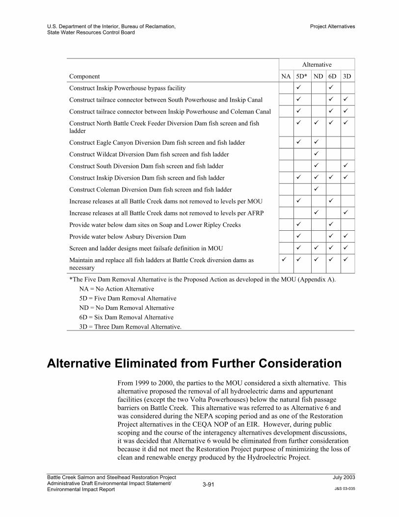
U.S. Department of the Interior, Bureau of Reclamation,State Water Resources Control Board
Project Alternatives
Battle Creek Salmon and Steelhead Restoration ProjectAdministrative Draft Environmental Impact Statement/Environmental Impact Report
3-91July 2003
J&S 03-035
Alternative
Component NA 5D* ND 6D 3D
Construct Inskip Powerhouse bypass facility
Construct tailrace connector between South Powerhouse and Inskip Canal
Construct tailrace connector between Inskip Powerhouse and Coleman Canal
Construct North Battle Creek Feeder Diversion Dam fish screen and fishladder
Construct Eagle Canyon Diversion Dam fish screen and fish ladder
Construct Wildcat Diversion Dam fish screen and fish ladder
Construct South Diversion Dam fish screen and fish ladder
Construct Inskip Diversion Dam fish screen and fish ladder
Construct Coleman Diversion Dam fish screen and fish ladder
Increase releases at all Battle Creek dams not removed to levels per MOU
Increase releases at all Battle Creek dams not removed to levels per AFRP
Provide water below dam sites on Soap and Lower Ripley Creeks
Provide water below Asbury Diversion Dam
Screen and ladder designs meet failsafe definition in MOU
Maintain and replace all fish ladders at Battle Creek diversion dams asnecessary
*The Five Dam Removal Alternative is the Proposed Action as developed in the MOU (Appendix A).NA = No Action Alternative5D = Five Dam Removal AlternativeND = No Dam Removal Alternative6D = Six Dam Removal Alternative3D = Three Dam Removal Alternative.
Alternative Eliminated from Further ConsiderationFrom 1999 to 2000, the parties to the MOU considered a sixth alternative. Thisalternative proposed the removal of all hydroelectric dams and appurtenantfacilities (except the two Volta Powerhouses) below the natural fish passagebarriers on Battle Creek. This alternative was referred to as Alternative 6 andwas considered during the NEPA scoping period and as one of the RestorationProject alternatives in the CEQA NOP of an EIR. However, during publicscoping and the course of the interagency alternatives development discussions,it was decided that Alternative 6 would be eliminated from further considerationbecause it did not meet the Restoration Project purpose of minimizing the loss ofclean and renewable energy produced by the Hydroelectric Project.

U.S. Department of the Interior, Bureau of Reclamation,State Water Resources Control Board
Project Alternatives
Battle Creek Salmon and Steelhead Restoration ProjectAdministrative Draft Environmental Impact Statement/Environmental Impact Report
3-92July 2003
J&S 03-035
The facilities proposed to be removed under Alternative 6 included:
North Battle Creek Feeder and flume; Digger Creek Feeder;
Cross Country Canal;
Eagle Canyon Diversion Dam and Canal;
Wildcat Diversion Dam, Pipeline, and Canal;
South Diversion Dam and Canal;
South Powerhouse;
Inskip Diversion Dam and Canal;
Inskip Powerhouse;
Coleman Diversion Dam, Canal, and Forebay;
Coleman Powerhouse;
Upper Ripley Creek Diversion and Pipeline;
Lower Ripley Creek Diversion and Canal;
Soap Creek Feeder and Pipeline;
Asbury Diversion Dam, Pumping Facility, and Pipeline; and
Pacific Power Diversion and Canal.
In addition to these Federal energy policy obstacles, Alternative 6 createdunintended economic consequences. Removal of all structures below the twoVolta powerhouses would likely have rendered the remaining portion of theHydroelectric Project uneconomic for PG&E to operate, thereby requiring theentire Hydroelectric Project (including those portions above the natural barriers)to be decommissioned. The total capacity of the Battle Creek HydroelectricProject, which consists of five powerhouses, is 36,056 kW. If, as described inAlternative 6, three of these powerhouses were decommissioned, approximately75%, or 26,550 kW, would be eliminated. The lost generating capacity wouldshut down the entire hydroelectric project because the cost to maintain theremaining facilities could not be recovered by the revenue received for the reducepower generation. Consequently, partial decommissioning as formulated in thealternative would likely lead to a full decommissioning of the complete project,including those facilities above the natural barriers.
This alternative would unnecessarily result not only in the loss of all energyproduced by the Hydroelectric Project, but would also have significant adverseeconomic impacts on the local community due to the loss of jobs at PG&E,which is a major employer in the community. A ripple effect would haveoccurred because the money earned and spent locally by PG&E employees turnsover many times within that local community.

U.S. Department of the Interior, Bureau of Reclamation,State Water Resources Control Board
Project Alternatives
Battle Creek Salmon and Steelhead Restoration ProjectAdministrative Draft Environmental Impact Statement/Environmental Impact Report
3-93July 2003
J&S 03-035
Therefore, because it does not meet the Restoration Project purpose,Alternative 6 has been eliminated from further consideration and will not bediscussed further.

Table 3-6. Prescribed Minimum Continuous Monthly Instream Flow Releases
Monthly Minimum Flow Release (cfs)Diversion Dam
Jan Feb Mar Apr May Jun Jul Aug Sep Oct Nov Dec
North Battle Creek Feeder
Five Dam Removal Alternative 1 88 88 88 67 47 47 47 47 47 47 47 88
No Dam Removal Alternative 40 40 40 40 30 30 30 30 40 40 40 40
Six Dam Removal Alternative 88 88 88 67 47 47 47 47 47 47 47 88
Three Dam Removal Alternative 40 40 40 40 30 30 30 30 40 40 40 40
Eagle Canyon
Five Dam Removal Alternative 2 46 46 46 46 35 35 35 35 35 35 35 46
No Dam Removal Alternative 50 50 50 50 30 30 30 30 30 30 30 50
Six Dam Removal Alternative Facility removed, no instream flow requirement
Three Dam Removal Alternative Facility removed, no instream flow requirement
Wildcat
Five Dam Removal Alternative Facility removed, no instream flow requirement
No Dam Removal Alternative 50 50 50 50 30 30 30 30 30 30 30 50
Six Dam Removal Alternative Facility removed, no instream flow requirement
Three Dam Removal Alternative Facility removed, no instream flow requirement
South
Five Dam Removal Alternative Facility removed, no instream flow requirement
No Dam Removal Alternative 30 30 30 30 20 20 20 20 20 20 20 30
Six Dam Removal Alternative Facility removed, no instream flow requirement
Three Dam Removal Alternative 30 30 30 30 20 20 20 20 20 20 20 30
Inskip
Five Dam Removal Alternative 3 86 86 86 61 40 40 40 40 40 40 40 86

Table 3-6. Continued Page 2 of 3
Monthly Minimum Flow Release (cfs)Diversion Dam
Jan Feb Mar Apr May Jun Jul Aug Sep Oct Nov Dec
No Dam Removal Alternative 40 40 40 40 30 30 30 30 30 30 30 40
Six Dam Removal Alternative 86 86 86 61 40 40 40 40 40 40 40 86
Three Dam Removal Alternative 40 40 40 40 30 30 30 30 30 30 30 40
Coleman
Five Dam Removal Alternative Facility removed, no instream flow requirement
No Dam Removal Alternative 50 50 50 50 30 30 30 30 50 50 50 50
Six Dam Removal Alternative Facility removed, no instream flow requirement
Three Dam Removal Alternative Facility removed, no instream flow requirement
Lower Ripley Creek
Five Dam Removal Alternative Facility removed, no instream flow requirement
No Dam Removal Alternative No instream flow requirement
Six Dam Removal Alternative Facility removed, no instream flow requirement
Three Dam Removal Alternative No instream flow requirement
Soap
Five Dam Removal Alternative Facility removed, no instream flow requirement
No Dam Removal Alternative No instream flow requirement
Six Dam Removal Alternative Facility removed, no instream flow requirement
Three Dam Removal Alternative No instream flow requirement
Asbury
Five Dam Removal Alternative 5 5 5 5 5 5 5 5 5 5 5 5
No Dam Removal Alternative No instream flow requirement
Six Dam Removal Alternative 5 5 5 5 5 5 5 5 5 5 5 5
Three Dam Removal Alternative 10 10 10 10 10 10 10 10 10 10 10 10

Table 3-6. Continued Page 3 of 3
Monthly Minimum Flow Release (cfs)Diversion Dam
Jan Feb Mar Apr May Jun Jul Aug Sep Oct Nov Dec
1 On occasion, the release is unattainable because the quantity of inflow reaching North Battle Creek Feeder Diversion Dam. Additional inflows to theNorth Battle Creek Feeder reach are occasionally received from the junction box of the Volta II Powerhouse tailrace and Cross Country Canal a shortdistance downstream.
2 Eagle Canyon Diversion Dam releases reported in this table include 10 cfs releases from Eagle Canyon Springs (those springs located downstream ofEagle Canyon Dam that were included in the Interim Flow Agreement between the Licensee and Reclamation.
3 The prescribed instream flow would be the total inflow in South Fork Battle Creek upstream of the South Powerhouse when the available inflow is lessthan the prescribed flow.
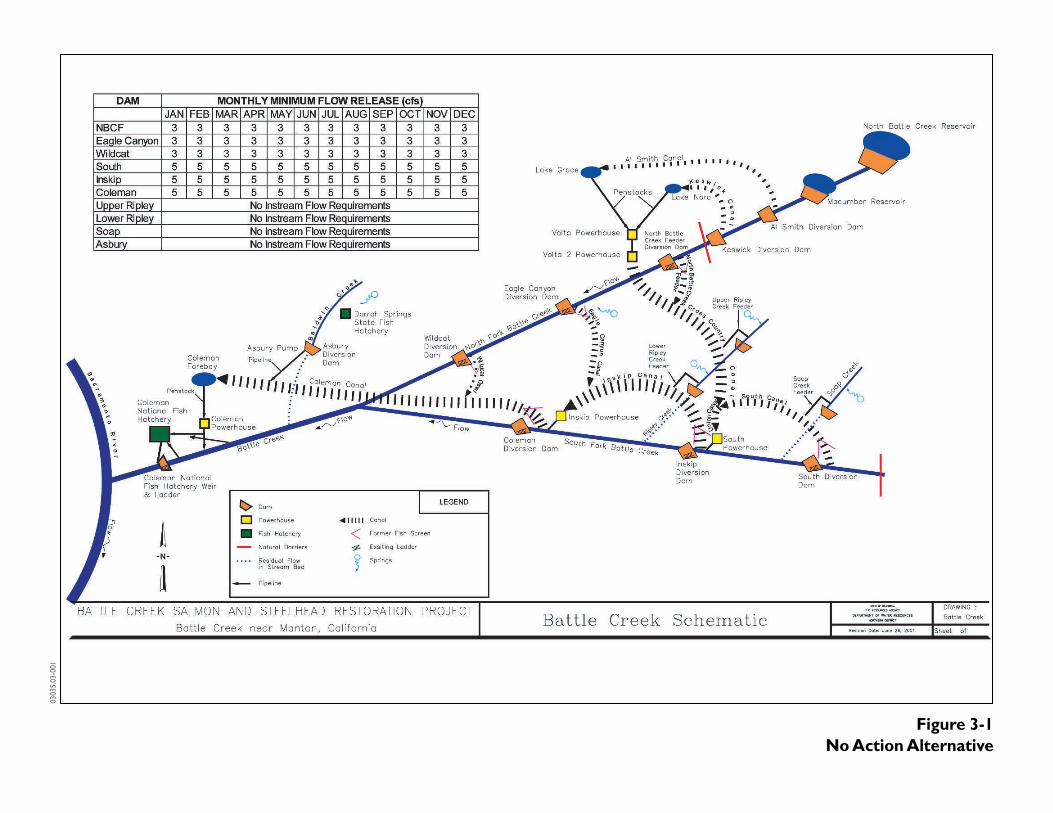
Figure 3-1No Action Alternative
0303
5.03
-001

Figure 3-2Five Dam Removal Alternative
0303
5.03
-001

Figure 3-2aProposed Facilities for the North Battle Creek Feeder Diversion Dam
Five Dam Removal Alternative
0303
5.03
001
No scale
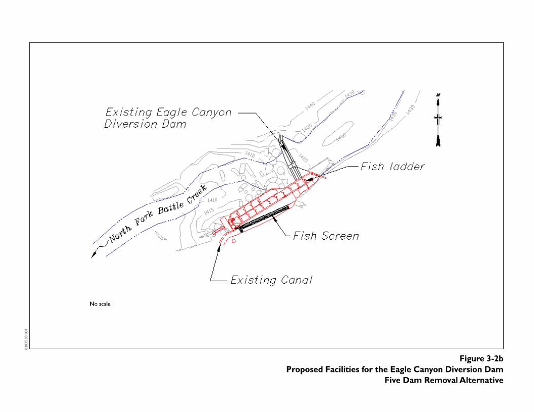
Figure 3-2bProposed Facilities for the Eagle Canyon Diversion Dam
Five Dam Removal Alternative
0303
5.03
001
No scale

0303
5.03
001
No scale
Figure 3-2cProposed Facilities for the Inskip Diversion Dam/South Powerhouse
Five Dam Removal Alternative

0303
5.03
001
No scale
Figure 3-2dProposed Facilities for the Coleman Diversion Dam/Inskip Powerhouse
Five Dam Removal Alternative

Figure 3-3No Removal Alternative
0303
5.03
-001

Figure 3-4Six Dam Removal Alternative
0303
5.03
-001

Figure 3-5Three Dam Removal Alternative
0303
5.03
-001