Embed Size (px)
Citation preview
Note.- Specifications concerning the siting and construc- tion ?f equipment and installations on operational areas aimed at reducing the hazard to aircraft to CI minimum are contained in Annex 13, Chapter 8.
3.1 Specification for ILS
3.1.1 Definitions
Angular &s&ucement sensifivify. The ratio of measured DDM to the corresponding angular displacement from the appropriate reference line.
Back course sector. The course sector which is situated on the opposite side of the localizer from the runway.
Course line. The locus of points nearest to the runway centre line in any horizontal plane at which the DDM is zero.
Course sector. A sector in a horizontal plane containing the course line and limited by the looi of points nearest to the course line at which the DDM is 0.155.
DDM - Difference in depth of modulation. The percentage modulation depth of the larger signal minus the percentage modulation depth of the smaller signal, divided by 100.
Displacement sensitivity (locah’zer). The ratio of measured DDM to the corresponding lateral displacement from the appropriate refe.rence line.
Facility Performance Category Z - ZLS. An ILS which provides guidance information from the coverage limit of the ILS to the point at which the localizer course line intersects the ILS glide path at a height of 60 m (200 ft) or less above thz horizontal plane containing the threshold.
Note.- This defmition is not intended to preclude the use of Facility Performance Cutegory I - ILS below the height of 60 m (200 ftj, with visual reference whew the quality of the guidance provided permits, and where satisfactov operational procedures have been established.
Facilify Performance Category II - ILS. in ILS which provides guidance information from the coverage limit of the ILS to The point at which the localizer course line intersects the XLS glide path at a height of 15 m (50 ftj or less above the shorizontal plane containing the threshold.
ANSEX 10 - VOLUME 1
CHAPTER 3. SPECIFICATIONS FOR RADIO NAVIGATION AIDS
Facility Performance Category IZZ - ZLS. An US which, with the aid of ancillary equipment where necessary, provides guidance information from the coverage Iimit of the facility to, and along. the surface of the mnway.
Front course sector. The course sector which is situated on the same side of the localizer as the runway.
Half course sector. The sector. in a horizontal plane containing the course line and limited by the loci of points nearest to the course line at which the DDM is 0.0775.
Half ZLS gZide path sector. The sector in the vertical plane containing the ILS glide path and limited by the loci of points nearest to the glide path at which the DDM is 0.0875.
ZLS continuiq of service. That quality which relates to the rarity of radiated signal interruptions. The level of continuiry of service of the localizer or the glide path is expressed in terms of the probability of not losing the radiated guidance siinals.
ZLS glide path. That locus of points in the vertical plane containing the runway centre line at which the DDM is zero, which, of all such loci. is the closest to the horizontal plane.
IL+!3 glide path angle. The angle between a straight line whjch represents the mean of the LLS glide path and the horizontal.
ILS glide path sector. The sector in the vertical plane containing the ILS glide path and limited by the loci of points nearest to the glide path at which the DDM is 0.175.
Note.- The ILS glide path sector is located in the vertical plune containing the runway centrc line, and is divided by the radiated glide puth in two parts called upper secmr und lower sectol; referring respectively to the sectors above and helonl the glide path.
ZLS integrity That quality which relates to the trust which can be placed in the correctness of the information supplied by the facility. The level of integrity of the localizer or the glide path is expressed in terms of the probability of not radiating false guidance signals.
ZLS Point ‘A”. A point on the ILS glide path measured along the extended runway centre line in the approach direction a distance of 7.5 km (4 NM) from the threshold.
4mi99 so. 74
Annex 10 - Aeronautical Telecommunications
ILS Point “BY A point on the ILS glide path measured along the extended runway centre line in the approach direction a distance of 1 050 m (3 500 ft) from the threshold.
ILS Point ‘%“. A point through which the downward extended straight portion of the nominal ILS glide path passes at a height of 30 m (100 ft) above the horizontal plane containing the threshold.
ES Point “‘D”‘. A point 4 m (12 ft) above the runway centre line and 900 m (3 000 ft) from the threshold in the direction of the localizer.
ZLS Point “‘E”. A point 4 m (12 ft) above the runway centre line and 600 m (2 000 ft) from the stop end of the runway in the direction of the threshold.
Note.- See Attachment C, Figure C-l.
ILS reference datum (Point “T’v. A point at a specified height located above the intersection of the runway centre line and the threshold and through which the downward extended straight portion of the ILS glide path passes.
Two-frequency glide path system. An ILS glide path in which coverage is achieved by the use of two independent radiation field patterns spaced on separate carrier frequencies within the particular glide path channel.
Two-frequency localizer system. A locaiizer system in which coverage is achieved by the use of two independent radiation field patterns spaced on separate carrier frequencies within the particular localizer VHF channel.
3.1.2 Basic requirements
3.1.2.1 The ILS shall comprise the following basic components:
VHF localizer equipment, associated monitor system, remote control and indicator equipment;
UHF glide path equipment, associated monitor system, remote control and indicator equipment;
VHF marker beacons, associated monitor systems, remote control and indicator equipment, except as provided in 3.1.7.6.6 below.
3.1.2.1.1 Facility Performance Categories I, II and III - ILS shall provide indications at designated remote control points of the operational status of all ILS ground system components.
Note l.- It is intended that the air trafjic services unit involved in the control of aircraf on the jinal approach be one of the designated control points receiving, without deluy, information on the operational stutus of the ILS as derived from the monitors.
4/11/99 No. 14
Volume I
Note 2.- It is intended that the uir trafic system is likely to call .for additional provisions which may be found essential
for the attainment of full operational Category III capability, e.g. to provide additional lateral and longitudinal guidance during the landing roll-out, and taxiing, and to ensure enhancement of the integrity und reliability of the system.
3.1.2.2 The ILS shall be constructed and adjusted so that, at a specified distance from the threshold, similar instrumental indications in the aircraft represent similar displacements from the course line or ILS glide path as appropriate, irrespective of the particular ground installation in use.
3.1.2.3 The localizer and glide path components specified in 3.1.2.1 a) and b) above which form part of a Facility Performance Category I - ILS shall comply at least with the Standards in 3.1.3 and 3.1.5 below respectively, excepting those in which application to Facility Performance Category II - ILS is prescribed.
3.1.2.4 The localizer and glide path components specified in 3.1.2.1 a) and b) above which form part of a Facility Performance Category II - ILS shall comply with the Standards applicable to these components in a Facility Performance Category I - ILS, as supplemented or amended by the Standards in 3.1.3 and 3.1.5 below in which application to Facility Performance Category II - ILS is prescribed.
3.1.2.5 The localizer and glide path components and other ancillary equipment specified in 3.1.2.1.1 above, which form part of a Facility Performance Category III - II& shah otherwise comply with the Standards applicable to these components in Facility Performance Categories I and II - ILS, except as supplemented by the Standards in 3.1.3 and 3.1.5 below in which application to Facility Performance Category III - ILS is prescribed.
3.1.2.6 To ensure au adequate level of safety, the ILS shall be so designed and maintained that the probability of operation within the performance requirements specified is of a high value, consistent with the category of operational performance concerned.
Note.- The specijications for Facility Performance Categories II and III - ILS are intended to achieve the highest degree of system integrit>: reliability und stability qf operation under the most adverse environmental conditions to be encountered. Guidance material to achieve this objective in Categories II und III operations is given in 2.8 oj- Attachment C.
3.1.2.7 At those locations where two separate ILS facilities serve opposite ends of a single runway, an interlock shall ensure that only the localizer serving the approach direction in use shall radiate, except where the localizer in operational use is Facility Performance Category I - ILS and no operationally harmful interference results.
6
Chapter 3 Annex 10 - Aeronautical Telecommunications
3.1.2.7.1 Recommendation.- At those locations where two separate ILS facilities serve opposite ends of a single runway and where a Facility Performance Category I - ILS is to be used for auto-coupled approaches and landings in visual conditions an interlock should ensure that only the localizer serving the approach direction in use radiates, providing the other localizer is not required for simultaneous operational use.
localizcr antenna system which provides the signals used in the front course sector.
3.1.3.2 Radio frequency
3.1.3.2.1 The localizer shall operate in the band 108 MHz to 111.975 MHz. Where a single radio frequency carrier is used, the frequency tolerance shall not exceed plus or minus 0.005 per cent. Where two radio frequency carriers are used, the frequency tolerance shall not exceed 0.002 per cent and the nominal band occupied by the carriers shall be symmetrical about the assigned frequency. With all tolerances applied, the frequency separation between the carriers shall not be less than 5 kHz nor more than 14 kHz.
Note.- If both localizers radiate there is a possibility of interference to the localizer signals in the threshold region. Additional guidance material is contained in 2.1.9 and 2.13 of Attachment C.
3.1.2.7.2 At locations where ILS facilities serving opposite ends of the same runway or different runways at the same airport use the same paired frequencies, an interlock shall ensure that only one facility shall radiate at a time. When switching from one ILS facility to another, radiation from both shall be suppressed for not less than 20 seconds.
Note.- Additional guidance material on the operation of localizers on the same frequency channel is contained in 2.1.9 of Attachment C and Volume V Chapter 4.
3.1.3 VHF localizer and associated monitor
3.1.3.2.2 The emission from the localizer shall be horizontally polarized. The vertically polarized component of the radiation on the course line shall not exceed that which corresponds to a DDM error of 0.016 when an aircraft is positioned on the course line and is in a roll attitude of 20 degrees from the horizontal.
3.1.3.2.2.1 For Pacility Performance Category II localizers, the vertically polarized component of the radiation on the course line shall not exceed that which corresponds to a DDM error of 0.008 when an aircraft is positioned on the course line and is in a roll attitude of 20 degrees from the horizontal.
Introduction. The specifications of this 3.1.3 cover ILS localizers providing either positive guidance information over 360 degrees of azimuth, or providing such guidance only within a specified portion of the front coverage (see 3.1.3.7.4 below). Where ILS localizers providing positive guidance information in a limited sector are installed. information from some suitably located navigation aid, together with appropriate procedures, will generally be required to ensure that any misleading guidance information outside the sector is not operationally significant.
3.1.3.2.2.2 For Facility Performance Category III localizers, the vertically polarized component of the radiation within a sector bounded by 0.02 DDM either side of the course line shall not exceed that which corresponds to a DDM error of 0.005 when au aircraft is in a roll attitude of 20 degrees from the horizontal.
- - 0.01 Hz to 10 Hz.
3.1.3.2.3 For Facility Performance Category III locahzers, signals emanating from the transmitter shall contain no components which result in an apparent course line fluctuation of more than 0.005 DDM peak to peak in the frequency band
3.1.3.1 General
3.1.3.1.1 The radiation from the localizer antenna system shall produce a composite field pattern which is amplitude modulated by a 90 Hz and a 150 Hz tone. The radiation field pattern shall produce a course sector with one tone predominating on one side of the course and with the other tone predominating on the opposite side.
3.1.3.3 Coverage
3.1.3.3.1 The localizer shall provide signals sufficient to allow satisfactory operation of a typical aircraft installation within the localizer and glide path coverage sectors. The localizer coverage sector shall extend from the centre of the localizcr antenna system to distances of:
3.1.3.1.2 When an observer faces the localizer from the approach end of a runway, the depth of modulation of the radio frequency carrier due to the 150 Hz tone shall predominate on his right hand and that due to the 90 Hz tone shall predominate on his left hand.
46.3 km (25 NM) within plus or minus 10 degrees from the front course line;
31.5 km (17 NM) between 10 degrees and 35 degrees from the front course line;
3.1.3.1.3 All horizontal angles employed in specifying the localizer field patterns shall originate from the centre of the
185 km (1,O NM) outside of plus or minus 35 degrees if coverage is provided;
7 4/11/99 No. 74
Annex 10 - Aeronautical Telecommunications Volume I
except that, where topographical features dictate or operational requirements permit, the limits may be reduced to 33.3 km (1X NM) within the plus or minus IO-degree sector and 18.5 km (10 NM) within the remainder of the coverage when alternative navigational facilities provide satisfactory coverage within the intermediate approach area. The localizer signals shall be receivable at the distances specified at and above a height of 600 m (2 000 ft) above the elevation of the threshold. or 300 m (1 000 ft) above the elevation of the highest point within the intermediate and final approach areas, whichever is the higher. Such signals shall be receivable, to the distances specified, up to a surface extending outward from the localizer antenna and inclined at 7 degrees above the horizontal.
Note I.- The requirements in 3.1.3.3.J, X1.3.3.2.1, 3.1.3.3.2.2 and 3.1.3.3.2.3 above are based on the assumption that the aircraft is heading directly toward the faciliq.
Note 2.- Guidance material on significant airborne receiver parameters is given in 2.2.2 and 2.2.4 of Attachment C.
3.1.3.3.4 When coverage is achieved by a localizer using two radio frequency carriers, one carrier providing a radiation field pattern in the front course sector and the other providing a radiation tield pattern outside that sector, the ratio of the two carrier signal strengths in space within the front course sector to the coverage limits specified at 3.1.3.3.1 above shall not be
Now- Guidance material on localizer coverage is given in 2. J. I I of Attachment C.
3.1.3.3.2 In all parts of the coverage volume specified in 3.1.3.3.1 above, other than as specified in 3.1.3.3.2.1, 3.1.3.3.2.2 and 3.1.3.3.2.3 below, the field strength shall be not less than 40 microvolts per metre (minus 114 dBW/m’).
Note.- This minimum field strength is required to permit satisfactory operational usage of ILS Iocalizer facilities.
3.1.3.3.2.1 For Facility Performance Category I localizers, the minimum field strength on the ILS glide path and within the localizer course sector from a distance of 18.5 km (10 NM) to a height of 60 m (200 ft) above the horizontal plane containing the threshold shall be not less than 90 microvolts per metre (minus 107 dBW/m’).
3.1.3.3.2.2 For Facility Performance Category II localizers, the minimum field strength on the ILS glide path and within the localizer course sector shall be not less than 100 microvolts per metre (minus 106 dBW/m’j at a distance of 18.5 km (10 NM) increasing to not less than 200 microvolts per metre (minus 100 dBW/m2) at a height of 15 m (50 ft) above the hotizontal plane containing the threshold.
3.1.3.3.2.3 For Facility Performance Category HI localizers, the minimum field strength on the ILS glide path and within the localizer course sector shall be not less than 100 microvolts per metre (minus 106 dBW/m’) at a distance of 18.5 km (10 NM), increasing to not less than 200 microvolts per metre (minus 100 dBW/m2) at 6 m (20 ft) above the horizontal plane containing the threshold. From this point to a further point 4 m (12 ft) above the runway centre line, and 300 m (1 Ooo ft) from the threshold in the direction of the localizer, and thereafter at a height of 4 m (12 ft) along the length of the runway in the direction of the localizer, the field strength shall be not less than 100 microvolts per metrc (minus 106 dBW/m”).
less than 10 dB.
Note.- Guidance material on localizers achieving coverage niith two radio frequency carriers is given in the Note to 3.1.3.11.2 below and in 2.7 of Attachment C.
3.1.3.3.5 Recommendation.- For Facility Performance Category III localizers, the ratio of the two carrier signal strengths in space within the front course sector should not he less than 16 dB.
3.1.3.4 Course structure
3.1.3.4.1 For Facility Performance Category I localizers, bends in the course line shall not have amplitudes which exceed the following:
Zone Amplitude (DDM) (95% probability)
Outer limit of coverage to ILS Point “A” 0.031
ILS Point ‘A” to ILS Point “B”
0.031 at ILS Point ‘A” decreasing at a
linear rate to 0.015 at ILS Point “B”
ILS Point “B” to ILS Point “c” 0.015
3.1.3.4.2 For Facility Performance Categories II and III localizers, bends in the course line shall not have amplitudes which exceed the following:
Zone Amplitude (DDM) (95% probabilityj
Outer limit of coverage to ILS Point “A” 0.03 1
Note.- The field strengths given in 3.1.3.3.2.2 and 3.1.3.3.2.3 above are necessary to provide the signal-to-noise ratio required for improved integrity.
3.1.3.3.3 Recommendation.- Above 7 degrees, the signals should be reduced to as low a value as practicable.
ILS Point “‘A*’ to ILS Point “B”
ILS Point “B” to the ILS reference datum
0.031 at ILS Point ‘A” decreasing at a linear rate to
0.005 at ILS Point “B”
0.005
4/U/99 8 No. 74
Chapter 3
and, for Category III only:
JLS reference datum to ILS Point “D” 0.005
ILS Point “D’ to ILS 0.005 at ILS Point “D” Point “IT’ increasing at a linear rate to
0.010 at ILS Point “E”
Note I.- The amplitudes referred to in 3.1.3.4.1 and 3.1.3.4.2 above are the DDMs due to bends as realized on the mean course line, when correctly adjusted.
Note 2.- Guidance material relevant to the localizer course structure is given in 2.1.4, 2.1.6 and 2.1.7 of Attachment C.
3.1.3.5 Carrier modulation
3.1.3.5.1 The nominal depth of modulation of the radio frequency carrier due to each of the 90 Hz and 150 Hz tones shall be 20 per cent along the course line.
3.1.3.5.2 The depth of modulation of the radio frequency carrier due to each of the 90 Hz and 150 Hz tones shall be within the limits of 18 and 22 per cent.
3.1.3.5.3 The following tolerances shall be applied to the frequencies of the modulating tones:
a) the modulating tones shall be 90 Hz and 150 Hz within plus or minus 2.5 per cent;
b) the modulating tones shall be 90 Hz and 150 Hz within plus or minus 1.5 per cent for Facility Performance Category II installations;
c) the modulating tones shall. be 90 Hz and 150 Hz within plus or minus 1 per cent for Facility Performance Category III installations;
d) the total harmonic content of the 90 Hz tone shall not exceed 10 per cent; additionally, for Facility Performance Category III localizers, the second harmonic of the 90 Hz tone shall not exceed S per cent;
e) the total harmonic content of the 150 Hz tone shall not exceed 10 per cent.
3.1.3.5.3.1 Recommendation.- For Facility Pe$ormance Category I - KS, the modulating tones should be 90 Hz and 150 Hz within plus or minus 1.5 per cent where practicable.
3.1.3.5.3.2 For Facility Performance Category III local- izers, the depth of amplitude modulation of the radio frequency carrier at the power supply frequency or its harmonics, or by other unwanted components, shall not exceed 0.5 per cent. Harmonics of the supply, or other unwanted noise
Annex 10 - Aeronautical Telecommunications
components that may intermodulate with the 90 Hz and 150 Hz navigational tones or their harmonics to produce fluctuations in the course line, shall not exceed 0.05 per cent modulation depth of the radio frequency carrier.
3.1.3.5.3.3 The modulation tones shall be phase-locked so that within the half course sector, the demodulated 90 Hz and 150 Hz wave forms pass through zero in the same direction within:
a) for Facility Performance Categories I and II localizers: 20 degrees: and
b) for Facility Performance Category III localizers: IO degrees,
of phase relative to the 150 Hz component, every half cycle of the combined 90 Hz and 150 Hz wave form.
Note l.- The definition of phase relationship in this manner is not intended to imply a requirement to measure the phase within the half course sectoK
Note 2.- Guidance material relative to such measurement is given at Figure C-6 of Attachmen.t C.
3.1.3.5.3.4 With two-frequency Iocalizer systems, 3.1.3.5.3.3 above shall apply to each carrier. In addition, the 90 Hz modulating tone of one carrier shall be phase-locked to the 90 Hz modulating tone of the other carrier so that the demodulated wave forms pass through zero in the same direction within:
a) for Categories I and II localizers: 20 degrees; and
b) for Category III localizers: 10 degrees,
of phase relative to 90 Hz. Similarly, the 150 Hz tones of the two carriers shall be phase-locked so that the demodulated wave forms pass through zero in the same direction within:
1) for Categories I and II localizers: 20 degrees; and
2) for Category III localizers: 10 degrees,
of phase relative to 150 Hz.
3.1.3.5.3.5 Alternative two-frequency localizer systems that employ audio phasing different from the normal inphase conditions described in 3.1.3.5.3.4 above shall be permitted. In this alternative system, the 90 Hz to 90 Hz phasing and the 150 Hz to 150 Hz phasing shall be adjusted to their nominal values to within limits equivalent to those stated in 3.1.3.5.3.4 above.
Note.- This is to ensure correct airborne receiver operation in the region away from the course line where the two carrier signal strengths are appro.ximat+ equal.
9 4/1l/YY No.74
Annex 10. - Aeronautical Telecommunications
3.1.3.1X3.6 Recommendation.- The sum of the modu- lation depths of the radio frequency carrier due to the 90 Hz and I50 Hz tones should not exceed 60 per cent or be less than 30 per cent within the required coverage.
3.1.3.5.3.6-l For equipmenl first installed after 1 January 2000, the sum of the modulation depths of the radio frequency carrier due to the 90 Hz and 150 Hz tones shall not exceed 60 per cent or be less than 30 per cent within the required coverage.
Note I.- I f the sum of the modulation depths is greater than 60 per cent jkr Facility Perfarmance Categoqj I localizers, the nominal displacement sensitivity may be adjusted as provided for in 3.I.3.7.1 to achieve the above modulation limit.
Note 2.- For two-frequenq systems, the standard for maximum sum of modulation depths does not apply at or near azimuths where the course and clearance carrier signal levels are equal in amplitude (i.e. at azimuths where both transmitting systems have a signzfkant contribution to the total modulation depth).
Note 3.- The standard for minimum sum of modulation depths is based on the malfunctioning alarm level being set as high as 30 per cent as stated in 2.3.3 of Attachmerxt C.
3.1.3.5.3.7 When utilizing a localizer for radiotelephone communications, the sum of the modulation depths of the radio frequency carrier due to the 90 Hz and 150 Hz tones shall not exceed 65 per cent within IO degrees of the course line and shall not exceed 78 per cent at any other point around the localizer.
3.1.3.5.4 Recommendation.- Undesired frequency and phase modulation on ILS localizer radio frequency carriers that can affect the displayed DDM values in localizer receivers should be minimized to the extent practical.
Note.- Relevant guidance material is given in 2.15 of Attachment C.
3.1.3.6 Course alignment accurao
3.1.3.6.1 The mean course line shall be adjusted and maintained within limits equivalent to the folIowing displacements from the runway centre line at the ILS reference datum:
a) for Facility Performance Category I localizers: plus or minus 10.5 m (35 ft), or the linear equivalent of 0.015 DDM, whichever is less;
b) for Facility Performance Category II localizers: plus or minus 7.5 m (25 ft);
Volume I
c) for Facility Performance Category III localizers: plus or minus 3 m (10 ft).
3.1.3.6.2 Recommendation.- For Facility Pe$ormance Category II localizers. the mean course line should be adjusted and maintained within limits equivalent to plus or minus 4.5 III (15 ft) displacement from runway centre line at the ILS reference datum.
Note I.- It is intended that Facility Pe$ormance Categories II and III installations be adjusted and maintained so that the limits spec!jied in 3.1.3.6.1 and 3.1.3.6.2 above are reached on very rare occasions. It is further intended that design and operation of the total IL..Y ground system be of suficient integrig to accomplish this aim.
Note 2.- It is intended that new Categov Ii installations are to meet the requirements of 3.1.3.6.2 above.
Note 3.- Guidunce material on measurement of localizer course alignment is given in 2.1.4 of Attachment C.
3.1.3.7 Displacement sensitivih’
3.1.3.7.1 The nominal displacement sensitivity within the half course sector at the ILS reference datum shall be 0.00145 DDM/m (0.00044 DDM/ft) except that for Category I localizers, where the specified nominal displacement sensitivity cannot be met, the displacement sensitivity shall be adjusted as near as possible to that value. For Facility Performance Category I localizers on runway codes 1 and 2, the nominal displacement sensitivity shall be achieved at the ILS Point “B”. The maximum course sector angle shall not exceed 6 degrees.
Note.- Runway codes I and 2 are defined in Annex 14.
3.1.3.7.2 The lateral displacement sensitivity shall be adjusted and maintained within the limits of plus or minus:
a) 17 per cent of the nominal value for Facility Performance Categories I and II;
b) 10 per cent of the nominal value for Facility Performance Category III.
3.1.3.7.3 Recommendation.- fib;or Faciliv Performance Category II -KS, displacement sensitivity should be adjusted and maintained within the limits of plus or minus IO per cent where practicable.
Note I.- The jigures given in 3.1.3.7.1, 3.1.3.7.2 and 3.1.3.7.3 above are based upon a nominal sector width of 210 m (700 ft) at rhe appropriate point, i.e. ILS Point “B” on runway codes 1 and 2, and the ILS rqference datum on other runways.
4/11/99 No. 74
.Chpter 3.
Note 2.- Guidance material on the alignment and displucemenr sensitiviy of localizers using two radio frequency carriers is given in 2.7 ?f Attuchment C.
Note J.- Guidance material on measurement of localizer displacement sensitivity is given in 2.9 of Attachment C.
3.1.3.7.4 The increase of DDM shall be substantially linear with respect to angular displacement from the front course line (where DDM is zero) up to an angle on either side of the front course line where the DDM is 0.180. From that angle to plus or minus 10 degrees, the DDM shall not be less than 0.180. From plus or minus 10 degrees to plus or minus 35 degrees, the DDM shall not be less than 0.155. U’here coverage is required outside of the plus or minus 35 degrees sector, the DDM in the area of the coverage, except in the back course sector, shall not be less than 0.155.
Note l.- The linearity of change of DDM with respect to angular displacement is particularly important in the neighbourhood of the course line.
Note 2.- The above DDM in the IO-35 degree sector is to be considered a minimum requirement for the use of fL.Y as a landing aid. Wherever practicuble a higher DDM, e.g. 0.180, is advantageous to assist high speed aircraft to execute large angle intercqts at operationally desirable distances provided that limits on modulation percentage given in 3.1.3.5.3.6 are met.
Note 3.- Wherever practicable, the localizer caphtre level of automatic flight control systems is to be set at or below 0.175 DDM in order to prevent false localizer captures.
3.1.3.8 Voice
3.1.3.8.1 Facility Performance Categories I and II localizers may provide a ground-to-air radiotelephone communication channel to be operated simultaneously with the navigation and identification signals, provided that such operation shall not interfere in any way with the basic localizer function.
3.1.3.8.2 Category III localizers shall not provide such a channel, except where extreme care has been taken in the design and operation of the facility to ensure that there is no possibility of interference with the navigational guidance.
3.1.3.8.3 If the channel is provided, it shall conform with the following Standards:
3.1.3.8.3.1 The channel shall be on the same radio frequency carrier or carriers as used for the localizer function, and the radiation shall be horizontally polarized. Where two carriers are modulated with speech. the relative phases of the modulations on the two carriers shall be such as to avoid the occurrence of nulls within the coverage of the localizer.
Annex IO - Aeronautical Telecommunications
3.1.3X3.2 The peak modulation depth of the carrier or carriers due to the radiotelephone communications shall not exceed 50 per cent but shall be adjusted so that:
a) the ratio of peak modulation depth due to the radio- telephone communications to that due to the identifi- cation signal is approximately 9:l;
b) the sum of modulation components due to use of the radiotelephone channel, navigational signals and identification signals shall not exceed 95 per cent.
3.1.3.8.3.3 The audio frequency characteristics of the radiotelephone channel shall be flat to within 3 dB relative to the level at 1 000 ‘Hz over the range 300 Hz to 3 000 Hz.
3.1.3.9 Identification
3.1.3.9.1 The localizer shall provide for the simultaneous transmission of an identification signal, specific to the runway and approach direction, on the same radio frequency carrier or carriers as used for the localizer function. The transmission of the identification signal shall not interfere in any way with the basic localizer function.
3.1.3.9.2 The identification signal shall be produced by Class A2A modulation of the radio frequency carrier or carriers using a modulation tone of 1 020 Hz within plus or minus 50 Hz. The depth of modulation shall be between the limits of 5 and 15 per cent except that, where a radiotelephone communication channel is provided, the depth of modulation shall be adjusted so that the ratio of peak modulation depth due to radiotelephone communications to that due to the identification signal modulation is approximately 9:l (see 3. I .3.X.3.2 above). The emissions carrying the identification signal shall be horizontally polarized. Where two carriers are modulated with identification signals, the relative phase of the modulations shall be such as to avoid the occurrence of nulls within the coverage of the localizer.
3.1.3.9.3 The identification signal shall employ the International Morse Code and consist of two or three letters. It may be preceded by the International Morse Code signal of the letter Y”, followed by a short pause where it is necessary to distinguish the ILS facility from other navigational facilities in the immediate area.
3.1.3.9.4 The identification signal shall be transmitted by dots and dashes at a speed corresponding to approximately seven words per minute, and shall be repeated at approximately equal intervals, not less than six times per minute, at all times during which the localizer is available for operational use. When the transmissions of the localizer are not available for operational use, as, for example, after removal of navigational components, or during maintenance or test transmissions, the identification signal shall be suppressed. The dots shall have a duration of 0.1 second to 0.160 second. The dash duration shall be typically three times the duration of
11 4111199 No. 74
Annex 10 - Aeronautical Telecommunications
a dot. The interval between dots and/or dashes shall be equal to that of one dot plus or minus 10 per cent. The interval between letters shall not be less than the duration of three dots.
3.1.3.10 Siting
3.1.3.10.1 The localizer antenna system shall be located on the extension of the centre line of the runway at the stop end, and the equipment shall be adjusted so that the course lines will be in a vertical plane containing the centre line of the runway served. The antenna system shall have the minimum height necessary to satisfy the coverage requirements laid down in 3.1.3.3 above, and the distance from the stop end of the runway shall be consistent with safe obstruction clearance practices.
3.1.3.11 Monitoring
3.1.3.11.1 The automatic monitor system shall provide a warning to the designated control points and cause one of the following to occur, within the period specified in 3.1.3.11.3.1 below! if any of the conditions stated in 3.1.3.11.2 below persists:
a)
bj
c)
radiation to cease;
removal of the navigation and identification components from the carrier;
reversion to a lower category in the case of Facility Performance Categories II and III localizers where the reversion requirement exists.
Note.- It is intended that the alternative of reversion offered in 3.1.3.1.1.1 above may be used only if
1) the safety of the reversion procedure has been substantiated: and
2) the means of providing informution to the pilot on the change of category has adequate integrity.
3.1.3.11.2 The conditions requiring initiation of monitor action shall be the following:
a) for Facility Performance Category I localizers, a shift of the mean course line from the runway centre line equivalent to more than 10.5 m (35 ft), or the linear equivalent to 0.015 DDM, whichever is less, at the ILS reference datum;
b) for Facility Performance Category II localizers, a shift of the mean course line from the runway centre line equivalent to more than 7.5 m (25 ft) at the ILS reference datum;
Volume I.
c) for Facility Performance Category III localjzers, a shift of the mean course line from the runway centre line equivalent to more than 6 m (20 ft) at the ILS reference datum:
d) in the case of localizers in which the basic functions are provided by the use of a single-frequency system, a reduction of power output to less than 50 per cent of normal. provided the localizer continues to meet the requirements of 3.1.3.3, 3.1.3.4 and 3.1.3.5 above;
e) in the case of localizers in which the basic functions are provided by the use of a two-frequency system, a reduction of power output for either carrier to less than 80 per cent of normal, except that a greater reduction to between 80 per cent and 50 per cent of normal may be permitted, provided the localizer continues to meet the requirements of 3.1.3.3, 3.1.3.4 and 3.1.3.5 above;
Note.- It is important to recognize that a frequency change resulting in a loss of the frequency diSference specified in 3.1.3.2.1 above may produce a hazardous condition. This problem is of ,greater operational signi$cance for Categories IJ and III instullutions. As necsssa?, this problem can be dealt with through special monitoring provisions or highly reliable circuitry
f) change of displacement sensitivity to a value differing by more than 17 per cent from the nominal value for the localizer facility.
Nore.- In selecting rhe power reduction figure to be employed in monitoring referred to in. 3.1.3.11.2 E) above, particular attention is directed to vertical and horizontal lobe structure (vertical lobing due to different antenna heights) of the combined radiation systems when two carriers are employed. Large changes in the power ratio between carriers may result in low clearance areas and false courses in the off- course areas to the limits of the vertical coverage requirements specjfied in 3.1.3.3.1 above.
3.1.3.11.2.1 Recommendation.- In the case of localizers in which the basicfunctions are provided by the use of a two-frequenq system, the conditions requiring initiation of monitor uction should include the case when the DDM in the required coverage beyond plus or minus 10 degrees from the front course line, except in the back cozme sector, decreases below 0.155.
3.1.3.11.3 The total period of radiation, including period(s) of zero radiation, outside the performance limits specified in a), b), c), d), ej and f) of 3.1.3.11.2 above shall be as short as practicable, consistent with the need for avoiding interruptions of the navigation service provided by the localizer.
4/l 1199 12 No. 74
Chapter 3
3.1.3.11.3.1 The total period referred to under 3.1.3.11.3 shall not exceed under any circumstances:
10 seconds for Category I localizers;
5 seconds for Category II localizers;
2 seconds for Category III localizers.
Note 1.- The total time periods spec$ed are rtever-to-be- exceeded limits and are intended to protect aircraft in the final stages sf approach aguinst prolonged or repeated pep-iods of locaker guidance outside the monitor limits. For this reason, they include not only the initial period 0~. outside tolerance operation but also the total sf any or all periods qf outside tolerance radiation including period(s) of zero radiation, which might occur during action to restore service, for example, in the course of consecutive ntorlitor fil?rctiolling and consequent change-owr(s) to localizer equipment or elements thereof
Note 2.- From an operational point of view, the intention is that no guidance outside the monitor limits be radiated after the time periods given, and that no filrther attempts be made to restore service until a period in the order of 20 seconds has elapsed.
3.1.3.11.3.2 Recommendation.- Where practicable, the total period under 3.1.3. J 1.3.1 should be reduced so as not to exceed two seconds for Cutegoyy II localizers and one second for Carego? 111 locali:ers.
3.1.3.11.4 Design and operation of the monitor system shall be consistent with the requirement that navigation guidance and identification will be removed and a warning provided at the designated remote control points in the event of failure of the monitor system itself.
Note.- Guidance material on the design and operation of monitor systems is given in Attachment C, 2.1.8.
3.1.3.11 S Any erroneous navigation signals on the carrier occuming during removal of navigation and identification components in accordance with 3.1.3.11 .I bj shall be suppressed within the total periods allowed in 3.1.3.11.3.1.
Note.- To prevent hazardous fluctuations in the radiated signal, localizers employing mechanical modulation equip- rnent may require suppression of navigation components during modulator rundown.
3.1.3.12 Integrity and continuiq Qf service requirements
3.1.3.12.1 The probability of not radiating false guidance signals shall not be less than 1 - 0.5 x 10s9 in any one landing for Facility Performance Categories II and III localizers.
Annex 10 - Aeronautical Telecommunications
3.1.3.12.2 Recommendation.- The probability of not radiating false guidance signals should not be less than I - 1.0 x JK7 in any one landing for Facilit?, Performance Categov I loculizers.
3.1.3.12.3 The probability of not losing the radiated guidance signal shall be greater than:
a) 1 - 2 x 10s6 in any period of 15 seconds for Facility Performance Category II localizers or localizers intended to be used for Category III .4 operations (equivalent to 2 000 hours mean time between outages); and
b) 1 - 2 x lo-” jn any period of 30 seconds for Facility Performance Category III localizers intended to be used for the full range of Category III operations (equivalent to 4 000 hours mean time between outages).
3.1.3.12.4 Recommendation.- The prohabili~ of nor losing the radiated guidan.ce signal should exceed .I - 4 x 10d in uny period (I$ 15 seconds forFacilir;\ Pe@ormance Categor )I locali,-ers (equivalent to I 000 hours mean time between outages).
Note.- Guidance materiol on integrity and continuity sf service is given in Attachment C, 2.8.
3.1.4 Interference immunity performance for ILS localizer receiving systems
3.1.3.1 After 1 January 1998, the ILS localizer receiving system shall provide adequate immunity to interference from two-signal, third-order intermodulation products caused by VHF FM broadcast signals having levels in accordance with the following:
2N, + NY + 72 5 0
for VHF FM sound broadcasting signals in the range 107.7 - 108.0 MHz
and
2N, + N2 + 3 i
24-20 log&; ) SO
for VHF FM sound broadcasting signals below 107.7 MHz,
where the frequencies of the two VHF FM sound broadcasting signals produce, within the receiver, a two-signal, third-order intermodulation product on the desired ILS localizer frequency.
N, and N! are the levels (dBm) of the two VHF FM sound broadcastmg signals at the ILS localizcr receiver input. Neither level shall exceed the desensitization criteria set forth in 3.1.4.2.
13 l/11/01 No. 76
Annex 10 - Aeronautical Telecommunications
Af = IO%.1 - f,, where fl is the frequency of N,, the VHF FM sound broadcasting signal closer to 108.1 MHz.
3.1.4.2 After 1 January 1998, the ILS localizer receiving system shall not be desensitized in the presence of VHF FM broadcast signals having levels in accordance with the following table:
Frequency (MHz)
Maximum level of unwanted signal at receiver input
Wm)
88-102 +15 104 +lO 106 t-5 107.9 -10
Note I.- The relationship is linear between adjacent points designated by the above frequencies.
Note 2.- Guidance material on immunity criteria to be used for the performance quoted in 3.1.4.1 and 3.1.4.2 above is contained in Attachment C, 2.2.9.
3.1.4.3 After 1 January 1995, all new installations of airborne ILS localizer receiving systems shall meet the provisions of 3.1.4.1 and 3.1.4.2 above.
3.1.4.4 Recommendation.- Airborne ILS Eocalizer receiving systems meeting the immunir; pe$ormance standards of 3.1.4.1 and 3.1.4.2 above should be placed into operation at the earliest possible date.
3.1.5 UHF glide path equipment and associated monitor
Note.- 8 is used in this paragraph to denote the nominal glide path angle.
3.1.5.1. General
3. I .5.1.1 The radiation from the UHF glide path antenna system shall produce a composite field pattern which is amplitude modulated by a 90 Hz and a 150 Hz tone. The pattern shall be arranged to provide a straight line descent path in the vertical plane containing the centre line of the runway, with the 150 Hz tone predominating below the path and the 90 Hz tone predominating above the path to at least an angle equal to 1.75 9.
3.1.5.1.2 Recommendation.- The UHF glide path equipment should be capable of adjustment to produce a radiated glide path from 2 to 4 degrees with respect to the horizontal.
3.1.5.1.2.1 Recommendation.- The IU glide path angle should be 3 degrees. ILS glide path angles in excess of
Volume I-
3 degrees should not be used except where alternative means of sati&ing obstruction clearance requirements are impracticable.
3.1.5.1.2.2 The glide path angle shall be adjusted and maintained within:
a) 0.075 9 from 8 for Facility Performance Categories I and II - ILS glide paths:
b) 0.04 6 from e for Facility Performance Category III - ILS glide paths.
Note I.- Guidance material on adjustment and maintenance of glide path angles is given in 2.4 of Attach- ment C.
Note 2.- Guidance materiul on ZLS glide path curvature, alignment and siting, relevant to the selection oj’ the height of the ILS reference dutum is given in 2.4 of Attachment C and Figure C-5.
3.1.5.1.3 The downward extended straight portion of the ILS glide path shall pass through the ILS reference datum at a height ensuring safe guidance over obstructions and also safe and effkient use of the runway served.
3.1.5.1.4 The height of the ILS reference datum for Facility Performance Categories II and III - ILS shall be 15 m (50 ft). A tolerance of plus 3 m (10 ft) is permitted.
3.1.5.1.5 Recommendation.- The height of the ILS reference datum for Facility Performance Category I - KS should be 15 m (50 ft). A tolerance of plus 3 m (10 ft) is permitted.
Note I.- In arriving at the above height values for the ILS reference datum, a maximum vertical distance of 5.8 m (19.ft) between the path of the aircraft glide path antenna and the path sf the lowest part of the wheels at the threshold was assumed. For aircraft exceeding this criterion, appropriate steps may have to be taken either to maintain adequute clearance at threshold or to adjust the permitted operating minima.
Note 2.- Appropriate guidance muterial is given in 2.4 of Attachment C.
3.1.5.1.6 Recommendation.- The height qf the ILS reference dahlm for Facility Pelformance Categov I - ILS used on short precision approach runway codes 1 and 2 should be 12 m (40.7). A tolerance of plus 6 m (2Ofi) is permitted.
3.1.5.2 Radio freqtiency
3.1.5.2.1 The glide path equipment shall operate in the band 328.6 MHz to 335.4 MHz. Where a single radio frequency carrier is used, the frequency toIerance shall not
4flll99 14 No. 14
Chapter3 Annex 10 - Aeronautical Xelecommunications
exceed 0.005 per cent. Where two carrier glide path systems are used, the frequency tolerance shall not exceed 0.002 per cent and the nominal band occupied by the carriers shall be symmetrical about the assigned frequency. With all tolerances applied, the frequency separation between the carriers shall not be less than 4 kHz nor more than 32 kHz.
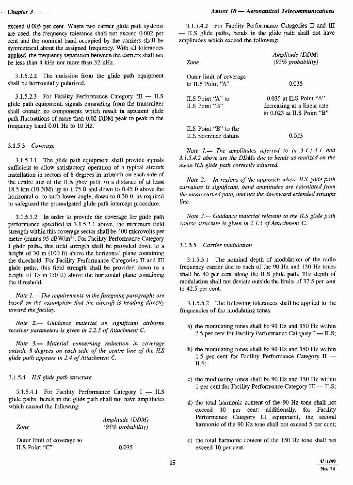
3.1.5.4.2 For Facility Performance Categories II and III - ILS glide paths, bends in the glide path shall not have amplitudes which exceed the following:
3.1.5.2.2 The emission from the glide path equipment shall be horizontally polarized.
3.1.5.2.3 For Facility Performance Category III - ILS glide path equipment, signals emanating from the transmitter shall contain no components which result in apparent glide path fluctuations of more than 0.02 DDM peak to peak in the frequency band 0.01 Hz to 10 Hz.
Zone
Outer limit of coverage to ILS Point ‘A”
ILS Point ‘A” to ILS Point “B”
‘Amplitude (DDM) (95% probability)
0.035
0.035 at ILS Point ‘A” decreasing at a linear rate to 0.023 at ILS Point “B”
3.1.5.3 Coverage
3.1.5.3.1 The glide path equipment shall provide signals sufficient to allow satisfactory operation of a typical aircraft installation in sectors of 8 degrees in azimuth on each side of the centre line of the ILS glide path, to a distance of at least 18.5 km (10 NM) up to 1.75 8 and down to 0.45 0 above the horizontal or to such lower angle, down to 0.30 0, as required to safeguard the promulgated glide path intercept procedure.
ILS Point “B” to the ILS reference datum 0.023
Note I.- The amplitudes referred to in 3.1.5.4.1 and 3.1.5.4.2 above are the DDMs due to bends as realized on the mean ILS glide path correctly adjusted.
Note 2.- In regions of the approach where ILS glide path curvature is significant, bend amplitudes are calculated from the meun curved path, and not the dawnward extended straight line.
3.1.5.3.2 In order to provide the coverage for glide path performance specified in 3.1 S.3.1 above, the minimum field strength within this coverage sector shall be 400 microvolts per metre (minus 95 dBW/m2). For Facility Performance Category I glide paths, this field strength shall be provided down to a height of 30 m (100 ft) above the horizontal plane containing the threshold. For Facility Performance Categories II and III glide paths, this field strength shall be provided down to a height of 15 m (50 ft) above the horizontal plane containing the threshold.
Note 3.- Guidance material relevant to the ILS glide path course structure is given in 2.1.5 of Attuchment C.
3.1.5.5 Carrier modulation
3.1.5.5.1 The nominal depth of modulation of the radio frequency carrier due to each of the 90 Hz and 150 Hz tones shall be 40 per cent along the ILS glide path. The depth of modulation shall not deviate outside the limits of 37.5 per cent to 42.5 per cent.
Note I.- The requirements in the foregoing paragraphs are based on the assumption that the aircraft is heading directl! toward the .fucility.
3.1.5.5.2 The following tolerances shall be applied to the frequencies of the modulating tones:
Note 2.- Guidance materiul on significant airborne receiver parameters is given in 2.2.5 of Attachment C. the modulating tones shall be 90 Hz and 150 Hz within
2.5 per cent for Facility Performance Category I - ILS: Note 3.- Material concerning reduction in coverage
outside 8 degrees on each side qf the centre line of the IL.7 glide path appears in 2.4 of Attachment C.
b) the modulating tones shall be 90 Hz and 150 Hz within 1.5 per cent for Facility Performance Category II - ILS;
3.1.5.4 KS glide path structure
3.1.5.4.1 For Facility Performance Category I - ILS glide paths, bends in the glide path shall not have amplitudes which exceed the following:
Cl the modulating tones shall be 90 Hz and 150 Hz within 1 per cent for Facility Performance Category III - ILS;
4
Zone
Outer limit of coverage to ILS Point “C’
Amplitude (DDMj (95% probabilityj
0.035
the total harmonic content of the 90 Bz tone shall not exceed 10 per cent: additionally, for Facility Performance Category III equipment, the second harmonic of the 90 Hz tone shall not exceed 5 per cent;
e) the total harmonic content of the 150 Hz tone shall not exceed 10 per cent.
15 4/u/99 No.74
Annex 10 - Aeronautical Telecommunications
3.1.5.5.2.1 Recommendation.- For Futility Pelformance Categov I - KS, the modulating tones should be 90 Hz and 1.50 Hz within plus or minus 1.5 per cent where practicable.
3.1.5.5.2.2 For Facility Performance Category III glide path equipment, the depth of amplitude modulation of the radio frequency carrier at the power supply frequency or harmonics, or at other noise frequencies, shall not exceed 1 per cent.
3.1.5.5.3 The modulation shall be phase-locked so that within the ILS half glide path sector, the demodulated 90 Hz and 150 Hz wave forms pass through zero in the same direction within:
a) for Facility Performance Categories I and II - ILS glide paths: 20 degrees;
b) for Facility Performance C.ategory III - ILS glide paths: 10 degrees,
of phase relative to the 150 Hz component, every half cycle of the combined 90 Hz and 150 Hz wave form.
Note I.-- The definition of phase relationship in this manner is not intended to imply a requirement for measurement of phase within the ILS half glide path sector
Note 2.- Guidance material relating to such measures is given at Figure C-6 of Attachment C.
3.1.5.5.3.1 With two-frequency glide path systems, 3.1.5.5.3 above shall apply to each carrier. In addition, the 90 Hz modulating tone of one carrier shall be phase-locked to the 90 Hz modulating tone of the other carrier so that the demodulated wave forms pass through zero in the same direction within:
aj for Categories I and II - ILS glide paths: 20 degrees;
bj for Category III - ILS glide paths: 10 degrees,
of phase relative to 90 Hz. Similarly, the 150 Hz tones of the two carriers shall be phase-locked so that the demodulated wave forms pass through zero in the same direction, within:
1) for Categories I and II - ILS glide paths: 20 degrees;
2) for Category III - ILS glide paths: 10 degrees,
of phase relative to 150 Hz.
3.1.5.5.3.2 Alternative two-frequency glide path systems that employ audio phasing different from the normal inphase condition described in 3.1.5.5.3.1 above shall be permitted. In these alternative systems, the 90 Hz to 90 Hz phasing and the 150 Hz to 150 Hz phasing shall be adjusted to their nominal values to within limits equivalent to those stated in 3.1.5.5.3.1 above.
4/11/w No.74
Volume I
Note.- This is to ensure correct airborne receiver operation within the glide path sector where the two carrier signal strengths are approximately equal.
3.1.5.5.4 Recommendation.- Undesired frequency and phase modulation on ILS glide path radio frequency carriers that can a#ect the displayed DDh4 values in glide path receivers should be minimized to the extent practical.
Note.- Relevant guidance material is given in 2.15 of Attachment C.
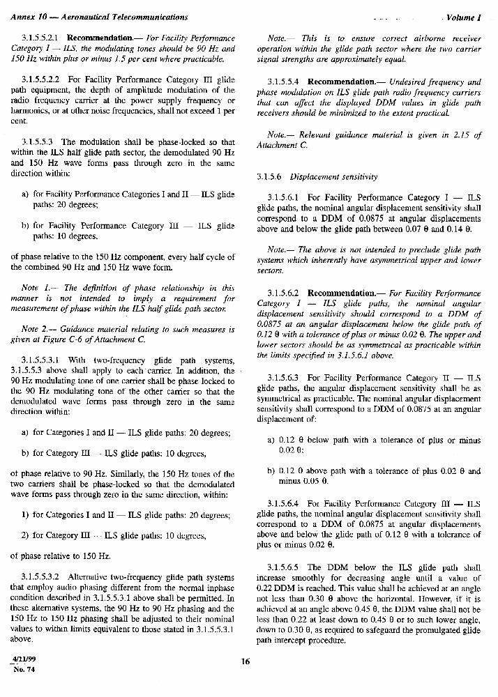
3.1.5.6 Displacement sensitivity
3.1.5.6.1 For Facility Performance Category I - ILS glide paths, the nominal angular displacement sensitivity shall correspond to a DDM of 0.0875 at angular displacements above and below the glide path between 0.07 8 and 0.14 0.
Note.- The above is not intended to preclude glide path systems which inherently have asymmetrical upper and lower sectors.
3. I .5.6.2 Recommendation.- For Facility Performance Category I - JLS glide paths, the nominal angular displacement sensitivity should correspond to a DDh4 of 0.0875 at an angular displacement below the glide path of 0.12 0 with a tolerance ofplus or minus 0.02 8. The upper and lower sectors should be as symmetrical as practicable within the limits spectfied in 3.1.5.6.1 above.
3.1.5.6.3 For Facility Performance Category II - ILS glide paths, the anguhar displacement sensitivity shall be as symmetrical as practicable. The nominal angular displacement sensitivity shall correspond to a DDM of 0.0875 at an angular displacement of:
a) 0.12 e below path with a tolerance of plus or minus 0.02 8;
b) 0.12 8 above path with a tolerance of plus 0.02 8 and minus 0.05 8.
3.1.5.6.4 For Facility Performance Category III - ILS glide paths, the nominal angular displacement sensitivity shall correspond to a DDM of 0.0875 at angular displacements above and below the glide path of 0.12 0 with a tolerance of plus or minus 0.02 8.
3.1.5.6.5 The DDM below the ILS glide path shall increase smoothly for decreasing angle until a value of 0.22 DDM is reached. This value shall be achieved at an angle not less than 0.30 0 above the horizontal. However, if it is achieved at an angle above 0.45 9, the DDM value shall not be less than 0.22 at least down to 0.45 t3 or to such lower angle, down to 0.30 8, as required to safeguard the promulgated glide path intercept procedure.
16
Chapter 3
Nore. - The 1im.it.s of glide path equipment adjustment are pictorially represented in Figure C-11 of Attachment C.
3.1.5.6.6 For Facility Performance Category I - ILS glide paths, the angular displacement sensitivity shall be adjusted and maintained within plus or minus 25 per cent of the nominal value selected.
3.1.5.6.7 For Facility Performance Category Il - ILS glide paths, the angular displacement sensitivity shall be adjusted and maintained within plus or minus 20 per cent of the nominal value selcctcd.
3.1.5.6.X For Facility Performance Category III - ILS glide paths, the angular displacement sensitivity shall be adjusted and maintained within plus or minus 15 per cent of the nominal value selected.
Note.- G14idu~zce mutcrial on ILS glide path adjustment and maintenance values is given in Aitachment C, 2.1.5.
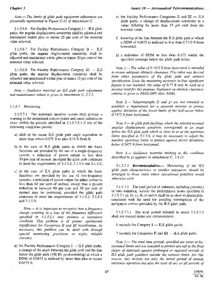
3.1.5.1 Monitoring
3.1.5.7.1 The automatic monitor system shall provide a warning to the designated control points and cause radiation to cease within the periods specified in 3.1.5.7.3.1 if any of the following conditions persist:
a) shift of the mean lLS glide path angle equivalent to more than minus 0.075 8 to plus 0.10 9 from 8;
b) in the case of ILS glide paths in which the basic functions are provided by the use of a single-frequency system, a reduction of power output to less than 50 per cent of normal. provided the glide path continues to meet the requirements of 3.1.5.3. 3.1.5.4 and 3.1.5.5;
c) in the case of ILS glide paths in which the basic funclions are provided by the use of Iwo-frequency systems, a reduction of power output for either carrier to less than 80 per cent of normal. except that a greater reduction to between X0 per cent and 50 per cent of normal may be permitted, provided the glide path continues to meet the requirements of 3.1.5.3, 3.1.5.4 and 3.1.5.5:
Note.- It is important to recogn.i;e that a fkquency change resulting in a loss of the jkquency d@et-ence speci?kd in 3.1.5.2.1 may produce a ha;urdorls condttion. This problem is of greater operarional signijicunce .for Categories II and III insrallutions. As necessar?;, this problem can be dealt with through special monitoring provisions or highl? reliable circuitn:
d) for Facility Performance Category I - ILS glide paths, a change of the angle between the glide path and the line below the glide path (150 Hz predominating) at which a DDM of 0.0875 is realized by more than plus or minus 0.0375 8;
Annex 10 - Aeronautical Telecommunications.,
for Facility Perforrnancc Categories II and III - ILS glide paths, a change of displacement sensitivity to a value differing by more than 25 pet cent from the nominal value;
lowering of the line beneath the ILS glide path at which a DDlM of 0.0875 is realized to less than 0.7475 0 from horizontal;
a reduction of DDM to less than 0.175 within the specified coverage below the glide path sector.
Note I.- The value of 0.7475 0.fi-om horizontal is intended to ensure adequate obstacle clearance. This value was derived from other parameters of the glide path and monitor specification. Since the measuring accurucy to four significant jigures is not intended, the value of 0.7-5 0 tnuy be used as a monirol- limit for rhtr pzcrpose. Guidance on obstack clearance criteria is given in PANS-OPS (Dot 8168).
Note 2.- Subparagraphs ,f) and g) ure not intended to establish a requirement for a separate monitor to protect againnst deviation qf the lower Iimits of rhe half-sector below 0.7475 0 from horizontal.
Note 3.-At glide path facilities where the selected nominal angulur displacement sensitivic corresponds to an a~zgle below the TLS glide path u$bhirh is close bo or ar the nz&nzum limits spec$ied in 3.1.5.6, it may he )lecessay to adjust the monitor operating kmits to protect uguinst sector deviation,r below 0.7475 8 .fro?n hori:on.tal.
Note 4.- Guidaxe material reluting to the condirion described in gi appears in Attachment C. 2.413.
3.1.5.7.2 Recommendation.- Monitoring of the IL.5 glide path churucteristrcs to smaller tolerances should be arranged in those cases where operational penalties would otherwise exist.
3.1.5.7.3 The total period of radiation, including period(s) of zero radiation, outside the. performance limits specified in 3.1.5.7. I a), bj. c), d), e) and f) shall be as short as practicable. consistent with the need for avoiding interruptions of the navigation service provided by the ILS glide path.
3.1.5.7.3.1 The total period referred to under 3.1.5.7.3 shall not exceed under any circumstances:
6 seconds for Category I - ILS glide paths;
2 seconds for Categories II and III - ILS glide paths.
Note I.- The total time periods spec$ed are never-ro-be- exceeded limits and are intended to protect aircrafr in the final stages oj* approacfz against prolonged or repeated periods qf ILS glide parh guidance outside the monitor limits. For this reason, they in.clude not only the initiul period of outside tolerance operation but also the total of any or all periods of
17 1/11/01 No. 76
Annex 10 - Aeronautical Telecommunications
outside toletunce radiation, including period(s) of zero radiation, which might occur during action to restore service, for example, in the course of consecutive monitor functioning and consequent chan,geover(s) to glide path equipment(s) or elements there@
Note 2.- From an operational pokt qf view, the intention is that no guidance outside the monitor lim.its be radiated after the time periods given, and that no further attempts be made to restore service until a period in the order of 20 seconds has elapsed.
3.1 S.7.3.2 Recommendation.- Where practicable, the total period specified under 3.1.5.7.X I above for Categories II and III - ILS glide paths should not exceed 1 second.
3.1.5.7.4 Design and operation of the monitor system shall be consistent with the requirement that radiation shall cease and a warning shall be pi-ovided at the designated remote control points in the event of failure of the monitor system itself.
Note.- Guidance material on the design and operation. sf monitor systems is given in 2.1.8 of Attachment C.
3.1.5.8 Integrit): and continuity of serx?ce requirements
3.1.5.8.1 The probability of not radiating false guidmce signals shall not be less than 1 - 0.5 x 10B9 in any one landing for Facility Performance Categories II and III glide paths.
3.1.5.8.2 Recommendation.- The probability of not radiating false guidance signals should not be less than I - 1.0 x lop7 in any one landing.for Facility Performance Categop I glide paths.
3.1.5.8.3 The probability of not losing the radiated guidance signal shall be greater than 1 - 2 x lop6 in any period of IS seconds for Facility Performance Categories II and III glide paths (equivalent to 2 000 hours mean time between outages).
3.1.5.R.4 Recommendation.- The probabilitl: of not losing the radiated guidance signal should exceed I - 4 x ifl in any period of 1.5 seconds for Faciliv Pet$onnance Category I glide paths (equivalent to 1 000 hozrrs meun tim.e between outuges).
Note.- Guidance nwterial on integrity and continuity of service is given in 2.8 of Attachment C.
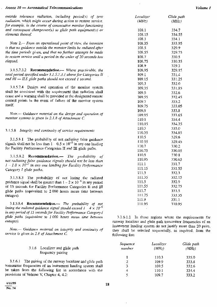
3.1.6 Localizer and glide path frequency pairing
3.1.6.1 The pairing of the runway localizer and glide path Wansmitter frequencies of an instrument landing system shall be taken from the following list in accordance with the provisions of Volume V, Chapter 4, 4.2:
Eocalizer Glide path (MHz) (MHZ)
108.1 334.7 108.15 334.55 108.3 334.1 108.35 333.95 108.5 329.9 108.55 329.75 108.7 330.5 108.75 330.35 108.9 329.3 108.95 329.15 109.1 331.4 109.15 331.25 109.3 332.0 109.35 331.85 109.5 332.6 109.55 332.45 109.7 333.2 109.75 333.05 109.9 333.8 109.95 333.65 110.1 334.4 110.15 334.25 110.3 335.0 110.35 334.85 I1 0.5 329.6 110.55 329.45 110.7 330.2 110.75 330.05 110.9 330.8 110.95 330.65 111.1 331.7 111.15 331.55 111.3 332.3 111.35 332.15 111.5 332.9 111.55 332.75 111.7 333.5 111.75 333.35 111.9 331.1 111.95 330.95
Volume I
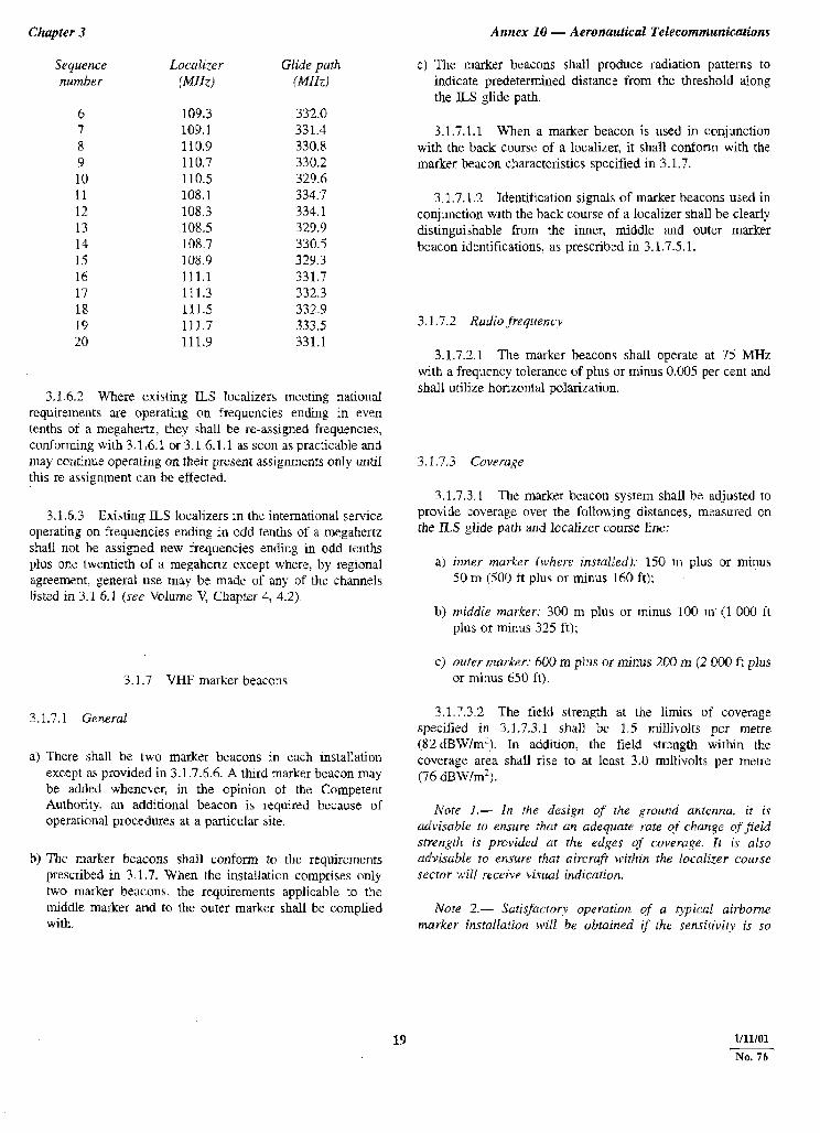
3.1.6.1.1 In those regions where the requirements for runway localizer and glide path transmitter frequencies of an instrument landing system do not justify more than 20 pairs, they shall be selected sequentially, as required, from the following list:
Sequence Localizer Glide path number (MHz) (MHz)
1 110.3 335.0 2 109.9 333.8 3 109.5 332.6 4 110.1 334.4 5 109.7 333.2
4/11/33 18 No. 71
Chapter 3 Amex 10 - Aeronautical Telecommunications
Sequence nunther
Loculizer Glide puth (MHz) !MHZ)
6 109.3 332.0 7 109.1 331.4 8 110.9 330.X 9 110.7 330.2 10 110.5 329.4 II 108.1 334.7 1.2 108.3 334.1 13 108.5 329.4 14 108.7 330.5 15 108.9 329.3 16 111.1 331.7 17 111.3 332.3 18 111.5 332.9 19 111.7 333.5 20 111.9 331.1
3.1.6.2 Where existing KS localizers meeting national requirements are operating on frequencies ending in even tenths of a megahertz, lhcy shall be reassigned frequencies, conforming with 3.1.6.1 or 3.1.6.1 .l as soon as practicable and may continue operating on their present assignments only until this re-assignment can be effected.
3.1.6.3 Existing ILS localizers m the international service operating on frequencies ending in odd tenths of a megahertz shall not he assigned new frequencies ending in odd tenths plus or,e twentieth of a megahcrlz except where, by regional agreement. general use may be made of any of the channels listed in 3.1.6.1 (see Volume V, Chapter 4, 4.2).
3.1.7 VHF marker beacons
3.1.7.1 General
a) There shall be two marker beacons in each installation except as provided in 3.1.7.6.6. A third marker beacon may be added whenever, in the opinion of the Competent Authority: an additional beacon is required because of operational procedures at a particular site.
b) The marker beacons shall conform to the requirements prescribed in 3.1.7. When the installation comprises only two marker beacons, the requirements applicable to the middle marker and to the outer marker shall be complied with.
c) The marker beacons shall produce radiation patterns to indicate predetermined distance from the threshold along the ILS glide path.
3.1.7.1.1 When a marker beacon is used in conjunction with the back course of a localizer, it shall conform with the marker beacon c!laractcristics specified in 3.1.7.
3.1.7.1.2 Identification signals of marker beacons used in conjunction with the back course of a localizer shall be clearly distinguishable from :he inner, middle and outer marker beacon identifications, as prescribed in 3.1.7.5.1.
3.1.7.2 Radio “frequency
3.1.7.2.1 The marker beacons shall operate at 75 MHz with a freqllcncy tolerance of plus or minus 0.005 per cenl and shall utilize horizontal polarization.
3.1.7.3 Coverage
X1.7.3.1 The marker beacon system shall be adjusted to provide coverage over the following distances, measured cn the IL5 glide path and Iccalizer course line:
a) inner marker (where installed): 150 m plus or minus 50 m (500 ft plus or minus 160 ft):
b) middle marker: 300 m plus or minus 100 m (1 000 It plus or minus 325 ft);
cj outer rcrrker: 600 m plus or minus 200 m (2 000 f: plus or minus 650 fi).
3.1.7.3.2 The field strength at the limits of coverage specified in 3.1.7.3.1 shall ‘be 1.5 millivolts per metre (82 &W/m’). In addition, the field strength within the coverage area shall rise to at least 3.0 millivolts per metre (76 dBW/m”).
Note I.- In the design of the ground antenna, it is advisable to ensure that an adequate rate c$ change of field stren;gth is provided ar the edges of coveraye. It is also advisable to ensure rhat aircrqfr within the local&r course sector will receive visual indication.
Nore 2.- Sotisfacron: operation of a qpical airborne murker instnllation will be obtained if the sensiriGty is su
19 l/11101 No.76