Embed Size (px)
Citation preview
Chapter 3
SUBSOIL EXPLORATION

Prof. Abdullah I. Almhaidib
عبدهللا بن إبراهيم المهيدب . د.أ
Office: 2A-56
Office hours: As posted
Phone: 467-7033
email: [email protected]
Website: http://fac.ksu.edu.sa/muhaidib

1st Mid-term Exam: Tuesday 8/10/2019G
2nd Mid-term Exam: Monday 18/11/2019G
(after Maghreb Prayer)
Soil does not posses a unique or linear stress-strainrelationship.
Soil behavior depends upon the pressure, time andenvironment.
Soil at every location is essentially different.
Nearly in all the cases, the mass of soil involved isunderground and cannot be seen entirely, but must beevaluated on the basis of small size samples, obtainedfrom isolated locations.
Most soils are very sensitive to disturbance fromsampling and thus the behavior measured by a lab testmay be unlike that of in situ soil.
GENERAL OBSERVATION
SUBSOIL EXPLORATION
• Natural soil deposits are not homogeneous, elastic, or isotropic.In some places, the stratification of soil deposits may changegreatly within a short horizontal distance.
• For foundation design and construction work, one must knowthe actual soil stratification at a given site, the laboratory testresults of the soil samples obtained from various depths, andthe observations made during the construction of otherstructures built under similar conditions.
• For most major structures, adequate subsoil exploration at theconstruction site must be conducted.
DEFINITION OF SUBSOIL EXPLORATION
The process of determining the layers of natural
soil deposits that will underlie a proposed
structure and their physical properties
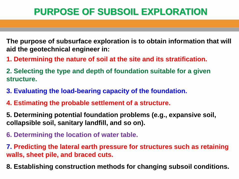
PURPOSE OF SUBSOIL EXPLORATION
The purpose of subsurface exploration is to obtain information that will
aid the geotechnical engineer in:
1. Determining the nature of soil at the site and its stratification.
2. Selecting the type and depth of foundation suitable for a given
structure.
3. Evaluating the load-bearing capacity of the foundation.
4. Estimating the probable settlement of a structure.
5. Determining potential foundation problems (e.g., expansive soil,
collapsible soil, sanitary landfill, and so on).
6. Determining the location of water table.
7. Predicting the lateral earth pressure for structures such as retaining
walls, sheet pile, and braced cuts.
8. Establishing construction methods for changing subsoil conditions.
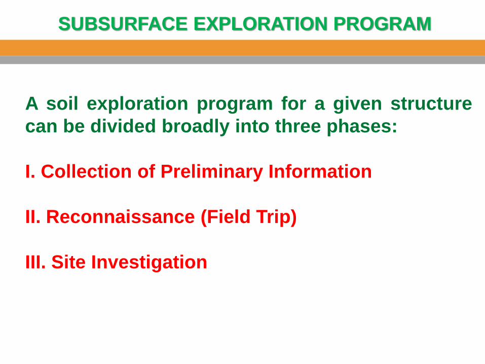
SUBSURFACE EXPLORATION PROGRAM
A soil exploration program for a given structure
can be divided broadly into three phases:
I. Collection of Preliminary Information
II. Reconnaissance (Field Trip)
III. Site Investigation

This step includes obtaining information regarding the type
of structure to be built and its general use.
For the construction of building:
The approximate column loads and their spacing.
Local building-codes.
Basement requirement.
For the construction of bridge:
The length of their spans.
The loading on piers and abutments.
It also includes obtaining information regarding the general
topography and type of soil to be encountered near and
around the proposed site which can be obtained from
Saudi Geological Survey and other sources.
السعودية المساحة الجيولوجية هيئة www.sgs.org.sa
I. Collection of Preliminary Information
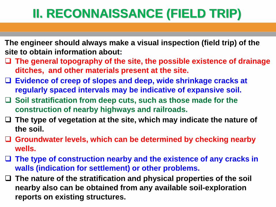
The engineer should always make a visual inspection (field trip) of the
site to obtain information about:
The general topography of the site, the possible existence of drainage
ditches, and other materials present at the site.
Evidence of creep of slopes and deep, wide shrinkage cracks at
regularly spaced intervals may be indicative of expansive soil.
Soil stratification from deep cuts, such as those made for the
construction of nearby highways and railroads.
The type of vegetation at the site, which may indicate the nature of
the soil.
Groundwater levels, which can be determined by checking nearby
wells.
The type of construction nearby and the existence of any cracks in
walls (indication for settlement) or other problems.
The nature of the stratification and physical properties of the soil
nearby also can be obtained from any available soil-exploration
reports on existing structures.
II. RECONNAISSANCE (FIELD TRIP)
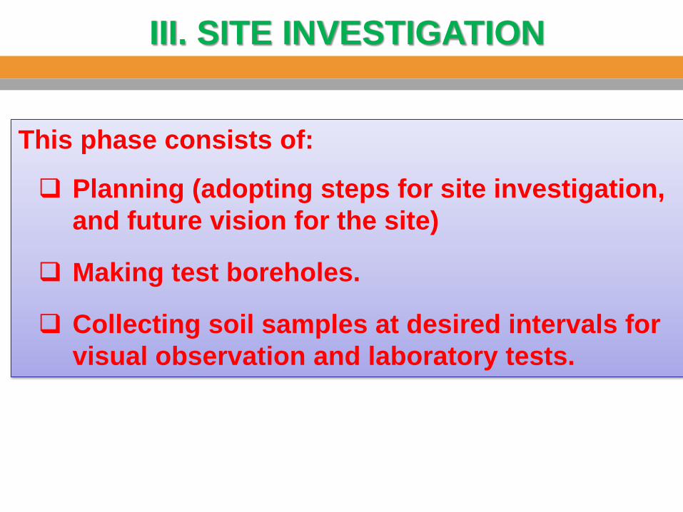
This phase consists of:
Planning (adopting steps for site investigation,
and future vision for the site)
Making test boreholes.
Collecting soil samples at desired intervals for
visual observation and laboratory tests.
III. SITE INVESTIGATION
Soil Boring:
Test Pits
Auger Boring
SITE INVESTIGATION
Test Pits:
• Open excavation (1.5-2.5 deep & approximate 1 m wide)
• Suitable for near surface evaluation, sampling and testing
• Visual inspection
• Excavated by hand or machine
• For small projects where foundation level < 2 m
• Block samples
• For preliminary investigation
• It is relatively fast and inexpensive
Determining the number of boring:
• There is no hard-and-fast rule exists for determining the number of
borings are to be advanced.
• For most buildings, at least one boring at each corner and one at the
center should provide a start.
• Spacing can be increased or decreased, depending on the condition
of the subsoil.
• If various soil strata are more or less uniform and predictable, fewer
boreholes are needed than in nonhomogeneous soil strata.
Approximate Spacing of Boreholes
Spacing (m) Type of project
10–30 Multistory building
20–60 One-story industrial plants
250–500 Highways
250–500 Residential subdivision
40–80 Dams and dikes
NUMBER OF BORING
EXAMPLE
In practice:
number of boreholes and the depth of each
borehole will be identified according to the type
of project and the subsoil on site.
Example for a 5 story residential building with
dimensions of (40 x 70) m:
The required number of boreholes = 5
boreholes (one at each corner and one at the
center) as mentioned previously.
The figure shows the distribution of boreholes
on the land
Determining the depth of boring: The approximate required minimum depth of the borings should be predetermined. The
estimated depths can be changed during the drilling operation, depending on the subsoil
encountered (e.g., Rock).
To determine the approximate required minimum depth of boring, engineers may use the rules
established by the American Society of Civil Engineers (ASCE 1972):
1. Determine the net increase in effective stress (Δσ′) under a foundation with depth.
2.Estimate the variation of the vertical effective stress (σo′) with depth.
3. Determine the depth (D = D1) at which the effective increase
(q = estimated net stress on the foundation).
4. Determine the depth (D = D2) at which
5. Determine the depth (D = D3) which is the distance
from the lower face of the foundation to bedrock
(if encountered).
6. Choose the smaller of the three depths (D1, D2, and D3)
is the approximate required minimum depth of boring.
After determining the value of (D) as explained above,
the final depth of boring (from the ground surface to the
calculated depth) is:
Because the drilling will start from the ground surface.
Δσ′ σo′
DEPTH OF BORING
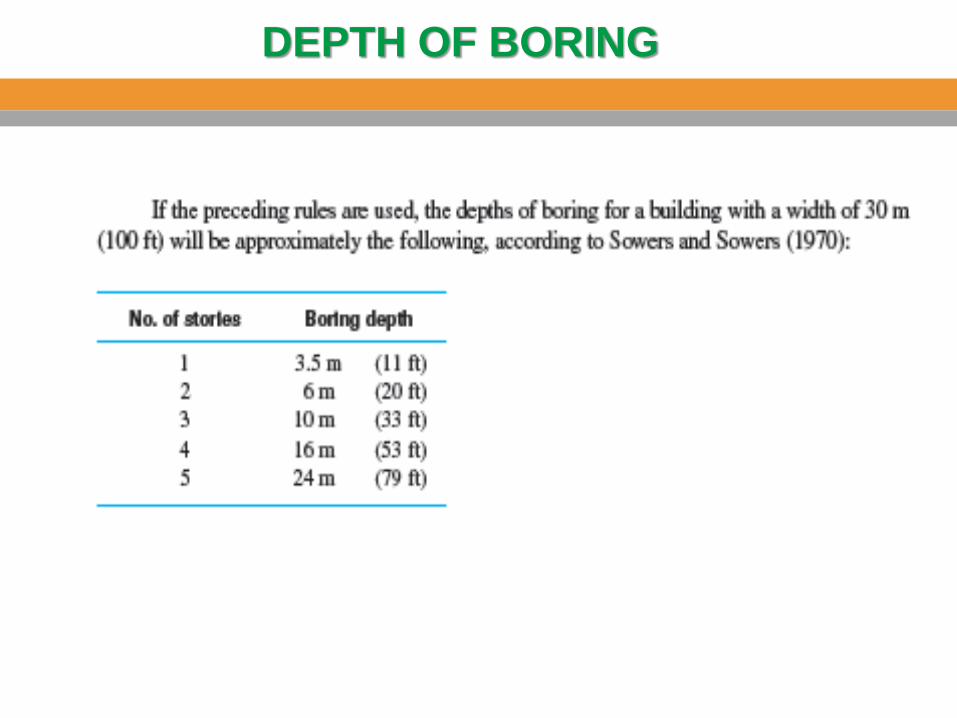
DEPTH OF BORING
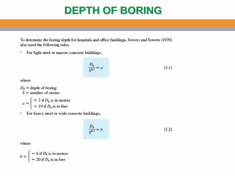
DEPTH OF BORING
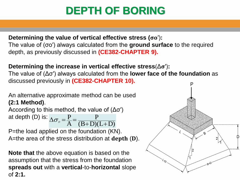
Determining the value of vertical effective stress (𝛔𝐨′):
The value of (σo′) always calculated from the ground surface to the required
depth, as previously discussed in (CE382-CHAPTER 9).
Determining the increase in vertical effective stress(Δ𝛔′):
The value of (Δσ′) always calculated from the lower face of the foundation as
discussed previously in (CE382-CHAPTER 10).
An alternative approximate method can be used
(2:1 Method).
According to this method, the value of (Δσ′)
at depth (D) is:
P=the load applied on the foundation (KN).
A=the area of the stress distribution at 𝐝𝐞𝐩𝐭𝐡 (𝐃).
Note that the above equation is based on the
assumption that the stress from the foundation
spreads out with a vertical-to-horizontal slope
of 2:1.
D)D)(L(BP
AP
D
DEPTH OF BORING
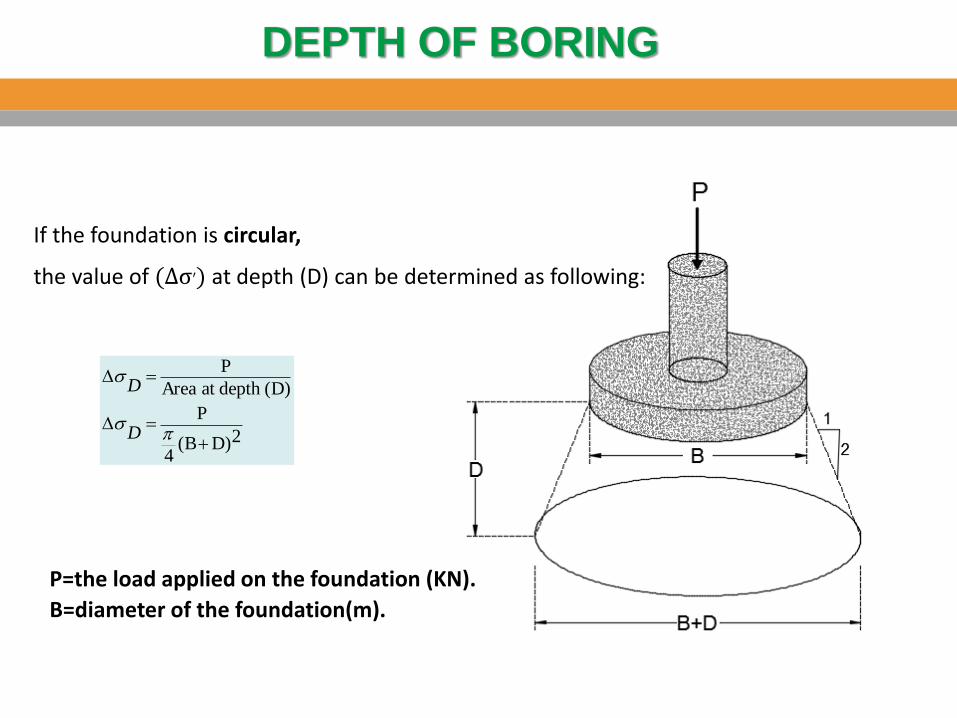
P=the load applied on the foundation (KN).
B=diameter of the foundation(m).
2D)(B4
P
(D)depth at Area
P
D
D
If the foundation is circular,
the value of (Δσ′) at depth (D) can be determined as following:
DEPTH OF BORING
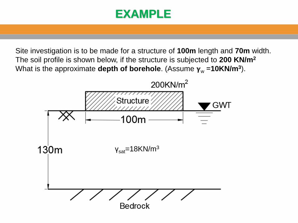
Site investigation is to be made for a structure of 100m length and 70m width.
The soil profile is shown below, if the structure is subjected to 200 KN/m2
What is the approximate depth of borehole. (Assume 𝛄w =10KN/m3).
EXAMPLE
γsat=18KN/m3
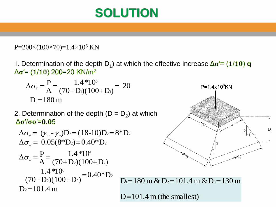
SOLUTION
P=200×(100×70)=1.4×10⁶ KN
1. Determination of the depth D1) at which the effective increase
2. Determination of the depth (D = D2) at which
m 180 D
20 )D)(100D(70
10* 1.4
AP
1
11
6
D
22
222
D*0.40)D*0.05(8
D*8 10)D-(18 D) -(
D
wsato
m 101.4 D
D*40.0)D)(100D(70
10* 1.4
)D)(100D(7010* 1.4
AP
2
2
22
6
22
6
D
smallest) (the m 101.4D
m 130 D& m 101.4 D & m 180 D 321
METHODS OF BORING
The boring methods are used for exploration at greater depths where
direct methods fail. They provide both disturbed as well as undisturbed
samples depending upon the method of boring.
In selecting the boring method for a particular job, consideration should
be made for the following:
•The materials to be encountered and the relative efficiency of the
various boring methods in such materials
•The available facility and accuracy with which changes in the soil and
ground water conditions can be determined
•Possible disturbance of the material to be sampled
METHODS OF BORING
The different types of boring methods are:
1. Auger boring
2. Continuous sampling
3.Wash boring
4. Rotary drilling
5. Percussion drilling
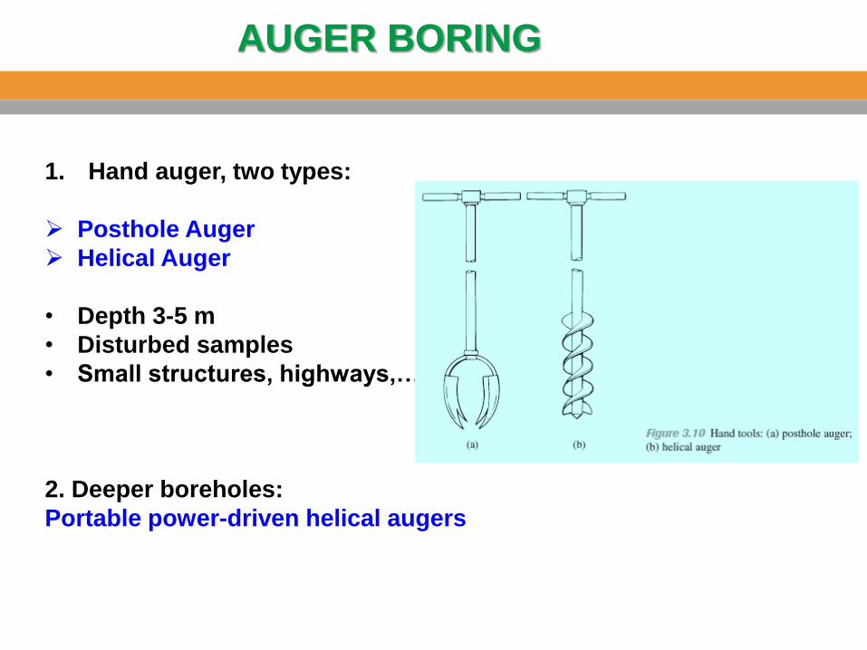
1. Hand auger, two types:
Posthole Auger
Helical Auger
• Depth 3-5 m
• Disturbed samples
• Small structures, highways,…
2. Deeper boreholes:
Portable power-driven helical augers
AUGER BORING
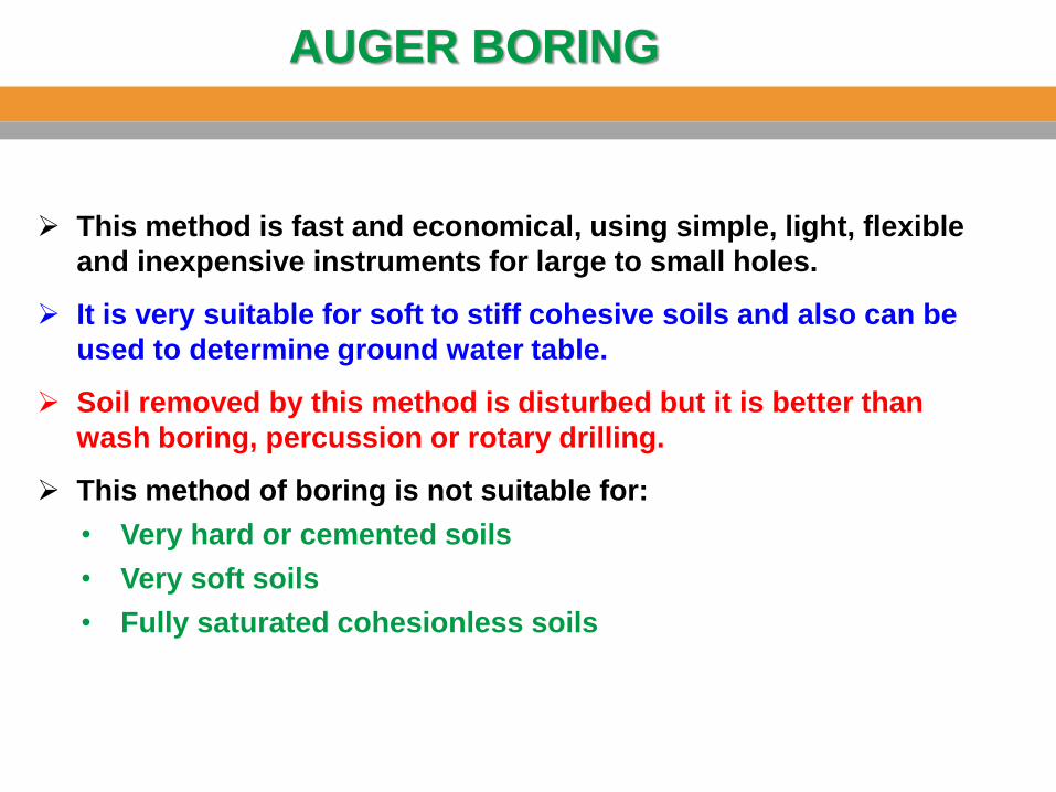
This method is fast and economical, using simple, light, flexible
and inexpensive instruments for large to small holes.
It is very suitable for soft to stiff cohesive soils and also can be
used to determine ground water table.
Soil removed by this method is disturbed but it is better than
wash boring, percussion or rotary drilling.
This method of boring is not suitable for:
• Very hard or cemented soils
• Very soft soils
• Fully saturated cohesionless soils
AUGER BORING
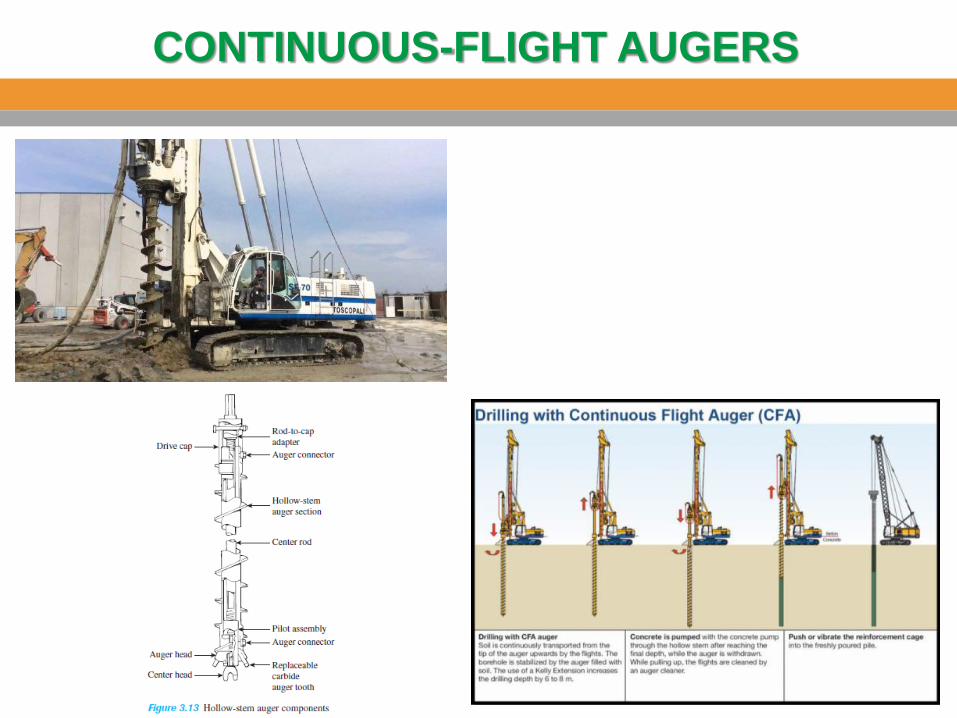
The sampling operation advances the borehole and the boring is
accomplished entirely by taking samples continuously.
Boreholes up to a depth of 60-70 m. They are available in sections of
about 1-2 m with either a solid or hollow stem with different
diameters.
Hollow-stem augers have a distinct advantage over solid-stem
augers in that they do not have to be removed frequently for
sampling or other tests.
The tip of the auger is attached to a cutter head.
The casing is used to prevent the caving in soils.
The flights of the augers bring the loose soil from the bottom of the
hole to the surface.
The driller can detect changes in the type of soil by noting changes
in the speed and sound of drilling.
CONTINUOUS-FLIGHT AUGERS
CONTINUOUS-FLIGHT AUGERS
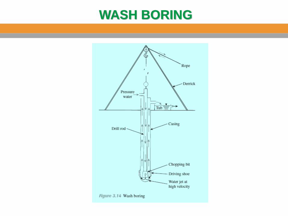
It is a popular method due to the use of limited equipment.
The advantage of this method is the use of inexpensive and easily
portable handling and drilling equipment.
First an open hole is formed on the ground so that the soil sampling
or rock drilling operation can be done below the hole.
The hole is advanced by chopping and twisting action of the light bit.
Cutting is done by forced water and water jet under pressure through
the rods operated inside the hole.
A pipe of 5 cm diameter is held vertically and filled with water using
horizontal lever arrangement and by the process of suction and
application of pressure, soil slurry comes out of the tube and pipe
goes down. This can be done up to a depth of 8m –10m.
Just by noting the change of color of soil coming out with the change
of soil character can be identified by any experienced person.
It gives completely disturbed sample and is not suitable for very soft
soil, fine to medium grained cohesionless soil and in cemented soil.
WASH BORING
WASH BORING
ROTARY DRILLING
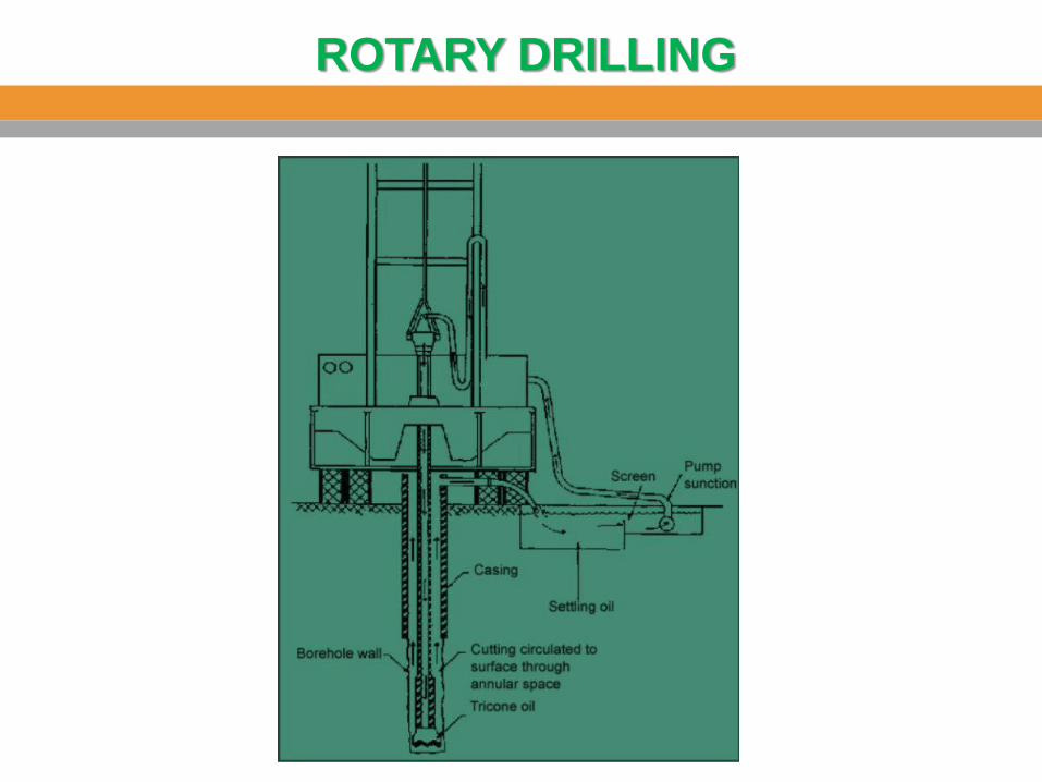
It is useful in case of highly resistant strata.
It is related to finding out the rock strata and also to access the quality of
rocks from cracks, fissures and joints. It can be used also in sands and silts.
The bore holes are advanced in depth by rotary method which is similar to
wash boring technique. A heavy string of the drill rod is used for choking
action.
The broken rock or soil fragments are removed by circulating water or drilling
mud pumped through the drill rods and bit up through the bore hole from
which it is collected in a settling tank for recirculation.
If the depth is small and the soil stable, water alone can be used. However,
drilling fluids are useful as they serve to stabilize the bore hole.
Drilling mud is slurry of bentonite in water. The drilling fluid causes stabilizing
effect to the bore hole partly due to higher specific gravity as compared with
water and partly due to formation of mud cake on the sides of the hole. As the
stabilizing effect is imparted by these drilling fluids no casing is required if
drilling fluid is used.
This method is suitable for boring holes of diameter 10 cm, or more preferably
15 to 20 cm in most of the rocks. It is uneconomical for holes less than 10 cm
diameter. The depth of various strata can be detected by inspection of
cuttings.
ROTARY DRILLING
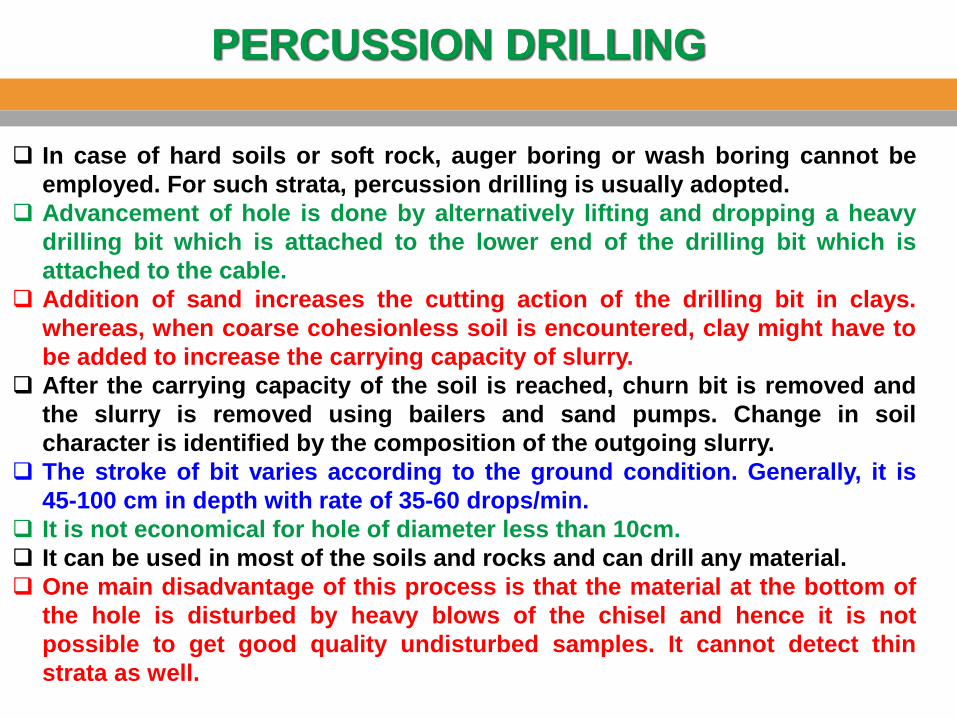
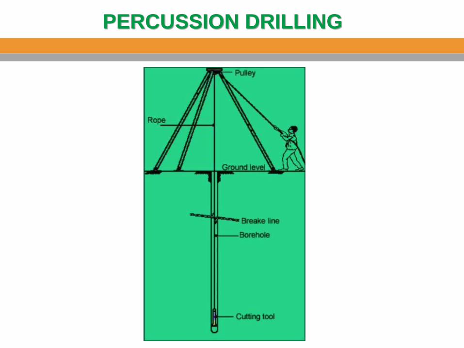
PERCUSSION DRILLINGPERCUSSION DRILLING
In case of hard soils or soft rock, auger boring or wash boring cannot be
employed. For such strata, percussion drilling is usually adopted.
Advancement of hole is done by alternatively lifting and dropping a heavy
drilling bit which is attached to the lower end of the drilling bit which is
attached to the cable.
Addition of sand increases the cutting action of the drilling bit in clays.
whereas, when coarse cohesionless soil is encountered, clay might have to
be added to increase the carrying capacity of slurry.
After the carrying capacity of the soil is reached, churn bit is removed and
the slurry is removed using bailers and sand pumps. Change in soil
character is identified by the composition of the outgoing slurry.
The stroke of bit varies according to the ground condition. Generally, it is
45-100 cm in depth with rate of 35-60 drops/min.
It is not economical for hole of diameter less than 10cm.
It can be used in most of the soils and rocks and can drill any material.
One main disadvantage of this process is that the material at the bottom of
the hole is disturbed by heavy blows of the chisel and hence it is not
possible to get good quality undisturbed samples. It cannot detect thin
strata as well.
PERCUSSION DRILLING
SOIL SAMPLING
Need for Soil Sampling
A satisfactory design of a foundation depends upon the accuracy
with which the various soil parameters required for the design
are obtained.
The accuracy of the soil parameters depends upon the accuracy
with which representative soil samples are obtained from the
field.
Sampling is carried out in order that soil and rock description,
and laboratory testing can be carried out.
Laboratory tests typically consist of:
Index tests (for example, specific gravity, water content)
Classification tests (for example, Atterberg’s limit tests on
clayey soil)
Tests to determine engineering design parameters (for
example strength, compressibility, and permeability).
SOIL SAMPLING
Factors to be considered while sampling soil
Samples should be representative of the ground from which they
are taken.
They should be large enough to contain representative particles
sizes, fabric, and fissuring and fracturing.
They should be taken in such a way that they have not lost
fractions of the in situ soil (for example, coarse or fine particles).
Where strength and compressibility tests are planned, they
should be subject to as little disturbance as possible.
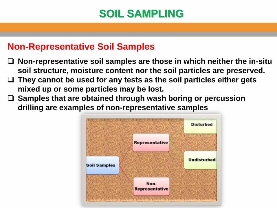
Non-Representative Soil Samples
Non-representative soil samples are those in which neither the in-situ
soil structure, moisture content nor the soil particles are preserved.
They cannot be used for any tests as the soil particles either gets
mixed up or some particles may be lost.
Samples that are obtained through wash boring or percussion
drilling are examples of non-representative samples
SOIL SAMPLING
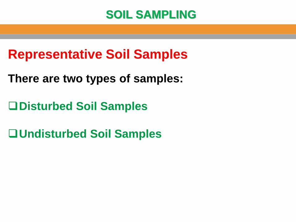
Representative Soil Samples
There are two types of samples:
Disturbed Soil Samples
Undisturbed Soil Samples
SOIL SAMPLING
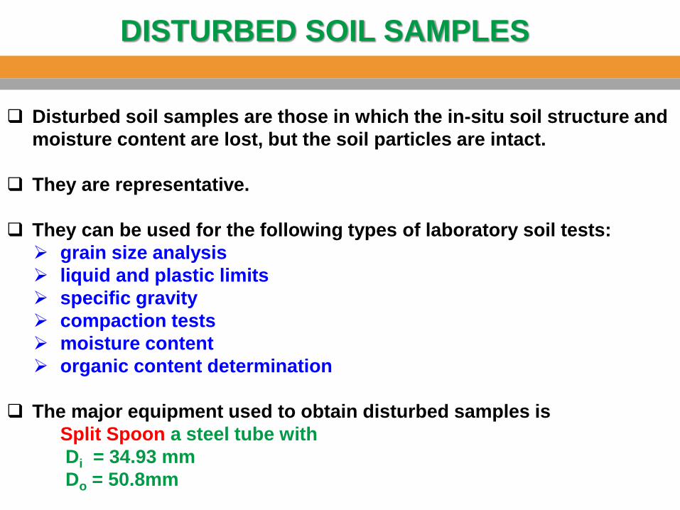
Disturbed soil samples are those in which the in-situ soil structure and
moisture content are lost, but the soil particles are intact.
They are representative.
They can be used for the following types of laboratory soil tests:
grain size analysis
liquid and plastic limits
specific gravity
compaction tests
moisture content
organic content determination
The major equipment used to obtain disturbed samples is
Split Spoon a steel tube with
Di = 34.93 mm
Do = 50.8mm
DISTURBED SOIL SAMPLES
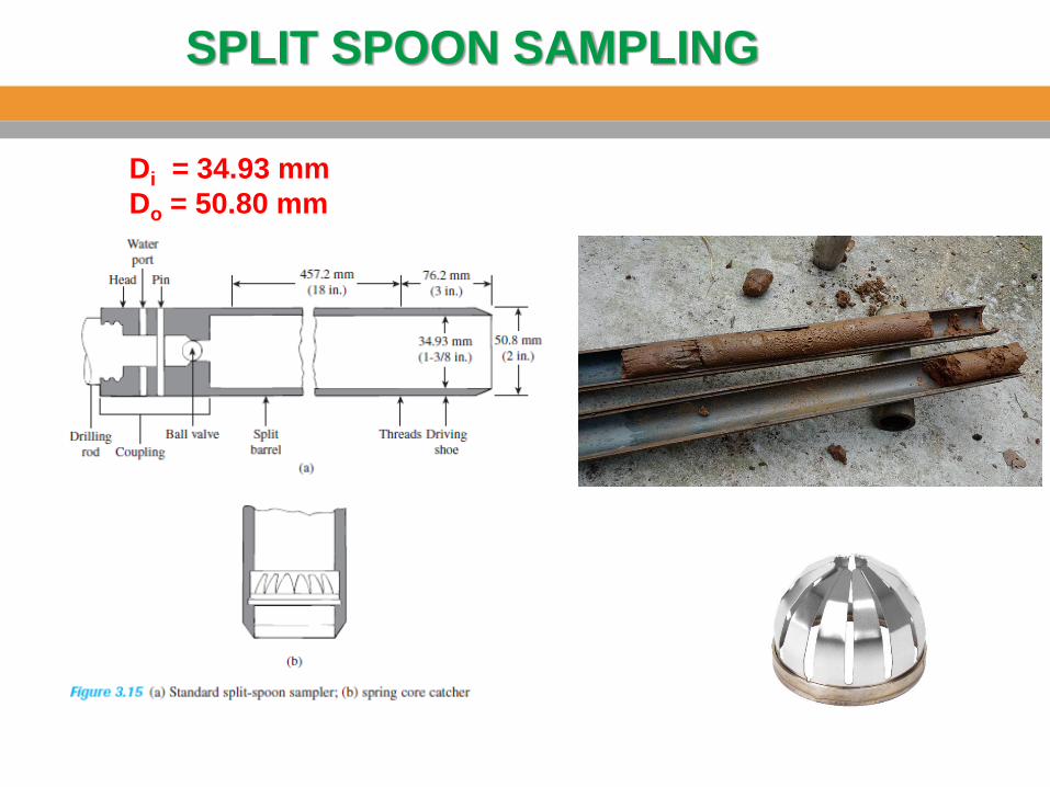
Di = 34.93 mm
Do = 50.80 mm
SPLIT SPOON SAMPLING
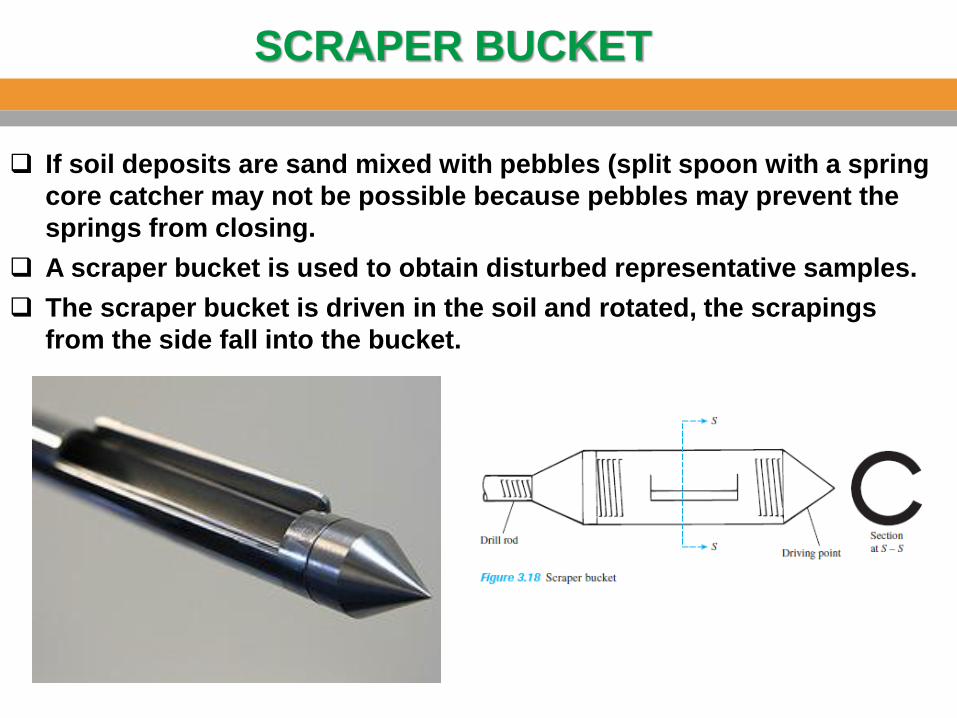
SCRAPER BUCKET
If soil deposits are sand mixed with pebbles (split spoon with a spring
core catcher may not be possible because pebbles may prevent the
springs from closing.
A scraper bucket is used to obtain disturbed representative samples.
The scraper bucket is driven in the soil and rotated, the scrapings
from the side fall into the bucket.
Undisturbed soil samples are those in which the in-situ soil structure
and moisture content are preserved.
They are representative and also intact.
These are used for the following types of laboratory soil tests:
Consolidation tests.
Hydraulic Conductivity tests.
Shear Strength tests.
These samples are more complex and expensive, and they are
suitable for clays, however in sand, it is very difficult to obtain
undisturbed samples.
The major equipment used to obtain undisturbed sample is Shelby
tube (thin-walled tube) and piston sampler.
UNDISTURBED SOIL SAMPLES
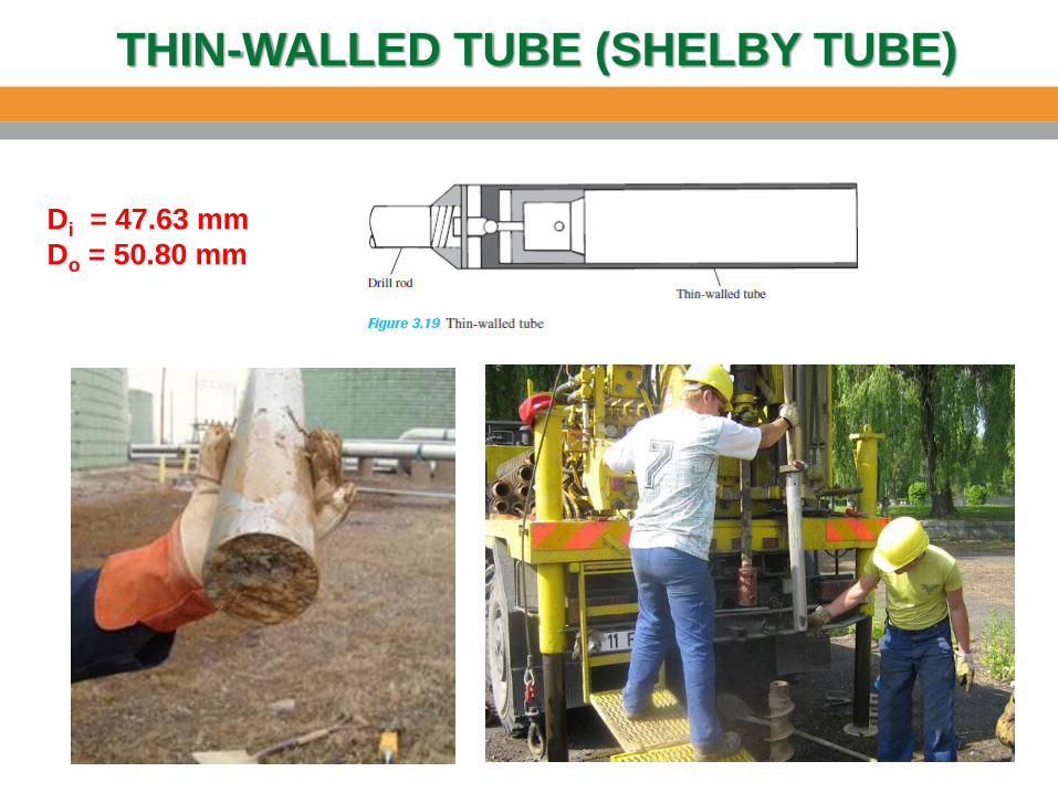
THIN-WALLED TUBE (SHELBY TUBE)
Di = 47.63 mm
Do = 50.80 mm
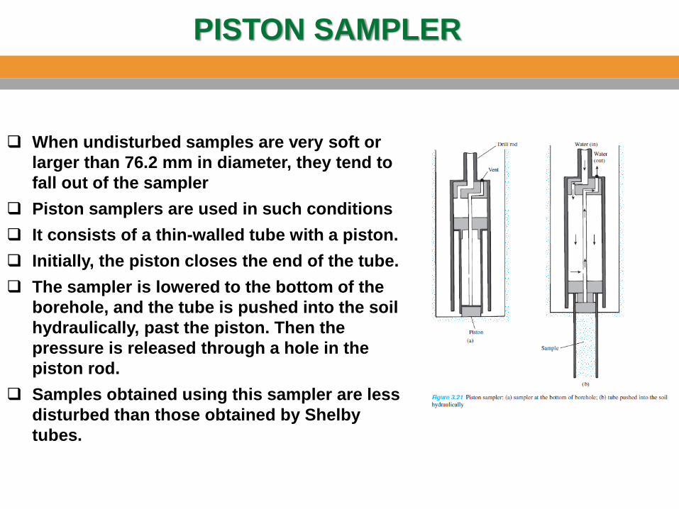
PISTON SAMPLER
When undisturbed samples are very soft or
larger than 76.2 mm in diameter, they tend to
fall out of the sampler
Piston samplers are used in such conditions
It consists of a thin-walled tube with a piston.
Initially, the piston closes the end of the tube.
The sampler is lowered to the bottom of the
borehole, and the tube is pushed into the soil
hydraulically, past the piston. Then the
pressure is released through a hole in the
piston rod.
Samples obtained using this sampler are less
disturbed than those obtained by Shelby
tubes.
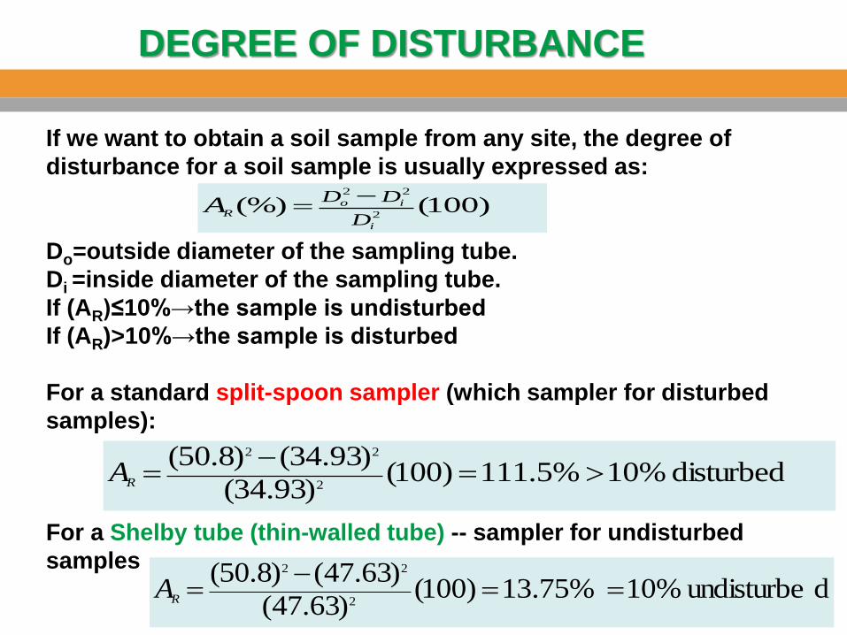
DEGREE OF DISTURBANCE
If we want to obtain a soil sample from any site, the degree of
disturbance for a soil sample is usually expressed as:
Do=outside diameter of the sampling tube.
Di =inside diameter of the sampling tube.
If (AR)≤10%→the sample is undisturbed
If (AR)>10%→the sample is disturbed
For a standard split-spoon sampler (which sampler for disturbed
samples):
100)((%)2
22
i
ioR
D
DDA
disturbed 10% 111.5% 100)()93.34(
)93.34()8.50(2
22
RA
For a Shelby tube (thin-walled tube) -- sampler for undisturbed
samples
dundisturbe 10% 13.75% 100)()63.47(
)63.47()8.50(2
22
RA
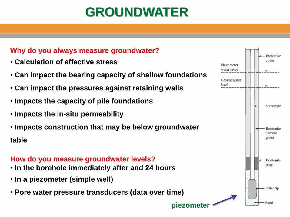
GROUNDWATER
Why do you always measure groundwater?
• Calculation of effective stress
• Can impact the bearing capacity of shallow foundations
• Can impact the pressures against retaining walls
• Impacts the capacity of pile foundations
• Impacts the in-situ permeability
• Impacts construction that may be below groundwater
table
How do you measure groundwater levels?
• In the borehole immediately after and 24 hours
• In a piezometer (simple well)
• Pore water pressure transducers (data over time)
piezometer
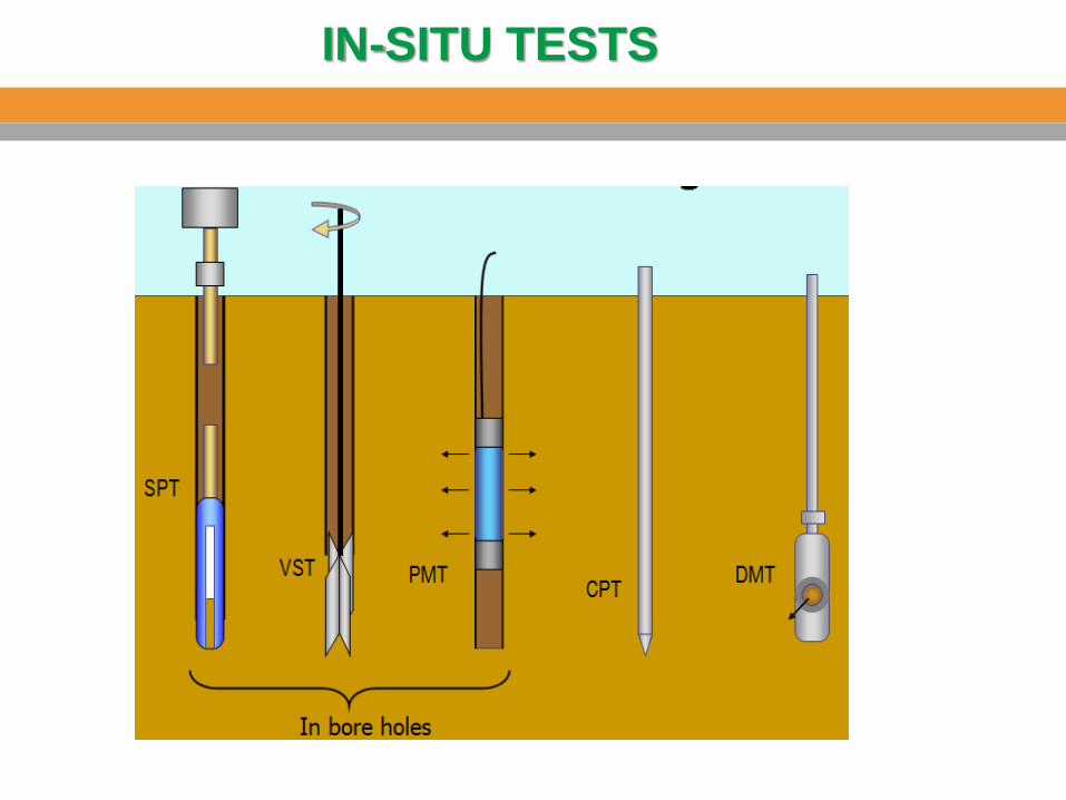
IN-SITU TESTS
The ground is tested in-place by instruments that are inserted in
or penetrate the ground.
In-situ tests are normally associated with tests for which a
borehole either is unnecessary or is only an incidental part of the
overall test procedure, required only to permit insertion of the
testing tool or equipment.
Improvements in apparatus, instrumentation, and technique of
deployment, data acquisition and analysis procedure have been
significant.
Advantages
Tests are carried out in place in the natural environment without
sampling disturbance, which can cause detrimental effects and
modifications to stresses, strains, drainage, fabric and particle
arrangement.
Continuous profiles of stratigraphy and engineering properties/
characteristics can be obtained.
Detection of planes of weakness and defects are more likely and
practical.
Methods are usually fast, repeatable, produce large amounts of
information and are cost effective.
Tests can be carried out in soils that are either impossible or difficult
to sample without the use of expensive specialized methods.
A large volume of soil may be tested than is normally practicable for
laboratory testing. This may be more representative of the soil mass.
IN-SITU TESTS
Disadvantages
Samples are not obtained; the soil tested cannot be positively
identified. The exception to this is the SPT in which a sample,
although disturbed, is obtained.
The fundamental behavior of soils during testing is not well
understood.
Drainage conditions during testing are not known.
Consistent, rational interpretation is often difficult and uncertain.
The stress path imposed during testing may bear no resemblance to
the stress path induced by full-scale engineering structure.
Most push-in devices are not suitable for a wide range of ground
conditions.
Some disturbance is imparted to the ground by the insertion or
installation of the instrument.
There is usually no direct measurement of engineering properties.
Empirical correlations usually have to be applied to interpret and
obtain engineering properties and designs
IN-SITU TESTS
IN-SITU TESTS
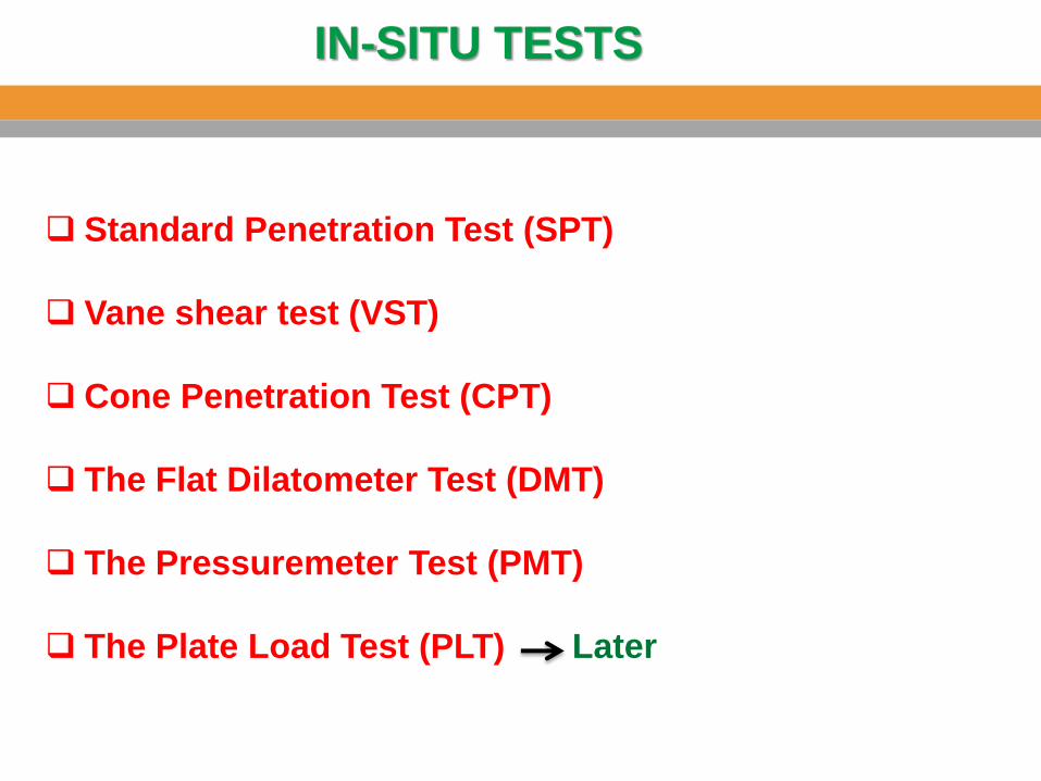
Standard Penetration Test (SPT)
Vane shear test (VST)
Cone Penetration Test (CPT)
The Flat Dilatometer Test (DMT)
The Pressuremeter Test (PMT)
The Plate Load Test (PLT) Later
IN-SITU TESTS
This test is one of the most important soil tests for geotechnical engineers
because it’s widely used in calculating different factors.
It is used as an indicator of relative density and stiffness of granular soils as
well as an indicator of consistency in a wide range of other ground.
Methods have been developed to apply SPT results to a wide range of
geotechnical applications including shallow and deep foundations.
The main standard for the SPT is the American Society for Testing and
Materials (ASTM D-1586-99).
Aim: To perform standard penetration to obtain the penetration resistance
(N-value) along the depth at a given site.
Advantages of SPT:
• Simple and rugged
• Low cost
• Obtain a sample
• Can be performed in most soil types
Disadvantages of SPT:
• Disturbed sample (index tests only)
• Crude number (N value)
• Not applicable in soft clays and silts
• High variability and uncertainty.
STANDARD PENETRATION TEST (SPT)
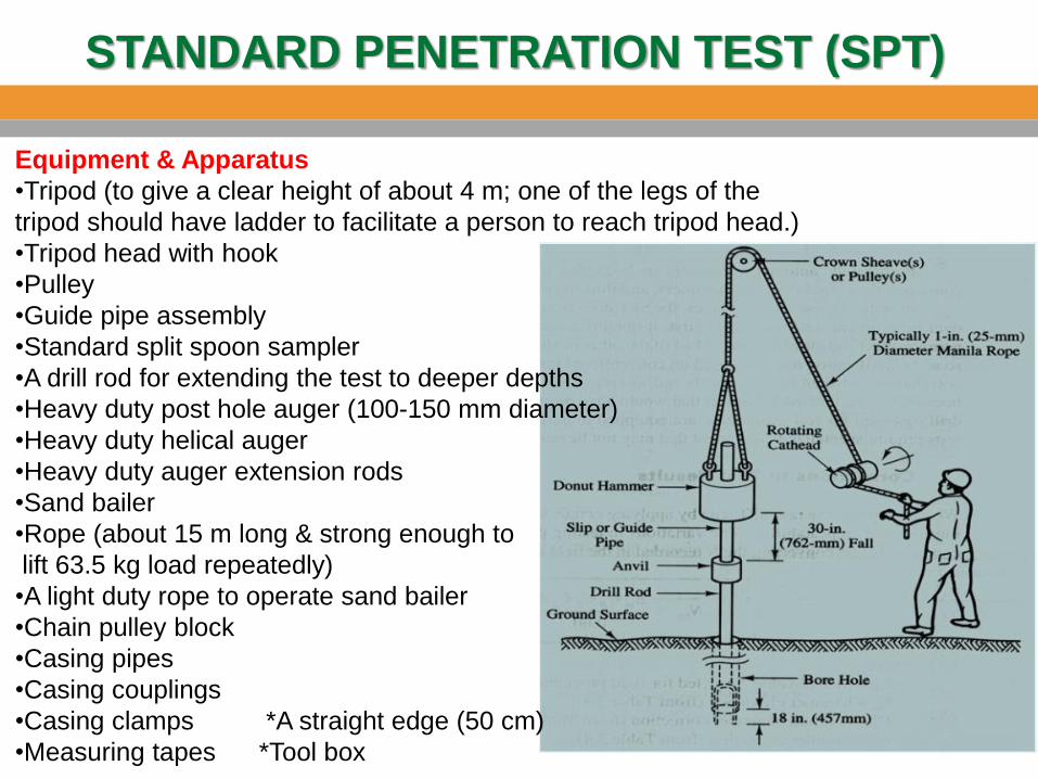
Equipment & Apparatus
•Tripod (to give a clear height of about 4 m; one of the legs of the
tripod should have ladder to facilitate a person to reach tripod head.)
•Tripod head with hook
•Pulley
•Guide pipe assembly
•Standard split spoon sampler
•A drill rod for extending the test to deeper depths
•Heavy duty post hole auger (100-150 mm diameter)
•Heavy duty helical auger
•Heavy duty auger extension rods
•Sand bailer
•Rope (about 15 m long & strong enough to
lift 63.5 kg load repeatedly)
•A light duty rope to operate sand bailer
•Chain pulley block
•Casing pipes
•Casing couplings
•Casing clamps *A straight edge (50 cm)
•Measuring tapes *Tool box
STANDARD PENETRATION TEST (SPT)
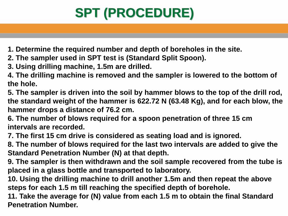
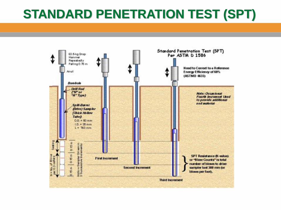
SPT (PROCEDURE)
1. Determine the required number and depth of boreholes in the site.
2. The sampler used in SPT test is (Standard Split Spoon).
3. Using drilling machine, 1.5m are drilled.
4. The drilling machine is removed and the sampler is lowered to the bottom of
the hole.
5. The sampler is driven into the soil by hammer blows to the top of the drill rod,
the standard weight of the hammer is 622.72 N (63.48 Kg), and for each blow, the
hammer drops a distance of 76.2 cm.
6. The number of blows required for a spoon penetration of three 15 cm
intervals are recorded.
7. The first 15 cm drive is considered as seating load and is ignored.
8. The number of blows required for the last two intervals are added to give the
Standard Penetration Number (N) at that depth.
9. The sampler is then withdrawn and the soil sample recovered from the tube is
placed in a glass bottle and transported to laboratory.
10. Using the drilling machine to drill another 1.5m and then repeat the above
steps for each 1.5 m till reaching the specified depth of borehole.
11. Take the average for (N) value from each 1.5 m to obtain the final Standard
Penetration Number.
STANDARD PENETRATION TEST (SPT)
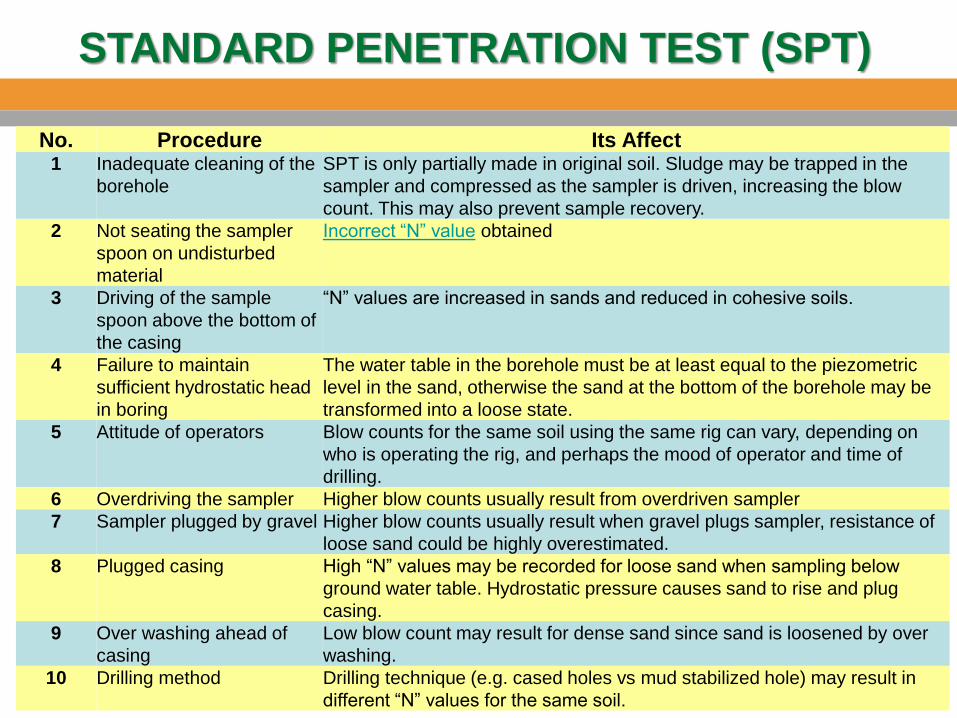
No. Procedure Its Affect1 Inadequate cleaning of the
borehole
SPT is only partially made in original soil. Sludge may be trapped in the
sampler and compressed as the sampler is driven, increasing the blow
count. This may also prevent sample recovery.
2 Not seating the sampler
spoon on undisturbed
material
Incorrect “N” value obtained
3 Driving of the sample
spoon above the bottom of
the casing
“N” values are increased in sands and reduced in cohesive soils.
4 Failure to maintain
sufficient hydrostatic head
in boring
The water table in the borehole must be at least equal to the piezometric
level in the sand, otherwise the sand at the bottom of the borehole may be
transformed into a loose state.
5 Attitude of operators Blow counts for the same soil using the same rig can vary, depending on
who is operating the rig, and perhaps the mood of operator and time of
drilling.
6 Overdriving the sampler Higher blow counts usually result from overdriven sampler
7 Sampler plugged by gravel Higher blow counts usually result when gravel plugs sampler, resistance of
loose sand could be highly overestimated.
8 Plugged casing High “N” values may be recorded for loose sand when sampling below
ground water table. Hydrostatic pressure causes sand to rise and plug
casing.
9 Over washing ahead of
casing
Low blow count may result for dense sand since sand is loosened by over
washing.
10 Drilling method Drilling technique (e.g. cased holes vs mud stabilized hole) may result in
different “N” values for the same soil.
STANDARD PENETRATION TEST (SPT)
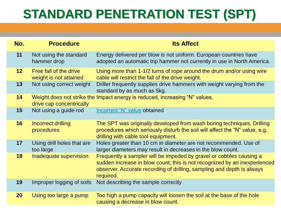
No. Procedure Its Affect
11 Not using the standard
hammer drop
Energy delivered per blow is not uniform. European countries have
adopted an automatic trip hammer not currently in use in North America.
12 Free fall of the drive
weight is not attained
Using more than 1-1/2 turns of rope around the drum and/or using wire
cable will restrict the fall of the drive weight.
13 Not using correct weight Driller frequently supplies drive hammers with weight varying from the
standard by as much as 5kg.
14 Weight does not strike the
drive cap concentrically
Impact energy is reduced, increasing “N” values.
15 Not using a guide rod Incorrect “N” value obtained
16 Incorrect drilling
procedures
The SPT was originally developed from wash boring techniques. Drilling
procedures which seriously disturb the soil will affect the “N” value, e.g.
drilling with cable tool equipment.
17 Using drill holes that are
too large
Holes greater than 10 cm in diameter are not recommended. Use of
larger diameters may result in decreases in the blow count.
18 Inadequate supervision Frequently a sampler will be impeded by gravel or cobbles causing a
sudden increase in blow count; this is not recognized by an inexperienced
observer. Accurate recording of drilling, sampling and depth is always
required.
19 Improper logging of soils Not describing the sample correctly
20 Using too large a pump Too high a pump capacity will loosen the soil at the base of the hole
causing a decrease in blow count.
STANDARD PENETRATION TEST (SPT)
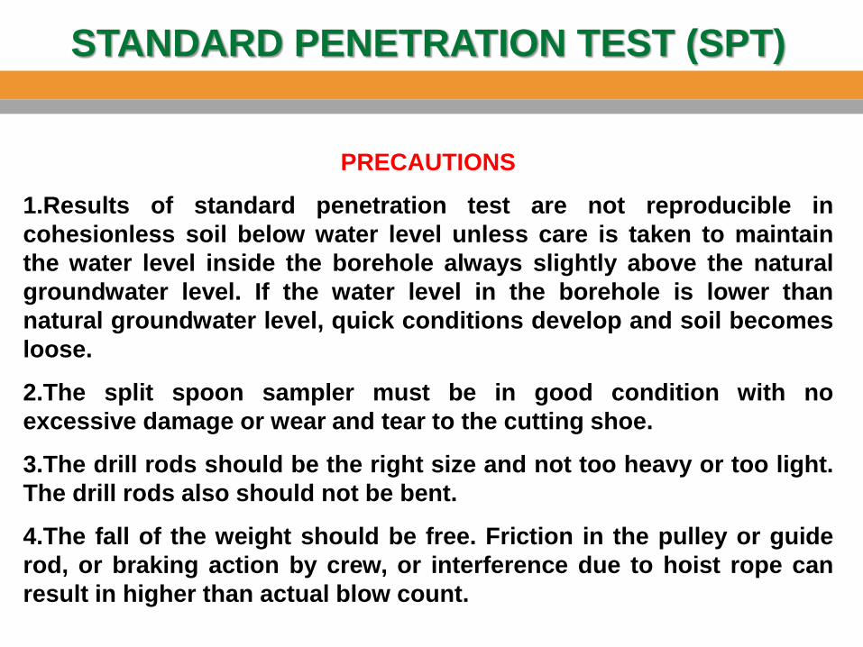
PRECAUTIONS
1.Results of standard penetration test are not reproducible in
cohesionless soil below water level unless care is taken to maintain
the water level inside the borehole always slightly above the natural
groundwater level. If the water level in the borehole is lower than
natural groundwater level, quick conditions develop and soil becomes
loose.
2.The split spoon sampler must be in good condition with no
excessive damage or wear and tear to the cutting shoe.
3.The drill rods should be the right size and not too heavy or too light.
The drill rods also should not be bent.
4.The fall of the weight should be free. Friction in the pulley or guide
rod, or braking action by crew, or interference due to hoist rope can
result in higher than actual blow count.
STANDARD PENETRATION TEST (SPT)
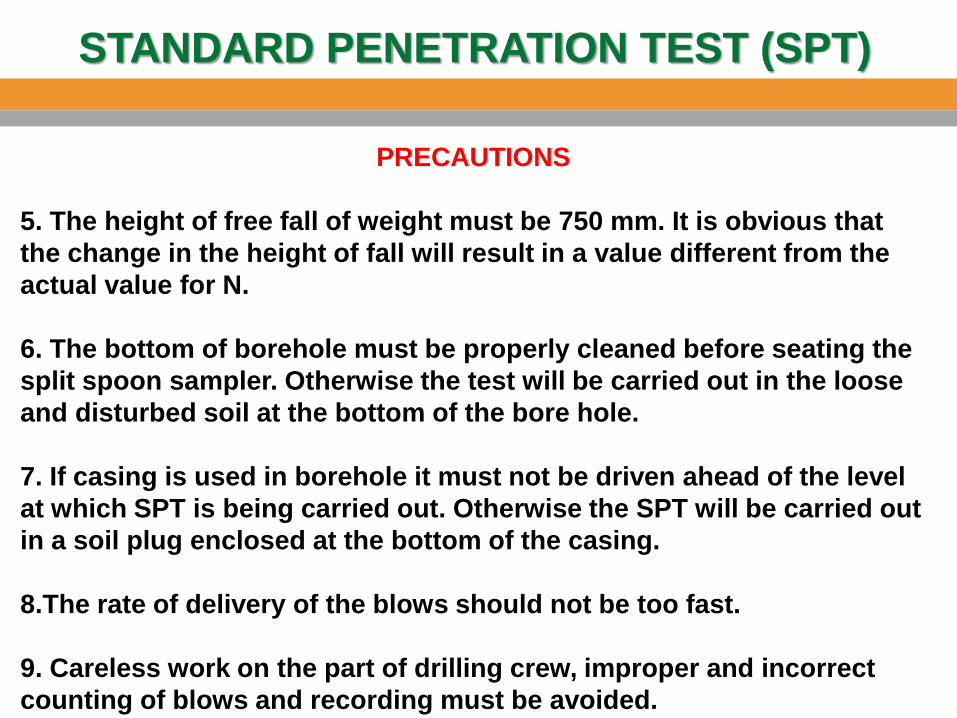
PRECAUTIONS
5. The height of free fall of weight must be 750 mm. It is obvious that
the change in the height of fall will result in a value different from the
actual value for N.
6. The bottom of borehole must be properly cleaned before seating the
split spoon sampler. Otherwise the test will be carried out in the loose
and disturbed soil at the bottom of the bore hole.
7. If casing is used in borehole it must not be driven ahead of the level
at which SPT is being carried out. Otherwise the SPT will be carried out
in a soil plug enclosed at the bottom of the casing.
8.The rate of delivery of the blows should not be too fast.
9. Careless work on the part of drilling crew, improper and incorrect
counting of blows and recording must be avoided.
STANDARD PENETRATION TEST (SPT)
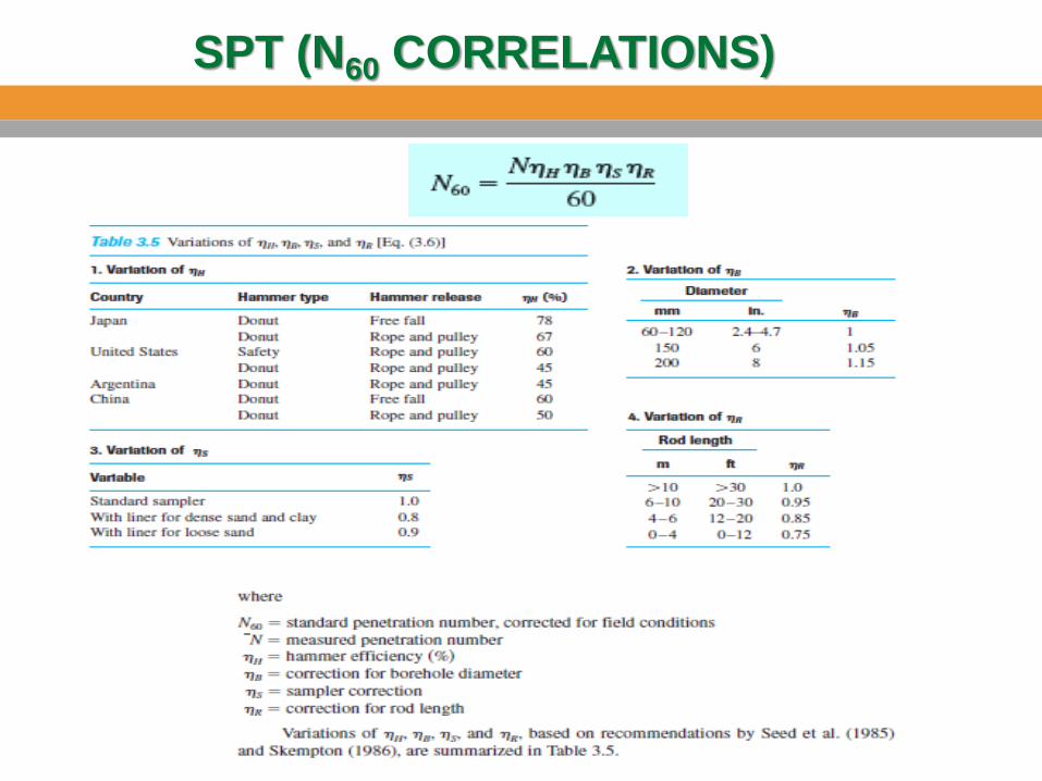
SPT (CORRECTION TO N VALUE)
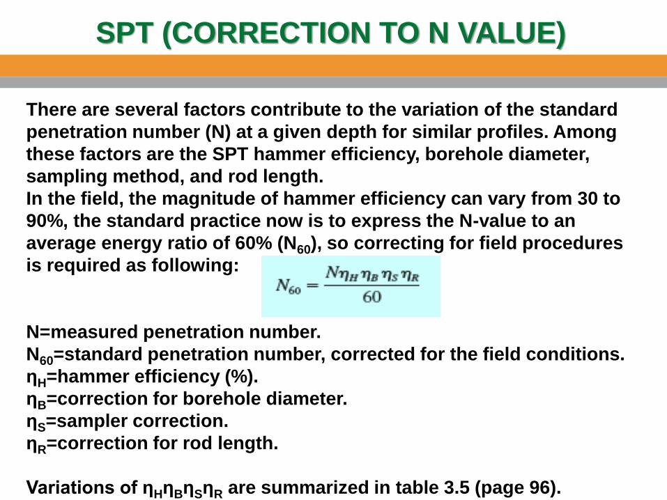
There are several factors contribute to the variation of the standard
penetration number (N) at a given depth for similar profiles. Among
these factors are the SPT hammer efficiency, borehole diameter,
sampling method, and rod length.
In the field, the magnitude of hammer efficiency can vary from 30 to
90%, the standard practice now is to express the N-value to an
average energy ratio of 60% (N60), so correcting for field procedures
is required as following:
N=measured penetration number.
N60=standard penetration number, corrected for the field conditions.
ηH=hammer efficiency (%).
ηB=correction for borehole diameter.
ηS=sampler correction.
ηR=correction for rod length.
Variations of ηHηBηSηR are summarized in table 3.5 (page 96).
SPT (N60 CORRELATIONS)
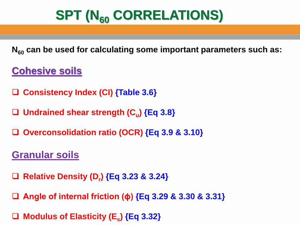
SPT (N60 CORRELATIONS)
N60 can be used for calculating some important parameters such as:
Cohesive soils
Consistency Index (CI) {Table 3.6}
Undrained shear strength (Cu) {Eq 3.8}
Overconsolidation ratio (OCR) {Eq 3.9 & 3.10}
Granular soils
Relative Density (Dr) {Eq 3.23 & 3.24}
Angle of internal friction (ϕ) {Eq 3.29 & 3.30 & 3.31}
Modulus of Elasticity (Es) {Eq 3.32}
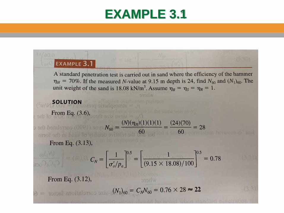
EXAMPLE 3.1
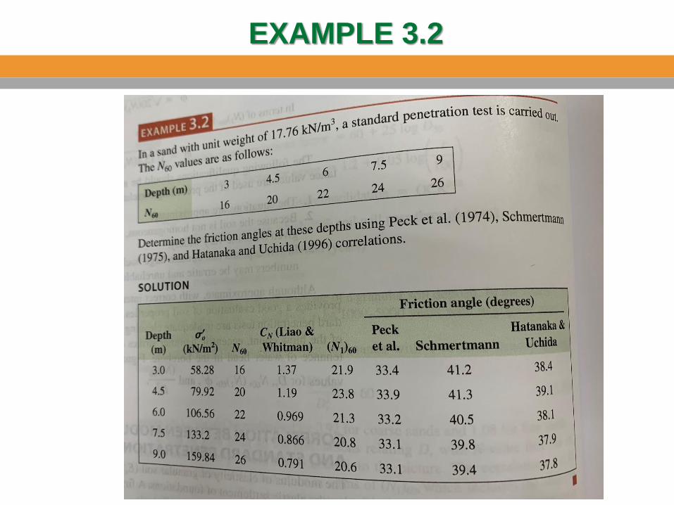
EXAMPLE 3.2
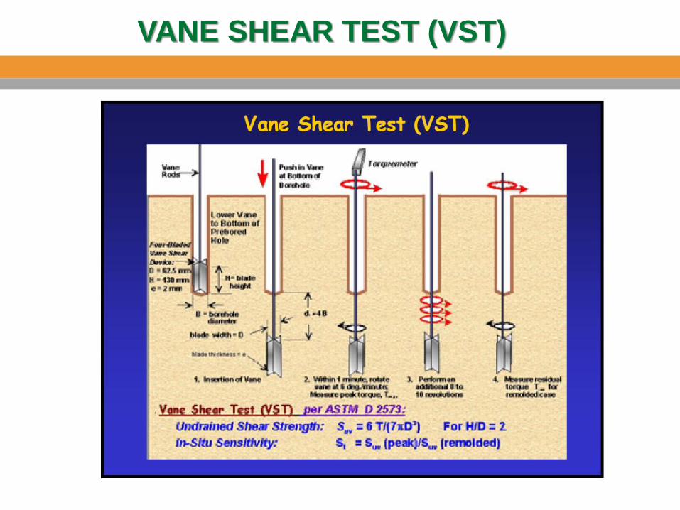
Vane shear test is used to evaluate the in-situ undrained shear
strength (cu) of soft to stiff clays and silts. Both peak and remolded
strengths can be measured and their ratio is termed soil sensitivity.
Advantages of VST:
• Simple test and equipment
• Long history of use in practice
Disadvantages of VST:
• Limited application to soft to stiff clays and silts
• Slow and time-consuming
• Raw cu values need (empirical) correction
VANE SHEAR TEST (VST)
VANE SHEAR TEST (VST)
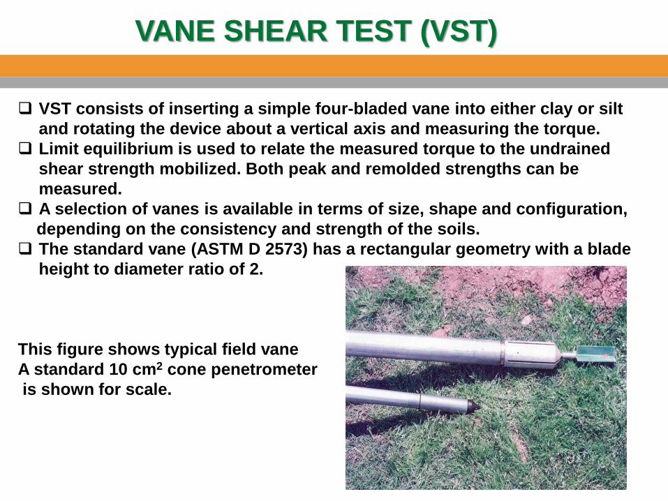
VST consists of inserting a simple four-bladed vane into either clay or silt
and rotating the device about a vertical axis and measuring the torque.
Limit equilibrium is used to relate the measured torque to the undrained
shear strength mobilized. Both peak and remolded strengths can be
measured.
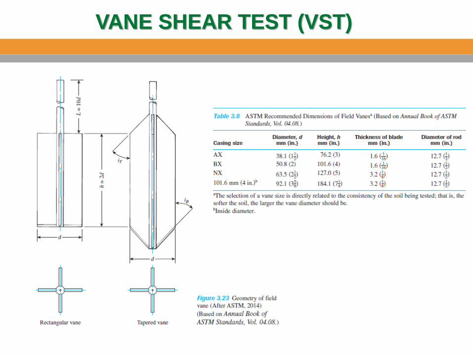
A selection of vanes is available in terms of size, shape and configuration,
depending on the consistency and strength of the soils.
The standard vane (ASTM D 2573) has a rectangular geometry with a blade
height to diameter ratio of 2.
This figure shows typical field vane
A standard 10 cm2 cone penetrometer
is shown for scale.
VANE SHEAR TEST (VST)
Test Procedure
Test procedures are outlined in ASTM D 2573.
The test is often carried out by pushing the vane into the soil from the
bottom of a borehole and the vane should be pushed at least four borehole
diameters below the base of the borehole to avoid disturbance from drilling.
The test can also be carried out using direct-push equipment pushing from
the ground surface when there are no hard layers.
Within 5 minutes after insertion, rotation should be carried out at a constant
rate of 6 degrees per minute (0.1o/s) with frequent measurements of the
mobilized torque.
Depending on the type of equipment used, there is the potential for friction
to develop along the push rods. This friction needs to be either minimized or
accounted for in the measurements.
VANE SHEAR TEST (VST)
VANE SHEAR TEST (VST)
VANE SHEAR TEST (VST)
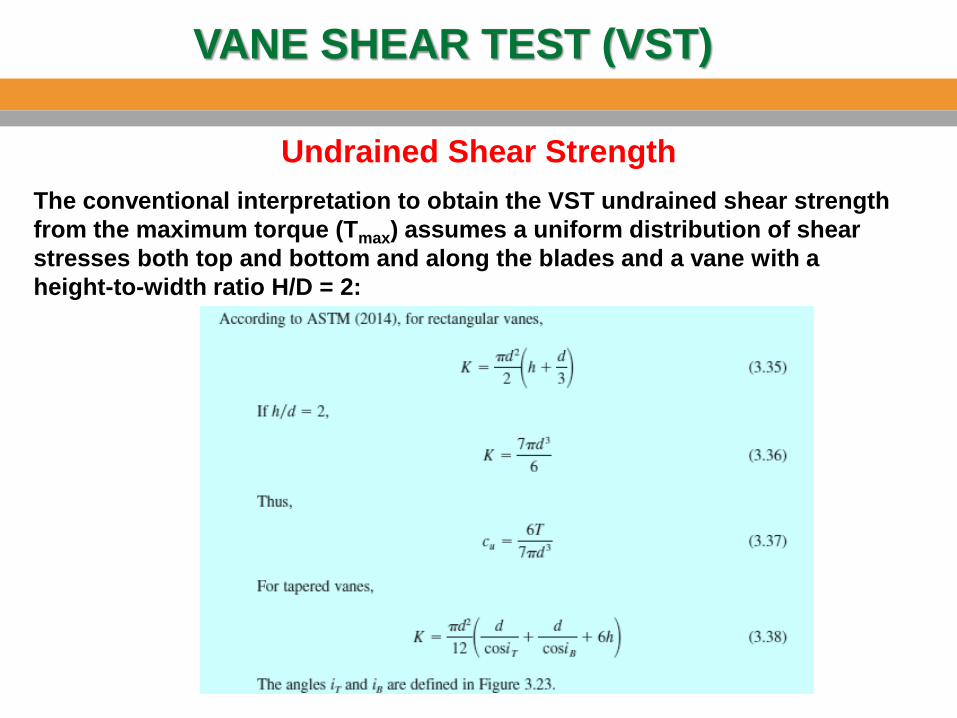
Undrained Shear Strength
The conventional interpretation to obtain the VST undrained shear strength
from the maximum torque (Tmax) assumes a uniform distribution of shear
stresses both top and bottom and along the blades and a vane with a
height-to-width ratio H/D = 2:
VANE SHEAR TEST (VST)
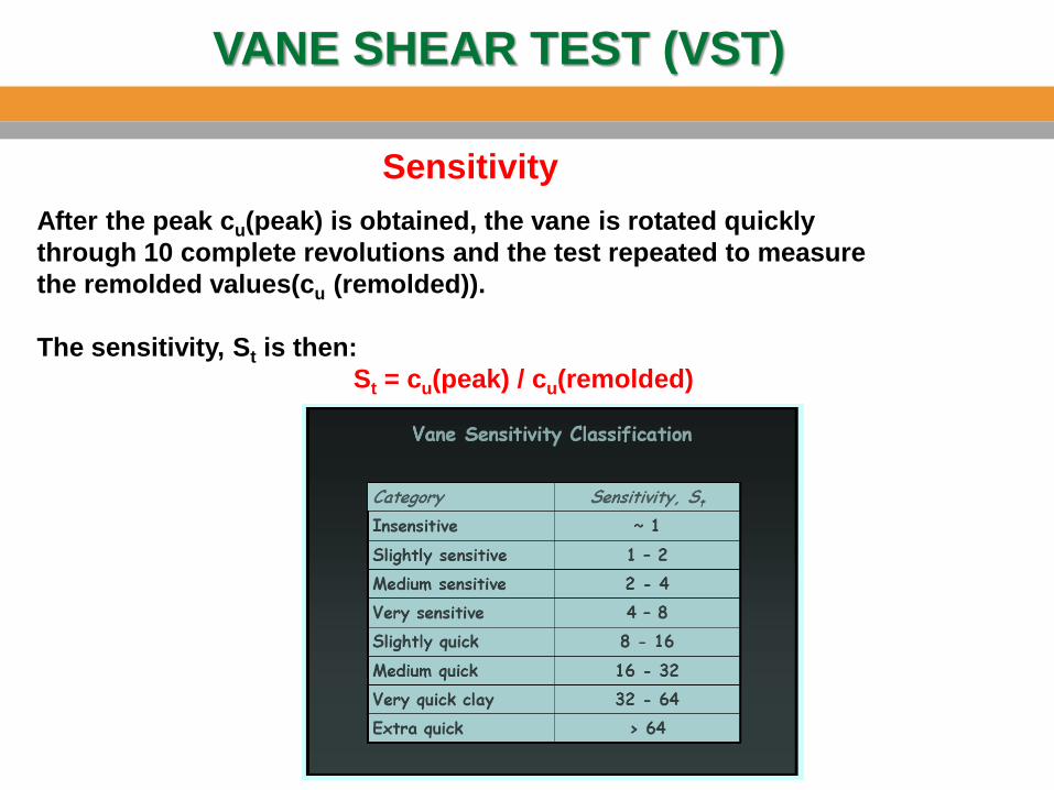
Sensitivity
After the peak cu(peak) is obtained, the vane is rotated quickly
through 10 complete revolutions and the test repeated to measure
the remolded values(cu (remolded)).
The sensitivity, St is then:
St = cu(peak) / cu(remolded)
VANE SHEAR TEST (VST)
Vane Correction Factor
Since there is no unique value for the undrained shear strength of fine
grained soils, it is common that the VST strength is corrected prior to
application in stability analyses involving embankments on soft ground,
bearing capacity and excavations in soft ground.
Cu(corrected) = l Cu(VST)
Where l is an empirical correction factor that has been related to plasticity
index (PI) and void ratio.
Correlation between cu and Preconsolidation pressure and overconsolidation
ratio.
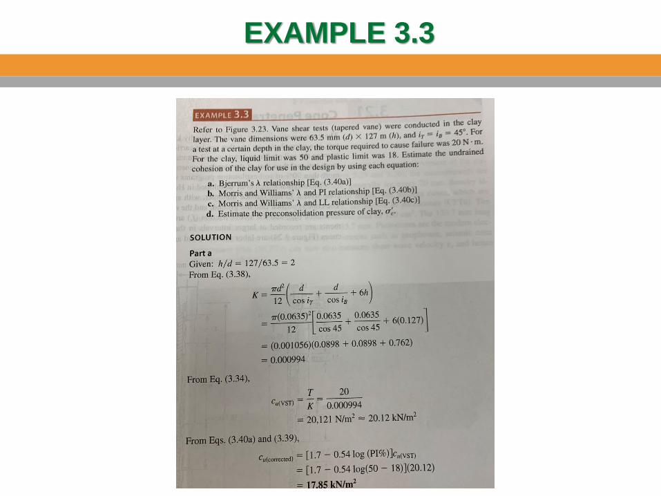
EXAMPLE 3.3
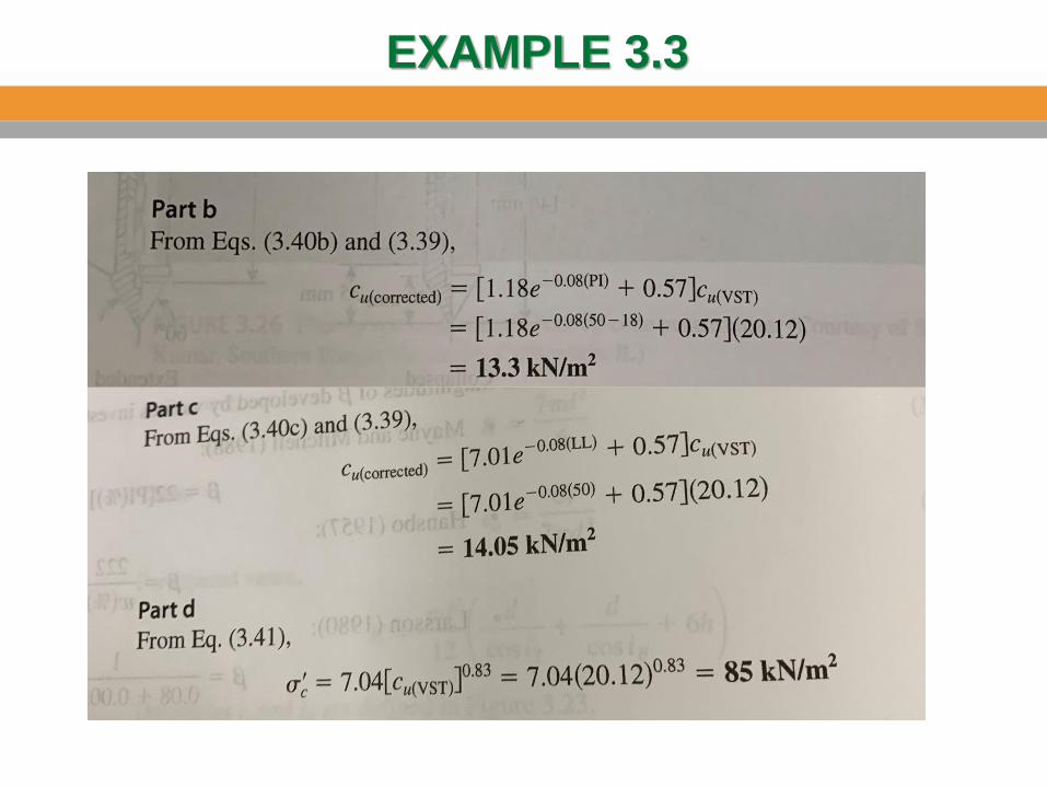
EXAMPLE 3.3
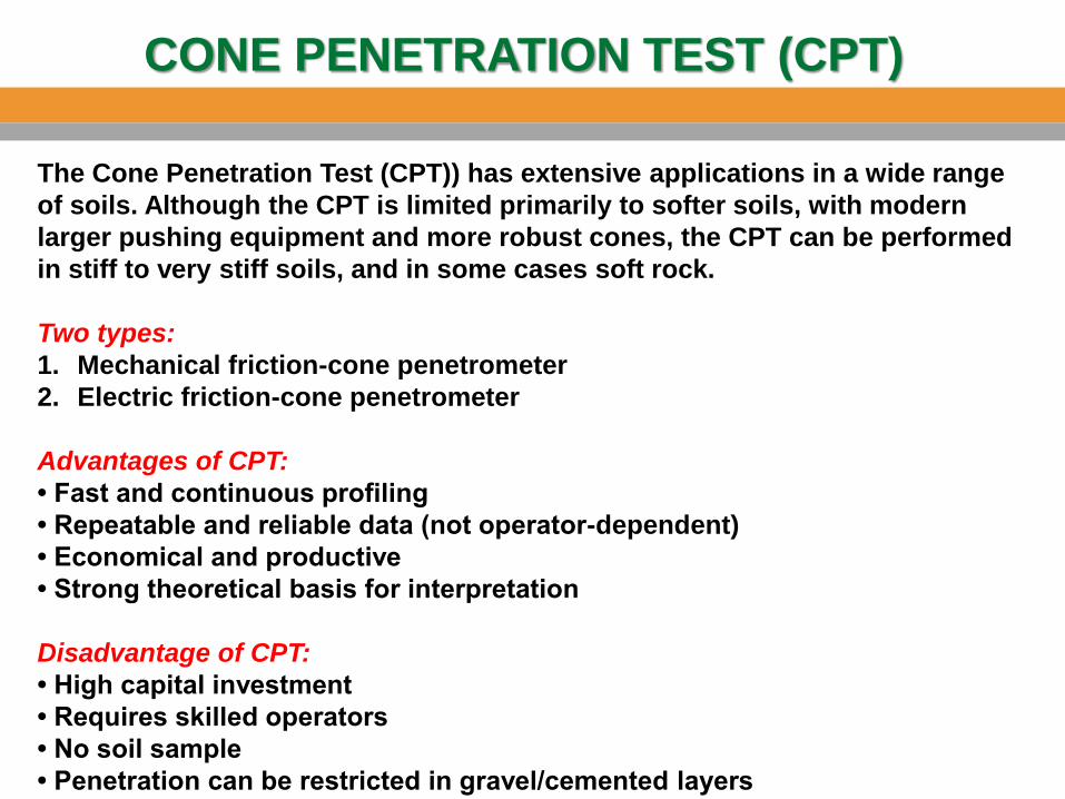
The Cone Penetration Test (CPT)) has extensive applications in a wide range
of soils. Although the CPT is limited primarily to softer soils, with modern
larger pushing equipment and more robust cones, the CPT can be performed
in stiff to very stiff soils, and in some cases soft rock.
Two types:
1. Mechanical friction-cone penetrometer
2. Electric friction-cone penetrometer
Advantages of CPT:
• Fast and continuous profiling
• Repeatable and reliable data (not operator-dependent)
• Economical and productive
• Strong theoretical basis for interpretation
Disadvantage of CPT:
• High capital investment
• Requires skilled operators
• No soil sample
• Penetration can be restricted in gravel/cemented layers
CONE PENETRATION TEST (CPT)
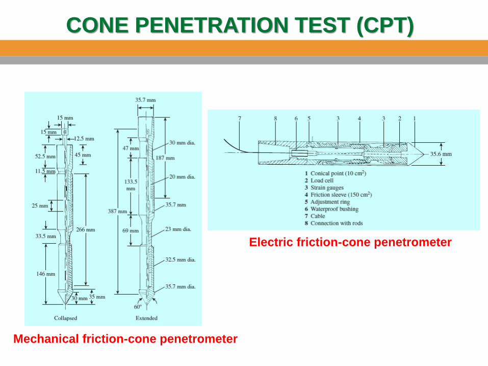
CONE PENETRATION TEST (CPT)
Mechanical friction-cone penetrometer
Electric friction-cone penetrometer
CONE PENETRATION TEST (CPT)
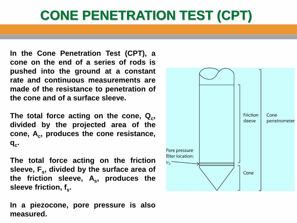
In the Cone Penetration Test (CPT), a
cone on the end of a series of rods is
pushed into the ground at a constant
rate and continuous measurements are
made of the resistance to penetration of
the cone and of a surface sleeve.
The total force acting on the cone, Qc,
divided by the projected area of the
cone, Ac, produces the cone resistance,
qc.
The total force acting on the friction
sleeve, Fs, divided by the surface area of
the friction sleeve, As, produces the
sleeve friction, fs.
In a piezocone, pore pressure is also
measured.
CONE PENETRATION TEST (CPT)
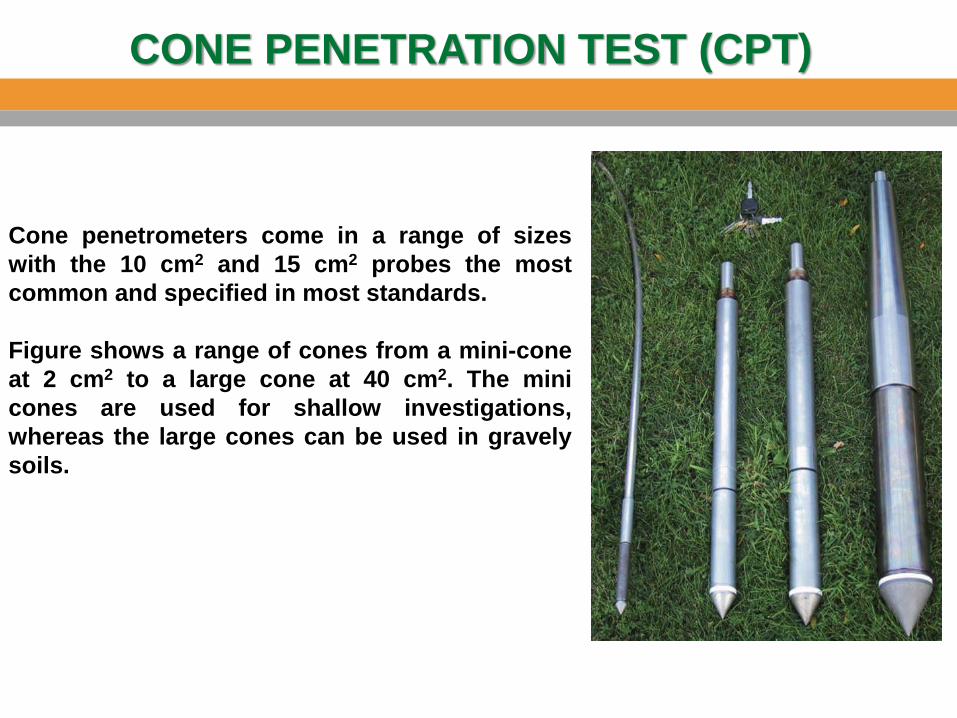
Cone penetrometers come in a range of sizes
with the 10 cm2 and 15 cm2 probes the most
common and specified in most standards.
Figure shows a range of cones from a mini-cone
at 2 cm2 to a large cone at 40 cm2. The mini
cones are used for shallow investigations,
whereas the large cones can be used in gravely
soils.
CONE PENETRATION TEST (CPT)
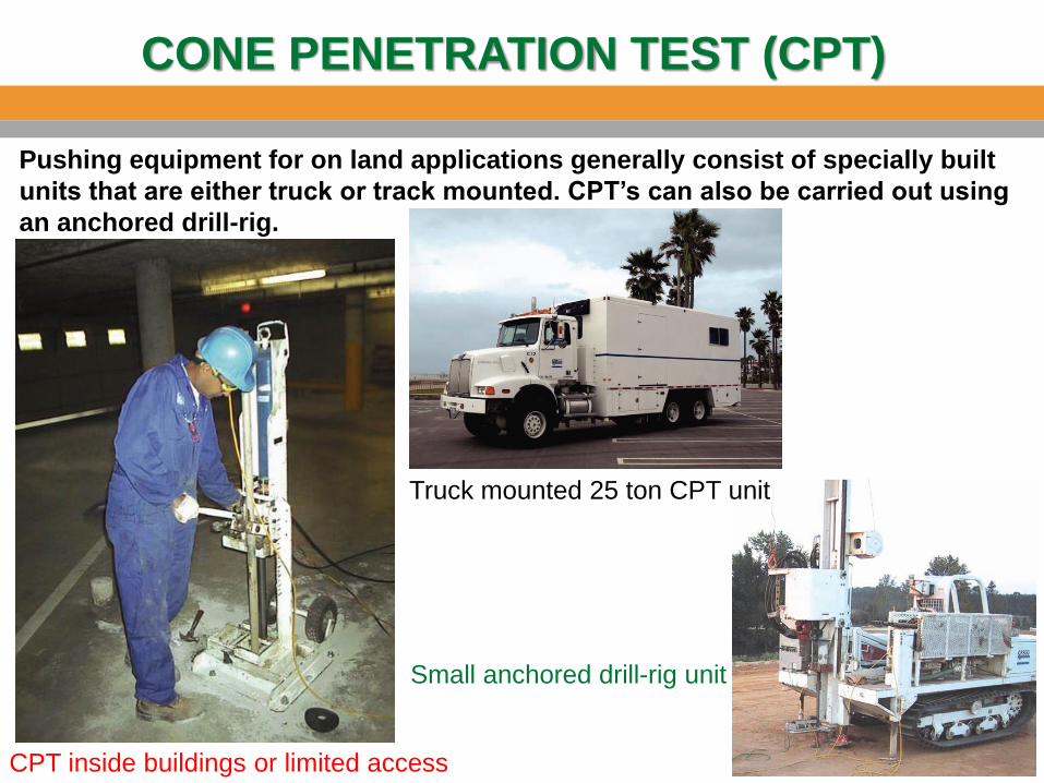
Pushing equipment for on land applications generally consist of specially built
units that are either truck or track mounted. CPT’s can also be carried out using
an anchored drill-rig.
CPT inside buildings or limited access
Small anchored drill-rig unit
Truck mounted 25 ton CPT unit
CONE PENETRATION TEST (CPT)
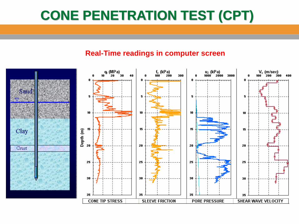
Real-Time readings in computer screen
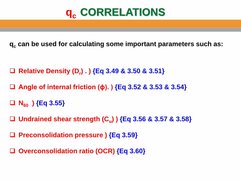
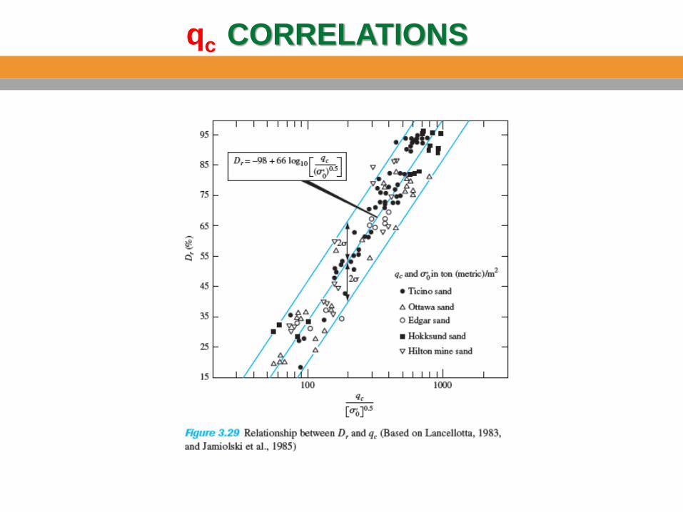
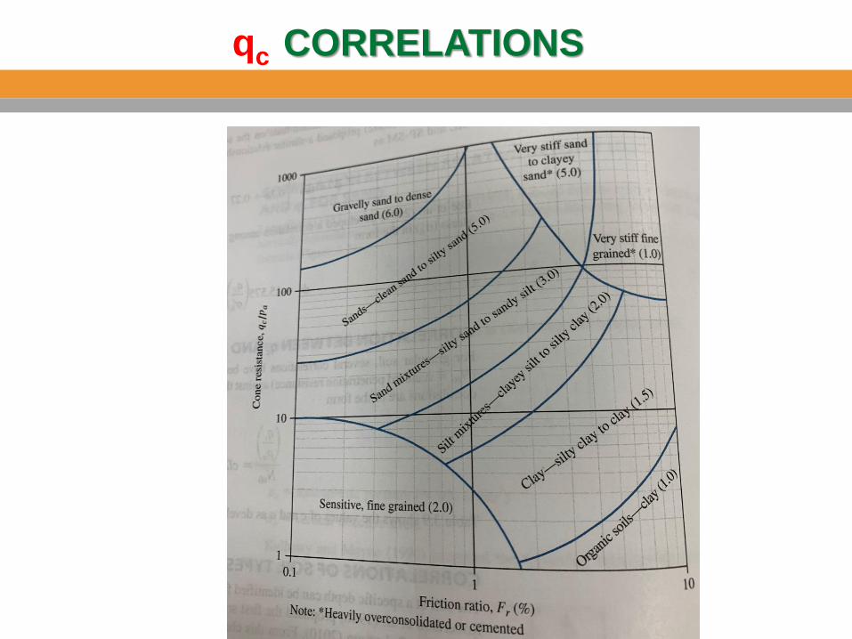
qc CORRELATIONS
qc can be used for calculating some important parameters such as:
Relative Density (Dr) . ) {Eq 3.49 & 3.50 & 3.51}
Angle of internal friction (ϕ). ) {Eq 3.52 & 3.53 & 3.54}
N60 ) {Eq 3.55}
Undrained shear strength (Cu) ) {Eq 3.56 & 3.57 & 3.58}
Preconsolidation pressure ) {Eq 3.59}
Overconsolidation ratio (OCR) {Eq 3.60}
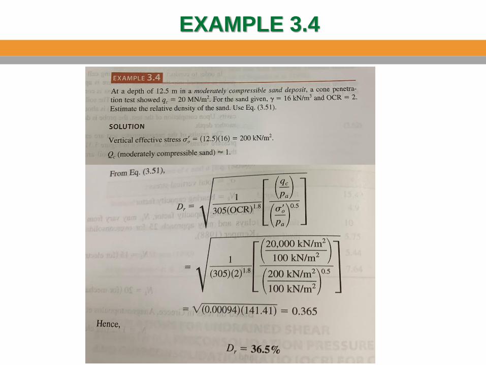
EXAMPLE 3.4
qc CORRELATIONS
qc CORRELATIONS
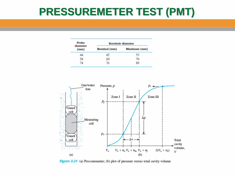
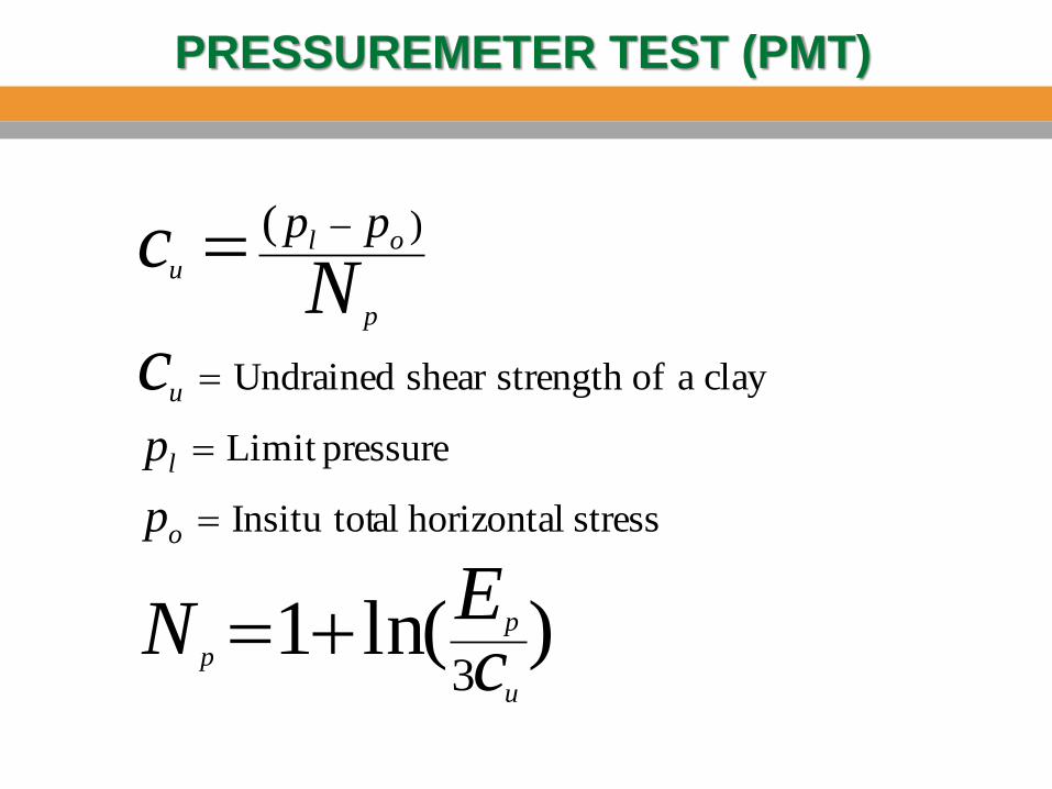
The pressuremeter test can be used to evaluate the stress-strain
response of a wide range of soils and rock. It consists of a probe with
three cells. The top and bottom ones are guard cells and the middle
is the measuring cell.
There are three basic types of pressuremeter devices, Pre-bored,
Self-bored and Full-displacement, each with different abilities and
challenges.
Advantages of PMT:
• Strong theoretical basis for interpretation
• Tests large volume of ground
Disadvantages of PMT:
• Complicated equipment and procedures
• Requires skilled operator
• Time consuming and expensive
• Equipment can be easily damaged
PRESSUREMETER TEST (PMT)
PRESSUREMETER TEST (PMT)
PRESSUREMETER TEST (PMT)
)ln(1
3
(
stress horizontal alInsitu tot
pressureLimit
clay a ofstrength shear Undrained
)
u
p
p
o
l
u
p
olu
cEN
cN
c
p
p
pp
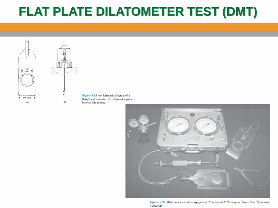
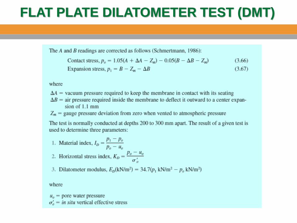
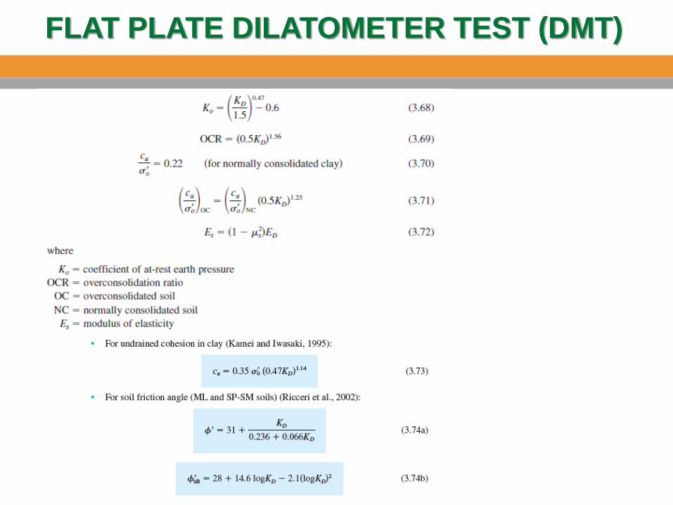
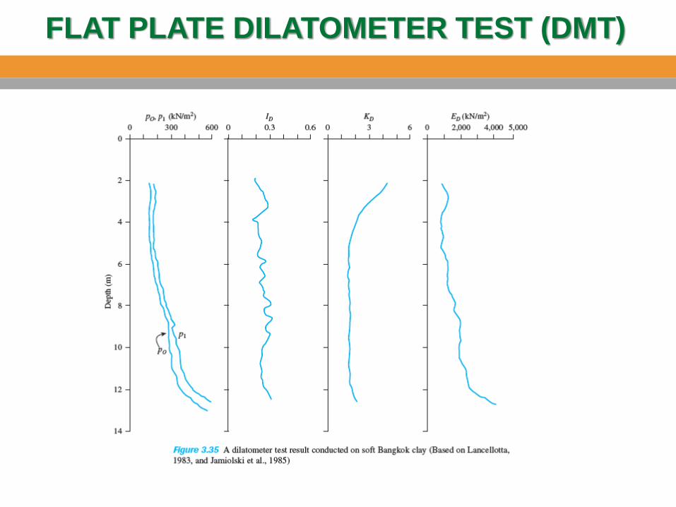
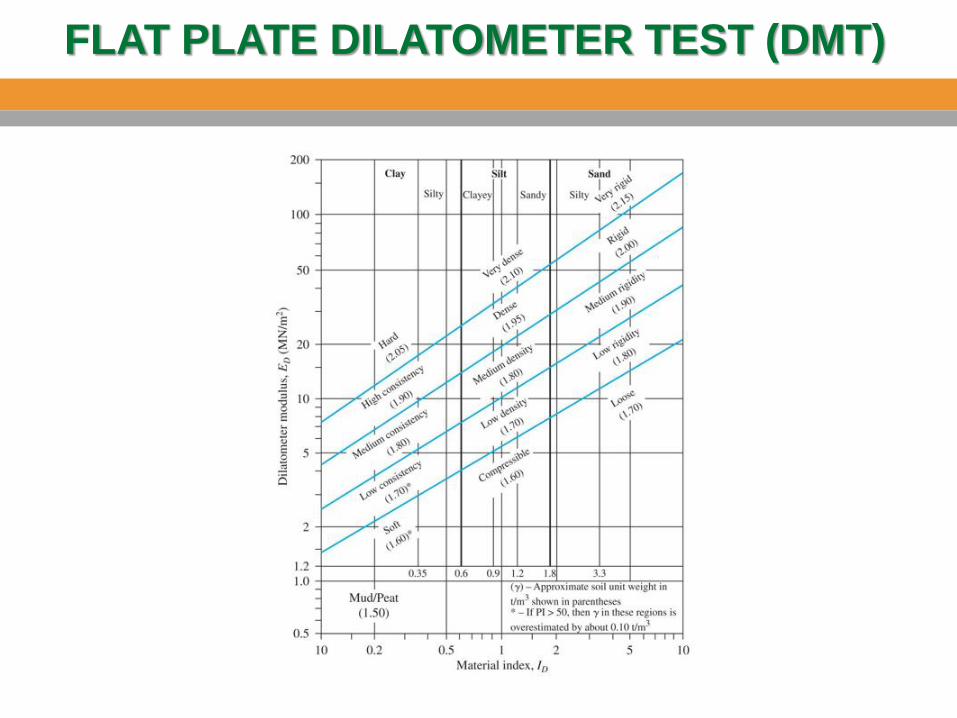
The flat plate dilatometer test (DMT) can be used to estimate a
wide range of geotechnical parameters in primarily softer soils.
Advantages of DMT:
• Simple and robust
• Repeatable and reliable data (not operator-dependent)
• Economical
Disadvantage of DMT:
• Difficult to push into dense and hard materials
• Weak theoretical basis for interpretation
• No soil sample
• Penetration can be restricted in gravel/cemented layers
FLAT PLATE DILATOMETER TEST (DMT)
FLAT PLATE DILATOMETER TEST (DMT)
FLAT PLATE DILATOMETER TEST (DMT)
FLAT PLATE DILATOMETER TEST (DMT)
FLAT PLATE DILATOMETER TEST (DMT)
FLAT PLATE DILATOMETER TEST (DMT)
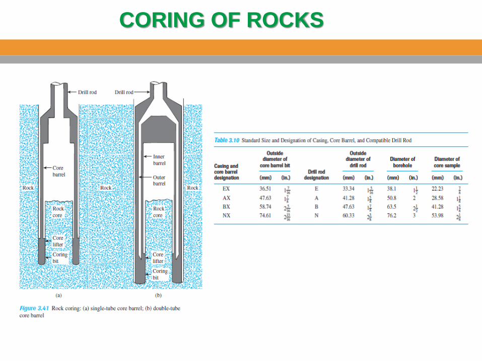
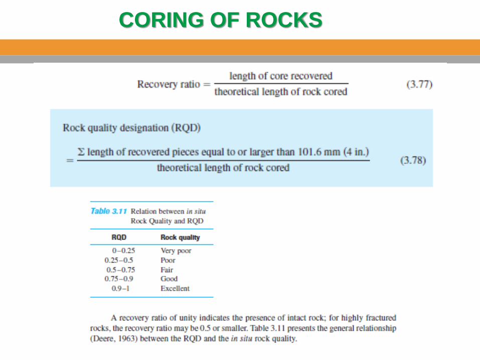
CORING OF ROCKS
CORING OF ROCKS
CORING OF ROCKS
Core barrel samplers are originally designed to sample rock.
Single tube sampler
The core barrel of the sampler rotates and this poses the possibility
of disturbing the sample by shearing the sample along certain weak
planes. Moreover, the cored samples are subjected to erosion and
disturbance by the drilling fluid.
The rock cores obtained can be highly disturbed and fractured
because of torsion.
Double tube samplers
The tube samplers do not rotate with the core barrels and the
samplers are not protected against the drilling fluid. The logging of
samples presents difficulty for highly fractured rock.
CORING OF ROCKS
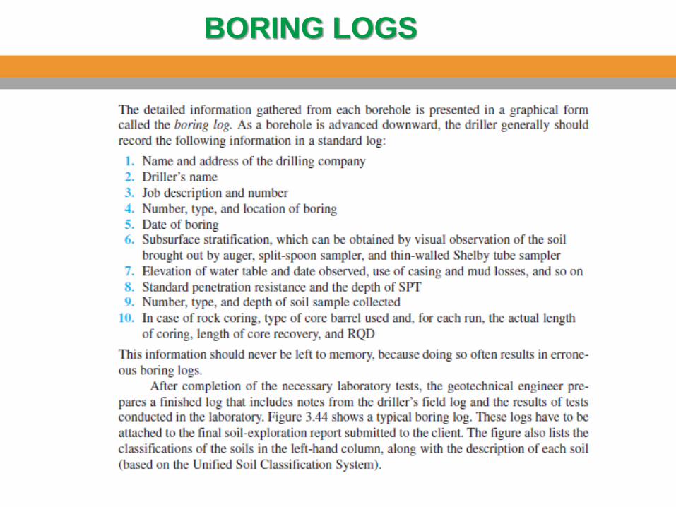
BORING LOGS
BORING LOGS
GEOPHYSICAL EXPLORATION
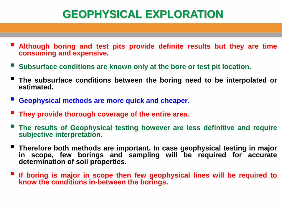
Although boring and test pits provide definite results but they are timeconsuming and expensive.
Subsurface conditions are known only at the bore or test pit location.
The subsurface conditions between the boring need to be interpolated orestimated.
Geophysical methods are more quick and cheaper.
They provide thorough coverage of the entire area.
The results of Geophysical testing however are less definitive and requiresubjective interpretation.
Therefore both methods are important. In case geophysical testing in majorin scope, few borings and sampling will be required for accuratedetermination of soil properties.
If boring is major in scope then few geophysical lines will be required toknow the conditions in-between the borings.
GEOPHYSICAL TEST METHODS
Advantages
Many geophysical tests are non-invasive and thus offer significant
benefits in cases where conventional drilling, testing, and sampling are
difficult (e.g., deposits of gravel, talus deposits) or where potentially
contaminated soils may occur in the subsurface.
In general, geophysical testing covers a relatively large area, thus
providing the opportunity to characterize large areas with few tests. It
is particularly well-suited to projects that have large longitudinal extent
compared to lateral extent (such as for new highway construction).
Geophysical measurement assesses the characteristics of soil and
rock at very small strains, typically on the order of 0.001 percent thus
providing information on truly elastic properties.
For the purpose of obtaining information on the subsurface,
geophysical methods are relatively inexpensive when considering cost
relative to the relatively large areas over which information can be
obtained.
GEOPHYSICAL TEST METHODS
Disadvantages
Most methods work best for situations in which there is a large
difference in stiffness between adjacent subsurface units.
It is difficult to develop good stratigraphic profiling if the general
stratigraphy consists of hard material over soft material
Results are generally interpreted qualitatively and therefore useful
results can only be obtained by an experienced engineer or geologist
familiar with the particular testing method.
Specialized equipment is required (compared to more conventional
subsurface exploration tools).
GEOPHYSICAL TEST METHODS
There are a number of different geophysical in-situ tests that can
be used for stratigraphic information and in the determination of
engineering properties. The most common methods are:
Three methods
1.Seismic Refraction Survey
2.Cross-Hole Seismic Survey
3.Electrical Resistivity Survey
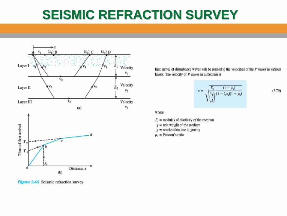
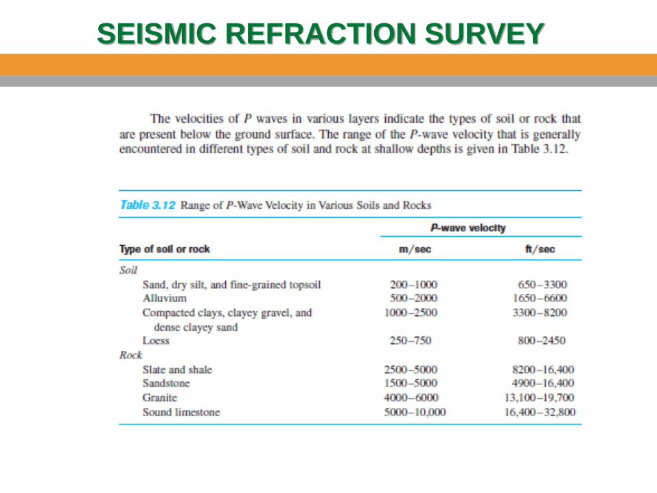
SEISMIC REFRACTION SURVEY
Useful in obtaining preliminary information about the thickness of the layering of
various soils and the depth to rock or hard soil.
It is conducted by impacting the surface and observing the first arrival of the
disturbance (stress wave) at several other points.
The impact can be created by a hammer blow or by a small explosive charge.
The first arrival of disturbance waves at various points can be recorded by
geophones.
A graph of travel time versus distance is established
Two types of stress waves:
o P waves (plane waves)
o S waves (shear waves)
P faster than S.
SEISMIC REFRACTION SURVEY
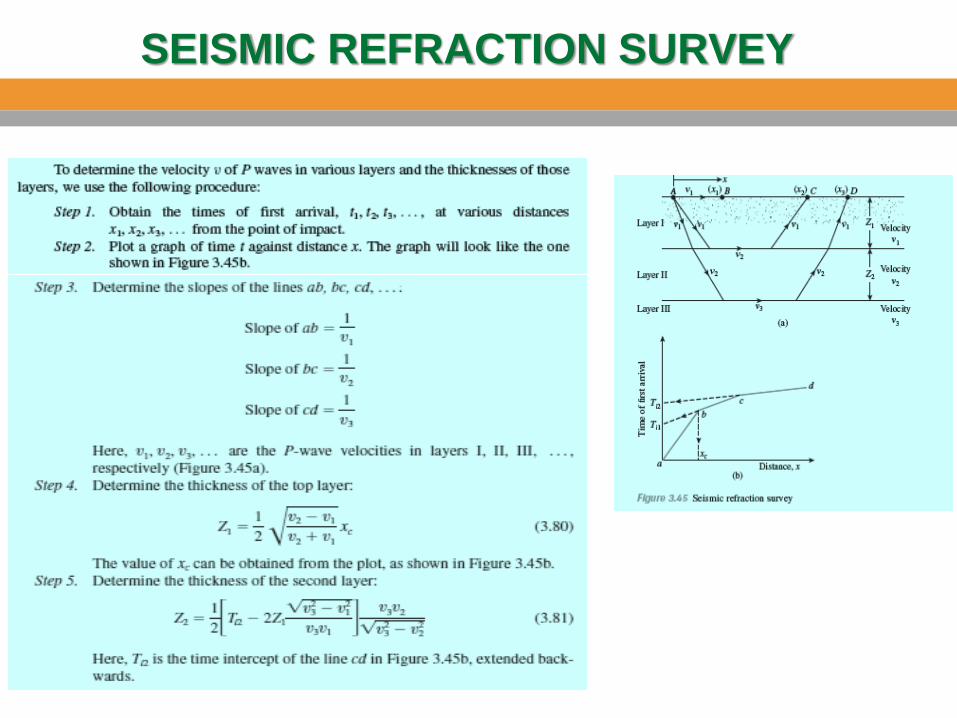
SEISMIC REFRACTION SURVEY
SEISMIC REFRACTION SURVEY
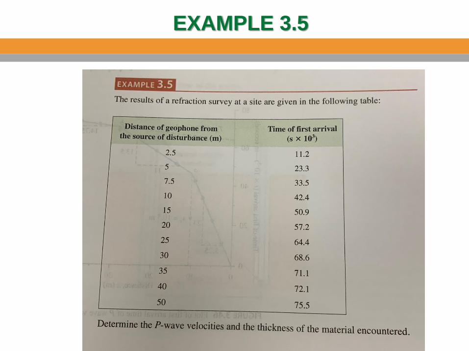
EXAMPLE 3.5
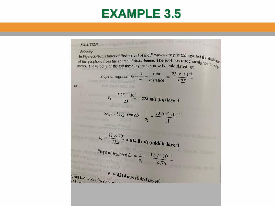
EXAMPLE 3.5
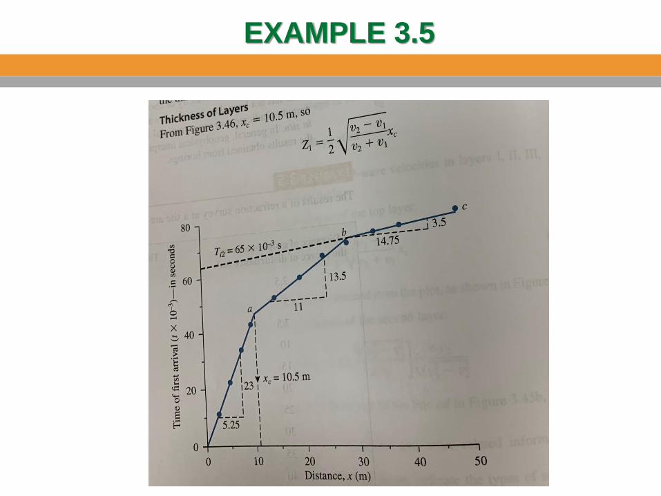
EXAMPLE 3.5
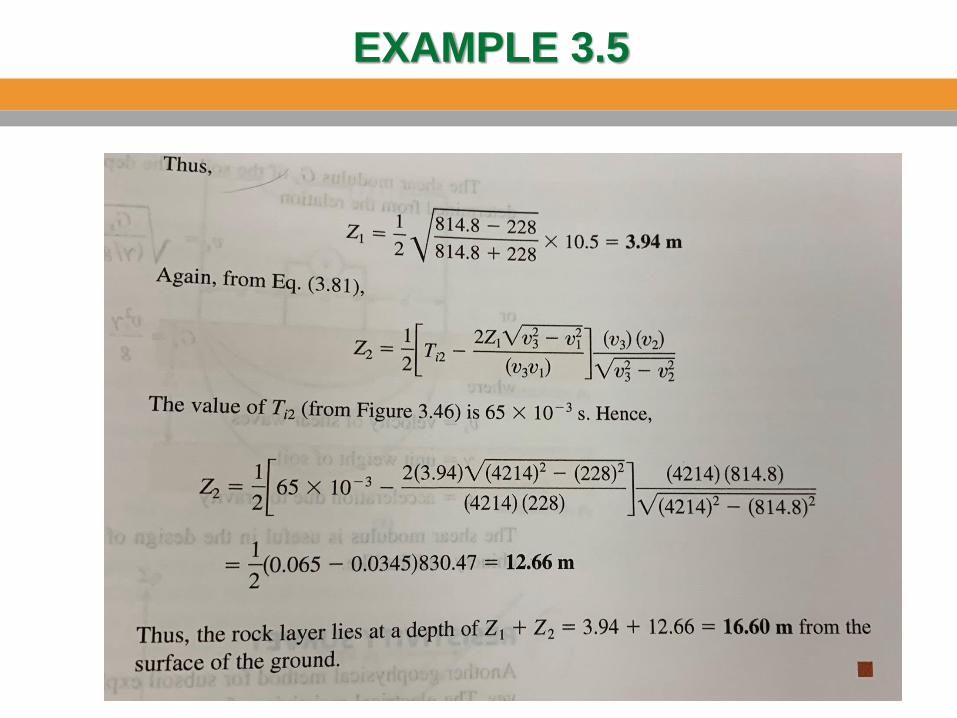
EXAMPLE 3.5
SEISMIC REFRACTION SURVEY
Advantages :
It is fast and not hindered by the presence of boulders
Equipment is lightweight and can be carried in the field.
Two persons are enough
Disadvantages :
It can not detect a subsurface layer whose sonic velocity is
slower than that of the layer above (peat, soft clay,…)
Wrong interpretation of the subsurface materials when the soil is
saturated and the ground water table is not detected.
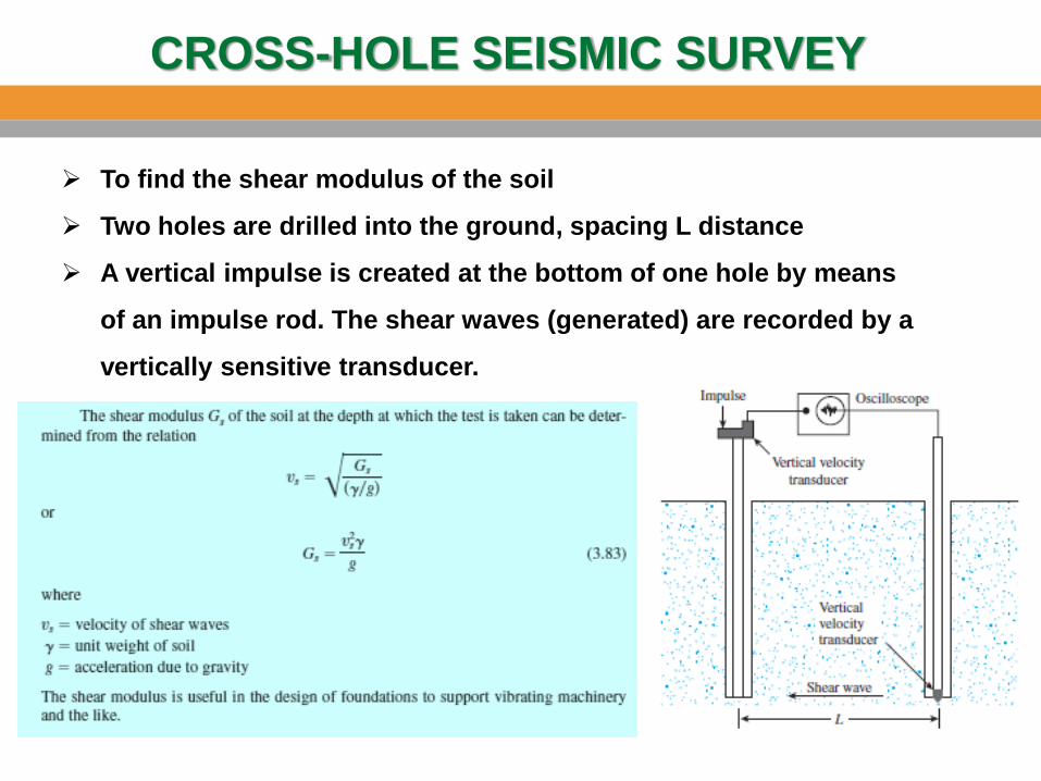
CROSS-HOLE SEISMIC SURVEY
To find the shear modulus of the soil
Two holes are drilled into the ground, spacing L distance
A vertical impulse is created at the bottom of one hole by means
of an impulse rod. The shear waves (generated) are recorded by a
vertically sensitive transducer.
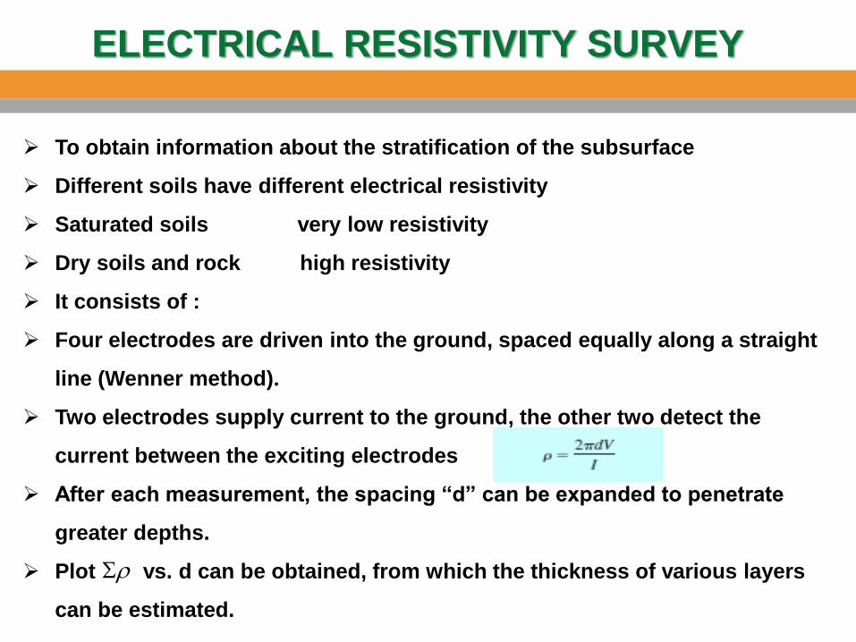
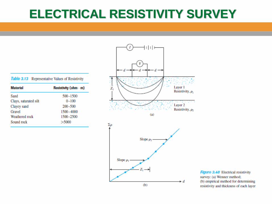
ELECTRICAL RESISTIVITY SURVEY
To obtain information about the stratification of the subsurface
Different soils have different electrical resistivity
Saturated soils very low resistivity
Dry soils and rock high resistivity
It consists of :
Four electrodes are driven into the ground, spaced equally along a straight
line (Wenner method).
Two electrodes supply current to the ground, the other two detect the
current between the exciting electrodes
After each measurement, the spacing “d” can be expanded to penetrate
greater depths.
Plot vs. d can be obtained, from which the thickness of various layers
can be estimated.
ELECTRICAL RESISTIVITY SURVEY
ELECTRICAL RESISTIVITY SURVEY
Advantages :
It is fast and low cost
It can detect underlying layer whose resistivity are either higher
of lower than overlying layers
Disadvantages :
Sensitive to variations in both soil conditions and electrode
placement
Can not distinguish between soft and stiff clays.
GEOTECHNICAL REPORT
Upon completion of the geotechnical investigation and analysis, the
information and findings must be compiled in a standard report format.
The report serves as the permanent record of all geotechnical data known to
be pertinent to the project and is referred to throughout the design,
construction, and service life of the project.
The data and recommendations are typically compiled in a Geotechnical
Report. The intent of the Geotechnical Report is to present the data collected
in a clear manner, to draw conclusions from the data, and to make
recommendations for the geotechnical aspects of the project.
The primary clients that use the report are roadway designers, Bridge
Engineers, construction personnel, and contractors.
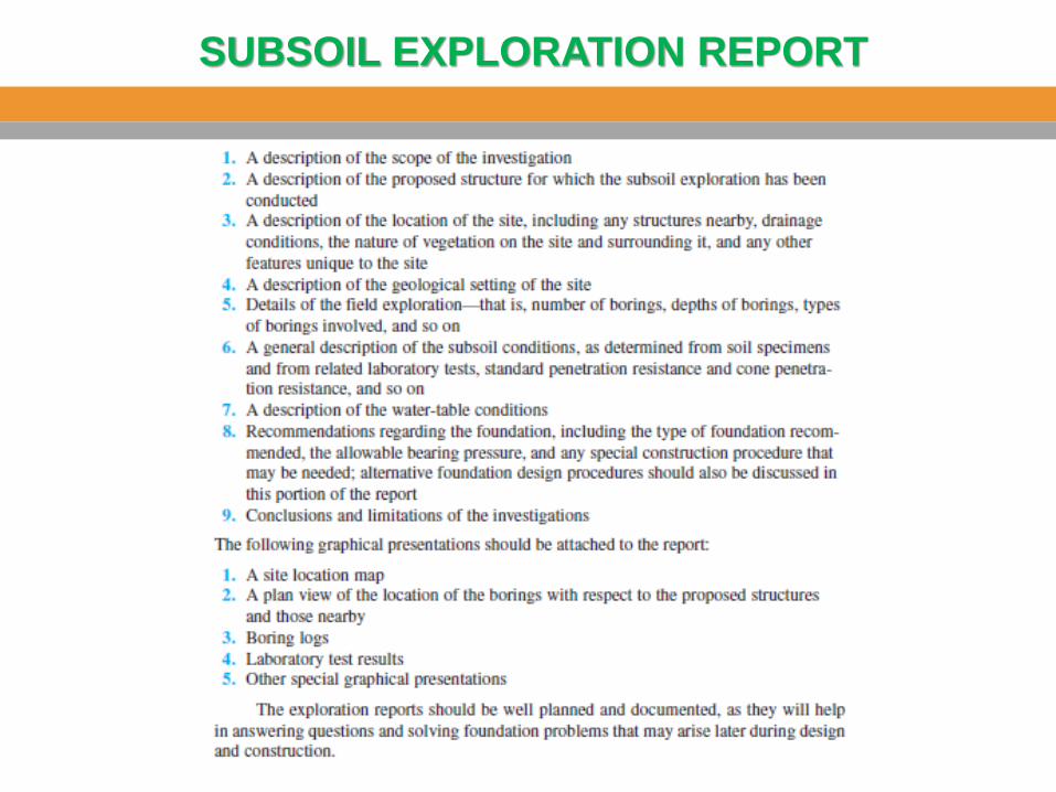
SUBSOIL EXPLORATION REPORT