Embed Size (px)
Citation preview
7/30/2019 Chapter 3-thermodynamics final.doc
http://slidepdf.com/reader/full/chapter-3-thermodynamics-finaldoc 1/26
Chapter 3
THE FIRST LAWOF THERMODYNAMICS
Energy interactions between a system and its surroundings across theboundary in the form of heat and work have been discussed separately inthe previous chapter.So far, no attempt has been made to relate these interactions betweenthemselves and with the energy content of the system.
First law of thermodynamics, often called as law of conservation of
energy, relating work, heat, and energy content of the system will bediscussed in detail in this chapter.
3.1 First Law of Thermodynamics
In its more general form, the first law may be stated as follows
“When energy is either transferred or transformed, the final totalenergy present in all forms must precisely equal the original total energy ”.
It is based on the experimental observations and can not be provedmathematically. All the observations made so far, confirm the correctnessof this law.
3.2 First Law of Thermodynamics for a Closed System
Undergoing a Process
Thermodynamics I [MIME3110] 2
7/30/2019 Chapter 3-thermodynamics final.doc
http://slidepdf.com/reader/full/chapter-3-thermodynamics-finaldoc 2/26
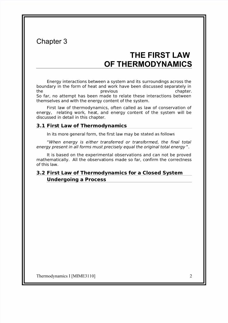
First law can be written for a closed system in an equation form as
=+systemtheof content
energytheinChange
systemthe
left Energy
systemthentoi
entered Energy
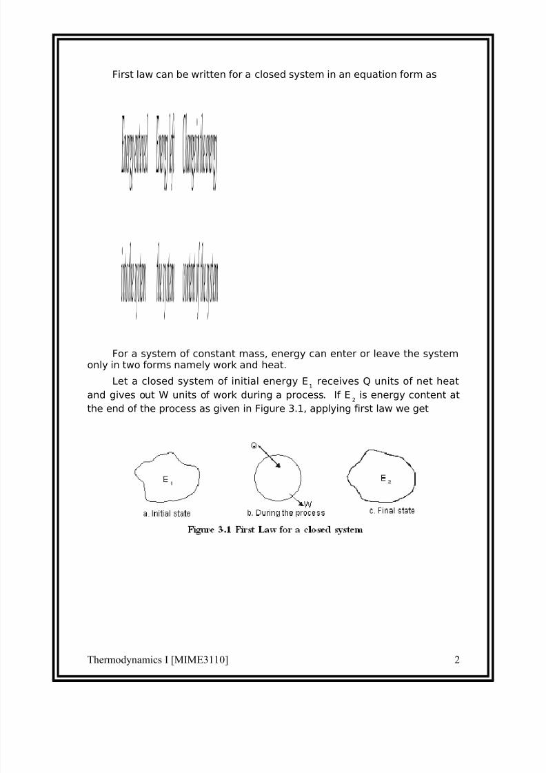
For a system of constant mass, energy can enter or leave the systemonly in two forms namely work and heat.
Let a closed system of initial energy E1
receives Q units of net heat
and gives out W units of work during a process. If E2
is energy content at
the end of the process as given in Figure 3.1, applying first law we get
Thermodynamics I [MIME3110] 2

7/30/2019 Chapter 3-thermodynamics final.doc
http://slidepdf.com/reader/full/chapter-3-thermodynamics-finaldoc 3/26
Q − W = (E2 − E
1)
...(3.1)
Where the total energy content
Ε = Internal Energy + Kinetic energy + Potential
energy
= U +c g
mC 2
2
1+ mgz
The term internal energy usually denoted by the letter U is the energydue to such factors as electron spin and vibrations, molecular motion andchemical bond.
Kinetic energy term is due to the system movement with a velocity C.For stationary systems this term will be zero. The term g
cis a constant of
value 1 in SI unit. It will be dropped here after since SI unit is followedthroughout the book.
Potential energy term is due to the location of the system in thegravitational field. It remains constant for a stationary system. The unit of energy in SI is kJ.
3.3 The Thermodynamic Property Enthalpy
Consider a stationary system of fixed mass undergoing a quasi-
equilibrium constant pressure process
Applying first law
Q12
− 1W
2= E
2− E
1
where E2 − E
1= (U
2 − U
1) + m(C2
2 − C
1
2) + mg(Z2 − Z
1)
= U2 − U
1since it is a stationary system.
also1W
2 = p(V
2 − V
1)
= p2V
2 − p
1V
1
∴ Q12
= (p2V
2 − p
1V
1) + (U
2 − U
1)
Thermodynamics I [MIME3110] 2

7/30/2019 Chapter 3-thermodynamics final.doc
http://slidepdf.com/reader/full/chapter-3-thermodynamics-finaldoc 4/26
∴Q12
= (U2
+ p2V
2) − (U
1+ p
1V
1)
The terms within brackets are all properties depending on the endstates. This combination of properties may be regarded as a single propertyknown as enthalpy. It is usually denoted by the letter H.
ie H = U + pV
...(3.3a)
(or) h = u + pv
...(3.3b)
Where h is specific enthalpy in kJ/kg
u is specific internal energy in kJ/kg and
v is specific volume in m3/kg
3.4 Flow Energy
Flow energy is defined as the energy required to move a mass into thea control volume against a pressure. Consider a mass of volume V enteringinto a control volume as given in the Figure 3.2 against a pressure p.
Thermodynamics I [MIME3110] 2

7/30/2019 Chapter 3-thermodynamics final.doc
http://slidepdf.com/reader/full/chapter-3-thermodynamics-finaldoc 5/26
The Flow energy = Work done in moving the mass
= Force × distance
= pA × dx
= p × (Adx)
= pV
...(3.4)
Therefore, Enthalpy = Internal energy + Flow energy
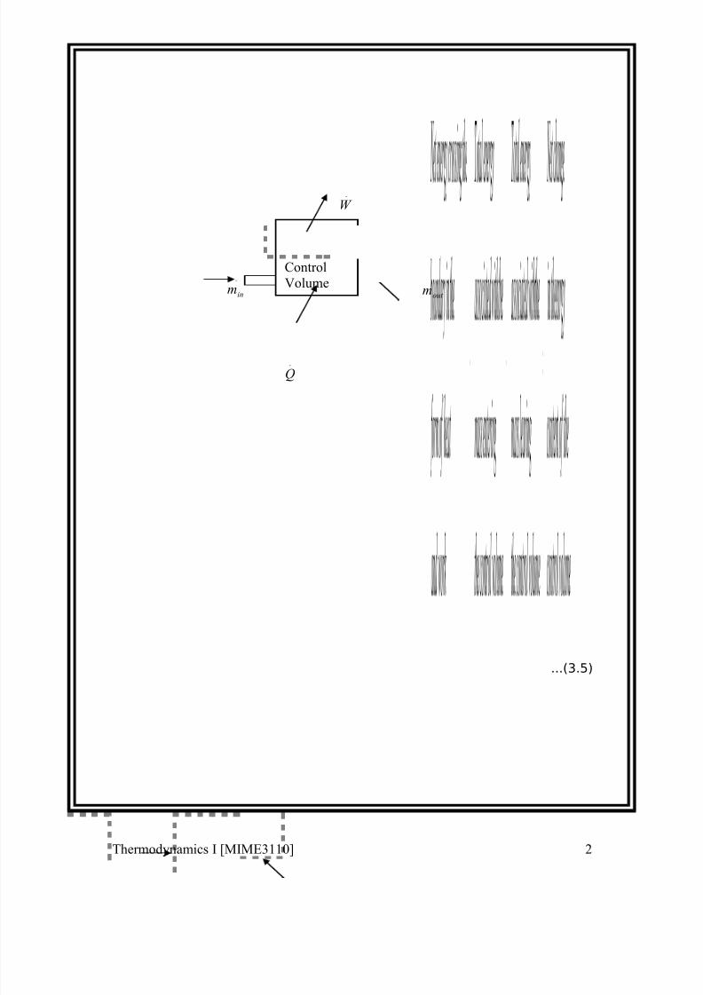
3.5 First Law of Thermodynamics for a Control Volume
Mass simultaneously entering and leaving the system is a verycommon phenomenon in most of the engineering applications. Controlvolume concept is applied to these devices by assuming suitable controlsurfaces.
To analyze these control volume problems, conservation of mass andenergy concepts are to be simultaneously considered.
Energy may cross the control surface not only in the form of heat andwork but also by total energy associated with the mass crossing theboundaries. Hence apart from kinetic, potential and internal energies, flowenergy should also be taken into account.
Conservation of mass
Thermodynamics I [MIME3110] 2
7/30/2019 Chapter 3-thermodynamics final.doc
http://slidepdf.com/reader/full/chapter-3-thermodynamics-finaldoc 6/26
=
+
volumecontrol
theof contentmasstheinchange Net
volumecontrol
theleavingmassTotal
volumecontrol
theenteringmassTotal
Conservation of energy
Thermodynamics I [MIME3110] 2
7/30/2019 Chapter 3-thermodynamics final.doc
http://slidepdf.com/reader/full/chapter-3-thermodynamics-finaldoc 7/26
=−+
volumecontrol
theof content
theenrgyinchange Net
volumecontrolthe
leavingmass
thewithassociatedenergyTotal
volumecontrolthe
enteringmass
thewithassociatedenergyTotal
workand
heatof form
theinboundarythecrossingenergy Net
...(3.5)
Thermodynamics I [MIME3110] 2
.
Q
.
W
.
inm.
out m
Control
Volume

7/30/2019 Chapter 3-thermodynamics final.doc
http://slidepdf.com/reader/full/chapter-3-thermodynamics-finaldoc 8/26
Figure 3.3 First Law of Thermodynamics Applied to a control
Volume
As a rate equation, it becomes
[ ] [ ]CV
out
out
in
in E Zg C
hm Zg C
hmW Q ∆=
++−
+++− ∑∑
22
22
...(3.6)
3.6 The Steady-state Flow Process
When a flow process is satisfying the following conditions, it is known
as a steady flow process.
1. The mass and energy content of the control volume remainsconstant with time.
2. The state and energy of the fluid at inlet, at the exit and at everypoint within the control volume are time independent.
3. The rate of energy transfer in the form of work and heat across thecontrol surface is constant with time.
Therefore for a steady flow process...(3.7)...(3.7)
also...(3.8)
...(3.9)
For problem of single inlet stream and single outlet stream
[ ] ( )
−+
−+−=− g Z Z C C
hhmW Q 12
2
1
2
212
2)(
...(3.10)
This equation is commonly known as steady flow energy equation (SFEE).
3.7 Application of SFEE
Thermodynamics I [MIME3110] 2
Control Surface
∑∑ = out in mm
[ ] 0=∆ CV E
[ ] 022
22
=
++−
+++− ∑∑ Zg
C hm Zg
C hmW Q
out
out
in
in
7/30/2019 Chapter 3-thermodynamics final.doc
http://slidepdf.com/reader/full/chapter-3-thermodynamics-finaldoc 9/26
SFEE governs the working of a large number of components used inmany engineering practices. In this section a brief analysis of suchcomponents working under steady flow conditions are given and therespective governing equations are obtained.
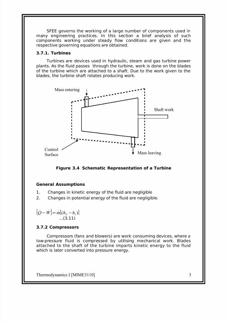
3.7.1. Turbines
Turbines are devices used in hydraulic, steam and gas turbine power
plants. As the fluid passes through the turbine, work is done on the blades
of the turbine which are attached to a shaft. Due to the work given to theblades, the turbine shaft rotates producing work.
Figure 3.4 Schematic Representation of a Turbine
General Assumptions
1. Changes in kinetic energy of the fluid are negligible
2. Changes in potential energy of the fluid are negligible.
[ ])( 12 hhmW Q −=−
...(3.11)
3.7.2 Compressors
Compressors (fans and blowers) are work consuming devices, where alow-pressure fluid is compressed by utilising mechanical work. Bladesattached to the shaft of the turbine imparts kinetic energy to the fluidwhich is later converted into pressure energy.
Thermodynamics I [MIME3110] 3
Mass entering
Mass leaving
Shaft work
Control
Surface

7/30/2019 Chapter 3-thermodynamics final.doc
http://slidepdf.com/reader/full/chapter-3-thermodynamics-finaldoc 10/26
Figure 3.5 Schematic Representation of a Compresso
General Assumptions
1. Changes in the kinetic energy of the fluid are negligible
2. Changes in the potential energy of the fluid are negligible
Governing Equation
Applying the above equations SFEE becomes
[ ])( 12 hhmW Q −=−
...(3.12)
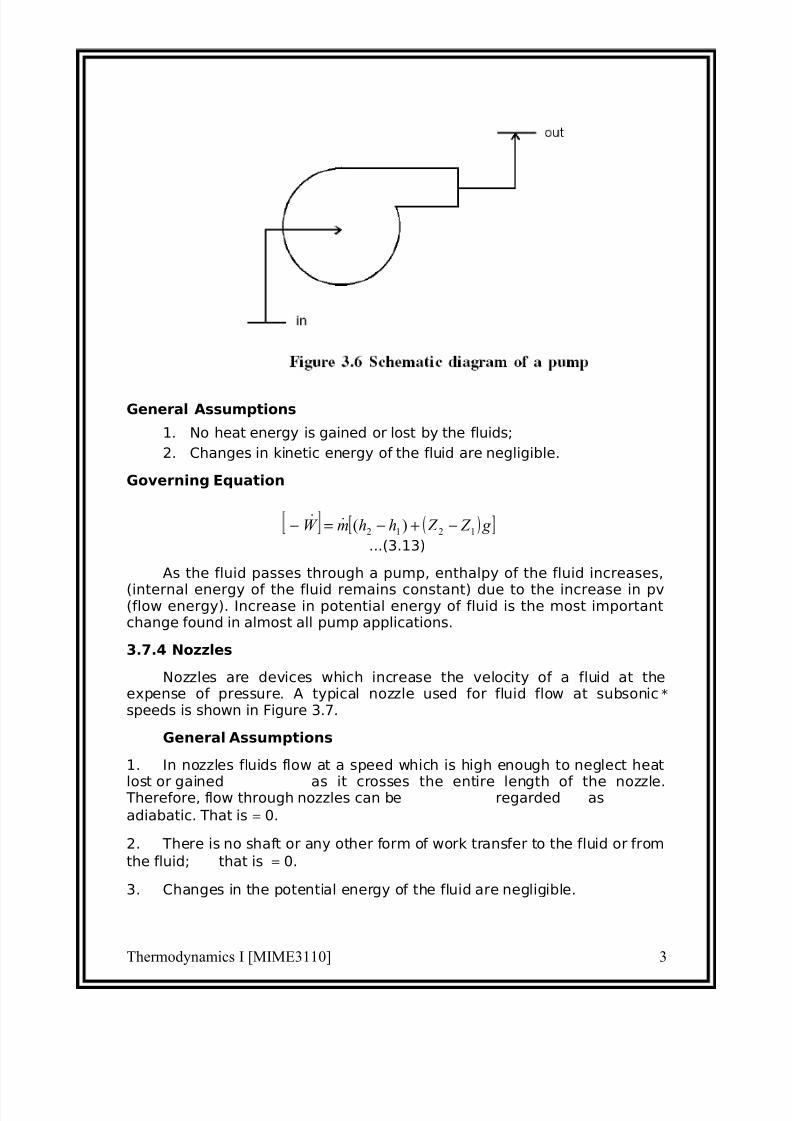
3.7.3 Pumps
Similar to compressors pumps are also work consuming devices. Butpumps handle incompressible fluids, whereas compressors deal withcompressible fluids.
Thermodynamics I [MIME3110] 3
Mass entering
Mass leaving
Shaft work
ControlSurface
7/30/2019 Chapter 3-thermodynamics final.doc
http://slidepdf.com/reader/full/chapter-3-thermodynamics-finaldoc 11/26
General Assumptions
1. No heat energy is gained or lost by the fluids;
2. Changes in kinetic energy of the fluid are negligible.
Governing Equation
( )[ ] g Z Z hhmW 1212 )( −+−=−
...(3.13)
As the fluid passes through a pump, enthalpy of the fluid increases,
(internal energy of the fluid remains constant) due to the increase in pv(flow energy). Increase in potential energy of fluid is the most importantchange found in almost all pump applications.
3.7.4 Nozzles
Nozzles are devices which increase the velocity of a fluid at theexpense of pressure. A typical nozzle used for fluid flow at subsonic*
speeds is shown in Figure 3.7.
General Assumptions
1. In nozzles fluids flow at a speed which is high enough to neglect heat
lost or gained as it crosses the entire length of the nozzle. Therefore, flow through nozzles can be regarded as
adiabatic. That is = 0.
2. There is no shaft or any other form of work transfer to the fluid or from
the fluid; that is = 0.
3. Changes in the potential energy of the fluid are negligible.
Thermodynamics I [MIME3110] 3
7/30/2019 Chapter 3-thermodynamics final.doc
http://slidepdf.com/reader/full/chapter-3-thermodynamics-finaldoc 12/26
Governing Equation
)(2
02
)(
21
2
1
2
2
2
1
2
212
hhC C
C C hh
−=
−
=
−+−
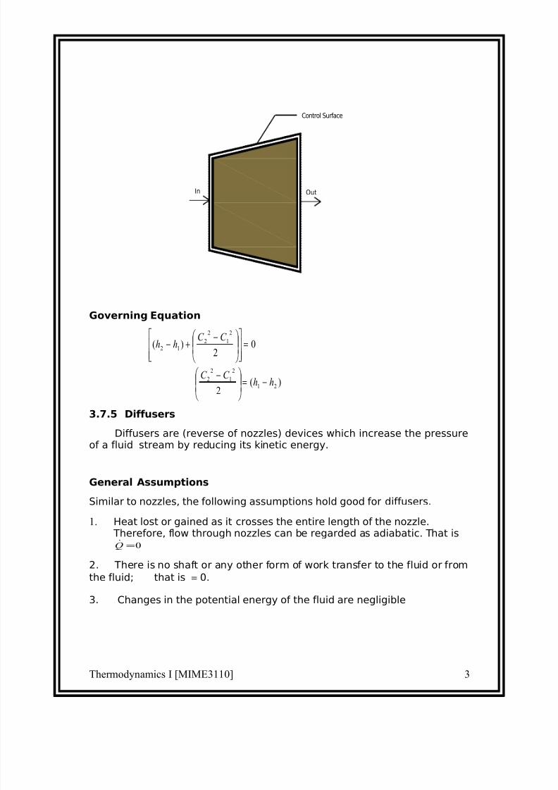
3.7.5 Diffusers
Diffusers are (reverse of nozzles) devices which increase the pressureof a fluid stream by reducing its kinetic energy.
General Assumptions
Similar to nozzles, the following assumptions hold good for diffusers.
1. Heat lost or gained as it crosses the entire length of the nozzle. Therefore, flow through nozzles can be regarded as adiabatic. That is
0=Q
2. There is no shaft or any other form of work transfer to the fluid or from
the fluid; that is = 0.
3. Changes in the potential energy of the fluid are negligible
Thermodynamics I [MIME3110] 3
In Out
Control Surface
7/30/2019 Chapter 3-thermodynamics final.doc
http://slidepdf.com/reader/full/chapter-3-thermodynamics-finaldoc 13/26
Governing Equation
...(3.14)
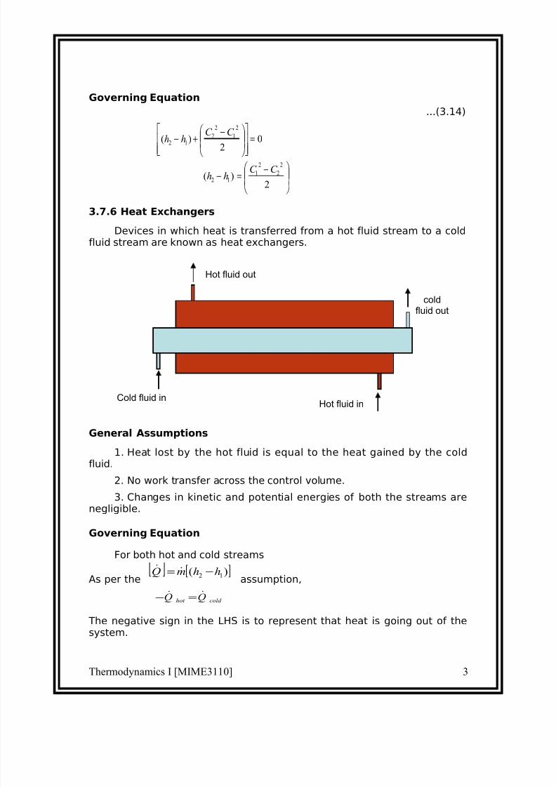
3.7.6 Heat Exchangers
Devices in which heat is transferred from a hot fluid stream to a coldfluid stream are known as heat exchangers.
General Assumptions
1. Heat lost by the hot fluid is equal to the heat gained by the coldfluid.
2. No work transfer across the control volume.
3. Changes in kinetic and potential energies of both the streams arenegligible.
Governing Equation
For both hot and cold streams
As per the assumption,
cold hot QQ =−
The negative sign in the LHS is to represent that heat is going out of thesystem.
Thermodynamics I [MIME3110] 3
−=−
=
−+−
2)(
02
)(
2
2
2
112
2
1
2
212
C C hh
C C hh
Hot fluid out
Cold fluid in
coldfluid out
Hot fluid in
[ ])( 12 hhmQ −=
7/30/2019 Chapter 3-thermodynamics final.doc
http://slidepdf.com/reader/full/chapter-3-thermodynamics-finaldoc 14/26
)()( 1221 hhmhhm ch −=−
...(3.15)
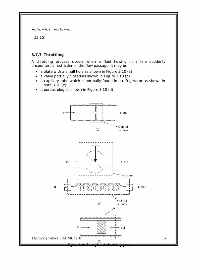
3.7.7 Throttling
A throttling process occurs when a fluid flowing in a line suddenlyencounters a restriction in the flow passage. It may be
• a plate with a small hole as shown in Figure 3.10 (a)
• a valve partially closed as shown in Figure 3.10 (b)
• a capillary tube which is normally found in a refrigerator as shown inFigure 3.10 (c)
• a porous plug as shown in Figure 3.10 (d)
Thermodynamics I [MIME3110] 3

7/30/2019 Chapter 3-thermodynamics final.doc
http://slidepdf.com/reader/full/chapter-3-thermodynamics-finaldoc 15/26
V
General assumptions
1. No heat energy is gained or lost by the fluid; ie., = 0
2. There is typically some increase in velocity in a throttle, but both inletand exit kinetic energies are usually small enough to beneglected.
3. There is no means for doing work; ie., = 0.
4. Changes in potential energy of the fluid is negligible.
Governing Equation
h2 = h1
...(3.16)
Therefore, throttling is an isenthalpic process.
3.8 First Law for a Cyclic Process
In a cyclic process the system is taken through a series of processesand finally returned to its original state. The end state of a cyclic process isidentical with the state of the system at the beginning of the cycle. This ispossible if the energy level at the beginning and end of the cyclic processare also the same. In other words, the net energy change in a cyclicprocess is zero.
Thermodynamics I [MIME3110] 3
1
2
Path A
Path B
p
7/30/2019 Chapter 3-thermodynamics final.doc
http://slidepdf.com/reader/full/chapter-3-thermodynamics-finaldoc 16/26
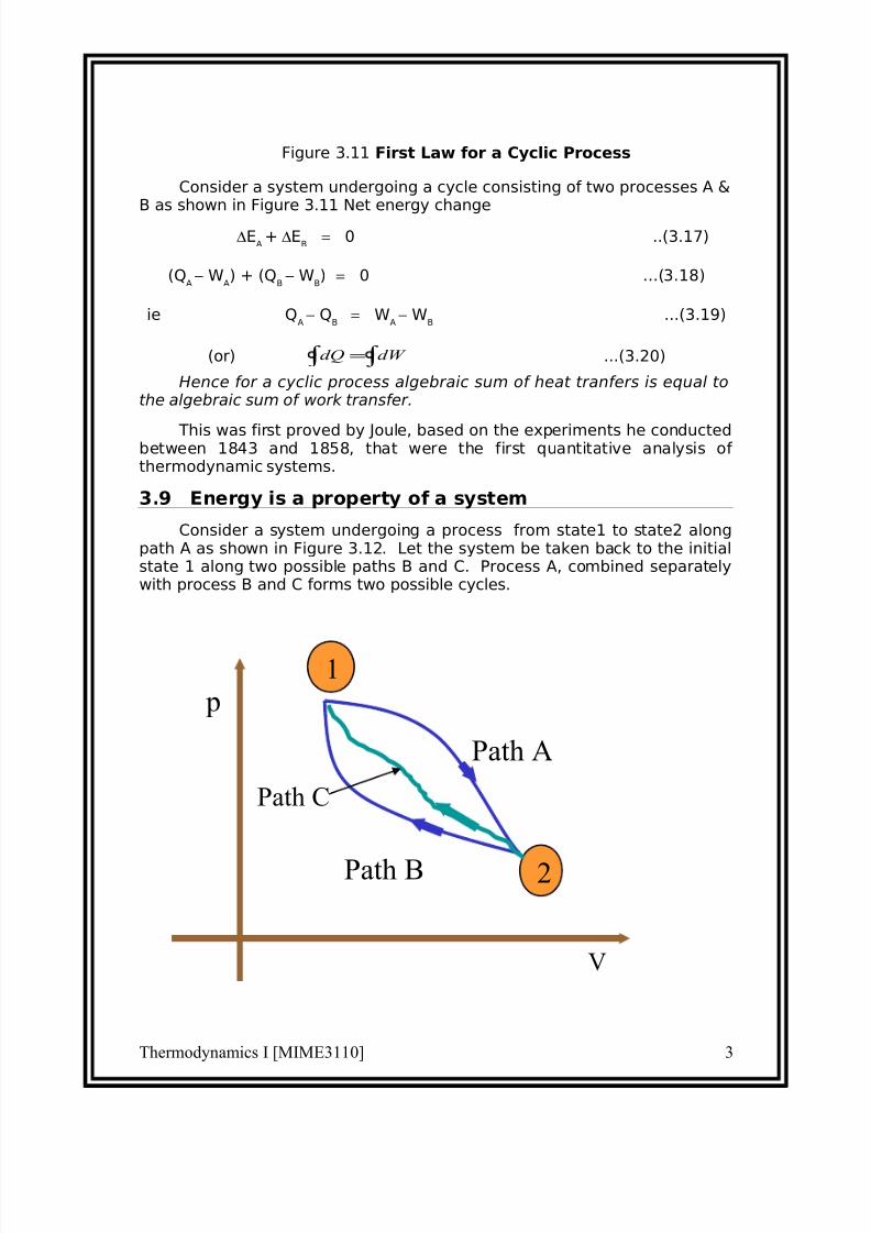
Figure 3.11 First Law for a Cyclic Process
Consider a system undergoing a cycle consisting of two processes A &B as shown in Figure 3.11 Net energy change
∆EA+ ∆E
B = 0 ..(3.17)
(QA
− WA) + (Q
B− W
B) = 0 ...(3.18)
ie QA
− QB
= WA
− WB
...(3.19)
(or) ∫ ∫ = dW dQ ...(3.20)
Hence for a cyclic process algebraic sum of heat tranfers is equal tothe algebraic sum of work transfer.
This was first proved by Joule, based on the experiments he conductedbetween 1843 and 1858, that were the first quantitative analysis of thermodynamic systems.
3.9 Energy is a property of a system
Consider a system undergoing a process from state1 to state2 alongpath A as shown in Figure 3.12. Let the system be taken back to the initialstate 1 along two possible paths B and C. Process A, combined separatelywith process B and C forms two possible cycles.
Thermodynamics I [MIME3110] 3
1
2
Path A
Path B
Path C
p
V

7/30/2019 Chapter 3-thermodynamics final.doc
http://slidepdf.com/reader/full/chapter-3-thermodynamics-finaldoc 17/26
Figure 3.12 Illustration to show that energy is property
Cycle 1A2B1
QA + QB = [WA + WB]
QA
− WA = −[Q
B− W
B]
∆EA
= −∆EB
...(3.21)
Cycle 1A2C1
QA
+ QC = [W
A+ W
C]
QA
− WA = −[Q
C− W
C]
∆EA = −∆EC ...(3.22)
From Equation (3.21) and (3.22) it can be concluded that energychange in path B and path C are equal and hence energy is a pointfunction depending only on the end states.
It has been already shown that all the properties are point functionsand hence energy is also a property of the system.
3.10 Specific Heat at Constant Volume and at ConstantPressure
Specific heat at constant volume of a substance is the amount of heat
added to rise the temperature of unit mass of the given substance by 1degree at constant volume
From first law for a stationary closed system undergoing a process
dQ = pdV + dU or dq = pdv + du
For a constant volume process
dQ = dU or dq = du
∴
or du = CvdT
...(3.23)
Similarly specific heat at constant pressure is the quantity of heat added torise the temperature of unit mass of the given substance by 1 degree atconstant pressure
wheredQ = pdV + dU
Thermodynamics I [MIME3110] 3
7/30/2019 Chapter 3-thermodynamics final.doc
http://slidepdf.com/reader/full/chapter-3-thermodynamics-finaldoc 18/26
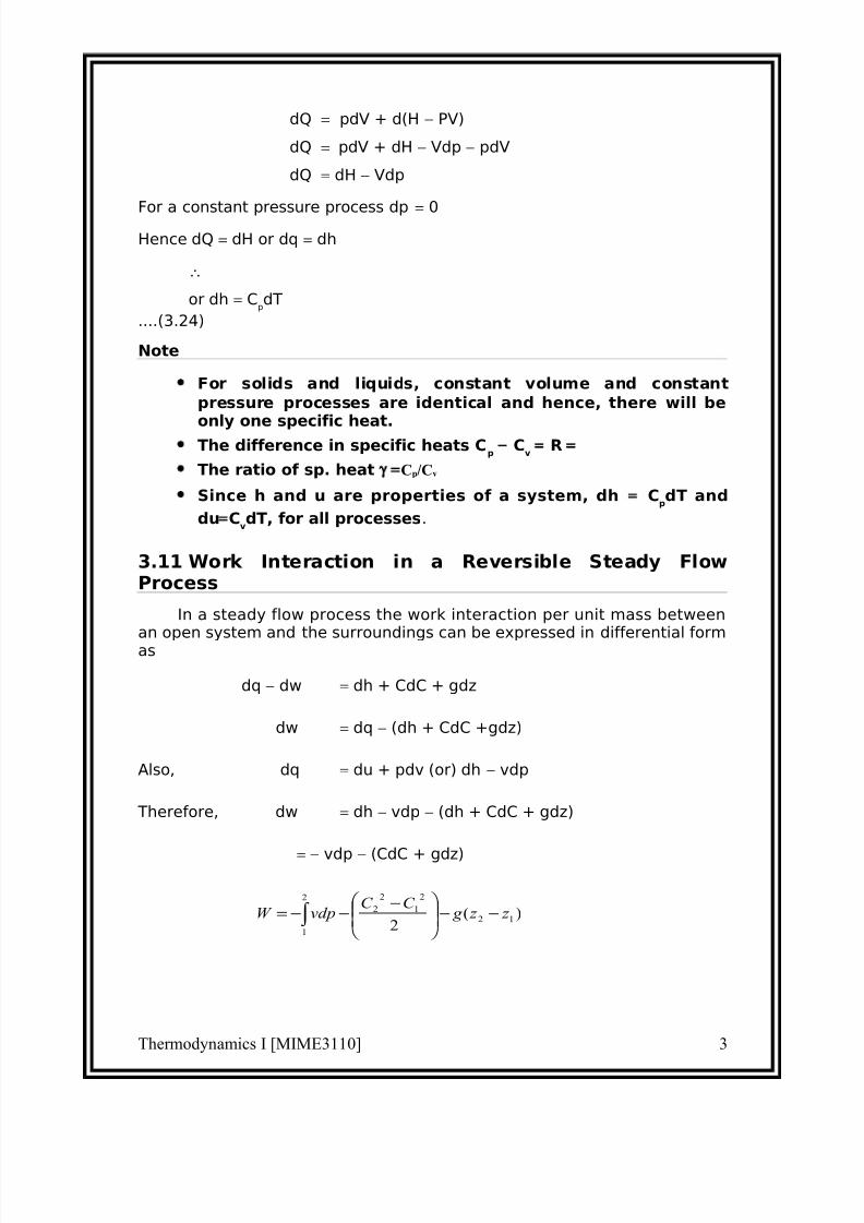
dQ = pdV + d(H − PV)
dQ = pdV + dH − Vdp − pdV
dQ = dH − Vdp
For a constant pressure process dp = 0Hence dQ = dH or dq = dh
∴
or dh = CpdT
....(3.24)
Note
• For solids and liquids, constant volume and constant
pressure processes are identical and hence, there will be
only one specific heat.• The difference in specific heats C
p − C
v = R =
• The ratio of sp. heat γ =Cp/Cv
• Since h and u are properties of a system, dh = CpdT and
du=CvdT, for all processes.
3.11 Work Interaction in a Reversible Steady FlowProcess
In a steady flow process the work interaction per unit mass betweenan open system and the surroundings can be expressed in differential formas
dq − dw = dh + CdC + gdz
dw = dq − (dh + CdC +gdz)
Also, dq = du + pdv (or) dh − vdp
Therefore, dw = dh − vdp − (dh + CdC + gdz)
= − vdp − (CdC + gdz)
Thermodynamics I [MIME3110] 3
)(2
12
2
1
2
2
2
1
z z g C C
vdpW −−
−−−= ∫
7/30/2019 Chapter 3-thermodynamics final.doc
http://slidepdf.com/reader/full/chapter-3-thermodynamics-finaldoc 19/26
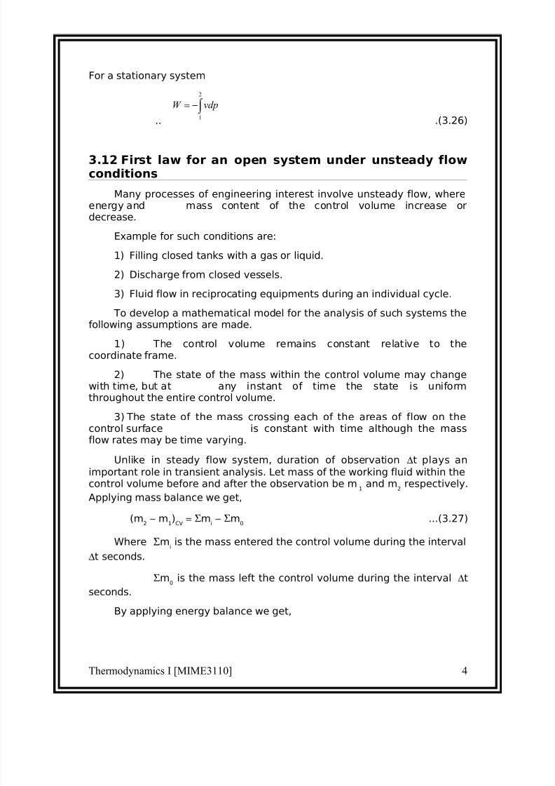
For a stationary system
.. .(3.26)
3.12 First law for an open system under unsteady flowconditions
Many processes of engineering interest involve unsteady flow, whereenergy and mass content of the control volume increase ordecrease.
Example for such conditions are:
1) Filling closed tanks with a gas or liquid.
2) Discharge from closed vessels.
3) Fluid flow in reciprocating equipments during an individual cycle.
To develop a mathematical model for the analysis of such systems thefollowing assumptions are made.
1) The control volume remains constant relative to thecoordinate frame.
2) The state of the mass within the control volume may changewith time, but at any instant of time the state is uniformthroughout the entire control volume.
3) The state of the mass crossing each of the areas of flow on thecontrol surface is constant with time although the massflow rates may be time varying.
Unlike in steady flow system, duration of observation ∆t plays an
important role in transient analysis. Let mass of the working fluid within thecontrol volume before and after the observation be m
1and m
2respectively.
Applying mass balance we get,
(m2 − m
1)
CV = Σm
i − Σm
0...(3.27)
Where Σmiis the mass entered the control volume during the interval
∆t seconds.
Σm0
is the mass left the control volume during the interval ∆t
seconds.
By applying energy balance we get,
Thermodynamics I [MIME3110] 4
∫ −=2
1
vdpW
7/30/2019 Chapter 3-thermodynamics final.doc
http://slidepdf.com/reader/full/chapter-3-thermodynamics-finaldoc 20/26
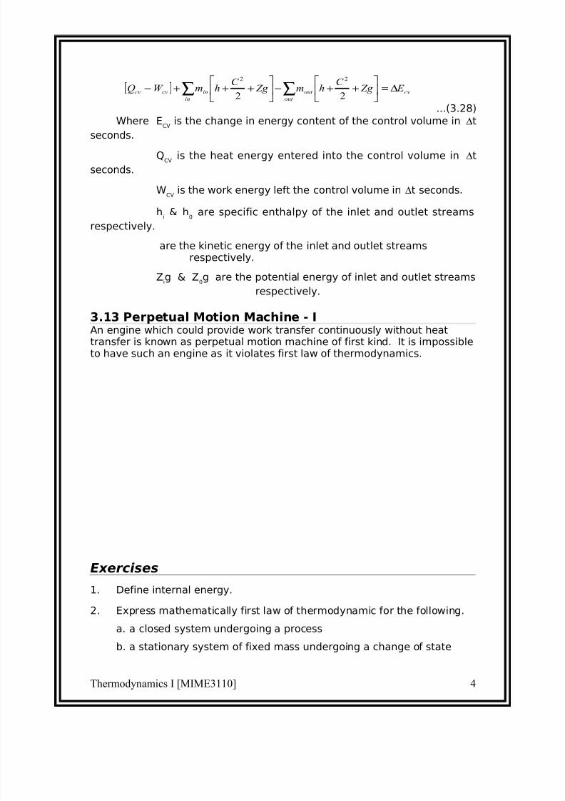
...(3.28)
Where ECV
is the change in energy content of the control volume in ∆t
seconds.Q
CVis the heat energy entered into the control volume in ∆t
seconds.
WCV
is the work energy left the control volume in ∆t seconds.
hi
& h0
are specific enthalpy of the inlet and outlet streams
respectively.
are the kinetic energy of the inlet and outlet streamsrespectively.
Zig & Z0g are the potential energy of inlet and outlet streamsrespectively.
3.13 Perpetual Motion Machine - IAn engine which could provide work transfer continuously without heattransfer is known as perpetual motion machine of first kind. It is impossibleto have such an engine as it violates first law of thermodynamics.
Exercises
1. Define internal energy.
2. Express mathematically first law of thermodynamic for the following.
a. a closed system undergoing a process
b. a stationary system of fixed mass undergoing a change of state
Thermodynamics I [MIME3110] 4
[ ] cv
out
out
in
incvcv E Zg C
hm Zg C
hmW Q ∆=
++−
+++− ∑∑
22
22
7/30/2019 Chapter 3-thermodynamics final.doc
http://slidepdf.com/reader/full/chapter-3-thermodynamics-finaldoc 21/26
c. a closed system undergoing a cycle.
d. an open system.
e. an open system with steady-state flow conditions.
3. Define flow energy and enthalpy.
4. For a stationary system of fixed mass undergoing a process such that
its volume remains constant,
Q12 = ∆U(T/F)
5. dQ = dh − vdp for closed system undergoing a process (T/F).
6. Define specific heat at (a) constant pressure (b) constant
volume
7. Determine the power of the cycle comprising four processes in which
the heat transfers are : 50 kJ/kg, −20 kJ/kg, −7l J/kg and 12 kJ/kg
having 100 cycles per minute.
[48.3 kW]
8. Write the steady flow energy equation and explain the terms involved
in it.
9. Show that energy is a property of the system.
10. What are conditions for steady flow process?
11. A piston-cylinder assembly contains 1kg or nitrogen at 100 kPa. The
initial volume is 0.5 m3. Heat is transferred to the substance in an
amount necessary to cause a slow expansion at constant
temperature. This process is terminated when the final volume is
twice the initial volume.
[34.7 kJ]
12. 2 kg of air enclosed in a rigid container receives 0.2 kJ of paddle wheel
work and 0.5 kJ of electrical energy per second. Heat loss from the
system is 0.6 kJ/s. If the initial temperature is 25oC what will be the
temperature after 5 minutes?
[45.9oC]
13. A well insulated, frictionless piston-cylinder assembly contains 0.5 kg
of air initially at 75oC and 300 kPa. An electric - resistance heating
element inside the cylinder is energized and causes the air
temperature to reach 150oC. The pressure of the air is maintained
constant throughout the process. Determine the work for the process
and the amount of electrical work.
{Hint Qnet − Wnet = ∆U; Wnet=+Welectric}
Thermodynamics I [MIME3110] 4

7/30/2019 Chapter 3-thermodynamics final.doc
http://slidepdf.com/reader/full/chapter-3-thermodynamics-finaldoc 22/26
[−26.9 kJ ; − 37.7]
14. A cylinder contains 168 litres of a gas at a pressure of 1 bar and
temperature of 47oC. If this gas is compressed to one-twelfth of its
volume, pressure is then 21 bar. Find
a. index of compression
b. change in internal energy
c. heat rejected during compression
Take Cp = 1.089 and Cv = 0.837 both in kJ/kg
[1.225 ; 41.81 kJ ; −14.05 kJ]
15. a. A mass of 10 kg is falling from a height of 100 m from the datum.
What will be the velocity when it reaches a height of 20 m from the
datum? Take the total heat loss from the mass when it falls from 100m height to 20 m height is 5 kJ.
[8.68 m/s]
b. An insulated box containing carbon dioxide gas falls from a balloon
3.5 km above the earths surface. Determine the temperature rise of
the carbon dioxide when box hits the ground.
Take Cv = 0.6556 kJ/kg
[52.37oC]
16. A working substance flows at a rate of 5 kg/s into a steady flow
system at 6 bar, 2000 kJ/kg of internal energy and 0.4 m3/kg specificvolume with a velocity of 300 m/s. It leaves at 10 bar, 1600 kJ/kg
internal energy, 1.2 m3/kg specific volume with a velocity of 150 m/s.
The inlet is 10m above the outlet. The work transfer to the
surroundings in 3 MW. Estimate the heat transfer and indicate the
direction.
[5630 kJ/s]
17. An air compressor takes in air at 100 kPa, 40oC and discharges it at
690 kPa, 208oC. The initial and final internal energy values for the air
are 224 and 346 kJ/kg respectively. The cooling water around the
cylinders removes 70 kJ/kg from the air. Neglecting changes in kineticand potential energy, calculate the work.
[100.216
kJ/kg]
18. A perfect gas of cp = 1.1 kJ/kg flows through a turbine at a rate of 3
kg/s. The inlet and exit velocity are 30 and 130 m/s respectively. The
Thermodynamics I [MIME3110] 4
7/30/2019 Chapter 3-thermodynamics final.doc
http://slidepdf.com/reader/full/chapter-3-thermodynamics-finaldoc 23/26
initial and final temperature are 650oC and 250
oC respectively. Heat
loss is 45 kJ/s. Find the power developed.
[1251
kW]
19. In a turbine 4500 kg/min of air expands polytropically from 425 kPa
and 1360 K to 101 kPa. The exponent n it equal to 1.45 for the
process. Find the work and heat.
[33939 kW ; −2927 kJ/s]
20. Air expands through a nozzle from a pressure of 500 kPa to a final
pressure of 100 kPa. The enthalpy decrease by 100 kJ/kg. The flow is
adiabatic and the inlet velocity is very low. Calculate the exit velocity.
[447.2 m/s]
21. A closed system undergoes a cycle consisting of three process 1-2, 2-3and 3-1. Given that Q12 = 30 kJ, Q23 = 10 kJ, 1w2 = 5 kJ, 3w2 = 5 kJ and
∆E31 = 15 kJ, determine Q31, w23, ∆E12 and ∆E23.
[20 kJ ; 50 kJ ; 25 kJ ; −40
kJ ]
22. The following cycle involves 3 kg of air : Polytropic compression from
1 to 2 where P1 = 150 kPa, T1 = 360 K, P2 = 750 kPa and n = 1.1 ;
constant-pressure cooling from 2 to 3; and constant - temperature
heating from 3 to 1. Draw the pV diagram and find temperatures,
pressures and volumes at each state and determine the net work and
heat.
[150 kPa ; 2.066 m3; 360 K ; 750 kPa ;
0.478 m3; 416.72 K ; 750
kPa ; 0.414 m3; 360 K ; −35 kJ]
23. A cycle, composed of three processes, is :
Polytropic compression (n = 1.5) from 137 kPa and 38oC to state 2 ;
constant pressure process from state 2 to state 3 ; constant volume
process form state 3 and to state 1. The heat rejected in process 3-1 is
1560 kJ/kg and the substance is air. Determine
(a) the pressures, temperatures and specific volumes around the
cycle
(b) the heat transfer in process 1-2
(c) the heat transfer in process 2-3
(d) work done in each process and
Thermodynamics I [MIME3110] 4
7/30/2019 Chapter 3-thermodynamics final.doc
http://slidepdf.com/reader/full/chapter-3-thermodynamics-finaldoc 24/26
(e) net work done in the cycle
[137 kPa ; 0.6515 m3/kg ; 311.0 K ; 1095 kPa ;
0.1630 m3/kg ; 621.8 K ; 1095 kPa ;
0.6515 m3/kg ; 2487.0 K ; 44.44 kJ ;
1872.25 kJ ; −178 kJ ; 534.9 kJ ; 0 ; 356.9 kJ]
24. 0.15 m3
of air at a pressure of 900 kPa and 300o
C is expanded at
constant pressure to 3 time its initial volume. It is then expanded
polytropically following the law PV 1.5
= C and finally compressed back
to initial state isothermally. Calculate
(a) heat received
(b) heat rejected
(c) efficiency of the cycle
[944.5kJ ; −224.906 kJ ; 0.291]
25. A piston and cylinder device contains 1 kg of air, Initially, v = 0.8 m3/kgand
T = 298 K. The air is compressed in a slow frictionless process to a
specific volume of 0.2 m3/kg and a temperature of 580 K according to
the equation pV 1.3
= 0.75 ( p in bar, v in m3/kg). If Cv of air is 0.78 kJ/kg
determine :
(a) work and
(b) heat transfer (both in kJ)
[ −137.85 kJ ; 82.11 kJ]
26. The internal energy of a closed system is given by U = 100 + 50 T +0.04 T
2in Joules, and the heat absorbed by Q = 4000 + 16 T in Joules,
where T is in Kelvin. If the system changes from 500 K to 1000 K, what
is the work done ?
[47 kJ]
27. One kg of air, volume 0.05 m3, pressure 20 bar expands reversibly
according to the law pv1.3
= C until the volume is doubled. It is then
cooled at constant pressure to initial volume and further heat atconstant volume so that it returns back to initial process. Calculate thenetwork done by air.
[21.98 kJ]
28. Air at the rate of 14 kg/s expands from 3 bar, 150°C to 1bar
reversibly and adiabatically. Find the exit temperature andpower developed. Neglect the changes in kinetic andpotential energy. [ 309 k ; 1.603 kW]
Thermodynamics I [MIME3110] 4
7/30/2019 Chapter 3-thermodynamics final.doc
http://slidepdf.com/reader/full/chapter-3-thermodynamics-finaldoc 25/26
29. Specific internal energy of a certain substance can be expressed asfollows:
u = 831.0 + 0.617 pv
Where u is the specific internal energy in kJ/kg
p is the pressure in k Pa
v is the specific volume in m3/kg
One kg of such substance expands from 850 kPa, 0.25 m 3/kg to 600kPa, 0.5 m3 /kg. Find the work done and heattransferred. [ 176.06 kJ ; 230 kJ]
30. A cylinder of 8 cm internal diameter is fitted with a piston loaded bya coil spring of stiffness 140 N/cm of compression. The cylinder
contains 0.0005 m3 of air at 15°C and 3 bar. Find the amount of
heat which must be supplied for the piston to a distance of 4cm. Sketch the process on a p-V diagram.
[ 0.417 kJ]
31. Prove that
Q = mCv
for a polytropic process of index n.
32. An air conditioning system for a computer room in a tower block drawsin air on the roof at a height of 100 m with a velocity of 25 m/s. The air
is at 28oC. The air is discharged at a height of 10 m with a velocity of 2
m/s at 14oC. The mass flow rate is 2 kg/s, and a heat transfer of −
40.73 kW cools the air before it is discharged. Calculate the rate of
work for the air passing through the system. Take Cp for air as 1005 J/kgK.
[− 10.23 kW]
33. A diffuser reduces the velocity of an air stream from 300 m/s to 30
m/s. If the inlet pressure and temperature are 1.01 bar and 315oC,
determine the outlet pressure. Find also the area required for thediffuser to pass a mass flow of 9 kg/s.
[4.586 bar, 0.17 m2]
34. A centrifugal air compressor operating at steady state has an airintake of 1.2 kg/min. Inlet and exit conditions are as follows:
Properties p (kPa) ToC u kJ/kg v m
3/kg
Inlet 100 0 195.14 0.784
Exit 200 50 230.99 0.464
If the heat loss is negligible, find the power input. [1.005 kW]
Thermodynamics I [MIME3110] 4

7/30/2019 Chapter 3-thermodynamics final.doc
http://slidepdf.com/reader/full/chapter-3-thermodynamics-finaldoc 26/26
35. A household gas cylinder initially evacuated is filled by 15 kg gas
supply of enthalpy 625 kJ/kg. After filling, the gas in the cylinder has
the following parameters :
pressure = 10 bar ;
enthalpy = 750 kJ/kg and
specific volume = 0.0487 m3/kg.
Evaluate the heat received by the cylinder from the surroundings.
[1144.5 kJ]
36. 0.56 m3
of air at 0.2 MPa is contained in a fully insulated rigid vessel.
The vessel communicates through a valve with a pipe line carrying
high pressure air at 300 K temperature. The valve is opened and the
air is allowed to flow into the tank until the pressure of air in the tank
is raised to 1MPa. Determine the mass of air that enters the tank.
Neglect kinetic energy of the incoming air.
[3.72 kg]37. An insulated rigid tank contains 8 kg of air at 1.5 bar pressure and 310
K temperature. It is filled with air from a large reservoir at 15 bar and
335 K. If the air behaves as a perfect gas, make calculations for the
amount of air added and its temperature.
[47.6 kg ; 446.04K]
38. A pressure vessel contains a gas at an initial pressure of 3.5 MN/m2
and at a temperature of 60oC. It is connected through a valve to a
vertical cylinder in which there is a piston. The valve is opened, gas
enters the vertical cylinder, and work is done in lifting the piston. The
valve is closed and the pressure and the temperature of the remaininggas in the cylinder are 1.7 MN/m
2and 25
oC, respectively. Determine
the temperature of the gas in the vertical cylinder if the process is
assumed to be adiabatic. Take γ = 1.4.
[267.6 K]
39. A pressure vessel is connected, via a valve, to a gas main in which a
gas is maintained at a constant pressure and temperature of 1.4
MN/m2
and 85oC, respectively. The pressure vessel is initially
evacuated. The valve is opened and a mass of 2.7 kg of gas passes
into the pressure vessel. The valve is closed and the pressure and
temperature of the gas in the pressure vessel are then 700 KN/m
2
and60
oC, respectively. Determine the heat transfer to or from the gas in
the vessel. Determine the volume of the vessel and the volume of the
gas before transfer.
For the gas, take Cp = 0.88 kJ/kgK, Cv = 0.67 . Neglect velocity of the
gas in the main
[−248.2 kJ ; 0.27 m3
;
0.145 m3
]