Embed Size (px)
Citation preview
Chapter 34: Electromagnetic Induction
Electro-magnetic Induction
34
Objectives 34-2
Summary of Learning Activities 34-3
Faraday’s Law of Induction 34-4 Motion between a magnetic pole and a conductor 34-4 Magnetic fields due to electric currents 34-6 Motion of a conductor in a magnetic field 34-8 Eddy Currents 34-12
Basic Electric Generators 34-15 Alternating current generators 34-15 Direct current generators 34-18
Alternating Current Energy sources 34-21
Generator and Motor Structures 34-23 Motor effect in generators 34-23 Back emf in motors 34-23 Generators 34-25 Alternating current motors 34-26 Direct current motors 34-29
Summary 34-33
Review Questions 34-35
Review Exercises 34-36
Practice Test 34-38
Answers to Exercises 34-39
Answers to Questions 34-39
Answers to Review Exercises 34-41
Answers to Practice Test 34-42
©John Betts Applied Physics All rights reserved.
34 - 1
Chapter 34: Electromagnetic Induction
Chapter 34 Electromagnetic Induction
Time-varying magnetic fields produce electric currents and potential differences by a process known as electromagnetic induction.
The American scientist Joseph Henry (1797-1878) was essentially self-educated, but did study at the Academy in Albany, New York. He taught at the Academy in Albany and then at the College of New Jersey (now Princeton). He was the first secretary of the Smithsonian Institution.
In 1831, about ten years after Hans Christian Oersted had observed that magnetic fields exist around an electric current, Joseph Henry and then Michael Faraday (independently a few months later) discovered the reverse effect. They found that time-varying magnetic fields produce electric currents and potential differences. This important discovery is known as electromagnetic induction.
Today we use electromagnetic induction in generators and transformers to produce and transmit essential electric power for our industries and households. Energy, often from a distance source, is converted into electric energy in generators, and transformers are used to modify that electric energy so that it can be efficiently transmitted to consumers.
In hydroelectric power plants the energies of large bodies of water, such as lakes and rivers, is converted into electric energy as the water is allowed to fall and deflect the blades of turbines. The thermal energy generated using other energy sources, such as nuclear energy and fossil fuels, produces mechanical energy in heat engines. In each case the rotational mechanical energy that is produced is converted into electric energy in a generator. Transformers are then used to modify the energy in order to reduce transmission losses and to make it acceptable for consumer use.
Objectives On completing this chapter, you should be able to:
• Define electromagnetic induction.
• Describe the production of an emf in a conductor that experiences time-varying magnetic fields.
• Use Faraday's law to solve problems.
• Describe the basic structures and operations of electric generators and motors.
Applied Physics ©John Betts All rights reserved.
34 - 2
Chapter 34: Electromagnetic Induction
• Describe the structures and operations of alternating current generators and motors.
• Describe, draw the circuit diagrams and solve problems involving direct current motors.
• Analyze the motor effect in generators and the generator effect in motors.
• Solve problems involving the frequency of the output from rotating field generators.
Summary of Learning Activities
• Read the material provided in this chapter.
• Learn to describe the production of an emf and current by electromagnetic induction and to apply Lenz's law to determine the directions of induced currents.
• Practice solving problems using Faraday's law.
• Learn to describe the basic structures and operations of ac generators.
• Learn to describe the motor effect in generators and the generator effect in motors.
• Learn to describe the different types of AC motors.
• Practice solving problems in involving the angular velocity of ac motors.
• Learn the circuit diagrams for dc motors.
• Cover the solutions to examples and try to solve them without looking. If you have difficulty, study the answer and then try to solve it by yourself once more.
• Try to write a one-page summary of the important points.
• Complete a sufficient number of the exercises provided at the end of each section until you have attained mastery of all the material. Be sure to contact your course tutor if you have difficulty with any section of this material.
• Answer all questions at the end of this module. Check to see if your answers are correct. If incorrect, review the appropriate materials and/or contact your tutor.
• Complete all of the review exercises.
• Complete the Practice Test and review the answers.
• Review the material relating to any questions that you did not answer correctly.
©John Betts Applied Physics All rights reserved.
34 - 3
Chapter 34: Electromagnetic Induction
Faraday’s Law of Induction An electric current and an electromotive force are induced in a conductor only when it experiences a time-varying magnetic field.
Joseph Henry was the first to discover electromagnetic induction, but Michael Faraday observed the same effect independently shortly after and also completed an experimental analysis of the phenomenon. Faraday determined that an electric current and an electromotive force are induced in a conductor when it experiences a time-varying magnetic field. There is no induced current or emf when the magnetic field remains constant.
Faraday completed several experiments to investigate electromagnetic induction, and from the results he derived the basic equation that describes the phenomenon. We shall only consider a sample of his investigations.
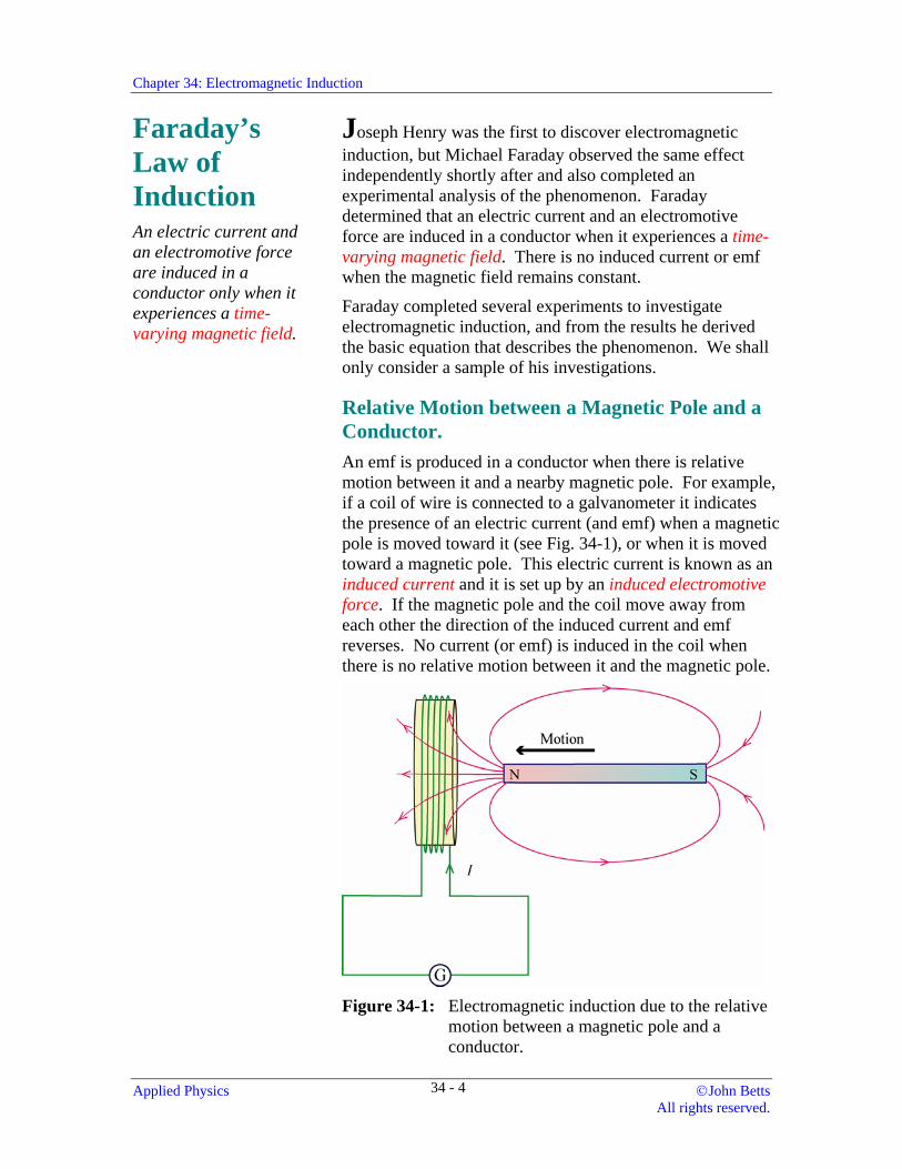
Relative Motion between a Magnetic Pole and a Conductor. An emf is produced in a conductor when there is relative motion between it and a nearby magnetic pole. For example, if a coil of wire is connected to a galvanometer it indicates the presence of an electric current (and emf) when a magnetic pole is moved toward it (see Fig. 34-1), or when it is moved toward a magnetic pole. This electric current is known as an induced current and it is set up by an induced electromotive force. If the magnetic pole and the coil move away from each other the direction of the induced current and emf reverses. No current (or emf) is induced in the coil when there is no relative motion between it and the magnetic pole.
Figure 34-1: Electromagnetic induction due to the relative
motion between a magnetic pole and a conductor.
Applied Physics ©John Betts All rights reserved.
34 - 4
Chapter 34: Electromagnetic Induction
Lenz's law states that the induced emf produces an induced electric current that sets up a magnetic field to oppose the change in the magnetic flux.
The direction of the induced emf and electric current may be determined from a law proposed by Heinrich Lenz (1804-1865).
Lenz's law states that the induced emf produces an induced electric current that it sets up a magnetic field to oppose the change in the magnetic flux.
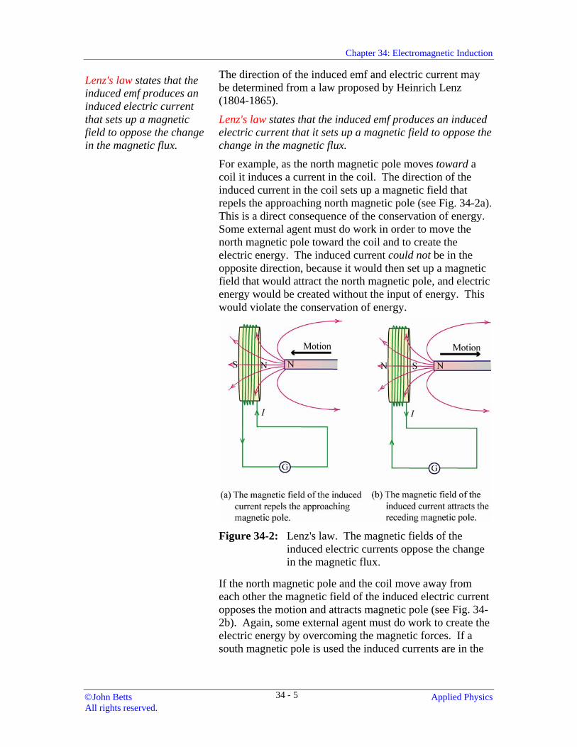
For example, as the north magnetic pole moves toward a coil it induces a current in the coil. The direction of the induced current in the coil sets up a magnetic field that repels the approaching north magnetic pole (see Fig. 34-2a). This is a direct consequence of the conservation of energy. Some external agent must do work in order to move the north magnetic pole toward the coil and to create the electric energy. The induced current could not be in the opposite direction, because it would then set up a magnetic field that would attract the north magnetic pole, and electric energy would be created without the input of energy. This would violate the conservation of energy.
Figure 34-2: Lenz's law. The magnetic fields of the
induced electric currents oppose the change in the magnetic flux.
If the north magnetic pole and the coil move away from each other the magnetic field of the induced electric current opposes the motion and attracts magnetic pole (see Fig. 34-2b). Again, some external agent must do work to create the electric energy by overcoming the magnetic forces. If a south magnetic pole is used the induced currents are in the
©John Betts Applied Physics All rights reserved.
34 - 5
Chapter 34: Electromagnetic Induction
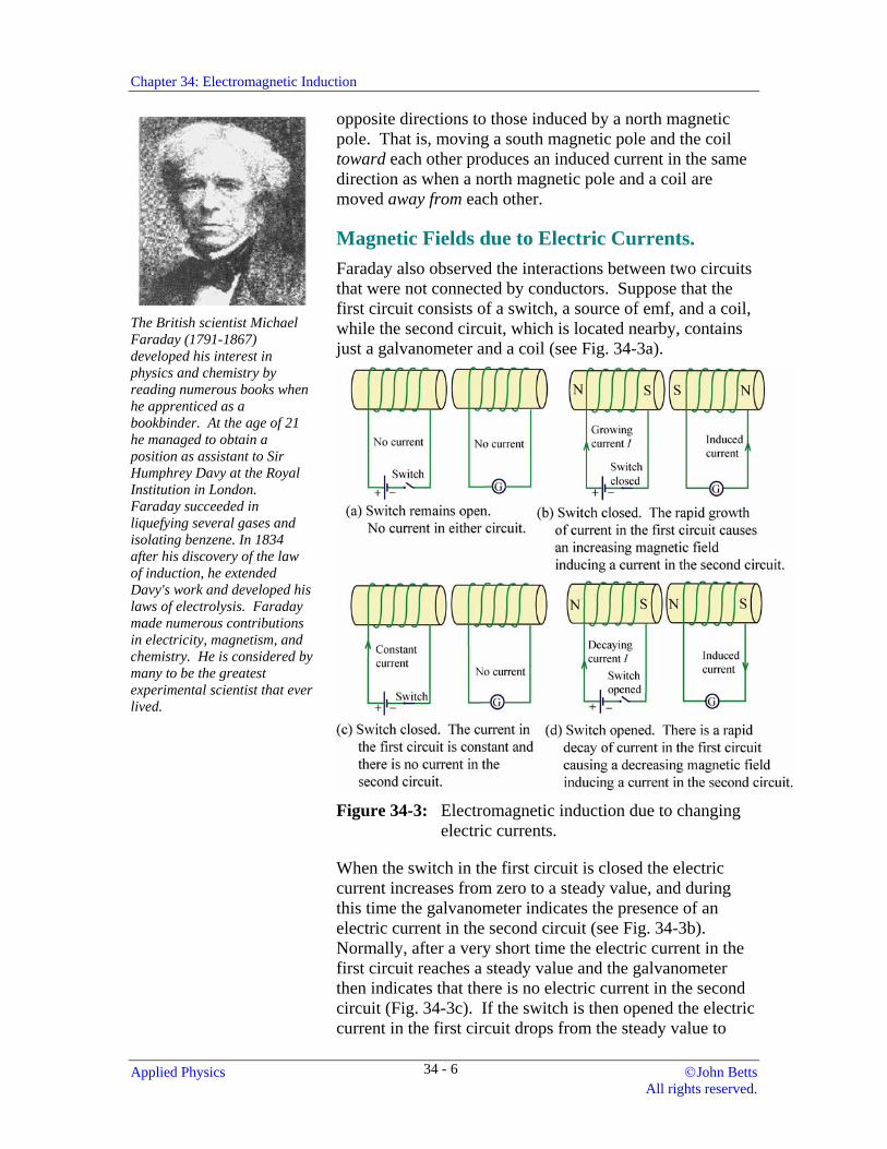
The British scientist Michael Faraday (1791-1867) developed his interest in physics and chemistry by reading numerous books when he apprenticed as a bookbinder. At the age of 21 he managed to obtain a position as assistant to Sir Humphrey Davy at the Royal Institution in London. Faraday succeeded in liquefying several gases and isolating benzene. In 1834 after his discovery of the law of induction, he extended Davy's work and developed his laws of electrolysis. Faraday made numerous contributions in electricity, magnetism, and chemistry. He is considered by many to be the greatest experimental scientist that ever lived.
opposite directions to those induced by a north magnetic pole. That is, moving a south magnetic pole and the coil toward each other produces an induced current in the same direction as when a north magnetic pole and a coil are moved away from each other.
Magnetic Fields due to Electric Currents. Faraday also observed the interactions between two circuits that were not connected by conductors. Suppose that the first circuit consists of a switch, a source of emf, and a coil, while the second circuit, which is located nearby, contains just a galvanometer and a coil (see Fig. 34-3a).
Figure 34-3: Electromagnetic induction due to changing
electric currents.
When the switch in the first circuit is closed the electric current increases from zero to a steady value, and during this time the galvanometer indicates the presence of an electric current in the second circuit (see Fig. 34-3b). Normally, after a very short time the electric current in the first circuit reaches a steady value and the galvanometer then indicates that there is no electric current in the second circuit (Fig. 34-3c). If the switch is then opened the electric current in the first circuit drops from the steady value to
Applied Physics ©John Betts All rights reserved.
34 - 6
Chapter 34: Electromagnetic Induction
zero. During the time while the current in the first circuit is decreasing the galvanometer indicates that there is a current in the second circuit once more (Fig. 34-3d). However, the current in the second circuit is in the opposite direction to the current that was present when the switch was closed and the current in the first circuit increased.
Lenz's law again gives the direction of the induced electric currents. For example, in Fig. 34-3b, when the switch is closed the magnetic field and the electric current in the first circuit increases in the direction given by the right hand rule. The magnetic field of the induced current in the second circuit must oppose this increasing magnetic field; therefore, the induced current sets up a magnetic field in the opposite direction. The direction of the induced electric current may then be determined from the right hand rule. When the switch is opened the magnetic field and the electric current are still in the same direction in the first circuit, but they are decreasing. The magnetic field of the induced current in the second circuit must oppose this decrease; therefore, the induced current sets up a magnetic field in the same direction as the magnetic field due to the current in the first circuit.
Faraday's law states that the induced emf E in a circuit is equal to the negative time rate of change of magnetic flux through the circuit:
E = −∆Φ∆t
If the circuit has N turns:
E = − FHGIKJ = −N
tNt
∆Φ∆
∆ Φ∆
( )
The flux linkage in the circuit = NΦ
After analyzing his observations Faraday proposed a law that describes the production of an induced emf. Faraday's law states that the induced emf E in a circuit is equal to the negative time rate of change of magnetic flux through the circuit. Therefore, if the magnetic flux changes by an amount ∆Φ in an elapsed time ∆t:
E = −∆Φ∆t
(34-1)
The negative sign is due to Lenz's law. It implies that the induced emf opposes the change that caused it. If the circuit has a constant N turns Faraday's law1 becomes:
E = − FHGIKJ = −N
tNt
∆Φ∆
∆ Φ∆
( ) (34-2)
The product of the number of turns and the magnetic flux is known as the flux linkage in the circuit.
Flux linkage = NΦ (34−3)
1 More precisely, this should be written as a derivative using calculus:
E = −Nddt
φ
©John Betts Applied Physics All rights reserved.
34 - 7
Chapter 34: Electromagnetic Induction
The flux linkage and induced emf may also be changed by altering the shape of a circuit.
Example 34-1 Determine the emf that is induced in a flat circular coil in air that has a radius of 3.75 cm and 25 turns if it is located with its axis parallel to the magnetic field where the magnetic induction changes at a rate of 42.5 T/s.
Solution
r = 3.75 cm, N = 25, ∆∆Bt
= 42 5. T / s
The area of the coil: , and since the axis is parallel A r= π 2
to the magnetic field, the magnetic flux density:
Φ = =BA B rπ 2
Therefore, from Equation 34-2, the induced emf:
E = − = − = − FHGIKJ
= − −
∆ Φ∆
∆∆
∆∆
( ) ( )
( ) ( . ( . .
Nt
NB rt
N r Bt
π π
π
22
25 0 0375 42 5 4 69 m) T / s) = V2
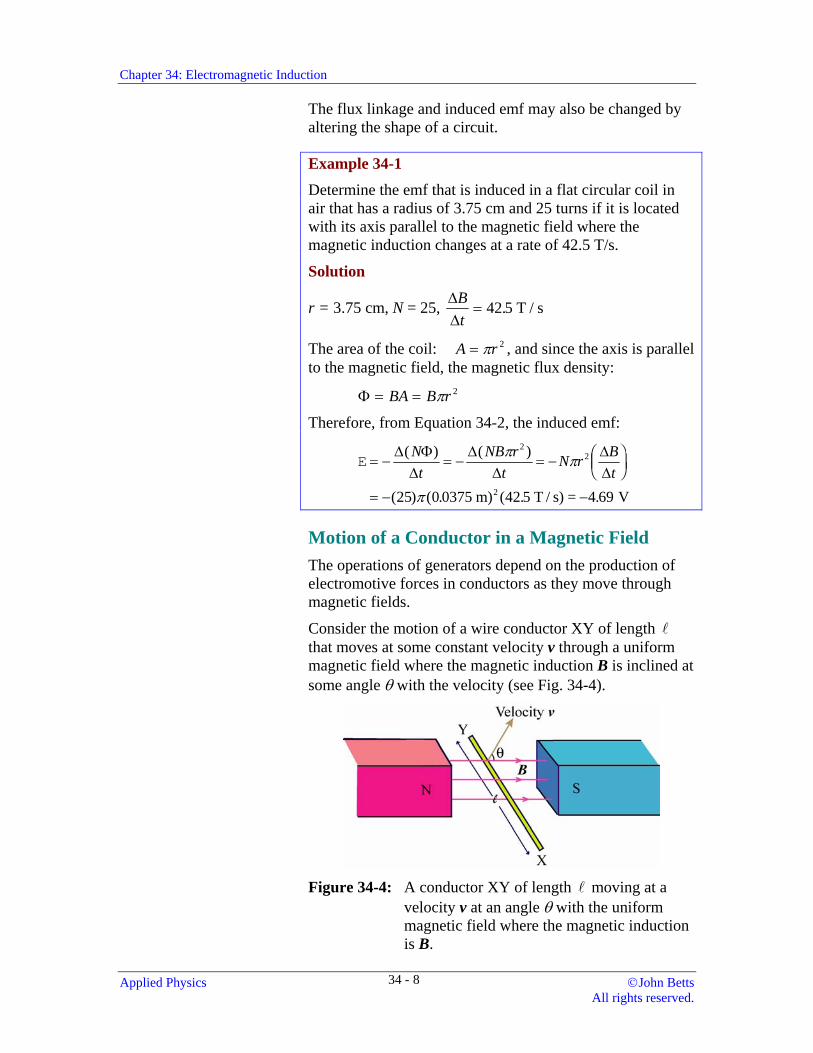
Motion of a Conductor in a Magnetic Field The operations of generators depend on the production of electromotive forces in conductors as they move through magnetic fields.
Consider the motion of a wire conductor XY of length that moves at some constant velocity v through a uniform magnetic field where the magnetic induction B is inclined at some angle θ with the velocity (see Fig. 34-4).
Figure 34-4: A conductor XY of length moving at a
velocity v at an angle θ with the uniform magnetic field where the magnetic induction is B.
Applied Physics ©John Betts All rights reserved.
34 - 8
Chapter 34: Electromagnetic Induction
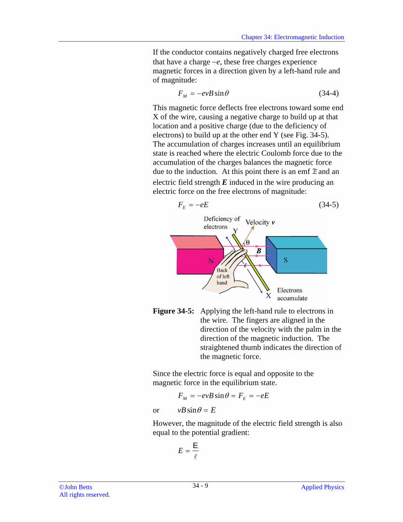
If the conductor contains negatively charged free electrons that have a charge −e, these free charges experience magnetic forces in a direction given by a left-hand rule and of magnitude:
F evBM = − sinθ (34-4)
This magnetic force deflects free electrons toward some end X of the wire, causing a negative charge to build up at that location and a positive charge (due to the deficiency of electrons) to build up at the other end Y (see Fig. 34-5). The accumulation of charges increases until an equilibrium state is reached where the electric Coulomb force due to the accumulation of the charges balances the magnetic force due to the induction. At this point there is an emf E and an electric field strength E induced in the wire producing an electric force on the free electrons of magnitude:
F eE E= − (34-5)
Figure 34-5: Applying the left-hand rule to electrons in
the wire. The fingers are aligned in the direction of the velocity with the palm in the direction of the magnetic induction. The straightened thumb indicates the direction of the magnetic force.
Since the electric force is equal and opposite to the magnetic force in the equilibrium state. F evB F eEM E= − = = −sinθ
or vB Esinθ =
However, the magnitude of the electric field strength is also equal to the potential gradient:
E =E
©John Betts Applied Physics All rights reserved.
34 - 9
Chapter 34: Electromagnetic Induction The emf induced in a length of a conductor that moves at a speed v and an angle θ with a magnetic field where the magnetic induction is B:
E = v B sinθ
The right hand rule: Align the fingers of the right hand in the direction of the velocity with the palm facing the direction of the magnetic induction and the straightened thumb gives the direction of the conventional electric current in the conductor.
Therefore, the induced emf (potential difference) between the ends of the conductor:
E = v B sinθ (34-6)
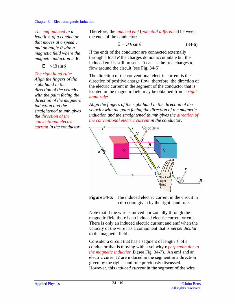
If the ends of the conductor are connected externally through a load R the charges do not accumulate but the induced emf is still present. It causes the free charges to flow around the circuit (see Fig. 34-6).
The direction of the conventional electric current is the direction of positive charge flow; therefore, the direction of the electric current in the segment of the conductor that is located in the magnetic field may be obtained from a right hand rule:
Align the fingers of the right hand in the direction of the velocity with the palm facing the direction of the magnetic induction and the straightened thumb gives the direction of the conventional electric current in the conductor.
Figure 34-6: The induced electric current in the circuit in
a direction given by the right hand rule.
Note that if the wire is moved horizontally through the magnetic field there is no induced electric current or emf. There is only an induced electric current and emf when the velocity of the wire has a component that is perpendicular to the magnetic field.
Consider a circuit that has a segment of length of a conductor that is moving with a velocity v perpendicular to the magnetic induction B (see Fig. 34-7). An emf and an electric current I are induced in the segment in a direction given by the right-hand rule previously discussed. However, this induced current in the segment of the wire
Applied Physics ©John Betts All rights reserved.
34 - 10
Chapter 34: Electromagnetic Induction
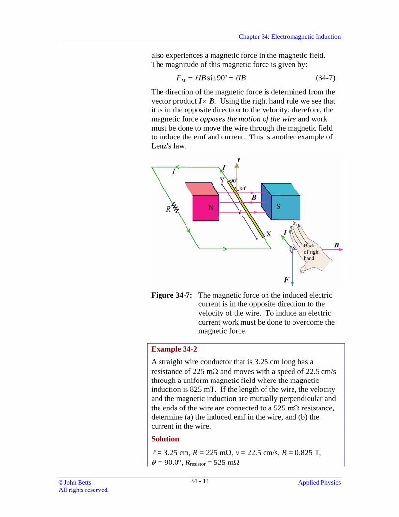
also experiences a magnetic force in the magnetic field. The magnitude of this magnetic force is given by:
F IB IM B= ° =sin 90 (34-7)
The direction of the magnetic force is determined from the vector product I × B. Using the right hand rule we see that it is in the opposite direction to the velocity; therefore, the magnetic force opposes the motion of the wire and work must be done to move the wire through the magnetic field to induce the emf and current. This is another example of Lenz's law.
Figure 34-7: The magnetic force on the induced electric
current is in the opposite direction to the velocity of the wire. To induce an electric current work must be done to overcome the magnetic force.
Example 34-2
A straight wire conductor that is 3.25 cm long has a resistance of 225 mΩ and moves with a speed of 22.5 cm/s through a uniform magnetic field where the magnetic induction is 825 mT. If the length of the wire, the velocity and the magnetic induction are mutually perpendicular and the ends of the wire are connected to a 525 mΩ resistance, determine (a) the induced emf in the wire, and (b) the current in the wire.
Solution
= 3.25 cm, R = 225 mΩ, v = 22.5 cm/s, B = 0.825 T, θ = 90.0°, Rresistor = 525 mΩ
©John Betts Applied Physics All rights reserved.
34 - 11
Chapter 34: Electromagnetic Induction
(a) E = v B sinθ
= °
−
( .0 2253
m / s)(0.0325 m)(0.825 T) sin 90.0= 6.03 x 10 V
(a) IR R
=+
= =−
−E
resistor
x 10 V + 0.525
x 10 A6 030 225
8 043
3..
.Ω Ω
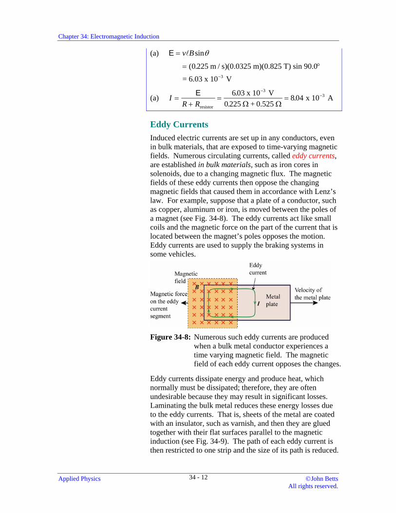
Eddy Currents Induced electric currents are set up in any conductors, even in bulk materials, that are exposed to time-varying magnetic fields. Numerous circulating currents, called eddy currents, are established in bulk materials, such as iron cores in solenoids, due to a changing magnetic flux. The magnetic fields of these eddy currents then oppose the changing magnetic fields that caused them in accordance with Lenz’s law. For example, suppose that a plate of a conductor, such as copper, aluminum or iron, is moved between the poles of a magnet (see Fig. 34-8). The eddy currents act like small coils and the magnetic force on the part of the current that is located between the magnet’s poles opposes the motion. Eddy currents are used to supply the braking systems in some vehicles.
Figure 34-8: Numerous such eddy currents are produced
when a bulk metal conductor experiences a time varying magnetic field. The magnetic field of each eddy current opposes the changes.
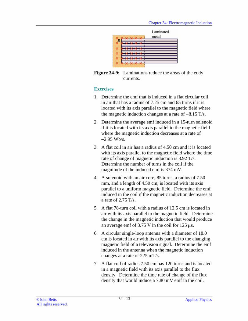
Eddy currents dissipate energy and produce heat, which normally must be dissipated; therefore, they are often undesirable because they may result in significant losses. Laminating the bulk metal reduces these energy losses due to the eddy currents. That is, sheets of the metal are coated with an insulator, such as varnish, and then they are glued together with their flat surfaces parallel to the magnetic induction (see Fig. 34-9). The path of each eddy current is then restricted to one strip and the size of its path is reduced.
Applied Physics ©John Betts All rights reserved.
34 - 12
Chapter 34: Electromagnetic Induction
Figure 34-9: Laminations reduce the areas of the eddy
currents.
Exercises 1. Determine the emf that is induced in a flat circular coil
in air that has a radius of 7.25 cm and 65 turns if it is located with its axis parallel to the magnetic field where the magnetic induction changes at a rate of −8.15 T/s.
2. Determine the average emf induced in a 15-turn solenoid if it is located with its axis parallel to the magnetic field where the magnetic induction decreases at a rate of −2.95 Wb/s.
3. A flat coil in air has a radius of 4.50 cm and it is located with its axis parallel to the magnetic field where the time rate of change of magnetic induction is 3.92 T/s. Determine the number of turns in the coil if the magnitude of the induced emf is 374 mV.
4. A solenoid with an air core, 85 turns, a radius of 7.50 mm, and a length of 4.50 cm, is located with its axis parallel to a uniform magnetic field. Determine the emf induced in the coil if the magnetic induction decreases at a rate of 2.75 T/s.
5. A flat 78-turn coil with a radius of 12.5 cm is located in air with its axis parallel to the magnetic field. Determine the change in the magnetic induction that would produce an average emf of 3.75 V in the coil for 125 µs.
6. A circular single-loop antenna with a diameter of 18.0 cm is located in air with its axis parallel to the changing magnetic field of a television signal. Determine the emf induced in the antenna when the magnetic induction changes at a rate of 225 mT/s.
7. A flat coil of radius 7.50 cm has 120 turns and is located in a magnetic field with its axis parallel to the flux density. Determine the time rate of change of the flux density that would induce a 7.80 mV emf in the coil.
©John Betts Applied Physics All rights reserved.
34 - 13
Chapter 34: Electromagnetic Induction
8. A long solenoid with an air core has 82 turns/cm with a radius of 1.20 cm, and it carries a current that changes at a rate of −15.2 A/s. A second solenoid with 325 turns of diameter of 7.25 mm is located in its centre with its axis parallel to the first solenoid. Determine the emf induced in the second solenoid.
9. In air a long solenoid has 250 turns/cm of radius 1.50 cm, and the current in it changes from 775 mA to 225 mA in 7.25 ms at a constant rate. A second solenoid with 1750 turns of radius 1.00 cm is located at the centre with its axis parallel to the first solenoid. Determine the emf induced in the second solenoid.
10. A straight wire conductor that is 4.50 cm long has a resistance of 375 mΩ and moves with a speed of 52.5 cm/s through a uniform magnetic field where the magnetic induction is 675 mT. If the length of the wire, the velocity and the magnetic induction are mutually perpendicular and the ends of the wire are connected to an 825 mΩ resistance, determine (a) the induced emf in the wire, and (b) the current in the wire.
11. A wire conductor has a length of 12.5 cm and it moves at a speed of 1.75 m/s through a magnetic field where the magnetic induction has a magnitude of 725 mT. Determine the emf induced in the wire (a) when its length, velocity and the magnetic induction are mutually perpendicular, and (b) when the length of the wire and the magnetic induction are perpendicular, but the velocity of the wire is inclined at 30.0° with the magnetic induction.
12. A conductor has a resistance of 275 mΩ, a length of 12.0 cm, and it moves with a speed of 2.75 m/s through a magnetic field where the magnetic induction has a magnitude of 1.15 T. If the length of the wire, the velocity and the magnetic induction are mutually perpendicular, determine (a) the induced emf in the wire, and (b) the electric field strength in the wire. (c) If the ends of the wire are connected to a 1.15 Ω resistance, what is the electric current in the wire?
13. Show that the power developed by the applied force in pulling a wire perpendicularly through a uniform magnetic field is equal to the time rate at which the thermal energy is dissipated in the conductor as it moves through that magnetic field.
Applied Physics ©John Betts All rights reserved.
34 - 14
Chapter 34: Electromagnetic Induction
Basic Electric Generators A basic ac generator or alternator consists of a tightly wound armature is mounted between the poles of a magnet so that it is free to rotate about an axis perpendicular to the magnetic induction. The ends of the armature are connected to circular-shaped metallic slip rings that slide over stationary graphite brushes making electric contact.
Faraday's law of electromagnetic induction is the principle that is used in devices called generators (or dynamos) to convert mechanical energy into electric energy. The electric current from direct current (dc) generators is always in the same direction, while the current from alternating current (ac) generators or alternators reverses direction periodically.
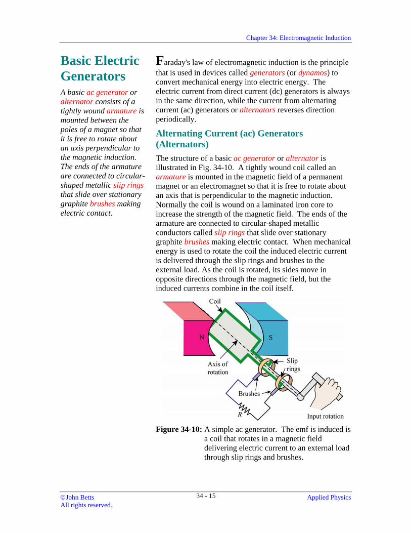
Alternating Current (ac) Generators (Alternators) The structure of a basic ac generator or alternator is illustrated in Fig. 34-10. A tightly wound coil called an armature is mounted in the magnetic field of a permanent magnet or an electromagnet so that it is free to rotate about an axis that is perpendicular to the magnetic induction. Normally the coil is wound on a laminated iron core to increase the strength of the magnetic field. The ends of the armature are connected to circular-shaped metallic conductors called slip rings that slide over stationary graphite brushes making electric contact. When mechanical energy is used to rotate the coil the induced electric current is delivered through the slip rings and brushes to the external load. As the coil is rotated, its sides move in opposite directions through the magnetic field, but the induced currents combine in the coil itself.
Figure 34-10: A simple ac generator. The emf is induced is
a coil that rotates in a magnetic field delivering electric current to an external load through slip rings and brushes.
©John Betts Applied Physics All rights reserved.
34 - 15
Chapter 34: Electromagnetic Induction
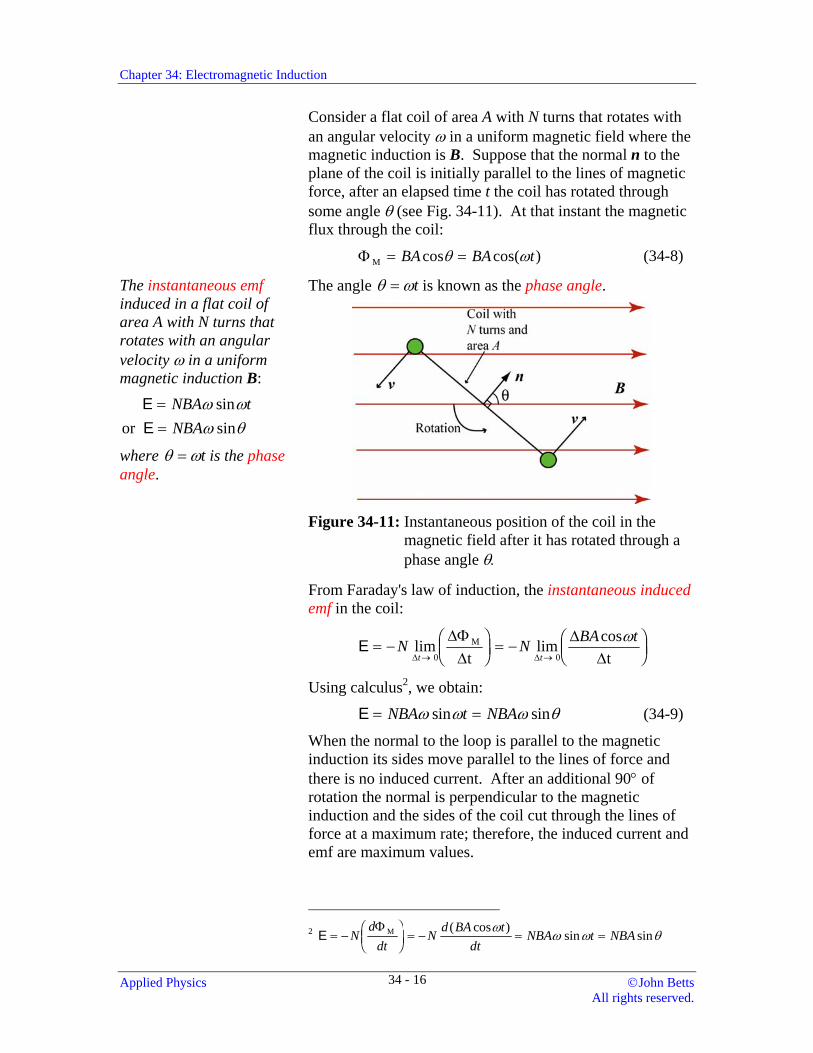
Consider a flat coil of area A with N turns that rotates with an angular velocity ω in a uniform magnetic field where the magnetic induction is B. Suppose that the normal n to the plane of the coil is initially parallel to the lines of magnetic force, after an elapsed time t the coil has rotated through some angle θ (see Fig. 34-11). At that instant the magnetic flux through the coil:
Φ M = =BA BA tcos cos( )θ ω (34-8)
The instantaneous emf induced in a flat coil of area A with N turns that rotates with an angular velocity ω in a uniform magnetic induction B: or
EE
==
NBA tNBA
ω ωω θ
sinsin
where θ ω= t is the phase angle.
The angle θ ω= t is known as the phase angle.
Figure 34-11: Instantaneous position of the coil in the
magnetic field after it has rotated through a phase angle θ.
From Faraday's law of induction, the instantaneous induced emf in the coil:
E = − FHGIKJ = − F
HGIKJ→ →
N N BA tt tlim lim cos∆ ∆
∆Φ∆
∆∆ 0
M
0t tω
Using calculus2, we obtain:
E = =NBA t NBAω ω ω θsin sin (34-9)
When the normal to the loop is parallel to the magnetic induction its sides move parallel to the lines of force and there is no induced current. After an additional 90° of rotation the normal is perpendicular to the magnetic induction and the sides of the coil cut through the lines of force at a maximum rate; therefore, the induced current and emf are maximum values.
2 E = −
FHGIKJ = − = =N
ddt
N d BA tdt
NBA t NBAΦ M ( cos ) sin sinω
ω ω θ
Applied Physics ©John Betts All rights reserved.
34 - 16
Chapter 34: Electromagnetic Induction
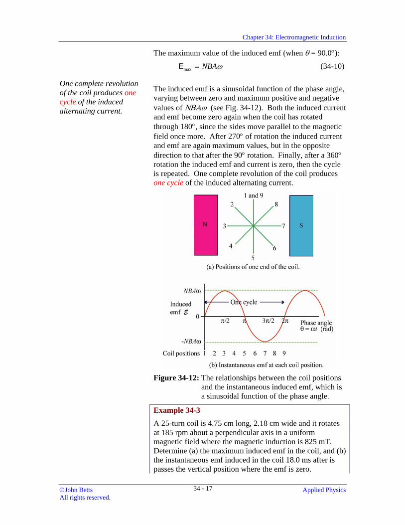
The maximum value of the induced emf (when θ = 90.0°):
Emax = NBAω (34-10)
One complete revolution of the coil produces one cycle of the induced alternating current.
The induced emf is a sinusoidal function of the phase angle, varying between zero and maximum positive and negative values of ΝΒΑω (see Fig. 34-12). Both the induced current and emf become zero again when the coil has rotated through 180°, since the sides move parallel to the magnetic field once more. After 270° of rotation the induced current and emf are again maximum values, but in the opposite direction to that after the 90° rotation. Finally, after a 360° rotation the induced emf and current is zero, then the cycle is repeated. One complete revolution of the coil produces one cycle of the induced alternating current.
Figure 34-12: The relationships between the coil positions
and the instantaneous induced emf, which is a sinusoidal function of the phase angle.
Example 34-3
A 25-turn coil is 4.75 cm long, 2.18 cm wide and it rotates at 185 rpm about a perpendicular axis in a uniform magnetic field where the magnetic induction is 825 mT. Determine (a) the maximum induced emf in the coil, and (b) the instantaneous emf induced in the coil 18.0 ms after is passes the vertical position where the emf is zero.
©John Betts Applied Physics All rights reserved.
34 - 17
Chapter 34: Electromagnetic Induction
Solution
N = 25, = 4.75 cm, w= 2.18 cm, ω = 185 rpm,
B = 825 mT, t = 18.0 ms
(a) Emax = NBAω
2(25)(0.825 T)(0.0475 m x 0.0218 m) 185 x rad/s60
0.414 V
π⎛ ⎞= ⎜ ⎟⎝ ⎠
=
(b) max185 x 2 radsin (0.414 V) sin (0.0180 s)
60 st πω
⎡ ⎤⎛ ⎞= = ⎜ ⎟⎢ ⎥⎝ ⎠⎣ ⎦
E E
0.141 V=
Note that the radians mode is used in this calculation.
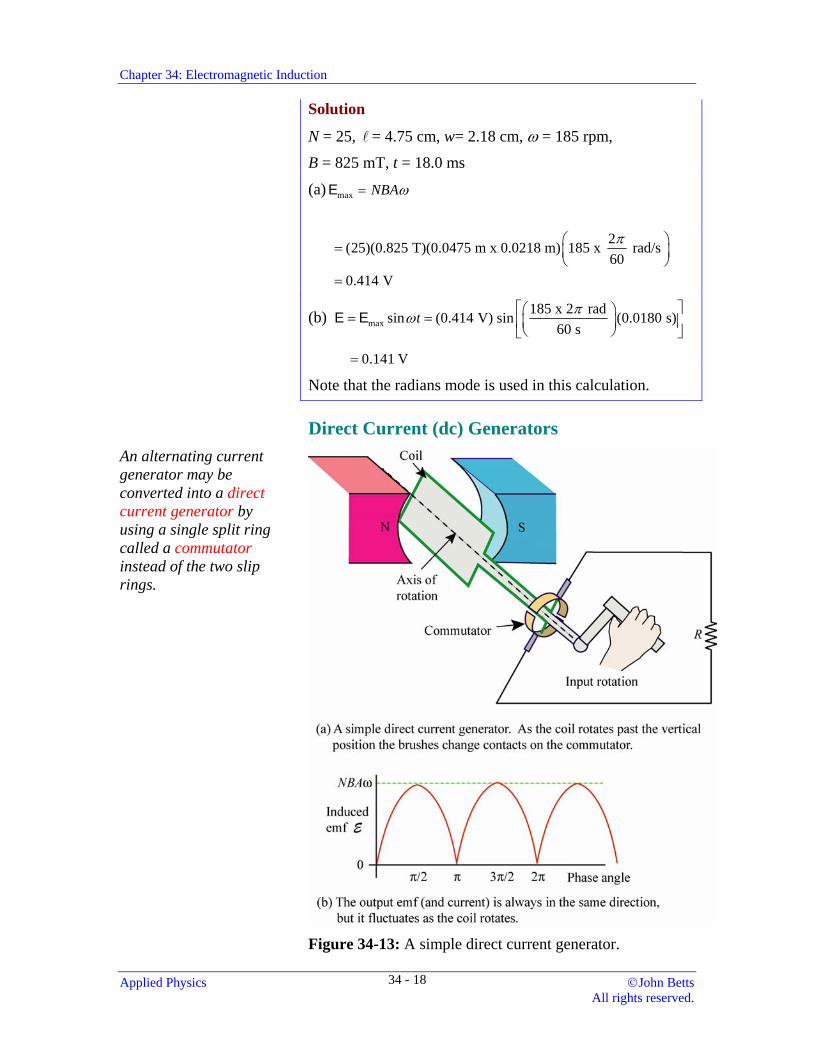
Direct Current (dc) Generators An alternating current generator may be converted into a direct current generator by using a single split ring called a commutator instead of the two slip rings.
Figure 34-13: A simple direct current generator.
Applied Physics ©John Betts All rights reserved.
34 - 18
Chapter 34: Electromagnetic Induction
An alternating current generator may be converted into a direct current generator by using a single split ring called a commutator instead of the two slip rings (see Fig. 34-13). Each end of the coil is connected to a different half of the commutator. As the coil rotates past the position where the normal to its surface is parallel to the magnetic induction the induced emf reverses direction, but at the same time the brushes change contacts to the other halves of the commutator. Therefore, the induced emf and the current fluctuate, but they are always in the same direction across the load (see Fig. 34-13b).
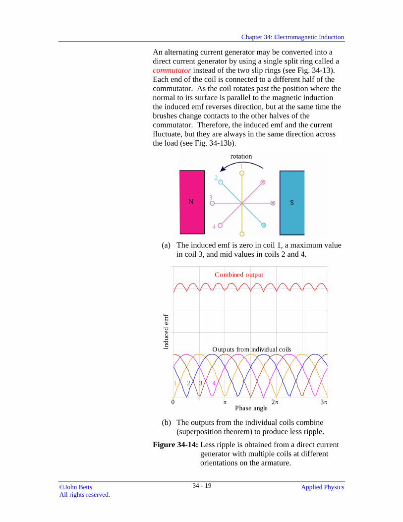
(a) The induced emf is zero in coil 1, a maximum value in coil 3, and mid values in coils 2 and 4.
Phase angle
Indu
ced
emf
Combined output
3π
1 2 3 4
0 π 2π
Outputs from individual coils
(b)
The outputs from the individual coils combine (superposition theorem) to produce less ripple.
Figure 34-14: Less ripple is obtained from a direct current generator with multiple coils at different orientations on the armature.
©John Betts Applied Physics All rights reserved.
34 - 19
Chapter 34: Electromagnetic Induction Fluctuations in the output emf and current are called ripple. It is reduced by using multiple coils wound with different orientations on the armature.
In order to reduce the fluctuations in the output emf and current, called ripple, most direct current generators are constructed with multiple coils that are wound at different orientations on the armature. The induced emf in the coil that has the normal to its area parallel to the magnetic field is zero when the emf induced in a perpendicular coil (with its normal perpendicular to the magnetic field) is a maximum. Therefore, the outputs from the different coils peak at different times. When they are combined (added) they produce a much steadier emf and current (see Fig. 34-14). In each coil the contact with the commutator changes as it passes through the vertical position so that the current is always in the same direction through the load.
Direct current generators are frequently used to charge batteries or banks of batteries and in applications where the load may be powered by batteries. The most common areas of application are in telecommunications equipment, uninterruptible power systems, and rectifier-powered systems. In operation the generator starts up automatically (without external switches) and powers the load when the potential difference of the battery bank drops below a specified level.
Exercises 14. A 65-turn coil is 3.75 cm long, 1.75 cm wide and it
rotates at 1750 rpm about a perpendicular axis in a uniform magnetic field where the magnetic induction is 625 mT. Determine (a) the maximum induced emf in the coil, and (b) the instantaneous emf induced in the coil 25.0 ms after is passes the vertical position where the emf is zero.
15. A 35-turn coil is 5.15 cm long, 2.25 cm wide and it rotates about a perpendicular axis in a uniform magnetic field where the magnetic induction is 825 mT. If the maximum emf induced in the coil is 6.25 V, determine its angular velocity in revolutions per minute.
16. A 115-turn coil is 4.25 cm long, 2.50 cm wide and it rotates at 2750 rpm about a perpendicular axis in a uniform magnetic field. If the maximum emf induced in the coil is 7.50 V, determine magnitude of the magnetic induction.
Applied Physics ©John Betts All rights reserved.
34 - 20
Chapter 34: Electromagnetic Induction
Alternating Current Energy Sources
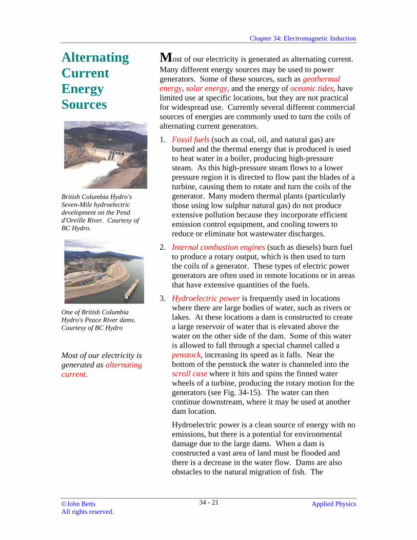
British Columbia Hydro's Seven-Mile hydroelectric development on the Pend d'Oreille River. Courtesy of BC Hydro.
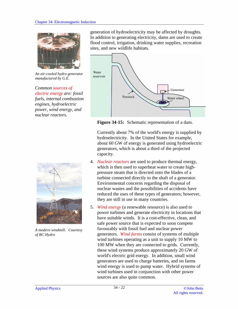
One of British Columbia Hydro's Peace River dams. Courtesy of BC Hydro Most of our electricity is generated as alternating current.
Most of our electricity is generated as alternating current. Many different energy sources may be used to power generators. Some of these sources, such as geothermal energy, solar energy, and the energy of oceanic tides, have limited use at specific locations, but they are not practical for widespread use. Currently several different commercial sources of energies are commonly used to turn the coils of alternating current generators.
1. Fossil fuels (such as coal, oil, and natural gas) are burned and the thermal energy that is produced is used to heat water in a boiler, producing high-pressure steam. As this high-pressure steam flows to a lower pressure region it is directed to flow past the blades of a turbine, causing them to rotate and turn the coils of the generator. Many modern thermal plants (particularly those using low sulphur natural gas) do not produce extensive pollution because they incorporate efficient emission control equipment, and cooling towers to reduce or eliminate hot wastewater discharges.
2. Internal combustion engines (such as diesels) burn fuel to produce a rotary output, which is then used to turn the coils of a generator. These types of electric power generators are often used in remote locations or in areas that have extensive quantities of the fuels.
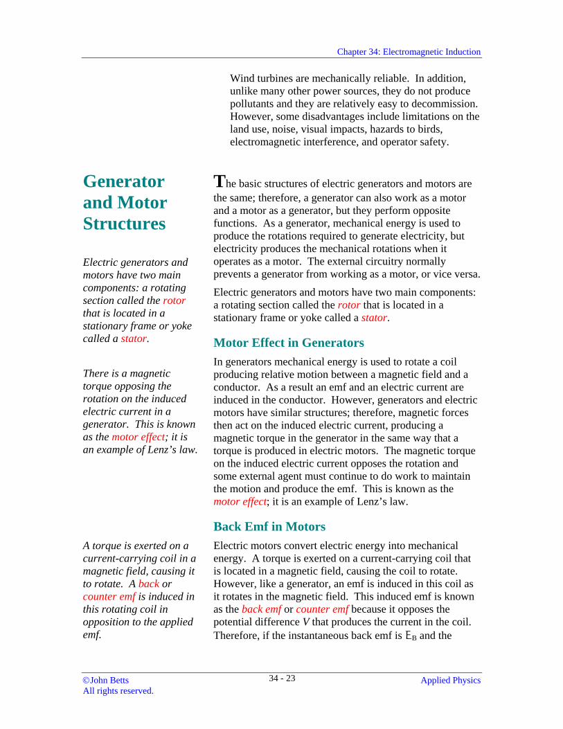
3. Hydroelectric power is frequently used in locations where there are large bodies of water, such as rivers or lakes. At these locations a dam is constructed to create a large reservoir of water that is elevated above the water on the other side of the dam. Some of this water is allowed to fall through a special channel called a penstock, increasing its speed as it falls. Near the bottom of the penstock the water is channeled into the scroll case where it hits and spins the finned water wheels of a turbine, producing the rotary motion for the generators (see Fig. 34-15). The water can then continue downstream, where it may be used at another dam location.
Hydroelectric power is a clean source of energy with no emissions, but there is a potential for environmental damage due to the large dams. When a dam is constructed a vast area of land must be flooded and there is a decrease in the water flow. Dams are also obstacles to the natural migration of fish. The
©John Betts Applied Physics All rights reserved.
34 - 21
Chapter 34: Electromagnetic Induction
An air-cooled hydro generator manufactured by G.E.
Common sources of electric energy are: fossil fuels, internal combustion engines, hydroelectric power, wind energy, and nuclear reactors.
generation of hydroelectricity may be affected by droughts. In addition to generating electricity, dams are used to create flood control, irrigation, drinking water supplies, recreation sites, and new wildlife habitats.
Figure 34-15: Schematic representation of a dam.
Currently about 7% of the world's energy is supplied by hydroelectricity. In the United States for example, about 60 GW of energy is generated using hydroelectric generators, which is about a third of the projected capacity.
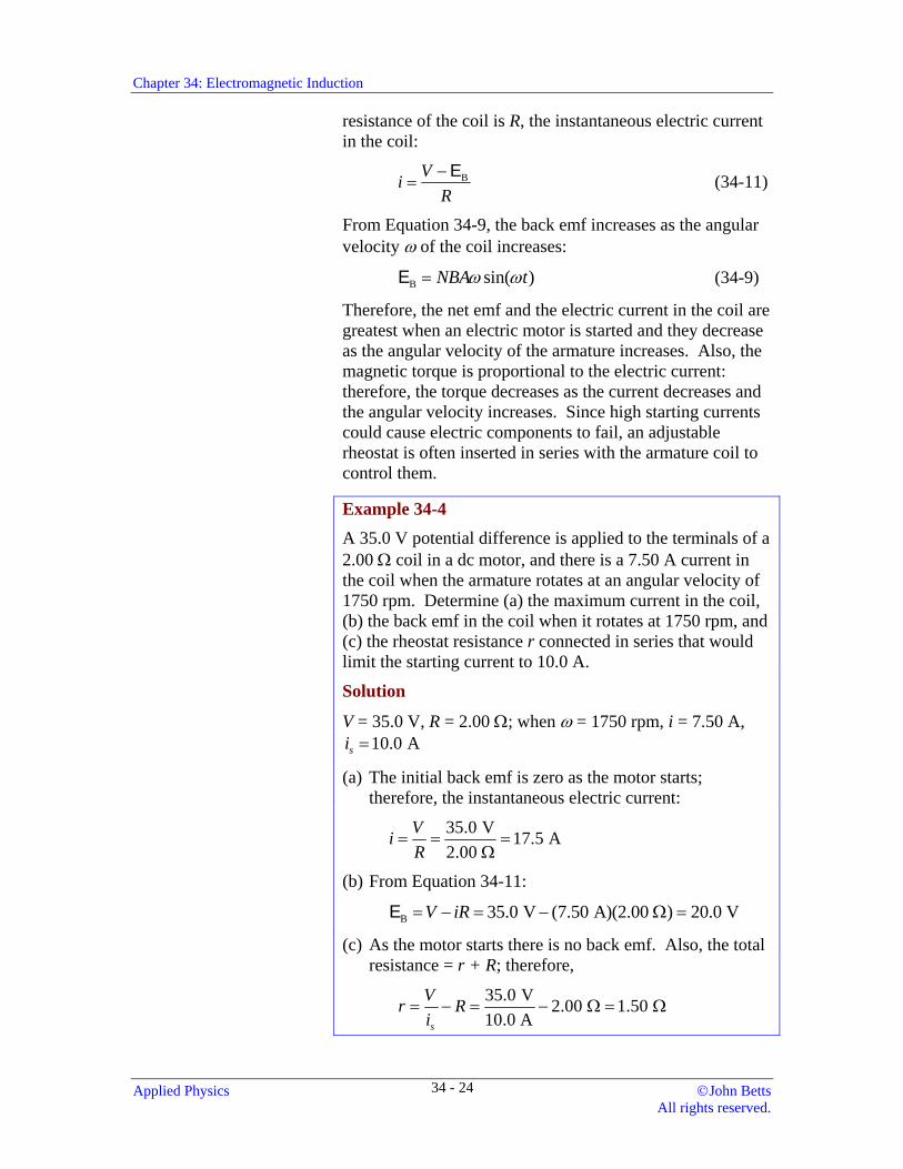
A modern windmill. Courtesy of BC Hydro
4. Nuclear reactors are used to produce thermal energy, which is then used to superheat water to create high-pressure steam that is directed onto the blades of a turbine connected directly to the shaft of a generator. Environmental concerns regarding the disposal of nuclear wastes and the possibilities of accidents have reduced the uses of these types of generators; however, they are still in use in many countries.
5. Wind energy (a renewable resource) is also used to power turbines and generate electricity in locations that have suitable winds. It is a cost-effective, clean, and safe power source that is expected to soon compete favourably with fossil fuel and nuclear power generators. Wind farms consist of systems of multiple wind turbines operating as a unit to supply 10 MW to 100 MW when they are connected to grids. Currently, these wind systems produce approximately 20 GW of world's electric grid energy. In addition, small wind generators are used to charge batteries, and on farms wind energy is used to pump water. Hybrid systems of wind turbines used in conjunction with other power sources are also quite common.
Applied Physics ©John Betts All rights reserved.
34 - 22
Chapter 34: Electromagnetic Induction
Wind turbines are mechanically reliable. In addition, unlike many other power sources, they do not produce pollutants and they are relatively easy to decommission. However, some disadvantages include limitations on the land use, noise, visual impacts, hazards to birds, electromagnetic interference, and operator safety.
Generator and Motor Structures
Electric generators and motors have two main components: a rotating section called the rotor that is located in a stationary frame or yoke called a stator.
There is a magnetic torque opposing the rotation on the induced electric current in a generator. This is known as the motor effect; it is an example of Lenz’s law.
The basic structures of electric generators and motors are the same; therefore, a generator can also work as a motor and a motor as a generator, but they perform opposite functions. As a generator, mechanical energy is used to produce the rotations required to generate electricity, but electricity produces the mechanical rotations when it operates as a motor. The external circuitry normally prevents a generator from working as a motor, or vice versa.
Electric generators and motors have two main components: a rotating section called the rotor that is located in a stationary frame or yoke called a stator.
Motor Effect in Generators In generators mechanical energy is used to rotate a coil producing relative motion between a magnetic field and a conductor. As a result an emf and an electric current are induced in the conductor. However, generators and electric motors have similar structures; therefore, magnetic forces then act on the induced electric current, producing a magnetic torque in the generator in the same way that a torque is produced in electric motors. The magnetic torque on the induced electric current opposes the rotation and some external agent must continue to do work to maintain the motion and produce the emf. This is known as the motor effect; it is an example of Lenz’s law.
Back Emf in Motors A torque is exerted on a current-carrying coil in a magnetic field, causing it to rotate. A back or counter emf is induced in this rotating coil in opposition to the applied emf.
Electric motors convert electric energy into mechanical energy. A torque is exerted on a current-carrying coil that is located in a magnetic field, causing the coil to rotate. However, like a generator, an emf is induced in this coil as it rotates in the magnetic field. This induced emf is known as the back emf or counter emf because it opposes the potential difference V that produces the current in the coil. Therefore, if the instantaneous back emf is EB and the
©John Betts Applied Physics All rights reserved.
34 - 23
Chapter 34: Electromagnetic Induction
resistance of the coil is R, the instantaneous electric current in the coil:
BViR−
=E (34-11)
From Equation 34-9, the back emf increases as the angular velocity ω of the coil increases:
B sin( )NBA tω ω=E (34-9)
Therefore, the net emf and the electric current in the coil are greatest when an electric motor is started and they decrease as the angular velocity of the armature increases. Also, the magnetic torque is proportional to the electric current: therefore, the torque decreases as the current decreases and the angular velocity increases. Since high starting currents could cause electric components to fail, an adjustable rheostat is often inserted in series with the armature coil to control them.
Example 34-4
A 35.0 V potential difference is applied to the terminals of a 2.00 Ω coil in a dc motor, and there is a 7.50 A current in the coil when the armature rotates at an angular velocity of 1750 rpm. Determine (a) the maximum current in the coil, (b) the back emf in the coil when it rotates at 1750 rpm, and (c) the rheostat resistance r connected in series that would limit the starting current to 10.0 A.
Solution
V = 35.0 V, R = 2.00 Ω; when ω = 1750 rpm, i = 7.50 A, 10.0 Asi =
(a) The initial back emf is zero as the motor starts; therefore, the instantaneous electric current:
35.0 V 17.5 A2.00
ViR
= = =Ω
(b) From Equation 34-11:
B 35.0 V (7.50 A)(2.00 ) 20.0 VV iR= − = − Ω =E
(c) As the motor starts there is no back emf. Also, the total resistance = r + R; therefore,
35.0 V 2.00 1.50 10.0 As
Vr Ri
= − = − Ω = Ω
Applied Physics ©John Betts All rights reserved.
34 - 24
Chapter 34: Electromagnetic Induction
Generators Most modern alternating current generators and motors utilize revolving magnetic fields.
In alternating current generators direct current from a separate source is supplied through brushes and slip rings to the field coil windings that are located on the rotor. The rotating magnetic field induces an emf in stationary armature coils that are located in the stator. Revolving field generators produce larger emfs than rotating armature generators, and they require less insulation because there are only two brushes and slip rings. In addition, they normally have a small built-in direct current generator, called an excitor, which supplies the current for the field coils.
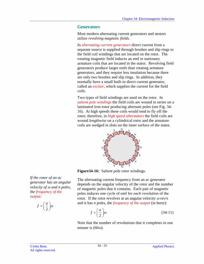
Two types of field windings are used on the rotor. In salient pole windings the field coils are wound in series on a laminated iron rotor producing alternate poles (see Fig. 34-16). At high speeds these coils would tend to fly off the rotor; therefore, in high speed alternators the field coils are wound lengthwise on a cylindrical rotor and the armature coils are wedged in slots on the inner surface of the stator.
Figure34-16: Salient pole rotor windings.
If the rotor of an ac generator has an angular velocity of ω and n poles, the frequency of the output:
2nf ω⎛ ⎞= ⎜ ⎟
⎝ ⎠
The alternating current frequency from an ac generator depends on the angular velocity of the rotor and the number of magnetic poles that it contains. Each pair of magnetic poles induces one cycle of emf for each revolution of the rotor. If the rotor revolves at an angular velocity ω rev/s and it has n poles, the frequency of the output (in hertz):
2nf ω⎛ ⎞= ⎜ ⎟
⎝ ⎠ (34-11)
Note that the number of revolutions that it completes in one minute is (60ω).
©John Betts Applied Physics All rights reserved.
34 - 25
Chapter 34: Electromagnetic Induction
Example 34-5 Determine the angular velocity of the rotor in a six-pole alternator that produces an alternating current output at a frequency of 60.0 Hz.
Solution n = 6, f = 60.0 Hz
From Equation 34-11:
2 2(60.0 Hz) rev200 = 1800 rpm6 s
fn
ω = = =
In polyphase alternators two or more magnetic fields are located symmetrically on the rotor to produce emfs with different phases simultaneously. For example, three phase alternators are commonly used to produce three outputs with phase angles that differ by 120°.
Direct current generators are essentially alternating current generators with either commutators that change the output connections, or solid-state devices called rectifiers that only pass direct current. Some direct current generators, called magnetos, have permanent magnets to produce the magnetic fields; however, in most generators and electric motors the magnetic fields are produced by electromagnets. Commutator contacts and brushes wear out much more quickly than slip rings; therefore, after reliable and inexpensive silicon diodes were developed the direct current generator essentially became obsolete.
Alternating Current Motors In all electric motors (ac and dc) alternating current is applied to the armature windings producing a rotating magnetic field. These armature windings may be located on the rotor or in the stator. The armature winding produce a magnetic field that interacts with the magnetic field developed by the field coils (or permanent magnet), causing the rotor to rotate.
Alternating current synchronous motor has either a permanent magnet or an electromagnet supplied by direct current on the rotor. A fixed-frequency alternating current is applied to the field coils on the stator, producing a magnetic field that rotates with a fixed angular velocity. The magnetic field of a permanent magnet or an electromagnet on the rotor
Applied Physics ©John Betts All rights reserved.
34 - 26
Chapter 34: Electromagnetic Induction
The synchronous speed of the synchronous motor:
2 2s
ffn n
ω ⎛ ⎞= =⎜ ⎟⎝ ⎠
Where f is the alternating current frequency and n is the number of field poles.
locks with this rotating magnetic field (poles aligned north against south) causing the rotor to rotate. The rotor rotation frequency is synchronized with the alternating current frequency f input to the field coils. Since each pair of poles produces one rotation of the magnetic field for each cycle, if there are n poles the angular velocity of the magnetic field (in rev/s) and the rotor (the synchronous speed):
S2 2 ffn n
ω ⎛ ⎞= =⎜ ⎟⎝ ⎠
(34-12)
Example 34-6 Determine the angular velocity (synchronous speed) of a synchronous motor with four poles if a 60.0 Hz alternating current is applied to its field coils.
Solution n = 4, f = 60.0 Hz
From Equation 34-12:
S2 2(60.0 Hz) rev30.0 1800 rpm
4 sf
nω = = = =
In an alternating current (asynchronous) induction motor normally one or three–phase alternating is applied to the field windings in the stator, producing a radial rotating magnetic field that is synchronous to the applied alternating current similar to that in synchronous motors. However, in these machines the rotors have conductors that provide paths for induced electric current. The rotors do not have permanent magnets or connections to any external current source. Induction motors are used in devices such as refrigerators, washing machines, and furnaces. In linear induction motors the poles are either mounted on the vehicle that runs over a linear track, or on a linear track. These types of motors are capable of producing very high speed, particularly with magnetic levitation.
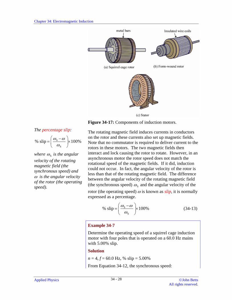
Squirrel cage motors have rotors consisting of laminated iron cylinders with embedded slots containing copper or aluminum bars interconnected by solid copper rings at each end (see Fig. 34-17a). Wound rotor motors have windings of insulated wire coils that are interconnected to produce the same number of poles as the stator (see Fig. 34-17b). In each case the rotor conductors provide low resistance paths for induced electric currents.
©John Betts Applied Physics All rights reserved.
34 - 27
Chapter 34: Electromagnetic Induction
Figure 34-17: Components of induction motors.
The percentage slip:
S
S
% slip 100%ω ωω
⎛ ⎞−= ×⎜ ⎟
⎝ ⎠
where Sω is the angular velocity of the rotating magnetic field (the synchronous speed) and ω is the angular velocity of the rotor (the operating speed).
The rotating magnetic field induces currents in conductors on the rotor and these currents also set up magnetic fields. Note that no commutator is required to deliver current to the rotors in these motors. The two magnetic fields then interact and lock causing the rotor to rotate. However, in an asynchronous motor the rotor speed does not match the rotational speed of the magnetic fields. If it did, induction could not occur. In fact, the angular velocity of the rotor is less than that of the rotating magnetic field. The difference between the angular velocity of the rotating magnetic field (the synchronous speed) Sω and the angular velocity of the rotor (the operating speed) ω is known as slip, it is normally expressed as a percentage.
S
S
% slip 100%ω ωω
⎛ ⎞−= ×⎜ ⎟
⎝ ⎠ (34-13)
Example 34-7 Determine the operating speed of a squirrel cage induction motor with four poles that is operated on a 60.0 Hz mains with 5.00% slip.
Solution n = 4, f = 60.0 Hz, % slip = 5.00%
From Equation 34-12, the synchronous speed:
Applied Physics ©John Betts All rights reserved.
34 - 28
Chapter 34: Electromagnetic Induction
3S
120 120(60.0 Hz) 1.80 x 10 rpm4
fn
ω = = =
The slip = 0.0500; therefore, from Equation 34-13, the operating speed:
S (1 slip) (1800 rpm)(1 0.0500) 1710 rpmω ω= − = − =
Slip is positive-valued for motors and negative-valued for generators. The slip in typical induction motors increases as the load increases; however, they normally operate with between 5 and 10 % slip. However, the torque increases as the slip increases. Synchronous motors do not have the same problem with slip and speed variations being dependent on the load; however, they require starter mechanisms to bring the motor up to speed.
The angular velocity and position of electronically controlled AC motors is accomplished by varying the frequency and phase of the potential difference to the armature, which controls the rotating magnetic field.
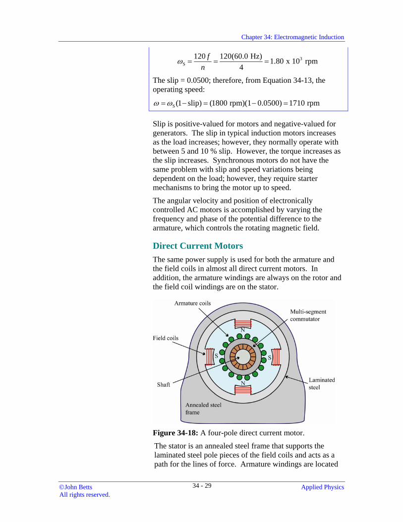
Direct Current Motors The same power supply is used for both the armature and the field coils in almost all direct current motors. In addition, the armature windings are always on the rotor and the field coil windings are on the stator.
Figure 34-18: A four-pole direct current motor.
The stator is an annealed steel frame that supports the laminated steel pole pieces of the field coils and acts as a path for the lines of force. Armature windings are located
©John Betts Applied Physics All rights reserved.
34 - 29
Chapter 34: Electromagnetic Induction
in slots in the cylindrical steel core of the rotor. Brushes make electrical contact with a multi-segment commutator (see Fig. 34-18). Direct current motors are used for traction and where constant speed is required. For example, they are very suitable for starting high inertia loads, such as trains, and in sheet metal rolling mills.
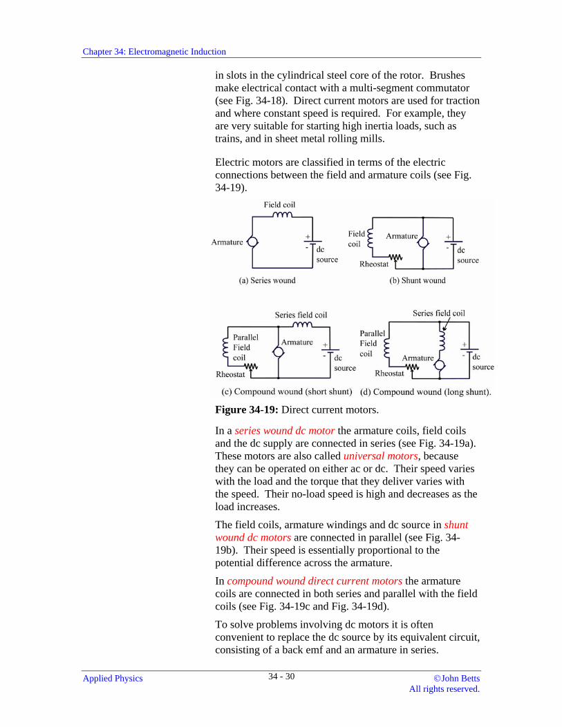
Electric motors are classified in terms of the electric connections between the field and armature coils (see Fig. 34-19).
Figure 34-19: Direct current motors.
In a series wound dc motor the armature coils, field coils and the dc supply are connected in series (see Fig. 34-19a). These motors are also called universal motors, because they can be operated on either ac or dc. Their speed varies with the load and the torque that they deliver varies with the speed. Their no-load speed is high and decreases as the load increases.
The field coils, armature windings and dc source in shunt wound dc motors are connected in parallel (see Fig. 34-19b). Their speed is essentially proportional to the potential difference across the armature.
In compound wound direct current motors the armature coils are connected in both series and parallel with the field coils (see Fig. 34-19c and Fig. 34-19d).
To solve problems involving dc motors it is often convenient to replace the dc source by its equivalent circuit, consisting of a back emf and an armature in series.
Applied Physics ©John Betts All rights reserved.
34 - 30
Chapter 34: Electromagnetic Induction
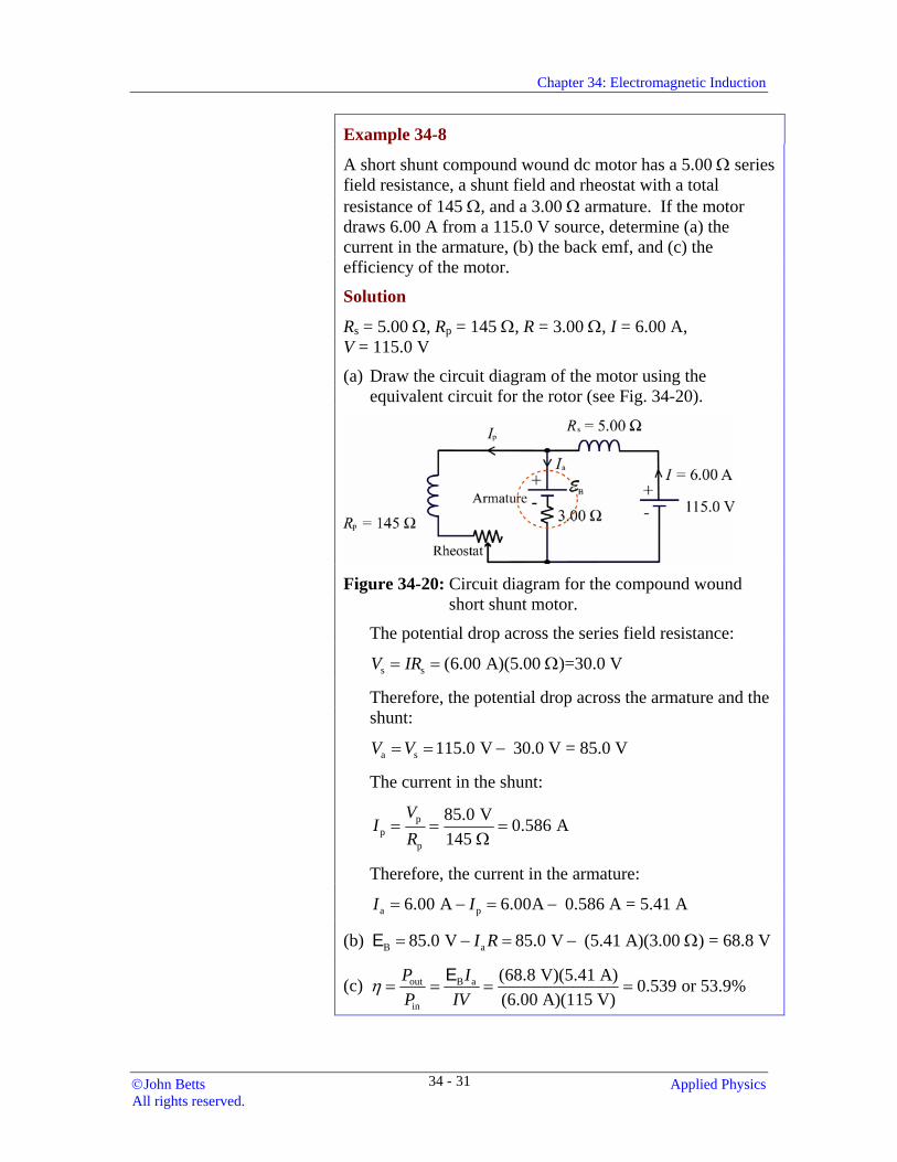
Example 34-8
A short shunt compound wound dc motor has a 5.00 Ω series field resistance, a shunt field and rheostat with a total resistance of 145 Ω, and a 3.00 Ω armature. If the motor draws 6.00 A from a 115.0 V source, determine (a) the current in the armature, (b) the back emf, and (c) the efficiency of the motor.
Solution
Rs = 5.00 Ω, Rp = 145 Ω, R = 3.00 Ω, I = 6.00 A, V = 115.0 V
(a) Draw the circuit diagram of the motor using the equivalent circuit for the rotor (see Fig. 34-20).
Figure 34-20: Circuit diagram for the compound wound
short shunt motor.
The potential drop across the series field resistance:
s s (6.00 A)(5.00 )=30.0 VV IR= = Ω
Therefore, the potential drop across the armature and the shunt:
a s 115.0 V 30.0 V = 85.0 VV V= = −
The current in the shunt:
pp
p
85.0 V 0.586 A145
VI
R= = =
Ω
Therefore, the current in the armature:
a p6.00 A 6.00A 0.586 A = 5.41 AI I= − = −
(b) B a85.0 V 85.0 V (5.41 A)(3.00 ) = 68.8 VI R= − = − ΩE
(c) out B a
in
(68.8 V)(5.41 A) 0.539 or 53.9%(6.00 A)(115 V)
P IP IV
η = = = =E
©John Betts Applied Physics All rights reserved.
34 - 31
Chapter 34: Electromagnetic Induction
Exercises 17. Determine the angular velocity of the rotor in an eight-
pole alternator that produces an alternating current output at a frequency of 60.0 Hz.
18. A four-pole alternator produces an alternating current output at a frequency of 50.0 Hz. What is the angular velocity of the rotor?
19. An alternator produces alternating current at a frequency of 120 Hz when the angular velocity of the rotor is 1800 rpm. Determine the number of magnetic poles in the alternator.
20. Determine the synchronous speed of a synchronous motor with six poles if a 50.0 Hz alternating current is applied to its field coils.
21. The synchronous speed of a motor is 3.60 x 10³ rpm when it is connected to a 60.0 Hz line. How many poles does the motor have?
22. Calculate the percentage slip of an induction motor that has a synchronous speed of 3.60 x 10³ rpm and an operating speed of 3250 rpm.
23. Determine the operating speed of a squirrel cage induction motor with six poles that is operated on a 60.0 Hz mains with 7.50% slip.
24. A six-pole induction motor is connected to a 60.0 Hz line and has an operating speed of 1100 rpm. What is the percentage slip?
25. A series wound dc motor has a 4.50 Ω series field coil and a 3.00 Ω armature. Determine the back emf when it draws 1.15 A from a 115 V source.
26. A shunt wound dc motor has a 7.25 Ω armature, and a field coil and a rheostat that have a combined resistance of 125 Ω. Determine the back emf if the motor draws 8.00 A from a 118.0 V source.
27. A long shunt compound wound dc motor has a 6.25 Ω armature in series with a 5.75 Ω series field coil, and a rheostat and shunt field coil with a total resistance of 215 Ω. Determine (a) the back emf, and (b) the efficiency of the motor when it draws 6.00 A from a 115 V source.
Applied Physics ©John Betts All rights reserved.
34 - 32
Chapter 34: Electromagnetic Induction
28. A long shunt compound wound dc motor has a 6.00 Ω series field resistance, an 80.0 Ω shunt field resistance and a 2.00 Ω armature. When the motor is connected to a 120.0 V source it draws 8.00 A. Find (a) the back emf, and (b) the efficiency of the motor.
29. A short-shunt compound dc motor has a series field resistance of 2.00 Ω and a 75.0 Ω shunt resistance. If the armature resistance is 3.00 Ω and the motor draws 6.00 A when connected to a 115 V supply, find (a) the back emf, and (b) the efficiency.
30. A dc shunt wound motor has a 4.00 Ω armature and a 46.0 Ω shunt field coil. If it is connected to a 115 V source, (a) what is the initial current in the motor? (b) What resistance must be connected in series with the motor and the supply in order to limit the starting current to 8.00 A? When the motor runs at the rated speed the series resistance R is removed and the motor draws 8.00 A from the 115 V supply. (c) Determine the back emf that is developed by the motor. (d) What is its efficiency?
Summary Time-varying magnetic fields produce electric currents and potential differences by a process known as electromagnetic induction.
An electric current and an electromotive force are induced in a conductor only when it experiences a time-varying magnetic field. Lenz's law states that the induced emf produces an induced electric current that it sets up a magnetic field to oppose the change in the magnetic flux.
Faraday's law states that the induced emf E in a circuit is equal to the negative time rate of change of magnetic flux Φ through the circuit:
E = −∆Φ∆t
If the circuit has N turns:
E = − FHGIKJ = −N
tNt
∆Φ∆
∆ Φ∆
( )
The flux linkage in the circuit = NΦ
©John Betts Applied Physics All rights reserved.
34 - 33
Chapter 34: Electromagnetic Induction
The emf induced in a length of a conductor that moves at a speed v and an angle θ with a magnetic field where the magnetic induction is B:
E = v B sinθ
The right hand rule: Align the fingers of the right hand in the direction of the velocity with the palm facing the direction of the magnetic induction and the straightened thumb gives the direction of the conventional electric current in the conductor.
A basic ac generator or alternator consists of a tightly wound armature is mounted between the poles of a magnet so that it is free to rotate about an axis perpendicular to the magnetic induction. The ends of the armature are connected to circular-shaped metallic slip rings that slide over stationary graphite brushes making electric contact.
The instantaneous emf induced in a flat coil of area A with N turns that rotates with an angular velocity ω in a uniform magnetic induction B:
or EE
==
NBA tNBA
ω ωω θ
sinsin
where θ ω= t is the phase angle.
One complete revolution of the coil produces one cycle of the induced alternating current.
An alternating current generator may be converted into a direct current generator by using a single split ring called a commutator instead of the two slip rings.
Fluctuations in the output emf and current are called ripple. It is reduced by using multiple coils wound with different orientations on the armature.
Most of our electricity is generated as alternating current. Common sources of electric energy are: fossil fuels, internal combustion engines, hydroelectric power, wind energy, and nuclear reactors.
Electric generators and motors have two main components: a rotating section called the rotor that is located in a stationary frame or yoke called a stator.
There is a magnetic torque opposing the rotation on the induced electric current in a generator. This is known as the motor effect; it is an example of Lenz’s law.
Applied Physics ©John Betts All rights reserved.
34 - 34
Chapter 34: Electromagnetic Induction
A torque is exerted on a current-carrying coil in a magnetic field, causing it to rotate. A back or counter emf is induced in this rotating coil in opposition to the applied emf.
If the rotor of an ac generator has an angular velocity of ω (in rev/s) and n poles, the frequency of the output:
2nf ω
=
The synchronous speed of a synchronous motor: 2
sf
nω =
where f is the alternating current frequency and n is the number of field poles.
The percentage slip:
S
S
% slip 100%ω ωω
⎛ ⎞−= ×⎜ ⎟
⎝ ⎠
where Sω is the angular velocity of the rotating magnetic field (the synchronous speed) and ω is the angular velocity of the rotor (the operating speed).
Questions 1. Why are the armature coils of the rotor usually wound on an iron core?
2. Describe the currents that are induced in a coil of wire: (a) when a south pole is thrust into the core, (b) when the pole is stationary in the core, and (c) when the south pole is removed from the core.
3. Describe the structures and functions of the following generator and motor components: (a) brushes, (b) slip rings, and (c) commutators.
4. Simple motors and generators have the same structures; explain the difference in their operations.
5. How would you increase the output voltage from a generator?
6. Describe the output voltages from the following: (a) an alternator, (b) a simple dc generator, and (c) a dc generator with a multi-segment commutator.
7. What is the main difference between revolving armature coil and revolving field generators?
©John Betts Applied Physics All rights reserved.
34 - 35
Chapter 34: Electromagnetic Induction
8. Describe the difference between a synchronous and an asynchronous motor.
9. Why must slip be present in order for an induction motor to operate?
10. Can the back emf ever exceed the applied potential difference? Explain your answer.
Review Exercises
1. Calculate the average emf that is induced in a 75 turn coil that experiences a steady change in magnetic flux from 9.28 mWb to 7.44 mWb in 5.80 ms.
2. Determine the change in magnetic flux in a 45-turn coil that would maintain an average emf of 25.0 V for 22.5 µs.
3. A 25-turn solenoid with a radius of 1.25 cm is located in a magnetic field with the normal to its surface parallel to the magnetic induction. Determine the average emf that is induced in the solenoid when the magnetic induction changes steadily from 625 mT to 125 mT in 225 µs.
4. A long solenoid in air has 75 turns/cm; a radius of 1.25 cm and it carries a steady current of 575 mA. A second solenoid with 1200 turns of diameter of 8.75 mm is located in its centre with its axis parallel to the first solenoid. Determine the emf induced in the second solenoid when the current in the first solenoid changes at a rate of −18.6 A/s.
5. A solenoid of radius 7.50 mm and length 15.0 cm has 120 turns and is located in a magnetic field with its axis parallel to the flux density. Determine the time rate of change of the flux density that would induce a 7.80 V emf in the coil.
6. A 2.75 cm long wire conductor with a resistance of 22.0 mΩ moves at 7.25 m/s at an angle of 32.0° through a uniform magnetic induction of 825 mT. (a) Determine the induced emf in the conductor. (b) Calculate the current in the circuit when the ends of the conductor are connected across a 775 mΩ resistance.
7. A 15-turn coil is 5.00 cm long, 2.00 cm wide and rotates at 275 rpm about a perpendicular axis in a uniform 750 mT magnetic induction. Determine (a) the maximum induced emf in the coil, and (b) the emf induced in the coil 25.0 ms after it passes the vertical position where the emf is zero.
Applied Physics ©John Betts All rights reserved.
34 - 36
Chapter 34: Electromagnetic Induction
8. Determine the angular velocity of the rotor in a four-pole alternator that produces an alternating current output at a frequency of 50.0 Hz.
9. Determine the synchronous speed of a synchronous motor with two poles if a 60.0 Hz alternating current is applied to its field coils.
10. Calculate the percentage slip of an induction motor that has a synchronous speed of 1.80 x 10³ rpm and an operating speed of 1690 rpm.
11. Determine the operating speed of a squirrel cage induction motor with six poles that is operated on a 60.0 Hz mains with 8.25% slip.
12. A series wound dc motor has a 6.80 Ω series field coil and a 2.20 Ω armature. Determine the back emf when it draws 7.50 A from a 115 V source.
13. A shunt wound dc motor has a 6.00 Ω armature, and a field coil and a rheostat that have a combined resistance of 152 Ω. Determine the back emf if the motor draws 11.0 A from a 110.0 V source.
14. A short-shunt compound wound dc motor has a 1.50 Ω armature in series with an 1.75 Ω series field coil, and a rheostat and shunt field coil with a total resistance of 175 Ω. Determine (a) the back emf, and (b) the efficiency of the motor when it draws 13.0 A from a 115.0 V source.
15. A dc shunt wound motor has a 4.00 Ω armature and a 46.0 Ω shunt field coil. If it is connected to a 115 V source, (a) what is the initial current in the motor? (b) What resistance R must be connected in series with the motor and the supply in order to limit the starting current to 8.00 A? When the motor runs at the rated speed the series resistance R is removed and the motor draws 8.00 A from the 115 V supply. (c) Determine the back emf that is developed by the motor. (d) What is its efficiency?
©John Betts Applied Physics All rights reserved.
34 - 37
Chapter 34: Electromagnetic Induction
Practice Test Total time allotted 30 min. Complete all solutions on a separate sheet of paper without referring to your notes or this manual.
Constants: g = 9.81 m/s2
Equations:
E = − FHGIKJN
t∆Φ∆
E = v B sinθ
E ==
NBA tNBA
ω ωω θ
sinsin
2nf ω
=
2s
fn
ω =
S
S
% slip 100%ω ωω
⎛ ⎞−= ×⎜ ⎟
⎝ ⎠
V IR=
1. A compound pendulum is made of an aluminum bar that oscillates about a pivot. If the bar swings through a gap between the poles of a permanent magnet the oscillation rapidly ceases. Explain why.
2. A 120-turn solenoid with a radius of 1.10 cm is located in a magnetic field with the normal to its surface parallel to the magnetic induction. Determine the average emf that is induced in the solenoid when the magnetic induction changes steadily from 875 mT to 45 mT in 315 µs.
3. A 1.25 cm long wire conductor with a resistance of 18.0 mΩ moves at 4.75 m/s at an angle of 72.0° through a uniform magnetic induction of 775 mT. (a) Determine the induced emf in the conductor. (b) Calculate the current in the circuit when the ends of the conductor are connected across a 722 mΩ resistance.
4. Calculate the operating speed of a squirrel cage induction motor with four poles that is operated on a 60.0 Hz mains with 7.75% slip.
5. A dc series wound motor has a 2.20 Ω armature and a 3.80 Ω field coil. If it is connected to a 115 V source, (a) what is the initial current in the motor? (b) What resistance R must be connected in series with the motor and the supply in order to limit the starting current to 7.50 A? When the motor runs at the rated speed the series resistance R is removed and the motor draws 9.00 A from the 115 V supply. (c) Determine the back emf that is developed by the motor. (d) What is the efficiency of the motor at this speed?
Check your answers with those provided on page 34-38. Redo any questions that you did not solve correctly. If you still do not obtain the correct answers check with your instructor.
Applied Physics ©John Betts All rights reserved.
34 - 38
Chapter 34: Electromagnetic Induction
Answers to Exercises
1. 8.75 V 2. 44.3 V 3. 15 4. 41.3 mV 5. −1.02 T/s 6. 22.9 mV 7. 3.68 mT/s 8. 23.0 mV 9. 2.95 V 10. (a) 15.9 mV, (b) 13.3 mA 11. (a) 159 mV, (b) 79.3 mV 12. (a) 0.380 V, (b) 3.16 V/m, 0.266 A
13. The current in the wire: B viR R
= =E
Therefore, the mechanical power: 2 2 2
( ) B v BP Fv i B v Bv vR R
⎛ ⎞= = = =⎜ ⎟⎝ ⎠
The thermal power: 22 2( ) 2 2B v B vP
R R R= = =
E
The two expressions are equal. 14. (a) 4.89 V, (b) 4.23 V 15. 1780 rpm 16. 213 mT 17. 9.00 x 10² rpm 18. 1.50 x 10³ rpm 19. 4 20. 1.00 x 10³ rpm 21. 2 22. 9.72% 23. 1.20 x 10³ rpm 24. 8.3% 25. 106V 26. 63.3 V 27. 49.4 V 28. (a) 68.0 V, (b) 46.0% 29. (a) 89.1 V, (b) 59.8% 30 (a) 31.3 A, (b) 10.7 Ω, (c) 93.0 V, (d) 55.6%
Answers to Questions
1. The ferromagnetic core increases the magnetic induction.
2. (a) A current is induced in the core. The magnetic field of this current opposes the motion of the south magnetic pole into the core; therefore, its magnetic field has a south pole facing the south pole of the magnet.
©John Betts Applied Physics All rights reserved.
34 - 39
Chapter 34: Electromagnetic Induction
(b) No current is induced in the core when there is no change in the magnetic flux. (c) Again, the magnetic field of this current opposes the motion of the south magnetic pole away from the core; therefore, its magnetic field has a north pole facing the south pole of the magnet.
3. (a) Graphite brushes make contacts with commutators or slip rings to transfer electricity to or from the armatures. (b) Slip rings are circular conductors attached to the ends of the armature. They make electric contact with the brushes. (c) A commutator is a single split ring that makes electric contact with the brushes. It is constructed so that the brushes change contact to the other half of the ring as the armature rotates past the position where the normal to its area is parallel to the magnetic induction.
4. In a generator, mechanical energy is used to produce the rotations required to generate electricity. In a motor electricity produces the mechanical rotations.
5. The emf generated: E = NBA tω ωsin ; therefore, the output voltage can be increased by increasing the magnetic induction or the angular velocity. If the armature can be changed the output could also be increased by increasing the number of turns and the area of the armature coil.
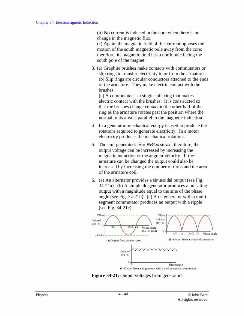
6. (a) An alternator provides a sinusoidal output (see Fig. 34-21a). (b) A simple dc generator produces a pulsating output with a magnitude equal to the sine of the phase angle (see Fig. 34-21b). (c) A dc generator with a multi-segment commutator produces an output with a ripple (see Fig. 34-21c).
Figure 34-21: Output voltages from generators.
Physics ©John Betts All rights reserved.
34 - 40
Chapter 34: Electromagnetic Induction
7. Rotating armature: The emf is induced in the armature as it rotates in the magnetic field of the field coils that are located in the stator. Rotating field generator: Direct current from a separate source is supplied through brushes and slip rings to the field coil windings on the rotor. The rotating magnetic field induces an emf in stationary armature coils that are located in the stator.
8. In a synchronous motor a fixed-frequency alternating current is applied to the field coils on the stator, producing a magnetic field that rotates with a fixed angular velocity. The magnetic field of a permanent magnet or an electromagnet on the rotor locks with this rotating magnetic field (poles aligned north against south) causing the rotor to rotate. The rotor rotation frequency is synchronized with the alternating current frequency f input to the field coils.
In an asynchronous motor the rotors do not have permanent magnets or connections to any external current source. The rotating magnetic field induces currents in conductors on the rotor and these currents also set up magnetic fields. No commutator is required to deliver current to the rotors. The two magnetic fields then interact and lock causing the rotor to rotate. However, in an asynchronous motor the rotor speed does not match the rotational speed of the magnetic fields.
9. If there is no slip there would be no change in the magnetic field and no induction would occur.
10. No. That is essentially perpetual motion.
Answers to Review Exercises
1. 23.8 V 2. 12.5 µWb 3. 27.3 V 4. 0.103 V 5. 368 T/s 6. (a) 87.2 mV, (b) 0.109 A 7. (a) 0.324 V, (b) 0.214 V 8. 1.50 x 10³ rpm 9. 3.60 x 10³ rpm 10. 6.11% 11. 1.10 x 10³ rpm 12. 47.5 V 13. 48.3 V 14. (a) 31.3 A, (b) 10.7 Ω, (c) 54.0 V, (d) 55.6%
©John Betts Applied Physics All rights reserved.
34 - 41
Chapter 34: Electromagnetic Induction
Practice Test Answers
1. Eddy currents are set up in the aluminum. The magnetic
fields of these eddy currents oppose the motion of the pendulum.
2. 1.20 x 10² V
3. (a) 43.8 mV, (b) 59.1 mA
4. 1660 rpm
5. (a) 19.2 A, (b) 9.3 Ω, (c) 61.0 V, (d) 53.0%
Physics ©John Betts All rights reserved.
34 - 42
Chapter 34: Electromagnetic Induction
Index Ac generator (alternator), 15, 34 Alternating current, 21, 34 Alternating current induction motor, 27 Alternating current energy sources, 21 Alternating current generators, 25 Alternating current motors, 26 Alternator, 15, 34 Armature, 15, 34 Back emf in motors, 23 Back or counter emf, 23, 35 Brushes, 15, 34 Commutator, 19, 34 Compound wound direct current motor, 30 Conventional electric current, 10, 34 Cycle, 17, 34 Direct current generator, 18, 26, 34 Direct Current Motors, 29 Eddy currents, 12 Electric generators, 15 Electric motor, 26 Electromagnetic induction, 2, 33 Emf induced, 10, 34 Excitor, 25 Faraday’s law of induction, 4, 7, 33 Flux linkage, 7, 33 Fossil fuels, 21 Frequency output ac generator (alternator), 25, 35 Generator, 23, 25 Geothermal energy, 21 High speed alternators, 25 Hydroelectric power, 21 Induced current, 4 Induced electromotive force (emf) , 4, 10, 34 Instantaneous emf
generator, 16 induced in flat coil, 34
Internal combustion engines, 21
Left-hand rule, 9 Lenz’s law, 5, 23, 33, 34 Linear induction motor, 27 Magnetic fields due to electric currents, 6 Magneto, 26 Motion of a conductor in a magnetic field, 8 Motor, 23 Motor effect, 23, 34 Nuclear reactors, 22 Oceanic tides,, 21 Penstock, 21 Percentage slip, 28, 35 Phase angle, 16, 34 Polyphase alternators, 26 Potential difference, 10 Relative motion magnetic pole and a conductor, 4 Right hand rule, 10, 34 Ripple, 20, 34 Rotor, 23, 34 Salient pole windings, 25 Scroll case, 21 Series wound dc motor, 30 Shunt wound dc motors, 30 Slip, 28 Slip rings, 15, 34 Solar energy, 21 Sources of electric energy, 22, 34 Squirrel cage motor, 27 Stator, 23 Synchronous motor, 27 Synchronous speed, 27, 35 Time-varying magnetic field, 4, 33 Universal motors, 30 Wind energy, 22 Wind farms, 22 Wound rotor motor, 27
©John Betts Applied Physics All rights reserved.
34 - 43