Embed Size (px)
Citation preview
Chapter 3
BIOMASS ENERGY – GASIFICATION TECHNOLOGY
_____________________________________________________________
3.1 Potential of Biomass
Biomass can be defined as solar energy stored in the form of organic
matter like plants or animal residues that have a net positive value as a
chemical resource.
India, being agriculture based country is having high potential for
biomass. The common biomass abundantly available in rural India is
agricultural residues like rice husk, groundnut shell, coconut shell, bagasse,
corn cobs, rice straw, cotton stalks, animal dung, forest wastes like bark,
chips, saw dust, fire wood etc. India produces a huge quantity of agricultural
residues, which can be converted into energy. The age-old practice of direct
burning of agricultural residues to generate energy for domestic as well as
industrial applications is very inefficient. Amongst the different technologies
available for energy conversion of biomass like biomass briquitting, biomass
combustion, bio-methanation, biomass gasification, biomass cogeneration,
biomass digestion etc., Biomass gasification is one of the efficient and useful
technologies.
Biomass gasification means incomplete combustion of biomass resulting
in production of combustible gases consisting of Carbon monoxide (CO),
Hydrogen (H2) and traces of Methane (CH4). This mixture is called producer
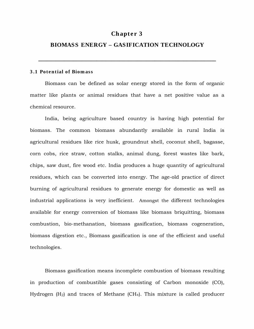
gas. Producer gas can be used to run internal combustion engines (both
compression and spark ignition), it can be used as substitute for furnace oil in
direct heat applications and can be used to produce, in an economically viable
way, methanol – an extremely attractive chemical which is useful both as fuel
for heat engines as well as chemical feedstock for industries. Since any
biomass material can undergo gasification, this process is much more
attractive than ethanol production or biogas where only selected biomass
materials can produce the fuel.
Fig: 3.1 Use of Biomass for energy
Besides, there is a problem that solid wastes (available on the farm) are
seldom in a form that can be readily utilized economically. For example wood
wastes can be used in hog fuel boiler but the equipment is expensive and
energy recovery is low. As a result it is often advantageous to convert this
waste into more readily usable fuel form like producer gas hence, the
attractiveness of gasification.
However under present conditions, economic factors seem to provide the
strongest argument of considering gasification. In many situations where the
price of petroleum fuels is high or where supplies are unreliable the biomass
gasification can provide an economically viable system – provided the suitable
biomass feedstock is easily available.
3.2 Historical Background
The process of gasification to produce combustible from organic feeds was
used in blast furnaces over 180 years ago. The possibility of using this gas for
heating and power generation was soon realized and there emerged in Europe
producer gas systems, which used charcoal and peat as feed material. At the
turn of the century, petroleum gained wider use as a fuel, but during both
world wars and particularly World War II, shortage in petroleum supplies led to
widespread re-introduction of gasification. By 1945 the gas was being used to
power trucks, buses and agricultural and industrial machines. It is estimated
that there were close to 9000,000 vehicles running on producer gas all over the
world.
After World War II the lack of strategic impetus and the availability of cheap
fossil fuels led to general decline in the producer gas industry. However Sweden
continued to work on producer gas technology and the work was accelerated
after 1956 Suez Canal crisis. A decision was then made to include gasifiers in
Swedish strategic emergency plans. Research into suitable designs of wood
gasifiers, essentially for transport use, was carried out at the National Swedish
Institute for Agricultural Machinery Testing and is still in progress.
The contemporary interest in small scale gasifier R&D, for most part dates
from 1973 oil crisis. The manufacturing also took off with increased interest
shown in gasification technology. At present there are about 64 gasification
equipment manufacturers all over the world.
3.3 Producer gas fuel
Producer gas derived from biomass, typically contains 18-20% each of H2
and CO, 2% CH4 and rest inert gases like CO2 and N2. The lower calorific value
varies between 4.5 – 4.9 MJ/kg, with stochiometric air-to-fuel ratio being 1.25
+ 0.05 on mass basis. Some of the fundamental data relating to producer gas
are compared with pure gases in Appendix VI. The comparison of producer gas
with methane is more vital with regard to the internal combustion engine
operation. This is because most of the engines operating on gaseous fuels are
either close to pure methane (natural gas) or diluted methane (bio-gas, land-fill
gas). The fuel-air equivalence ratio (actual fuel to air ratio)/(stoichiometric fuel
to air ratio) at the flammability limits compares closely for both the gases, but
the laminar burning velocity for producer gas at the lean limits is much higher.
The laminar burning velocity for producer gas (at 0.1MPa, 300K) is about 0.5
m/sec, which is about 30% higher than methane. This feature is argued to
demand lower advancement in the ignition timing and needs consideration
while arriving at the optimum ignition timing for the producer gas fuel.
Like any other gaseous fuel, producer gas can be used for internal
combustion engine operation provided the gas is sufficiently clean such that
contaminant does not accumulate in the intermediary passages to the engine
cylinder. But this fuel has largely been left unexploited due to additional
perceptions, namely
auto-ignition tendency at higher compression ratio,
Large de-rating in power due to energy density being low.
However, these perceptions need re-examination and clarification. The
arguments against the classical view in favor of better knock resistivity are as
follows. Firstly, with the laminar burning velocity being high due to the
presence of hydrogen might reduce the tendency for the knock. Secondly, the
presence of inert in the raw gas (CO2 and N2) might suppress the pre-flame
reactions that are responsible for knocking on account of increased dilution.
Also the maximum flame temperature attainable with the producer gas being
lower compared to conventional fuels like methane, one could expect better
knock resistivity.
Further, there is a general perception that producer gas being a low-
density energy fuel, the extent of de-rating in power would be large when
compared to high energy density fuels like Natural Gas and Liquefied
Petroleum Gas. This could be misleading because what needs to be accounted
for comparison is the mixture energy density and not the fuel energy density.
On comparison with CH4, the mixture energy density for producer gas is lower
by 23% as reflected in Appendix VI. The product to reactant mole ratio for
producer gas is less than one. These two parameters could contribute to de-
rating of engine output. However, it might be possible to reduce de-rating by
working with engines of higher compression ratio, perhaps higher than what
has been examined using natural gas (CR=15.8).
3.4 Theory Of Gasification
The production of generator gas (producer gas) called gasification, is partial
combustion of solid fuel (biomass) and takes place at temperatures of about
10000C. The reactor is called a gasifier. The combustion products from
complete combustion of biomass generally contain nitrogen, water vapor,
carbon dioxide and surplus of oxygen. However in gasification where there is a
surplus of solid fuel (incomplete combustion) the products of combustion are
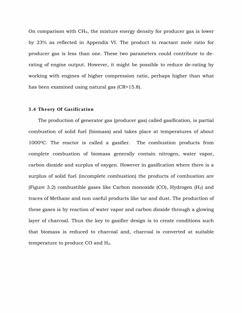
(Figure 3.2) combustible gases like Carbon monoxide (CO), Hydrogen (H2) and
traces of Methane and non useful products like tar and dust. The production of
these gases is by reaction of water vapor and carbon dioxide through a glowing
layer of charcoal. Thus the key to gasifier design is to create conditions such
that biomass is reduced to charcoal and, charcoal is converted at suitable
temperature to produce CO and H2.
Co
H2
CH4
Tar
Dust
Gasifier
Fig: 3.2 Products of Gasifier
3.5 Types of Gasifiers
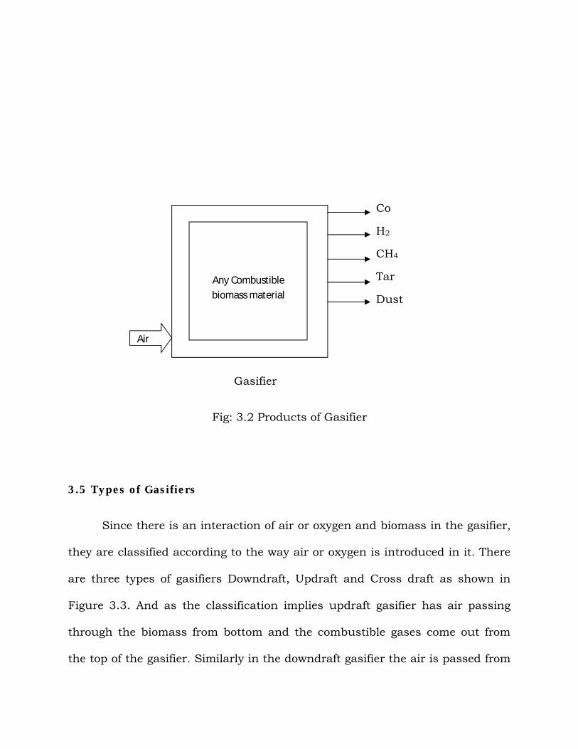
Since there is an interaction of air or oxygen and biomass in the gasifier,
they are classified according to the way air or oxygen is introduced in it. There
are three types of gasifiers Downdraft, Updraft and Cross draft as shown in
Figure 3.3. And as the classification implies updraft gasifier has air passing
through the biomass from bottom and the combustible gases come out from
the top of the gasifier. Similarly in the downdraft gasifier the air is passed from
Any Combustible biomass material
Air
the tuyers in the downdraft direction. With slight variation almost all the
gasifiers fall in the above categories.
Fig. 3.3. Various types of gasifiers
The choice of one type of gasifier over other is dictated by the fuel, its
final available form, its size, moisture content and ash content. Table 3.1 lists
therefore, the advantages and disadvantages generally found for various
classes of gasifiers.
Table 3.1 Advantages and Disadvantages of various Gasifiers
Sr. No. Gasifier
Type
Advantage Disadvantages
1. Updraft - Small pressure drop
- good thermal efficiency
- little tendency towards slag
- Great sensitivity to
tar and moisture
and moisture
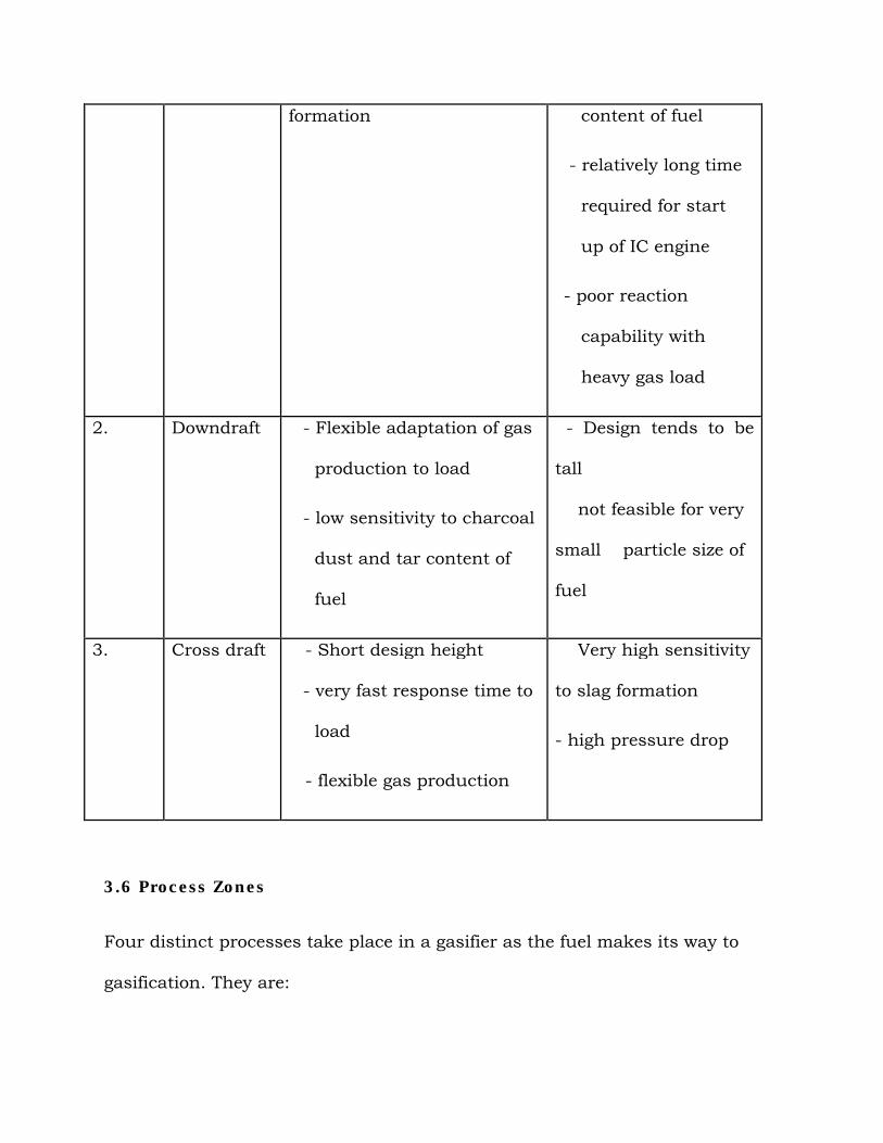
formation content of fuel
- relatively long time
required for start
up of IC engine
- poor reaction
capability with
heavy gas load
2. Downdraft - Flexible adaptation of gas
production to load
- low sensitivity to charcoal
dust and tar content of
fuel
- Design tends to be
tall
not feasible for very
small particle size of
fuel
3. Cross draft - Short design height
- very fast response time to
load
- flexible gas production
Very high sensitivity
to slag formation
- high pressure drop
3.6 Process Zones
Four distinct processes take place in a gasifier as the fuel makes its way to
gasification. They are:
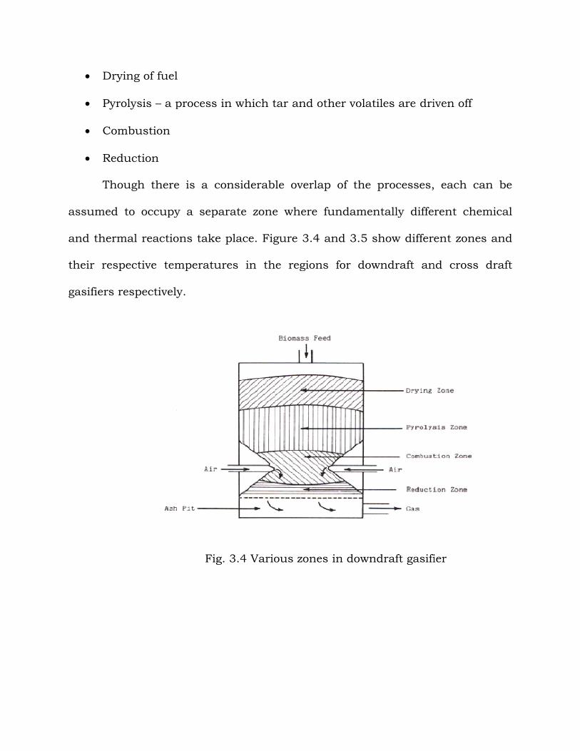
Drying of fuel
Pyrolysis – a process in which tar and other volatiles are driven off
Combustion
Reduction
Though there is a considerable overlap of the processes, each can be
assumed to occupy a separate zone where fundamentally different chemical
and thermal reactions take place. Figure
their respective temperatures in the
gasifiers respectively.
Fig. 3.4 Various zones in downdraft gasifier
a process in which tar and other volatiles are driven off
Though there is a considerable overlap of the processes, each can be
assumed to occupy a separate zone where fundamentally different chemical
and thermal reactions take place. Figure 3.4 and 3.5 show different zones and
their respective temperatures in the regions for downdraft and cross
Fig. 3.4 Various zones in downdraft gasifier
a process in which tar and other volatiles are driven off
Though there is a considerable overlap of the processes, each can be
assumed to occupy a separate zone where fundamentally different chemical
different zones and
regions for downdraft and cross draft
Fig. 3.4 Various zones in downdraft gasifier
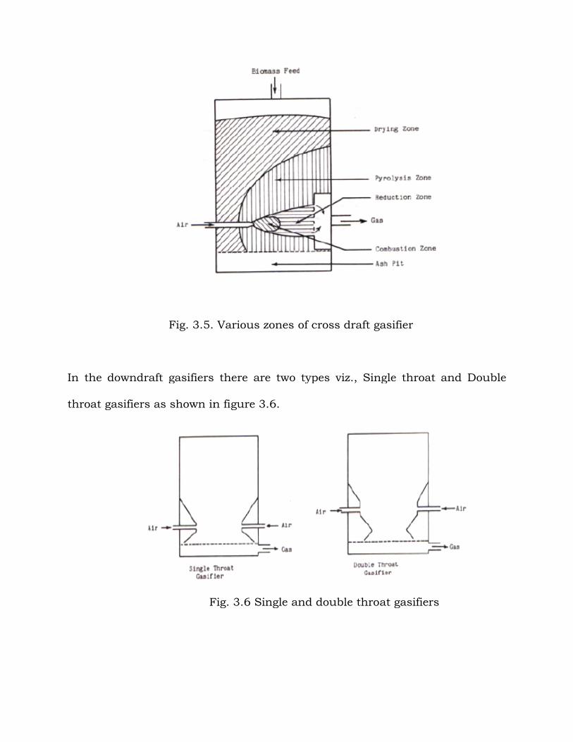
Fig. 3.5. Various zones of cross draft gasifier
In the downdraft gasifiers there are two types
throat gasifiers as shown in figure 3.6.
Fig. 3.6
Fig. 3.5. Various zones of cross draft gasifier
In the downdraft gasifiers there are two types viz., Single throat and Double
gasifiers as shown in figure 3.6.
Fig. 3.6 Single and double throat gasifiers
Single throat and Double
Single and double throat gasifiers
Single throat gasifiers are mainly used for stationary applications whereas
double throat are for varying loads as well as automotive purposes.
3.7 Reaction Chemistry
The following major reactions take place in combustion and reduction zone.
3.7.1 Combustion zone
The combustible substance of a solid fuel is usually composed of
elements carbon, hydrogen and oxygen. In complete combustion carbon dioxide
is obtained from carbon in fuel and water is obtained from the hydrogen,
usually as steam. The combustion reaction is exothermic and yields a
theoretical oxidation temperature of 14500C. The main reactions are:
C + O2 = CO2 (+ 393 MJ/kg mole) (1)
2H2 + O2 = 2H2 O (- 242 MJ/kg mole) (2)
3.7.2 Reaction zone
The products of partial combustion (water, carbon dioxide and
uncombusted partially cracked pyrolysis products) now pass through a red-hot
charcoal bed where the following reduction reactions take place.
C + CO2 = 2CO (- 164.9 MJ/kg mole) (3)
C + H2O = CO + H2 (- 122.6 MJ/kg mole) (4)
CO + H2O = CO + H2 (+ 42 MJ/kg mole) (5)
C + 2H2 = CH4 (+ 75 MJ/kg mole) (6)
CO2 + H2 = CO + H2O (- 42.3 MJ/kg mole) (7)
Reactions (3) and (4) are main reduction reactions and being endothermic
have the capability of reducing gas temperature. Consequently the
temperatures in the reduction zone are normally 800-10000C. Lower the
reduction zone temperature (~ 700-8000C), lower is the calorific value of gas.
3.7.3 Pyrolysis zone
Wood pyrolysis is an intricate process that is still not completely
understood. The products depend upon temperature, pressure, residence time
and heat losses. However following general remarks can be made about them.
Up to the temperature of 2000C only water is driven off. Between 200 to
2800C carbon dioxide, acetic acid and water are given off. The real pyrolysis,
which takes place between 280 to 5000C, produces large quantities of tar and
gases containing carbon dioxide. Besides light tars, some methyl alcohol is also
formed. Between 500 to 7000C the gas production is small and contains
hydrogen. Thus it is easy to see that updraft gasifier will produce much more
tar than downdraft one. In downdraft gasifier the tars have to go through
combustion and reduction zone and are partially broken down. Since majority
of fuels like wood and biomass residue do have large quantities of tar,
downdraft gasifier is preferred over others. Indeed majority of gasifiers, both in
World War II and presently are of downdraft type.
Finally in the drying zone the main process is of drying of wood. Wood
entering the gasifier has moisture content of 10-30%. Various experiments on
different gasifiers in different conditions have shown that on an average the
condensate formed is 6-10% of the weight of gasified wood. Some organic acids
also come out during the drying process. These acids give rise to corrosion of
gasifiers.
3.8 Properties of Producer gas
The producer gas is affected by various processes as outlined above hence
one can expect variations in the gas produced from various biomass sources.
The gas composition is also a function of gasifier design and thus, the same
fuel may give different calorific value as when used in two different gasifiers.
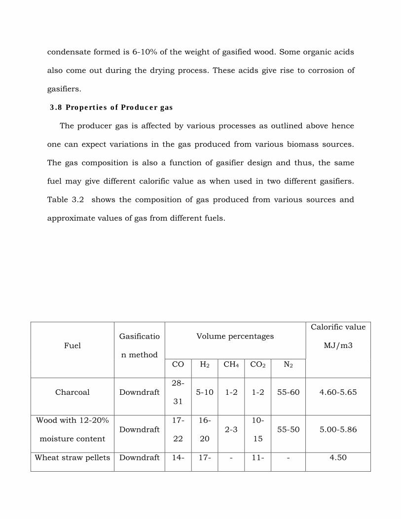
Table 3.2 shows the composition of gas produced from various sources and
approximate values of gas from different fuels.
FuelGasificatio
n method
Volume percentagesCalorific value
MJ/m3
CO H2 CH4 CO2 N2
Charcoal Downdraft28-
315-10 1-2 1-2 55-60 4.60-5.65
Wood with 12-20%
moisture contentDowndraft
17-
22
16-
202-3
10-
1555-50 5.00-5.86
Wheat straw pellets Downdraft 14- 17- - 11- - 4.50
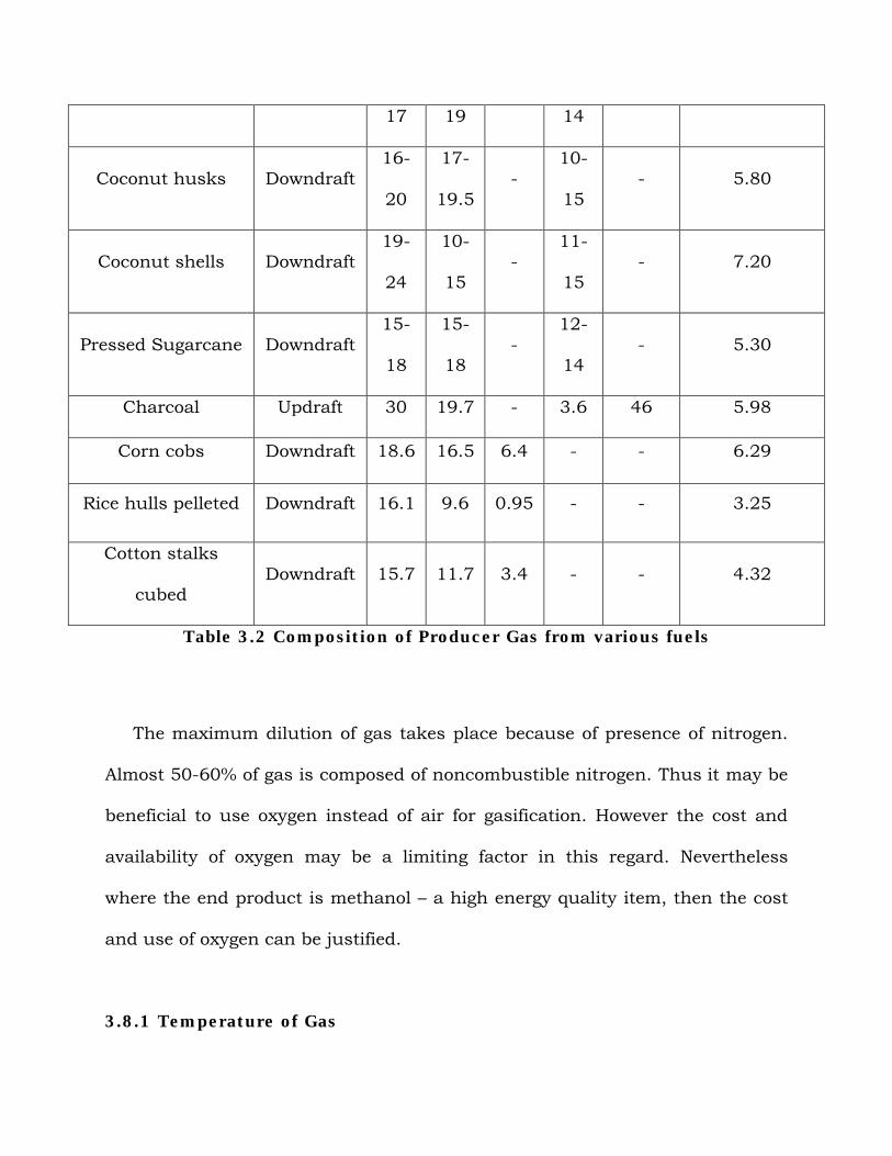
Table 3.2 Composition of Producer Gas from various fuels
The maximum dilution of gas takes place because of presence of nitrogen.
Almost 50-60% of gas is composed of noncombustible nitrogen. Thus it may be
beneficial to use oxygen instead of air for gasification. However the cost and
availability of oxygen may be a limiting factor in this regard. Nevertheless
where the end product is methanol – a high energy quality item, then the cost
and use of oxygen can be justified.
3.8.1 Temperature of Gas
17 19 14
Coconut husks Downdraft16-
20
17-
19.5-
10-
15- 5.80
Coconut shells Downdraft19-
24
10-
15-
11-
15- 7.20
Pressed Sugarcane Downdraft15-
18
15-
18-
12-
14- 5.30
Charcoal Updraft 30 19.7 - 3.6 46 5.98
Corn cobs Downdraft 18.6 16.5 6.4 - - 6.29
Rice hulls pelleted Downdraft 16.1 9.6 0.95 - - 3.25
Cotton stalks
cubedDowndraft 15.7 11.7 3.4 - - 4.32
On an average the temperature of gas leaving the gasifier is about 300 to
4000C. If the temperature is higher than 5000C, it is an indication that partial
combustion of gas is taking place. This generally happens when the air flow
rate through the gasifier is higher than the design value.
3.9 Gasifier Fuel Characteristics
Almost any carbonaceous or biomass fuel can be gasified under
experimental or laboratory conditions. However the real test for a good gasifier
is not whether a combustible gas can be generated by burning a biomass fuel
with 20-40% stoichiometric air but that a reliable gas producer can be made
which can also be economically attractive to the customer. Towards this goal
the fuel characteristics have to be evaluated and fuel processing to be done.
Many of gasifier manufacturers claim that a gasifier is available which can
gasify any fuel but there is no such thing as a universal gasifier. A gasifier is
very fuel specific and it is tailored around a fuel rather than the other way
round.
Thus a gasifier fuel can be classified as good or bad according to the
following parameters:
Energy content of the fuel
Bulk density
Moisture content
Dust content
Tar content
Ash and slagging characteristic
3.9.1 Energy content and Bulk Density of fuel
The higher the energy content and bulk density of fuel, the similar is the
gasifier volume since for one charge one can get power for longer time.
3.9.2 Moisture content
In most fuels there is very little choice in moisture content since it is
determined by the type of fuel, its origin and treatment. It is desirable to use
fuel with low moisture content because heat loss due to its evaporation before
gasification is considerable and the heat budget of the gasification reaction is
impaired. For example, for fuel at 250C and raw gas exit temperature from
gasifier at 3000C, 2875 KJ/kg heat must be supplied by fuel to heat and
evaporate moisture.
Besides impairing the gasifier heat budget, high moisture content also
puts load on cooling and filtering equipment by increasing the pressure drop
across these units because of condensing liquid. Thus in order to reduce the
moisture content of fuel some pretreatment of fuel is required. Generally
desirable moisture content for fuel should be less than 20%.
3.9.3 Dust content
All gasifier fuels produce dust. This dust is a nuisance since it can clog
the internal combustion engine and hence has to be removed. The gasifier
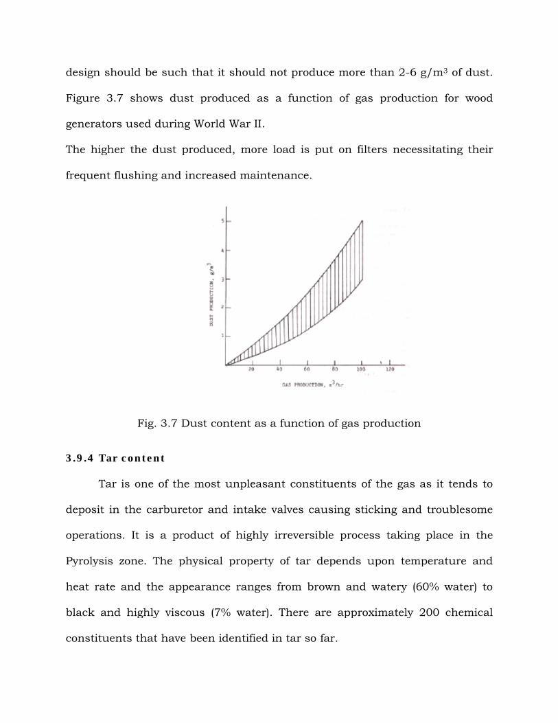
design should be such that it should not produce more t
Figure 3.7 shows dust produced as a function of gas production for wo
generators used during World War II.
The higher the dust produced, more load is put on filters necessitating their
frequent flushing and increased maintenance.
Fig. 3.7 Dust content as a function of gas production
3.9.4 Tar content
Tar is one of the most unpleasant constituents of the gas as it tends to
deposit in the carburetor and intake valves causing sticking and troublesome
operations. It is a product of highly ir
Pyrolysis zone. The physical property of tar depends upon temperature and
heat rate and the appearance ranges from brown and watery (60% water) to
black and highly viscous (7% water). There are approximately 200 chemi
constituents that have been identified in tar so far.
design should be such that it should not produce more than 2-6 g/m
7 shows dust produced as a function of gas production for wo
generators used during World War II.
The higher the dust produced, more load is put on filters necessitating their
frequent flushing and increased maintenance.
Dust content as a function of gas production
Tar is one of the most unpleasant constituents of the gas as it tends to
deposit in the carburetor and intake valves causing sticking and troublesome
operations. It is a product of highly irreversible process taking place in the
Pyrolysis zone. The physical property of tar depends upon temperature and
heat rate and the appearance ranges from brown and watery (60% water) to
black and highly viscous (7% water). There are approximately 200 chemi
constituents that have been identified in tar so far.
6 g/m3 of dust.
7 shows dust produced as a function of gas production for wood
The higher the dust produced, more load is put on filters necessitating their
Dust content as a function of gas production
Tar is one of the most unpleasant constituents of the gas as it tends to
deposit in the carburetor and intake valves causing sticking and troublesome
reversible process taking place in the
Pyrolysis zone. The physical property of tar depends upon temperature and
heat rate and the appearance ranges from brown and watery (60% water) to
black and highly viscous (7% water). There are approximately 200 chemical

Very little research work has been done in the area of removing or
burning tar in the gasifier so that relatively tar free gas comes out. Thus the
major effort has been devoted to cleaning this tar by filters and coolers. A well-
designed gasifier should put out less than 1 g/m3 of tar. Usually it is assumed
that a downdraft gasifier produces less tar than other gasifiers. However
because of localized inefficient processes taking place in the throat of the
downdraft gasifier it does not allow the complete dissociation of tar. More
research effort is therefore needed in exploring the mechanism of tar
breakdown in downdraft gasifiers.
3.9.5 Ash and slagging characteristics
The mineral content in the fuel that remains in oxidized form after
complete combustion is usually called ash. The ash content of a fuel and the
ash composition has a major impact on trouble free operation of gasifier.
Ash basically interferes with gasification process in two ways:
It fuses together to form slag and this clinker stops or inhibits the
downward flow of biomass feed.
Even if it does not fuse together it shelters the points in fuel where
ignition is initiated and thus lowers the fuel’s reaction response.
Ash and tar removal are the two most important processes in gasification
system for its smooth running. Various systems have been devised for ash
removal. In fact some fuels with high ash content can be easily gasified if
elaborate ash removal system is installed in the gasifier.
Slagging, however, can be overcome by two types of operation of gasifier:
Low temperature operation that keeps the temperature well below
the flow temperature of the ash.
High temperature operation that keeps the temperature above the
melting point of ash.
The first method is usually accomplished by steam or water injection
while the latter method requires provisions for tapping the molten slag out of
the oxidation zone. Each method has its advantages and disadvantages and
depends on specific fuel and gasifier design.
Charcoal, specifically, because of being tar free and having relatively low
ash content property was the preferred fuel during World War II and still
remains so. However there is a major disadvantage of charcoal in terms of
energy. Charcoal is mostly produced from wood and in conversion of wood to
charcoal about 50% of original energy is lost. When made by pit method the
losses can be as high as 80%. Besides with the present energy crisis where
most countries do not have enough supply of wood it is advantageous and
attractive to use agricultural residues. For the agricultural sector this is an
extremely attractive alternative.
Many agricultural residues and fuels have, therefore, been gasified.
However the operating experience is very limited and most of the work has
been on laboratory scale. More research needs to be done in order to make
gasification systems running on these fuels on a large scale.
3.10 Gasification Systems
The combustible gases from the gasifier can be used
In internal combustion engines,
For direct heat applications and
As feedstock for production of chemicals like methanol.
3.10.1 Shaft power systems
The biggest application of producer gas has been in driving IC engines.
Both spark ignition and compression ignition engines have been driven by it.
In principle any IC engine can be converted to run completely or partly on the
producer gas. However in actual practice running the engines uninterrupted
and for long periods of time without any problem is difficult to achieve.
Producer gas being a relatively low energy gas has certain combustion
characteristics that differ markedly from gasoline or diesel oil. Thus in future
R&D in gasification it is worthwhile to do considerable work to make an engine
specific for the gas.
3.10.1.1 Spark Ignition Engine
When a spark ignition engine is converted to operation on producer gas it
is derated to about 40-50%. The deration is primarily because of low energy
density of producer gas. This accounts for about 30% loss of power. The rest is
accounted for by the pressure drop in the intake valves and piping. A spark
ignition engine on the whole requires very little modification to run on
producer gas. Generally depending upon the maker of engine (compression
ratio and rpm), the ignition timing has to be advanced by about 30-40 degrees.
This is done because of low flame speed of producer gas as compared to
gasoline. The low flame speed of producer gas is more efficiently used in low
speed engine. Thus an engine with 1500 – 2500 rpm is ideal for producer gas
application.
It should be noted that in general the overall efficiency of the IC engine
itself does not change though the power derating takes place. However,
detailed comparison of the engine efficiencies with and without producer gas
has not been done till now because of insufficient data and large variations in
producer gas composition. Thus a conservative figure of 15 – 20% can be used
efficiently in spark ignition engines.
With the above efficiencies it is easy to calculate the mechanical energy
available per kg of biomass gasified. With gasifier efficiency of 68% the total
system efficiency (gasification and engine) is 10-13%. Thus on an average one
can get 0.55-0.75 kWh of mechanical energy per kilogram of biomass gasified
(calorific value of biomass is taken to be 19.6 MJ/kg. This value however
changes with load and can go as low as 0.22 kWh/kg for 10% load to 0.73
kWh/kg for 87% load rated capacity. Nevertheless for purpose of sizing a
system, a good number is 0.7 kWh/kg.
3.10.1.2 Compression Ignition Engine
A compression ignition or diesel engine cannot be operated on producer gas
completely without injection of small amount of diesel. This is because the
producer gas cannot ignite by itself under prevailing pressure. Thus for
compression ignition engines to run on producer gas they have to be either
A dual fuel engine, or
Converted into spark ignition engines.
Since diesel engines have compression ratio between 16-20 and are run at
lower rpm than gasoline engines they are ideally suited to run on producer
gases with spark ignition. However, conversion of the engine to spark ignition
is costly and elaborate affair and the advantages are nullified by the cost. Thus
most of the diesel engines running on producer gas have been dual fuel type.
Especially in developing countries, where the proliferation of diesel engine has
been because of dual pricing structure (diesel is subsidized).
Because of high compression ratio and low speeds, the derating of diesel
engines running on producer gas is only between 15-30%. This is far superior
to the gasoline engine’s derating. Even if gasoline engines are used in dual fuel
mode their derating is still between 40-50%.
On an average the diesel engine can run on 15-20% (of the original
consumption) diesel and rest on producer gas. Generally the engine is started
on diesel and as the gas generation builds up the diesel consumption is then
kept at idling level. The engine efficiency in this case is about 25%. Thus as a
thumb rule the dual fuel engine producing 1 kWh requires 1 Kg of biomass and
consumes 0.07 liters of diesel. In both the diesel and gasoline engines the
introduction of producer gas to the engine is by a T valve where, from one
section of the T air is sucked in from one section producer gas sucked in and
one is connected to inlet manifold of engine, thus the complicated carburetor is
greatly simplified by the above arrangements. Many arrangements have been
developed for introduction of air/gas mixture in the engine.
3.10.2 Direct Heat Systems
Direct heat systems are those in which the producer gas is burnt directly
in furnace or boiler. The advantage of this as compared to direct combustion of
biomass is in obtaining controlled heating and higher flame temperatures than
those obtainable otherwise. Because of direct burning, the gas quality is less
critical than in shaft power systems and consequently they are less demanding
on cooling and cleaning equipment and have more versatility as far as fuels are
concerned.
The direct heat systems have great attraction for agricultural
applications like drying of farm produce and consequently many such
applications are under way in U.S. Since direct heat systems were rarely used
during Second World War, their experience is recent.
3.10.3 Fluidized Bed Systems
For fuels which have high ash content and the ash has low melting point,
fluidized bed combustion seems to gasify them. In fluidized bed gasifiers the air
is blown upwards through the biomass bed. The bed under such conditions
behaves like boiling fluid and has excellent temperature uniformity and
provides efficient contact between gaseous and solid phase. Generally the heat
is transferred initially by hot bed of sand. The major advantage of fluidized bed
gasifier over, say, downdraft is its flexibility with regard to feed rate and its
composition. Fluidized bed systems can also have high volumetric capacity and
the temperature can be easily controlled. However these advantages are offset
by the complexity of the system with large blowers for blowing air and augers
for feeding biomass. Besides, fluidized bed systems produce more dust and tar
as compared to downdraft gasifiers. This puts a heavy load on the cooling and
cleaning train.
Nevertheless quite a number of research projects are under way to study
and optimize biomass residue based fluidized bed gasification systems.
However no large scale manufacturing facilities for such systems exists today.
3.11 Cooling and Cleaning of Gas
However for all these applications the most important ingredient is the
availability of biomass fuel. For on farm applications biomass residues are
attractive propositions. However, before any large scale application of
gasification is undertaken, the fuel availability is to be critically ascertained. If
the biomass residue availability is not adequate then the decision has to be
made about running it on wood. However such a decision can only be made at
specific sites and for specific applications. Just like in any other alternative
energy source it is advisable to use hybrid systems, similarly in biomass
gasification systems also it will be worthwhile to use them in conjunction with
other energy systems. For example, grain drying can have biomass
gasifier/solar coupling.
However in order to utilize the producer gas for any of the above
applications it should be cleaned of tar and dust and be cooled. So cooling and
cleaning of the gas is one of the most important processes in the whole
gasification system. The failure or the success of producer gas units depends
completely on their ability to provide a clean and cool gas to the engines or for
burners. Thus the importance of cleaning and cooling systems cannot be
ignored.
The temperature of gas coming out of generator is normally between 300
0C and 500 0C. This gas has to be cooled in order to raise its energy density.
Various types of cooling equipment have been used to achieve this end. Most
coolers are gas to air heat exchangers where the cooling is done by free
convection of air on the outside surface of heat exchanger. Since the gas also
contains moisture and tar, some heat exchangers provide partial scrubbing of
gas. Thus ideally the gas going to an internal combustion engine should be
cooled to nearly ambient temperature.
Cleaning of the gas is trickier and is very critical. Normally three types of
filters are used in this process. They are classified as dry, moist and wet.
In the dry category are cyclone filters. They are designed according to the
rate of gas production and its dust content. The cyclone filters are useful for
particle size of 5 μm and greater. Since 60-65% of the producer gas contains
particles above 60 μm in size the cyclone filter is an excellent cleaning device.
After passing through cyclone filter the gas still contains fine dust,
particles and tar and it is further cleaned by passing through either a wet
scrubber or dry cloth filter. In the wet scrubber the gas is washed by water in
counter-current mode. The scrubber also acts like a cooler, from where the gas
goes to cloth or cork filter for final cleaning.
Since cloth filter is a fine filter, any condensation of water on it stops the
gas flow because of increase in pressure drop across it. Thus in quite a
number of gasification systems the hot gases are passed through the cloth
filter and then only do they go to the cooler. Since the gases are still above dew
point, no condensation takes place in filter.
There is quite a substantial pressure drop across the whole gasification
system and the design is usually done such that the pressure drop should not
exceed 100 cm of water.
3.12 Hazards Associated with the use of Producer Gas
During the gasifier operation process one can encounter with various
dangers namely toxic, fire and explosion hazards. Moreover, this process and
men’s activities connected with it can affect the environment. Thus, it should
consider the environmental hazards of the gasifier operation. A review of the
different types of hazards and environmental impacts of producer gas operation
are presented in this section.
3.12.1 Toxic hazards
An important component of the producer gas is carbon monoxide (CO) –
an extremely toxic and dangerous gas as it tends to combine with the
hemoglobin of the blood and thus, prevents oxygen absorption and
distribution. The carbon monoxide is also extremely dangerous, because it is
odorless and tasteless. Generally, producer gas system works under suction, so
that even if a minor leakage occurs, no dangerous gases will escape from the
equipment during actual operation, thus the risk of poisoning through leakage
is minimal. The situation is, however, different during starting-up and
shutting-down of the gasification installation. When the engine is shut down,
formation of the producer gas still continues, resulting in pressure increasing
inside the gasifier. This pressure increase lasts for approximately 20 minutes
after the engine shutdown. Thus, it is not advisable to stay in the vehicle
during this period. Moreover, the gasification system should be allowed to cool
for at least 20 minutes before the vehicle is placed in the closed garage,
especially, connected with the living premises. The gas formed during the
shutdown period has a carbon monoxide 53 content of 23 up to 27% and is,
thus, very toxic. It is still arguing, whether chronic poisoning can occur as a
result of prolonged inhalation of relatively small amounts of carbon monoxide.
But, to the present moment the majority of researchers tend to opinion that no
chronic symptoms can occur through carbon monoxide poisoning.
3.12.2 Fire hazards
Fire hazards can result from the following causes:
- high surface temperature of equipment;
- risks of sparks during refueling;
- flames through gasifier air inlet on refueling lid (may ignite
near by flammable materials).
However, fire risks can be considerably decreased by taking certain
precautions. First of all, hot parts of the system must be carefully insulated.
Secondly, installation of the double-sluice type filling device and back-firing
valve at the gasifier inlet should be considered. Moreover, size of the clearance
between the gasifier unit and the vehicle should be carefully chosen. Also the
ash disposal should be carried out only after the unit cool down (this residue
must be placed away from any combustible material).
3.12.3 Explosion hazards
Risk of explosion can arise from the producer gas-air explosive mixture
formation. This mixture can be formed under the following circumstances:
- air leakage into the gas system;
- air penetration during refueling process;
- air leakage into the cold gasifier still containing residual producer
gas, which can ignite;
- back-firing from the fan exhaust burner when the system is filled
with a combustible mixture of air and gas during the starting-up
process.
Air leakage into the gas system does not generally give rise to explosions. If a
leakage occurs in the lower part of the gasifier, this will result in partial
combustion of the gas, which in turn will lead to higher gas outlet
temperatures and a lower gas quality.
Air leakage into the cold gasifier and residual producer gas-air mixture
ignition will lead to an explosion. That is why, the cold system should always
be carefully ventilated before igniting to ensure that it contains only fresh air.
3.12.4 Environmental hazards
During the gasification process of wood or agricultural residues, besides
the producer gas itself, certain amounts of ash (from the gasifier unit and the
gas cleaning system) and condensate, polluted by phenol and tar, are
produced.
The ash disposal creates no problem, but with the tarry condensate the
situation is quite different – disposal of this condensate from a large number of
the gasifiers can have undesirable environmental effects. Thus, this problem
(the tarry condensate disposal) needs careful investigation.
There is one more question to consider, when talking about the wide use of the
biomass gasification, the increased demand for wood and agricultural residues
fuels. The effect of this increased demand on the environment can be either
positive or negative, depending on the approach to the problem. Selective wood
cutting and use of some residues can improve the forests and fields.

Indiscriminate cutting and use of residues can lead to poor wood lot stands,
erosion and soil depletion.


![Literaturverzeichnis978-3-642-12228-6/1.pdf · Literaturverzeichnis Adler,D.andMurdoch,D.(2010).rgl:3Dvisualizationdevicesystem(OpenGL)[Software].URL R package version 0.90)](https://img.pdfslide.net/doc/110x75/5f77ad4f44e96a7e1f11faf7/literaturverzeichnis-978-3-642-12228-61pdf-literaturverzeichnis-adlerdandmurdochd2010rgl3dvisualizationdevicesystemopenglsoftwareurl.jpg)

