Embed Size (px)
Citation preview

Chapter 4 – DC Electric Machines
Objectives1. To understand what is meant by the term “dc electric
machine.”
2. To understand the basic operation and construction of a dc machine.
3. To understand how to analyze the input and output characteristics of a given dc electric machine.
Introduction• An electric machine can be considered to be any device which is able to convert energy in one form, into another. For our purposes an electric machine takes electrical energy and converts it into mechanical energy, or conversely, takes mechanical energy and converts it into electrical energy. The mechanical energy can be in either a rotational or linear form, likewise, the electrical energy can be constant values, otherwise known as dc
ECE 3010 ELEMENTS OF ELEC. MACHINES AND DIGITAL SYSTEMS CHAPTER 4
B. YOSHIDA, P.ENG V1.3.2©2016 4-1

(direct current) values, or time varying values, otherwise known as ac (alternating current) values.
• The electric machines which we will focus on consist of rotating motors and generators which perform their energy conversions through the interaction of magnetic fields created using coils of wire which form electromagnets.
Basic dc electric machine• The basic dc machine uses a pair of magnetic fields interacting with one another. The magnetic fields are created using dc (constant / time-invariant) voltages and currents applied to electromagnets. It is the interaction of these magnetic fields which link the electrical and mechanical parts of these machines.
• We can get one electromagnet to move by using a second magnet to impart some mechanical energy without having them mechanically coupled.
ECE 3010 ELEMENTS OF ELEC. MACHINES AND DIGITAL SYSTEMS CHAPTER 4
B. YOSHIDA, P.ENG V1.3.2©2016 4-2

• We can initially consider a simple representation for a dc motor consisting of a fixed magnet, referred to as the stator, and a moveable magnet, referred to as the rotor
N S N S
StationaryMagnet (Stator)
MoveableMagnet (Rotor)
• The basic operation of a dc motor takes advantage of the fact that if the rotor magnet faces the same polarity on the stator, the poles will exert a repulsive force on each other;
S NN S
RotorStator
this will result in the rotor moving in relation to the stator.
S
N
N S
Stator Rotor
As the rotor rotates, the opposite pole of the rotor will be attracted to the stator, and the rotor will continue to rotate and try to align the opposite poles.
N S
Stator
S
N
Rotor
ECE 3010 ELEMENTS OF ELEC. MACHINES AND DIGITAL SYSTEMS CHAPTER 4
B. YOSHIDA, P.ENG V1.3.2©2016 4-3

The result is that, without the rotor and stator being mechanically connected, we have imparted a mechanical rotation on the rotor using the interaction of the two magnetic fields.
• There are two problems if we use permanent magnets for the rotor and stator: we need to manually rotate the rotor to start with same polarity poles facing one another; and the rotating action will cease once we get a 180° rotation of the rotor.
• We can solve this problem by using electromagnets, rather than permanent magnets. We can electrically control the polarity of an electromagnet to ensure we start with matching poles in alignment, and reverse the polarity of the rotor after 180°.
• Using electromagnets is fairly straight forward since an electromagnet can be constructed by using a coil of wire and a power source.
ECE 3010 ELEMENTS OF ELEC. MACHINES AND DIGITAL SYSTEMS CHAPTER 4
B. YOSHIDA, P.ENG V1.3.2©2016 4-4

+ –
N S
– +
S N
StationaryMagnet (Stator)
MoveableMagnet (Rotor)
Note that the polarity of the voltage sources determines the direction of current flow, and therefore the polarity of the individual electromagnets.
• Since we can electrically control the polarity of the electromagnet, when the opposite poles are coming into alignment we can disconnect the source from the rotor and allow its inertia to take the rotor past the point of alignment.
N S
Stator Rotor
and then re-apply the voltage source, with its polarity reversed, which will result in a reversal of the magnetic polarity on the rotor, and the rotation will continue, with the two south poles once again repelling one another.
S
N
N S
Stator Rotor
ECE 3010 ELEMENTS OF ELEC. MACHINES AND DIGITAL SYSTEMS CHAPTER 4
B. YOSHIDA, P.ENG V1.3.2©2016 4-5

• The polarity of the rotor can be reversed via mechanical means using a system of brushes. The brushes provide a stationary contact which changes its connection to the rotor as the axle of the rotor rotates.
• Since the rotor is a moving part, in order to maintain a complete circuit, the conductive ‘brushes’ ride on a split, conductive, band on the axle of the rotor. The conductor shown on the axle is not continuous, but switches sides as brush travels the circumference of the axle.
Brush
Conductor
x y
• Note that there is also a type of dc machine called a brush-less dc motor which uses sensors and electronics to perform the polarity switching.
Electric machine input and output relationships
• Considering we want to use electromagnets in our electric motor, what we are interested in are the inputs
ECE 3010 ELEMENTS OF ELEC. MACHINES AND DIGITAL SYSTEMS CHAPTER 4
B. YOSHIDA, P.ENG V1.3.2©2016 4-6

to the motor, in terms of voltages and currents, and the outputs from the motor, in terms of torques and rotational velocities. For an electric machine, the torque is related to the current flowing in the rotor (the armature current) via the following relationship:
T =Kφ iaT = torque (Nm)Kφ = machine const.ia = armature current(Amps)
• Likewise, the rotational speed is related to the armature voltage via the following:
Ea =KφωmEa = armature voltage (V )Kφ = machine const.ωm = armature speed(radian / s)
• The Kϕ term, known as the machine constant, is dependent on the physical construction of the electric machine.
ECE 3010 ELEMENTS OF ELEC. MACHINES AND DIGITAL SYSTEMS CHAPTER 4
B. YOSHIDA, P.ENG V1.3.2©2016 4-7

• From these relationships we can see that to analyze and understand the operation of any electric machine requires us to apply some basic circuit analysis techniques involving voltages and currents.
DC Electric Circuits Review• Electric machines, though mechanically different from the traditional static non-moving electric circuits made of sources, resistors, etc, can be modelled and analyzed using the same basic circuit analysis techniques involving voltages and currents.
Basic electrical devices and electrical relationships• We can analyze the basic operation of an electric machine by modelling the machine using what are known as passive components and then analyze the model.
• Passive components are those devices whose behaviour is governed by their material properties and,
ECE 3010 ELEMENTS OF ELEC. MACHINES AND DIGITAL SYSTEMS CHAPTER 4
B. YOSHIDA, P.ENG V1.3.2©2016 4-8

as a result, do not require an external source of energy to function.
• The basic passive, electric circuit, elements are the resistor, capacitor and inductor.
Resistor Inductor Capacitor
The basic active elements we will be considering are voltage sources and current sources.
VoltageSource
CurrentSource
+ –
• We can construct any electric circuit by connecting various types of these circuit elements together. When discussing a circuit we can define the following terms: a node is the point where multiple items are connected together; and a loop is a closed path where current can flow within the circuit.
ECE 3010 ELEMENTS OF ELEC. MACHINES AND DIGITAL SYSTEMS CHAPTER 4
B. YOSHIDA, P.ENG V1.3.2©2016 4-9
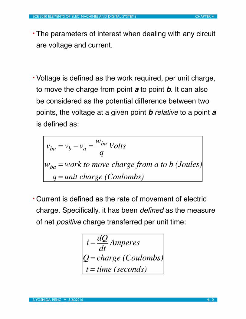
• The parameters of interest when dealing with any circuit are voltage and current.
• Voltage is defined as the work required, per unit charge, to move the charge from point a to point b. It can also be considered as the potential difference between two points, the voltage at a given point b relative to a point a is defined as:
vba = vb − va = wbaq
Volts
wba = work to move charge from a to b (Joules)q = unit charge (Coulombs)
• Current is defined as the rate of movement of electric charge. Specifically, it has been defined as the measure of net positive charge transferred per unit time:
i = dQdt Amperes
Q = charge (Coulombs)t = time (seconds)
ECE 3010 ELEMENTS OF ELEC. MACHINES AND DIGITAL SYSTEMS CHAPTER 4
B. YOSHIDA, P.ENG V1.3.2©2016 4-10

• Combining the concept of passive components with voltage and current results in: devices with two nodes; a voltage difference between the two nodes; and a current which enters one node and exits the other. Since voltage and current are vector quantities it is important to maintain the correct sign when performing any calculations. We will use the passive sign convention to label the parameters. The convention is that the current is assumed to enter the node of higher potential.
Passive
Element
+ v –
i
• The relationships between currents, and relationships between voltages, within a given electric circuit are governed Kirchhoff's Laws.
• Kirchhoff’s current law (KCL) requires that the algebraic sum of currents at a node must be zero.
ECE 3010 ELEMENTS OF ELEC. MACHINES AND DIGITAL SYSTEMS CHAPTER 4
B. YOSHIDA, P.ENG V1.3.2©2016 4-11
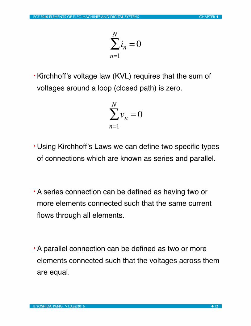
in = 0n=1
N
∑
• Kirchhoff’s voltage law (KVL) requires that the sum of voltages around a loop (closed path) is zero.
vn = 0n=1
N
∑
• Using Kirchhoff’s Laws we can define two specific types of connections which are known as series and parallel.
• A series connection can be defined as having two or more elements connected such that the same current flows through all elements.
• A parallel connection can be defined as two or more elements connected such that the voltages across them are equal.
ECE 3010 ELEMENTS OF ELEC. MACHINES AND DIGITAL SYSTEMS CHAPTER 4
B. YOSHIDA, P.ENG V1.3.2©2016 4-12

• Being able to identify these two types of connections is important since we can apply circuit simplification techniques to these types of connections. Making circuit representation simpler makes the analysis of their parameters simpler. It is important to realize that the concept of series and parallel do not refer to their graphical (pictorial) representations, but refer to their electrical configurations.
Example - Passive sign law with KVL and KCL• Given the following circuit, with the known parameters indicated, use KCL and KVL to determine the voltage and current parameters for all of the components.
+ 2V – – 3V +
!
"
# $
5A
–1A
Current and voltage relationships for specific devices
ECE 3010 ELEMENTS OF ELEC. MACHINES AND DIGITAL SYSTEMS CHAPTER 4
B. YOSHIDA, P.ENG V1.3.2©2016 4-13

• The relationship between the voltage and current associated with a resistor is governed by a linear relationship known as Ohm’s Law.
v(t) = Ri(t)v(t) = voltage (V)i(t) = current (A)
R = resistance (Ω)or for when dealing with dc values
V = RI
• Though both capacitors and inductors are passive devices, they are referred to as reactive devices. For reactive components their voltage and current characteristics will behave as functions of time.
• The capacitor is a passive energy storage device, which stores energy through the storage of electric charge. The amount of charge stored (i.e. the voltage) is related to the amount of time current (the flow of charge) is flowing into the capacitor.
ECE 3010 ELEMENTS OF ELEC. MACHINES AND DIGITAL SYSTEMS CHAPTER 4
B. YOSHIDA, P.ENG V1.3.2©2016 4-14
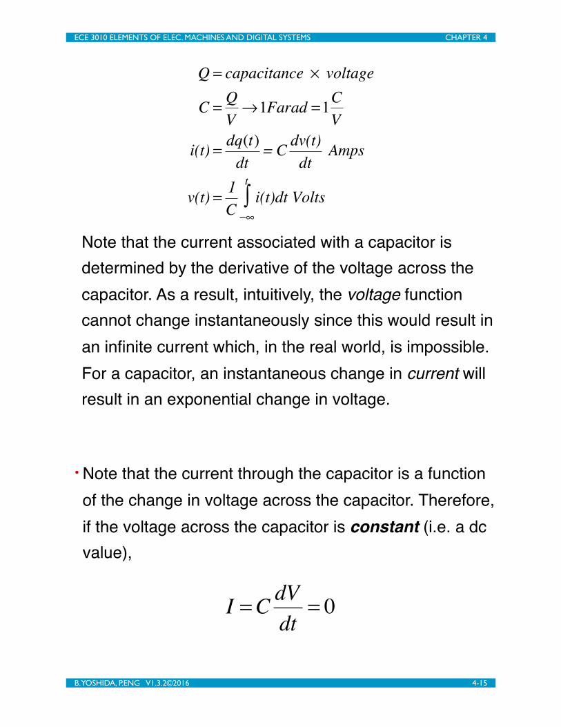
Q = capacitance × voltage
C = QV→1Farad =1C
V
i(t) = dq(t)dt
= C dv(t)dt
Amps
v(t) = 1C
i(t)dt Volts−∞
t
∫
Note that the current associated with a capacitor is determined by the derivative of the voltage across the capacitor. As a result, intuitively, the voltage function cannot change instantaneously since this would result in an infinite current which, in the real world, is impossible. For a capacitor, an instantaneous change in current will result in an exponential change in voltage.
• Note that the current through the capacitor is a function of the change in voltage across the capacitor. Therefore, if the voltage across the capacitor is constant (i.e. a dc value),
I =C dVdt
= 0
ECE 3010 ELEMENTS OF ELEC. MACHINES AND DIGITAL SYSTEMS CHAPTER 4
B. YOSHIDA, P.ENG V1.3.2©2016 4-15

• The inductor is another passive device which stores energy. The inductor stores energy via magnetic flux. Recall from basic physics, if a current flows through a wire, a magnetic field will be formed externally around the wire. Whenever a time varying magnetic flux passes through a loop of wire, a voltage will be induced on the loop.
• The basic inductor is a coil of wire which, by its nature, concentrates the magnetic flux in the vicinity of the coil. The magnetic field which is formed represents stored potential which is a voltage. The voltage and current associated with the inductor is related to the ‘capacity or size’ (measured in Henrys) of the inductor
v(t) = L di(t)dt
Volts
i(t) = 1L
v(t)dt Amps−∞
t
∫
The current in an inductor cannot change instantaneously. For an inductor, an instantaneous
ECE 3010 ELEMENTS OF ELEC. MACHINES AND DIGITAL SYSTEMS CHAPTER 4
B. YOSHIDA, P.ENG V1.3.2©2016 4-16

change in voltage will result in an exponential change in current.
• The voltage across the inductor is a function of the change in current through the inductor. Therefore, if the current through the inductor is constant (i.e. a dc value),
V = L dIdt
= 0
Power• The goal of any electric machine is to convert power between mechanical and electrical forms. Therefore we must be able to calculate the power absorbed by the electrical elements within our circuit. Power is defined as the rate of transfer, or absorption, of energy per unit time in a system.
p(t) = v(t)[units J / C] × i(t)[units C / s] = v(t)× i(t) J / s∴ p(t) = v(t)× i(t) W
ECE 3010 ELEMENTS OF ELEC. MACHINES AND DIGITAL SYSTEMS CHAPTER 4
B. YOSHIDA, P.ENG V1.3.2©2016 4-17
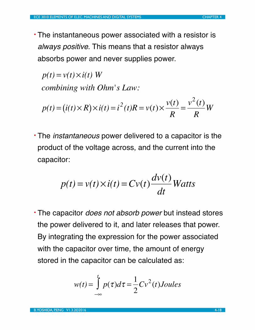
• The instantaneous power associated with a resistor is always positive. This means that a resistor always absorbs power and never supplies power.
p(t) = v(t)× i(t) Wcombining with Ohm's Law:
p(t) = i(t)× R( )× i(t) = i2 (t)R = v(t)× v(t)R
= v2 (t)R
W
• The instantaneous power delivered to a capacitor is the product of the voltage across, and the current into the capacitor:
p(t) = v(t)× i(t) =Cv(t)dv(t)dt
Watts
• The capacitor does not absorb power but instead stores the power delivered to it, and later releases that power. By integrating the expression for the power associated with the capacitor over time, the amount of energy stored in the capacitor can be calculated as:
w(t) = p(τ )dτ−∞
t
∫ = 12Cv2 (t)Joules
ECE 3010 ELEMENTS OF ELEC. MACHINES AND DIGITAL SYSTEMS CHAPTER 4
B. YOSHIDA, P.ENG V1.3.2©2016 4-18

• The inductor is another passive device which can store energy. The instantaneous power associated with an inductor can be calculated using:
p(t) = v(t)× i(t) = Li(t)di(t)dt
Watts
and the stored energy:
w(t) = p(τ )dτ−∞
t
∫ = 12Li2 (t)Joules
Example - Device specific behaviours and power calculations
• Given the solved circuit from the previous example determine what types of devices are represented by the unknown boxes.
+ 2V – – 3V +
!
"
# $
5A
–1A
– 1V +
5A
+
3V
–
–6A
ECE 3010 ELEMENTS OF ELEC. MACHINES AND DIGITAL SYSTEMS CHAPTER 4
B. YOSHIDA, P.ENG V1.3.2©2016 4-19

Equivalent circuits - Thevenin’s theorem
• We want to be able to represent an electric machine as a simple circuit. Thevenin’s theorem is a technique which can be applied to any electric device/circuit where we can analyze its external electrical behaviour from a pair of terminals, and then represent the device/circuit with a single voltage source and a single resistor.
• We can apply Thevenin’s theorem to any linear network which contains linear circuit elements, such as resistors, capacitors, inductors, and sources, to obtain a Thevenin equivalent circuit. The Thevenin equivalent circuit consists of an independent voltage source, Voc, and a series resistor, RTH.
MysteryDevice
+ –
????
Thevenin Equiv.
+–= Voc
Rth
ECE 3010 ELEMENTS OF ELEC. MACHINES AND DIGITAL SYSTEMS CHAPTER 4
B. YOSHIDA, P.ENG V1.3.2©2016 4-20
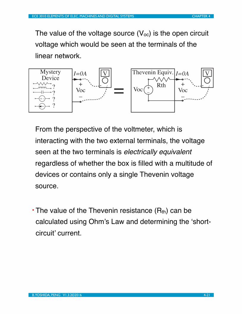
The value of the voltage source (Voc) is the open circuit voltage which would be seen at the terminals of the linear network.
MysteryDevice
+ –
????
Thevenin Equiv.
+–= Voc
Rth
VI=0A VI=0A
+Voc
–
+Voc
–
From the perspective of the voltmeter, which is interacting with the two external terminals, the voltage seen at the two terminals is electrically equivalent regardless of whether the box is filled with a multitude of devices or contains only a single Thevenin voltage source.
• The value of the Thevenin resistance (Rth) can be calculated using Ohm’s Law and determining the ‘short-circuit’ current.
ECE 3010 ELEMENTS OF ELEC. MACHINES AND DIGITAL SYSTEMS CHAPTER 4
B. YOSHIDA, P.ENG V1.3.2©2016 4-21

MysteryDevice
+ –
????
Thevenin Equiv.
+–= Voc
Rth
AI!0A AI!0A
+0V–
+0V–
• At this point we have enough information to be able to model a dc electric machine, and by applying some basic circuit analysis techniques we can analyze the terminal behaviour of the machine.
DC Machines• DC machines use dc voltages and currents to establish the required magnetic fields, and therefore accept or provide dc values at its terminals.
• The actual magnetic fields are created using coils of wire which form electromagnets. The normal terminology when dealing with dc machines uses the term field winding - which is the non-changing portion of
ECE 3010 ELEMENTS OF ELEC. MACHINES AND DIGITAL SYSTEMS CHAPTER 4
B. YOSHIDA, P.ENG V1.3.2©2016 4-22

the machine - for the stator winding/magnet, and the armature winding for the rotor winding/magnet.
• When using a dc machine as a motor we will be powering the armature winding to allow it to form an electromagnet, and it will operate as previously described. However, when using the same dc machine as a generator we will mechanically move the rotor through the magnetic field of the field winding and induce a current to flow in the rotor.
• To understand how the dc machine acts as a generator, recall from basic physics that when a current flows along a wire a magnetic field is established around the wire. The direction of current flow and the direction of the magnetic field are related via the right hand rule, where if the thumb of the right hand is in the direction of current flow, the direction of the magnetic field will be indicated by the direction of the four fingers.
ECE 3010 ELEMENTS OF ELEC. MACHINES AND DIGITAL SYSTEMS CHAPTER 4
B. YOSHIDA, P.ENG V1.3.2©2016 4-23

i(t)
+
MagneticField
This phenomena also works in ‘reverse.’ If the wire is moved through an existing magnetic field, a current will be induced by the magnetic field to flow in the wire. When using the electric machine as a generator we are mechanically moving a coil of wire through a fixed magnetic field and are able to draw electrical energy from the moving armature.
Machine construction• The basic electric machine consists of a stator and a rotor. The stator is constructed as a coil of wire. We can pass a current through two coils of wire, which will form a magnetic field between them, where we can place the rotor.
ECE 3010 ELEMENTS OF ELEC. MACHINES AND DIGITAL SYSTEMS CHAPTER 4
B. YOSHIDA, P.ENG V1.3.2©2016 4-24

S N S N
• The rotor also consists of a coil of wire which will move through the magnetic field provided by the field winding on the stator. To simplify the initial description of the rotor, first consider a single loop of wire, rather than a coil consisting of many loops.
S N S N
+ einduced V –
a b
This can be further simplified by only considering one side of the loop - a single straight piece of wire passing through the magnetic field. From basic physics we know that moving a single conductor of length l at speed v
ECE 3010 ELEMENTS OF ELEC. MACHINES AND DIGITAL SYSTEMS CHAPTER 4
B. YOSHIDA, P.ENG V1.3.2©2016 4-25

with the wire ‘cutting’ the flux lines of a magnetic field of flux density B will result in a voltage on the wire of eab = Blv Volts.
S N S N
a
b
B
l
v
ø
The implication of this is that regardless of whether we are using the machine as a motor or generator, as long as the rotor / armature winding is moving through the magnetic field of the stator / field winding, we will have a voltage on the armature coil.
As the single side of a coil moves through the centre of the stator the velocity v of the wire will be positive half the time and negative for the remaining time which means that the voltage induced on the wire will look like
ECE 3010 ELEMENTS OF ELEC. MACHINES AND DIGITAL SYSTEMS CHAPTER 4
B. YOSHIDA, P.ENG V1.3.2©2016 4-26

eab V
ø
The problem with this is that the goal of the dc machine acting as a generator is to have dc values at its terminals, and not a constant magnitude with an alternating sign. This problem can be solved by using a brush-commutator such that the terminal voltage taken from a generator, or applied to a motor, are constant.
S N S N
+ einduced V –
The resulting voltage measured at the two terminals will appear as
ECE 3010 ELEMENTS OF ELEC. MACHINES AND DIGITAL SYSTEMS CHAPTER 4
B. YOSHIDA, P.ENG V1.3.2©2016 4-27

eab V
ø
The points of zero volts can be virtually eliminated through optimizing the construction of the machine.
Expressions for the induced voltage and developed torque
• The torque and rotational speed associated with an electric machine can be described via:
T =Kφ iaT = torque (Nm)Kφ = machine const.ia = armature current(Amps)
Ea =KφωmEa = armature voltage (V )Kφ = machine const.ωm = armature speed(radian / s)
ECE 3010 ELEMENTS OF ELEC. MACHINES AND DIGITAL SYSTEMS CHAPTER 4
B. YOSHIDA, P.ENG V1.3.2©2016 4-28

• The strength of the stator magnetic field can be adjusted by changing the current passing through its windings (the field current), however this magnetic field can also be generated by using permanent magnets in which case the field will be a fixed value.
• If an electromagnet is used it is important to be aware that the strength of the magnetic field is not linear. There will be a small amount of residual magnetism without any current flowing, and there is an upper limit where the electromagnet will reach saturation. Generally this nonlinear nature is described via a no-load saturation curve which relates the armature voltage to the field current.
Ea V
If A
ECE 3010 ELEMENTS OF ELEC. MACHINES AND DIGITAL SYSTEMS CHAPTER 4
B. YOSHIDA, P.ENG V1.3.2©2016 4-29
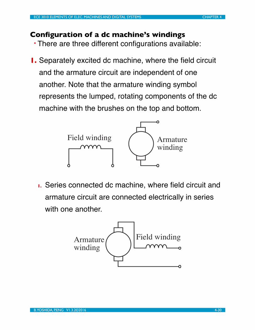
Configuration of a dc machine’s windings• There are three different configurations available:
1. Separately excited dc machine, where the field circuit and the armature circuit are independent of one another. Note that the armature winding symbol represents the lumped, rotating components of the dc machine with the brushes on the top and bottom.
Field winding Armaturewinding
1. Series connected dc machine, where field circuit and armature circuit are connected electrically in series with one another.
Field windingArmaturewinding
ECE 3010 ELEMENTS OF ELEC. MACHINES AND DIGITAL SYSTEMS CHAPTER 4
B. YOSHIDA, P.ENG V1.3.2©2016 4-30

2. Shunt connected dc machine, where the field circuit and armature circuit are electrically connected in parallel.
Armaturewinding
Field winding
DC machine equivalent circuit model• By applying Thevenin’s theorem we can simplify the rotor circuit into its Thevenin equivalent voltage source and resistor. By representing the resistance of the wire in the stator windings as resistors we have the following:
+
Ea–
Ra
Rf
+ Vf –
If
+
Vt
–
Ia
• In normal operations we want to control the speed and torque characteristics of the electric machine. This can be done by controlling Ea which is a function of If, and Ia
ECE 3010 ELEMENTS OF ELEC. MACHINES AND DIGITAL SYSTEMS CHAPTER 4
B. YOSHIDA, P.ENG V1.3.2©2016 4-31
which is in turn controlled by Ea. As a result, we normally add a potentiometer in the field circuit to control the current in the field winding.
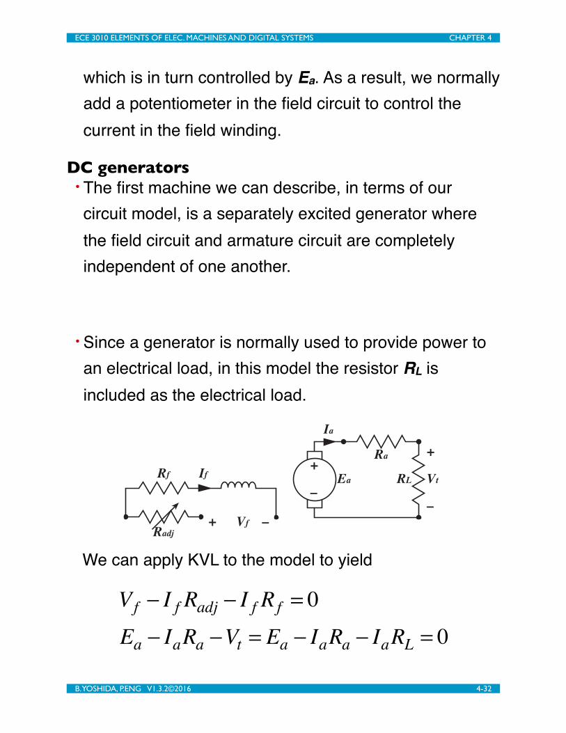
DC generators• The first machine we can describe, in terms of our circuit model, is a separately excited generator where the field circuit and armature circuit are completely independent of one another.
• Since a generator is normally used to provide power to an electrical load, in this model the resistor RL is included as the electrical load.
+
Ea
–
Ra
Rf
+ Vf –
If
+
Vt
–
Ia
Radj
RL
We can apply KVL to the model to yield
Vf − I f Radj − I f Rf = 0Ea − IaRa −Vt = Ea − IaRa − IaRL = 0
ECE 3010 ELEMENTS OF ELEC. MACHINES AND DIGITAL SYSTEMS CHAPTER 4
B. YOSHIDA, P.ENG V1.3.2©2016 4-32

We are able to adjust the output voltage, Vt, by controlling the magnetic field of the field circuit, or via the speed of rotation of the armature, the ωm term.
• The dc generator can also be configured in a shunt configuration, and the circuit described using KVL, and KCL
+
Ea
–
Ra
Rf +
Vf
–
If
+
Vt
–
Ia
Radj IL
RL
Ea − IaRa −Vt = 0Ea = Kφωm
Vt − I f Radj − I f Rf = 0Ia − I f − IL = 0
If we consider the no-load configuration, and apply KVL to the loop, we have
ECE 3010 ELEMENTS OF ELEC. MACHINES AND DIGITAL SYSTEMS CHAPTER 4
B. YOSHIDA, P.ENG V1.3.2©2016 4-33
+
Ea
–
Ra
Rf +
Vf
–
If
+
Vt
–
Ia
Radj IL
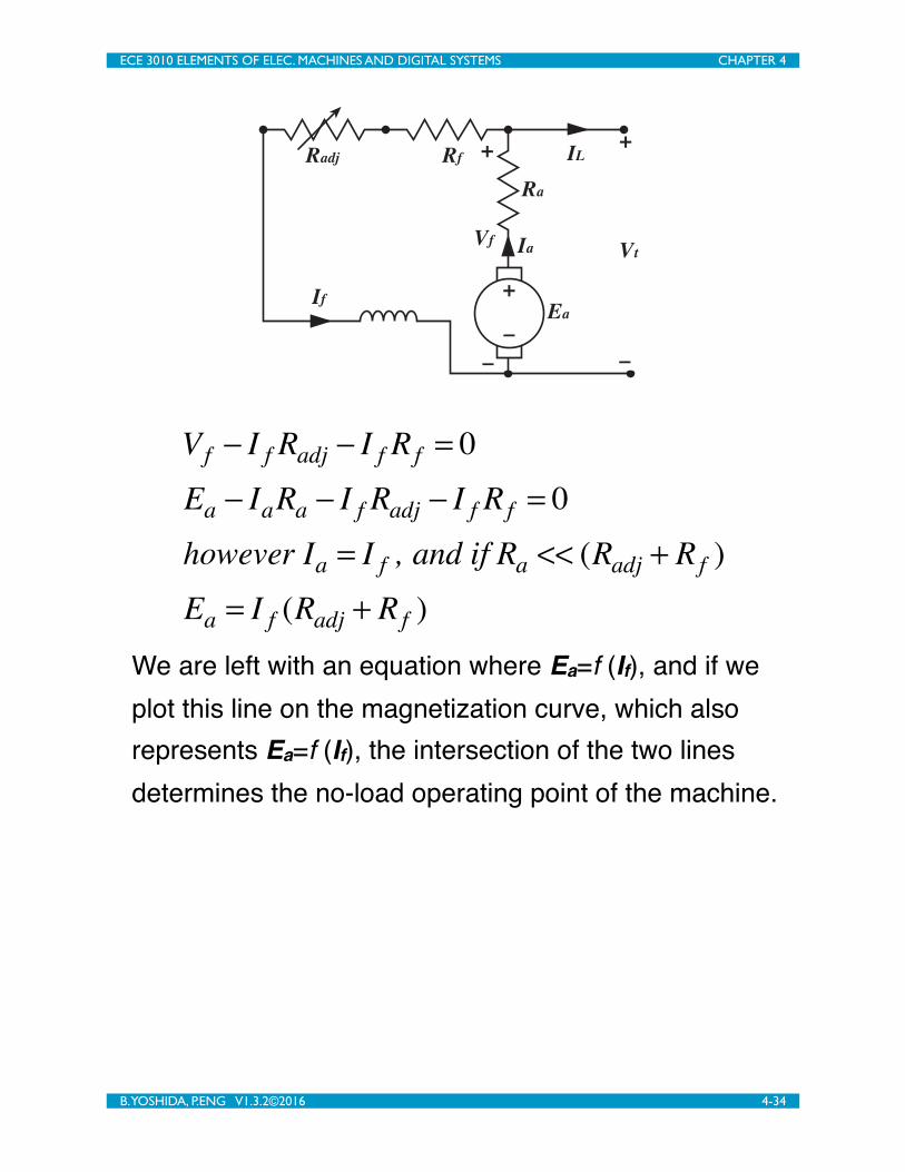
Vf − I f Radj − I f Rf = 0Ea − IaRa − I f Radj − I f Rf = 0however Ia = I f , and if Ra << (Radj + Rf )Ea = I f (Radj + Rf )
We are left with an equation where Ea=f (If), and if we plot this line on the magnetization curve, which also represents Ea=f (If), the intersection of the two lines determines the no-load operating point of the machine.
ECE 3010 ELEMENTS OF ELEC. MACHINES AND DIGITAL SYSTEMS CHAPTER 4
B. YOSHIDA, P.ENG V1.3.2©2016 4-34

Ea=(Rf1+Radj1)If
300
200
100
0
21.61.20.80.40
Ea V
If A
Ea=(Rf2+Radj2)If(Rf2+Radj2)>(Rf1+Radj1)
We can extend this analysis to cover the case with an attached load if we consider that we have
Ea − IaRa −Vt = 0Vt − I f Radj − I f Rf = 0∴Ea − IaRa − I f Radj − I f Rf = 0Ea = (Radj + Rf )I f + IaRa
ECE 3010 ELEMENTS OF ELEC. MACHINES AND DIGITAL SYSTEMS CHAPTER 4
B. YOSHIDA, P.ENG V1.3.2©2016 4-35

300
200
100
0
21.61.20.80.40
Ea V
If A
Ea=(Rf1+Radj1)If
Ea=(Rf1+Radj1)If+RaIa
No-loadoperating point
Actualoperating point
Figure 4.34 – Operating point with load.
Example – DC machine• Given a dc machine with the following parameters:
• rated operating parameters: 10kW, 250V, 1000rpm
• electrical parameters: Ra = 0.2Ω, Rf = 133Ω
• magnetization curve (@1000rpm):
If (A)
Ea(V)
0 0.1 0.2 0.3 0.4 0.5 0.75 1.0 1.5 2.0
10 40 80 120 150 170 200 220 245 263
If the machine is connected in a shunt configuration and operated as a generator at the rated speed, determine:
ECE 3010 ELEMENTS OF ELEC. MACHINES AND DIGITAL SYSTEMS CHAPTER 4
B. YOSHIDA, P.ENG V1.3.2©2016 4-36

• What is the no-load output voltage if there is no field current?
• What is needed for the machine to have a no-load output voltage of 245V?
• What is needed for the machine to have a no-load output voltage of 250V?
Table 1
Ia 0 0.1 0.2 0.3 0.4 0.5 0.75 1 1.5 2
191 194.6 198.2 201.8 205.4 209 218 227 245 263
Ea 10 40 80 120 150 170 200 220 245 263
Ea
0
75
150
225
300
If0 0.5 1 1.5 2
Ea
1
263− 2452.0 −1.5
x +191= y ⇒ 36I f +191= Ea
for Ea = 250V = 36I f +191⇒ I f = 250 −19136
=1.63A
ECE 3010 ELEMENTS OF ELEC. MACHINES AND DIGITAL SYSTEMS CHAPTER 4
B. YOSHIDA, P.ENG V1.3.2©2016 4-37

⇒ Radj + Rf = VtI f
⇒ Radj = 2501.63
−133 = 20.37Ω
• What is the no-load output voltage if the machine is rotated at 800rpm without a field control resistor (Radj = 0Ω)?
300
200
100
0
21.61.20.80.40
Ea V
If A
1000rpmMagnetization
curve
800rpmMagnetizationcurve
Ea=133If
ECE 3010 ELEMENTS OF ELEC. MACHINES AND DIGITAL SYSTEMS CHAPTER 4
B. YOSHIDA, P.ENG V1.3.2©2016 4-38

• What rotational speed is required to have a no-load output voltage of 200V without a control resistor (Radj=0Ω)?
245 = Kφ100060
2π
200 = Kφxrpm60
2π
∴ xrpm = 816.32rpm
DC motor• DC motors follow a similar form to the dc generators. They can be configured as separately excited, shunt, and series implementations.
ECE 3010 ELEMENTS OF ELEC. MACHINES AND DIGITAL SYSTEMS CHAPTER 4
B. YOSHIDA, P.ENG V1.3.2©2016 4-39
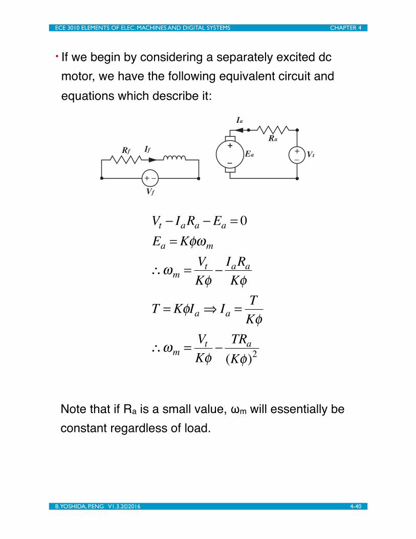
• If we begin by considering a separately excited dc motor, we have the following equivalent circuit and equations which describe it:
+
Ea–
Ra
Rf
Vf
IfVt
Ia
+ –
+
–
Vt − IaRa −Ea = 0Ea = Kφωm
∴ωm = VtKφ
− IaRaKφ
T = KφIa ⇒ Ia = TKφ
∴ωm = VtKφ
− TRa(Kφ)2
Note that if Ra is a small value, ωm will essentially be constant regardless of load.
ECE 3010 ELEMENTS OF ELEC. MACHINES AND DIGITAL SYSTEMS CHAPTER 4
B. YOSHIDA, P.ENG V1.3.2©2016 4-40

• For a separately excited dc motor we can control the speed by controlling Vt, or controlling the Kϕ terms which are controlled via Vf or the resistance of the field circuit (Rf+Radj).
• Series dc motor
+
Ea–
Ra
Ia
Vt+
–
RadjRf
Mechanical
Load
ECE 3010 ELEMENTS OF ELEC. MACHINES AND DIGITAL SYSTEMS CHAPTER 4
B. YOSHIDA, P.ENG V1.3.2©2016 4-41
Note that the speed is inversely proportional to the torque. This means that at low speeds we have a very large torque.
• The final configuration of a shunt motor can be analyzed using techniques similar to the shunt generator analysis which was previously examined.
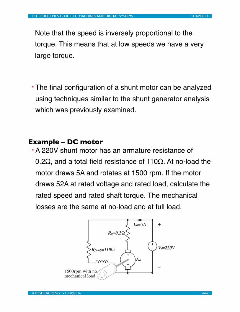
Example – DC motor• A 220V shunt motor has an armature resistance of 0.2Ω, and a total field resistance of 110Ω. At no-load the motor draws 5A and rotates at 1500 rpm. If the motor draws 52A at rated voltage and rated load, calculate the rated speed and rated shaft torque. The mechanical losses are the same at no-load and at full load.
i(t)
+
MagneticField
Inl=5A
Ra=0.2Ω
Rf+adj=110Ω
+
Vt=220V
–
+ Ea–
1500rpm with nomechanical load
+–
ECE 3010 ELEMENTS OF ELEC. MACHINES AND DIGITAL SYSTEMS CHAPTER 4
B. YOSHIDA, P.ENG V1.3.2©2016 4-42
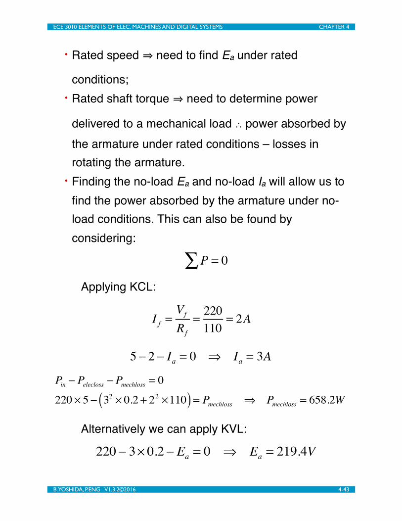
• Rated speed ⇒ need to find Ea under rated
conditions;• Rated shaft torque ⇒ need to determine power
delivered to a mechanical load ∴ power absorbed by the armature under rated conditions – losses in rotating the armature.
• Finding the no-load Ea and no-load Ia will allow us to find the power absorbed by the armature under no-load conditions. This can also be found by considering:
P = 0∑Applying KCL:
I f =Vf
Rf
= 220110
= 2A
5 − 2 − Ia = 0 ⇒ Ia = 3A
Pin − Pelecloss − Pmechloss = 0
220 × 5 − 32 × 0.2 + 22 ×110( ) = Pmechloss ⇒ Pmechloss = 658.2W
Alternatively we can apply KVL:
220 − 3× 0.2 − Ea = 0 ⇒ Ea = 219.4V
ECE 3010 ELEMENTS OF ELEC. MACHINES AND DIGITAL SYSTEMS CHAPTER 4
B. YOSHIDA, P.ENG V1.3.2©2016 4-43

The power absorbed by the armature (while not driving a mechanical load) are:
Pa = EaIa = 219.4 × 3= 658.2W
This is the power required just to turn the armature (i.e. overcome the mechanical losses in the armature). The same result as obtained previously.
• Finding the rated-load Ea and rated-load Ia will allow us to find the power absorbed by the armature under full-load conditions. This can also be found by considering:
i(t)
+
MagneticField
Inl=5A
Ra=0.2Ω
Rf+adj=110Ω
+
Vt=220V
–
+ Ea–
1500rpm with nomechanical load
+–
Iratedload=52A
Ra=0.2Ω
Rf+adj=110Ω
+
Vt=220V
–
+ Ea–
? rpm withmechanical load
+–
I f =Vf
Rf
= 220110
= 2A
52 − 2 − Ia = 0 ⇒ Ia = 50A
ECE 3010 ELEMENTS OF ELEC. MACHINES AND DIGITAL SYSTEMS CHAPTER 4
B. YOSHIDA, P.ENG V1.3.2©2016 4-44

Pin − Pelecloss − Parmature = 0
220 × 52 − 502 × 0.2 + 22 ×110( ) = Parmature ⇒ Parmature = 10500WPload = Parmature − Pmechloss = 10500 − 658.2 = 9841.8W
• Finding the rated-torque requires finding the rated speed. This can also be found by considering:
220 − 50 × 0.2 − Ea( fullload ) = 0 ⇒ Ea( fullload ) = 210VEa(noload )
Ea( fullload )
= 219.4210
=Kφωm(noload )
Kφωm( fullload )
=150060 2π
ωm( fullload )
⇒ ωm( fullload ) = 150.35rad / s
T = Pω
= 9148.8150.35
= 65.46Nm
ConclusionThis chapter provided a review of basic circuit concepts and how they can be applied to the study of dc machines. The following objectives were met:
1. Understand the concepts of basic circuit elements, parameters, and topologies.
2. Be able to apply KVL, KCL, and Ohm’s Law to analyze a circuit to solve for any voltage and current parameters.
ECE 3010 ELEMENTS OF ELEC. MACHINES AND DIGITAL SYSTEMS CHAPTER 4
B. YOSHIDA, P.ENG V1.3.2©2016 4-45

3. Be able to determine the power associated with a circuit element.
4. Understand the basic operation and configuration of a dc machine.
5. Be able to analyze a dc electric machine and determine its external parameters both electrical and mechanical.
ECE 3010 ELEMENTS OF ELEC. MACHINES AND DIGITAL SYSTEMS CHAPTER 4
B. YOSHIDA, P.ENG V1.3.2©2016 4-46