Embed Size (px)
Citation preview
Chapter 4: EtherChannel and HSRP
CCNA Routing and Switching
Scaling Networks
2© 2016 Cisco and/or its affiliates. All rights reserved. Cisco Confidential
4.1 Link Aggregation Concepts
• Explain link aggregation operation in a switched LAN environment.
• Describe link aggregation.
• Describe EtherChannel technology.
4.2 Link Aggregation Configuration
• Implement link aggregation to improve performance on high-traffic switch links.
• Configure link aggregation.
• Troubleshoot a link aggregation implementation.
4.3 First Hop Redundancy Protocols (Read Only)
• Implement HSRP
• Explain the purpose and operation of first hop redundancy protocols.
• Explain how HSRP operates.
Chapter 4 - Sections & Objectives

3© 2016 Cisco and/or its affiliates. All rights reserved. Cisco Confidential
4.1 Link Aggregation Concepts

4© 2016 Cisco and/or its affiliates. All rights reserved. Cisco Confidential
It is possible to combine the number of physical links between switches to increase the overall
speed of switch-to-switch communication.
• STP will block redundant links to prevent routing loops.
Link Aggregation
Introduction to Link Aggregation
Redundant Links with STP (by default blocked)

5© 2016 Cisco and/or its affiliates. All rights reserved. Cisco Confidential
Link Aggregation
Advantages of EtherChannel
Most configuration tasks can be done on
the EtherChannel interface instead of on
each individual port.
EtherChannel relies on existing switch
ports.
Load balancing takes place between links
that are part of the same EtherChannel.
EtherChannel creates an aggregation that
is seen as one logical link.
EtherChannel provides redundancy
because the overall link is seen as one
logical connection.
6© 2016 Cisco and/or its affiliates. All rights reserved. Cisco Confidential
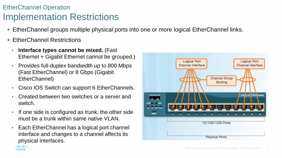
EtherChannel groups multiple physical ports into one or more logical EtherChannel links.
EtherChannel Operation
Implementation Restrictions
EtherChannel Restrictions
• Interface types cannot be mixed. (Fast
Ethernet + Gigabit Ethernet cannot be grouped.)
• Provides full-duplex bandwidth up to 800 Mbps
(Fast EtherChannel) or 8 Gbps (Gigabit
EtherChannel)
• Cisco IOS Switch can support 6 EtherChannels.
• Created between two switches or a server and
switch.
• If one side is configured as trunk, the other side
must be a trunk within same native VLAN.
• Each EtherChannel has a logical port channel
interface and changes to a channel affects its
physical interfaces.
7© 2016 Cisco and/or its affiliates. All rights reserved. Cisco Confidential
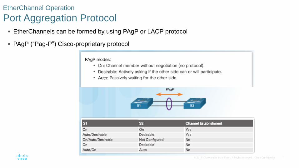
EtherChannels can be formed by using PAgP or LACP protocol
PAgP (“Pag-P”) Cisco-proprietary protocol
EtherChannel Operation
Port Aggregation Protocol

8© 2016 Cisco and/or its affiliates. All rights reserved. Cisco Confidential
LACP multivendor environment
EtherChannel Operation
Link Aggregation Control Protocol

9© 2016 Cisco and/or its affiliates. All rights reserved. Cisco Confidential
4.2 Link Aggregation Configuration
10© 2016 Cisco and/or its affiliates. All rights reserved. Cisco Confidential
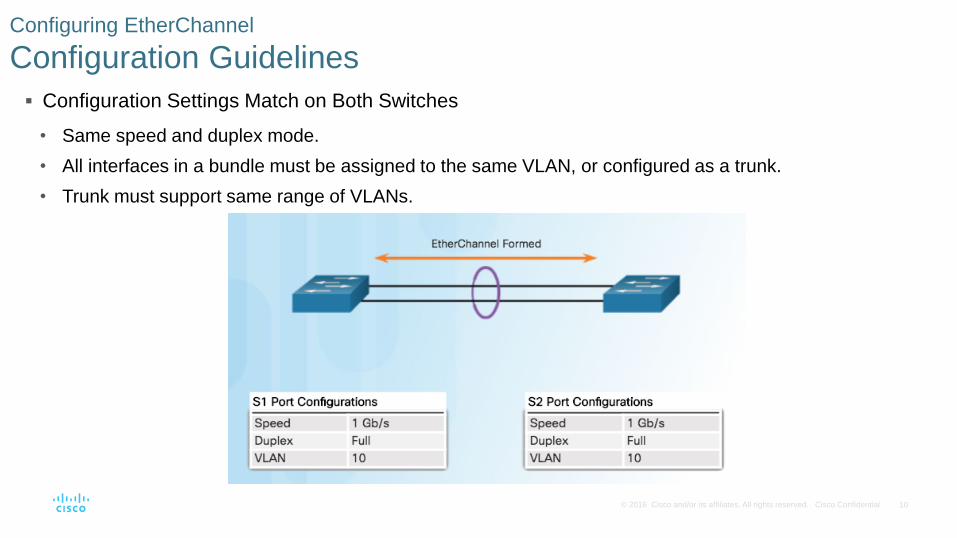
Configuration Settings Match on Both Switches
• Same speed and duplex mode.
• All interfaces in a bundle must be assigned to the same VLAN, or configured as a trunk.
• Trunk must support same range of VLANs.
Configuring EtherChannel
Configuration Guidelines

11© 2016 Cisco and/or its affiliates. All rights reserved. Cisco Confidential
If Configuration Settings Do Not Match
EtherChannel not formed between S1 and S2
Configuring EtherChannel
Configuration Guidelines (Cont.)
Note: When changing settings, configure them in port
channel interface configuration mode. The configuration
applied to the port channel interface also affects the
individual interfaces.

12© 2016 Cisco and/or its affiliates. All rights reserved. Cisco Confidential
This configuration creates EtherChannel with LACP and configures trunking.
• Step 1: Specify the interfaces that compose the EtherChannel group.
• Step 2: Create the port channel interface with the channel-group command in active mode. (Channel
group number needs to be selected.)
• Step 3: Change Layer 2 settings in port channel interface configuration mode.
Configuring EtherChannel
Configuring Interfaces
13© 2016 Cisco and/or its affiliates. All rights reserved. Cisco Confidential
Verifying and Troubleshooting EtherChannel
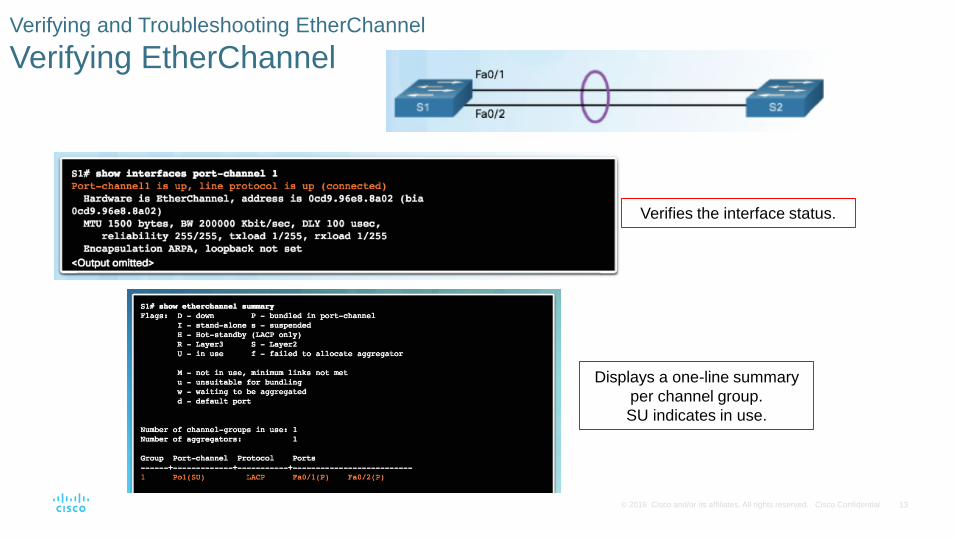
Verifying EtherChannel
Verifies the interface status.
Displays a one-line summary
per channel group.
SU indicates in use.
14© 2016 Cisco and/or its affiliates. All rights reserved. Cisco Confidential
Verifying and Troubleshooting EtherChannel
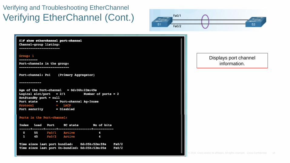
Verifying EtherChannel (Cont.)
Displays port channel
information.
15© 2016 Cisco and/or its affiliates. All rights reserved. Cisco Confidential
Verifying and Troubleshooting EtherChannel
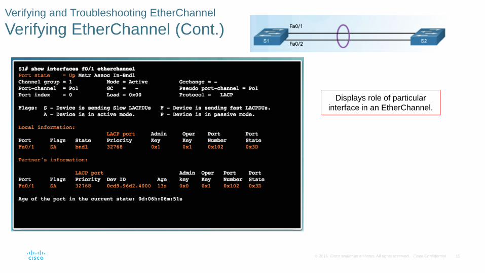
Verifying EtherChannel (Cont.)
Displays role of particular
interface in an EtherChannel.
16© 2016 Cisco and/or its affiliates. All rights reserved. Cisco Confidential
Verifying and Troubleshooting EtherChannel
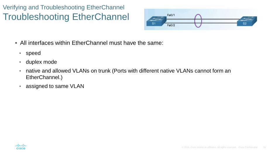
Troubleshooting EtherChannel
All interfaces within EtherChannel must have the same:
• speed
• duplex mode
• native and allowed VLANs on trunk (Ports with different native VLANs cannot form an
EtherChannel.)
• assigned to same VLAN

17© 2016 Cisco and/or its affiliates. All rights reserved. Cisco Confidential
Verifying and Troubleshooting EtherChannel
Troubleshooting EtherChannel (Cont.)
Output indicates that the
EtherChannel is down (SD).

18© 2016 Cisco and/or its affiliates. All rights reserved. Cisco Confidential
Verifying and Troubleshooting EtherChannel
Troubleshooting EtherChannel (Cont.)
Incompatible PAgP modes
configured on S1 and S2.
19© 2016 Cisco and/or its affiliates. All rights reserved. Cisco Confidential
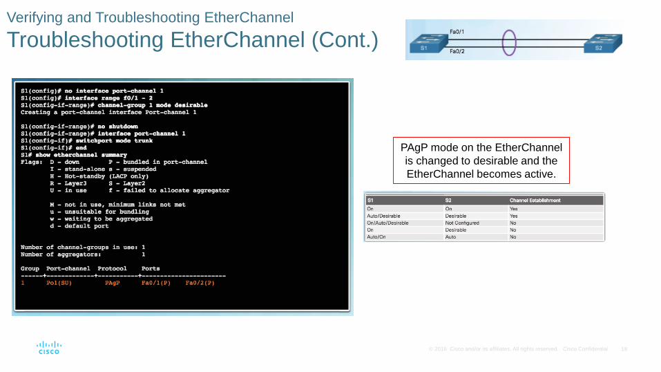
Verifying and Troubleshooting EtherChannel
Troubleshooting EtherChannel (Cont.)
PAgP mode on the EtherChannel
is changed to desirable and the
EtherChannel becomes active.
20© 2016 Cisco and/or its affiliates. All rights reserved. Cisco Confidential
4.3 First Hop Redundancy Protocols(Read Only)
21© 2016 Cisco and/or its affiliates. All rights reserved. Cisco Confidential
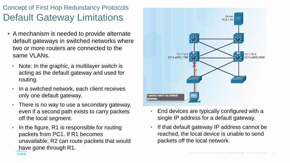
Concept of First Hop Redundancy Protocols
Default Gateway Limitations
A mechanism is needed to provide alternate
default gateways in switched networks where
two or more routers are connected to the
same VLANs.
• Note: In the graphic, a multilayer switch is
acting as the default gateway and used for
routing.
• In a switched network, each client receives
only one default gateway.
• There is no way to use a secondary gateway,
even if a second path exists to carry packets
off the local segment.
• In the figure, R1 is responsible for routing
packets from PC1. If R1 becomes
unavailable, R2 can route packets that would
have gone through R1.
• End devices are typically configured with a
single IP address for a default gateway.
• If that default gateway IP address cannot be
reached, the local device is unable to send
packets off the local network.
22© 2016 Cisco and/or its affiliates. All rights reserved. Cisco Confidential
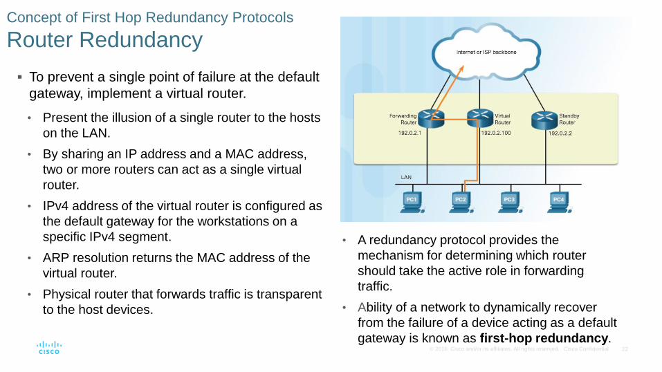
Concept of First Hop Redundancy Protocols
Router Redundancy
To prevent a single point of failure at the default
gateway, implement a virtual router.
• Present the illusion of a single router to the hosts
on the LAN.
• By sharing an IP address and a MAC address,
two or more routers can act as a single virtual
router.
• IPv4 address of the virtual router is configured as
the default gateway for the workstations on a
specific IPv4 segment.
• ARP resolution returns the MAC address of the
virtual router.
• Physical router that forwards traffic is transparent
to the host devices.
• A redundancy protocol provides the
mechanism for determining which router
should take the active role in forwarding
traffic.
• Ability of a network to dynamically recover
from the failure of a device acting as a default
gateway is known as first-hop redundancy.
23© 2016 Cisco and/or its affiliates. All rights reserved. Cisco Confidential
Concept of First Hop Redundancy Protocols
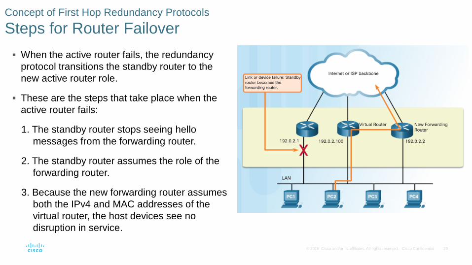
Steps for Router Failover
When the active router fails, the redundancy
protocol transitions the standby router to the
new active router role.
These are the steps that take place when the
active router fails:
1. The standby router stops seeing hello
messages from the forwarding router.
2. The standby router assumes the role of the
forwarding router.
3. Because the new forwarding router assumes
both the IPv4 and MAC addresses of the
virtual router, the host devices see no
disruption in service.
24© 2016 Cisco and/or its affiliates. All rights reserved. Cisco Confidential
Concept of First Hop Redundancy Protocols
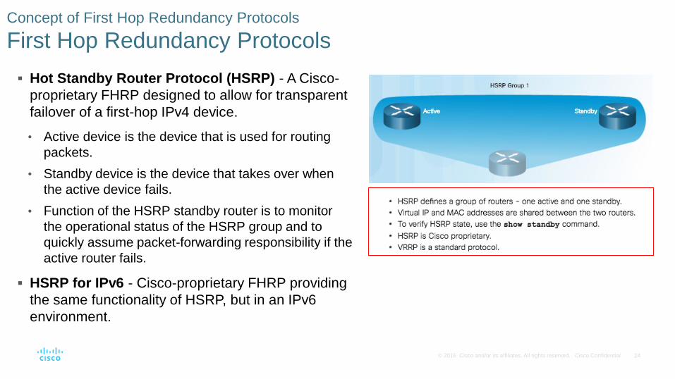
First Hop Redundancy Protocols
Hot Standby Router Protocol (HSRP) - A Cisco-
proprietary FHRP designed to allow for transparent
failover of a first-hop IPv4 device.
• Active device is the device that is used for routing
packets.
• Standby device is the device that takes over when
the active device fails.
• Function of the HSRP standby router is to monitor
the operational status of the HSRP group and to
quickly assume packet-forwarding responsibility if the
active router fails.
HSRP for IPv6 - Cisco-proprietary FHRP providing
the same functionality of HSRP, but in an IPv6
environment.
25© 2016 Cisco and/or its affiliates. All rights reserved. Cisco Confidential
Concept of First Hop Redundancy Protocols
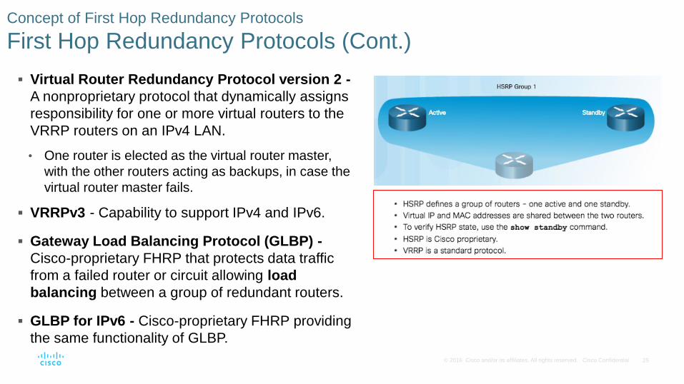
First Hop Redundancy Protocols (Cont.)
Virtual Router Redundancy Protocol version 2 -
A nonproprietary protocol that dynamically assigns
responsibility for one or more virtual routers to the
VRRP routers on an IPv4 LAN.
• One router is elected as the virtual router master,
with the other routers acting as backups, in case the
virtual router master fails.
VRRPv3 - Capability to support IPv4 and IPv6.
Gateway Load Balancing Protocol (GLBP) -
Cisco-proprietary FHRP that protects data traffic
from a failed router or circuit allowing load
balancing between a group of redundant routers.
GLBP for IPv6 - Cisco-proprietary FHRP providing
the same functionality of GLBP.
26© 2016 Cisco and/or its affiliates. All rights reserved. Cisco Confidential
HSRP Operations
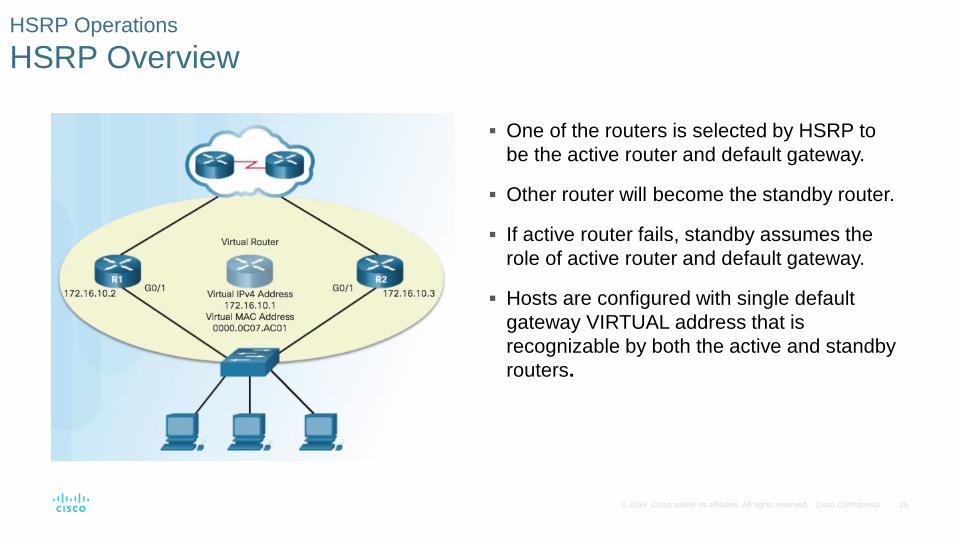
HSRP Overview
One of the routers is selected by HSRP to
be the active router and default gateway.
Other router will become the standby router.
If active router fails, standby assumes the
role of active router and default gateway.
Hosts are configured with single default
gateway VIRTUAL address that is
recognizable by both the active and standby
routers.

27© 2016 Cisco and/or its affiliates. All rights reserved. Cisco Confidential
HSRP Operations
HSRP Priority and Preemption
Role of active and standby routers determined by election process.
By default, the router with the numerically highest IPv4 address is elected as the active router.
Control HSRP election with priority and do not use highest address.
HSRP Priority
• Used to determine active router.
• Default HSRP priority is 100.
• Range is 0 to 255 and router with highest priority will become active.
• Use the standby priority interface command.
HSRP Preemption
• Preemption - ability of HSRP router to trigger the re-election process.
• To force a new HSRP election process, preemption must be enabled using standby preempt interface.
• A router that comes online with the a higher priority will become the active router.
28© 2016 Cisco and/or its affiliates. All rights reserved. Cisco Confidential
HSRP Operations
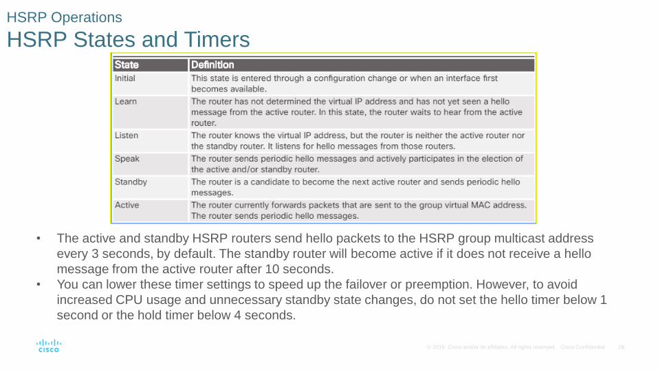
HSRP States and Timers
• The active and standby HSRP routers send hello packets to the HSRP group multicast address
every 3 seconds, by default. The standby router will become active if it does not receive a hello
message from the active router after 10 seconds.
• You can lower these timer settings to speed up the failover or preemption. However, to avoid
increased CPU usage and unnecessary standby state changes, do not set the hello timer below 1
second or the hold timer below 4 seconds.

29© 2016 Cisco and/or its affiliates. All rights reserved. Cisco Confidential
4.4 Chapter Summary

30© 2016 Cisco and/or its affiliates. All rights reserved. Cisco Confidential
Conclusion
Chapter 4: EtherChannel and HSRP
EtherChannel and how to encompass both the PAgP-based and the LACP-based link
aggregation methods
EtherChannel technologies and the various means available to implement them
The configuration, verification, and troubleshooting of EtherChannel