Embed Size (px)
Citation preview
Pfleeger and Atlee, Software Engineering: Theory and Practice, edited by B. Cheng,
Chapter 4.
Chapter 4 Objectives
• Eliciting requirements from the customers• Modeling requirements• Reviewing requirements to ensure their
quality• Documenting requirements for use by the
design and test teams

Pfleeger and Atlee, Software Engineering: Theory and Practice, edited by B. Cheng,
Chapter 4.
4.1 The Requirements Process
• A requirement is an expression of desired behavior
• A requirement deals with– objects or entities– the state they can be in– functions that are performed to change states or
object characteristics• Requirements focus on the customer needs,
not on the solution or implementation– designate what behavior, without saying how that
behavior will be realized

Pfleeger and Atlee, Software Engineering: Theory and Practice, edited by B. Cheng,
Chapter 4.
4.1 The Requirements ProcessSidebar 4.1 Why Are Requirements Important?• Top factors that caused project to fail
– Incomplete requirements– Lack of user involvement– Unrealistic expectations– Lack of executive support– Changing requirements and specifications– Lack of planning– System no longer needed
• Some part of the requirements process is involved in almost all of these causes
• Requirements error can be expensive if not detected early

Pfleeger and Atlee, Software Engineering: Theory and Practice, edited by B. Cheng,
Chapter 4.
4.1 The Requirements ProcessProcess for Capturing Requirements
• Performed by the req. analyst or system analyst• The final outcome is a Software Requirements
Specification (SRS) document

Pfleeger and Atlee, Software Engineering: Theory and Practice, edited by B. Cheng,
Chapter 4.
4.2 Requirements Elicitation
• Customers do not always understand what their needs and problems are
• It is important to discuss the requirements with everyone who has a stake in the system
• Come up with agreement on what the requirements are– If we can not agree on what the requirements are,
then the project is doomed to fail

Pfleeger and Atlee, Software Engineering: Theory and Practice, edited by B. Cheng,
Chapter 4.
4.2 Requirements ElicitationStakeholders
• Clients: pay for the software to be developed• Customers: buy the software after it is developed• Users: use the system• Domain experts: familiar with the problem that the
software must automate• Market Researchers: conduct surveys to determine
future trends and potential customers• Lawyers or auditors: familiar with government,
safety, or legal requirements• Software engineers or other technology experts

Pfleeger and Atlee, Software Engineering: Theory and Practice, edited by B. Cheng,
Chapter 4.
4.2 Requirements ElicitationMeans of Eliciting Requirements
• Interviewing stakeholders• Reviewing available documentations• Observing the current system (if one exists)• Apprenticing with users to learn about user's
task in more details• Interviewing user or stakeholders in groups• Using domain specific strategies, such as
Joint Application Design, or PIECES• Brainstorming with current and potential
users

Pfleeger and Atlee, Software Engineering: Theory and Practice, edited by B. Cheng,
Chapter 4.
4.3 Types of Requirements
• Functional requirement: describes required behavior in terms of required activities
• Quality requirement or nonfunctional requirement: describes some quality characteristic that the software must posses
• Design constraint: a design decision such as choice of platform or interface components
• Process constraint: a restriction on the techniques or resources that can be used to build the system

Pfleeger and Atlee, Software Engineering: Theory and Practice, edited by B. Cheng,
Chapter 4.
4.3 Types of RequirementsResolving Conflicts
• Different stakeholder has different set of requirements– potential conflicting ideas
• Need to prioritize requirements• Prioritization might separate requirements
into three categories– essential: absolutely must be met– desirable: highly desirable but not necessary– optional: possible but could be eliminated

Pfleeger and Atlee, Software Engineering: Theory and Practice, edited by B. Cheng,
Chapter 4.
4.3 Types of RequirementsTwo Kinds of Requirements Documents
• Requirements definition: a complete listing of everything the customer wants to achieve– Describing the entities in the environment where
the system will be installed• Requirements specification: restates the
requirements as a specification of how the proposed system shall behave
Pfleeger and Atlee, Software Engineering: Theory and Practice, edited by B. Cheng,
Chapter 4.
4.4 Characteristics of Requirements
• Correct• Consistent• Unambiguous• Complete• Feasible• Relevant• Testable• Traceable
Pfleeger and Atlee, Software Engineering: Theory and Practice, edited by B. Cheng,
Chapter 4.
4.5 Modeling Notations
• It is important to have standard notations for Modeling, documenting, and communicating decisions
• Modeling helps us to understand requirements thoroughly– Holes in the models reveal unknown or
ambiguous behavior– Multiple, conflicting outputs to the same input
reveal inconsistencies in the requirements

Pfleeger and Atlee, Software Engineering: Theory and Practice, edited by B. Cheng,
Chapter 4.
ELICITATION EXAMPLEREQUIREMENTSELICITATION-BHC.PPT - 4. “GULF” BETWEEN CLIENT AND DEVELOPER PERSPECTIVES ON SOFTWA...

DETOUR TO UML MODELING

Pfleeger and Atlee, Software Engineering: Theory and Practice, edited by B. Cheng,
Chapter 4.
4.5 Modeling NotationsER Diagrams Example: UML Class Diagram
• UML (Unified Modeling Language) is a collection of notations used to document software specifications and designs
• It represents a system in terms of – objects: akin to entities, organized in classes that
have an inheritance hierarchy– methods: actions on the object's variables
• The class diagram is the flagship model in any UML specification– A sophisticated ER diagram relating the classes
(entities) in the specification

Pfleeger and Atlee, Software Engineering: Theory and Practice, edited by B. Cheng,
Chapter 4.
4.5 Modeling NotationsUML Class Diagram of Library Problem
∗ ∗
Pfleeger and Atlee, Software Engineering: Theory and Practice, edited by B. Cheng,
Chapter 4.
4.5 Modeling NotationsUML Class Diagram (continued)
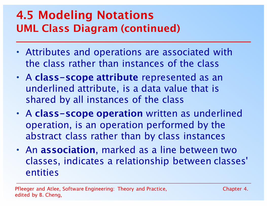
• Attributes and operations are associated with the class rather than instances of the class
• A class-scope attribute represented as an underlined attribute, is a data value that is shared by all instances of the class
• A class-scope operation written as underlined operation, is an operation performed by the abstract class rather than by class instances
• An association, marked as a line between two classes, indicates a relationship between classes' entities

Pfleeger and Atlee, Software Engineering: Theory and Practice, edited by B. Cheng,
Chapter 4.
4.5 Modeling NotationsUML Class Diagram (continued)
• Aggregate association is an association that represents interaction, or events that involve objects in the associated (marked with white diamond)– “has-a” relationship
• Composition association is a special type of aggregation, in which instances of the compound class are physically constructed from instances of component classes (marked with black diamond)

Pfleeger and Atlee, Software Engineering: Theory and Practice, edited by B. Cheng,
Chapter 4.
4.5 Modeling NotationsEvent Traces
• A graphical description of a sequence of events that are exchanged between real-world entities– Vertical line: the timeline of distinct entity, whose
name appear at the top of the line– Horizontal line: an event or interaction between the
two entities bounding the line– Time progresses from top to bottom
• Each graph depicts a single trace, representing one of several possible behaviors
• Traces have a semantic that is relatively precise, simple and easy to understand

Pfleeger and Atlee, Software Engineering: Theory and Practice, edited by B. Cheng,
Chapter 4.
4.5 Modeling NotationsEvent Traces (continued)
• Graphical representation of two traces for the turnstile problem– trace on the left represents typical behavior– trace on the right shows exceptional behavior

Pfleeger and Atlee, Software Engineering: Theory and Practice, edited by B. Cheng,
Chapter 4.
4.5 Modeling NotationsEvent Traces Example: Message Sequence Chart
• An enhanced event-trace notation, with facilities for creating and destroying entities, specifying actions and timers, and composing traces– Vertical line represents a participating entity– A message is depicted as an arrow from the
sending entity to the receiving entity– Actions are specified as labeled rectangles
positioned on an entity's execution line– Conditions are important states in an entity's
evolution, represented as labeled hexagon

Pfleeger and Atlee, Software Engineering: Theory and Practice, edited by B. Cheng,
Chapter 4.
4.5 Modeling NotationsMessage Sequence Chart (continued)
• Message sequence chart for library loan transaction

Pfleeger and Atlee, Software Engineering: Theory and Practice, edited by B. Cheng,
Chapter 4.
4.5 Modeling NotationsState Machines
• A graphical description of all dialog between the system and its environment– Node (state) represents a stable set of conditions
that exists between event occurrences– Edge (transition) represents a change in behavior
or condition due to the occurrence of an event• Useful both for specifying dynamic behavior
and for describing how behavior should change in response to the history of events that have already occurred

Pfleeger and Atlee, Software Engineering: Theory and Practice, edited by B. Cheng,
Chapter 4.
4.5 Modeling NotationsState Machines (continued)
• Finite state machine model of the turnstile problem

Pfleeger and Atlee, Software Engineering: Theory and Practice, edited by B. Cheng,
Chapter 4.
4.5 Modeling NotationsState Machines (continued)
• A path: starting from the machine's initial state and following transitions from state to state– A trace of observable events in the environment
• Deterministic state machine: for every state and event there is a unique response

Pfleeger and Atlee, Software Engineering: Theory and Practice, edited by B. Cheng,
Chapter 4.
4.5 Modeling NotationsState Machines Example: UML Statechart Diagrams
• A UML statechart diagram depicts the dynamic behavior of the objects in a UML class– UML class diagram has no information about how
the entities behave, how the behaviors change• A UML model is a collection of concurrently
executing statecharts• UML statechart diagram have a rich syntax,
including state hierarchy, concurrency, and intermachine coomunication

Pfleeger and Atlee, Software Engineering: Theory and Practice, edited by B. Cheng,
Chapter 4.
4.5 Modeling NotationsUML Statechart Diagrams (continued)
• State hierarchy is used to unclutter diagrams by collecting into superstate those states with common transitions
• A superstate can actually comprise multiple concurrent submachines, separated by dashed line– The submachines are said to operate concurrently

Pfleeger and Atlee, Software Engineering: Theory and Practice, edited by B. Cheng,
Chapter 4.
4.5 Modeling NotationsUML Statechart Diagrams (continued)
• The UML statechart diagram for the Publication class from the Library class model

Pfleeger and Atlee, Software Engineering: Theory and Practice, edited by B. Cheng,
Chapter 4.
4.5 Modeling NotationsUML Statechart Diagrams (continued)• An equivalent statechart for Publication class that does not
make use of state hierarchy or concurrency– comparatively messy and and repetitive

Pfleeger and Atlee, Software Engineering: Theory and Practice, edited by B. Cheng,
Chapter 4.
4.5 Modeling NotationsUML Statechart Diagrams (continued)• The UML statechart diagram for Loan association class illustrates how
states can be annotated with local variables, actions and activities

Pfleeger and Atlee, Software Engineering: Theory and Practice, edited by B. Cheng,
Chapter 4.
4.5 Modeling NotationsState Machines: Ways of Thinking about State
• Equivalence classes of possible future behavior
• Periods of time between consecutive event• Named control points in an object's evolution • Partition of an object's behavior

Pfleeger and Atlee, Software Engineering: Theory and Practice, edited by B. Cheng,
Chapter 4.
4.5 Modeling NotationsState Machines Example: Petri Nets
• A form or state-transition notation that is used to model concurrent activities and their interaction– Circles (places) represent activities or conditions– Bars represents transitions– Arcs connect a transition with its input places and
its ouput places– The places are populated with tokens, which act
as enabling conditions for the transitions– Each arc can be assigned a weight that specifies
how many tokens are removed from arc's input place, when the transition fires

Pfleeger and Atlee, Software Engineering: Theory and Practice, edited by B. Cheng,
Chapter 4.
4.5 Modeling NotationsPetri Nets (continued)
• Petri net of book loan

Pfleeger and Atlee, Software Engineering: Theory and Practice, edited by B. Cheng,
Chapter 4.
4.5 Modeling NotationsPetri Nets (continued)
• A high level Petri net specification for the library problem

Pfleeger and Atlee, Software Engineering: Theory and Practice, edited by B. Cheng,
Chapter 4.
4.5 Modeling NotationsData-Flow Diagrams
• ER diagram, event trace, state machines depict only lower-level behaviors
• A data-flow diagram (DFD) models functionality and the flow of data from one function to another– A bubble represents a process– An arrow represents data flow– A data store: a formal repository or database of
information– Rectangles represent actors: entities that provide
input data or receive the output result

Pfleeger and Atlee, Software Engineering: Theory and Practice, edited by B. Cheng,
Chapter 4.
4.5 Modeling NotationsData-Flow Diagrams (continued)
• A high-level data-flow diagram for the library problem

Pfleeger and Atlee, Software Engineering: Theory and Practice, edited by B. Cheng,
Chapter 4.
4.5 Modeling NotationsData-Flow Diagrams (continued)
• Advantage:– Provides an intuitive model of a proposed
system's high-level functionality and of the data dependencies among various processes
• Disadvantage:– Can be aggravatingly ambiguous to a software
developer who is less familiar with the problem being modeled

Pfleeger and Atlee, Software Engineering: Theory and Practice, edited by B. Cheng,
Chapter 4.
4.5 Modeling NotationsData-Flow Diagrams Example: Use Cases
• Components– A large box: system boundary– Stick figures outside the box: actors, both human
and systems– Each oval inside the box: a use case that represents
some major required functionality and its variant– A line between an actor and use case: the actor
participates in the use case• Use cases do not model all the tasks, instead
they are used to specify user views of essential system behavior

Pfleeger and Atlee, Software Engineering: Theory and Practice, edited by B. Cheng,
Chapter 4.
4.5 Modeling NotationsUse Cases (continued)
• Library use cases including borrowing a book, returning a borrowed book, and paying a library fine

Pfleeger and Atlee, Software Engineering: Theory and Practice, edited by B. Cheng,
Chapter 4.
4.5 Modeling NotationsFunctions and Relations
• Formal methods or approach: mathematically based specification and design techniques
• Formal methods model requirements or software behavior as a collection of mathematical functions or relations– Functions specify the state of the system's
execution, and output– A relation is used whenever an input value maps
more than one ouput value• Functional method is consistent and complete

Pfleeger and Atlee, Software Engineering: Theory and Practice, edited by B. Cheng,
Chapter 4.
4.5 Modeling NotationsFunctions and Relations (continued)
• Example: representing turnstile problem using two functions– One function to keep track of the state– One function to specify the turnstile output

Pfleeger and Atlee, Software Engineering: Theory and Practice, edited by B. Cheng,
Chapter 4.
4.5 Modeling NotationsFunctions and Relations Example: Decision Tables• It is a tabular representation of a functional
specification that maps events and conditions to appropriate responses or action
• The specification is formal because the inputs (events and conditions) and outputs (actions) may be expressed in natural language
• If there are n input conditions, there are 2n
possible combination of input conditions• Combinations map to the same set of results
can be combined into a single column

Pfleeger and Atlee, Software Engineering: Theory and Practice, edited by B. Cheng,
Chapter 4.
4.5 Modeling NotationsDecision Tables (continued)
• Decision table for library functions borrow,return, reserve, and unreserve
Possible Input events
Possible responses

Pfleeger and Atlee, Software Engineering: Theory and Practice, edited by B. Cheng,
Chapter 4.
4.5 Modeling NotationsLogic
• An operational notation is a notation used to describe a problem or a proposed software solution in terms of situational behavior– Model of case-based behavior– Examples: state machine, event traces, data-flow
diagram, functional method• A descriptive notation is a notation that
describes a problem or a proposed solution in terms of its properties or its variant– Example: logic

Pfleeger and Atlee, Software Engineering: Theory and Practice, edited by B. Cheng,
Chapter 4.
4.5 Modeling NotationsLogic (continued)
• A logic consists of a language for expressing properties and a set of inference rules for deriving new, consequent properties from the stated properties
• In logic, a property specification represents only those values of the property's variables for which the property's expression evaluates to true
• It is first-order logic, comprising typed variables, constants, functions, and predicates

Pfleeger and Atlee, Software Engineering: Theory and Practice, edited by B. Cheng,
Chapter 4.
4.5 Modeling NotationsLogic (continued)
• Consider the following variables of turnstile problem, with their initial value
• The first-order logic expressionsnum_coins > num_entries
(num_coins > num_entries ó (barrier = unlocked)(barrier = locked ) ó ¬may_enter

Pfleeger and Atlee, Software Engineering: Theory and Practice, edited by B. Cheng,
Chapter 4.
4.5 Modeling NotationsLogic (continued)
• Temporal logic introduces additional logical connectives for constraining how variables can change value over time
• The following connectives constrain future variable values, over a single execution– □f Ξ f is true now and throughout the rest of execution– ⋄f Ξ f is true now or at some point in the execution– ○f Ξ f is true in the next point in the execution– f W g = f is true until a point where g is true, but g may
never be true• Turnstile properties expressed in temporal logic□(insert_coin => ○ (may_enter W push))□(∀n(insert_coin ∧ num_coins=n) => ○(num_coins=n+1))

Pfleeger and Atlee, Software Engineering: Theory and Practice, edited by B. Cheng,
Chapter 4.
4.5 Modeling NotationsLogic Example: Object Constrain Language (OCL)
• A constraint language that is both mathematically precise and easy for non-mathematicians to read, write, and understand
• Designed for expressing constraints on object models, and expressing queries on object type

Pfleeger and Atlee, Software Engineering: Theory and Practice, edited by B. Cheng,
Chapter 4.
4.5 Modeling NotationsLibrary classes annotated with OCL properties

Pfleeger and Atlee, Software Engineering: Theory and Practice, edited by B. Cheng,
Chapter 4.
4.5 Modeling NotationsLogic Example: Z
• A formal requirements-specification language that – structures set-theoretic definitions of variables
into a complete abstract-data-type model of problem
– uses logic to express the pre- and post-conditions for each operation
• Method of abstractions are used to decompose a specification into manageable sized modules, called schemas

Pfleeger and Atlee, Software Engineering: Theory and Practice, edited by B. Cheng,
Chapter 4.
4.5 Modeling NotationsPartial Z specification for the library problem Opern is modified
or queried; (?)input/(!)output vars
Pre (input Item i? not already in Catalogue)and postconditions(‘) indicates after operation

Pfleeger and Atlee, Software Engineering: Theory and Practice, edited by B. Cheng,
Chapter 4.
4.5 Modeling NotationsAlgebraic Specifications
• To specify the behavior of operations by specifying interactions between pairs of operations rather than modeling individual operations
• It is hard to define a set of axioms that is complete and consistent and that reflects the desired behavior

Pfleeger and Atlee, Software Engineering: Theory and Practice, edited by B. Cheng,
Chapter 4.
4.5 Modeling NotationsAlgebraic Specifications Example: SDL Data
• Partial SDL data specification for the library problem

Pfleeger and Atlee, Software Engineering: Theory and Practice, edited by B. Cheng,
Chapter 4.
4.6 Requirements and Specification LanguagesUnified Modeling Language (UML)
• Combines multiple notation paradigms• Eight graphical modeling notations, and the
OCL constrain language, including– Use-case diagram (a high-level DFD)– Class diagram (an ER diagram)– Sequence diagram (an event trace)– Collaboration diagram (an event trace)– Statechart diagram (a state-machine model)– OCL properties (logic)

Pfleeger and Atlee, Software Engineering: Theory and Practice, edited by B. Cheng,
Chapter 4.
4.6 Requirements and Specification LanguagesSpecification and Description Language (SDL)• Standardized by the International Telecommunication
Union• Specifies the behavior of real-time, concurrent,
distributed processes that communicate with each other via unbounded message queues
• Comprises – SDL system diagram (a DFD)– SDL block diagram (a DFD)– SDL process diagram (a state-machine model)– SDL data type (algebraic specification)
• Often accompanied by a set of Message Sequence Chart (MSC)

Pfleeger and Atlee, Software Engineering: Theory and Practice, edited by B. Cheng,
Chapter 4.
4.6 Requirements and Specification LanguagesSDL System Diagram
• The top-level blocks of the specification and communication channels that connect the blocks
• Channels are directional and are labelled with the type of signals
• Message is asynchronous

Pfleeger and Atlee, Software Engineering: Theory and Practice, edited by B. Cheng,
Chapter 4.
4.6 Requirements and Specification LanguagesOther Features of Requirement Notations
• Some techniques include notations – for the degree of uncertainty or risk with each
requirement– for tracing requirements to other system
documents such as design or code, or to other systems, such as when requirements are reused
• Most specification techniques have been automated to some degree

Pfleeger and Atlee, Software Engineering: Theory and Practice, edited by B. Cheng,
Chapter 4.
4.7 Prototyping RequirementsBuilding a Prototype
• To elicit the details of proposed system• To solicit feedback from potential users
about– what aspects they would like to see improve– which features are not so useful– what functionality is missing
• Determine whether the customer's problem has a feasible solution
• Assist in exploring options for otimizing quality requirements

Pfleeger and Atlee, Software Engineering: Theory and Practice, edited by B. Cheng,
Chapter 4.
4.7 Prototyping RequirementsPrototyping Example
• Prototype for building a tool to track how much a user exercises each day
• Graphical respresentation of first prototype, in which the user must type the day, month and year

Pfleeger and Atlee, Software Engineering: Theory and Practice, edited by B. Cheng,
Chapter 4.
4.7 Prototyping RequirementsPrototyping Example (continued)
• Second prototype shows a more interesting and sophisticated interface involving a calendar– User uses a mouse to select the month and year– The system displays the chart for that month, and the
user selects the appropriate date in the chart

Pfleeger and Atlee, Software Engineering: Theory and Practice, edited by B. Cheng,
Chapter 4.
4.7 Prototyping RequirementsPrototyping Example (continued)
• Third prototype shows that instead of calendar, the user is presented with three slide bars– User uses the mouse to slide each bar left or right– The box at the bottom of the screen changes to show the
selected day, month, and year

Pfleeger and Atlee, Software Engineering: Theory and Practice, edited by B. Cheng,
Chapter 4.
4.7 Prototyping RequirementsApproaches to Prototyping
• Throwaway approach– Developed to learn more about a problem or a
proposed solution, and that is never intended to be part of the delivered software
– Allow us to write “quick-and-dirty”• Evolutionary approach
– Developed not only to help us answer questions but also to be incorporated into the final product
– Prototype has to eventually exhibit the quality requirements of the final product, and these qualities cannot be retrofitted
• Both techniques are sometimes called rapid prototyping

Pfleeger and Atlee, Software Engineering: Theory and Practice, edited by B. Cheng,
Chapter 4.
4.7 Prototyping RequirementsPrototyping vs. Modeling
• Prototyping– Good for answering questions about the user
interfaces • Modeling
– Quickly answer questions about constraints on the order in which events should occur, or about the synchronization of activities

Pfleeger and Atlee, Software Engineering: Theory and Practice, edited by B. Cheng,
Chapter 4.
4.8 Requirements DocumentationRequirement Definition: Steps Documenting Process
• Outline the general purpose and scope of the system, including relevant benefits, objectives, and goals
• Describe the background and the rationale behind proposal for new system
• Describe the essential characteristics of an acceptable solution
• Describe the environment in which the system will operate
• Outline a description of the proposal, if the customer has a proposal for solving the problem
• List any assumptions we make about how the environment behaves

Pfleeger and Atlee, Software Engineering: Theory and Practice, edited by B. Cheng,
Chapter 4.
4.8 Requirements DocumentationRequirements Specification: Steps Documenting Process
• Describe all inputs and outputs in detail, including– the sources of inputs– the destinations of ouputs, – the value ranges – data format of inputs and output data– data protocols– window formats and organizations– timing constraint
• Restate the required functionality in terms of the interfaces' inputs and outputs
• Devise fit criteria for each of the customer's quality requirements

Pfleeger and Atlee, Software Engineering: Theory and Practice, edited by B. Cheng,
Chapter 4.
4.8 Requirements DocumentationSidebar 4.6 Level of Specification
• Survey shows that one of the problems with requirement specifications was the uneven level of specification– Different writing sytles– Difference in experience– Different formats– Overspecifying requirements– Underspecifying requirements
• Recommendations to reduce unevenness– Write each clause so that it contains only one requirement– Avoid having one requirement refer to another requirement– Collect similar requirements together

Pfleeger and Atlee, Software Engineering: Theory and Practice, edited by B. Cheng,
Chapter 4.
4.8 Requirements DocumentationSidebar 4.7 Hidden Assumptions
• Two types of environmental behavior of interest– desired behavior to be realized by the proposed
system– existing behavior that is unchanged by the
proposed system• often called assumptions or domain knowledge
• Most requirements writers consider assumptions to be simply the conditions under which the system is guaranteed to operate correctly
Pfleeger and Atlee, Software Engineering: Theory and Practice, edited by B. Cheng,
Chapter 4.
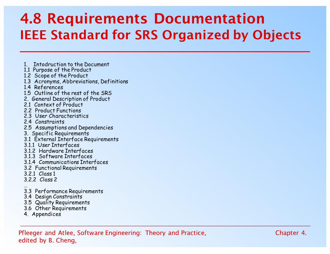
4.8 Requirements DocumentationIEEE Standard for SRS Organized by Objects
1. Intodruction to the Document1.1 Purpose of the Product1.2 Scope of the Product1.3 Acronyms, Abbreviations, Definitions1.4 References1.5 Outline of the rest of the SRS2. General Description of Product2.1 Context of Product2.2 Product Functions2.3 User Characteristics2.4 Constraints2.5 Assumptions and Dependencies3. Specific Requirements3.1 External Interface Requirements3.1.1 User Interfaces3.1.2 Hardware Interfaces3.1.3 Software Interfaces3.1.4 Communications Interfaces3.2 Functional Requirements3.2.1 Class 13.2.2 Class 2…3.3 Performance Requirements3.4 Design Constraints3.5 Quality Requirements3.6 Other Requirements4. Appendices

Pfleeger and Atlee, Software Engineering: Theory and Practice, edited by B. Cheng,
Chapter 4.
4.8 Requirements DocumentationProcess Management and Requirements Traceability
• Process management is a set of procedures that track– the requirements that define what the system should
do– the design modules that are generated from the
requirement– the program code that implements the design– the tests that verify the functionality of the system– the documents that describe the system
• It provides the threads that tie the system parts together

Pfleeger and Atlee, Software Engineering: Theory and Practice, edited by B. Cheng,
Chapter 4.
4.8 Requirements DocumentationDevelopment Activities
• Horizontal threads show the coordination between development activities

Pfleeger and Atlee, Software Engineering: Theory and Practice, edited by B. Cheng,
Chapter 4.
4.9 Validation and Verification
• In requirements validation, we check that our requirements definition accurately reflects the customer's needs
• In verification, we check that one document or artifact conforms to another
• Verification ensures that we build the system right, whereas validation ensures that we build the right system
Pfleeger and Atlee, Software Engineering: Theory and Practice, edited by B. Cheng,
Chapter 4.
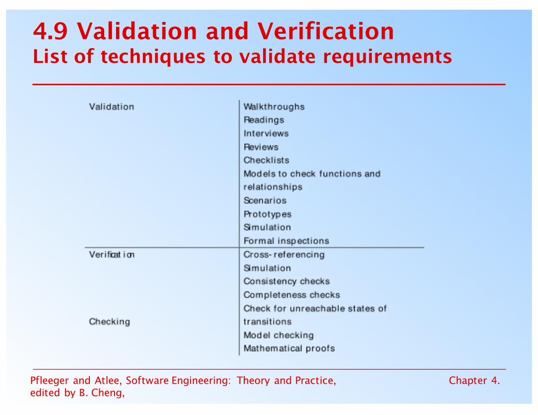
4.9 Validation and VerificationList of techniques to validate requirements
Pfleeger and Atlee, Software Engineering: Theory and Practice, edited by B. Cheng,
Chapter 4.
4.9 Validation and VerificationRequirements Review
• Review the stated goals and objectives of the system• Compare the requirements with the goals and
objectives• Review the environment in which the system is to
operate• Review the information flow and proposed functions• Assess and document the risk, discuss and compare
alternatives• Testing the system: how the requirements will be
revalidated as the requirements grow and change

Pfleeger and Atlee, Software Engineering: Theory and Practice, edited by B. Cheng,
Chapter 4.
4.9 Validation and VerificationSidebar 4.8 Number of Requirements Faults
• Jone and Thayes's studies show that– 35% of the faults to design activities for project of 30,000-35,000
delivered source instructions– 10% of the faults to requirements activities and 55% of the faults to
design activities for projects of 40,000-80,000 delivered source instructions
– 8% to 10% of the faults to requirements activities and 40% to 55% of the faults to design activities for project of 65,000-85,000 delivered source instructions
• Basili and Perricone report – 48% of the faults observed in a medium-scale software project
were attribute to “incorrect or misinterpreted functional specification or requirements”
• Beizer attributes 8.12% of the faults in his samples to problems in functional requirements

Pfleeger and Atlee, Software Engineering: Theory and Practice, edited by B. Cheng,
Chapter 4.
4.9 Validation and VerificationVerification
• Check that the requirements-specification document corresponds to the requirements-definition
• Make sure that if we implement a system that meets the specification, then the system will satisfy the customer's requirements
• Ensure that each requirement in the definition document is traceable to the specification

Pfleeger and Atlee, Software Engineering: Theory and Practice, edited by B. Cheng,
Chapter 4.
4.9 Validation and VerificationSidebar 4.9 Computer-Aided Verification
• Model checking is an exhaustive search for a specification's execution space, to determine whether some temporal-logic property holds of the execution– Atlee (1996) used the SMV model checker to verify five
properties of an SCR specification of the A-7 naval aircraft• A theorem prover uses a collection of built-in
theories, inference rules, and decision procedures for determining whether a set of asserted facts logically entails some unasserted fact– Dutertre and Stavridou (1997) used theorem prover PVS to
verify some of the functional and safety requirements of an avionic system

Pfleeger and Atlee, Software Engineering: Theory and Practice, edited by B. Cheng,
Chapter 4.
4.10 Measuring Requirements
• Measurements focus on three areas– product– process– resources
• Number of requirements can give us a sense of the size of the developed system
• Number of changes to requirements– Many changes indicate some instability or uncertainty
in our understanding of the system• Requirement-size and change measurements
should be recorded by requirements type

Pfleeger and Atlee, Software Engineering: Theory and Practice, edited by B. Cheng,
Chapter 4.
4.10 Measuring RequirementsRating Scheme on Scale from 1 to 5
1. You understand this requirement completely, have designed systems from similar requirements, and have no trouble developing a design from this requirement
2. Some elements of this requirement are new, but they are not radically different from requirements that have been successfully designed in the past
3. Some elements of this requirement are very different from requirements in the past, but you understand the requirement and can develop a good design from it
4. You cannot understand some parts of this requirement, and are not sure that you can develop a good design
5. You do not understand this requirement at all, and can not develop a design

Pfleeger and Atlee, Software Engineering: Theory and Practice, edited by B. Cheng,
Chapter 4.
4.10 Measuring RequirementsTesters/Designers Profiles
• Figure (a) shows profiles with mostly 1s and 2s – The requirements are in good shape
• Figure (b) shows profiles with mostly 4s and 5s– The requirements should be revised

Pfleeger and Atlee, Software Engineering: Theory and Practice, edited by B. Cheng,
Chapter 4.
4.11 Choosing a Specification TechniqueCriteria for Evaluating Specification Methods• Applicability• Implementability• Testability/Simulation• Checkability• Maintainability• Modularity• Level of abstraction• Soundness
• Veriability• Run time safety• Tools maturity• Looseness• Learning curve• Technique maturity• Data modeling• Discipline

Pfleeger and Atlee, Software Engineering: Theory and Practice, edited by B. Cheng,
Chapter 4.
4.11 Choosing a Specification TechniqueSteps• Determine which of the criteria are especially
important• Evaluate each of the candidate techniques
with respect to the criteria• Choose a specification technique that best
supports the criteria that are most important to the problem
Pfleeger and Atlee, Software Engineering: Theory and Practice, edited by B. Cheng,
Chapter 4.
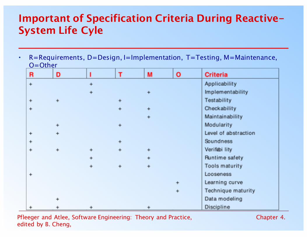
Important of Specification Criteria During Reactive-System Life Cyle
• R=Requirements, D=Design, I=Implementation, T=Testing, M=Maintenance, O=Other

Pfleeger and Atlee, Software Engineering: Theory and Practice, edited by B. Cheng,
Chapter 4.
4.14 What This Chapter Means for You
• It is essential that the requirements definition and specification documents describe the problem, leaving solution selection to designer
• There are variety of sources and means for eliciting requirements
• There are many different types of definition and specification techniques
• The specification techniques also differ in terms of their tool support, maturity, understandability, ease of use, and mathematical formality
• Requirements questions can be answered using models or prototypes
• Requirements must be validated to ensure that they accurately reflect the customer's expectations


![[E. Atlee Jackson] Equilibrium Statistical Mechani(BookFi.org)](https://img.pdfslide.net/doc/110x75/563dba71550346aa9aa5a9bb/e-atlee-jackson-equilibrium-statistical-mechanibookfiorg.jpg)