Embed Size (px)
Citation preview

784028 1/2013
OWNER’S MANUAL42SC/46SC

Table Of Contents1 INTRODUCTION
Regal Owner’s Manual 1-4
Owner’s Information Packet 1-4
General Information 1-5
Regal Marine Warranty 1-12 2 SAFETY ON BOARD
Safety Labels 2-1
General Boating Safety 2-2
Required Safety Equipment 2-4
Fire Extinguishers 2-6
Visual Distress Signals 2-7
Sound Protecting Devices 2-10
Radio Communications 2-10
Navigation Lights 2-10 Marine Sanitation Devices 2-10 Pollution Regulations 2-12
EBIRB 2-12
Garbage Discharge 2-13
Life Rafts 2-14
U.S.C.G Minimum Equipment Requirements 2-14
Exhaust & Carbon Dioxide 2-15 Boating & Alcohol 2-19 Boating Accidents 2-20 Water Sports 2-22 Weather & Water Conditions 2-23
3 RULES OF THE ROAD
Navigation Rules Defi ned 3-1
Navigation Rules 3-1

Table Of Contents4 SYSTEMS
Fuel 4-2
Electrical 4-12
Generator 4-51
Air Conditioning 4-56
Fresh Water/Waste 4-60
Trim Tabs 4-76
Sunroof 4-78
Windlass 4-79
Entertainment 4-84
Electronics 4-94
Propulsion 4-15
5 ENGINE/CONTROLS
Ventilation 5-3
Switches 5-4
Instrumentation 5-7
Remote Controls 5-11
6 VESSEL OPERATION
Getting Underway 6-1
Starting & Stopping 6-4
Fenders 6-5
Dock Line Basics 6-6
Knots 6-8
Docking 6-8
Anchoring 6-9
Towing/Admiralty Law 6-11
Emergencies 6-11
Environmental Awareness 6-14

Table Of Contents7 AUXILIARY EQUIPMENT OPERATION
INTERIOR EQUIPMENT
CO Detector 7-3
Door-Cabin Entry 7-4
Gray Water 7-4
Hatches 7-5
Monitor- Water/Waste 7-9
Portlights 7-10
Range 7-11
Refrigerator 7-12
Salon Table 7-15
Seat-Helm 7-16
Television 7-17
Vacuum Cleaner 7-18
Washer/Dryer 7-20

Table Of ContentsEXTERIOR EQUIPMENT
Antennae 7-27 Bilge Pump/Float 7-28 Bottom Paint 7-29
Camera Monitors 7-30
Compass 7-31
Cool Cockpit Air Conditioner 7-32
Door-Transom 7-33
Electronics 7-34
Fire Extinguisher- Automatic 7-35
Generator 7-37
Hardtop 7-38
Hatch-Engine 7-39
Heater-Hot Water 7-40
High Water Alarm 7-41
Installation/Removal Aft Filler Cushions 7-42
Markers For Slings 7-45
Oil Changer 7-46
Overboard Discharge Pump 7-50
Pump-Fresh Water 7-51
Satellite Radio 7-52
Shower-Transom 7-53
Sirius Marine Weather 7-54
Spotlight 7-56
Sunpads 7-57
Swim Ladder 7-58
Swim Platform 7-59
Underwater Lighting 7-61

Table Of Contents8 COSMETIC CARE & MAINTENANCE
Cosmetic Care 8-1
Maintenance 8-23
9 TROUBLESHOOTING
Diagnostic Charts 9-1
10 STORAGE & WINTERIZATION
Checklists 10-2
11 GLOSSARY & INDEX 11-1
12 TECHNICAL
Technical Information 12-1
Technical Drawings 12-9

1
Introduction
Boating is becoming more popular each and every year. There are numerous types of recreational vessels on our waterways today involved in an every growing number of activities. Therefore, as a Regal yacht owner it is of the highest priority to learn about general boating practices before operating your yacht. Your Regal yacht dealer will answer many questions and provide valuable “hands on” information during the completion of the new boat delivery process. In addition, your dealer has received special factory training on the product line and his services should be employed to solve any technical problems and periodic maintenance beyond the scope of this manual. Also, your Regal yacht dealer carries a line of factory approved parts and accessories.
Your Regal yacht dealer can provide information regarding national training organizations such as the U.S. Power Squadron and United States Coast Guard Auxiliary. Along with other organizations and literature, they can help build your “boating savvy” by developing the necessary skills and awareness to be a safe and confi dent skipper. Also, your local library can assist in providing recommended boating literature such as Chapman Piloting Seamanship & Boat Handling by Elbert S. Maloney.Also, boating information is available on the internet.Remember, waterway conditions can change in a heartbeat. Knowing how to react quickly comes from experience and knowledge which can be gained through boating education. Welcome aboard!

2
Chapter 1
I know I speak for everyone at Regal when I welcome you to the ever-growing family of Regal yacht owners. You’ve chosen a yacht that is recognized worldwide for its stan-dard of excellence. Each step in construction has been carefully scrutinized to assure safety, performance, reliability and comfort for both your passengers and yourself.
Your yacht is certified by the National Marine Manufacturers Association. It also complies with the applicable standards set by the United States Coast Guard , American Boat and Yacht Council and the International Marine Certification Institute. Your Regal yacht was built with the same attention to detail and quality of construction that we would expect in a yacht we would purchase ourselves. Whether you’re a veteran boater or a newcomer, we strongly urge you to read this yacht owner’s manual thoroughly. Familiarize yourself with the various components of your yacht, and heed the safety precautions noted herein.
If you have questions that are not covered in this manual, please consult your autho-rized Regal yacht dealer for assistance, phone the Regal factory at 407-851-4360 or E-mail us at www.regalboats.com.
Thank you, and welcome to the “World of Regal !”
Duane KuckPresident & CEO
WELCOME TO REGAL

3
IntroductionREGAL MARINE INDUSTRIES, INC.
MISSION STATEMENT
With God’s help
and a steadfast commitment to integrity,
we will develop a team of exceptional people and relationships to provide exceptional customer satisfaction.

4
Chapter 1
Your Regal yacht owner’s manual has been compiled with information covering both earlier and later models to assist you in operating your craft with safety and pleasure. This manual targets specifi c details of Regal related systems and components along with their location, operation and maintenance that normally is not found in the vendor information. In addition, vendor related equipment information is located within the yacht documentation package.
The Regal yacht owner’s manual is not to be thought of as a complete shop technical document. In addition to the system chapters, there is troubleshooting information devoted to select current standard and optional equipment. Beyond the owner’s manual your Regal yacht dealer has received special factory training and his services should be employed to solve more technical problems. Call 407-851-4360 or go to the internet at www.RegalBoats.com to fi nd the closest Regal yacht dealership. In keeping with its commitment to improvement Regal Marine Industries, Inc. is continually upgrading the product line. Regal notes that all dimensions, specifications, models, standard and optional equipment is subject to change without notice at any time.
An owner’s information packet is located on the vessel. Read and become familiar with the materials. This packet contains valuable literature on your propulsion package, standard and optional equipment, systems, various care and cleaning instructions along with component warranty information. Store the information packet in a clean, dry location.
OWNER’S PACKETREGAL OWNER’S MANUAL
PREVENT INJURY, DEATH, ORPROPERTY DAMAGE!
READ AND UNDERSTAND THE PROPULSION OWNER’S MANUAL
BEFORE ATTEMPTING TO OPERATE THE VESSEL.
WARNING!

5
Introduction
NMMA YACHT CERTIFICATION PLATE
At the helm (dash) area you will notice a metal plate which recognizes that your yacht was built to design compliance in effect on the date the certifi cation was verifi ed. The plate also states that your vessel complies with U. S. Coast Guard safety system standards in effect on the date of certifi cation.
VESSEL INFORMATION SHEET
It is recommended that you fi ll out the information on the following page. It will supply vital statistics on your vessel. Make a copy of the data for safe keeping at home.
Formulate the fl oat plan on the following page before departing. Leave it with a responsible person who will notify the United States Coast Guard or local law enforcement authorities if you do not return as planned. If you change your plans be sure to notify this person. Make copies of the fl oat plan and use one each time you go boating. This will help people know where to fi nd you should you not return on schedule. Do not fi le the fl oat plan with the United States Coast Guard.
VESSEL FLOAT PLAN
The United States Coast Guard has established a universal system of numerically recognizing vessels by using a hull identifi cation number or “HIN.” This number identifi es your Regal yachts’ model, hull number, month and year of manufacture. The HIN is normally found on your yacht’s transom, on the starboard side, just below the rub rail on the transom vertical surface. The HIN is stamped on a plate and reinforced with a special adhesive. The HIN consists of 12 alpha or numeric characters.It is recommended that you locate and write down the HIN for future reference. It can be especially useful when ordering parts from your Regal yacht dealer. A second HIN number is found in a hidden location. This second HIN is useful to authorities if the vessel is stolen and/or the original transom HIN is modifi ed or eliminated.
GENERAL INFORMATION
HULL IDENTIFICATION NUMBER (HIN)
HULL IDENTIFICATION NUMBER
RUB RAIL
TRANSOM
HIN

6
Chapter 1
YACHT INFORMATION Owner: ______________________________________________________________________
Address: ______________________________________________________________________
City & State: ___________________________________________________________________
Home Phone: ____________________ Business Phone: ________________________________
In Case Of Emergency Notify: ____________________________________________________
Address ______________________________________________________________________
City__________________________________State ___________________________________
Phone _______________________________________________________________________
Insurance Agent’s Name: _________________________________________________________
Policy#: _____________________________________________________________________USCG Phone: ___________________ Local Police:____________________________________
Marina Phone: _________________ Slip (Dock#): ____________________________________
Hull Serial #: RGM __ __ __ __ __ __ __ __ __Key #:__________ Port Engine:_____________ Stbd Engine: ___________________________Key #:__________ Cabin Door: __________________________________________________
Selling Dealer: _________________________________________________________________
Address: _____________________________________________________________________
City & State: __________________________________________________________________
Phone: ______________________ Fax: ____________________________________________
Servicing Dealer: _______________________________________________________________
Address:______________________________________________________________________
City & State:___________________________________________________________________
Phone:______________________ Fax:______________________________________________

7
Introduction
Fill out this form before departure. Leave it with a responsible person who will notify the Coast Guard or police if you don’t return as planned. If you change your plans be sure to notify this person. Make copies of the fl oat plan and use one each time you go on a trip. This will help people know where to fi nd you should you not return on schedule. Do not fi le this plan with the Coast Guard.
Persons Aboard:Name Age Address Phone __________________________________________________________________________________ __________________________________________________________________________________ __________________________________________________________________________________ __________________________________________________________________________________ __________________________________________________________________________________ __________________________________________________________________________________
Owner: _________________________________ Safety Equipment Aboard: __________________Address: ________________________________ Life Jackets City & State: _____________________________ First Aid Kit Telephone#: _____________________________ Flares _______________________________________ Flash Light _______________________________________ VHF Radio Person Filing Report: ______________________ Cell Phone __#____________________Name __________________________________ Computer __Desk Top ____Lap Top___Telephone ______________________________ E-mail address_____________________ _______________________________________ Food_____Water____ _______________________________________ Make Of Yacht: __________________________ State Registration#________________________Length______Boat Name ___________________ Destination:Color_______ Trim____ Hp ________________ Leave From __________________________Inboard ______ Stern Drive _________________ Time Left ____________________________Hull I.D.# _______________________________ Going To ____________________________ Documented Vessel # ______________________ Fuel Capacity ____________________________ _______________________________________ Est. Day Of Arrival _______________________Other Information ________________________ ____________________________________ _______________________________________ Est. Time Of Arrival ______________________ _______________________________________ If Not Back By____o’clock Call Authorities _______________________________________ _______________________________________
YACHT FLOAT PLAN
____See Other Side For Additional Persons

8
Chapter 1
Obtain a current weather update.
Periodically hoist the yacht & inspect the hull bottom and propellers for damage. Marine growth such as barnacles will affect performance and fuel effi ciency. Check sacrifi cial anodes located on the IPS propulsion unit, transom and engine. Replace anode if less than 2/3 remaining.
Check the electrical system and all safety related equipment. Carry extra fuses. Ensure they are of the proper capacity and type. If your yacht has been in the water, run the bilge pump until the fl ow of water stops.
If your yacht has been out of the water, check to see that all bilge water has drained. Check that all required safety equipment is on board and in good working condition. Examples include personal fl otation devices (PFD’s), horn, bell, hand held fi re extinguishers, and visual distress signals.
Check fuel level. Fuel tanks should be fi lled to slightly less than capacity. Allow for fuel expansion. Remember the “one third rule”.
Open engine compartment. Inspect for fuel odors and visible leaks in the fuel, oil, coolant, exhaust and power steering systems.
Check the diesel fuel fi lters for the presence of water .
Check fl uid levels of engines, drives and generator. Visually inspect engine for cracked hoses, worn or loose V-belt, and loose hardware.
YACHT CRUISE CHECKLIST

9
Introduction
RECOMMENDED ONBOARD EQUIPMENT
Allen Wrenches Fuel Filters-Engines & Generator Jack Knife Poly V- Belt (See Engine Manual)Phillips Screwdriver Coolant For Engine Freshwater System Extra Light BulbsRegular & Needle Nose Pliers Seawater FilterCombination Box & End Wrench Set Fuses Screwdriver Set (One With Various Tips) Propeller Set (See Dealer) Side Cutters Propeller HardwareRatchet & Socket Set Flashlight BatteriesElectrical Crimper,Cutter,Stripper Combo Engine Spare PartsHammer Generator Spare PartsVOA Electrical Tester Air Filters-Engine & GeneratorWater Pump Pliers Oil Filters-Engine, GeneratorVise Grip Pliers Drive Oil FiltersFloating Flashlight/Lantern Oil/Fuel Filter Wrench Tape Rule BASIC GEAR & SUPPLIES BASIC GEAR & SUPPLIES Tow Line Lubricating Oil, Liquid WrenchMooring Lines Duct & Electricians TapeDock Fenders Coolant (Engine Freshwater Side)Distress Signals Engine, Drive, Power Steering OilFirst Aid Kit Boat Soap (Not Dish Soap)Boat Hook Woody WaxCharts & Plotting Instruments/Back-up Use Vinyl Cleaner Emergency Food & Water Hydrogen Peroxide (AC Pans) EPIRB Life RaftBailer or Hand Pump Rust Stain Remover (Starbrite)Extra Hand Held Fire Extinguishers Corrosion Block Personal Floatation Devices Bilge Cleaner Clean Rags, Diapers (For Under Engine-Oil Leaks) Nylon Windbreaker SuitSunscreen (SPF 30+) Shop Vac (1 Gal. Cap. Wet-Dry)Bucket/Pans w/Lids-Draining/Storing Used Fluids SqueegeeMirror (For Inspection & Emergency Signaling) Binoculars Funnel
TOOLS SPARE PARTS

10
Chapter 1
Please note that your Regal yacht requires the proper registration by your authorized Regal yacht dealer. To initiate the vessel warranty your dealer must complete the owner’s registration form and systems checklist at the time of delivery. The owner must sign the paperwork to acknowledge that the dealer has reviewed the boat systems and warranty provisions with the owner. The owner should keep the original paperwork that features a temporary warranty registration. A warranty certifi cate will be sent approximately 6 weeks after receipt of the paperwork at Regal World Headquarters.
Your vessel has undergone rigid quality assurance inspections before leaving the factory. In addition, your dealer has been trained to perform fi nal pre-delivery checks and to service your Regal yacht.
Your dealer’s responsibilities include:
1. An orientation in the operation of your Regal yacht including matters relating to the safe operation of the vessel.
2. Completion and mailing of your boat registration warranty form to Regal.
3. Location of vendor warranties, registration materials, owner’s manual, operation, installation and maintenance instructions for auxiliary equipment supplied with or installed on your Regal boat.
Dealer’s ResponsibilityOwner’s Registration & Systems Checklist

11
IntroductionOwner’s Responsibility
You are entitled to all the benefi ts and services outlined in your Regal warranty. However, you have certain responsibilities to ensure warranty satisfaction.These are:
To read the warranty materials and understand them fully.
To examine the yacht in detail at the time of delivery.
Apply the following: boating rules and regulations, safety equipment, environmental regulations, accident reports and warranty regulations terms and conditions.
To read thoroughly all literature supplied with your yacht including this owner’s manual and to follow the recommendations in the literature.
To provide proper maintenance and periodic servicing of your yacht and equipment as set forth in the various manuals supplied.
Customer Service
Take the time to write down your yacht dealer’s phone number and E-mail address for future reference. Along with your Regal yacht dealer information is a listing below of other phone numbers and web addresses which may prove useful.
Regal Yacht Dealer:Phone: ______________________________________E-mail: ______________________________________
Regal Marine Customer Service:1-800-US REGAL (1-800-877-3425)[email protected]@regalboats.com
Volvo Penta Of America (24-Hour Hotline Support):[email protected]

12
Chapter 1REGAL MARINE INDUSTRIES, INC.LIMITED WARRANTY
Welcome to the Worldwide Family of Regal Owners! We are very pleased that you have chosen a Regal Powerboat!
This document is your Warranty Registration Certifi cate and Statement of Warranty. Please check the registration information section for accuracy. If this information is not correct or if you change your address at some future date, please notify us at the following address: Regal Marine Industries, Inc. Attention: Warranty Registrations, 2300 Jetport Drive, Orlando, Florida 32809; or E-mail at [email protected].
Please read the warranty carefully. It contains important information on Regal’s claims procedures and your rights and obligations under this warranty.
WHAT IS COVERED: This Limited Warranty applies only to Regal boats beginning with model year 2013.
LIFETIME LIMITED STRUCTURAL HULL WARRANTY: Regal Marine Industries, Inc. warrants to the original retail purchaser of this boat if purchased from an authorized Regal dealer that the selling dealer or Regal will repair or replace the fi berglass hull if it is found to be structurally defective in material or workmanship for as long as the original retail purchaser owns the boat. For purposes of this warranty, the hull is defi ned as the single fi berglass casting which rests on the water. This limited warranty is subject to all limitations and conditions explained below.
FIVE-YEAR TRANSFERABLE LIMITED STRUCTURAL HULL WARRANTY: In addition to the Lifetime Limited Structural Hull Warranty, Regal offers a Transferable Five-Year Limited Structural Hull Warranty. Under the Five-Year Transferable Limited Structural Hull Warranty, Regal will repair or replace the fi berglass hull if it is found to be structurally defective in material or workmanship within the fi rst (5) years after the date of delivery to the original retail purchaser. Any remaining term of this Five-Year Limited Hull Warranty may be transferred to a second owner if within 60 days of purchase, the new owner registers the transfer with Regal and pays the established warranty transfer fee. Contact Regal Customer Service at the above address for details.
FIVE-YEAR LIMITED HULL BLISTER WARRANTY: Regal warrants that the selling dealer or Regal will repair any underwater gelcoated surfaces of the hull against laminate blisters which occur as a result of defects in material or workmanship within (5) years of the date of delivery, provided that the original factory gelcoat surface has not been altered. Alternation would include but is not limited to damage repair; excessive sanding, scraping, sandblasting; or from improper surface prepa-ration for application of a marine barrier coating or bottom paint, any of which shall void this Five-Year Limited Hull Blister Warranty. Proper preparation must be applied to the hull bottom if the boat is to be moored in the water for periods in excess of sixty (60) days. Regal Marine shall repair or cause to be repaired any covered laminate blisters based on the following prorated schedule.
Less than two (2) years from delivery date - 100%, Two (2) to three (3) years from delivery date - 75%, Three (3) to four (4) years from delivery date - 50%, Four (4) to fi ve (5) years from delivery date - 25%.Reimbursement shall be limited to one repair, not to exceed one hundred ($100.00) dollars per foot of boat length prior to prorating. Regals prior authorization for the method and cost of repair, must be obtained before repairs are commenced. All costs to transport the boat for repairs are the responsibility of the owner.
LIMITED GENERAL WARRANTY: In addition to above hull warranties, Regal warrants to the original purchaser of this boat if purchased from an authorized Regal dealer that the dealer or Regal will repair or replace any parts found to be defective in materials or workmanship for a period of one (1) year from the date of delivery, subject to all exceptions, limitations and conditions contained herein.
LIMITED EXTERIOR FINISH WARRANTY: Regal warrants that the selling dealer or Regal will repair cosmetic defects in the exterior gelcoated fi nish including cracks or crazing reported to Regal within 90 days from the date of delivery to the original retail purchaser, subject to all limitations and conditions contained herein. All warranty work is to be performed at a Regal dealership or other location authorized by a Regal Customer Service Manager after it is established to Regal’s satisfaction that there is a defect in material or workmanship.
REGISTRATION INFORMATION:
CUSTOMER OBLIGATIONS: The following are conditions precedent to the availability of any benefi ts under these limited warranties:(a) The purchaser must sign and the dealer must submit to Regal the “NEW BOAT DELIVERY CHECKLIST” within ten (10) days of the date of delivery and such information must be on fi le at Regal.(b) The purchaser must fi rst notify the dealer from whom the boat was purchased of any claim under this warranty within the applicablewarranty period and within a reasonable period of time (not to exceed thirty (30) days) after the defect is or should have been discovered; and (2) if such continued use causes other or additional damage to the boat or component parts of the boat.

13
Introduction(c) Regal will not be responsible to repair any condition or replace any part, (1) if the use of the boat is continued after the defect is or should have been discovered; and (2) if such continued use causes other or additional damage to the boat or component parts of the boat.(d) Based on the dealer’s knowledge of Regal’s warranty policy and/or consultations with Regal, the dealer will accept the claim and arrange for appropriate repairs to be performed, or deny the claim if it is not within the warranty.(e) The dealer will contact the Regal boat owner regarding instructions for delivery of boat or part for warranty repair if it is covered by the limited warranty. ALL COSTS TO TRANSPORT THE BOAT FOR REPAIRS ARE THE RESPONSIBILITY OF THE OWNER; (f) If the Regal boat owner believes a claim has been denied in error or the dealer has performed the warranty work in anunsatisfactory manner, the owner must notify Regal’s Customer Service Department in writing at the address listed for further consideration. Regal will then review the claim and take appropriate follow-up action.
WARRANTY EXCEPTIONS: THIS LIMITED WARRANTY does not cover and the following are not warranted:(a) Engines, metal plating or fi nishes, windshield breakage, leakage, fading and deterioration of paints, canvas, vinyl, upholstery and fabrics;(b) Gelcoat surfaces including, but not limited to, cracking, crazing, discoloration or blistering except as noted above;(c) Accessories and items which were not part of the boat when shipped from the Regal factory, and/or any damage caused thereby;(d) Damage caused by misuse, accident, galvanic corrosion, negligence, lack of proper maintenance, or improper trailering;(e) Any boat used for racing, or used for rental or commercial purposes;(f) Any boat operated contrary to any instructions furnished by Regal, or operated in violation of any federal, state, Coast Guard or other gov-ernmental agency laws, rules, or regulations;(g) The limited warranty is void if alterations have been made to the boat;(h) Transportation of boat or parts to and/or from the REGAL factory or service location;(i) Travel time or haul outs, loss of time or inconvenience;(j) Any published or announced catalog performance characteristics of speed, fuel and oil consumption, and static or dynamic transportation in the water;(k) Any boat that has been repowered beyond Regal’s power recommendations;(1) Boats damaged by accident and boats damaged while being loaded onto, transported upon or unloaded from trailers, cradles, or other devices used to place boats in water, remove boats from water or store or transport boats on or over land;(m) Water damage to, dry rot to, condensation to, or absorption by interior surfaces, wood structures or polyurethane foam;interior wood including, but not limited to, bleeding and/or discoloration as a result of condensation or moisture or water continually contact-ing the plywood causing staining to upholstery, carpet or other interior surfaces;(n) Costs or charges derived from inconveniences or loss of use, commercial or monetary loss due to time loss, and any other special, inciden-tal or consequential damage of any kind or nature whatsoever.
NO WAVIER OF THESE ITEMS: The terms, conditions, limitations and disclaimers contained herein cannot be wavered except by the Customer Service Manager of Regal. Any such wavier must be in writing. Neither the dealer, nor the customer, nor any service, sales and/or warranty representative of Regal is authorized to waive and/or modify these conditions, limitations and/or disclaimers.
GENERAL PROVISIONS: ALL GENERAL, SPECIAL, INDIRECT, INCIDENTAL AND/OR CONSEQUENTIAL DAMAGES ARE EXCLUDED FROM THIS WARRANTY AND ARE TOTALLY DISCLAIMED BY REGAL. IT IS THE INTEREST OF THE PARTIES THAT THE OWNER’S SOLE AND EXCLUSIVE REMEDY IS THE REPAIR OR REPLACEMENT OF THE VESSEL OR ITS ALLEGEDLY DEFECTIVE COMPONENT PARTS AND THAT NO OTHER LEGAL OR EQUITABLE REMEDIES SHALL BE AVAILABLE TO SAID OWNER. SOME STATES DO NOT ALLOW THE EXCLUSION OF INCIDENTAL OR CONSEQUENTIAL DAMAGES SO THE FOREGOING MAY NOT APPLY TO YOU. THIS IS A LIMITED WARRANTY; REGAL MAKES NO WARRANTY, OTHER THAN CONTAINED HEREIN; TO THE EXTENT ALLOWED BY LAW ANY WARRANTIES OF MERCHANTABILITY OR FITNESS FOR A PARTICULAR PURPOSE ARISING IN STATE LAW ARE EXPRESSLY EXCLUDED TO THE EXTENT ALLOWED BY LAW. ANY IMPLIED WARRANTY OF MERCHANTABILITY IS LIMITED TO THE PERIOD OF THIS LIMITED WARRANTY. ALL OBLIGATIONS OF REGAL ARE SPECIFICALLY SET FORTH HEREIN. REGAL DOES NOT AUTHORIZE ANY PERSON OR DEALER TO AS-SUME ANY LIABILITY IN CONNECTION WITH REGAL BOATS. Some states do not allow limitations on how long an implied warranty lasts, so the above limitation may not apply to you. Regal’s obligation with respect to this warranty is limited to making repairs to or replacing the defective parts and no claim for breach of warranty shall be cause for cancellation or rescission of the contract or sale for any boat manufactured by REGAL MARINE INDUS-TRIES, INC.Regal will discharge its obligations under this warranty as rapidly as possible, but cannot guarantee any specifi c completion date due to the different nature of claims which may be made and services which may be required. Regal reserves the right to change or improve the design of its boats without obligation to modify any boat previously manufactured. This limited warranty gives you specifi c legal rights, and you may also have other rights which may vary from state to
state. Regal shall in no way be responsible for any repairs not PRE-AUTHORIZED by a Regal Customer Service Manager or repairs performed by a repair
shop not PRE- AUTHORIZED by a Regal Customer Service Manager.

14
Chapter 1
Note
The information found in this owner’s manual may change at any time. Designated items referred to may not be installed on your vessel. In keeping with its commitment to continued product improvement Re-gal Marine Industries, Inc. reserves the right to modify the vessel at any time without notice including changes in specifi cations, colors, fabrics, materials and equipment or to discontinue a model. Regal is not obligated to make similar changes or modifi cations to models sold prior to the date of such changes. All specifi cations are approximate including weights, fuel fi gures and speeds.Speeds are calculated at sea level with a temperature of 70 to 85 degrees. Increases in altitude and/or temperature will reduce horse-power and thereby reduce the speed of the vessel.All information is for reference only and should be used as a guideline. Consult local and state guidelines as they may differ in your area. Any decisions relating to safe operation of the vessel are the responsibil-ity of the operator.
1
Safety awareness can not be over emphasized. Safety on board needs to be the skippers number one priority. In this manual you will fi nd many safety precautions and symbols
to identify safety related items. Heed all safety precaution information. Remember, the skipper is responsible for the safety of his passengers and crew.
SAFETY LABELS
SAFETY PRECAUTION DEFINITION
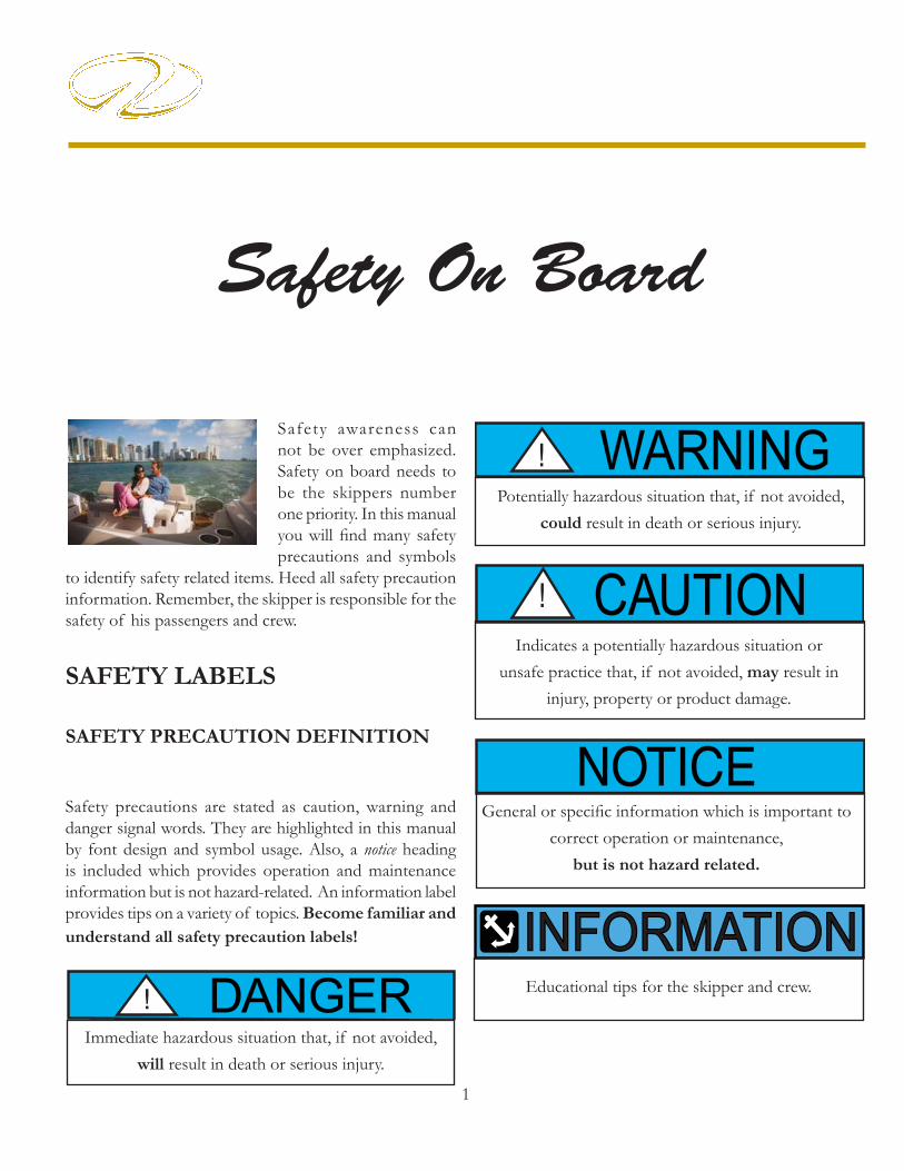
Safety precautions are stated as caution, warning and danger signal words. They are highlighted in this manual by font design and symbol usage. Also, a notice heading is included which provides operation and maintenance information but is not hazard-related. An information label provides tips on a variety of topics. Become familiar and understand all safety precaution labels!
Potentially hazardous situation that, if not avoided, could result in death or serious injury.
WARNING!
INFORMATIONINFORMATIONEducational tips for the skipper and crew. DANGER!
Immediate hazardous situation that, if not avoided, will result in death or serious injury.
CAUTION!Indicates a potentially hazardous situation or
unsafe practice that, if not avoided, may result in injury, property or product damage.
NOTICEGeneral or specifi c information which is important to
correct operation or maintenance, but is not hazard related.
Safety On Board

2
Chapter 2
We understand that you are eager to go boating. However, we strongly suggest that you thoroughly familiarize yourself and friends or members of your family with safe boating practices before setting out.Remember, that along with the freedom and exhilaration of boating comes the responsibility that you have for the safety of your passengers and other boaters who share the water with you.Boating regulations vary from state to state. Check with your local state and local authorities for the regulations pertaining to your area.
Check with local FM weather stations, U. S. Coast Guard, or on-line for the latest weather conditions. Remember getting caught in severe weather is hazardous. Check weather conditions periodically while you are boating. If you are forced to operate your boat in a storm condition, take common sense precautions; wear PFD’s, store gear, reduce speed and if possible head for safe refuge.
It is best to avoid operating your boat in foggy weather. When fog sets in, take bearings, log courses and speeds. You are required to emit a fi ve second blast from your horn or whistle once every minute. Also, have your passengers wear PFD’s and observe for oncoming vessels.
Operation in shallow water presents a number of hazards including sand bars and water levels infl uenced by tides. If the vessel strikes an underwater hazard, check for boat and engine damage. If the engine vibrates excessively after striking an underwater obstruction, it may indicate a damaged propeller. If you run aground, seek help by radio or fl ares.Make sure your boat and equipment are in top condition. Do this by frequently inspecting the hull, engine and propulsion components.
PRECAUTIONARY LABELS
Read and understand all safety labels affi xed to your Regal yacht or found in this manual and the vendor literature. Many of the safety labels are posted close to the helm, aft cockpit, cabin and swim platform. The location of the labels may vary. Review the helm safety labels with passengers before disembarking. Use common sense to analyze the result of an action on board your vessel. Always think safety fi rst!
DO NOT REMOVE OR COVER
ANY PRECAUTIONARY LABELS.
KEEP HARSH CHEMICALS
AWAY FROM LABELS.
IF A LABEL BECOMES ILLEGIBLE,
CONTACT YOUR REGAL DEALER
FOR ORDERING REPLACEMENTS.
NOTICE
GENERAL BOATING SAFETY

3
Safety On Board
You must provide a Coast Guard approved personal fl otation device (PFD) for every person on board. These PFD’s should be in good condition and easily accessible.
Insist that non-swimmers and children on board wear a PFD at all times. If you encounter rough weather conditions, make sure everyone on board is wearing a PFD, including yourself. Instruct your passengers in how to put on their PFDs and be sure they know their storage location on the boat. Remember, in an emergency, a PFD that cannot be quickly located and worn is useless.
Never allow anyone to sit anywhere on the boat not specifi cally designed as seating. While underway, ALWAYS insist passengers sit in a seat and set an example by doing this yourself.
Never drink and drive! As captain, you are responsible for the safety of your passengers. Alcohol and boat-ing can be a dangerous combina-tion. DO NOT mix them. Alcohol impairs the boat operators ability to make conscious decisions and react
to emergency situations quickly.
Use maximum caution when fueling. Never allow any smoke or fl ame nearby while you are fueling. ALWAYS check for fuel leaks and fumes when fueling is completed.
Be certain there is enough fuel aboard for your cruising needs. Include any reserve that might be needed should you change your plans due to weather or an emergency. Practice the “one-third rule: Use one-third of your fuel going out, one-third to
return and retain one- third as a reserve.
Always check the weather before departure. Be particularly cautious of forecasted electrical storms and high winds.
Always have up-to-date charts aboard as a back-up to your plotter and auto pilot option. Charts can be obtained at your closet marina, on-line store or by contacting one of three federal government agencies.
Always fi le a fl oat plan. Leave details of your trip with someone responsible who will be remaining on shore. Include expected return, plus name and phone number of a contact person in case of emergency.
Use care, courtesy and common sense when launching, docking or operating your boat.
Learn and obey the “Rules of the Road”. A weather resistant placard copy of the “Rules of the Road” is included in the on board Regal information packet. Additional information can be obtained from the U.S. Coast Guard Auxiliary or your local Power Squadron organization. In case of emergency know the international distress signals for your VHF radio. The spoken word “MAYDAY” is the international signal of distress and is for emergency use only. Under no circumstances should this word be used, unless there is danger at hand.
Never overload your boat! An overloaded boat, or one with uneven weight distribution can be diffi cult to steer.

4
Chapter 2
Posted speed limits, swimming areas, “no wake” zones and other restrictions should be red-fl agged. They are so noted for a reason. Sensible boat use, plus courtesy, equals enjoyable and safe boating.
It is your responsibility to stay abreast of all federal, state and local rules, as some laws or regulations may change or be different from state to state. Contact your local boating agencies for updated information.
We can not stress safety enough! Remember, there are no brakes on your boat, and the water current and wind velocity both affect your ability to respond. The operator must use caution at all times to maintain control of his vessel and especially to keep a safe distance from other boats and obstacles.
Always keep all safety gear in optimum condition. Pay special attention to attached tags and plates indicating expiration dates on equipment such as fi re extinguishers, and personal flotation devices. Encourage a periodic maintenance check on all safety equipment. Contact your Regal dealer or marine professional for more information. Again, remember that the captain is responsible for his crew, passengers and vessel.
PERSONAL FLOTATION DEVICES
All personal flotation devices (PFD’s) must be Coast Guard approved, in good working condition, and must be the correct size for the wearer. All PFD’s must be readily accessible. This means being able to wear them in a reasonable amount of time in case of an emergency (fi re, boat sinking, etc.). They should not be stored or locked in closed areas. Also, make sure that all coverings are removed such as plastic from any PFD’s. Throwable devices such as a ring buoy need to be available for immediate deployment. A PFD should be worn at all times when your boat is operating on the water. A PFD may save your life, but it must be worn to do so.As a minimum U. S. Coast Guard requirement all recreational boats must carry one type I, II, III, or V PFD (wearable) for each person aboard. See the explaination following for each type. For type V to be counted they must be used according to the label instructions. In addition, all boats over 16’ must carry one Type IV (throwable) PFD. Some states require that PFD’s be worn by children of specifi c ages at all times. Check with local and state boating agencies for particular requirements in your state before taking children on the water. Child life jackets are classifi ed by the child’s weight and should like all life jackets be sized before being purchased.Remember PFD’s will not necessarily keep you from drowning, even though they are designed to keep a person from sinking. When purchasing PFD’s make sure it safely fi ts the person wearing it. It is a good idea to test PFD’s in a lifeguarded shallow pool before venturing on the water.
REQUIRED SAFETY EQUIPMENT

5
Safety On Board
Refer to the USCG minimum equipment requirements at the end of this chapter. It is meant to be a guide only. Contact state and local agencies for additional equipment requirements. Remember as the captain of your vessel you are responsible for its safe operation.
TYPE II PDFBUOYANT VEST
TYPE II- Also known as near-shore buoyant vest, it is recommended for calm, inland water where rescue time will be minimal. It will turn some unconscious people face-up in the water but not as numerous as Type I. They use the same buoyancy
minimum poundages as the type I PFD’s.
TYPE III- Known as a fl otation aid it is good for calm, inland water or where there is a chance for quick rescue. It is designed so wearers can place themselves in a face-up position in the water. The wearer may have to tilt their head back to avoid face-down positions.
Type III offer the same buoyancy minimum poundages as the Type II. They are generally the most comfortable for continuous wear. Float coats, fi shing vests, and vests featuring designs for various sport activities are examples of Type III.
TYPE IV- Intended for calm, inland water with heavy vessel traffi c, where help is constantly present. It is designed to be thrown into the water for someone to grab on to and held until rescued. It is not designed to be worn. Type IV includes ring buoys, buoyant
cushions, and horseshoe buoys.
TYPE V- Also known as a special use device this is the least bulky of all PFD’s. It contains a small amount of inherent buoyancy, and an inflatable chamber. It is rated even to a Type I, II, or III PFD (as noted on the jacket label) when infl ated. Some Type V devices
provide signifi ciant hypothermia protection. Varieties include deck suits, work vests, board sailing vests and Hybrid PFD’s. Remember that this Type V type PFD may be carried instead of another PFD only if used according to the approval condition on the label.
Note: A water skier or wakeboarder is considered on board the vessel and a PFD is required for the purposes of compliance with the PFD carriage requirements. It is advisable and recommended for a skier or wakeboarder to wear a PFD designed to withstand the impact of hitting the water at a high speed. “Impact Class” marking on the label refers to PDF strength, not personal protection. Some state laws require a skier or wakeboarder to wear a PFD.
TYPE I- Also known as an off-shore jacket, it provides the most buoyancy. It is a PFD for all waters and is especially useful in rough waters where rescue may encompass additional time. It is designed to turn most unconscious users in the water to a true face-up
position. Type I PFD is available in adult & child sizes Buoyancy minimum poundages are 15.5 adult, 11 medium child, and 7 for small child and infants.

6
Chapter 2
MAINTAINING YOUR PFD’S
A PFD is only useful if it is well maintained. Always be aware of PDF age since it has a life expectancy like any other piece of equipment.
√ Check periodically for broken zippers, frayed webbing, water soaked kapok bags, missing straps, and sewing that has become undone.
√ Clean each PFD with mild soap and water only. Again, let dry suffi ciently before storing.
√ Keep PFD’s out of grease and oil since they can deteriorate the jacket inner and outer materials.
√ Check any kapok-bagged jackets by squeezing. If you hear air escaping the bag is defective and the PFD should be thrown away.
√ Grab the cover with the fi ngers. If the cover material rips, the PFD is rotted and should be thrown away.
√ If the kapok bag is hard the PFD should be discarded.
FIRE EXTINGUISHERS
GENERAL INFORMATION
Fire extinguishers are classifi ed by a letter and numeric symbol. The letter references the type of fi re the unit is designed to extinguish. For example, type B extinguishers commonly used on boats are designed to put out fl ammable liquids such as grease, oil and gasoline.The number indicates the general size of the extinguisher (minimum extinguishing agent weight). Coast Guard Approved extinguishers are identifi ed by the following marking on the label:
“Marine Type USCG Approved, Size... , Type... , 162.028/.../”, etc.
MINIMUM PORTABLE FIRE EXTINGUISHERS
REQUIRED
VESSEL NO FIXED WITH FIXED
LENGTH SYSTEM SYSTEM
LESS THAN 26’ 1 B-1 026’ TO LESS THAN 40’ 2 B-1 OR 1 B-II 1 B-140’ TO 65’ 3 B-1 OR 1 B-1 & 1 B-II 2 B-1 OR 1 B-2
FIRE EXTINGUISHER CONTENTS
CLASS FOAM C02 DRY CHEM HALON
IN GALS. IN LBS. IN LBS. IN LBS.
B-I 1.25 4 2 2.5
B-II 2.5 15 10 10
PFD’S FOR PETS
If you are a skipper who needs to have his pet dog or cat on board or dockside then a PFD is recommended. The PFD will aid you in fi nding the pet if it should fall overboard. The device must fi t the pet properly. Also, it may take a bit of training before the pet is comfortable wearing the PFD. Normally, dogs are easier to train wearing a life vest than a cat. Marine type retail stores will fi t a pet to a PFD by body weight.

7
Safety On Board
U. S. Coast Guard approved fi re extinguishers are required on all Regal yachts. Besides the minimum Coast Guard requirements always check state and local agencies for additional requirements and equipment.Coast Guard approved extinguishers are hand-portable, either B-I or B-II classification. U. S. Coast Guard approved hand-portable and semi-portable extinguishers contain a metal plate that shows the manufacturers name and extinguisher type, capacity and operating instructions. They have a special marine type mounting bracket which keeps the extinguisher solidly mounted until needed. The extinguisher needs to be mounted in a readily accessible location but one that will not be bumped by people while underway. All approved extinguishers shall have an indication gauge.
U.S.C.G APPROVED FIRE EXTINGUISHER TYPES & FEATURES
The carbon dioxide unit uses CO2 gas under high pressure, with a funnel discharge hose usually swivel mounted. This extinguisher leaves no residue and does not cause interior engine harm. To ensure workability, weigh the unit annually. A 10% maximum weight variance
is allowed. Another type of liquifi ed gas used today is FE-241.This gas is colorless and odorless, heavier than air and sinks to the lower bilge to extinguish fi res. Since the year 2000 ingredients have changed to a more environmental friendly formula (Chlorotetrafl uoroethane or FE-241). FE-241 is used in portable-hand units along with making up the majority of boat automatic fi re extinguishing systems. The canister needs to be weighed once a year. These clean agent units feature a dash mount indicator. Refer to the information regarding fi re prevention in this manual.
VISUAL DISTRESS SIGNALS
All vessels used on coastal waters, any of the Great Lakes, territorial seas, and those waters connected directly to them up to a point where a body of water is less than two miles wide, must be equipped with Coast Guard approved visual distress signals.Vessels owned in the United States operating on the high seas must be equipped with U.S.C.G. approved visual distress signals.
The dry chemical agent is widely used because of its convenience and low cost. The extinguisher canister is fi lled with a white dry chemical powder along with a pressurized gas. It is a good idea to shake this type periodically because they tend to “pack” on the canister bottom.
The foam type uses a chemical foaming agent plus water and is best when used for fi res involving fl ammable liquids- solvents, gasoline, oil, grease and various paints. It will work on fi res involving rubber, plastics, cloth, wood, and paper. It
leaves a messy residue. Do not use this extinguisher for electric fi res.

8
Chapter 2
.PYROTECHNIC DEVICES
Pyrotechnic visual distress signals must be Coast Guard approved, be ready for service and must be readily accessible. They all display a marking which is the service life, which must not have expired. A minimum of 3 devices are required for the day and 3 devices for night.Some devices meet both day and night requirements. Pyrotechnic devices should be stored in a cool, dry location. Most of these devices can be purchased in an highly visible (orange) watertight container. Types of Coast Guard approved pyrotechnic distress signals and associated devices are:
Pyrotechnic red fl ares, hand-held or aerial type.
Pyrotechnic orange smoke, hand-held or floating type.
Launchers for parachute fl ares or aerial red meteors.
All in all, each distress signal has certain advantages and disadvantages.There is no distress signal that is best under all situations. Pyrotechnics are recognized world-wide as superior distress signals. A downfall is they emit a very hot fl ame that can cause burns and or ignite fl ammable materials. Pistol launched and hand-held parachute fl ares operate consistant with fi rearms and therefore must be carefully handled. Check with local and state regulations since some of these device are considered fi rearms and are prohibited.It is best to carry red aerial fl ares which are visible from a greater distance. Also, the red parachute fl ares burn for longer periods and therefore are more likely to be seen by another vessel.
Non-pyrotechnic devices must all be in serviceable condition, readily accessible, and must be certifi ed by the manufacturer to comply with U.S.C.G standards. They include:
Orange distress fl ag.
Electric distress light.
The distress fl ag is for day use only. It must be 3 x 3 or larger with a black square and ball on an orange background. It can be spotted when attached to a boat hook, long fi shing rod, or paddle with the person waving the fl ag back and forth overhead.The electric distress light is for night use only fl ashing the international SOS distress signal (..._ _ _ ...).Under Inland Navigation Rules, a high intensity white light that fl ashes at regular intervals from 50-70 times per minute is considered a distress signal.Remember that regulations prohibit the display of visual distress signals on the water under any circumstances except when assistance is required to prevent immediate or potential danger to passengers on a vessel.
NON-PYROTECHNIC DEVICES

9
Safety On Board
INTERNATIONAL DISTRESS SIGNALS
BLACK SQUAREAND BALL ON
ORANGE BACKGROUND
CODE FLAGSNOVEMBER& CHARLIE
SQUARE FLAG& BALL
PERSONWAVINGHANDS
MORSECODE S.O.S.
“MAYDAY”BY
RADIO
ENSIGNUPSIDEDOWN
PARACHUTERED FLARE
RED METEORFLARES
SMOKE FOG HORN SOUNDED
CONTINUOSLY
GUN FIRED AT 1- MINUTEINTERVALS
POSITIONINDICATING
RADIO BEACONDYE MARKER(ANY COLOR)
HAND-HELDFLARE

10
Chapter 2
According to both Inland and International Rules, all boats must carry a way of producing an efficient sound signal. If your vessel is 12 meters (39’ 4”) or longer, a power whistle or power horn and bell must be carried. Bell mouth must be at least 7 7/8”
diameter. The sound signal made in all cases must be capable of a four or six second blast audible for one half mile. See the section discussing bridge and whistle signals for more information.
RADIO COMMUNICATIONS
VHF radios are used for distress and ship to shore and ship to ship communications today. Learn the specialized messages such as Mayday, Mayday, Mayday. It is only used when life or vessel is in imminent danger. Many of the more recent VHF’s feature DSC capability which offers the ability to place and receive digital calls directly with vessels and shore stations including USA and Canadian Coast Guards. Channel 70 is reserved exlusively for DSC calls. Refer to the VHF owner’s information since you need to establish a Mobile Maritime Safety Identity (MMSI) number before using the DSC feature. A MMSI number identifi es each DSC radio, like a telephone number. The FCC requires a ship station license for all vessels equipped with a marine VHF radio.
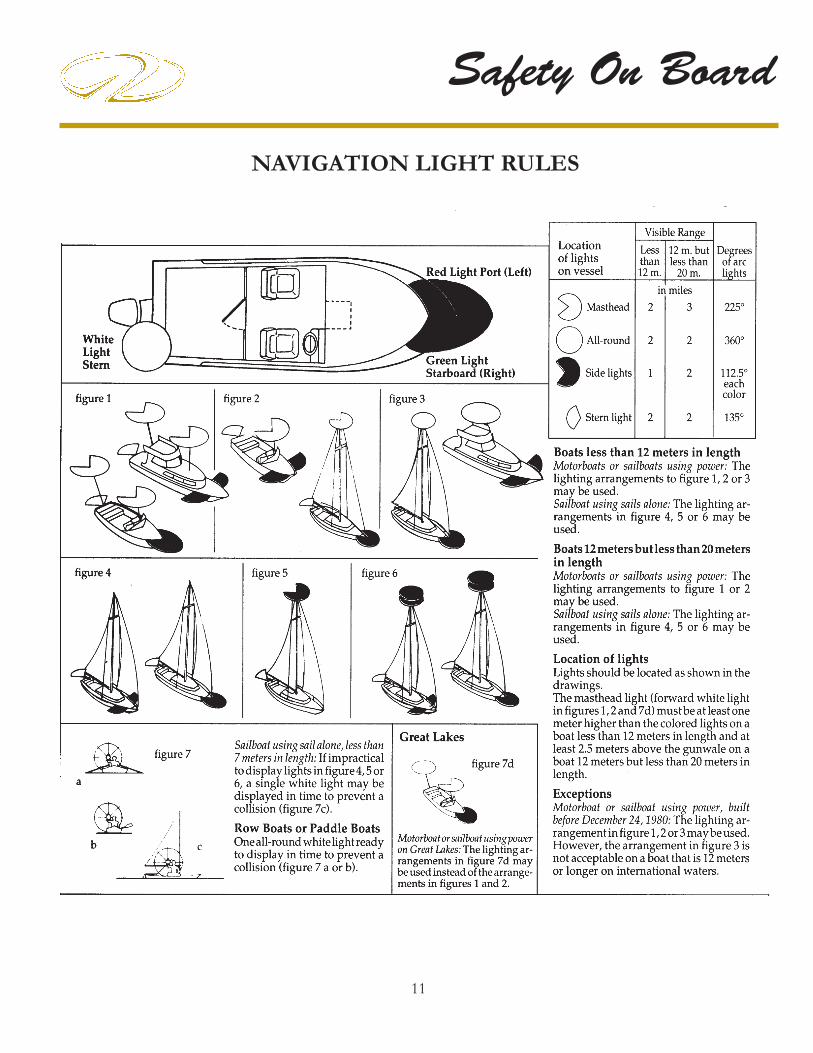
NAVIGATION LIGHTS
The U. S. Coast Guard requires recreational boats operating at night to display navigation lights between sunset and sunrise along with other periods of reduced visibility.Navigation lights help avoid collisions by improving the night visibility of vessels. Red and green directional lights, white stern lights, white masthead lights and white all-around lights must be displayed in specifi ed positions, depending on boat size, and mode of operation.
The confi guration of visible lights tells an operator the size, direction of travel and means of propulsion (sail, power, rowing or at anchor) of another vessel.This helps both operators determine who has the right of way. Larger boats are required to carry bigger, brighter lights that are visible over longer distances. See the light requirement chart for pleasure craft.
MARINE SANITATION DEVICESRecreational vessels under 65’ with installed toilet facilities must have an operable marine sanitation device (MSD) on board. Vessels 65’ and under may use Type I, II, or III MSD’s. All installed MSD’s must be U.S. Coast Guard certifi ed. The MSD’s are labeled to show conformity to the regulations.
SOUND PRODUCING DEVICES
NAVIGATION RULES
The navigation rules establish actions to be taken by vessels to avoid collision. They are divided into Inland/International. Operators of vessels 39.4’ or more shall have on board and maintain a copy of the Inland navigation rules.
11
Safety On Board
NAVIGATION LIGHT RULES

12
Chapter 2
POLLUTION REGULATIONS
DISCHARGE OF OIL PROHIBITEDTHE FEDERAL WATER POLLUTION CONTROL
ACT PROHIBITS THE DISCHARGE OF OIL OR OILY WASTE
INTO OR UPON THE NAVIGABLE WATERS AND CONTIGUOUS ZONE
OF THE UNITED STATES IF SUCH DISCHARGE CAUSES A FILM OR SHEEN UPON,
OR DISCOLORATION OF THE SURFACE OF THE WATER, OR CAUSES A SLUDGE OR EMULSION BENEATH THE SURFACE
OF THE WATER.VIOLATORS ARE SUBJECT TO
A PENALTY OF $5,000
NOTICE
MARPOL TREATY
The USCG now enforces the International Convention for the Prevention of Pollution from ships, referred to commonly as the MARPOL TREATY (marine pollution). This international treaty prohibits the overboard dumping of all oil, garbage, ship-generated plastic and chemicals. There is a placard on board your boat (typical example shown below) that explains the garbage and plastic dump-ing laws in detail.Immediately notify the USCG if your vessel discharges oil or hazardous substances in the water. Call toll free 1-800-424-8802. Report the following information: location, source, size, color, substances and time observed. No vessel may intentionally drain oil or oily waste from any source into the bilge of any vessel. A bucket or bailer is suitable as a portable means of discharging oily waste. The placard noted above is normally located in the engine or may be attached to the engine hatch.

13
Safety On Board
GARBAGE DISCHARGE
The act to prevent pollution from ships places limitations on the discharge of garbage from vessels. It is illegal to dump plastic trash anywhere in the ocean or navigable waters of the United States. Also, it is illegal to discharge garbage in the navigable waters of the United States, including the Great Lakes. The discharge of other types of garbage is allowed outside certain specifi ed distances from shore as determined by the nature of that garbage.United States vessels of 26 feet or longer must display in a prominent location, a durable placard at least 4” x 9” notifying crew and passengers of discharge restrictions. USA vessels of 26’ or longer equipped with a galley and berthing must have a written Management Plan describing the plan for collecting, processing, storing and discharging garbage, and designate the person charged with carrying out the plan.The placard noted below is usually found under the galley or the cockpit refreshment center.

14
Chapter 2
Inflatable life rafts are recommended for ocean going and vessels operating in a large body of water like the Great Lakes.
They provide a shelter for extended periods. If used, make sure it is large enough for all aboard and contains the proper emergency equipment pack. Also, periodically have the unit professionally serviced. Make sure the life raft is Coast Guard approved since it would require meeting a number of stringent material and performance standards.
LIFE RAFTS USCG MINIMUM EQUIPMENT REQUIREMENTS
Use the chart below as a guideline for assuring your vessel is outfi tted to meet USCG standards. Remember to check with local and state authorities for additional equipment requirements. Make sure your vessel certifi cate of numbers are on the boat, updated and displayed properly according to state requirements. Keep the paperwork on board in a watertight and safe environment. Make sure it is quickly accessible.On documented vessels keep both the original and current certifi cate on board stored in a safe, dry, and accessible location. Also, on documented vessels make sure the vessel name/hailing port are marked on the hull exterior with letters not less than 4” in height. In addition, the Offi cial Number must be permanently affi xed on a clearly visible interior structure part of the boat-block type Arabic numbers not less than 3” in height.

15
Safety On Board
EXHAUST & CARBONMONOXIDE
Carbon monoxide (CO) in exhaust can be hazardous.
especially from gasoline engines, gasoline generators,
grills, stoves, space heaters and on a much smaller
degree diesel engines.
CO is a natural by-product of the gasoline engine using an artifi cial spark . Diesels on the other hand detonate fuel using pressure and temperature. Looking at the two engines another way, gasoline engines use much more oxygen up in the combustion process which contributes to a much higher CO build-up. Although diesels do produce a small amount of CO the combustion process operates with much greater amounts of oxygen which the end result is a much lower CO level. In conclusion, even though your yacht may use diesel
propulsion ensure that you read the information and
follow all the recommendations regarding CO as if
it were gasoline powered.
Familiarize your crew, passengers and yourself
with the sources, symptoms and possible effects of
carbon monoxide poisoning. Remember that boats
in the same general vicinity can cause your vessel to
accumulate dangerous CO levels in the cabin and or
under the hardtop operating with the above conditions
and sources.
AVOID SERIOUS INJURY OR DEATH
FROM CO POISONING!
DO NOT OPERATE THE BOAT WITH PEOPLE
HOLDING ON TO THE SWIM PLATFORM
OR WITH PEOPLE IN THE WATER.
WARNING!
For safety sake avoid the following:
1. Do not park by other boats with their engine idling or generator cycling for an extended period of time .2. Do not disable the carbon monoxide alarms that come with your Regal boat. Test the units in accordance with the alarm manufacturers instructions.
3. Do not operate an engine for extended periods of time while in a confi ned area or where exhaust outlets face a sea wall or bulkhead.
4. Do not operate the engine for an extended period of time with the canvas in the upright and installed position.
5. Have the engine exhaust system inspected when the boat is in for service.
6. Persons sleeping can easily be overcome by carbon monoxide without realizing it. Do not sleep on board while an engine or generator is running close-by.
7. Do not operate your vessel for extended periods with the bow up in slow cruise conditions especially close behind a vessel being towed or one operating at slow speeds.
8. When underway open all hatches, windshield vents, and main cabin entry door to allow proper airfl ow from bow to stern.

16
Chapter 2
Blockage of exhaust outlets can cause carbon monoxide to accumulate in the cabin and cockpit area even when the hatches, windows, portholes and
doors are open. Sea walls and other confi ned spaces can cause CO levels to be dangerously elevated.
Exhaust from another vessel alongside your boat, while docked or anchored, can emit poisonous CO gas inside the cabin and cockpit areas of your boat.
The “station wagon effect” or backdrafting can cause CO gas to accumulate inside the cabin, cockpit/hardtop or bridge areas when the boat is under-way,
using protective weather coverings (canvas), high bow angle, improper or heavy loading, slow speeds, or at rest. This can occur when traveling behind another boat.
How does CO affect us?
In high concentrations, CO can be fatal in minutes. However, the effects of lower concentrations over a extended period of time can be just as lethal.Our blood uses hemoglobin to carry the oxygen we breathe to different body parts. Unfortunately, hemoglobin carries CO more readily than it does oxygen. The result is when we breathe in CO it replaces oxygen in our blood and we begin to suffocate. Also, when we are removed from the CO source it remains in our blood for hours causing long term effects. People have been known to become sick and even lose consciousness hours after exposure.
Carbon monoxide accumulation requires immediate attention! Thoroughly ventilate cabin and cockpit areas. Determine the probable source of the carbon monoxide and correct the condition immediately. Anyone with symptons of CO poisoning should be placed in a fresh air environment and medical attention found immediately. Regal has installed CO detectors on your boat. Have these detectors professionally calibrated at regular intervals according to the equipment manufacturer’s recommendations.
A Few Notes About Diesel/CO Poisoning
The diesel engine under normal combustion produces much smaller amounts of CO. Therefore, it is far less likely to be fatal to a healthy person. Other factors including weather, temperature and engine condition can greatly affect the unsafe build-up of CO. The best approach is to respect and treat the engine, generator and other vessel components the same way you would a gasoline propulsion system giving particular attention to the sources and possible effects of CO poisoning! Diesel exhaust in the combustion process produces various components and the captain must be aware that the build-up of these select components over a period of time can cause CO or seasickness like symptoms. These include carbon dioxide, carbon monoxide (CO), nitrogen dioxide, nitric oxide, sulfur dioxide and others.A healthy person breathing in sulfur dioxide over a period of time through a diesel engine or generator exhaust can develop nausea. This condition is not life threatening but the person may exhibit CO poisoning or seasickness symptoms. Just never rule out that it could be CO poisoning! Immediately fi nd the source of the problem and move the individual to a fresh air environment!

17
Safety On Board
Symptoms of excessive exposure to carbon monoxide (CO) are:
• Dizziness • Watering, itchy eyes • Drowsiness • Flushed appearance • Nausea • Inattentiveness• Headache • Incoherence• Ringing in the ears • Fatigue or vomiting• Throbbing temples • Convulsions
To help prevent carbon monoxide accumulation, ventilate your cabin and cockpit while underway. Open a forward hatch, porthole or window to allow air to travel through the boat’s interior and
cockpit. See the illustration for desired airfl ow.
CARBON MONOXIDE IS A TASTELESS,
ODORLESS AND INVISIBLE GAS THAT CAN
CAUSE DISCOMFORT, SEVERE ILLNESS,
AND EVEN DEATH. EXERCISE CAUTION
WHILE OPERATING GENERATOR OR
ENGINES IN CONFINED SPACES OR AT
DOCKSIDE. DO NOT ALLOW HULL EXHAUST
OUTLETS TO BECOME BLOCKED OR
EXHAUST FUMES CAN BECOME TRAPPED
IN AND AROUND THE CONFINES
OF YOUR BOAT. DURING IDLE AND SLOW
CRUISE CONDITIONS, BILGE BLOWERS
SHOULD BE USED.
DANGER!
INSPECT THE EXHAUST SYSTEM. IMMEDIATELY REPAIR OR REPLACE LEAK-
ING, CRACKED AND CORRODED, OR MISSING EXHAUST COMPONENTS.
WARNING!
Before each trip inspect engine and generator.
Make sure all exhaust hose clamps are in place and secure.
Look for exhaust leaking from the exhaust system components, indicated by rust and or black streaking, water leaks, or corroded or cracked fi ttings.
Inspect all rubber exhaust hoses for burned or cracked areas. All rubber hoses should feel soft and and be free of kinks.
Visually verify that water exits at the engine exhaust outlet.
Keep an ear tuned for any change in exhaust sound that could indicate an exhaust component malfunction.
DO NOT OPERATE THE VESSEL IF ANY OF THE ABOVE CONDITIONS EXIST. CONTACT A MARINE PROFESSIONAL!
NOTICECARBON MONOXIDE PRECAUTIONARY
LABELS ARE LOCATED AT THE HELM,
TRANSOM AND CABIN.
ENSURE THAT ALL ABOARD READ AND
UNDERSTAND THE SIGNS AND EFFECTS
OF CARBON MONOXIDE (CO).
DESIRED AIR FLOW
THROUGH BOAT

18
Chapter 2
At Least Annually
To be performed by a marine professional:
Replace exhaust hoses or muffl ers if any evidence of cracking, charring or deterioration is found.
Replace the engine water pump impeller along with the plate and housing if necessary. This will help prevent cooling system and exhaust system overheating.
Inspect each of the metallic exhaust components for cracking, rusting, leaking or looseness. Pay detailed atttention to the exhaust manifold, cylinder head, water injection elbows.
CARBON MONOXIDE DETECTORS
Your Regal yacht features designated sleeping accomodations along with galley sink and head compartments. Select older yachts featured gasoline for propulsion and a gasoline generator. On these vessels a CO detector must be installed.With diesel propulsion and diesel generation a CO detector is not required but “common sense” tells us we need to have them installed on board. They are standard equipment on your Regal diesel yacht. Mooring by boats running gasoline generators along with vessels using gas cooking/grilling/heating devices could lead to dangerous levels of carbon monoxide on your boat. Always be aware of other vessels mooring close to you especially if you are staying on board overnight. Read the owner’s manual and vendor information regarding the CO detectors installed on your vessel. Follow the periodical service recommendations per the vendor regarding recalabration of the carbon monoxide detector. Never attempt to repair a CO detector yourself.Get to know the signs of carbon monoxide poisoning. Remember that carbon monoxide (CO) is known as the silent killer.

19
Safety On Board
BOATING & ALCOHOL
Operating a vessel while intoxicated became a specifi c federal offense effective in 1988. The ruling set federal standards for determining when an indiv idual i s intoxicated. If the blood alcohol content (BAC) is
.10% (.08 in some states) or higher for operators of recreational vessels being used only for pleasure are subject to a civil penalty up to $1,000 or criminal penalty up to $5,000, one year imprisonment or both. In some states the fi nes and imprisonment may increase signifi cantly.The effects of alcohol and drugs account for the highest single cause of marine accidents and deaths. Most deaths in boating accidents occur when someone falls into the water. Balance is one of the fi rst things you lose when drinking alcohol or under the infl uence of drugs. The problem arises out of not knowing your balance is restricted.Overall vision is reduced by alcohol especially at night, along with double or blurred vision. Peripheral vision is lessened which restricts seeing vessels or objects on the side. Also, color awareness decreases especially with red and green which happen to be the colors of boat navigation lights, buoys, and channel markers. Alcohol will greatly increase your heat loss so it increases the effects of hypothermia. Finally, your ability to make correct judgements in emergency situations is greatly reduced. Alcohol takes away the brains ability to process information quickly and delays a persons reaction time. Don’t drink and drive!
FEDERAL LAWS PROHIBIT OPERATING
A VESSEL UNDER THE INFLUENCE OF
ALCOHOL OR DRUGS. THESE LAWS ARE
VIGOROUSLY ENFORCED
BY ALL ENFORCEMENT AGENCIES.
WARNING!
ALCOHOL MYTHS AND FACTS
Myth: Beer is less intoxicating than other alcoholic beverages.
Fact: One 12 oz. can of beer has about the same amount of alcohol as a 5oz. glass of wine or a shot of liquor.
Myth: Black coffee, fresh air, and a shower will sober the effects of alcohol.
Fact: After consuming alcohol time is the only thing that will sober you up. Our bodies average burning 1 oz. of alcohol every hour. If a person is drunk, it will take a person seven or more hours to sober up.
Myth: Telling if a person is too drunk to operate a vessel is easy.
Fact: Many experienced drinkers have learned to compensate for the visual effects of alcohol and can disguise their drunk condition.
Myth: You can judge if you are fi t to operate a boat.Fact: Judgement is one of the fi rst elements you lose when drinking.

20
Chapter 2
The following is a list of common causes of boating accidents. Be aware of them and take the necessary steps to ensure that yourself and crew are educated and prepared to act in an emergency.
BOATING ACCIDENTS
1. Mixing boating and alcohol. Remember, the skipper is responsible for his crew, passengers and vessel.
2. Trying to reach the bow by the deck walk-around at unsafe speeds. Use the center walk-through.
3. Someone sitting on the bow, deck, or swim platform while underway.
4. Choosing a boating outing day with inclement weather, especially in high winds and thunderstorms in the forecast or staying out when bad weather is approaching.
5. Disembarking without checking all the fl uids or systems, and especially fuel system components.
6. Not monitoring the boating traffic or possible obstructions around you.
7. Emergency communications equipment, signaling devices, and navigation lights not working.
8. Improper boat handling especially high speed turns in rough water. Using trim improperly.
9. Being too far from shore with inadequate fuel supply or navigational aids.
10. Passengers, especially children that are not wearing the proper life saving devices.
11. Skipper or passengers not seated in the boat.
REPORTING BOATING ACCIDENTS
According to the Federal Boat Safety Act of 1971 involving collision, accident or other casualty, the operator must make a formal report within 48 hours to the nearest state boating authority when the incident involves:
1. Death2. Injury requiring treatment other than fi rst aid3. The disappearance of someone from a boat under death or injury circumstances.A formal report must be made within 10 days for accidents involving more than $2000 damage or complete loss of vessel.For information regarding accident reporting, plaease call the Boating
Safety Hotline at 800-368-5647.
If there is no state provision for reporting boating acci-dents a report must be made to the Coast Guard offi cier in charge, Marine Inspection Unit nearest to the accident site or USCG station.

21
Safety On Board
RENDERING ASSISTANCE
The operator of a vessel is obligated by law to provide assistance that can be provided safely to any individuals in a dangerous situation on the waterway. The operator is subject to fi ne and or imprisonment for failure to do so.
AVOID BODILY INJURY OR DEATH FROM
FALLING OVERBOARD.
ALL OCCUPANTS SHALL STAY
SEATED IN THE COCKPIT
WHILE THE BOAT IS RUNNING.
DANGER!

22
Chapter 2
AVOID SERIOUS INJURY OR DEATH!
DO NOT OPERATE THE BOAT
WITH PEOPLE IN THE WATER
ON TOP OR HOLDING ON TO
THE SWIM PLATFORM STRUCTURE.
WARNING!
Most boaters fi sh from time to time. With the propulsion systems of today it is possible to fi sh in out-of-the-way places. When crusing, stay clear of fi sherman. They may have lines or nets out which might be cut or get caught in your propeller if you come too close. Slow down when
approaching fi shing boats. Do not return to cruising speed until the boats have been passed. If a fi shing boat should be anchored, a large wake could fl ip or swamp the boat, upset fi shing gear, pull the anchor loose from the bottom or worse yet cause someone to fall overboard. When fi shing from your boat, never anchor in a shipping channel or tie up to any navigational aid. These must be kept clear of at all times.Be sure to carry a local chart of the area to back up your plotter and be on the lookout for shallow water and hidden obstructions. Many times local conditions change and there is a time lag on the plotter chip until the next revision. Pick up a tidal chart if appropriate so you do not end up grounded.
WATER SPORTS
Besides learning the safety precautions for safe boating, as well as understanding and knowing required rules and regulations, you are obligated to be particularly careful around other water sportsman, such as scuba divers, water skiers, wake boarders, and fi sherman.
Whenever you see a “Diver Down” fl ag, maintain a distance of at least 100 feet on inland waters. In bays and open waters stay 300 feet away. The fl ag indicates a diver in the water. If a diver is operating from your boat, be certain to use this fl ag and post a lookout on board to observe the diver’s
air bubbles.
SWIM PLATFORM
On integrated or extended swim platforms you should make periodic inspections of the swim ladder and hardware that supports the platform to ensure that all connections and fi ttings are tight and in good condition. Use heed when operating the boat in reverse to insure that water does not accumulate excessively on the platform or transom, especially in rough seas or strong currents. Do not exceed the platform recommended maximum
capacity label! Typical label shown. Read and understand the following warning label regarding “teak surfi ng.”
23
Safety On Board
WEATHER/WATER CONDITIONS
Before a boating outing check the weather conditions. As we all know the weather can change rapidly in many parts of the country. It does so sometimes without being predicted. NOAA weather radio reports are continuously available on designated frequencies installed on VHF radios and various handhelds. Also, many local radio stations carry weather reports along with on-line information.
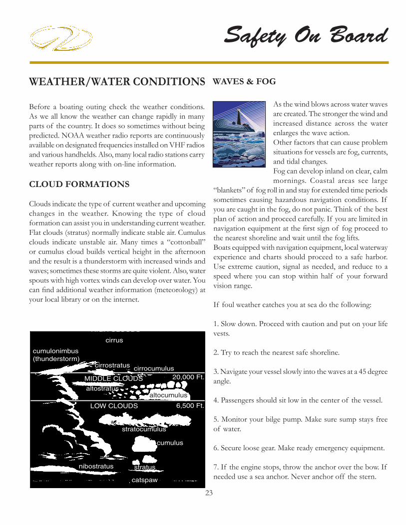
CLOUD FORMATIONS
Clouds indicate the type of current weather and upcoming changes in the weather. Knowing the type of cloud formation can assist you in understanding current weather. Flat clouds (stratus) normally indicate stable air. Cumulus clouds indicate unstable air. Many times a “cottonball” or cumulus cloud builds vertical height in the afternoon and the result is a thunderstorm with increased winds and waves; sometimes these storms are quite violent. Also, water spouts with high vortex winds can develop over water. You can fi nd additional weather information (meteorology) at your local library or on the internet.
20,000 Ft.
6,500 Ft.
HIGH CLOUDS
MIDDLE CLOUDS
LOW CLOUDS
catspaw
nibostratus stratus
cumulus
stratocumulus
cumulonimbus(thunderstorm)
cirrus
cirrostratus cirrocumulus
altostratusaltocumulus
As the wind blows across water waves are created. The stronger the wind and increased distance across the water enlarges the wave action.Other factors that can cause problem situations for vessels are fog, currents, and tidal changes.Fog can develop inland on clear, calm mornings. Coastal areas see large
“blankets” of fog roll in and stay for extended time periods sometimes causing hazardous navigation conditions. If you are caught in the fog, do not panic. Think of the best plan of action and proceed carefully. If you are limited in navigation equipment at the fi rst sign of fog proceed to the nearest shoreline and wait until the fog lifts.Boats equipped with navigation equipment, local waterway experience and charts should proceed to a safe harbor. Use extreme caution, signal as needed, and reduce to a speed where you can stop within half of your forward vision range.
If foul weather catches you at sea do the following:
1. Slow down. Proceed with caution and put on your life vests.
2. Try to reach the nearest safe shoreline.
3. Navigate your vessel slowly into the waves at a 45 degree angle.
4. Passengers should sit low in the center of the vessel.
5. Monitor your bilge pump. Make sure sump stays free of water.
6. Secure loose gear. Make ready emergency equipment.
7. If the engine stops, throw the anchor over the bow. If needed use a sea anchor. Never anchor off the stern.
WAVES & FOG

1
Rules Of The Road
NAVIGATION RULES DEFINED
The Navigation Rules set forth actions to be followed by boats to avoid collision. They are referred to as the “Rules of the Road”. There are two main parts referred to as the inland and international rules. The inland rules apply to vessels operating inside the boundaries of the United States. The international rules (referred to as 72 COLREGS) apply to vessels operating on the high seas and all connected waters outside the established demarcation boundaries. Most navigational charts show the demarcation lines by red dotted lines and are published in the navagation rules. Remember to consult state and local agencies since areas such as “no wake zones,” swimming beaches, “diver down fl ag” and inland landlocked lakes fall under their juristriction. This section is only an introduction to the “rules of the road”. We strongly recommend additional training before getting behind the “wheel” of your boat.
You can order the Inland & International Navigation Rules from:
Superintendent of DocumentsU. S. Government Printing Offi ceWashington, DC 20402Tel: (202-512-1800) Fax:(202-512-2250
NAVIGATION RULES
RIGHT OF WAY
1. Cross waves at right angles.
2. When caught in heavy water or squalls, head either directly into the waves or at a slight angle. Reduce speed, but maintain enough power to maneuver your boat safely.
3. Keep your speed under control. Respect the rights of other boaters engaged in all water sports. Give them plenty of operating room.
4. Whenever meeting a boat head on, keep to the right where possible.
5. When two boats cross, the boat to the right (starboard) has the right of way.
TO AVOID INJURY AND DEATH
FOLLOW THE NAVIGATION “RULES OF THE
ROAD” TO PREVENT COLLISIONS.
WARNING!
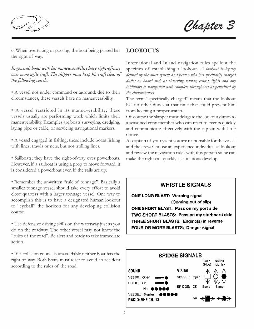
2
Chapter 36. When overtaking or passing, the boat being passed has the right of way.
In general, boats with less maneuverability have right-of-way over more agile craft. The skipper must keep his craft clear of the following vessels:
• A vessel not under command or aground; due to their circumstances, these vessels have no maneuverability.
• A vessel restricted in its maneuverability; these vessels usually are performing work which limits their maneuverability. Examples are boats surveying, dredging, laying pipe or cable, or servicing navigational markers.
• A vessel engaged in fi shing; these include boats fi shing with lines, trawls or nets, but not trolling lines.
• Sailboats; they have the right-of-way over powerboats. However, if a sailboat is using a prop to move forward, it is considered a powerboat even if the sails are up.
• Remember the unwritten “rule of tonnage”. Basically a smaller tonnage vessel should take every effort to avoid close quarters with a larger tonnage vessel. One way to accomplish this is to have a designated human lookout to “eyeball” the horizon for any developing collision course.
• Use defensive driving skills on the waterway just as you do on the roadway. The other vessel may not know the “rules of the road”. Be alert and ready to take immediate action.
• If a collision course is unavoidable neither boat has the right of way. Both boats must react to avoid an accident according to the rules of the road.
LOOKOUTS
International and Inland navigation rules spellout the specifi cs of establishing a lookout. A lookout is legally defi ned by the court system as a person who has specifi cally charged duties on board such as observing sounds, echoes, lights and any inhibitors to navigation with complete throughness as permitted by the circumstances. The term “specifi cally charged” means that the lookout has no other duties at that time that could prevent him from keeping a proper watch.Of course the skipper must delagate the lookout duties to a seasoned crew member who can react to events quickly and communicate effectively with the captain with little notice.As captain of your yacht you are responsible for the vessel and the crew. Choose an experiened individual as lookout and review the navigation rules with this person so he can make the right call quickly as situations develop.

3
Rules Of The Road
The Navigation Rules set forth 3 typesof crossing situations- crossing, meeting,and overtaking. In each case, both boatsare governed by special procedures.
In a head-on meeting, both vessels must sound a single blast to give way towardstarboard and pass to port.
These rules appear when there is a risk of collision. In a crossing situation beaware of the other craft's position. Forsafety, there should be a noticeable change in the angle, bow or stern; agradual change in position indicates pos-sible danger.
NAVIGATION RULES

4
Chapter 3
An overtaking boat is burdened, and is not the priveleged craft, even though it approaches the danger zone of the overtaken boat.
The overtaking boat fi rst signals with a single blast if that boat desires to pass on the starboard side of the boat ahead, or a double blast if passing to port. The overtaken craft responds with the same signal if safe, or with the danger signal (5 short blasts or more) if unsafe. The boat overtaking must not pass unless the appropriate signals are sounded.
NAVIGATION RULES

5
Rules Of The Road
NAVIGATION AIDS
Navigation aids are placed along coasts and navigable waters as a guide for mariners in determining their position in reference to land and hidden danger. Each aid provides specifi c information. They form a continous system of charted markers for monitoring on the plotter or providing accurate piloting on paper as a backup.Your on board plotter provides up to date navigation aids. Besides coastal maps a complete domestic interior waterway grid is featured on the plotter.If desired, there are hand-held GPS devices that are available as back-up devices. In addition, nautical charts are provided by the National Ocean Service (NOS) and are distributed nationwide through marinas and outlet stores. These charts show the geography of the coast, water depth, landmarks, navigation aids (buoys and markers), marine hazards, and port facilities. Use only up-to-date charts for navigation. We recommend when purchasing a chart to look for the weather resistant ones.Buoys provide a roadmap to keep the skipper on course and to avoid hazards. Buoys are identifi ed by light, shape, color and in severe weather conditions by sound.Buoys or beacons called lateral markers indicate the port and starboard sides of the waterway to be followed. U. S markers follow the buoyage system known as Red Right Returning. When returning from sea or traveling upstream, the green markers are to port (on your left) and the red markers are to the starboard side (on your right). When traveling downstream or out to sea the marker color would be reversed.Before operating your vessel, learn to identify the various navigational aids such as lateral aids, mid-channel markers, information and regulatory markers.
SKIPPERS MUST NOT RELY ON BUOYS
ALONE TO MARK THEIR POSITION.
SEVERE WEATHER CONDITIONS
AND WAVE ACTION CAN ALTER
A BUOYS POSITION.
NEVER TIE UP TO A BUOY.
IT IS ILLEGAL AND DANGEROUS.
NOTICE

6
Chapter 3
Port SideOdd Numbers
Lighted Buoy(Green Light Only)
Can Buoy(Unlighted)
Daymark Daymark
LATERAL AIDS
Starboard SideEven Numbers
Lighted Buoy(Red Light Only)
Nun Buoy(Unlighted)
Chart Symbol Chart Symbol
Chart Symbol Chart Symbol
Chart Symbol Chart Symbol

7
Rules Of The Road
Chart Symbol
Chart Symbol
Chart Symbol
Diamond ShapeWarns Of Danger
Diamond Shape With Cross-Boats Keep Out
Circle Marks Area Controlled As Indicated
For showing information such as locations, distances and directions
MID-CHANNEL MARKERS
REGULATORY MARKERS

8
Chapter 3
NIGHT RUNNING
Boats operating between sunset and sunrise ( hours vary by state), or in conditions of reduced visibility, must use navigation lights. Night time operation, especially during bad weather and fog, can be dangerous. All Rules of the Road apply at night, but it is best to slow down and stay clear of all boats regardless of who has the right-of-way. To see more easily at night, avoid bright lights when possible. Also, it is helpful to have a passenger (appoint as lookout) keep watch for other boats, water hazards and navigational aids.To determine the size, speed and direction of other vessels at night, you should use the running lights. A green light indicates starboard side, and a red light indicates port side. Generally, if you see a green light, you have the right-of-way. If you see a red light, give way to the other vessel.
BRIDGE CLEARANCE
Be aware that your vessel requires a specifi ed bridge clearance height. This height is a measured estimate from the waterline to the top of the highest equipment height. The estimated height can change because of variances in the loaded condition of the vessel and equipment variances. Consult the bridge clearance specifi cations located in Chapter 12 (Technical Information section). Some bridges are tendered. Know and use the proper bridge signals when approaching these bridges (see bridge signals in this chapter). You can also monitor and communicate on channel 13 of a VHF radio for bridge information in most domestic locals. Other bridges are marked with a clearance measurement and you are on your own. It is recommended that you have a look out posted for additional visual assistance when entering a bridge zone. After determining your vessel will clear the bridge proceed with caution at a safe idle speed. Keep your eye on vessel traffi c at all times in order to react quickly. Keep both hands on the helm since you may need to change course because of current and wind conditions. Resume a safe speed once clear of the bridge structure and acknowledgment of clear visibility.Just use common sense around any type of bridge structure!
BRIDGE LIGHTING
Bridge lighting is maintained by the Department of Homeland Security. On the following pages are 2 typical examples of night-time bridge lighting. As the skipper approaches bascule and fi xed bridges light position (arc of visibility) and color will indicate the safe channel through the bridge. Notice green denotes the “safe” entry location on single-span bridges and green or white on multiple-span bridges designates the main channel. In addition, green denotes the “up” position for single and double lift bridges.

9
Rules Of The Road

10
Chapter 3

1
Systems
OVERVIEWIn this chapter the Regal yacht on board systems are introduced. Information includes several main systems including fuel, electrical, air conditioning (AC), windlass, water, waste, electronics, entertainment, trim tabs and sun roof. This is the “meat and potato” section for equipment operation.A system description, location of components, operational information along with common problems and solutions are covered with each of the system components.
A portion of the photos and illustrations apply to earlier product. Be sure to read and follow any danger, warning, or caution labels in reference to the yacht’s systems or individual equipment components.Your Regal yacht may not contain all of the equipment or systems shown. Regal has the right to modify, update or delete equipment and/or systems at anytime. Refer to the vendor documentation located in the owner’s information packet for more detailed information of individual yacht system components.

2
Chapter 4
FUEL SYSTEM INTRODUCTION
In this section, the basic diesel fuel system components are introduced. The fuel system includes the fuel tank, fuel supply and return lines, fi ll and vent fi ttings along with fuel fi lters and the ventilation system. Diesel fuel today is processed in a different manner than it was a few years ago. As a result it has become more unstable and the product shelf life has been shortened. A summary of so called diesel fuel “algae” along with its causes and effects will be outlined in this chapter. As part of the Volvo product features the engines, EVC system and the transmissions are all protected by a fault handling system should a malfunction develop. A portion of this fault system is used to monitor the diesel fuel system. Select codes warn the captain with a “buzzer” sound while others will display on the helm tachometer, display, or alarm panel. The “pop-up” will alternate between the cause of the fault and a task to perform to aid in eliminating the situation.It is important to read and understand your Volvo propulsion owner’s manual in order to react to a fault code should a malfunction display on the instrumentation or an alarm sound.
PREVENT INJURY, DEATH, OR PROPERTY DAMAGE!READ AND UNDERSTAND
THE PROPULSION OWNER’S MANUAL BEFORE ATTEMPTING
TO OPERATE THE VESSEL.
WARNING!

3
Systems
DIESEL FUEL BASICS
Diesel fuel properties have changed in recent years due to the way the product is processed today at the refi neries. A couple of decades ago diesel fuel, gasoline, home heat-ing oil among other distillation products were processed by heating the crude oil. At different boiling tempera-tures, various parts of the crude oil were evaporated then condensed sending the fi nal products to storage tanks for distribution. The distillation process generally produced stable diesel fuel with a storage life of several months. Around 50% of the oil left over from the distillation pro-cess was designated as heavy fuel oil being used for ship’s, power plants, and industrial products such as nylon, plas-tics, and asphalt.Refi ning crude oil today has changed dramatically due to increased demand for the product. A process called “chemical cracking” has allowed the refi ner to extract more of the lighter distillates from the crude oil leaving about 16% of the residual as heavy fuel oils. Lowering the diesel fuel sulphur levels due to environmental concerns has led to further fuel instability. Due to these newer methods of refi ning diesel fuel is far less stable than the older distillation process. There are different theorems on defi ning fuel system “al-gae” and how it develops in the vessel’s fuel tank. Algae is slang for the fungus that grows in fuel tanks. One school of thought isolates two of the key fuel compo-nents. Asphaltenes and paraffi ns in this premise begin to oxidize and re-polymerize forming clusters resulting in fuel tank “algae”. As these clusters “grow” in size they cling themselves to tank walls and baffl es.Others state that “algae” is formed when water condenses in the boat’s fuel tank. Water can enter the vessel’s fuel tank through the fuel pumping process at the fuel dock since their tank may already be contaminated with algae-micro organisms. Once inside the tank these algae-mi-croscopic organisms from the plant kingdom are able to combine with water and diesel to form tank sludge. Keeping tanks free from water, dirt and micro organisms is almost impossible, but luckily you can eliminate them before they reach the engine and fuel injectors through the use of primary and secondary fuel fi lters. Algae ends up in the fuel system once the boat is running which breaks up the tank “algae” and/or sludge into mini clusters.
Using diesel fuel in this condition may cause the follow-ing:
Fuel tank sludge-remove manually or by chemicals• Dirty engine oil• Shortened engine component life• Smoke emitting from the engine exhaust system• Carbon deposits in the engine• Incomplete combustion • Loss of power and performance• Clogged primary and secondary fuel fi lters• Malfunctioning fuel injectors•
When this condition is present in the marine diesel fuel system the fuel does not combust rapidly as it should re-sulting in a loss of engine effi ciency. Basically, with either school of thought this “algae” or fuel tank sludge is the result of aging diesel fuel. It can occur in as little as 60-90 days depending on the condi-tion of the tanks and environment where the diesel fuel is stored.

4
Chapter 4
SOLUTIONS FOR RECOVERING DIESEL FUEL QUALITY
As a Regal yacht owner you have a huge investment in your diesel propulsion system. Being the engines are a key component in the system, keeping the fuel system clean is a high priority.Following are some solutions to help clean up a diesel fuel “algae” problem:Periodically use a biocide to control microbial activity which can lead to more rapid formation or clustering of solids such as wax and asphalt. Remember that biocides do not prevent microbes from forming but aid in break-ing up the clusters. If the vessel is to be stored for over 2 months pour biocide in the semi empty vessel fuel tank. Fill the fuel tank with fresh diesel fuel to prevent conden-sation build up. Run the boat for a short run to better mix the biocide inside the fuel tank and fuel system before storing the vessel.
Always make sure the fuel tank fi ll cap is securely 1. tightened to prevent any water infusion. Always buy diesel fuel from a marina or fuel dock that 2. moves a large amount of fuel through the pumps. Ask how often the fuel dock pump fi lters are changed and if their diesel fuel is blended with a biocide. Al-ways carry a couple of extra primary and secondary diesel fuel fi lters. Use exact replacements in order to match micron fi ltering capacity. Figure on changing both primary and secondary fuel 3. system fi lters more often due to today’s diesel fuel shorter storage life.Make sure to drain the 10 micron Racor water separa-4. tor fuel fi lter and the engine secondary fuel fi lter be-fore each outing. Look for sludge/water. Dispose of contaminated diesel fuel properly in approved con-tainers. Do not drain diesel fuel in the bilge.Never let diesel fuel remain in the boat’s fuel tank 5. for more than six months. The cetane value will drop which is its ability to ignite easily. Good grades of diesel support a cetane rating around 50. When the cetane level drops the engine is more diffi cult to start. The combustion process moves from a controlled burn to an explosion. Pump out the old diesel and replace with a fresh supply.
Old diesel fuel creates more stress on engine parts and produces more noise than normal resulting in the trade-mark diesel clatter. Pour a cetane booster and conditioner in the fuel tank-with the new batch of diesel fuel.
Note: In severe cases of “algae” the fuel tank may need to be pumped out. To remove the ability to generate new algae, the tank should be pressure washed which removes small deposits of “algae” from the baffl e system and hard to reach areas. Add a biocide (not a conditioner) and then top off the tank.
Remember: LESS AIR MEANS LESS WATER AND LESS GROWTH!

5
Systems
TYPICAL VENTILATION SYSTEM
Diesel engines require a continuous supply of fresh air in order to generate peak horsepower and rpm. Because diesel fuel is far less likely to explode it does not require a blower system like gasoline powered vessels to evacuate dangerous fumes.To deliver fresh air for the diesel engines a dual set of permanently mounted vents are integrated into the boat’s deck on both port and starboard sides. When the engines are started fresh air is drawn through the vent system. As the demand for air increases in rela-tionship to the engine revolutions per minute (rpm’s) the engine induction system supplies the required additional air supply by inhaling more air through the vents. Check the vents periodically for any obstructions or for-eign objects such as nests or spider webs. If the propul-sion system is running at a lower than normal cruising rpm or seems to lack power or the vessel is slow to plane check the fresh air supply to the engines including the engine air fi lters.
DECKVENT
CHECK FOR OBSTRUCTIONS

6
Chapter 4
TYPICAL DIESEL FUEL SYSTEM(46 SC)
FUEL TANKS
The fuel tanks are located in the engine room. Both the port and starboard fuel tanks feature shut-off valves for both engines and generator lines. The tank fi ll and vent connections are located at the forward end of the fuel tank .See the illustrations for further fuel system informa-tion.
FUE
L TA
NK
V
EN
T H
OSE
FUE
L TA
NK
FI
LL H
OSE
TYPICAL PORT FUEL TANK FEED LINES
GE
NE
RATO
RFE
ED
VA
LVE
FUE
L TR
AN
SFE
RFE
ED
VA
LVE
PORT
EN
GIN
EFE
ED
VA
LVE
FEED VALVESIN “ON” POSITION
TYPICAL STBD. FUEL TANK RETURN LINES
TYPICAL PORT FUEL TANK RETURN LINES
TYPICAL STBD. FUEL TANK FEED LINES
STBD
. EN
GIN
EFE
ED
VA
LVE
FU
EL
TR
AN
SFE
R FE
ED
VA
LVE
Note that the 42 SC features the same type of fuel line valves. It uses a single fuel tank located under the main cabin fl oor verses twin tanks in the 46 SC engine room.Knowing the basic fuel fl ow pattern may be helpful as a troubleshooting tool as well as general knowledge. In the event of a fuel leak the valves can be turned to the “off ” position.
TYPICAL STBD. FUEL TANK RETURN LINES
FUE
L TA
NK
FI
LL H
OSE
FUE
L TA
NK
V
EN
T H
OSE
EN
GIN
E
RETU
RN
EN
GIN
E
RETU
RN
GE
NE
RATO
R RE
TURN

7
SystemsTYPICAL FUEL TANK FILL/VENT
F u e l t a n k f i l l fi ttings are normally located on the deck. They are marked diesel. Never pump gasoline in a fuel tank designated for diesel fuel. After fueling use the fi tting key tool to close the fi tting tightly. Failure to
secure the fuel fi tting tightly may allow water to enter the fuel tank and eventually the engine fuel system. Periodically lubricate the fuel fi tting O-ring by coating with clean diesel fuel. This will help keep the O-ring pliable and retain its sealing properties.The fuel vent serves as a pressure relief for the diesel tank and is a safety overfl ow device. The vent is found below the fuel fi ll fi tting at the starboard hull side. It has a screen inside which needs to be periodically cleaned. Insects can cause the vent to clog resulting in increased pressure in the fuel system especially noticeable when fi lling the fuel tank. In extreme clogging cases the fuel will emerge from the fi ll because the vent is not able to relieve the air in the fuel tank that is being replaced with diesel fuel.
Placed near the aft top of the fuel tank is an elec-tronic fuel sender. This device reads the amount of fuel re-maining in the fuel tank
and sends a signal to various displays includ-ing the fuel gauge located at the helm (dash). Always use the one-third rule with diesel fuel. One-third for outbound cruising, one-third for inbound cruis-ing, and the remaining one-third fuel supply for reserve.
TYPICAL FUEL SENDER
PREVENT INJURY, DEATH, ORPROPERTY DAMAGE!
INSPECT THE FUEL SYSTEMPERIODICALLY FOR LEAKS,
LOOSE CLAMPS OR FASTENERS.
WARNING!
DIESEL FILL FITTING
DIESEL VENT FITTING

8
Chapter 4
TYPICAL DIESEL FUEL SYSTEM FILTERS
Regal yachts feature a primary and secondary fuel fi lter system to provide maximum engine protection. Both en-gines offer an in-line 10 micron Racor water separator fi lter which is the fi rst line of defense. In addition, Volvo provides a secondary fi lter mounted on the engine for enhanced protection from water, dirt and “algae” micro organisms/clusters.
To Drain Racor Water Separator Filter
The Racor diesel fuel fi lter should be drained frequently and checked for water and other contaminants as needed:
Place fi lter fuel valve in the “off ” position which is 1. perpendicular (90) degrees to the fuel lines. Failure to turn valve off may allow a continuous fl ow of fuel due to siphoning.Place a suitable container below the fi lter bowl assembly 2. to catch the contaminants.Remove drain plug at the bottom of the fi lter bowl 3. assembly. Drain the contaminants. Replace the drain plug.Replace the drain plug. See section on “priming.4.
Examine the diesel fuel in the drain container. Water is heavier than diesel fuel and will be noticed as a different color on the bottom. If water is present tilt the pan and any water will move on the bottom. In extremely humid conditions, the fuel system may require daily checks and draining of water. ALWAYS CARRY EXTRA FUEL FILTERS AS EVEN ONE TANK OF CONTAMINATED FUEL CAN PLUG A FUEL FILTER. USE EXACT REPLACEMENTS ONLY.
To Prime Racor Water Separator Filter
Loosen the air vent plug on the top right side of the 1. fuel fi lter.Operate the primer valve until diesel fuel emerges from 2. the air vent plug free of air. In some cases, multiple pumping is required depending on the amount of air in the fuel system. Also, it is a good idea to prime the engine secondary fi lter as air could be trapped in the lines.Close the air vent plug and tighten securely.3. Start the engine and check for leaks. If the engine is 4. diffi cult to start or is rough running check to see that all connections are tight and there are no kinked fuel lines.
RACOR WATER SEPARATOR DIESEL FILTER
FUEL SHUT-OFF VALVE
AIRVENT
DRAINPLUG
PRIMERVALVE
3
2
1
1=Head Assembly2=Element3=Metal Bowl Assy.
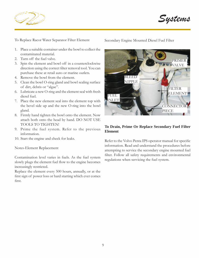
9
Systems
To Replace Racor Water Separator Filter Element
Place a suitable container under the bowl to collect the 1. contaminated material.Turn off the fuel valve.2. Spin the element and bowl off in a counterclockwise 3. direction using the correct fi lter removal tool. You can purchase these at retail auto or marine outlets.Remove the bowl from the element. 4. Clean the bowl O-ring gland and bowl sealing surface 5. of dirt, debris or “algae”.Lubricate a new O-ring and the element seal with fresh 6. diesel fuel.Place the new element seal into the element top with 7. the bevel side up and the new O-ring into the bowl gland. Firmly hand tighten the bowl onto the element. Now 8. attach both onto the head by hand. DO NOT USE TOOLS TO TIGHTEN!Prime the fuel system. Refer to the previous 9. information.Start the engine and check for leaks.10.
Notes-Element Replacement
Contamination level varies in fuels. As the fuel system slowly plugs the element fuel fl ow to the engine becomes increasingly restricted. Replace the element every 500 hours, annually, or at the fi rst sign of power loss or hard starting which ever comes fi rst.
Secondary Engine Mounted Diesel Fuel Filter
PRIMERVALVE
BLEEDNIPPLE
CONNECTORPIECE
FILTERELEMENTFUEL
INLET
To Drain, Prime Or Replace Secondary Fuel Filter Element
Refer to the Volvo Penta IPS operator manual for specifi c information. Read and understand the procedures before attempting to service the secondary engine mounted fuel fi lter. Follow all safety requirements and environmental regulations when servicing the fuel system.

10
Chapter 4TYPICAL DIESEL FUEL TRANSFER PUMP (46 SC ONLY)
A diesel fuel transfer pump is available to equalize and to balance fuel supply. The transfer pump switching mechanism is located at the helm, while the pump itself is normally found on the forward engine fi rewall. Hoses and pickup tubes located in the fuel tank permit the fuel to travel between the tanks. One hose is always drawing and the other hose is fi lling when the transfer switch is enerigized. The pump utilizes a three position, center off style switch. Simply press the transfer switch located at the helm toward the fuel tank you want to add the fuel. During the cruise, monitor the fuel gauges until the tanks are equalized. The system only requires periodic inspection of hose clamps for tightness.
Note: You may fi nd this feature useful if you were stopped and running the generator for extended periods. Since the generator normally draws its fuel from the port fuel tank it may show that the port tank is a bit lower than the starboard tank.Also, somethimes one engine will burn more fuel than the other when cruising over extended periods.
FUEL TRANSFERPUMP
FWD. ENGINEFIREWALL
Note that the diesel fuel transfer pump is used on the 46 SC only as the 42 SC utilizes a single fuel tank and there-fore equalization of fuel levels is not needed.
11
Systems
POSSIBLE FUEL PROBLEMS/SOLUTIONS
1. Engines are hard to start or rough running- This problem can be caused by air in the fuel system or a restriction in the fuel supply which causes a lean condition.
Check all fuel system lines, clamps, fi ttings and fi lters for tightness. Prime and bleed the fuel fi lters if necessary.
2. Fuel fi lter elements contain “algae” or exhibit a brown or black color and/or show water in the fuel system.Check fuel tank for “algae” clusters. Fuel tank may require pumping out and a cleaning with a pressure washer or a biocide being added to “kill” existing organisms which may be caused by water in the fuel system and fuel tank. Replace all fi lter elements and top the tank with fresh diesel fuel. Prime and bleed the system. Run the engines and check for fuel leaks and restrictions along with the possibility of further contamination moving within the fuel system lines and/or components. It may be necessary to replace diesel fuel system fi lter elements several times to rid the system of contaminants.
3. The fuel tank reads low and the engines are running rough. The pick-up tubes in the diesel fuel tank have sucked up air instead of fuel. The air has meandered through the fuel lines, fi lters and is effecting the engine performance. Top off the fuel tank as soon as possible. Also, the fuel system must be bled and primed.Another possible result of running with a near empty fuel tank is the same pick-up tubes sucking water into the fuel system. Remember water is heavier than diesel fuel and will hug the tank bottom or baffl e areas. Take a sampling of diesel fuel to identify water in the fuel system.
4. Recommissioning after 6 months of winter storage with a full diesel fuel tank the engines are hard to start and exhibit a diesel clatter noise.The diesel fuel in the tank may have deteriorated due to its age. The cetane value may have decreased causing more of an explosion inside the cylinder verses a controlled burn. To start with add a cetane booster and conditioner. If this fails take a sampling of diesel system fuel at the fi lters.The diesel fuel in the tank may have deteriorated due to its age. The cetane value might of decreased causing more of an explosion inside the cylinder verses a controlled burn. To start with add a cetane booster and conditioner. If this fails take a sampling of diesel system fuel at the fi lters to determine contamination levels.As a last resort pump out the fuel tank and replace with fresh, clean diesel fuel.

12
Chapter 4
ELECTRICAL INTRODUCTION
In this section, basic DC (direct current) and AC (alternating current) electrical systems are introduced. Each electrical component is reviewed along with its location and function within the Regal yacht electrical system. For more complicated issues outside the scope of this manual contact your closet Regal yacht dealer. They have undergone extensive training on the Regal yacht systems.Be sure to read and follow any danger, warning, or caution labels in reference to the yacht’s electrical system or individual equipment components.
PREVENT SEVERE INJURY OR DEATH!DISCONNECT
ALL ELECTRICAL POWER SOURCES BEFORE ATTEMPTING
TO REPAIR OR REPLACE ANY ELECTRICAL COMPONENTS.
WARNING!

13
Systems
Your Regal yacht uses 12 volt DC electricity otherwise known as direct current. It is called DC because it fl ows only one way in a circuit. Specifi cally to name a few, helm gauges, batteries, battery cables, engine electrical components, engine wiring harnesses, dash switches, selected lighting, shower sump, bilge pumps, and vacuum toilets are all components using a 12 volt DC system. In the DC system used in the United States the red wire is designated as the “hot” or conductor wire and the black wire is referred to as the ground wire. At times other current carrying wires are color coded such as blue to identify their use as a low voltage conductor. This is especially helpful in troubleshooting and adding additional equipment. Be sure to review the wiring schematics in the drawing section of the technical chapter.Direct current is stored in the ship’s batteries and produced through the engine alternators while the engines are running or by the battery charger at dockside. The alternators charge the batteries by sending current through the main distribution panel relays, battery switches and harnesses to the appropriate battery. Normal DC voltage is between 12 and 15 volts. Lower or higher readings could indicate a charging malfunction or a weak battery.The Volvo diesel engine alternators used on your yacht are internally self “excited” and produce DC current at idle.Current specifi cations for alternator output is 115 amps. The IPS steering system needs additional operating current and this is one reason the alternator output is higher than conventional units.
The port cranking battery controls the windlass, port engine and generator.The starboard battery controls the starboard engine The house battery controls a variety of onboard equipment.
DIRECT CURRENT (12 VOLTS) BATTERY (12 VOLTS) DESCRIPTION
On board direct current is stored in the ship’s “wet cell” batteries. There are 2 engine starting batteries (one for each engine) and a deep cycle “house” battery.
BATTERY SPECIFICATIONSBattery Type
Group CCA @32Degrees F.
ReserveCapacity
Engine Cranking
31A 1260 195 min.
House 8D 1700 430 min.
BATTERY TERMINOLOGY
Group- Batteries are divided into groups which identify the height, length, and width of the battery. This is useful information should a replacement battery become neces-sary.
Cold Cranking Amps (CCA)- This rating measures the cranking power a full charged marine battery has available to start at 32 degrees F. Basically, the higher the rating the greater starting power of the battery.
Reserve Capacity (RC)- As usage on the boat increases so does the need for more reserve capacity. The reserve capacity represents the length of time in minutes a new fully charged battery can maintain the yacht’s electrical needs without the engine running or in the event the al-ternator fails.
T Y P I C A L ENGINE
STARTING BATTERY
TYPICAL HOUSE
BATTERY
BATTERY BOOT
REMOVECAP
REMOVECAP
14
Chapter 4
POSSIBLE PROBLEMS/SOLUTIONS
1. Weak battery- This battery problem can be caused by low electrolyte cell levels. Warm, engine compartment temperatures will deteriorate a battery’s life quicker by evaporating the water from the electrolyte,
thus corroding and weakening the positive grids inside the battery. With the house battery low electrolyte levels can be monitored by periodic inspection and fi lling as needed with distilled water. Boaters in higher climate areas with longer stretches of hot weather will need to check their batteries more often.The “maintenance free” engine cranking batteries require no water. They do feature a different chemistry that does consume less water. Inside the cells as gases are released condensation is formed which aids in maintaining the cell electrolyte level. These batteries incorporate a deeper layer of electrolyte over the plates, but eventually it can run dry. On the 31 series engine cranking batteries keep all terminals clean, connections tight and your electrical system in top shape to extend the battery life.
2. Dead Battery- Either the battery will not accept a charge, hold a charge or the charging system is not supplying a charging current through the battery charging system and/or engine alternators. The battery charger output can be checked by monitoring the lights on the charger front face.To begin with check the battery post connections for tightness and corrosion.With the engines running the displayed voltage of the port or starboard engine battery and house battery should be between 12.5 up to 14.6 volts. If less than 12 volts check for voltage across the battery terminals. If less than 12 volts on the house battery use a hydrometer to locate faulty cells. On maintenance free batteries they can be removed from the vessel if necessary and trickle charged. If readings after charging are still low replace the battery.
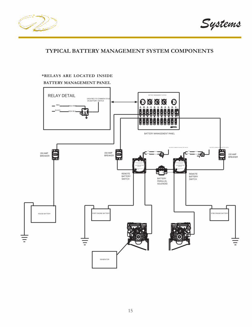
15
Systems
TYPICAL BATTERY MANAGEMENT SYSTEM COMPONENTS
PO
RT
D
+
C
OFF
_
OFF
HO
US
E
+
B
_
ST
BDOFF
A
B
+_
80AMP
ON
ON
5AMP
OF
F
PUMP
CHARGER
FWD SHOWER
OF
F
OF
F
WINDLASS
150AMP
SHOWER
ON
OF
F
ON
OF
F
5AMP
PUMP
DASH MAIN
MID BILGE
ON
RELAY DETAIL
HOUSE BATTERY
ON
ON
ON
ON
LIFT
RED
BLACK
PORT ENGINE BATTERY
GENERATOR
90AMP
HATCH
20AMP
ELECTRONICS
CHARGER
20AMP
MASTER
OF
F
20AMP
CABLE
OF
F
14GA RED TO COMMON STUD ON BATTERY SWITCH
18GA RED
18GA BLK 8587
87A86
30
OIL
CABIN MAIN
80AMPO
NO
FF
30
80AMP
OF
FO
N
PUMPFWD BILGE
OF
F
OF
F
10AMP
PUMP
10AMP
OF
F
OF
FO
N
OF
FO
N
80AMP
ACC
ON
60AMP
OF
F
TENDERWINCH
ON
ON
ON
ON
PUMP
10AMP
OF
F
AFT BILGEALARM
5AMP
OF
F
HIGH WATER
25AMP
OF
FO
N
LIFTTENDER
ON
30AMP
OF
F
GANGWAY
SHOWERMEMORY
OF
F
10AMP
STEREOPUMP
OF
F
5AMP
CHARGER
OF
FO
N
80AMP
CHARGER
OF
FO
N
80AMP
A
BATTERY MANAGEMENT SYSTEM
858687
87A
14GA REDTO COMMON STUDON BATTERY SWITCH
STBD ENGINE BATTERY
18GA BLK
18GA REDRED
BLACK
14GA REDTO COMMON STUDON BATTERY SWITCH
BATTERY MANAGEMENT PANEL
8586 87A
87
30
RED
BLACK 18GA BLK
18GA RED
BATTERYPARALLEL SOLENOID
150 AMP BREAKER
150 AMP BREAKER
150 AMP BREAKER
REMOTEBATTERYSWITCH
REMOTEBATTERYSWITCH
VSR
DUAL SENSE
CUT OUT 12.8V DCCUT IN 13.7V DC
VSR
RELAY MODULEVOLTAGE SENSITIVE
IGNITION PROTECTED
125 AMP
CUT IN 13.7V DCCUT OUT 12.8V DC
IGNITION PROTECTED
VOLTAGE SENSITIVERELAY MODULE
DUAL SENSE125 AMP
ONOFF
NOTE!
300AMARINE
BEP
EMERGENCY
LED ON - BATTERY SWITCH ON BY REMOTE
CONTINUOUS RATING
WHEN RETURNING TO AUTO OPERATION AFTER MANUAL ON OPERATIONTHE HANDLE MUST BE SWITCHED TO OFF POSITION THEN TO AUTO.
FOR AUTO OPERATION HANDLE MUST ALIGN TO AUTO.
ELECTRIC BATTERY
OVERRIDE
LED INDICATIONS: LED OFF - BATTERY SWITCH IS OFF
SWITCH
AUTO
FOR AUTO OPERATION HANDLE MUST ALIGN TO AUTO.
â
ONEMERGENCYOVERRIDE
AUTO
NOTE!
OFF
WHEN RETURNING TO AUTO OPERATION AFTER MANUAL ON OPERATIONTHE HANDLE MUST BE SWITCHED TO OFF POSITION THEN TO AUTO.
MARINE
BEPâ 300A
LED ON - BATTERY SWITCH ON BY REMOTE
CONTINUOUS RATING
LED INDICATIONS: LED OFF - BATTERY SWITCH IS OFF
ELECTRIC BATTERYSWITCH
150A 150A150A
PARALLELSOLENOIDINSIDEBOX
*RELAYS ARE LOCATED INSIDE
BATTERY MANAGEMENT PANEL

16
Chapter 4
REMOTE BATTERY SWITCH OPERATION
Under normal conditions with the vessel charging sys-tem working properly each remote battery switch should show a lighted LED on the faceplate. When the remote-battery switch is in the “OFF” position the LED is not lighted. The manual override switch should be located in the AUTO position. Read and understand the notice be-low.
NOTICEIF THE REMOTE BATTERY SWITCH IS TURNED TO THE “OFF” POSITION THE
ENGINE WILL NOT CRANK.TURN THE REMOTE BATTERY SWITCH TO
THE “ON” POSITION FOR THE ENGINE TO CRANK.
NEVER TURN THE REMOTE BATTERYSWITCH OFF
WHEN THE ENGINE IS RUNNING!
TYPICAL REMOTE BATTERY SWITCH
As part of the battery management system remote battery switches are located in the engine room. A remote battery switch is wired between each engine and the “on-off ” universal battery switches located at the battery management system panel. See the illustration. Their purpose is to break up the long battery cable runs from the batteries to the management center panel. Also, they offer a shorter run from the battery to the starter motor. In addition, the remote battery switch from the bilge (sump) provides an avenue to shut down the battery system during engine or sump routine maintenance functions.
If the remote battery system fails the skipper can turn on the remote battery switch manually through the manual override switch located on each remote battery switch which will generate power for engine starting.Each remote battery switch provides a continuous rating of 300 amps DC and a cranking rating of 1250 amps DC. Both remote battery switches are “in line” between each battery and the engine.
TYPICAL REMOTE BATTERYSWITCH
TYPICAL BREAKER

17
Systems
TYPICAL RELAY FUNCTION
The previous management system drawing shows a relay (located inside battery management panel) wired between each remote battery switch and the appropriate univer-sal “ON-OFF” battery switch at the battery management panel. The purpose of the relay is to provide a complete circuit for the remote battery switch. When the port or starboard universal battery switch on the battery manage-ment panel is activated the remote battery switch circuit is closed allowing the appropriate engine to be started at the helm. The relay closes when the ON-OFF universal battery switch is energized. In theory, the relay switches “on” the ground circuit of the electric battery switch not the “hot” side.
POSSIBLE PROBLEMS/SOLUTIONS
1. The engine does not crank over. Relay is defective causing an open ground circuit- Open the battery man-agement panel and by-pass the relay by
pulling the wire off the 87A relay terminal and touch it to the 87 terminal. Have someone crank the engine at this point (Stand clear of any moving engine parts). If the engine cranks contact your closest Regal yacht dealer for replacement parts.
2. The engine does not crank over. Check relay for cor-rosion or loose connection.
POSSIBLE PROBLEMS/SOLUTIONS
Some of the more common problems with the remote-battery switch could be:
1. Engine will not crank over- The re-mote battery switch is in the “off ” posi-tion. Reposition the remote battery selec-tor switch to the “on” position.
2. Remote battery switch in “on” position but en-gine will not crank over- Make sure the universal bat-tery switch on the battery management panel is “on” to provide power to the helm. Check the appropriate battery connections for corrosion and tightness. Check battery with volt meter as described earlier and a hydrometer if needed. If battery is determined to be weak press the bat-tery parallel switch to crank the engine over or start the generator which will initiate charging of the weak bat-tery.

18
Chapter 4
TYPICAL BREAKER
As part of the battery circuit protection from the bat-tery to the battery management system panel a 150 amp breaker is installed within 40” of the battery. These break-ers are located in the bilge. If the breaker would draw excessive amperage it is pos-sible it could “blow”. At this point it would need to be reset. Always determine the reason why the breaker blew be-
fore resetting the breaker.To reset the break-er move the lever from the “off ” position to the “on” position as indicated by the red arrow above.
POSSIBLE PROBLEMS/SOLUTIONS
1. One of the three universal battery switches and breakers at the battery management panel do not function- The breaker is blown. Reset the 150 amp breaker after determining the cause of the problem.
2. One of the 150 amp breakers has blown- it is possi-ble that the circuit has drawn excessive amperage. Check the circuit components and wiring before resetting the breaker.

19
Systems
PREVENT INJURY, DEATH, ORPROPERTY DAMAGE FROM HIGH VOLTAGE!
DISCONNECT THE AC POWER SUPPLY BEFORE ATTEMPTING TO BEGIN ANY BATTERY CHARGER SERVICE WORK.
WARNING!
TYPICAL BATTERY CHARGER
The yacht battery char-ger features 50 amp output and universal voltage for 3 battery circuits. This means that the battery char-ger will operate from 95 volts through 277 volts either at 50 or 60 Hz. This is helpful on docks that carry lower voltage. The new elec-tronic battery chargers are “smart”. They will charge the batteries in 3 stages; bulk, absorp-tion, and fl oat formats. The charger is desig-
nated to get the maximum life out of your batteries, using micro computer controlled charging. It is recommended to keep the battery charger “on” at all times when AC power is available for maximum battery life. We recommend checking the battery water level weekly.The charger is factory set to charge fl ooded lead acid batteries which are the most common type available. The charger can be reprogrammed to take gel cell or AGM batteries.In the event the boat is switched over to different battery designs, it is important that all batteries are changed over to the same type.
Remember, changing to a different battery type requires re-programming the charger. Do not mix different de-signed batteries because they need different charging rates and voltages.During bulk charge the battery charger brings up the bat-tery charge state quickly, as the battery nears fully charged, it switches over to absorption charge. Absorption charges at a lower rate than bulk, until the battery is just a few % away from full charge.The battery charger display includes functional LED information for charge current, charge voltage, charge phase (bulk, absorption, fl oat), battery content measure-ment and/or battery condition measurement as a % of Ah capacity.It is recommended that an ABYC certifi ed electrical tech-nician perform any repairs or service. Do not attempt to open the battery charger casing.
Refer to the vendor information for more detailed instruc-tions.

20
Chapter 4
VSR (VOLTAGE SENSITIVE RELAY)
Located on the battery management panel above and below the battery switches are 2 VSR’s (voltage sensi-tive relays). The purpose of the VSR is to protect the engine batteries from being discharged. Also,
when the engine batteries are fully charged it sends current to charge the house battery. When the cranking battery(ies) rise above 13.7 volts DC the VSR switches to charge (cranking and house) both bat-teries in parallel simultaneously. When the battery voltage drops to 12.8 volts DC the VSR disengages. This VSR capability is referred to as “dual sense”. This permits the VSR to sense the voltage of both batteries that it is connected between. If one of the batteries is receiving a charge the VSR will close by paralleling both battery banks to charge the house battery along with the 2 engine cranking batteries. Notice the illustration shows a LED light which indicates when lite that the VSR is closed and is sending a charging current to a battery(ies).If the VCR senses the engine batteries are being discharged at a fast rate it will open and will not allow those batteries to be overly discharged to the point that the engines will not crank over. An example of the above situation would be if the vessel was stationary at sea for an extended period with various electronic and entertainment equipment energized along with the engines and generator off the batteries would normally discharge.
POSSIBLE PROBLEMS/SOLUTIONS (VSR)
1. Red LED light not visible at VSR- One cause could be the remote battery switch is not energized.
2. Red LED light stays on after the engine is turned off- This is a normal
condition. The residual battery voltage because of bat-tery charging has not yet dropped below 12.8 volts for the VSR to cut out.
Red LED light

21
Systems
TYPICAL CHARGING SYSTEM- SUMMARY NOTES
Following is a summary regarding the yacht charging sys-tem or specifi c charging system components.
1. With the battery charger unplugged from shore pow-er the battery charger is not generating any DC power. However, the battery charger is connected to the batteries through the battery switches and charger breakers which are located on the battery management panel. The char-ger breakers would stop any short in the wires that run directly to the battery charger. Remember that the char-ger is connected to the battery side of the switch and is continuously “hot”. 2. There is a breaker protecting the battery charger cir-cuit. A primary cause of the breaker to “trip” would be if the positive and negative battery cables were crossed. The above situation could easily happen if someone was trying to jump start a battery with “jumper cables.” To a lesser degree should a wire delivering current from the battery charger chafe a fuse may “blow” and the battery charger would cease its charging operation. See your Re-gal dealer for ordering extra fuses for your charger.
2. If one of the cranking batteries is weak or “dead” fi rst start the generator up and let it run awhile as it will send an initial charge to the weak battery. Then engage the bat-tery parallel switch to start the engine.
3. Always turn the universal battery switches on the bat-tery management panel to the “off ” position when leav-ing the vessel for extended periods. Select breakers that control specifi c safety functions of the boat will operate as normal.
4. When leaving the vessel after connecting your dock-side power cord turn the battery charger breaker at the management panel to the “on” position. This will permit the battery charging system to energize the appropriate batteries as needed.
5. The Bosch relay located inside the battery management panel is connected to the remote battery switch. It closes when the universal battery switch is activated at the bat-tery management panel. Remember the appropriate en-gine will not crank over with the universal battery switch in the “off ” position.
6. An internal battery charger fuse protects the entire cir-cuity from reverse connections. For example, if someone was attempting to “jump” start an engine and had the polarity reversed on the jumper cables this action may cause the internal fuse to “blow” thus making the charger inoperative. Bottom line- always remove a battery if using a trick-le charger. It is not recommended to jump start using booster cables.

22
Chapter 4
BATTERY PARALLEL SWITCH
The battery parallel switch is connected through the engine ignition switches to each of the engine cranking batteries. If one of the en-gine cranking bat-teries is weak this system will use the good battery from the one engine to provide cranking power for the weak battery of the other engine.
It is always recommended to let the weak battery recharge awhile before using the battery parallel switch. This can be done by using dockside power or by running the genera-tor. This process will supply some initial charging energy to the weak battery. It is even more important to follow the above procedure if the battery is “dead.”To activate the battery parallel switch fi rst start the engine with the charged battery. Let the engine run for a few minutes. Now depress the battery parallel button while simultaneously cranking over the weaker battery’s engine. After the engine starts release the button mechanism.
DEPRESS BUTTONTO ACTIVATE

23
Systems
TYPICAL ENGINE IGNITION SWITCH
On select yachts dual ignition switches are used to crank over and start the diesel engines. The left ignition switch controls the port engine and the right ignition switch con-trols the starboard engine. Other yachts use the newer Volvo “E” key system.
Each ignition switch features 3 positions.
STOP- SPRING LOADED TO THE LEFT.
ON- SUPPLIES IGNITION POWER TO ENGINE.
START- SPRING LOADED TO THE RIGHT.Each ignition switch features 3 positions.Refer to the engine chapter for further information.
Other yachts use the E-key system for starting engines.
Note: See the engine operatior’s manual for additional de-tailed information.
WARNING!AVOID POSSIBLE BODILY INJURY OR DEATH!
REMOVE KEYS FROM THE IGNITION SWITCHES WHEN THE ENGINES
ARE NOT RUNNING.

24
Chapter 4
TYPICAL BATTERY MANAGEMENT SYSTEM
The battery management sys-tem is an important ingredient of the yacht’s 12 volt direct cur-rent (DC) system. The battery management panel consists of 3 universal battery switches along 3 Boesch relays, 2 VSR’s and 2 banks of DC breakers plus the wiring itself. Refer to the battery management information chart in this section and the techni-cal chapter for a breaker am-perage listing. Be aware that in some cases the breaker protects a component; in other cases it may control a sub-panel or parts of a sub-panel.The universal battery switch marked port is part of the port engine cranking battery circuit. The universal battery switch marked starboard is part of the starboard engine battery circuit. Likewise, the switch marked house is part of the “house” battery circuit. The port VSR is connected to both the port cranking battery and the house battery. The starboard VSR
is connected to the starboard cranking battery and the house battery.

25
Systems
TYPICAL BATTERY MANAGEMENT SYSTEM-COMPONENT BREAKER DESCRIPTION
DASH MAIN- protects dash operation switch functions, hardtop control panel, and engine hatch panel. In addi-tion, it controls components located on the helm breaker sub-panel located in the main stateroom electronics lock-er. See the illustration for more information.Volvo engine functions are not controlled by the dash main breaker.
CABIN MAIN- protects the cabin main DC panel which controls direct current switch functions through-out the vessel.
ELECTRONICS- protects all electronic dash equip-ment components along with the stereo components. In addition, this breaker controls all breakers from the elec-tronics through the sirius weather on the helm breaker panel located at the starboard helm seat locker.
WINDLASS- protects the deck mounted anchor wind-lass circuitry.
CHARGER- This breaker protects the port battery charger circuitry.
CHARGER- This breaker protects the “house” battery charger circuitry.
CHARGER- This breaker protects the starboard battery charger circuitry.
ACC (ACCESSORY)- protects any add-on equipment components. If adding components ensure that the am-perage does not exceed the safe limits of the breaker.
HYD. LIFT- protects the middle bilge pump circuitry.
CABLE REEL- protects the optional shore power hose reel.
HOSE REEL- Protects the optional hose reel wash-down system.
OIL CHANGER- protects the engine and generator oil changer pump circuitry located in the bilge.
HATCH LIFT- protects the aft engine hatch circuitry.
FWD. BILGE PUMP- protects the forward most bilge pump.
AFT BILGE PUMP- protects the aft bilge pump lo-cated in the engine room under the center diamond plate fl oor section between the engines.
HIGH WATER ALARM- protects the bilge high wa-ter alarm. This audible alarm sounds at the dash should bilge water reaches a predetermined level. Normally this would indicate large volumes of water are entering the bilge since normal amounts would be drawn overboard via the bilge pump system.
STEREO MEMORY- protects the stereo system mem-ory circuit and the stereo unit itself.
SHOWER PUMP- protects the aft/forward shower sump pump circuitry.
POWER SEAT- protects the helm seat up/down along with the forward/aft circuitry.
HOSE REEL- Protects the optional hose reel wash-down system.

26
Chapter 4
NOTICEAS A SAFETY FEATURE
THE FORWARD AND AFT BILGE PUMP CIRCUITS ALONG WITH THE HIGH WATER ALARM ARE CONTINUOUSLY “ON” EVEN
WITH THE UNIVERSAL BATTERY SWITCHES IN THE OFF POSITION.
The battery management system panel breaker circuitry employs a lighted icon for each breaker. When lighted that circuit is energized and protected.
With all 3 universal battery switches in the “off ” position the following common breaker circuits are considered “on” and should show a lighted icon above the breaker name. These are the common breakers that will be “on” when you normally leave the vessel for extended periods of time.
ALL 3 UNIVERSAL BATTERY SWITCHES “OFF”
1. 3 battery charger2. Fwd. bilge pump3. Aft bilge pump4. High water alarm5. Stereo memory6. Shower pump
Other possible universal battery switch positions are:
“HOUSE” UNIVERSAL BATTERY SWITCH ONLY “ON”
1. All breakers “on” except for windlass and accessory
“PORT” UNIVERSAL BATTERY SWITCH ONLY “ON”
1. Common breakers plus accessory and windlass
“STARBOARD” UNIVERSAL BATTERY SWITCH ONLY “ON”
1. Common breakers and cable reels. No additional break-ers “on”.
PREVENT POSSIBLE FIRE/EQUIPMENT DAMAGE!
NEVER TURN THE UNIVERSAL BATTERY SWITCHES TO THE “OFF” POSITION WHILE
THE ENGINES ARE RUNNING.
WARNING!
Note: As stated above the 115 amp diesel engine alter-nators or electronics may be damaged from the current spike created by turning off a universal battery switch with the engine running.

27
SystemsPOSSIBLE PROBLEMS/SOLUTIONS
1. It is possible that one of the battery management system breakers may trip from long-term arcing and heat.The breaker may need to be reset- This might happen occasionally with one of the battery charger breakers. To trip and
reset this style of breaker do the following:
A. Take a small slotted screw-driver from your on-board tool kit and insert it in the breaker slot until it trips. You will hear a snapping type noise. See the illustration.
B. Notice that the breaker has pushed outward from its origi-nal fl ush position indicating the breaker has been tripped. See the illustration.
C. To reset the breaker use your fi nger to press the breaker down until it locks in the “on” position. You may hear a slight noise. This is normal. The icon light should be lighted after this procedure. See the illustration.
2. Breaker will not reset- Replace the breaker. Contact the nearest Regal yacht dealer for replacement parts.
3. Breaker continues to “trip”. Check the affected equipment to determine if it is responsible for the exces-sive draw to trip the breaker. If the equipment is deter-mined to be within specifi cations check for a “short” in the wiring circuit. Also, the breaker may be faulty. Con-tact the nearest Regal yacht dealer.

28
Chapter 4B
AT
TE
RY
MA
NA
GE
ME
NT
PA
NE
L W
IRIN
G S
PE
CIF
ICA
TIO
NS
COM
PON
EN
TSBK
R. S
IZE
% V
OLT
AGE
-D
ROP
WI
RE
G
AUG
EW
IRE
CO
LOR
WIR
E R
UN
LEN
GTH
POW
ER
SOU
RCE
24 H
OU
RS M
ON
ITO
RIN
G
OR
SWIT
CHE
DBA
TTE
RY S
WIT
CH P
ORT
PORT
EN
G. B
ATTE
RYBA
TTE
RY S
WIT
CH H
OU
SEH
OU
SE B
ATTE
RY B
AN
KBA
TTE
RY S
WIT
CH S
TBD
.ST
BD. E
NG
INE
BAT
TERY
VSR
RE
LAY
PO
RTPO
RT E
NG
INE
BAT
TERY
24 H
OU
RSV
SR R
ELA
Y S
TBD
.ST
BD. E
NG
INE
BAT
TERY
24 H
OU
RS
BRE
AK
ERS
DA
SH M
AIN
803
2RE
D50
HO
USE
BAT
TERY
BA
NK
SWIT
CHE
DCA
BIN
MA
IN80
32
RED
50H
OU
SE B
ATTE
RY B
AN
KSW
ITCH
ED
WIN
DLA
SS15
010
2RE
D85
PORT
EN
GIN
E B
ATTE
RYSW
ITCH
ED
ELE
CTRO
NIC
S90
32
RED
50H
OU
SE B
ATTE
RY B
AN
KSW
ITCH
ED
TEN
DE
R W
INCH
6010
6RE
D30
HO
USE
BAT
TERY
BA
NK
SWIT
CHE
DTE
ND
ER
LIFT
3010
10O
RAN
GE
/BLK
30H
OU
SE B
ATTE
RY B
AN
KSW
ITCH
ED
GA
NG
WAY
3010
2RE
D50
HO
USE
BAT
TERY
BA
NK
SWIT
CHE
DH
ATCH
LIF
T20
104
ORA
NG
E/B
LK.
50H
OU
SE B
ATTE
RY B
AN
KSW
ITCH
ED
CHA
RGE
R80
104
RED
40CH
ARG
ER/
PORT
BAT
TERY
24 H
OU
RSCH
ARG
ER
8010
4RE
D40
CHA
RGE
R/H
OU
SE B
ATTE
RY24
HO
URS
CHA
RGE
R80
104
RED
40CH
ARG
ER/
STBD
. BAT
TERY
24 H
OU
RSCA
BLE
RE
EL
2010
10RE
D50
HO
USE
BAT
TERY
BA
NK
SWIT
CHE
DO
IL C
HA
NG
ER
2010
10RE
D/V
IOLE
T60
HO
USE
BAT
TERY
BA
NK
SWIT
CHE
DAC
CESS
ORY
2010
10O
RAN
GE
/BLK
50H
OU
SE B
ATTE
RY B
AN
KSW
ITCH
ED
AFT
BIL
GE
PU
MP
1010
14BR
OW
N/W
HIT
E40
STBD
. EN
GIN
E B
ATTE
RY24
HO
URS
MID
BIL
GE
PU
MP
1010
14BR
OW
N/B
LUE
40PO
RT E
NG
INE
BAT
TERY
24 H
OU
RSFW
D. B
ILG
E P
UM
P10
1014
BRO
WN
/RE
D40
STBD
. EN
GIN
E B
ATTE
RY24
HO
URS
HIG
H W
ATE
R A
LARM
510
16G
REE
N20
PORT
EN
GIN
E B
ATTE
RY24
HO
URS
STE
REO
ME
MO
RY10
1016
YE
LLO
W/B
LK.
50H
OU
SE B
ATTE
RY B
AN
K24
HO
URS
SHO
WE
R PU
MP-
AFT
510
16
BRO
WN
/BLA
CK20
HO
USE
BAT
TERY
BA
NK
24 H
OU
RSSH
OW
ER
PUM
P-FW
D.
510
16BR
OW
N/B
LACK
40H
OU
SE B
ATTE
RY B
AN
K24
HO
URS

29
Systems
The typical main DC control panel is located in the aft starboard salon behind the overhead cabinet doors. This panel is protected by the cabin main breaker at the battery management center. The panel features an analog 12 volt DC volt meter and amp meter to monitor electrical fl ow and current. These 2 instruments can be valuable aids in basic electrical troubleshooting. A triple generator switch cluster facilitates gen-set opera-tions. A 3 amp in-line fuse located on the rear side of the panel protects the blue soft indicator icon for each break-er. Notice the CO and macerator covered breakers. These switches require a 2 step operation to actuate the compo-nent. The cover must be lifted before the switch can be activated. For more information read the sections on car-bon monoxide and pumping waste overboard. Macerator usage requires the same 2 step process.Refer to the technical section for breaker size informa-tion.
TYPICAL MAIN DC PANEL METER/SWITCH FUNCTIONS
DC VOLTS DC AMPS
CO

30
Chapter 4
TYPICAL 12 VOLT MAIN DC PANEL METER/BREAKER SWITCH FUNCTIONS
FWD. CABIN LTS- protects the overhead and reading lights.
MID CABIN LTS- protects the main cabin overhead and countertop lights.
AFT LTS- protects overhead and reading lights.
MACERATOR- protects the overboard discharge pump which when allowed pumps waste overboard. To activate fi rst pull the cover up and then turn on the breaker.
FRESH WATER- protects fresh water system pump.
REFRIGERATOR- protects the main cabin refrigera-tor.
FWD. HEAD- protects the forward head electrical cir-cuit.
AFT HEAD- protects the aft head electrical circuit.
FWD. T.V.- protects the forwaard television set circuit.
D.C. OUTLETS- protects the 12 volt accessory plug outlets.
TV ANTENNA- protects the antenna mounted on the hardtop.
HEAD VENT- protects the head vent fan motor.
STEREO- protects the stereo circuitry.
CO DETECTOR- protects separately the 3 CO detec-tors located in the forward, salon and aft staterooms. To access these breakers fi rst pull the cover up from right to left. At this point the breaker can be turned off. For pro-tection purposes these breakers shall be left in the “on” position.
LEVEL MONITOR- protects the fresh water and waste tank monitor located near the salon main AC panel.
ACC- protects the accessory breakers. Check the sizes of the breakers when adding additional components.
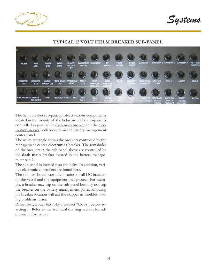
31
Systems
TYPICAL 12 VOLT HELM BREAKER SUB-PANEL
The helm breaker sub-panel protects various components located in the vicinity of the helm area. The sub-panel is controlled in part by the dash main breaker and the elec-tronics breaker both located on the battery management center panel. The white rectangle shows the breakers controlled by the management center electronics breaker. The remainder of the breakers in the sub-panel above are controlled by the dash main breaker located in the battery manage-ment panel.The sub panel is located near the helm. In addition, vari-ous electronic controllers are found here. The skipper should learn the location of all DC breakers on the vessel and the equipment they protect. For exam-ple, a breaker may trip on the sub-panel but may not trip the breaker on the battery management panel. Knowing his breaker location will aid the skipper in troubleshoot-ing problems faster. Remember, always fi nd why a breaker “blows” before re-setting it. Refer to the technical drawing section for ad-ditional information.

32
Chapter 4
TYPICAL 12 VOLT HELM BREAKER SUB PANEL DESCRIPTION
HORN- protects the air horn located on the hardtop.
PANEL LTS- protects the helm (dash) back-lit icons.
NAV LTS- protects the port and starboard deck naviga-tion for night cruising.
WINDSHIELD VENT- protects the fresh air wind-shield vents.
DECK LTS.- protects the deck light circuit.
UNDERWATER LTS.- protects the transom mounted light (under platform) circuit.
PORT WIPER- protects port windshield wiper circuit.
STBD. WIPER- protects the starboard windshield wip-er circuit.
SUNROOF (CONVERTIBLE HARDTOP)- pro-tects the motor that regulates the sunroof movement forward or aft.
COCKPIT LTS.- protects the cockpit installed light cir-cuit.
HARDTOP LTS.- protects the sunroof ceiling lights.
BILGE LTS.- protects the garage and engine room light circuitry.
FUEL XFER- protects the sump mounted transfer pump. COCKPIT 12 VOLT OUTLET- protects the accessory plug circuitry.
CAPTAIN SEAT UP/DOWN- protects the helm seat’s up/down movement circuitry.
CAPTAIN SEAT FWD/AFT- protects the helm seat’s forward and aft movement circuitry.
TV HATCH- protects the optional cockpit television overhead cabinet lid.
COCKPIT FRIDGE.- protects the cockpit refrigerator circuit.
TRIM TABS- protects the transom mounted electric-hydraulic trim tab circuit.
WINDLASS- protects the deck mounted foot petals.
COCKPIT STEREO- protects the dash stereo power circuit.
STEREO AMP- protects the stereo amplifi er.
PORT WINDOW WASHER- protects the motor cir-cuitry.
STBD. WINDOW WASHER- protects the motor cir-cuitry.
DE-FOG FAN- protects the windshield defogging sys-tem.
CO MONITOR- protects separately the 3 CO detectors located in the forward, salon and aft staterooms.
ACC. 1- protects the accessory equipment circuit.
ELECTRONICS- protects the dash electronics switch.
VHF- protects the marine radio circuitry.
COCKPIT DVD- protects the DVD player.
GAS VAPOR- not used since both vessels use diesel.

33
Systems
TYPICAL 12 VOLT HELM BREAKER SUB PANEL DESCRIPTION (CONTINUED)
PLOTTER 1- protects the GPS/Plotter starboard dash mounted circuitry.
PLOTTER 2- protects the GPS/Plotter port dash mounted circuitry.
RADAR- protects the deck mounted radar circuitry.
SEA KEY- not used.
SIRIUS WEATHER- protects the satellite weather cir-cuit.
CAMERA 1- protects a camera circuit.
CAMERA 2- protects a camera circuit.
CAMERA 3- Currently not used.

34
Chapter 4
TYPICAL DC (12 VOLT) WIRING COLOR CODE & SIZES
BLACK 16,14,12,10,8,6,4,2,2/0,40 GROUNDS
BLACK/WHITE 16 HALON INDICATOR
BLACK/YELLOW 10,16 GRD. DIESEL TRANSFER PUMP,MERC DIESEL STOP CIRCUIT
BLACK/WHITE 10 HALON MAIN GRD. FEED
BROWN/BLACK 10 MACERATOR, SUN ROOF
BROWN 10 SUN ROOF
BROWN 14 AFT BILGE PUMP-MANUAL
BROWN/WHITE 14 AFT BILGE PUMP-AUTO
BROWN/RED 14 FWD. BILGE PUMP-AUTO
BROWN/BLUE 14 FWD. BILGE PUMP-MANUAL
BROWN/PINK 16 CO DETECTOR
BROWN/BLACK 16 SHOWER SUMP PUMP
YELLOW 12,10 BLOWER
YELLOW/WHITE 16 HEAD VENT FAN MOTOR
YELLOW/BLACK 16 STEREO MEMORY
YELLOW/RED 14 ENGINE START CIRCUIT
Note: The list above applies to a number of vessels. Vessel components/wiring may vary depending on the model.

35
Systems
TYPICAL DC (12 VOLT) WIRING COLOR CODE & SIZES
ORANGE 10,12VACUUM TOILET, REFRIGERATOR,HATCH RAM
ORANGE 16 WIPER RUN
ORANGE/WHITE 16 WIPER PARK
ORANGE/BLACK 10,12,16 HORN, HATCH RAM
BLUE 14 INTERIOR LIGHTS, SWITCHED CIRCUIT
BLUE/RED 14 INTERIOR LIGHTS, CONSTANT HOT CIRCUIT
BLUE/BLACK 16 COCKPIT SOFT LIGHTS
BLUE/GREEN 16 INTERIOR SOFT LIGHTS
BLUE 10 CABIN LIGHT MAIN CIRCUIT FEED
GRAY 14 NAVIGATION LIGHTS, RUN-NING, BOW, TRANSOM LIGHTS
GRAY/BLACK 14 NAVIGATION LIGHTS, AFT AN-CHOR, MASTHEAD
GRAY/WHITE 14NAVIGATION LIGHTS, MAST-HEAD, FWD. RUNNING LIGHTS
RED 16
POSITIVE FEED- ELECTRON-ICS, GAS VAPOR DETECTOR, BREAKER TO DASH SWITCH FEEDS
Note: The list above applies to a number of vessels. Vessel components/wiring may vary depending on the model.

36
Chapter 4
TYPICAL DC (12 VOLT) WIRING COLOR CODE & SIZES
RED/WHITE 16 WINDLASS CONTROL-DOWN
RED/BLACK 16 WINDLASS CONTROL-UP
RED/WHITE 14 BATTERY PARALLEL-LOAD
RED 14 POSITIVE FEED-ELECTRONICS
RED 12 POSITIVE FEED-ELECTRONICS
RED 10 POSITIVE FEED-AUTO PILOT
RED/VIOLET 10 FUEL TANK TRANSFER PUMPAMPLIFIER POWER
RED 8 POSITIVE FEED- MAINALTERNATOR CHARGE
RED 6 POSITIVE FEED- MAINALTERNATOR CHARGE
RED 4 POSITIVE FEED-MAIN
RED 2 POSITIVE FEED- MAIN START-ER, BATTERY, GENERATOR
RED 2/0 POSITIVE FEED- MAIN, START-ER, BATTERY
PURPLE 16 STBD.IGNITION, HOUR METER-WINDSHIELD VENT
PURPLE/WHITE 16 PORT IGNITION, HOUR METER,WINDSHIELD VENT
PINK 16 STBD. FUEL TANK SENDER
PINK/BLACK 16 PORT FUEL TANK SENDER
TAN/BLUE 16 ENGINE ALARM CIRCUIT
GREEN 16 TANK LEVEL MONITOR, SPOT-LIGHT
GREEN 10 SPOTLIGHT
GREEN 8 BONDING
Note: The list above applies to a number of vessels. Vessel components/wiring may vary depending on the model.

37
Systems
(AC) ALTERNATING CURRENT-GENERAL INFORMATION
OVERVIEW
Alternating current sometimes called AC current is brought on board through the use of a dockside shore-power) cord, reel system or produced on board through the generator. Just as a residential home uses 120/240 volts to run various household appliances and equipment the same holds true on your yacht.With AC current electrons “cycle” in one direction a short distance and reverse themselves traveling in the op-posite direction. This is how AC became known as alter-nating current. The rate that the current reverses itself is referred to as frequency. In the United States the alternat-ing current frequency is 60 cycles per second. Overseas a 50 cycle frequency per second is standard. Component specifi cations must match the country’s frequency.
BASIC ELECTRICAL TERMS
Voltage is a measurement of the electrical potential that an electrical power source contains for doing some type of work for us. Think of it as electrical pressure. An example might be your yacht’s battery.
Amperage is a particular amount of electricity fl owing through some part of a circuit. Think of it as the rate of electrical fl ow through your yacht’s wiring.
Resistance is measured in ohms and inhibits the electrical fl ow through a circuit. An example would possibly be an incandescent light bulb. The resistance in the light bulb element allows it to glow and brighten the cabin along with giving off heat. It is important that you understand and respect the al-ternating current system used on board. Be sure to read and follow any danger, warning, or caution labels in reference to the yacht’s electrical system or individu-al equipment components. Most of all, use common sense!
Since several of the electrical components on select yacht have changed, earlier and the later systems of AC current will be presented. Included are drawings that describe the system components for both the earlier and later versions. You will be able to quickly tell which system is installed on your boat by visually spotting the components on the deck or in the bilge (sump) and by reviewing the system drawings. Used in both earlier and later systems the dockside cord is the basic component used to deliver up to 50 amps of electricity from the marina dock power box to the yacht
itself. Before plugging in the dockside power cord check to see that all yacht AC breakers are off. This includes the incoming as well as both the main and equipment breakers at the AC ship’s control panel.
See the AC panel illustration later in this chapter.When connecting the shore power cord be sure to twist the cord into the yacht inlet plug fi rst. The inlet plug is located on the aft deck. The cord installs one way only. Align the 2 pins with the 90 degree shape, (or use the imprinted arrows and detentes located on the stainless steel part of the inlet), insert the cord end straight
into the inlet plug and twist in a clockwise direction to lock in place. Screw the threaded sealing ring into the shore power inlet until tight. This protects the inlet and cord pins from moisture.
DOCKSIDE (SHORE POWER) CORD SYSTEM
MARINA PLUGIN END
YACHT INLETPLUG IN END
50 FT. 50 AMPCORD
YACHT INLET

38
Chapter 4
DANGER!PREVENT BODILY INJURY, DEATH OR FIRE!
NEVER USE EXTENSION CORDS OR IMPROVISED CORDS
IN SHORE POWER/MARINA INLETS. USE ONLY APPROVED MARINE
SHORE POWER CORDS MATCHING THE ORIGINAL
WIRE GAUGE AND AMPACITY .
Typical domestic dockside cords (sometimes called the shore power cord) usually contains four conductors;
White-neutral ungrounded conductor
Green-grounding conductor
Red-ungrounded conductor containing 120 volts
Black-ungrounded conductor containing 120 volts
Note: Select yachts with an earlier isolation transformer minus the cord reel option create a neutral connection at the output of the transformer to isolate the shore-side earth grounded power from the boat’s AC system. This system uses the 50 amp dockside cord but the neutral leg stops at the yacht’s shore power inlet.
Plug the power cord into the marina dock power box last. This reduces the possibility of a shock hazard. There may be several types of inlet plugs located at the marina dock power center. The 30 amp plug is much smaller looking and the 50 amp cord will not physically fi t it. Also, marina dock power centers normally have breakers that must be activated after installing the dockside cord. Make sure the dockside cord has enough slack to weather changing tides if applicable and at the same time does not come in contact with the water. Check with the marina dockmaster for more information on their shore power operation and requirements. Before attempting to disconnect the shore power cord turn off all equipment and main AC breakers on the ship’s control panel to prevent any component damage.When disconnecting the shore power cord fi rst turn the breaker to the “off ” position at the marina dock power center. Then remove the dockside cord from the marina outlet. Always remove the cord from the yacht’s power inlet last. Roll the cord neatly and store it in a dry environment.
DOCKSIDE CORD SYSTEM- CORD REEL OPTION
Select yachts feature a DC powered cord reel system for reeling in the dockside cord. The dockside cord is rated at 50 amps and is attached to a reel which releases the needed cord length when pulled out. The power cord is accessible from just above the aft platform. The reel is located in the aft bilge. The power cord retrieval is accomplished by pushing a switch which powers the 12 volt DC motor.The yacht end of the cord is directly
wired into the cord reel. Therefore, there is nothing to be plugged into the yacht.The marina end must be plugged into the marina dock power center using the same procedure as the standard dockside cord.Note: Some yacht systems offer an additional remote control for power cord usage. Refer to the vendor owner’s manual for information on remote control operation.
PREVENT SEVERE INJURY OR DEATH!ALTERNATING CURRENT (AC) CAN KILL YOU!
DISCONNECT ALL ELECTRICAL POWER SOURCES
BEFORE ATTEMPTING TO REPAIR OR REPLACE
ANY ELECTRICAL COMPONENTS.
WARNING!

39
Systems
The illustration above shows a typical transom layout with the optional cord reel system. Notice the cord reel switch for cord retrieval. Once the cord is inside the inlet be sure to close the cover to reduce the effects of any water intrusion.
POSSIBLE PROBLEMS/SOLUTIONS
1. After the dockside cord is hooked up to the yacht and the marina dock power cen-ter and the AC ship’s panel main breaker for shorepower 1 or 2 is activated no volt-age is shown on the main panel AC volt meter.
Check the breaker on the marina dock power center to ensure it is activated.
On earlier yachts check the triple pole single throw break-er located near the battery charger in the bilge.
On later yachts check the ELCI 3 pole single throw breaker/voltage sensing device. The “power” icon should show green. If a leakage fault exists a “red” icon will light indicating the breaker is “tripped”. Use the test button to reset the breaker.
2. The marina dock power center lacks a 50 amp plug.
Call the dockmaster or marina personnel. An adapter cord may be available. NEVER IMPROVISE ANY TYPE OF CORD OR POWER INLET CHANGES!Also, an adapter cord may be purchased that delivers twin 30 amp service and adapts to the 50 amp yacht dockside cord. Adapters can be found at retail boating outlets. 3. The cord reel switch fails to retrieve the dockside cord.
Check the cord reel breaker located on the battery man-agement panel.
TYPICAL BOAT TRANSOMTYPICAL BOAT TRANSOM
CORD REELCORD REELSWITCHSWITCHINLETINLET
50 AMP50 AMPDOCKSIDEDOCKSIDECORDCORD
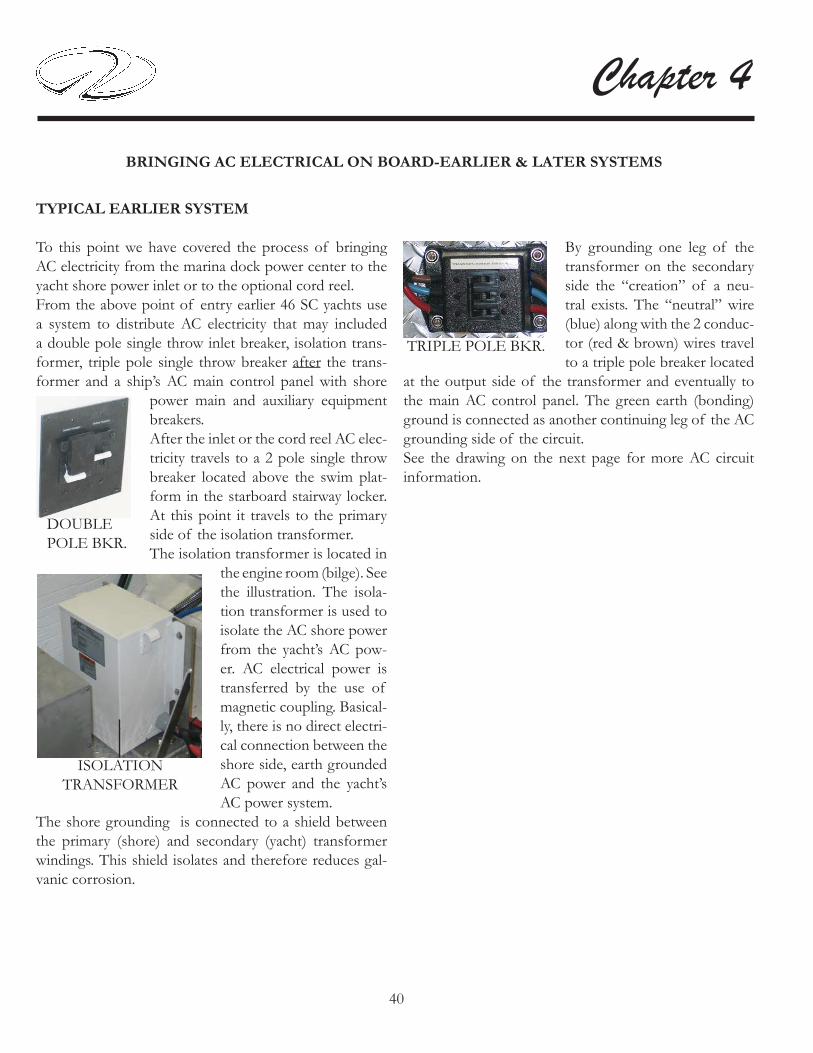
40
Chapter 4
BRINGING AC ELECTRICAL ON BOARD-EARLIER & LATER SYSTEMS
TYPICAL EARLIER SYSTEM
To this point we have covered the process of bringing AC electricity from the marina dock power center to the yacht shore power inlet or to the optional cord reel. From the above point of entry earlier 46 SC yachts use a system to distribute AC electricity that may included a double pole single throw inlet breaker, isolation trans-former, triple pole single throw breaker after the trans-former and a ship’s AC main control panel with shore
power main and auxiliary equipment breakers.After the inlet or the cord reel AC elec-tricity travels to a 2 pole single throw breaker located above the swim plat-form in the starboard stairway locker. At this point it travels to the primary side of the isolation transformer. The isolation transformer is located in
the engine room (bilge). See the illustration. The isola-tion transformer is used to isolate the AC shore power from the yacht’s AC pow-er. AC electrical power is transferred by the use of magnetic coupling. Basical-ly, there is no direct electri-cal connection between the shore side, earth grounded AC power and the yacht’s AC power system.
The shore grounding is connected to a shield between the primary (shore) and secondary (yacht) transformer windings. This shield isolates and therefore reduces gal-vanic corrosion.
ISOLATIONTRANSFORMER
By grounding one leg of the transformer on the secondary side the “creation” of a neu-tral exists. The “neutral” wire (blue) along with the 2 conduc-tor (red & brown) wires travel to a triple pole breaker located
at the output side of the transformer and eventually to the main AC control panel. The green earth (bonding) ground is connected as another continuing leg of the AC grounding side of the circuit. See the drawing on the next page for more AC circuit information.
TRIPLE POLE BKR.
DOUBLE POLE BKR.

41
Systems
TYPICAL EARLY YACHT AC CIRCUITRY FLOW CHART
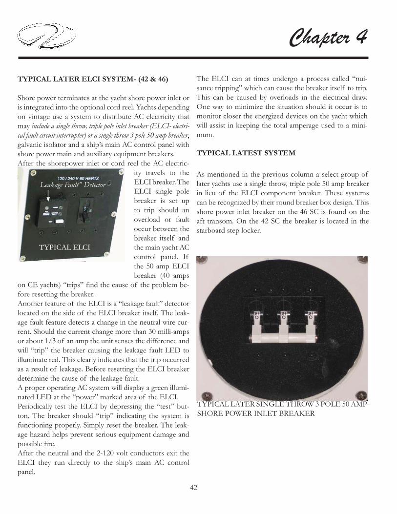
42
Chapter 4
TYPICAL LATER ELCI SYSTEM- (42 & 46)
Shore power terminates at the yacht shore power inlet or is integrated into the optional cord reel. Yachts depending on vintage use a system to distribute AC electricity that may include a single throw, triple pole inlet breaker (ELCI- electri-cal fault circuit interrupter) or a single throw 3 pole 50 amp breaker, galvanic isolator and a ship’s main AC control panel with shore power main and auxiliary equipment breakers.After the shorepower inlet or cord reel the AC electric-
ity travels to the ELCI breaker. The ELCI single pole breaker is set up to trip should an overload or fault occur between the breaker itself and the main yacht AC control panel. If the 50 amp ELCI breaker (40 amps
on CE yachts) “trips” fi nd the cause of the problem be-fore resetting the breaker. Another feature of the ELCI is a “leakage fault” detector located on the side of the ELCI breaker itself. The leak-age fault feature detects a change in the neutral wire cur-rent. Should the current change more than 30 milli-amps or about 1/3 of an amp the unit senses the difference and will “trip” the breaker causing the leakage fault LED to illuminate red. This clearly indicates that the trip occurred as a result of leakage. Before resetting the ELCI breaker determine the cause of the leakage fault.A proper operating AC system will display a green illumi-nated LED at the “power” marked area of the ELCI.Periodically test the ELCI by depressing the “test” but-ton. The breaker should “trip” indicating the system is functioning properly. Simply reset the breaker. The leak-age hazard helps prevent serious equipment damage and possible fi re.After the neutral and the 2-120 volt conductors exit the ELCI they run directly to the ship’s main AC control panel.
TYPICAL LATEST SYSTEM
The ELCI can at times undergo a process called “nui-sance tripping” which can cause the breaker itself to trip. This can be caused by overloads in the electrical draw. One way to minimize the situation should it occur is to monitor closer the energized devices on the yacht which will assist in keeping the total amperage used to a mini-mum.
As mentioned in the previous column a select group of later yachts use a single throw, triple pole 50 amp breaker in lieu of the ELCI component breaker. These systems can be recognized by their round breaker box design. This shore power inlet breaker on the 46 SC is found on the aft transom. On the 42 SC the breaker is located in the starboard step locker.
TYPICAL ELCITYPICAL ELCI
Leakage Fault” Detector
TYPICAL LATER SINGLE THROW 3 POLE 50 AMP-SHORE POWER INLET BREAKER

43
Systems
As part of the AC boat circuitry he green ground wire takes a different path. It exits the yacht shore power inlet or cord reel and travels to a galvanic isolator. See the il-lustration. A 60 amp (60 hertz) galvanic isolator for domestic use is connected in series with the AC grounding “green” wire.
Overseas yachts use a 30 amp (50 hertz) galvanic isolator. The purpose of the gal-vanic isolator is to isolate the yacht’s grounding sys-tem from the shorepower ground. The galvanic iso-
lator allows AC voltage to travel back to the green ground wire at the marina power center in the event a short ex-ists on the boat. Also, the isolator blocks any DC current from traveling on the green ground wire. This eliminates the possibility of galvanic interaction from other boats in the vicinity.The green ground or “bonding wire” runs from the yacht’s shore power inlet or optional cord reel to the gal-vanic isolator. From the output of the galvanic isolator it runs to the AC ground buss located behind the AC main control panel in the salon. Since the galvanic isolator is not polarized either termi-nal can be used for the inlet or output side for the green grounding wire. See the illustration.There is a fan located inside the isolator. If you ever hear the fan running the isolator has failed. Disconnect the shore power from the boat and check the system. Call your closest Regal yacht dealer for more information. Do not to store objects inside the locker that might in-hibit air fl ow to the galvanic isolator fan. Note that the galvanic isolator system is also used in yachts using the 50 amp main breaker (no ELCI). Nor-mally the galvanic isolator is found in the engine room sometimes called the bilge or sump.
TYPICAL GALVANIC ISOLATOR

44
Chapter 4
TYPICAL LATER AC ELCI CIRCUITRY FLOW CHART

45
Systems
TYPICAL MAIN AC PANEL METER/SWITCH FUNCTIONS
The typical main AC120/240 volt control panel is located at the starboard aft salon. Lift the overhead cabinet door to gain access to the panel. The main call outs on the panel will be addressed. This panel serves as the main dis-tribution for the incoming shore power from the marina power center or from the ship’s generator when at cruise. The ship’s main DC panel is located along side of the AC panel. Information on the DC panel is found earlier in this chapter.
SHOREPOWER PANEL DISTRIBUTION
As noted earlier the shore power cord delivers AC elec-tricity through the yacht’s shore power inlet or the op-tional cord reel system. The AC current travels through the vessel’s electrical system to the main AC 120/240 volt control panel. The AC electricity is now ready to be dis-tributed to the various equipment components.
Leg A Leg B
240 VoltsReversePolarityIndicators

46
Chapter 4
TYPICAL AC MAIN YACHT CONTROL PANEL
REVERSE POLARITY INDICATOR
Before activating the 50 amp main breaker visually check for a green light at the reverse polarity indicator. The green light indicates there is no reverse polarity. If the red light appears on the revese polarity indicator a hot wire and ground are probably reversed somewhere in the cir-cuit from the dock to the main panel. On ELCI equipped yachts the ELCI breaker will “trip” if a reversed polarity situation develops. On earlier isolation transformer yacht’s there is no ELCI breaker. On select later yachts the main 50 amp shore power inlet breaker will “trip”.In all cases do not activate the main 50 amp breaker. Take immediate corrective action to fi nd the cause of the re-verse polarity situation. At this point, disconnect the shorepower cord from the marina power center and call for professional assistance.
50 AMP MAIN BREAKER
This single throw, triple pole main breaker controls power to the 120 and 240 volt sections of the panel and eventu-ally delivers electricity through a system of sub breakers to the entire yacht. Before you energize the breaker it is always a good idea to check all the legs on both the 120 volt and 240 volt side for breakers that are in the “on” po-sition. Turn any breakers found “on” to the “off ” posi-tion. This prevents any excessive equipment motor draws and may eliminate any system arcing.With the reverse polarity indicator showing the green icon, activate the main breaker by pushing the single throw arm up. AC electricity now is distributed to both the 120 and 240 volt legs of the panel. Turn on sub breakers as needed always being conscious of the load current meters..
60 AMP AC GENERATOR BREAKER
When the yacht is under generator power at sea AC elec-tricity is distributed through the 60 amp main generator breaker located on the AC main ship’s panel beside the main breaker. See the previous illustration and the genera-tor section for further information.
Before activating the generator AC breaker it is recom-mended to make sure all the equipment breakers are “off.” Slide the bar to the left so the generator 60 amp breaker arm will clear when activated. Push the single throw arm up to energize generator AC current to the sub panel breakers. Switch on the sub panel breakers as needed.
LINE VOLTAGE/CURRENT METERS
After the shore power 50 amp main breaker or generator 60 amp breaker is activated line voltage up to 240 volts will display on the 240 volt (right side) of the main panel. As sub panel 240 volt equipment breakers are activated the load current meter (extreme right side of 240 volt panel) will show an amperage draw. Normally the amper-age will ascend as more equipment breakers are activated and will descend as equipment breakers are deactivated.After the 60 amp main panel breaker or generator breaker has been activated no voltage will appear on the 120 line voltage meter at the extreme left side of the main control panel with the 120 shore power switch in the “off or cen-ter” position. This is normal. See the illustration.The 120 volt shore power switch is located between the line voltage and load current meters. See the illustration.As stated above with the shore power switch in the “cen-ter” position it is off. When the shore power switch is moved to the left the line voltage meter will display up to 120 volts available at leg A. As equipment breakers are activated the load current (amperage) meter will ascend and descend as equipment breakers are deactivated.When the shore power switch is moved to the right the line voltage meter will display up to 120 volts available at leg B. As equipment breakers are activated the load cur-rent (amperage) meter will ascend and descend as equip-ment breakers are deactivated.As a general note on equipment breakers when leaving the yacht it is recommended that most breakers be turned off. It may be necessary to leave the battery charger on dur-ing extended periods and the salon refrigerator. Since the refrigerator is dual voltage (12 and 120) make sure the DC refrigerator breaker is activated and the AC refrigerator breaker is deactivated upon leaving the vessel.

47
Systems
Leg A
Fwd. Outlets- This 15 amp breaker controls the 120 volt GFCI and outlets downstream.
Ice Maker- This 15 amp breaker controls the cockpit ice-maker unit.
Microwave- This 15 amp breaker controls the galley overhead microwave.
Entertainment- This 30 amp breaker controls the salon (main stateroom) entertainment center.
Stove- This 20 amp breaker controls the galley stove.
Water Heater- This 15 amp breaker controls the water heater located in the engine room (bilge). Never turn on this breaker without water in the system as the water heater element will be damaged and replacement will be needed.
120 VOLT MAIN PANEL BREAKER DESCRIPTION (TYPICAL)
Leg B
Aft Outlets- This 15 amp breaker controls the 120 volt GFCI and outlets downstream.
Refrigerator- This 15 amp breaker controls the galley refrigerator. This unit is dual voltage which means it can run on 120 volts AC or 12 volts DC electricity. See the note on the previous page regarding leaving the yacht with the refrigerator in the operational mode.
Washer/Dryer- This 15 amp breaker controls both the stackable washer and dryer units located in the master stateroom armoire.
Cockpit Grill- This 20 amp breaker controls the electric grill.
Acc- This 15 amp breaker provides for additional after-market components.
Acc- This 20 amp breaker provides for additional after-market components.

48
Chapter 4240 VOLT MAIN PANEL BREAKER DESCRIPTION (TYPICAL)
Battery Charger- This 30 amp breaker controls the bat-tery charger located in the engine room (bilge). It is rec-ommended that when leaving the yacht for extended pe-riods this breaker be left energized in order to keep the ship’s batteries in a charged condition.
Fwd. Air Cond- This 30 amp breaker controls the for-ward air conditioning unit.
Aft Air Cond- This 30 amp breaker controls the air con-ditioning unit.
A/C Pump- This 15 amp breaker controls the air con-ditioning pump located in the engine room (bilge). This pump supplies water to the forward air conditioning unit and the aft air conditioning unit along with the “cool cockpit” unit if installed.
Cool Cockpit- This 30 amp breaker controls the air con-ditioning unit.
Note: Some of the listed equipment may be optional.
TYPICAL AC WIRE USAGEGAUGE FUNCTION
6/4 Romex Boat Cable Generator Output
6/4 Romex Boat Cable 50 Amp Service
10/3 Romex Boat Cable 30 Amp Service
10/3 Romex Boat Cable A/C Main Power Supply
10/3 Romex Boat Cable Stove Power Supply
14/3 Romex Boat Cable A/C Pump, Power Pump Relay
14/3 Romex Boat Cable Receptacles, Microwave, Water Heater, Refrigera-tor, Ice maker, Central Vacuum System
TO PREVENT POSSIBLE ELECTRICAL SYSTEM DAMAGE OR FIRE DO NOT TRY TO ACTIVATE
SHORE POWER MAIN BREAKERS IF REVERSE POLARITY LIGHT IS
DISPLAYED.
WARNING!
240 Volt Leg

49
Systems
GFCI Outlet
Sometimes current in a circuit escapes its normal route and fi nds a “ground fault”. If that vehicle ends up to be your body and the current passes through your heart the results could be deadly. A ground fault interrupter or GFCI senses the difference between the hot and neutral wire current before a fatal dose can be conducted and in a fraction of a second cuts the current. The GFCI devices used in homes are normally not ignition protected. All of the Regal yacht’s GFCI’s are ignition protected. Your yacht uses 120 volt receptacles. By using a GFCI as the fi rst receptacle in the circuit all the receptacles down stream on the same circuit are protected by the initial GFCI. This is accomplished by attaching the hot wire to the line terminal of the GFCI receptacle and the out-going hot wire to the load terminal. The neutral wires also use line and load terminals on the opposite side of the GFCI receptacle. You can identify the GFCI primary receptacle by the test and reset breaker in the center of the device. Check the GFCI protection monthly. If a problem develops with the GFCI circuitry call a marine electrician to access the situation. The GFCI outlets are especially useful when electrical equipment is employed such as a drill or in the bathroom with the use of personal devices such as curlers and hair dryers. Never use any electrical devices when puddling water is present to prevent a possible shock hazard.
TESTMONTHLY
TYPICALGFCI
TESTRESET
GFCI’S (GROUND FAULT CIRCUIT INTERRUPTER
The GFCI is pro-gramed to protect a person from line to ground shock hazards which could occur from various electrical devices operating off of the device or recep-tacles down stream.It does not prevent line to ground electric shock, but does cut down the exposure time to a fraction of a second before the de-vice trips. It does not protect people against
line to line or line to neutral faults. Also, it does not pro-tect against short circuits or overloads; this is the circuit breakers job. All GFCI’s should be tested monthly to make sure they and the receptacles they protect “down stream” are pro-tecting against ground-faults.

50
Chapter 4
Ignition Protected Devices
Many electrical devices in everyday use tend to “arc” or spark when being used. These include motors, fans, switches, relays, etc. Boats in general use many of these same devices but they are protected from any sparking that may cause the device to ignite with any vapors that are typically found in the engine room and/or fuel tank compartments. Obviously, gasoline powered vessels contain a much higher risk of explosion over diesel powered vessels but diesel under the right circumstances can ignite and burn. Still when replacing any electrical device especially in the bilge or engine room make sure it is ignition protected. This means it has been tested and normally the device is stamped with a marking making it safe to use. Most automotive type devices are not ignition protected especially engine starters and alternators.
Note smaller hose barb for generator feed and return.
POSSIBLE PROBLEMS/SOLUTIONS (GFCI’S)
1. If the “reset” button does not pop out, the GFCI is probably defective and should be replaced. 2. If the “reset” button pops out one time but tends to stick the next the GFCI should be replaced.
3. The GFCI “reset” button pops out when something is turned on. This may indicate an internal wiring prob-lem with the GFCI or there may be a ground-fault down stream.4. The GFCI “reset” button is in the pressed position and nothing works. Check the appropriate breaker at the main ship’s AC control panel to make sure it has not “tripped” or as been deactivated.
Also, GFCI down stream recep-tacles can be tested with a plug-in type GFCI tester. This tester con-tains a GFCI test buton which ac-complishes the same thing as the GFCI receptacle built-in test but-ton. This tester can be purchased at electrical supply houses or marine retailers.
To test a GFCI on your yacht fi nd a 120 volt night light or small lamp to plug into the GFCI outlet. Try it in another circuit fi rst to make sure it lights.After the lamp is plugged into the GFCI outlet the lamp should light. Now press the “test” button at the GFCI receptacle center. The GFCI’s “reset” button should pop out and the lamp should go out. This means the GFCI itself is functioning properly. Press the “reset” button to restore power to the outlet. Test each GFCI circuit monthly.You can use the lamp to check receptacles down stream from the GFCI. All receptacles should light the lamp and should go out when the “test” button is pressed.
Testing GFCI’S

51
Systems
TYPICAL AC GENERATOR (GEN-SET)
OVERVIEW
The diesel generator (gen-set) is used to provide on board alternating current (AC) when the vessel is unplugged from the dockside cord. Generator frequency known as hertz is domestically set at 60 while overseas countries normally require a setting of 50. As the generator reaches full rated no load output (amps) at 60 hertz it should display 120 volts. At 50 hertz it should display 230 volts. The generator is located in the port engine room. Some basic system components are identifi ed below. MUFFLER SOUND ENCLOSURE
TYPICAL GENERATORFEED
FUEL FILTERFUEL FILTER
PORT 46SC FUEL TANK SHOWN
Typical Generator Fuel System
The generator is supplied by the same fuel tanks as the engines. The generator fuel and return valve are normally marked for identifi cation purposes. The feed valve features off and on positions. “Off ” position is 90 degrees perpendicular to the valve. “On” position is in line with the valve as shown above. The return generator valve is located on the forward top of the port fuel tank. Familiarize yourself with the location of all equipment and valves. Note: Normally the generator feed and return use a 3/8 inch barb located on the fuel tank.The fuel system features an in-line remote fuel fi lter located below the generator. It’s job is to keep fi ne particles and water out of the generator fuel injection system. Refer to the vendor information for periodic maintenance schedules. Clean fuel is the life line of diesel engine performance.
The generator features a sound enclosure which reduces noise and enables quick access for most inspections, troubleshooting and routine maintenance.

52
Chapter 4
Changing Element
The element due to contaminated fuel needs to be changed periodically. Be sure to close the generator fuel tank valve located under the master state room berth before changing the element since the fuel tank is higher than the fuel fi lter. Signs of necessary element replacement may be power loss, hard starting or large levels of contaminants/water in the element collection bowl when drained.To replace the element fi rst remove the old one by turning it in a counterclockwise direction by hand. Be sure to have a pan in place to catch any dripping fuel. Coat the new element and O ring with fresh diesel fuel and then thread the element clockwise by hand until snug. Do not use any tools.Loosen the vent plug. Turn the primer valve counterclockwise until fully open. Turn on the generator fuel tank valve located under the master state room berth. Hand operate the primer valve up and down until the element is full as seen by fuel purging at the drain plug. Bleed the system as needed. Close the vent plug snugly. Close the primer valve by turning the valve clockwise until tight. Start the engine and check for fuel or air leaks.
Bleeding System
Periodically air may need to be bled from the generator fuel system. Basically as stated above loosen vent plug and the hand operated fuel primer valve. Pump the primer until a solid stream of fuel comes out of the plug verses some fuel and some air bubbles. Tighten all components until snug.
Draining Collection Bowl
Since water is heavier than fuel it will settle in the collection bowl at the bottom of the element. The vendor recommends inspecting/draining the collection bowl daily. To check/drain the element loosen the drain plug on the bottom of the collection bowl. Use an environmentally safe container to catch any contaminated fuel. Dispose of according to local, or state regulations. Close the drain snugly when fi nished to prevent any fuel leakage.Note: Water in diesel fuel will gather at the bottom of a container since it is heavier than diesel fuel and will appear as a different color and consistency.
INLET
OUTLET
VENT PLUG
DRAINPLUG
FUEL PRIMING VALVE
TYPICAL GENERATOR FUEL FILTER

53
Systems
REMOTE INSTRUMENTPANEL
AC BREAKER
GEN-SETENGINEBREAKER
TYPICAL GEN-SET SWITCH CLUSTER- MAIN PANEL
Note the illustrations showing the remote instrument and start panel. As part of the generator electrical system an 8 amp fuse protects the remote instrument panel wiring circuit. See illustration B.Above the fuse is a switch. This switch must be in the “run” position or the generator will not start. The emer-gency stop switch shuts the fuel off to both the remote and ship’s main control panel and is normally for mainte-nance purposes. See illustration B.A 20 amp DC manual reset breaker protects excessive cur-rent draw or electrical overload anywhere in the generator engine wiring. Should this breaker trip the generator will shut down. Reset the breaker only after the cause of the problem has been determined. See illustration A. An AC breaker will automatically disconnect any genera-tor AC power from reaching the main ship’s control panel in case of an electrical overload. It can be manually shut off when performing generator maintenance to ensure no AC power is coming out of the generator. See illustra-tion A.
ILLUSTRATION A
Typical Electrical System
The generator starting system uses the port cranking battery. The generator is normally started at the 12 volt ship’s control panel located in the salon but it can also be started using the remote instrument panel located at the generator itself as needed. The latter is especially useful while maintenance is being conducted. The generator remote instrument panel features temperature, oil, DC volts, hour meter gauges and pre-heat, start and stop switches. The starting switches can be reached through an access panel at the sound shield. One of the switches is set up different on the ship’s main control panel. Here the pre-heat switch is called an “on” switch. The start and stop switches by name and function are identical to the switches on the remote panel.
INST. PANEL FUSE
EMERGENCY STOP
RUN
ILLUSTRATION B
NOTICETO PREVENT POSSIBLE GENERATOR
DAMAGE ALL SHORE POWER BREAKERS AND AC SWITCHES
NEED TO BE DEACTIVATED BEFORE STARTING OR STOPPING GENERATOR.

54
Chapter 4
Typical Exhaust System
The diesel generator exhaust system features a dual tier operation. As the water and exhaust exit the generator they travel to the muffl er. The muffl er discharges the heavier water out the muffl er bottom and through the hull. The exhaust itself is exited out the muffl er top and through the hull. The benefi ts of the system are two-fold. First, the actual decibel or sound level is decreased. In addition, the lower resonating sound is more pleasing to the ear. For colder climates, a drain plug is installed in the muffl er.
Before departure always check the hose connections for signs of water and air leaks. Tighten hose clamps as needed.
GEN-SET OUTLET
TYPICAL GENERATOR MUFFLER
EXHAUSTDISCHARGE
WATERDISCHARGE
PORT TRANSOM
Turn generator seacock off. Check strainer for debris. Turn generator seacock on before starting generator.
Ensure that all main panel and equipment breakers are off.
Inspect the generator for fuel, oil, exhaust or water leaks.
Check generator engine oil level. Top off with correct viscosity as required.
Check coolant for proper level at recovery tank. Add as needed.
Check the main fuel tank to ensure there is adequate diesel for both the generator and the engines. Apply the one-third rule.
Check for loose wires at the alternator.
Check the port side cranking battery (weekly).
Check drive belts for wear and proper tension (weekly).
Record the hour meter reading to meet maintenance scheduling.
Before Starting Generator
The following items should be checked each time before starting the generator. This covers the basic system components.

55
Systems
Starting Generator
The following generator starting information is specifi ed for use at the ship’s main control panel located in the salon. It also assumes that the checklist on
the last page has been completed and all system components are in good condition. For further information, contact your closest Regal yacht dealer or refer to the generator operation manual.
1. Turn “on” the generator seacock in the engine room.
2. Check the ship’s main control panel to ensure shore main and all equipment breakers are deactivated.
3. At the ship’s main control panel fi nd the generator switch cluster. Push down on the “on” switch and hold approximately 4 to 5 seconds. This provides a preheat cycle for the generator.
4. While holding the “on” switch down push down on the “start” switch. This will engage the generator starter to crank over the gen-set engine.
5. Once the generator starts, release both the “on” and “start” switches.
6. Let the generator run without a load for several minutes.
6. At the ship’s main control panel slide the transfer bar completely to the left. This will permit the 60 amp AC generator breaker to be activated. To activate the breaker fl ip it up. At this point AC voltage should display on the AC line voltage meter.
7. At this point activate the desired AC equipment breakers.
Stopping Generator
To stop the generator follow these steps at the ship’s main control panel.
1. Turn to the “off ” position all AC equipment breakers.
2. Turn to the “off ” position the 60 amp AC generator breaker. At this point, no AC line voltage will be displayed at the AC volt meter. Let the generator run for 3-5 minutes without a load to cool down.
3. Stop the generator by pressing down the “stop” switch at the main panel generator switch cluster. Hold it down until the generator stops running.
4. If desired plug in the appropriate dockside cord. Slide the transfer bar completely to the right. Flip up the shore main 60 amp breaker for dockside power. AC voltage should display on the AC line voltage meter.
POSSIBLE PROBLEMS/SOLUTIONS
1. With generator main control panel ac-tivated there is no voltage at the AC line voltage meter. Check AC output breaker on the generator. It may of tripped due to an overload.
2. The generator quit do to overheating. Check the gen-erator strainer for obstructions such as seaweed, plastic, or shellfi sh. Be sure to turn off seacock before removing the strainer basket.
3. The generator will not start from the main ship’s panel after being serviced. Make sure the generator mounted switch is in the “run” position.
4. The generator will not crank over to start. Check the port cranking battery by starting the port engine. If it starts battery is up. Then check all generator battery con-nections. Tighten any loose connections.

56
Chapter 4
TYPICAL AIR CONDITIONING SYSTEM
Overview
The current air conditioning dual zone system features a total output of 32,000 BTU’s (British Thermal Units). The system utilizes a single 230 volt pump which delivers cooler seawater to both evaporators/condensers found under the main cabin/salon fl oor. Warmer seawater exits the yacht through a manifold and various thru-hull fi ttings.The port evaporator/condenser unit is connected to the aft air conditioning system. The starboard evaporator/condenser unit is connected to the forward air conditioning system. Each of the evaporator/condenser units incorporate a compressor to compact the R-22 refrigerant.The forward air conditioner serves the forward cabin, forward head, and starboard salon.The aft air conditioner serves the port main cabin, galley, aft master stateroom and aft head.The Elite control panel (thermostat) for the forward air conditioning system is located in the main cabin (salon). The Elite control panel for the aft air conditioning system is located in the aft master stateroom.
Optional “cool cockpit” air conditioning is currently featured at 27,000 BTU’s. The compressor unit is lo-cated in the starboard en-gine room. Seawater is de-livered through a single 230
volt pump located in the engine room. The Elite control panel for the optional cool cockpit op-tion is located normally at the refreshment center.
TYPICALAIR CONDITIONING EVAPORATOR/CONDENSER UNIT
TYPICAL A/C PUMP

57
Systems
Reverse Heat
Your yacht air conditioning system features a reverse heat cycle. This can be extremely valuable to boater’s in colder climates especially for early spring and late fall cruising. To accomplish reverse cycle heating, the R-22 refrigerant flows in the opposite direction through a reversing valve located on the evaporator/condenser unit. Heat is transferred from the seawater in the coil of the condenser to the R-22 refrigerant and then to the air as it is blown through the evaporator to the cabin. Obviously, the temperature of the seawater will effect the air conditioner effi ciency.
The temperature variance for cooling effi ciency is:
Up to 90 Degrees F. ( 32.2 Degrees C. )
The temperature variance for heating effi ciency is:
Down to 40 Degrees F. ( 4.4 Degrees C. )
Typical Air Conditioning System Operation
Below is a basic quick start-up checklist for the air conditioning system. For more in depth information, refer to the vendor operation manual found in the owner’s documentation folder located in the port aft set of drawers in the aft master stateroom cabinet.
Operations Quick Start-Up Checklist:
1. Check the AC seawater strainer for debris.
2. Make sure the AC seawater pump seacock located in the engine room is opened completely (handle should be in-line with the hose).
3. Depending which air conditioning unit you desire to use (forward, aft, cockpit) activate that breaker on the yacht’s main AC control panel located in the starboard aft salon overhead cabinet.
4. Activate the air conditioner pump breaker located at the ship’s main AC control panel.
5. Check the port hull side for a steady stream of seawater. Seeing water here is normal when the forward/aft AC pumps are running. See illustration. If stream is diminished or no water emits from the fi tting immediately turn the AC pump off and investigate the cause of the problem. If optional cockpit air is installed check the starboard transom thru-hull fi ttings for a steady water stream.
5. Press the Elite thermostat Power button once to activate the air conditioning system. A blank screen displays when system is off and indicates present cabin temperature.6. For cooling or heating press and release the Mode button until the desired LED is illuminated ie; automatic mode.
7. Press the Up or Down button to set the desired cabin temperature. To view the set point, momentarily press and release the Up or Down button.
8. Auto fan LED lights when Auto fan speed is selected.

58
Chapter 4
TYPICAL ELITE AC CONTROL DIAGRAM
Note: The Elite display continually monitors the system components. Should a problem develop it sends a diagnostic code to the control (thermostaat) display. Refer to the vendor air conditioning manual (troubleshooting) to assist in identifying the problem.

59
Systems
PREVENT SEVERE INJURY OR DEATH!DISCONNECT
ALL ELECTRICAL POWER SOURCES BEFORE ATTEMPTING
TO OPEN, REPAIR OR REPLACE ANY AIR CONDITIONING COMPONENTS.
WARNING!
TYPICAL A/C INSPECTION TIPS
Seawater Strainer
The air conditioner seawater strainer locat-ed in the engine room should be cleaned pe-riodically of debris which can inhibit or stop the fresh seawa-ter supply. Always turn the sea-cock to the off posi-tion (90 degrees to the hose fitting) before cleaning a seawater
strainer. Remove the basket by turning the plastic cap in a counterclockwise direction. Set the cap and the O ring aside. Pull the basket from the unit, rinse with water, air dry and reinstall. Sediment at the bottom can be removed by just turning the plug in a counterclockwise direction. Set the plug and O ring aside. Place a container under the strainer to catch the sediment. Coat the O rings with waterproof grease containing a silicone or tefl on base. Reinstall O rings along with the plug and plastic cap. Turn on the seacock and check for leaks.
Return Air Filters
Once a month check the return air fi lter located on the face of each evaporator. To clean rinse with fresh water, air dry and reinstall.
TYPICAL A/C SEAWATERSTRAINER
BASKET
PLASTICCAP
PLUG
Drain Pans
As noted on an earlier page the AC evaporator/condenser units feature a 2” deep drain pan connected by a hose that runs to a sump pump and eventually exits overboard. Periodically just like your home AC, the pan needs to be rinsed clean of debris and possible mold.You can use a purchased product made specifi cally for cleaning AC units. Disconnect the outlet hose from the AC pan and install a made up hose (5/8” ) that will catch the used solution to fi ll a small container. Dispose of the container in accordance with federal, state and local regu-lations. Pour the solution into the pan and allow time for it to drain. Reconnect the original drain pan hose when fi nished.
Condenser Coil Cleaning
Periodically the condenser coils are recommended to be cleaned. This procedure should be done by a professional since an acid solution must be used.
POSSIBLE PROBLEMS/SOLUTIONS (A/C )
1. No or little water is noticed at the thru-hull fi ttings and a HPF shows on the dis-play which means the high pressure switch is open.The strainer or intake hose may be clogged, seacock may be closed or a hose
may be collapsed or kinked. Check AC pump breaker to verify pump operation.
2. Air conditioner will not start. Ensure the proper AC breaker is actuated on the ship’s main control panel.
3. No cooling or heating. Lower or raise set point on ther-mostat control to offset set point being satisfi ed. Check for obstructed seawater fl ow. Remove discharge side of pump hose to purge air (air-lock). Seawater temperature too high for cooling and too low for heating.
4. Fan coil is iced. Raise or lower control set point. Clean return air fi lter. Switch AC to heat until ice melts or as a last resort use a hair dryer to melt ice as needed.

60
Chapter 4
TYPICAL FRESH WATER SYSTEM Overview
Your vessel is equipped with a fresh water supply system. It consists of a fresh water tank, deck fi ll/vent fi ttings, monitor panel, pressure water pump with fi lter, distribution system, manifolds, wash down spigots and hot water heater. As needed the pressure demand type pump is energized, or the dockside system distributes water through the vessel.
The system is normally winterized from the factory utilizing a product called “Freeze Ban”. It is best to completely drain the Freeze Ban before adding any water to the tank in order to minimize the taste of Freeze Ban. Freeze Ban will not harm you but it does have a peculiar taste. The system requires little maintenance except occasional fl ushing of the tank, cleaning of the water fi lter and winterizing in cold weather climates.For more specifi c information on the water system contact your closest Regal yacht dealer.
Filling Water Tank At the Deck Fill
The fresh water system uses a tank to distribute water on board also known as potable water.
There is a water fi ll located on the forward deck along with a vent fitting used to evacuate any air from the tank as it is being replaced during the fi lling process. Make sure you do not mistake the water fi ll cap for waste or diesel. To fi ll the system turn the water fill cap counterclockwise.
Remove the cap and insert the supply hose. Make sure the water source is pure and drinkable. Fill until you see water emerging from the deck vent.Reinstall the fi ll cap and use the designed “key” to tighten it. If you do not have a key a quarter coin will work well.
TYPICAL WATERTYPICAL WATERTANKTANK
46 SC DECK FILL
Periodically check the water fi ll cap for tight-ness. On the underside of the water fi ll cap is an “O ring” which aids the water fi ll cap to seal prop-erly. The “O ring” should fi t tightly around the cap. If it is loose, cracked or damaged replace it since it
helps to keep debris out ot the water system.For general knowledge all red water lines carry the “hot” water on board your vessel. Likewise, all blue water lines carry the “cold” water.
Note: To completely turn vessel water off on 42’s and 46’s:
1. At mooring with the standard dockside water inlet valve connected turn the marina faucet off. Disconnect the dockside water inlet hose.
2. At sea deactivate the pressure water system breaker at the main ship’s electrical panel located in the salon.

61
Systems
Using Fresh Water (Potable) System
1. Fill the fresh water tank(s) until water is seen at the deck water fi ll vent.
2. At the ship’s main service panel activate the fresh water pressure pump system breaker. This will energize the fresh water pressure pump to send fresh water from the potable water tank through the cold water lines terminating at the various faucets and related components.
3. Open a faucet. Water pressure should be present. Opening each faucet for a few seconds will purge any air in the system especially in cases where the fresh water tank has run out of water. When water is running at a particular faucet it is not unusual to hear the water pump activate as it is trying to build up the pressure required in the system. Soon after the faucet is turned off the fresh water pump sound will end indicating the fresh water system is now up to specifi ed system pressure. Note: If the fresh water pressure pump continues to run long after the faucets are deactivated check for fresh water system leaks.
Note: Related to the above periodically check the fresh water monitor for fresh water tank levels. Do not run pressure water pump with system dry as water pump component damage will occur.
PREVENT PROPERTY DAMAGE!DISCONNECT
THE DOCKSIDE WATER INLET HOSE BEFORE LEAVING THE VESSEL.
WARNING!
TYPICAL AFT FRESH WATER PUMP
FRESH WATERPRESSUREPUMP
FRESH WATERSTRAINER/BASKET
Fresh Water Pressure Pump
In theory the fresh water pump system provides water pressure when dockside water is not available or used. Once energized the pump is automatic. It will shut down once system pressure has built up and will automatically start after a faucet is opened. The fresh water pressure pump features a removable strainer basket fi lter which collects any debris which has entered the fresh water system. The clear strainer cover highlights any debris.To clean the basket make sure the pressure water pump is off at the ship’s DC control panel. Unscrew the clear cover to access the strainer basket. Remove the strainer basket, clean, rinse with fresh water and reinstall basket and cover. Do not overtighten or use tools. Turn on the pressure pump breaker and check for leaks.
Note: It is recommended that the fresh water pressure pump breaker be fl ipped to the “off ” position when leaving your yacht to help prevent damage should a leak develop in the hot or cold water system.

62
Chapter 4
Operating Typical Standard Dockside Water System
Operating Optional Electric Hose Reel System
Optional hose reel system permits dockside marina (city) water to be used while the vessel is moored eliminating the need to use the on board potable water system. The system features the ability to return hoses both dockside and wash down back into the reel electrically through a motor and retrieval switch system.
Follow these steps to activate the system:
1. Verify that the water supply is safe and pure.
2. The dockside water inlet hose is located at the transom on the 46. On the 42 it is located in the port transom walk-through step locker. See illustration. Unscrew the protective cap on the dockside inlet hose and pull the length of hose needed to reach the dockside (marina) water supply and connect to the marina faucet.
3. Open the marina water supply spigot (faucet) which at this point will distribute dockside water to the yacht.
4.. Open onboard faucets as needed to help eliminate any air in the lines.
5. When disconnecting use the switch to retrieve dockside hose.
At Mooring-Using Standard Dockside Water Inlet
Yachts without the optional electric hose water reel system should perform the following steps to use dockside water.
1. Verify that the dockside water is pure and safe to use.
2. Locate the dockside inlet valve. Unscrew the cap. Connect a clean hose to the yacht’s dockside water inlet fi tting and the marina dockside water supply. A 50 foot white hose (safe for carrying drinking water)should reach most dockside faucets. Note: The dockside water inlet valve uses a system in-line valve that keeps the water traveling in one direction only.
3. Open the marina water supply faucet (spigot) which at this point will distribute dockside water to the yacht.
4. It may be helpful to open an on board faucet to help eliminate any air in the lines. Note that the pressure pump system is not activated using the dockside water inlet system.
TYPICAL DOCKSIDE WATER INLETVESSELS WITHOUT WATER HOSE REEL
SYSTEM
WASHDOWN FAUCET
42SC SHOWN
At Sea-Using Fresh Water Pressure Pump System
1. Energize the fresh water pump breaker at the ship’s main DC panel. This will permit water to fl ow to the appropriate faucet or component.Note: Remember that all fresh water at sea is being delivered through the on board potable water tank.Therefore, it is important to periodically check the fresh water monitor for remaining on board quanities.

63
Systems
WASHDOWNHOSE
WASH DOWNVALVE
HOSERETRIEVAL SWITCHES
Typical Transom Wash Down Hose Reel
WASHDOWNHOSEREEL
WASH DOWNHOSEREEL
46SC SHOWNDOCKSIDEHOSE
42SC SHOWN
46SC SHOWN
WASH DOWNVALVE
Typical Deck Wash Down Hose Reel
HOSERETRIEVAL SWITCH
FAUCET
PROTECTEDNOZZLE 42SC SHOWN
WASHDOWNHOSE
HOSERETRIEVAL SWITCH
PREVENT PROPERTY DAMAGE!DEACTIVATE THE FRESH WATER PRESSURE PUMP BREAKER AND
DOCKSIDE WATER INLET HOSE BEFORE LEAVING THE VESSEL.
WARNING!
On vessels with the dockside hose reel system a wash down hose reel is provided at the bow and transom. To use the wash down system:
1. With dockside water system is connected turn the wash down valve to the “on” position. Notice the illustrations highlighting the valves for both vessels.
2. To use the wash down bow system pull out required hose length and activate the faucet to control pressure.
3. To use the transom wash down activate hose nozzle.
4. Reel in hose and turn wash down valve off.
Note: To use the wash down system at sea make sure the wash down valve is open and the pressure water pump breaker at the main ship’s DC panel is in “on” position.
PROTECTEDNOZZLE

64
Chapter 4
Sanitizing Water System
If the vessel has been in an extended storage condition or you suspect the water system may be contaminated, then the system should be sanitized. You can purchase a water treatment kit with ingredients that will sanitize the system. Follow the directions with the treatment kit. If a water treatment kit is not available follow these steps to sanitize the water system.
1. Make sure the water tank is pumped until empty. Shut off the water pressure breaker at the 12 volt ship’s panel.
2. You will need approximately one gallon of a reduced bleach solution per each 15 gallons of tank capacity.
3. Formulate the correct amount of reduced bleach solution by mixing 1/4 cup of unscented household chlorine bleach per gallon of water. Press the monitor panel water tank switch at the ship’s control panel to determine the approximate number of gallons left in the water tank.
4. Pour the weakened bleach solution into the water tank. Again, use the formula of 1 gallon reduced bleach solution for every 15 gallons of tank capacity.
5. To further reduce the power of the bleach solution fi ll the remainder of the water tank with fresh, clean water.
6. At the ship’s 12 volt control panel, “fl ip” the water pressure breaker to the “on” position. Turn on the faucets to purge any system air and to circulate the bleach solution to all areas. Now turn off the water pressure breaker.
7. Let the solution set in the system for 3-4 hours.
8. Pump the water tank until empty.
9. Fill the water tank full with fresh, clean water. Turn the faucets on a let the entire tank fl ush through the system.
10. Again, fi ll the tank with fresh, clean water. Turn faucets on to remove any air. The water system is now sanitized.
Typical Monitor Panel
The water system features a water/waste system monitor panel which senses the amount of water left in the potable water tank system. It is located at the ship’s main electrical control panel in the aft starboard salon. To use the panel, press the switch in toward the freshwater tank position and hold. The amount of potable tank water will be displayed. The sender for the fresh water monitor is located on the top of the starboard fresh water tank which is located in the engine room. The key switch is used for overboard discharge. Read and understand the section on using the macerator in the waste system before attempting to operate the overboard discharge system. Laws in many locals prevent the use of overboard discharge. A person could be severely fi ned so know the restrictions before using the macerator pump-out.
NOTICEDo Not Use Waste/Pump-Out
Before Knowing Laws/RegulationsRegarding Dumping Waste.
TYPICAL WATER/WASTE MONITOR PANEL

65
Systems
Wash Down Faucets (Spigots, Silcocks)
If installed, washdown spigots are integrated into the on board potable fresh water system. To operate the spigot energize the pressure water breaker at the ship’s 12 volt control panel. Fasten a garden hose to the spigot male fi tting and
one of the protective nozzles supplied to help prevent scratching the boat’s surface. Open the spigot.
Transom Shower
Your yacht offers a hot and cold transom shower located near the swim platform. To use make sure the fresh water pressure pump breaker is activated at the ship’s AC/DC control panel. Open the hot and cold sides and regulate the temperature. Always test the water temperature before using the shower nozzle.
PREVENT INJURY AND PROPERTY DAMAGEDUE TO FIRE OR ELECTRICAL SHOCK!NEVER WASH DOWN ENGINE ROOM
ELECTRICAL COMPONENTS. WASH DOWNHOSE IS FOR BILGE FLOOR
SURFACE USE ONLY.
WARNING!

66
Chapter 4
Typical Hot Water Heater
Your yacht offers a hot water heater which is controlled by the generator at sea or shore power while at dockside. Like home water heaters the unit uses a T and P valve which protects the hot water tank from excessive pressure due to the water overheating. Should this occur the valve would open and direct steam, etc. to the bilge.Also, there is a one-way valve that keeps the hot water from back fl ushing into the cold water supply. The hot water heater incorporates a drain valve to purge the system of mineral deposits. A reset button is found at the aft end of the component.
Typical Shower Sump Pump System
Your yacht features master and guest room showers. The head/shower water supply is controlled by the water system manifold.As part of the drainage system a self-contained shower sump pump collects all water and debris. After the water reaches a predetermined level the fl oat switch permits the pump to send the used shower water to an overboard thru-hull fi tting.After showering, always let about one gallon of water settle through the shower drain to help rid the shower, drain, lines, and shower sump pump of debris, hair, and mineral deposits.
TYPICAL SHOWER SUMP PUMP
INPUTOUTPUT
VENT
FLOAT/PUMP
REMOVABLE LID
CHECK FORDEBRIS
Refer to the sump shower hose identifi cation diagram for specifi c hose routes found earlier in the air conditioner section.
TO PREVENT HOT WATER HEATER DAMAGE!NEVER ACTIVATE THE BREAKERWHEN THE HOT WATER HEATERIS NOT COMPLETELY FULL OR
THE ELEMENT WILL BE DAMAGED!
WARNING!
T&P VALVE
COLD WATER IN
HOT WATER OUT
HOT WATER HEATERDRAIN VALVE
RESETTABLEBREAKER

67
Systems
POSSIBLE PROBLEMS/SOLUTIONS-FRESH WATER SYSTEM
1. Fresh water pressure pump cycles on and off. Normally this type of action in-dicates a water leak in the system. Check all fresh water system related equipment on the deck, cabin, and engine compart-ment for leaks. Do not forget wash down
equipment including spigots. Look for puddled or drip-ping water.
2. Using potable water system the water pressure is weak. Check the fresh water pressure pump fi lter for debris. Also, make sure the potable water tank level is suffi cient at the salon monitor.
3. Water at sink or shower is hammering and has air bub-bles in it. Check for air leaks in the system along with low water levels in the potable water tank.
4. Water is backing up in the shower. Find the correct shower sump pump. If it is full of water even when run-ning there normally is a clog at the pump screen. Clean as needed.
5. There is no water at any of the fresh water related equip-ment such as faucets, showers and wash downs. Check to make sure the fresh water pressure pump breaker is on. Also, check the fresh water monitor for tank levels at the salon control panel.
6. The water system has a bad odor. Use the fresh water pressure pump to drain the fresh water system. Do not drink the water as it may be contaminated. Sanitize the water system as explained earlier in this chapter
7. There is no hot water. Turn the hot water heater break-er to the off position. Remove the back cover on the wa-ter heater and check the reset button. Push to reset. Also, the heating element may of malfunctioned. At this point, call a service technician.
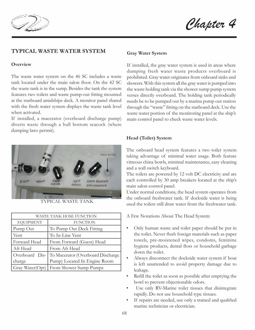
68
Chapter 4
Gray Water System
If installed, the gray water system is used in areas where dumping fresh water waste products overboard is prohibited. Gray water originates from onboard sinks and showers. With this system all the gray water is pumped into the waste holding tank via the shower sump pump system verses directly overboard. The holding tank periodically needs be to be pumped out by a marina pump out station through the “waste” fi tting on the starboard deck. Use the waste water portion of the monitoring panel at the ship’s main control panel to check waste water levels.
TYPICAL WASTE WATER SYSTEM
Overview
The waste water system on the 46 SC includes a waste tank located under the main salon fl oor. On the 42 SC the waste tank is in the sump. Besides the tank the system features two toilets and waste pump-out fi tting mounted at the starboard amidships deck. A monitor panel shared with the fresh water system displays the waste tank level when activated. If installed, a macerator (overboard discharge pump) diverts waste through a hull bottom seacock (where dumping laws permit).
GRAY WATER
TYPICAL WASTE TANK
WASTE TANK HOSE FUNCTIONEQUIPMENT FUNCTION
Pump Out To Pump Out Deck FittingVent To In-Line VentForward Head From Forward (Guest) HeadAft Head From Aft HeadOverboard Dis-charge
To Macerator (Overboard Discharge Pump) Located In Engine Room
Gray Water(Opt) From Shower Sump Pumps
Head (Toilet) System
The onboard head system features a two toilet system taking advantage of minimal water usage. Both feature vitreous china bowls, minimal maintenance, easy cleaning and a wall switch keyboard.The toilets are powered by 12 volt DC electricity and are each controlled by 30 amp breakers located at the ship’s main salon control panel. Under normal conditions, the head system operates from the onboard freshwater tank. If dockside water is being used the toilets still draw water from the freshwater tank.
A Few Notations About The Head System:
Only human waste and toilet paper should be put in • the toilet. Never fl ush foreign materials such as paper towels, pre-moistened wipes, condoms, feminine hygiene products, dental fl oss or household garbage down the toilet.Always disconnect the dockside water system if boat • is left unattended to avoid property damage due to leakage.Refi ll the toilet as soon as possible after emptying the • bowl to prevent objectionable odors. Use only RV-Marine toilet tissues that disintegrate • rapidly. Do not use household type tissues.If repairs are needed, use only a trained and qualifi ed • marine technician or electrician.

69
Systems
Using Later Style Toilet-
To use the on board toilets fi rst make sure the forward and aft 12 volt breakers are activated at the main control panel. If using dockside water make sure water is fl owing from the marina spigot.
The wall control switch is used to add water to the bowl and to fl ush the toilet. Select cycle information is noted below. For more complete information, refer to the toilet vendor information located in the information packet.
1. To add water (est. 17 ounces each cycle ) to the bowl press the add water button momentarily and release. The system prevents overfi lling the bowl.
2. To fl ush the bowl press the fl ush button momentarily and release. The attached bowl motor will macerate the waste and fl ush it. The cycle ends with a small amount of water being added to the bowl to help prevent odors. This completes the minimal water usage fl ush cycle.
Wall Control Panel Blue Backlighting Description:
The holding tank icon in the lower right hand corner • of the control panel is not lighted. Toilet system is off or not receiving power.The holding tank icon is normally green. This means • the holding tank is less than full.The holding tank icon is red. The holding tank is full • or near full with the fl ush lockout (prevents Flush operation when holding tank is full) activated.Tank icon fl ashes • Sleep mode (non-use for 8 hours) causes the lights to • go out. Pushing the fi ll or fl ush button momentarily will return lighting cycle.
Single Flush Override of Flush Lockout
1. If the holding tank is full the fl ush lockout cycle will not allow the bowl to be fl ushed and the fl ush button will be lighted red.
2. For emergency use only the fl ush button can be held for 8 seconds and a fl ush will occur. This can be accomplished because the full sensor connected to the holding tank is usually placed a bit below the actual full capacity of the tank. Flushing more than 5 times using the override feature may force waste into plumbing system. Regal is not responsible for damage to equipment, or injury or death due to overfl ow of waste due when fl ush lockout is overridden. Again, refer to toilet vendor information in the owner’s information packet.
HOLDING TANK
CAUTION!
POSSIBLE OVERFLOWING
OF THE WASTE HOLDING TANK
CAN OCCUR DUE TO USING
THE SINGLE FLUSH OVER-RIDE FUNCTION.
FOR EMERGENCY USE ONLY.
TYPICAL WALL SWITCH
FLUSH
LOCKOUT
ADDWATER

70
Chapter 4
Typical Dockside Pump-Out
There is a fi tting located on the deck labeled “waste.” This fi tting is used to pump out the waste tank. Nor-mally a pump out station is found at most marinas. After removing
the fi tting cover a special hose is inserted into the fi tting and the machine then removes the waste. Normally there is a charge for the service. Make sure they connect the hose to the “waste” fi tting. Of course when cruising in international waters the overboard discharge pump may be used. See the section on using the macerator.
There is a waste fi lter in-stalled in the vent line be-tween the waste tank and the port thru-hull fi tting. See photo above. The fi l-ter’s purpose is to keep
objectionable odors to a minimum from the waste tank. It is recommended that the fi lter be changed yearly. It can be ordered from your Regal yacht dealer or from marine supply stores. Typically the waste fi lter is mounted in the sump (engine compartment).

71
Systems
The macerator (overboard discharge pump) option is located in the engine room. It is connected to a normally closed seacock. In locals where it is approved the seacock is opened and the
macerator is activated through a key switch and button located at the ship’s main salon control panel (shown above). At that point waste travels from the waste holding tank through the macerator pump where it is ground up and then exits through the hull bottom at the open seacock. See the photo.
To Use Macerator (If Installed):
Make sure it is legal to pump waste overboard before starting the operation.
Locate the overboard discharge seacock in the engine room. Usually this seacock can be identifi ed by the stack of tie wraps next to it. Also, look for the incoming hose that runs from the output side of the macerator to the seacock. It is normally a 1 1/2” diameter white hose. Since the seacock by law must be have another means besides the handle to keep it closed the tie wrap serves that need. Cut the tie wrap to access the seacock handle.
Typical Macerator (Overboard Discharge Pump)
KEY SWITCH
MACERATORON BUTTON
MACERATORBREAKER
MACERATOR
SEACOCK INOPENPOSITION
TIE WRAPS
HOSE FROMMACERATOR
MACERATOR SEACOCK
Open the seacock handle. It should be positioned in line with the seacock as shown in the photo.
Activate the macerator breaker at the 12 volt salon main DC control panel.
At the level monitor panel shown above turn the key to the “on” position. With the key switch being held in the “on” position push in on the macerator button to start the overboard discharge. Continue to discharge the waste until the monitor panel shows empty for the waste tank. At this point, shut off the macerator switch, deactivate key switch and turn macerator breaker to the “off ” postion.
Close the seacock handle. It should now be at a 90 degree angle to the seacock.
Use a tie wrap and refasten the seacock handle tightly so it can not be moved.
At this point you may desire to add an approved holding tank deodorant by fl ushing the correct amount down the toilet.

72
Chapter 4
POSSIBLE PROBLEMS/SOLUTIONS-WASTE SYSTEM-LATER MODELS
1. Toilet does not fl ush or fl ushing perfor-mance is poor. The holding tank indica-tor is lighted red at the toilet control panel wall switch. The holding tank is full and needs to be pumped out. Also, there could be a clog at the water pump inlet.
2. No water in bowls during fl ush or add water cycle. Check to make sure the main water supply has not been turned off along with the fresh water pressure pump.
3. There is no light on the toilet wall control panel or it does not stay lighted. Check the head breaker on the main ship’s control panel. Also, the wall panel could of entered the Sleep mode cycle after 8 hours of inactivity.
4. There is an odor of sewage onboard. Check the vent fi lter. It should be replaced annually at the beginning of the boating season. Also, check the waste tank, fi ttings, and related hoses throughout the vessel.
5. When running the overboard discharge pump is not pumping out the waste. Check to make sure the deck waste cap is securely fastened and O ring is not missing.

73
Systems
TYPICAL WASTE SYSTEM-LATER MODELS
1. Toilet Bowl2. Solenoid Valve3. Fresh Water Pressure Pump4. System Vent5. Holding Tank6. Fresh Water Tank (System can also run from dockside water supply)
5 6
Forward Head Aft Head
To 12 Volt MainControl PanelFwd. Head Breaker
To 12 Volt MainControl Panel Aft Head Breaker
To 12 Volt MainControl PanelFresh Water Pressure PumpBreaker
Wall Control Panel

74
Chapter 4
POSSIBLE PROBLEMS/SOLUTIONS-VACUUM FLUSH SYSTEM-EARLIER MODELS
1. Water leaks out of toilet bowl. The seal could have something caught in it.
2. Toilets cycle every few minutes instead of once about every 30 minutes. Check system for air leak.
3. Pump emits odor. Check pump for loose hoses or con-nections.
4. Toilet will not fl ush. Open fl ush valve & check orfi ce at the bottom of the base. Also, check vacuum pump, generator and vacuum tank for obstruction.
5. Blockage between toilet and vacuum generator. Check for foreign object in lines. Also, check for excessive toilet tissue.
6. Water does not shut off in toilet. Check for debris in water valve.
7. Water does not enter toilet bowl properly. Make sure water supply is suffi cient and breakers are activated at the ship’s main control panel. Also, check the water valve for debris.

75
Systems
TYPICAL WASTE SYSTEM-EARLIER MODELS
TOILET BOWL ASSEMBLY-EARLIER MODELS

76
Chapter 4
TRIM TAB DASH SWITCH
PORT ROCKER
STBD. ROCKER
Using trim tabs will compensate for uneven weight distribution, listing, water conditions, wind velocity and other factors that cause ineffi cient operation.
TRIM TAB
TRIM TABS
Trim tabs are installed on the lower hull at the transom area. Water is defl ected and redirected as the trim tabs are raised and lowered from the dash switches. This change in water fl ow creates upper pressure under the tabs, and raises the stern. When the stern rises, the bow is lowered. Lowering the port tab will cause the port stern to rise, making the starboard bow lower. Lowering the starboard tab will cause the starboard stern to rise, making the port bow lower.
Obtaining A Trimmed Position
Your Regal yacht reaches a planing position at a designated speed. This speed is determined by bottom design, weight distribution, water conditions, and on board equipment. As the throttle is advanced the stern squats and the bow rises initially. The trim tabs allow your boat to plane at a slower speed than natural conditions allow. In short bursts both trim tab rocker switches are pushed simultaneously in the “bow down” position which causes the trim tabs to move down. As the boat breaks over the bow high attitude the boat speed accelerates and visibility increases.If the boat is over trimmed, it will plow the bow and the boat will lose maneuverability. If this occurs, simply short burst the “bow up” trim tab rocker switches simultaneously.In the “learning curve” process, press the tab switches in half second bursts. You will notice a slight delay from the time the switches are pushed until the boat reacts depending on vessel speed. You will know after awhile the optimum planing angle and speed.When running in heavy seas press the “bow down” position which will assist the vessel to cut through the waves. This will produce a drier and more comfortable ride.

77
Systems
When trimmed or in the bow down position, the bow spray is farther forward, the wake is smaller, and positioned further behind the vessel. Also, when trimmed you will notice that the tachometers show an increase in rpm’s.
Rectifying A List
Your vessel can use the trim tabs to rectify a list. The trim tabs adjust the boat’s attitude in the direction the helm rocker switch is pushed. If the port bow is high, push the left-hand “bow down” direction on the dash rocker and the port bow will lower. If the starboard bow is high, push the right-hand “bow down” direction and the starboard bow is
lowered.
Porpoising is a running condition where the bow “bounces” up and down similar to a porpoise motion. Press “bow down” in one-half second bursts. As the trim tabs turn, the porpoising should recede and the vessel speed should increase. Only a small amount of “bow down” is normally necessary to make this change.
Porpoising

78
Chapter 4
CONVERTIBLE HARDTOP OPERATION
Your Regal sun coupe features a convertible hardtop (sometimes called a sunroof). Normally a motorized belt driven system is used to open and close the hardtop sun-roof. The slide mechanism travels forward and aft on dual rails. A cockpit switch activates the hardtop. Read and un-derstand the warnings regarding the hardtop.
To open or close the sunroof:
1. Find the hardtop switch. It is located on a switch pan-el located near the passenger helm area. 2. Press hardtop switch (A) to open or close the sunroof slid-ing panel. 3. Should the switch fail to op-erate check the breaker located
at the helm locker breaker panel. 4. Close the sunroof when leaving the vessel for extended periods.
A
TO PREVENT POSSIBLE BODILY INJURY KEEP ALL BODY PARTS
AWAY FROM THE SUNROOF!
WARNING!
TO PREVENT BODILY INJURY DUE TO FALLING
DO NOT STEP ON THE SUNROOF HARDTOP! USE THE WALK-AROUND LOWER DECK
AND HANDRAIL SYSTEM TO ACCESS ANY HARDTOP OR SUNROOF
COMPONENTS.
WARNING!
POSSIBLE PROBLEMS/SOLUTIONS-SUNROOF
1. The sunroof is stuck open. On select models you can remove the rear trolley fasteners. At that point the center of the bracket can be raised over the belt drive bracket which will free up the belt. The sunroof can now be closed manually. Use
caution when manually closing the sunroof. Install duct tape as needed to keep sunroof panel closed.
2. Sunroof does not open/close. Check the breaker lo-cated at the electronics locker next to the helm seat. If breaker is good contact your closest Regal yacht dealer for more information.

79
Systems
TYPICAL WINDLASS
INTRODUCTION
Using the anchor windlass requires knowledge of the anchoring process to understand the correct amount of rode and scope required. Read the section on anchoring, the windlass operation manual and understand all safety information before attempting to run the windlass. Also, since anchoring is one of the skills the skipper should master for cruising “peace of mind” visit your local library or “surf ” the internet to locate further information regarding anchoring techniques.
WINDLASS SAFETY TIPS & WARNINGS
Never use the windlass to tow or pull a boat.• Never use the windlass for securing the anchor line. • Instead use a deck cleat.Never drop anchor in the vicinity of divers or • swimmers.Never wrap chain around the drum.• Never use the windlass to pull up a person.• Never use windlass to break anchor loose.•
Always strive under normal conditions for a 7:1scope • ratio on the anchor line.Always remove the handle from the gipsy when • operating windlass from the foot controls. Always turn the windlass deck switch to the “off ” • position when not in use.Always secure the anchor chain lock in “locked” • position in foul weather.Always keep an eye on the rope/chain locker to avoid • rope buiding up under the hatch.Always manage the retrieval process carefully to • prevent the anchor from hitting the boat.
TO PREVENT POSSIBLE BODILY INJURY TURN OFF ALL WINDLASS POWER SOURCES
BEFORE PREFORMING ANY WORK ON ANY WINDLASS COMPONENTS!
WARNING!
TO PREVENT POSSIBLE BODILY INJURY KEEP ALL BODY PARTS AND LOOSE
CLOTHING AWAY FROM WINDLASS MOVING PARTS!
WARNING!
WINDLASS ANCHOR LINE
Although several variations exist the windlass is normally outfi tted with 3/4 “ twisted nylon line and 7/16” chain. With this combination the vessel meets normal working load conditions and the rope/chain combination protects the rode. The heavier chain lowers the angle of pull and helps bury the plow anchor which increases the holding power. When the plow anchor is buried the chain is protected from bottom chafi ng as the vessel is moved around due to current, waves and wind conditions. Several methods of securing the anchor to rode are used today including eye splices, thimbles and shackles. Regal uses a set of hexagon threaded pins which are lock tight-ened in place. This method provides a clean fi nish and prevents loosening due to vibration. The bolts may be re-moved when necessary by using a hex fi tting on a ratchet wrench.The plow anchor featured on your Regal yacht has dem-onstrated to be effi cient in a variety of sea bottoms. Ex-perts say the verdict is still out on a grassy bottom but unfortunately some grasses or weeds resist penetration by any anchor.

80
Chapter 4
TYPICAL WINDLASS HARDWARE
CLEAT
CHAINLOCK(STOPPER)
FOOTSWITCHUPFOOTSWITCHDOWN
ROPELOCKER
CHAIN
WINDLASSSWITCH
WINDLASS
ROPE
ANCHORSHANK
WINDLASS COMPONENTS
The windlass is used to au-tomatically raise and lower the anchor. Before attempt-ing to lower the rope/chain rode check the rope locker for tangled rope or chain. On earlier models, remove the safety lanyard from the anchor chain.
As seen in the illustration above open the center deck locker to gain access to the windlass switch. The switch “off ” position is at 12 o’ clock. With the switch “on” position (shown above) at 3 o’clock the foot switches are energized. If the foot switches have no power check the breaker located in aft stateroom electronics locker.
The chain lock (stopper) is used to hold the chain portion of the anchor line assembly and does not effect the ny-lon anchor line. Before using the windlass make sure the chain lock (stopper) is positioned with the lever pointing toward the stern.The chain lock “dances” or ratchets over the chain while the process of retrieving the anchor rode is underway. The chain stopper will lock the chain once the anchor is completely retrieved into the bow pulpit chute.
TO BOW
TO STERN
CHAIN LOCK(STOPPER)
CHAIN LOCK LEVERPOSITIONED TO ENGAGE CHAIN
SWITCH SHOWN IN“ON” POSITION
OFF
ONNote: Make sure the chain lock (stopper) is positioned to engage the chain once the anchor is retrieved. This prevents the chain from paying out under abnormal conditions or when a weakened gipsy clutch condition exists.

81
Systems
TYPICAL WINDLASS OPERATION
Paying Out Anchor
Ensure both the battery switch at the battery manage-1. ment panel and deck foot switch are energized.Check the anchor rope locker for proper anchor line 2. alignment. Untangle any crossed lines.Check the proposed anchoring area for swimmers or 3. divers.Position vessel at proposed anchor drop site.4. Check that pawl is in disengaged position.5. Make sure chain stopper is in a released position. 6. Step on the 7. down foot switch to pay out the chain and anchor line. When the anchor hits the sea bottom disengage the foot switch. While the captain “bumps” the vessel in slow speed 8. reverse pay out the anchor line until the correct scope is reached. When scope is reached secure the anchor line around 9. a cleat. Never use the windlass as the sole means of holding the anchor. Check the anchor position by checking the postion 10. using the GPS. The GPS features an anchor alarm. Refer to the GPS owner’s manual for further infor-mation.
UP FOOT SWITCH DOWN FOOT SWITCH
On select models bow foot switches are used to control the windlass. To use the foot switches remove the pro-tective caps. When you energize the up foot switch the anchor is retrieved. When you energize the down foot switch the anchor is payed out. After the anchoring pro-cess is completed close the protective caps.
BOW

82
Chapter 4Retrieving Anchor
Check the anchor locker for any tangled lines.1. Ensure both the battery switch at the battery manage-2. ment panel and deck foot switch are energized.Undo the anchor line at the cleat.3. Step on the 4. up foot switch to retrieve anchor line as the captain “bumps” the vessel toward the anchor while maintaining a relatively straight anchor line po-sition. Note: Breaker may blow if the captain does not bump the engines in gear due to the pressure on the windlass. Once the vessel is over the anchor and it is broke free 5. continue to retrieve the anchor. Check the anchor locker for tangled line and sweep the looped line out of the way if locker is fi lling up with line.Once the anchor is approaching the bow slow down 6. the windlass to ensure proper entrance at the chute and to avoid hitting the bow. Once the anchor is completely retrieved “bump” the 7. down foot switch to lock the chain.As soon as possible after the cruise use the bow lock-8. er washdown to rinse off the anchor, chain and line. Coil the line on deck to air dry. This will aid in pre-venting mildew and salt deposit build-up.
Independent Warping
Once the primary rode is secure the drum can be used for docking or an additional rope only rode. To use this feature:
Make sure the chain lock • is secured.Pawl to be in disengaged •
position.Disengage clutch by in-•
serting the winch handle (mounted in deck locker) in top nut and turn coun-ter-clockwise 1/2 a turn. Remove handle and store •
in its designated location.The drum will operate independently from the gipsy. • When fi nished using drum, insert winch handle in top • nut and turn clockwise 1/2 turn to re-engage clutch.
TYPICAL WINDLASS
DRUM
NUT

83
Systems
Manual Free Fall
The anchor can be dropped without the use of battery power with this feature. To use:
Check that pawl is in disengaged position. • Release the chain stopper.• Insert winch handle in top nut. Loosen top nut by •
turning counter-clockwise until anchor drops. Control the rate of fall with handle. • Once paid out fully tighten top nut.•
To avoid possible bodily injury and/or property damage read and understand the windlass operation manual before attempting to use the windlass or anchor components.
TYPICAL WINDLASS SYSTEM OVERVIEW
TYPICAL WINDLASS-SAFETY WARNINGS
♦ Ensure that limbs, fingers, hair and clothing are keptclear of the windlass and anchor during operation.
♦ Check to see that there are no swimmers or divers nearby before dropping the anchor.
♦ Remove the handle from the gipsy when operating the windlass from the foot controls or helm switch power.
♦ Always turn the windlass power suppy to the “off ” position when not in use.
♦ While at anchor, the load on the chain/rope must be transferred to a cleat.
♦ Do not use a windlass as a holding device for towing.
♦ Never use a windlass to lift a person, boat, etc.
♦ Check to make sure the permit switch is locked when the windlass is not in use.
♦ Remove the anchor safety lanyard before powering up the windlass.
♦ Fasten the anchor safety lanyard immediately after the anchor is positioned at the bow.
♦ Do not attempt to pull a load greater than the rated load of the windlass.
♦ Always use the vessel’s engines to aid anchor recovery.
♦ Refer the the windlass manufacturer’s owner manual for more detailed operating and maintenance information.

84
Chapter 4
TYPICAL ENTERTAINMENT SYSTEM
OVERVIEW
Your yacht features a variety of standard components that provide both visual and audio entertainment. In addition, there are optional systems that are noted in the follow-ing pages. Regal reserves the right to delete, add, or change both standard and optional components at anytime without notice.Note: The information found in the following pages is for current models only.Please refer to the individual owner’s manuals and the technical sec-tion (schematics) for further entertainment system information.
Preparing To Use Entertainment System-Breakers
Before using any portion of the entertainment system it is necessary to activate the 12 volt “house” battery switch located at the battery management panel. In addition, the generator (at sea) or the dockside cord (at mooring) must be activated to supply AC voltage for the TV monitors. Also, depending on the entertainment component desired the following breakers may need to be activated:
12 Volt- TV Antenna, Satellite TV System, Dash Main (Fusion System)
120 Volt- Salon TV, Aft Stateroom TV 1, Fwd. Stateroom TV, Fwd. Stateroom TV, Cockpit TV
Now that the breakers are activated continue to the Quick Reference Entertainment Guide on the next page. Here the Bose master remote control is used to operate the dif-ferent entertainment system components.Note: When using the Quick Start portion of the Quick
Reference guide card make sure the Bose On/Off button (white) is activated. It turns the entire salon system on via the remote control.
Antenna Switch
The antenna switch features 2 buttons labeled A and B to choose the desired antenna signal source. It is located in-side the aft salon entertainment center overhead cabinet. See the salon entertainment system layout on the follow-ing page.
Note: Activate the TV antenna breaker. Follow the in-structions below.
At Dockside- After the television coxial cable is plugged into the vessel coxial receptacle and the marina dock box press the A antenna switch button completely in until it catches. At this point the marina TV signal is available to view onboard televisions.
At Sea- Press the B antenna switch button completely in until it catches to activate the saucer-shaped television antenna mounted on the hardtop.
To deactivate either antenna switch, push the switch com-pletely in; then release.
When cruising you may encounter a marina without a working shore signal so your backup is to use the ship’s antenna. This is more common with older marinas lo-cated off the more traveled waterways.
ON BUTTON
A/B ANTENNA SWITCH
AA BB

85
Systems
Quick Reference Entertainment Guide
Located in the owner’s information packet there is a plas-tic placard (see above) to assist in using the basic enter-tainment systems. This card on one side displays a quick start page and on the other side displays a transition page. Note that the salon television and entertainment system must be powered on before the transition page can be used. Use the Bose master remote control to operate the salon entertainment compo-nents.
Read and understand the outlined information on both sides of the cards before operating the entertainment system components. In addition, please become familiar with each of the en-tertainment component owner’s manuals which are lo-cated with the owner’s information packet. Note that a portion of the equipment may not be installed on your yacht since that component may be optional.
TV CBL SAT AUX
CD DVD FM AM
TV CBL SAT AUX
CD DVD FM AM

86
Chapter 4
Salon Entertainment System
Media Center Overview
The media center is the main component for the salon entertainment center. The media center functions can be controlled through the Bose master remote control or at the media center itself.
The media center:
Controls the system on and off power.1. Displays and sets desired play options.2. Controls the system volume level.3. Selects the next available radio preset.4. Opens and closes the CD-DVD disc tray.5.
Note: When you use the media center source but-ton to control a function the master remote con-trol will not control that component. Since the Bose master remote control is easier to use it is recom-mended as the fi rst option for all component choices. In addition, the QUICK REFERENCE CARDS are set up using the Bose master remote control.
Important note: When using the Bose master remote control make sure the salon entertainment center door is open or the IR signal will not communicate with the components. Normal range of operation for the remote control is close to 20 feet.
Bose Master Remote Control-Batteries
The Bose master remote control requires 2 AA batteries. It is a good idea to keep extra batteries onboard since a remote seem to quit when you need it the most. One clue that a remote control needs new batteries is when you change channels and it will not go up or down as channels are selected or the television will not come on.
Television Remote Control
The original television remote control is still used to con-trol select television functions including set-up menus such as language, station settings and internal picture controls such as brightness, contrast and screen pixels.
TYPICAL SYSTEM COMPONENTS
TYPICAL MEDIA CENTER

87
Systems
DVD-CD
The media center houses the DVD-CD disc tray. Follow the directions on the quick reference cards to play the desired disc. As an option, the control buttons can be used on the top of the media center.Note: When you use the Source button on the media center to select a component for play such as DVD-CD the Bose master remote will not control that source.
Checking For Disc Compatibility
If you encounter a problem when attempting to play a disc, check to make sure it is one of the compatible types as shown below.
Disc Care
Dirt or scratches on a disc can prevent it from playing properly.
You can avoid this problem by:
Handling all discs by their edges to prevent fi nger-1. prints and scratches. Return them to their cases after use.Avoiding exposing discs to chemical products that 2. can cause damageWriting directly on a disc or on a label attached to the 3. disc.Direct sunlight, high temperatures, and humidity.4. Always use a soft, dry and lint-free cloth to clean the 5. disc. Wipe straight out from the center to the edge.
DO NOT USE ACIRCULAR MOTION
WIPE STRAIGHT OUT

88
Chapter 4
POSSIBLE PROBLEMS/SOLUTIONS
1. TV channels using the master remote control are sluggish to change or will not change up or down.
Change out the remote control batteries.
2. After a cruise and hooking up coaxial cable to the dock box the on board television sets do not display a picture.
Check to make sure the A/B switch is in the shore posi-tion.
3. The Fusion cockpit stereo does not play with the salon television on.
The salon television must be in the “off ” position for the cockpit stereo audio to be heard through the salon enter-tainment system speakers.
4. Starting with the transition quick reference guide the desired components do not function.
Remember to use the transition guide the TV and the entertainment center must already be on.

89
Systems
TYPICAL SATELLITE TV
If installed, the satellite television option features viewing hundreds of tele-vision channels using the salon TV. Basically, the sig-nal is transmittted through an antenna system installed
on the hardtop which features a satellite tracking system that automatically fi nds the satellite for crystal-clear tele-vision reception.
System Components-Antenna
The antenna is small yet powerful. It has a diameter of 37cm but operates to levels of other 45cm units. The antenna uses modern technology to quickly acquire and track the correct satellite, switch between satellites, and send signals to the interface box. Internal gyros allow the antenna to track the satellite at all times, even with the vessel on the move!
Interface Box-Controller
The interface box supplies power to the antenna system and delivers satellite TV signals to the satellite receiver. This component is also used to set-up the LCD display.
Television Receiver
The Dish network receiver has been chosen because of its compatibilty with the KVH components. This unit re-ceives HD (high defi nition) signals from 3 DISH network satellites. The antenna then switches between these 3 sat-ellites as needed as you change channels using the Bose master remote control.
Television
The salon television delivers true high defi nition recep-tion and is multi-functional with other entertainment components.
The satellite television operation is user friendly. Refer to the quick reference cards to activate the satellite func-tions. Use the Bose master remote control to change channels when in the satelllite mode.
Note: If the optional 2nd satellite television system is installed the master stateroom will have separate satellite television capability us-ing the 2nd Bose system master remote control. This will enable both the salon and master stateroom the ability to receive and view television channels indepen-dently from each other.

90
Chapter 4TYPICAL STEREO
The stereo is normally located at the helm. It can be played through the salon Bose system or independently at the cockpit. The unit features an iPOD inside the wa-terproof cover. To use the Bose audio feature turn the dash breaker to the “on” position. Activate the Fusion radio at the helm. Note that the salon TV must be off to receive the Fusion audio signal. Follow the remainder of the steps on the quick reference card to receive the Fusion audio signal.See the Fusion owner’s manual for further information.
t
ON BUTTON
iPOD-INSIDEFUSION COVER

91
Systems
TYPICAL ELECTRONICS
Later yachts feature Garmin electronics. If installed, the package may include waterproof cameras with true day/night operation, dual chartplotters, heavy duty open-array radar, auto pilot, sonar with full-featured depth sounder functions, VHF radio with DSC capability and XM satel-lite weather radio. Operating information for later model electronics can be found at www.garmin.com or in the owner’s information packet. Select earlier yachts feature Raymarine electronics. Oper-ating information for these products can be found at www.raymarine.com/ or in the owner’s information packet.
Note: The operation of the above electronic components will be out-lined. A portion of the components are optional and may not be installed on your yacht. Earlier yachts may have different systems and/or components onboard.Please refer to each vendors owner’s manual for in-depth information regarding individual electronic components. Regal reserves the right to upgrade, change, modify, or eliminate any system or component at anytime.
System Operation Overview
To operate the electronics the following switches need to be activated:
1. Make sure the battery switch located inside the star-board stairway locker is activated. To perform this func-tion turn the “house” battery switch to the “on” position as shown by the arrow in the illustration.
2. Activate the “electronics” switch at the helm panel which controls power to the GPS antenna and the auto pilot.3. At this point each individual component can be acti-vated.
Refer to the illustrations for further information.
Notice the electronics breaker as shown above. If the electronics group does not power up, check to ensure this breaker is activated. Always fi nd the source of a tripped breaker problem before reactivating it. Press the breaker in to reset it.
Electronics: Helm Switch

92
Chapter 4
Chartplotter
Single chartplotters are standard on your yacht. Dual chartplotters are optional but are required for a por-tion of the other electronic options. The unit(s) feature a touchscreen, NMEA 2000 compatible, multifunction display, pre-loaded with U. S. coastal maps and interfaces with other electronic components through the Garmin Marine Network. It displays graphics with crisp, video-quality resolution. With the dual chartplotters and the op-tional camera monitoring system, you can keep tabs of your main salon and deck activity.
Chartplotter Operation
Before operating the chartplotter(s) read and understand the vendor supplied owner’s manual including all the warning information. As mentioned before some yachts display the optional dual chartplotters. These chartplotters feature “touch” screens. When you see information groups on the screen use your fi nger to touch the format desired. With some information in par-ticular it is required that you actually drag an object by us-ing your fi nger and keeping it on the screen as you move the object.
A. To power the system up turn the “house” battery switch to the “on” position at the battery management panel.
B. Next, turn the helm electronics switch to the “on” po-sition. This powers up the GPS antenna and the auto pi-lot. The chartplotter(s) is now ready to power up.
C. Press and release the chartplotter power key. When the warning screen appears, touch I agree. At this point you will be taken to the home page screen.
Note: If dual chartplotters are installed, you can power up either one by pressing and releasing the power key or by pressing and releasing both power keys.
Note: If one chartplotter is connected, the chartplotter shuts down. With dual systems, a prompt asks if you want to turn off the entire system. Touch yes to turn off the entire network, or touch no to put chartplotter in sleep mode.
Home Screen
Charts- Selects navigational charts and radar overlay func-tions.
Sonar- Sets up and provides sonar information through the optional transducer.
Combinations- formats screen to view a chart, sonar, radar, and video cameras (2 cameras on each chartplotter; re-quires the extra chartplotter option).
Information- Shows tide conditions, currents, celestial data, information about other vessels, your yacht’s instrumen-tation, and video.

93
Systems
Mark- Marks, edits, or deletes your current location as a waypoint or Man Overboard
Where To?- Searches and navigates to service areas, routes and waypoints.
Radar- Sets up and displays radar (requires open array ra-dar option) Radar unit is installed on hardtop.
Weather- Sets up and displays various weather information including precipitation, forecast, fi shing, sea conditions, and visibility (Only available with the satellite weather op-tion and subscription).
Confi gure- Permits the editing of chartplotter system set-tings (Can set a simulator mode where you can practice using most of the chartplotter functions).
Man Overboard- Marks your current position as a waypoint, and sets a course back to the marked location.
Once you are able to navigate to the home screen each of the electronic onboard components can be formatted and adjusted to meet individual needs and the fi ner points of cruising requirements. Continue to read the electronic owner’s manuals for adjusting the fi ner settings on the chartplotter(s).

94
Chapter 4
Typical Radar
RADAR PRODUCES ELECTROMAGNETICENERGY WHICH IS HARMFUL.
TURN THE RADAR OFF WHEN PERSONNELARE SERVICING THE UNIT OR EQUIPMENT CLOSE BY.
WARNING!
CAUTION!AVOID POSSIBLE DAMAGE TO THE EYES
DUE TO ELECTROMAGNETIC ENERGY.
WHEN RADAR IS TRANSMITTING
DO NOT LOOK DIRECTLY AT THE ANTENNA
AT CLOSE RANGE.
Radar Operation
Read the radar operator’s manual for learning all the fea-tures of the radar component. It is a good idea to use the manual along side the chartplotter to learn the basic radar operation. At that point you can branch out with the manual on the secondary functions of the radar. Pay special attention to all safety and warning labels in the operatior’s manual.
Since the radar unit is part of the vessel electronic marine network you will be able to use the chartplotter as your network screen and have the capability to overlay the ra-dar image on the chartplotter map page.
RADAR & TV ANTENNAOPEN ARRAY RADARSHOWN

95
Systems
Typical Autopilot
The autopilot was developed specifi cally for the Volvo Inboard Performance System and Joystick system which is the propulsion type used on your Regal yacht. If installed, the autopilot is part of the onboard marine network and therefore can be programmed to maintain a course through the chartplotter route. Easy-to-use setup provides carefree auto-guided navigation in open waters.
Autopilot Operation
The autopilot continuously adjusts the steering on your yacht to maintain a constant heading. The unit can be programmed for both automatic and manual steering functions and patterns. Before using the auto pilot, be sure to read and under-stand the autopilot operation manual located in the own-er’s information packet.
TO PREVENT POSSIBLE BODILY INJURY, DEATH OR PROPERTY DAMAGE,
NEVER LEAVE THE HELM UNATTENDED. BE PREPARED AT ANY TIME
TO PROMPTLY REGAIN MANUAL CONTROL OF YOUR YACHT.
WARNING!
STANDBYSOFT KEYS
POWER
STATUS
HEADING
ACTUAL HEADINGMARKER
PATTERN
Follow these steps to start-up the autopilot;
1. Energize the “house” battery switch at the battery management system panel located at the cockpit stairway locker.
2. Turn on the helm electronic switch.
3. Press and hold the power button briefl y to turn the au-topilot on or off. If the power button is released quickly instead of briefl y holding it the unit will seek the display adjustment screen verses the main screen.
General Operation Keys & Descriptions
Power- Turns the autopilot on and off.
Soft Keys- These keys help to navigate the menus, select items, and change the autopilot steering bearing. The center soft key is used to select highlighted items and open a menu. The left soft key is used engage the unit or to move back one screen. The right soft key to navigate through the menu screens.
Note: Press a soft key to activate the action indicated directly above it.
STBY (Standby)- Press this button to start the standby function. Press STBY to stop the autopilot from any menu screen at any time. A time when you use STBY might be when you are beginning your route through a tight turning channel to a marina or to your favorite on the water restaurant.
Note: When you place the autopilot in standby mode be ready to regain manual control of the boat steering system.
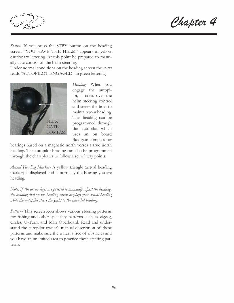
96
Chapter 4
Status- If you press the STBY button on the heading screen “YOU HAVE THE HELM” appears in yellow cautionary lettering. At this point be prepared to manu-ally take control of the helm steering. Under normal conditions on the heading screen the status reads “AUTOPILOT ENGAGED” in green lettering.
Heading- When you engage the autopi-lot, it takes over the helm steering control and steers the boat to maintain your heading. This heading can be programmed through the autopilot which uses an on board fl ux-gate compass for
bearings based on a magnetic north verses a true north heading. The autopilot heading can also be programmed through the chartplotter to follow a set of way points.
Actual Heading Marker- A yellow triangle (actual heading marker) is displayed and is normally the bearing you are heading.
Note: If the arrow keys are pressed to manually adjust the heading, the heading dial on the heading screen displays your actual heading while the autopilot steers the yacht to the intended heading.
Pattern- This screen icon shows various steering patterns for fi shing and other speciality patterns such as zigzag, circles, U-Turn, and Man Overboard. Read and under-stand the autopilot owner’s manual description of these patterns and make sure the water is free of obstacles and you have an unlimited area to practice these steering pat-terns.
FLUXGATECOMPASS

97
Systems
Typical Sonar
If installed, the sonar system used on your yacht pro-vides full-featured depth sounder functions through the chartplotter. The sounder connects through the Garmin
Marine Network and shares various data with all connected chartplotters.It consists of a sound-er located in the elec-tronics locker in the master stateroom. It connects to a trans-ducer. The boat trans-ducer bounces signals from the sea bottom through the sounder and to the chart plot-ter for viewing. These signals may include depths, water temper-ature and objects be-tween the hull bottom and the sea bottom such as fi sh. See the display which offers a sampling of possible
sonar information available to your yacht. Read and understand the sonar owner’s manual. It will aid in interpreting the various signals shown on the chart plotter display and show the versatility of the sonar com-ponent.
SOUNDER
TRANSDUCER
SONAR FULL SCREEN
98
Chapter 4Typical Satellite Weather
If installed, later satellite weather features a weather re-ceiver located in the forward deck rope locker area. It looks like a hockey puck. The receiver sends satellite weather information to the chartplotter for display. Along with the receiver an active subscription is required to re-ceive satellite weather.The weather information is received from reputable weather data centers such as the National Weather Ser-vice and the Hydrometerological Prediction Center. Since weather information is broadcast at fi ve second intervals the weather receiver must obtain new data before it can be shown. Therefore, there might be a delay before new weather data appears on the map.Read and understand the XM weather information locat-ed in the chartplotter owner’s manual before attempting to use the weather option.

99
Systems
Typical Engine Management System
If installed, the digital gauges can be displayed on the chartplotter(s) through the home screen. Touch informa-tion, helm gauges and engine menu.Also, at the home screen helm gauges can be accessed by touching combinations. From the next screen, pick the de-sired combo. Go to menu, change combination and choose the desired function 1-4. By using the > and < symbols you can access the differ-ent gauge combinations and choose the one gauge screen or multiple gauge screens for that function. Read and understand the chartplotter owner’s manual be-fore attempting to operate the vessel using these chart-plotter functions.
Below are several combinations showing gauge function samples.
Read and understand the chartplotter owner’s manual be-fore setting the engine management function to gain in-sight into the engine gauge screen selection process.

100
Chapter 4
Typical Camera Monitoring System Option
If installed a camera moni-toring system features cam-eras mounted to provide all round vision. Normally cam-eras are mount-ed on the hard-top for forward and aft vision
and in the salon.These cameras blend in with the yacht aesthetics and are built for day and night operation. They provide high reso-lution images, are waterproof and are constructed to be vandal proof.The cameras are monitored through the chartplotter sys-tem. Each plotter can display 2 different cameras.To view the yacht cameras if installed start from the home screen, touch information and then video.Touch menu to setup source which selects the video device (video 1 or video 2) that displays the video.You can alternate between 2 video sources by touching al-ternate to defi ne the time limit for the screen display.
Note: On new yachts make sure the lens protector fi lm has been removed. The camera view will be hazy if the fi lm is covering the lens.
Typical VHF Marine Radio
The standard yacht VHF marine radio features up to 25 watts of transmitting power and DSC capability. There are dedicated soft keys linked to a screen to select and view the information the yachtsman needs.The radio is interfaced to the chartplotter which permits you to obtain mayday signaling and a digital broadcast of your boat’s position. The unit offers premium sound quality so each message is loud and clear. Also, the VHF receives NOAA weather alert information.Read and understand the vendor supplied information on the operation of the unit. Be sure to train a crew member on how to use the component should the captain become unable to carry out his duties.

1
Engines & ControlsOVERVIEW- FUNDAMENTALS
AVOID SERIOUS INJURY OR DEATH!READ ALL MANUFACTURER’S ENGINE
AND PROPULSION MANUALS BEFORE STARTING OR OPERATING
THE VESSEL.
WARNING!
NEVER RUN ENGINES WITHOUT WATER. DAMAGE TO THE WATER PUMP, IMPELLER,
AND OTHER ENGINE PARTS WILL OCCUR.
CAUTION!
Note: Your Regal yacht dealer has been factory trained on the various yacht systems. Consult your Regal yacht dealer for further information regarding technical support and parts.
This chapter introduces the IPS propulsion system-both diesel engine and drive. This is not to be thought of as a complete workshop manual. This manual will highlight a portion of the engine and IPS information Read the Volvo engine manual carefully and understand the operation as well as the necessary maintenance requirements of the engines and related IPS drive system components before operating the
vessel. Contact your closest yacht dealer or Volvo repair facility for maintenance or parts needs.Always begin maneuvering in a controlled environment where you can practice shifting and docking operations at your own pace. Learn how the vessel’s engines and propulsion systems behave at different speeds, in varied sea conditions, and under light and heavy loads. Always keep the safety of others in mind as you practice docking with the joystick control. Learn to monitor the helm gauges, electronic equipment, and warning systems as they are your on board friends. Read all safety labels and practices. Review with a crew member all the component operations in case the captain would became unable to carry out his duties as skipper.
2
Chapter 5
ENGINE BREAK-IN: ALL MODELS
Diesel propulsion systems require a pre-determined “break in” period. During this time the engine should not be run at a full load condition for extended periods. Various engine load and speed conditions assist the inter-nal engine parts such as bearings, valves and piston rings to “seat” properly which will help ensure a longer engine life. See operator’s manual for further information.During the “break in” period it is necessary to check the engine oil more frequently since it is normal that the en-gine will use more oil. If engine oil is required be sure to check the engine manual for proper grade and viscosity.Check the maintenance schedule in your engine owner’s manual and contact your Regal yacht dealer to set up the fi rst maintenance inspection. Normally the engine oil, fi lters, and drive oil inspections and maintenance are performed during this inspection along with other items. Never exceed a 12 month period between oil changes es-pecially with diesel power since sulfur tends to enter the lubrication system through the fuel combustion process over a period of time.
OIL CHANGES (ENGINE & DRIVE)
Be sure to read the owner’s manual regarding engine oil change recommendations along with IPS stern drive oil. Be sure to follow the Volvo recommended oil type and viscosity. The engine oil change is an important factor in obtaining engine longevity since impurities enter the crankcase through the combustion process and build up in the engine oil. Be sure to check the drive oil on a periodic basis and change it using the recommended type per the engine owner’s manual.
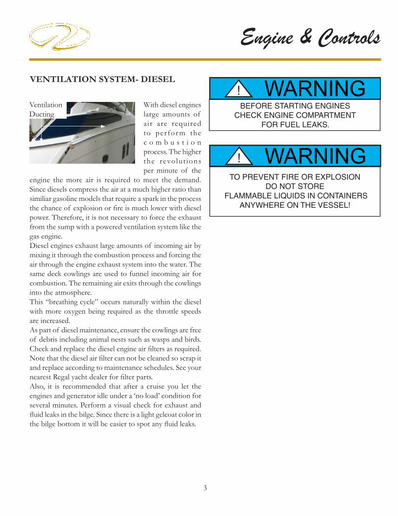
3
Engine & Controls
VENTILATION SYSTEM- DIESEL
TO PREVENT FIRE OR EXPLOSIONDO NOT STORE
FLAMMABLE LIQUIDS IN CONTAINERSANYWHERE ON THE VESSEL!
WARNING!
WARNING!BEFORE STARTING ENGINES
CHECK ENGINE COMPARTMENT FOR FUEL LEAKS.
With diesel engines large amounts of air are required to perfor m the c o m b u s t i o n process. The higher the revolut ions per minute of the
engine the more air is required to meet the demand. Since diesels compress the air at a much higher ratio than similiar gasoline models that require a spark in the process the chance of explosion or fi re is much lower with diesel power. Therefore, it is not necessary to force the exhaust from the sump with a powered ventilation system like the gas engine. Diesel engines exhaust large amounts of incoming air by mixing it through the combustion process and forcing the air through the engine exhaust system into the water. The same deck cowlings are used to funnel incoming air for combustion. The remaining air exits through the cowlings into the atmosphere. This “breathing cycle” occurs naturally within the diesel with more oxygen being required as the throttle speeds are increased. As part of diesel maintenance, ensure the cowlings are free of debris including animal nests such as wasps and birds. Check and replace the diesel engine air fi lters as required. Note that the diesel air fi lter can not be cleaned so scrap it and replace according to maintenance schedules. See your nearest Regal yacht dealer for fi lter parts.Also, it is recommended that after a cruise you let the engines and generator idle under a ‘no load’ condition for several minutes. Perform a visual check for exhaust and fl uid leaks in the bilge. Since there is a light gelcoat color in the bilge bottom it will be easier to spot any fl uid leaks.
VentilationDucting

4
Chapter 5
VOLVO IPS DIESEL KEY SWITCH
Volvo ignition switch type features the following markings to identify key operating positions:
S= StopO=To Remove the keyI= Operating PositionII-III=Start (Spring Loaded)
NOTE: Turn the igni-tion key to the “OPER-ATING” position and then to the “START” position. At this point the key can be released and the engine will crank until it starts. The starter is auto-matically disengaged
when the engine starts. To stop the engine, turn the key to the “S” position. Keep the key turned until the engine stops. Since this position is spring loaded the key will return to the “O” mode where it can be removed.
Note: When the engine is stopped the drive unit will auto-matically be positioned in the straight forward position.
TO PREVENT ELECTRICAL SYSTEMDAMAGE, NEVER TURN “OFF” THE
BATTERY SWITCHES BEFORE IGNITION KEYIS REMOVED OR IN THE “O” POSITION.
NOTICE
WITH THE ELECTRIC BATTERY SWITCHES IN THE “OFF” POSITION
THERE IS NO POWER TO THE DASH KEY SWITCHES.
NOTICE
VOLVO IPS DIESEL E-KEY SYSTEM
Newer Volvo IPS propulsion packages feature the ad-vanced E-key technology. This system consists of two main components; the key panel and the key fob. The key panel used on Regal IPS yachts is engineered for both engines to be started independently after one swap of the key fob. The same key fob motion is used to stop the engines.If a key gets lost you can easily remove that key from the approved key listing and approve another one as a replace-ment. If all keys get lost the VODIA tool must be used to add new keys to the system. This system supplies a high level of theft protection.
Refer to the Volvo operator’s manual for more information on the E-key system.
E-KEY PANEL
KEY FOB

5
Engine & Controls
Photo shows port and starboard ignition switches. To use the parallel feature in the event of a low bat-tery situation press the battery parallel switch (designated by the red arrow) and turn the key switch with the weak battery to the start position. When the weak battery’s en-gine starts remove your fi nger from the battery parallel switch.
Note: The large house battery (in the blue box) is not part of the battery parallel circuitry. If the battery parallel sys-tem is employed to start the engine check for a charging system malfunction, loose battery system connection or a defective battery.
VOLVO AUX. STOP SWITCH
To stop the engine should the key switch fail to shut down the engine there is an auxiliary stop switch located in the sump on the side of each engine. Depress the button until the engine completely stops. See the illustra-tion.
BATTERY PARALLEL SYSTEM

6
Chapter 5
TYPICAL 42SC/46SC VOLVO IPS HELM OVERVIEW
TachometerFuel Gauge
Port Switch Panel
VHF Radio
Search Light Control
Plotter
Stereo Remote
Auto Fire Ext. Alarm
EVC RemoteControls
Ignition SwitchesBattery ParallelA/C Duct
Trim TabControls
Joy Stick
High Water AlarmHelm Seat Control
Note: Various components above are optional. Location and equipment shown may change at any time.
EVC DisplayPanels
Stereo Auto Pilot
Fuel TransferSwitch
Bilge PumpMonitor

7
Engine & Controls
Fuel Gauge
The fuel gauge indicates the level of fuel inside the fuel tank. It is a good idea to keep the fuel tank “topped off ” when possible to reduce condensation inside the tank. Do not run the fuel level close to empty. Figure
in an adequate “safety” factor (1/3 rule) when monitoring fuel gauges since they are not entirely accurate.
The Regal yacht helm station (dash) is equipped with a set of instruments (called gauges) specifi cally designed to monitor the condition of the Volvo IPS propulsion components and other onboard components. Close observation of the gauges is the responsibility of the captain while cruising. Periodically scan the gauges for the appropriate meter level defl ections. Other instruments called displays present digital information verses needle defl ection.Become familiar with all the gauge functions and their normal operating specifi cations as outlined in this manual and the Volvo engine operation manual. Gauge defl ection (movement) on Regal yachts is very similar to automobiles gauges. After educating yourself in the functionality of the instruments be sure to train another person as the skipper’s backup. This person should know how to read the gauges and how to respond to system “fault” codes should they occur.
INSTRUMENTATION
GAUGE OPERATION (TYPICAL)
Tachometer
The digital tachometer (tach) indicates the speed of the engine in revolutions per minute (rpm). Volvo diesel engines feature rev limiters to keep the engine rpm’s within safe limits. Volvo tachometers display the engine running hours.
Note that engine hours is the gauge for marine maintenance schedules. Pay close attention to the hours of running displayed on the tachometer and the recommended system maintenance as found in your engine operator’s manual.
IPS yacht dashes feature EVC-D dual top mount multi-functional display gauges. These 2.5” gauges display detai led engine information and settings along with diagnostic codes and warnings. Also, trip
computer information can be displayed. The port gauge displays port engine related data as programmed and the starboard gauge displays the starboard engine information. The information works alone or in combination with other helm related gauges.See illustration for location. Engine information displayed includes engine speed, oil pressure, coolant temperature, and battery voltage.Note: If a fault message appears it must be acknowledged by pressing the display button. If the fault sounds an alarm both will cease to exist when the button is pressed. When a fault message appears, use the display panel to gather additional information on the fault. The Volvo operator’s manual offers detailed fault diagnosis.
FOR BEST USAGE OF THE EVC DISPLAYALWAYS PRESS THE BUTTONS FIRMLY,
AND FOR AT LEAST 1 SECOND EACH TIME.
NOTICE
EVC Helm Display Panel

8
Chapter 5
Automatic Fire Ext. SystemUtilizes an instrument display unit (gauge) that provides the operator with a system status of a charged or uncharged condition by an audible alarm. With the ignition switch on and no light indicates that the system
has been discharged. If the system should discharge the ignition system will be instantaneously interrupted. Should this occur shut down the engine and any electrical system components along with closing any open hatches. If a fi re has started in the engine compartment fi nd the system manual cable assembly located in the cockpit.
Remove the safety pin from the “Fire T Handle” and pull fi rmly on the “Fire” handle which will activate the fi re extinguisher unit in the engine compartment. A loud “rushing air” sound may be heard. Complete discharge will take several seconds. Keep the compartment closed for a period of time suffi cient to permit the agent to soak all areas of the protected space. This allows hot
metals and fuel time to cool. Refer to the manufacturer’s owner’s manual for additional information.
High Water Alarm
Using a bilge float sensor this component determines a high water bilge situation and sends a signal to the dash alarm. This may indicate that a large amount of water has entered the hull or there is a leak in the engine water circulation system
and the bilge pump cannot evacuate water overboard fast enough or has failed to operate. Periodically, activate the bilge pump manually to check operation.
Temperature Readout-Display Panel
The temperature display monitors the cooling system of the engine. A sudden increase in the temperature could be a sign that the engine cooling system is malfunctioning. Shut down the engine immediately and investigate the problem. Consult your engine manual for allowable limits.
Voltage Readout-Display Panel
The voltage display indicates the battery condition as well as the alternator performance. Normal voltage is between 12.0 and 15.0 volts. Readings outside of this range may indicate a charging system or battery problem.
Speed Readout-Display Panel
The speed display indicates kilometers per hour. Remember that there is a slight amount of error in speed readings.
Oil Pressure Readout-Display Panel
The oil pressure display indicates the pressure of the oil inside the engine lubrication system. A drop in oil pressure may be an indication of a low oil situation or a leak. Operation of the engines with low oil pressure could lead to engine damage. Should a low oil pressure situation develop shut down the engine immediately and investigate the problem. Refer to the Volvo engine operation manual for more information or contact your closest Regal yacht dealer.
SAFETYPIN
“FIRE”HANDLE
BECOME FAMILIAR WITH THE ENGINE FAULT CODE SYSTEM. SHOULD A ENGINE MALFUNCTION DEVELOP THE OPERATOR WILL BE ABLE TO REACT FASTER TO THE
SITUATION.
NOTICE
9
Engine & Controls
It is important that you read the Volvo engine operator’s manual carefully and become completely familiar with the operation as well as required maintenance procedures on the engines and related IPS propulsion systems.
IPS ENGINES
BEFORE STARTING IPS ENGINES
Before starting the engines check the guidelines below:
1.Open the engine hatch and sniff for fuel smells and vi-sually check for fuel leaks. If diesel fuel is sensed or leaks seen be sure to determine the cause and repair the source before starting the engines. If you can not locate a diesel fuel leak contact a marine professional immediately or your closest Regal yacht dealer.
2. Remove any loose canvas and store in a dry location.
3. Shut and secure all hatches and doors.
4. Remove any debris from the engine water strainers before turning on the seacock handle.
5. Ensure both engine seacocks are in the “open” position. In the open position the handle is in line with the incom-ing hose not perpendicular to it. In addition, open the IPS stern drive sea cocks.
6. Make sure the swim ladder is secured in its folded posi-tion and that the cover is in place.
7. Check fuel supply levels. Use the fuel “1/3” rule.
8. Turn all battery switches to the “on”position at the bat-tery management panel.
9. Activate the VHF and listen for the latest weather conditions.
10. Activate the plotter and radar checking their func-tions.
11. Make sure all passengers are accounted for, seated and their life jackets are properly fi tted.
12. Check for a balanced load.
13. Before disembarking make sure a person is aboard who knows how to operate the vessel and is trained in emergency procedures in case the captain would not be able to carry out his duties.
14. Inspect the engine and drive oil levels. Add specifi ed oil as required.
15. Check engine coolant levels. Add specifi ed coolant as required.
AFTER STARTING IPS ENGINES
1. Allow the engines to idle for a short period as they warm up. Never race a cold engine!
2.Check gauges for proper operation. Pay particular atten-tion to volts, oil pressure and temperature display panel functions as they are key indicators of a proper performing engine. Also, check that no alarms are displayed and no warning lights are fl ashing.
3. Open the engine compartment and listen to each engine for unusual sounds.
4. Inspect the fuel, exhaust, and engine circulation system for leaks.
5. Visually check the entire sump (bilge) for any unusual conditions.
6. Visually check the through hull fi ttings for the proper water output from components such the air conditioner pumps and generator.

10
Chapter 5
TYPICAL VOLVO IPS DIESEL SUMP (BILGE) OVERVIEW
HouseBattery
StarboardEngineBattery
Note: Equipment shown may be optional. Components, systems and locations are subject to change at any time.
PortEngineBattery
EngineFuelFilters
WaterHeater
Dockside CordReel Option
Gen-Set
Port Fuel Tank
Stbd. Fuel Tank
Auto Fire Ext.
Fresh WaterPressure
Pump
Dockside WaterHose Reel
WashdownHose Reel
A/CPump
Gen-SetA/C
Strainers
BilgePump
High WaterAlarm
Diesel-TransferPump
Oil Changer
BatteryCharger
Grd.Block
StrainerStrainer
OilFilters
OilFilters
Cord ReelControl Box

11
Engine & Controls
VOLVO ELECTRONIC REMOTE CONTROL
Station button- featured for multi-station boats. Since Regal yachts feature one helm the station button lights up “green” when the control is activated but this function can’t be confi gured.
Throttle Only button- when pressed it disconnects the shift function. At this point the control lever only effects the engine speed.
Low Speed- This function reduces the low speed engine capability. Refer to the IPS operator’s manual.
ICON DISPLAY
Cruise Control button- when pressed it permits the op-erator to fi ne tune by increasing or decreasing engine rpm with the button on the forward side of the control. Use the arrows on the button to increase or decrease engine rpm.
Other indicators- On the port and starboard sides of the control various icons are displayed including the follow-ing:
Neutral position- This symbol shows that the engine and drive are disengaged.
Warning triangle- This symbol lights up when a system fault is recognized. It will project on the side where the driveline with the problem exists.
The Volvo control offers several button options which can be added through the retail dealer who orders the needed software from Volvo.
For more detailed information refer to the Volvo IPS operator’s manual or contact your closest Regal yacht dealer.

12
Chapter 5Using Joystick Control High Mode Function
Sometimes a strong wind or current will need to be off-set by engaging the high mode function at the joystick control. Once activated the engine idle will increase. This feature can be especially useful when trying to dock or maneuver in tight areas.
To use the High Mode Function;
1. Activate the high mode by pressing button (B) on the joystick (see the illustration).
2. You will hear an audible signal indicating the docking mode is activated and the docking lamp above the high mode button will light (see illustration).
3. At this point the vessel can be maneuvered by moving the joystick fore and aft, sideways, or rotating the vessel by twisting the joystick top. See the illustration on the fol-lowing page.
4. Leave the high mode function by pressing button (B). An audible signal will sound twice to confi rm that the high mode function is deactivated and the light will go out.
5. The system is now in normal docking mode not con-nected to the joystick control.
NOTICE USE THE JOYSTICK ONLY IN DOCKING
SITUATIONS. USE THE STEERING WHEEL
AND CONTROLS IN ALL OTHER
APPLICATIONS.
JOYSTICK CONTROL
Using Joystick Control Docking Mode Function
When using the joystick for docking the engine rpm scale is limited and the boat can only be steered with the joy-stick. For the docking mode to be activated the engines must be running, the remote control levers must be in the neu-tral position, with an active helm station, and the joystick handle must be centered.
First, activate the docking mode on the joystick by de-pressing the “docking” button (A). You will hear an au-dible signal confi rming the docking function is activated along with a button lamp being energized. The joystick is now the control for docking and low speed maneuver-ing.
Next, to deactivate the docking mode depress the docking button on the joystick. Again, an audible signal will sound twice to confi rm that the joystick docking mode is now deactivated and the docking button light will go out.
Note: If the remote controls are moved from the neutral position the docking function will deactivate.

13
Engine & Controls
The joystick features a DPS (dynamic positioning system) button option which can be activated through the retail dealer who can order the needed software from Volvo. The DPS feature assists in retaining a selected position and compass heading from the vessel’s GPS signal. This can be benefi cial while waiting for a dock or a bridge to open or to remain over a favorite fi shing or diving loca-tion.When employing this feature the operator must main-tain helm control since legally the vessel is considered to be under way. Also, keep several boat lengths away from swimmers, other vessels and objects.
Read the helpful hints while docking using the joystick in chapter 6.
DPS BUTTON
JOYSTICKHANDLE
BUTTONLIGHT
A
B

14
Chapter 5
AFT
FORWARD
SIDEWAYS
DIAGONALLY
ROTATE
JOYSTICK FUNCTIONS

15
Engine & Controls
TO PREVENT POSSIBLE BODILY INJURY AND PROPERTY DAMAGE
DO NOT ATTEMPT TO ADJUST SHIFT OR THROTTLE CONTROLS!
CONSULT A MARINE PROFESSIONAL.
WARNING!
PRACTICE YOUR REMOTE CONTROLSHIFTING AT AN ON THE WATERENVIRONMENT WITHOUT HEAVY
BOAT TRAFFIC.
NOTICEVOLVO IPS PROPULSION SYSTEM
INTRODUCTION
The Volvo IPS stands for inboard performance system It offers some of the following benefi ts over other propul-sion systems.IPS propulsion features high effi ciency and top speeds. Low-speed maneuvering is much easier due to the dual counter-rotating propellers driving thrust in the direction needed for close-up docking operations.The engine and drive units are quiet due to unique rubber suspension. Propellers are effi cient due to their forward facing position working in undisturbed water with no cavitation.The engine features common rail injection, 4 valves per cylinder, double overhead camshafts, and turbocharger for maximum fuel compression, along with a compressor and aftercooler.
CAUTION!TO PREVENT ENGINE DAMAGE IN THE EVENT OF AN ALARM LAMP FLASHING
IMMEDIATELY SHUT DOWN THE ENGINESAND CHECK FOR A SYSTEM MALFUNCTION!
The IPS drive unit 50 amp breaker is mounted near the top of the engine close to the dual oil fi lters. It protects the drive unit from being overloaded. If a breaker “pops” always fi gure out the reason why before resetting or replacing it. Also, there is a 20 amp
accessory breaker mounted on the engine.Refer to the Volvo operation manual for further information.
IPS DRIVE OVERCURRENT BREAKER

16
Chapter 5
Emergency Shifting
If the electronic remote control should develop a fault and the drive unit can not be shifted there is an emergency procedure to engage the IPS unit in forward gear.
WARNING!PREVENT BODILY INJURY!
IN THE EMERGENCY SHIFT MODE THE UNITIS LOCKED IN FORWARD GEAR AND CANNOT BE DISENGAGED
WITH THE CONTROL LEVEL.THE VESSEL CAN ONLY BE
STOPPED WITH THE KEY SWITCHOR AUX. STOP CONTROL BUTTON.
1. Stop the engine and remove ignition key from switch.
2. On the side of the IPS drive locate the solenoid valves. Locate the harnesses to the solenoids and remove both harnesses from the solenoids. Remove the cap nut from the P or forward solenoid by unscrewing it.
3. Press in on valve A while turning the valve 1/2 a turn counter-clockwise (spring action forces the button out).The drive unit is now connected for forward vessel motion and can not be disengaged using the control lever.
To manually disengage forward gear:
1. As you push in the spring loaded button turn the button simultaneously clockwise 1/2 turn. Forward gear is now disengaged.
Bottom Solenoid ForForward Motion
End Cap
Harness
TYPICAL IPS DRIVE
Note: Bottom solenoid casting is marked P for forward.
Valve ACap Nut
To manually engage forward gear:
Note: The same procedure works for the reverse gear using the solenoid valve marked “S”.
Note: Top solenoid casting is marked S for reverse.

17
Engine & Controls
VOLVO IPS PROPELLERS
We have carefully tested and chosen the propellers to give your boat the best possible performance and have allowed for the additional weight in equipment that might be added to the boat. Carry the necessary tools in order
to handle an emergency propeller change. Carry a set of extra propellers and hardware. Always use genuine Volvo replacement parts which can be ordered from your Regal yacht dealer.Many times a boater is cruising far from his mooring when he needs emergency repairs. A facility may be able to sling your vessel for propeller changing but may not have the special hardware or correctly sized propellers for your vessel. Be prepared! Twin IPS drive vessel propellers are balanced to achieve the highest performance standards along with running a straight course with no power steering torque.The IPS system features series a Nybral series propeller system. As the name designates, the propellers are made of nickel, bronze and aluminum. Identify the exact type of Nybral propeller installed on your vessel so you can carry an extra set for emergencies. Use the chapter 8 chart as a guide but check the propellers themselves for exact stamped type.
DANGER!PREVENT SEVERE INJURY OR DEATH!
SHUT OFF IGNITION SWITCHES NEAR SWIMMERS
TO AVOID ROTATING PROPELLER BLADES.
NOTICE NEVER CONTINUOUSLY RUN WITH A
DAMAGED PROPELLER SINCE TRANSMISSION AND/OR ENGINE DAMAGE
COULD RESULT.
IPS FORWARD FACING NYBRAL PROPELLERS
To check the propellers the vessel must be lifted using a hoist with proper type slings that are specifi ed for larger vessels. Make sure you read and understand the proper procedures for slinging the vessel before attempting to hoist your yacht. There are 2 sets of “sling” identifi cation deck markers. The markers provide a safe lifting location for sling straps. Make sure the slings used are wide enough to support the boat weight. After the propellers are removed they can be sent to a propeller repair facility to check balance and recondition the blades.Also, the drive anodes can be checked/changed when the yacht is out of the water. One anode is located on the drive and the other anode is located on the transom. Use emery paper to clean oxidized anodes not a wire brush.A spare set of propellers can be installed while the original set is being repaired. Refer to the Volvo IPS operation manual for further detailed information regarding the changing of propellers.

1
Vessel Operation
Is the operator sober, alert and ready to skipper the vessel?
Have all passengers been fi tted for the proper size life jackets?
Has a fl oat plan been fi led and left with a competent person?
Has the bilge been sniffed and the fuel system leak checked?
Are the appropriate sea cocks open?
Is all communication equipment in good operating condition? Has a second person been briefed on operational,
emergency, and VHF procedures should the skipper become disabled?
Is all safety equipment accounted for and easily accessible?
Are navigation lights and sound signals in good working condition?
Is the bilge free of water and do the bilge pumps operate?
GETTING UNDERWAY
Pre-Departure Questionnaire
Have all fl uid levels been topped off?
Is the fuel tank full?
Are the propellers in good condition?
Is the drain plug in place (dry stored vessels)?
Have all passengers been briefed on all emergency procedures and seated for departure? Is the boat load balanced?
T h i s c h a p t e r explores select parts of running your vessel from casting off to docking a n d h a n d l i n g emergencies. We recommend
further reading to enhance your information on the chapter topics. Also, become familiar with your engine owner’s manual since many of the items noted here are found there in further detail.

2
Chapter 6
SINCE DIESEL IS AVAILABLE IN VARIOUS
SEASONAL BLENDS, REFER TO THE ENGINE
MANUFACTURER’S OPERATION MANUAL
FOR ACCEPTABLE TYPES.
NOTICE
Are all gauges and electrical switches functioning properly?
Has weather information been gathered and analyzed?
UNDERWAY QUESTIONNAIRE
After casting off have all dock lines and fenders been stowed?
Are all passengers seated?
As skipper are you monitoring the dash gauges and chart plotter for changes?
As skipper are you on the lookout for changing weather?
As skipper are you checking for abnormal vibra-tion or steering?
DISEMBARKING QUESTIONNAIRE
Have you removed the keys from the ignition and secured them?
Have all systems been checked for leaks?
Have the battery switches been turned to the “off ” position?
Are all storage compartments and seacocks closed?
Has the fuel tank been fi lled enough to assist in preventing condensation?
Is the vessel properly tied and covered with equipment stored?
WARNING!
PREVENT INJURY OR DEATH FROM FIRE CAUSED BY LEAKING DIESEL FUEL.
INSPECT ENTIRE FUEL SYSTEMAT LEAST ONCE A YEAR.
WARNING!TO PREVENT INJURY OR DEATH
USE ONLY GENUINE MARINE ENGINE/DRIVE REPLACEMENT PARTS
WARNING!PRACTICE “NO SMOKING” AND EXTINGUISH
ALL FLAMMABLE MATERIALSWITHIN 75 FEET OF ANY FUEL DOCK.

3
Vessel Operation
BEFORE FUELING
Note: To be extra safe the skipper should follow the procedures below for fueling diesel that are normally defi ned for petrol. Gasoline exhibits much greater fl ammable/explosive characteristics but diesel can ignite and burn under the right conditions.
Make sure a working fi re extinguisher is at close hand.
Stop engines while fueling.
Disembark all passengers and crew not needed for fueling.
Fuel if possible during the daylight hours.
Check to ensure nobody is smoking in the boat or near the fueling dock.
Close all enclosures to keep vapors from blowing aboard and settling in the bilge.
Tie up your boat securely at the fuel dock.
Identify the fuel fi ll.
Visually inspect all fuel system components before each fi lling.
DURING FUELING
Keep the fuel nozzle in contact with the fuel fi ll to guard against static sparks. The fuel fi ll pipe is grounded through the fuel system wiring to protect against static electricity.
Avoid overfi lling the fuel tank. Leave room for expansion.
Avoid spilling any fuel. Clean up any fuel accidently spilled with a clean rag and dispose of it on shore.
AFTER FUELING
Close all fuel fi ll openings tightly.
Open all hatches.
Sniff in the lower bilge and engine compartment for diesel fumes. If fumes are detected fi nd the cause of the diesel odor until the odor is gone. Look for any traces of fuel droplets or spillage. Do not start the engines, smoke or run any electri-cal components until the fumes can no longer be detected.

4
Chapter 6
STARTING GUIDELINES
Position the remote control handles in the neutral position. Keep passengers seated and away from controls.Note: With earlier models the Volvo EVC-D control station will be activated once the ignition key is in the “ON” position (key position l) At this point the neutral “N” icon will display a green light .Next, turn the key to the start position (key position lll). You will hear the starter cranking over the engine. When the engine starts release the key switch. If additional cranking attempts are needed, the key must be returned to the 0 position fi rst.If the engine does not start, refrain from cranking the engine over 10-12 seconds. Allow the starter and battery a chance to recover. Advance the remote control in the neutral throttle position only as recommended in the engine manual. Do not race the remote control in the neutral position. On later EVC-D systems, turn the key to the “ON” position and then to the start position. Release the key. The starter will continue to crank until the engine starts.With this system once the keys are engaged in the automatic start position they are disengaged if you try to turn them again to the start position.On the newest Volvo engines a key fob system is used to start the engines. The system uses two main parts; the key panel and the key fob. Two key fobs come with dual engine installation along with a 2.5” key panel. The key panel uses lighted icons to show active ignition and start/stop positions. Theft protection is vastly improved with the E-key system. If the starter stays engaged for more than 30 seconds the circuit is automatically cut to protect the starter from overheating. If this happens, let the starter cool for several minutes before attempting to restart the engine.Note: With all the above systems, refer to the Volvo operator’s manual for further information.
STARTING & STOPPING
The following general information covers starting and stopping your engines. Read and understand all previous information on remote controls, fueling and operational procedures. Pay particular attention to all labels. Refer to the engine operation manual for in-depth propulsion system information.
Review all pre-departure information. Before starting your engines make sure all canvas is removed and stored. Start engines only in a well ventilated location to avoid diesel exhaust buildup. Make sure all battery switches are activated. Close and lock the center windshield section.
AVOID PERSONAL INJURY OR DEATH!
WHEN ENGINE IS RUNNING
TRANSOM DOOR MUST
BE CLOSED AND LOCKED.
SWIM PLATFORM
AND LADDER MUST NOT BE IN USE.
WARNING!
WARNING!AVOID SERIOUS INJURY OR DEATH!
THE OPERATOR OF THE CRAFT
MUST HAVE COMPLETE CONTROL
OF THE HELM STEERING STATION
WHILE THE VESSEL IS MOVING.
NEVER LEAVE THE HELM
STEERING STATION UNATTENDED
WHILE THE VESSEL IS MOVING.

5
Vessel Operation
FENDERS
FENDER USAGE
Fenders are normally made of a rubberized plastic and are usually fi lled with air. Most have a fi tting like a basketball so they can be infl ated or defl ated. Fenders are available in a wide range of sizes and shapes to fi t both small and large vessels. Fenders are normally designated in inches. They are used for protection between piers, docks, sea walls and the vessel. They protect the topsides of the boat from rubbing against rough objects. Most fenders have attachment eyes which allow a line
to be inserted vertically or horizontally. This will permit the fender to be tied off to fi t individual dock and tidal situations. Be sure the fender is correct for the vessel size. The standard fenders specifi ed for your Regal yacht are 10” in diameter and 26” long. It is a good idea to carry extra fenders but half a dozen is normally an acceptable number. Remember to store fenders on board so they can be easily accessed. The forward stairway locker stores 2 fenders. Sometimes people call fenders “bumpers” but this is not correct nautical terminology.
FENDER TYPES
Additional yacht fenders can be ordered through your Regal yacht dealer. Explain how you moor and use your vessel so your dealer can recommend the best fender type for you. We suggest the type with a fi ll plug so you can infl ate them with a hand pump like the ones used for bicycles or a 12 volt compressor (plugged into the 12 volt vessel accessory plug).
STOPPING GUIDELINES
Before stopping the engines make sure they are in neutral and at idle speed. After an outing let the engines cool down by idling for a few minutes before turning the ignition off. Glance at the gauges one last time to monitor their readings. Never turn the engine off while in forward or reverse gear or back up in excessive speeds since water could enter the engine through the exhaust system and cause extensive damage. Above all, use common sense.
SHIFTING GUIDELINES
Before shifting into reverse or forward make sure the coast is clear. When shifting to either gear from neutral make sure the throttle is in the idle position. Do not pause but engage the shifter quickly into the desired gear. Allow your vessel to lose all headway before shifting into reverse or forward gear. Practice shifting! You will become more familiar with the procedure and self-confi dence will build especially in tight docking situations. Most importantly, stay alert! When maneuvering into a tight slip or pier be sure to use the IPS joystick “docking” button. If the current or wind is strong use the joystick “high”button which will supply increased idling speeds.
AVOID ENGINE DAMAGE!
CHECK THE OIL GAUGE IMMEDIATELY
AFTER STARTING ENGINE.
IF LOW OR NO READING
SHUT DOWN ENGINE IMMEDIATELY
AND INVESTIGATE THE PROBLEM.
CAUTION!
CAUTION!TO PREVENT INJURY DUE TO FALLING
DO NOT OCCUPY SUNPADS WHILE
VESSEL IS MOVING!

6
Chapter 6
DOCK LINE BASICS
Most skippers use dock l ine terminology fairly loose but there is more to the basics than just bow or stern lines. There are several lines that can be secured to the bow and stern and depending on their direction and use, can be called other names. Remember that “forward” and “aft” refer to the direction that
a spring line runs from the vessel, and not where it is secured on board.
BOW AND STERN LINES
There is only one true bow line. It is secured to the for-ward cleat and run forward along the dock to prevent the vessel from moving to the stern. The stern line leads from a rear cleat to a piling or cleat on the dock astern of the vessel. This line keeps the boat from moving ahead. For small vessels these are the only lines needed for normal wind and current conditions. If located in a tidal environ-ment, keep slack in the lines.
BREAST LINES
These lines are attached to the bow and stern that lead to nearly right angles from the center of the vessel to the dock. They help keep larger vessels from moving away from the dock, or are pulled in to help people board the vessel. Bigger vessels may use bow or quarter breast lines.
SPRING LINES
Most boats use two spring lines although it is possible to have four. They are called the after bow spring and for-ward quarter spring.
Bow springs are secured at the vessel’s bow area. Forward spring lines lead forward from the boat to the dock and control movement stern ward. After springs stem aft from the vessel, and stop movement ahead. Spring lines are used to prevent movement in a berth, ahead or astern. They are really useful in controlling the effects of a real active tidal surge. Spring lines are useful where fenders need to be kept in place against piles.
1. Bow line2. After bow spring3. Forward quarter spring4. Stern line
TYPICAL PIER MOORING
=FENDER
1. 2.
BOAT MOORING
Most boats can be secured to a dock using four lines. The after bow spring is crossed with the forward quarter spring and secured to individual dock cleats or pilings. This ensures longer springs and can be snugged up tighter for more effi cient tidal control. Remember, if you only have one piling available, position the vessel so this point is opposite amidships. Run both spring lines to it. These lines will be shorter but still useful.
3. 4.
TYPICAL PILING MOORING
1. 2 & 3. 4.
1. Bow line2. After bow spring3. Forward quarter spring4. Stern line

7
Vessel Operation
The bow and stern lines should be relatively at a 45 degree angle with the dock. The stern line can be attached to the near-shore quarter cleat, but will work more effi ciently to the offshore quarter cleat. The longer line will allow the boat fl ow with the tide with less time checking the vessel.
DOCK LINE SIZING
Most dock lines today are made of nylon, either of twisted rope or braided core and cover. The most often used material is nylon because of its stretching abilities absorbing shock loads. It is chafe resistant for extended life and is easier on bare hands. The line’s size varies with the vessel. Normally, a vessel in the 50’ range will use 5/8” diameter nylon lines. Dock lines need to have the strength to hold the vessel and have enough density to resist chafi ng. They shouldn’t be too heavy that they lose their shock-absorbing capabilities. Use the right size line for the vessel since a line too large for the boat will pull hard against the vessel since it won’t be forced to stretch. If the line is too small for the vessel, there is no margin for wear and chafe when under strain.
SECURING LINES
When mooring your boat, make sure the dock lines are secured at both ends. Depending on your situation you may need to loop the eye splice of the dock line around a piling. Sometimes the mooring line will lead down sharply from the piling to the deck cleat. Loop the eye splice around the piling twice to keep it from being pulled up off the pile. Pull the line through the looped eye if the mooring line is too small to go around the piling twice or too small to fi t over once.If you must drop a line over a piling that already holds another boat’s line, run the eye of the line up through the fi rst eye from below, then loop it over the pile. This will allow either line to be removed without disturbing the other. If another line is dropped over yours, simply reverse the process.
Secure a little slack in the other dock line, then slip your eye up through its loop and over the top of the pile. Your line can be dropped through the other eye.
Note: Never use the swim platform cleats for permanent mooring cleats.
DISEMBARKING-LEAVING THE DOCK
When debarking from a dock, it is easier to release the line from a cleat or piling, from on board the boat, as soon as you leave the dock. Loop a long line around the cleat or pier and leading both ends on board you can release the line easily. Slip one end around the cleat or pile, the pull it back on board. Release the line without the eye splice, so it will run freely from around the pile without hanging up on the splice.
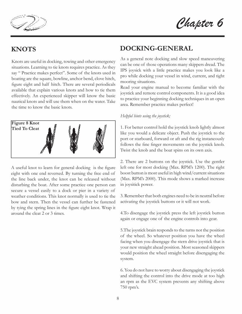
8
Chapter 6
KNOTS
Knots are useful in docking, towing and other emergency situations. Learning to tie knots requires practice. As they say “ Practice makes perfect”. Some of the knots used in boating are the square, bowline, anchor bend, clove hitch, fi gure eight and half hitch. There are several periodicals available that explain various knots and how to tie them effectively. An experienced skipper will know the basic nautical knots and will use them when on the water. Take the time to know the basic knots.
Figure 8 KnotTied To Cleat
A useful knot to learn for general docking is the fi gure eight with one end reversed. By turning the free end of the line back under, the knot can be released without disturbing the boat. After some practice one person can secure a vessel easily to a dock or pier in a variety of weather conditions. This knot normally is used to tie the bow and stern. Then the vessel can further be fastened by tying the spring lines in the fi gure eight knot. Wrap it around the cleat 2 or 3 times.
DOCKING-GENERALAs a general note docking and slow speed maneuvering can be one of those operations many skippers dread. The IPS joysick with a little practice makes you look like a pro while docking your vessel in wind, current, and tight mooring situations.Read your engine manual to become familiar with the joystick and remote control components. It is a good idea to practice your beginning docking techniques in an open area. Remember practice makes perfect!
Helpful hints using the joystick;
1. For better control hold the joystick knob lightly almost like you would a delicate object. Push the joystick to the port or starboard, forward or aft and the rig instaneously follows the fi ne fi nger movements on the joystick knob. Twist the knob and the boat spins on its own axis.
2. There are 2 buttons on the joystick. Use the gentler left one for most docking (Max. RPM’s 1200). The right boost button is most useful in high wind/current situations (Max. RPM’s 2000). This mode shows a marked increase in joysitick power.
3. Remember that both engines need to be in neutral before activating the joystick buttons or it will not work.
4.To disengage the joystick press the left joystick button again or engage one of the engine controls into gear.
5.The joystick brain responds to the turns not the position of the wheel. So whatever position you have the wheel facing when you disengage the stern drive joystick that is your new straight ahead position. Most seasoned skippers would position the wheel straight before disengaging the system.
6. You do not have to worry about disengaging the joystick and shifting the control into the drive mode at too high an rpm as the EVC system prevents any shifting above 750 rpm’s.

9
Vessel Operation
ANCHORINGYour Regal yacht features a stainless s t e e l p l ow t y p e anchor. The anchor will set quickly in a variety of bottoms because of its unique shank profile and ballasted tip. It is a high holding type anchor made from high grade manganese steel and stainless steel for maximum
tensile strength. The anchor weight is 55 pound or (25) kg. Anchoring is easier with another person on board. First be certain that the line for the anchor is properly attached, to avoid losing the anchor and anchor line overboard.For more effi ciency, a 25’ length of galvanized chain has been added to the rode length. The chain will stand up to the abrasion of sand, rock, or mud on the bottom much better than a nylon line. Being galvanized the chain will resist corrosion. Approximately 175’ of 3 strand nylon line has been added to ensure a adequate scope in different depths and weather situations. The nylon will stretch under a heavy strain cushioning the impact of waves or wind on both the boat and the anchor.To anchor, select an area preferably with a fl at bottom. Mud, sandy clay and fi rm stand afford the best bottoms for anchoring. Grassy bottoms often resist the anchor taking hold and end up pulling out grass and roots. Contrary to modern belief, you do not anchor while the boat is making headway, or moving forward. In fact, the bow of the boat should be brought slowly backward, while releasing the anchor until it hits the bottom. To “snub the line” means to stop its outward “pay” or movement. Usually the length of anchor line used should be 5 to 10 times the depth of the water depending on weather conditions. This ratio is called the “scope”; the minimum scope under average conditions is 7 or 8:1. If the scope is too short the anchor’s effi ciency is diminished. A longer scope cushions the shock load on the entire system.
Once a scope is determined sometimes it is diffi cult to know how much line to let out to reach the desired scope especially at night. One way to mark an anchor line that will identify the amount of line is to paint wide and narrow bands from about 50’ to 150’ in 10’ intervals. The wide bands equal 50’ and each narrow band would equal 10’. Distinguish each 50’ band with a different color paint. This can be done with “see in the dark” paint. Simply tape each length for the appropriate band before painting it. After you have anchored, check your position with landmarks if possible. You need to continue to monitor these landmarks to make sure you are not drifting. Since anchoring can also be an emergency procedure, the anchor and line should be readily accessible. Check anchor locker to ensure an untangled anchor line.Once anchored the anchor line must be secured to a strong tie such as a cleat. Do not rely on the windlass brake to carry the anchor rode load.Use a series of full turns and half-hitches around the cleat horn to prevent any line slippage or jamming. This is important as the scope may need to be adjusted over a period of time and you need swift access to the line.For increased holding power in windy conditions, twoanchors are sometimes set. If your primary anchor drags, you can run out your secondary anchor without picking up the primary one. The important thing is to lay them out at an angle. When setting two anchors, make sure they are fastened to separate strong ties such as cleats. This is done in case you need to adjust one later so the line must be accessible.
Note: In times of high waves a buoy on the rode works as a shock absorber and allows the vessel’s bow to ride the wave crests without large strains being transmitted to the set anchor. These plastic foam buoys can be purchased at boating retail outlets.

10
Chapter 6
ADMIRALTY LAW
The Admiralty law sometimes referred to as the salvage law was founded primarily on English law fundamentals and basically says that a vessel distressed, in danger of fl ounder, if rendered assistance from a towing company or private agency, can be forced to relinquish a portion of the vessels’ worth for the assistance received.
TOWING
In case you fi nd yourself aground or in need of a tow, or should you want to tow another vessel, keep in mind that you never use deck hardware or cleats to secure lines for towing!Deck hardware is intended for mooring and anchoring, and is not designed to withstand the strain and pull of towing. Rather than tie the line to your cleats on deck, it is suggested that you tie a bridle by passing a line completely around the hull of your boat to avoid structural damage. When towing, always stand clear of a taut line, as any type of line breaking under stress can be extremely dangerous. The preferred line for towing is double-braided nylon, as it has suffi cient elasticity to cushion shock loads. Move slowly and cautiously.
AVOID DEATH OR SERIOUS BODILY INJURY!
DO NOT USE DECK HARDWARE
INCLUDING CLEATS FOR TOWING
OR LIFTING PURPOSES.
DANGER!
IN THE EVENT YOUR VESSEL
IS IN DISTRESS
PRIOR TO ALLOWING
ANY TOWING COMPANY
OR PRIVATE AGENCY THE RIGHT
TO PASS A LINE TO YOUR VESSEL,
BE SURE TO ESTABLISH THAT YOU
DO NOT AGREE TO ANY SALVAGE RIGHTS.
ESTABLISH WITH THE CAPTAIN
OR OPERATOR
THAT YOU WISH TO BE ASSISTED
IN A CONTRACT BASIS
AND ESTABLISH A PRICE.
OF COURSE IN CERTAIN SITUATIONS,
YOU MAY NOT HAVE THIS OPTION.
USE YOUR BEST JUDGEMENT!
NOTICE

11
Vessel Operation
EMERGENCIES
Always be ready to help others on the water if possible, but do not take any unnecessary risks. Use equipment to save a life, but do not risk a life to save equipment. Consult earlier information in this manual concerning accidents, etc. Also, read other literature concerning on the water emergencies. Be alert and prepared!
FIRE
Fire aboard a vessel can spread quickly and can cause tremendous alarm among everyone. Most fi res can be prevented by keeping the bilge free from oil and debris. Keep all equipment stowed and maintained in working order. Carry backup fire extinguishers on board. If something becomes a possible fi re hazard, remove that possibility at once. Never use water on gasoline, oil or electrical fi res. When you dump water on an electrical fi re you can be shocked since water conducts electricity.Follow these instructions if a fi re breaks out:
1. Fit everyone aboard with a life jacket. Turn off the ignition switch.
2. Try to keep the fi re downwind. If the fi re is to the stern, head the bow toward the wind. If forward, put the stern to the wind.
3. If the engine should catch fi re, shut off the fuel supply Usually there is a fuel tank access that you can crimp the fuel feed line.
4. Use a hand fire extinguisher. Make sure to point it at the base of the flames. Use short bursts and sweep the extinguisher side to side. Remember: (A 4 pound extinguisher discharges in approximately 20
seconds)These actions help prevent the fi re from spreading to other parts of the boat. You can extinguish fi res quickly if you act swiftly. Have a plan of action in motion in case a fi re breaks out.
FIRST AID
Knowing fi rst aid can save lives. A fi rst aid kit and the ability to use it are important ingredients for the safety of a skippers’ passengers, crew and vessel. Having confi dence and competence in handling medical emergencies on board is a must for the skipper. Invest your time in a fi rst aid course available at the American Red Cross.
If someone is seriously injured have someone call for help while the injured person is being attended.Check for possible danger signs; loss of breathing, unconsciousness, severe bleeding and heartbeat. If you determine the individual is not breathing or unconscious place the victim on their back on a hard surface and do the following:
1. If unconscious, open the airway. Neck lift, head lift or chin head lift.
2. If not breathing, begin artifi cial breathing. Pinch the nose. Give 4 quick breaths. If airway is blocked, try back blows, abdominal or chest thrusts and fi nger probe until airway is open.
3. Check for pulse. Begin artifi cial circulation. Depress sternum. Fifteen compressions rate 80 per minute. 2 quick breaths. Continue uninterrupted until advanced medical support is available.
CPR (BASIC LIFE SUPPORT)

12
Chapter 6
HYPOTHERMIA
Hypothermia is a condition where the body temperature decreases because the body can’t generate enough heat to maintain its normal temperature. It can be serious and usually occurs where victims have been immersed in water (under 68 degrees) for periods of time. If you encounter a possible hypothermia victim call for help on the radio and get the person out of the water.Symptoms are:
1. Shivering that if condition is advanced may stop.
2. Confusion, clumsiness or slurred speech.
3. Rigid muscles.
4. Semiconscious to unconscious.
Treat hypothermia by the following:
Remove wet clothing.
Monitor the victim’s pulse and breathing.
Rapidly apply heat to the body core by using blankets, naked bodies or warm water.
Do not give the person any food or drink.
Do not warm the arms and legs. Warming of these extremities can be fatal.
Follow up immediately with medical authorities!

13
Vessel Operation
CALIFORNIA AIR RESOURCE BOARD (CARB) LABEL
Your Regal boat may have a star shaped label affi xed to the bow port hullside. It is located at the front of the state registration numbers. This label is part of the California Air Resource Board (Carb) SD/I rule. If your boat is op-erated in the state of California and/or bordering waters, this label MUST remain intact. The label shows that the engine installed as original equipment meets a currently approved California state regulatory emission level. See the example below which shows the current California ultra low 3 star label.
Proposition 65 relates to the state of California and is an additional requirement added to their Safe Drinking & Toxic Enforcement Act of 1986. Prop 65 basically sum-marized states that: “No person in the course of doing business shall knowingly discharge or release a chemical known to the state to cause cancer or reproductive toxic-ity into water or onto land where such chemical passes or probably will pass into any source of drinking water ....” and it goes on to say “ no person in the course of doing business shall knowingly and intentionally expose any individual to a chemical known to the state to cause cancer or reproductive toxicity without fi rst giving clear and reasonable warning to such individual .....” For more information, contact the California Offi ce of Environmental Health Hazard Assessment at 916-445-6900 or http://www.oehha.ca.gov/prop65.html.
CARB LABEL
CALIFORNIA PROP 65
WARNING!A wide variety of components used on this vessel contain or emit chemicals known to the State of California to cause cancer and birth defects and other reproductive harm.
EXAMPLES INCLUDE:* Engine and generator exhaust* Engine and generator fuel, and other liquids such as coolants and oil, especially used motor oil* Cooking fuels*Cleaners, paints, substances used for vessel repair* Waste materials that result from wear of vessel components* Lead from battery terminals and from other sources such as ballast or fi shing sinkers
TO AVOID HARM:* Keep away from engine, generator, and cooking fuel exhaust fumes* Wash areas thoroughly with soap & water after handling the substances above

14
Chapter 6FUEL SPILLAGE
The federal water pollution control act prohibits the dis-charge of oil or oil waste (such as from the sump bilge pump) into or upon the navigable waters of the United States or the waters of the contiguous zone. Violators are subject to substantial civil fi nes and criminal sanctions.A placard is normally found inside the engine hatch area or in the sump warning of overboard discharge of oil or oily waste.
ENVIRONMENTAL AWARENESS
There are numerous vessels operating on our waterways on a daily basis. Each boat has as impact on our environment. Boat operation habits, marine sanitation, and maintenance all play a role in a delicate battle to keep the ecosystem clean. Each of us has a role in doing our part as a environmentally conscious skipper to conserve our waterways.The National Marine Manufacturer’s Asscociation lists their top ten of Eco-Boating Practices as follows:
1. Observe all regulatory agency policies regarding marine toilets.2. If equipped with a holding tank, use marina pump-out facilities.3. If used, make sure bottom paints are legal and ecosystem friendly.4. Use only biodegradable cleaning agents.5. Dispose of all garbage and liter on shore properly, not on the water. 6. Don’t top off fuel tanks. Leave expansion room. Clean up spills.7. Watch your wake and propeller wash.8. Make sure your engines are well tuned and maintained.9. Control your bilge water.10. When fishing, practice the “catch and release” principle.

1
Auxiliary Equipment Operation
AUXILIARY COMPONENTS
OVERVIEW
In addition to the main components and systems reviewed in Chapter 4 there are other auxiliary equipment compo-nents outlined here. To locate more detailed information for the auxiliary components refer to the appropriate manufacturers owner’s manual found in the owner’s infor-mation packet. Also, further updated information may be available on the internet by using the proper name of the component and the Goggle® search vehicle.
Note: Equipment or vendors may change during a boat’s life cycle as we are constantly upgrading our product line. Regal Marine Indus-tries, Inc. retains the right to change vendors, equipment, specifi cations, component location, and other technical data at any time.

2
Chapter 7
Exterior Equipment Component Page
Antennae 27Bilge Pump/Float Switch 28Bottom Paint 39Camera Monitoring System 30Compass 31Cool Cockpit 32Door-Transom 33 Electronics-General 34Fire Extinguisher-Automatic 35Generator 37Hard Top 38Hard Top Enclosure 38Hatch-Engine 39Heater-Hot Water 43High Water Alarm 44 Markers-For Slings 45Odor In-Line Waste Filter 50Oil Change System 46Overboard Discharge Pump 50Pressure Pump-Fresh Water 51Satellite Radio 52 Shower-Transom 53Sirius Marine Weather 54Spotlight 56Sunpad-Aft Cockpit 57Sunpads-Fwd. Deck 57Swim Ladder 58Swim Platform 59Underwater Lighting 61
Interior Equipment Component Page
Carbon Monoxide Detector 3Door-Companionway 4Grey Water System 5Hatches 6Lighting-Cabin 7Monitor-Water/Waste 10Portlights 11Range/Stove 12Refrigerator 13 Salon Furniture-Dinette 15Seat-Helm 16TV-LCD Monitor Precautions 17 Vacuum System 18Washer-Dryer Combo 20

3
Auxiliary Equipment Operation
CARBON MONOXIDE DETECTORS
Carbon monoxide known as CO is indeed the silent killer. It is a by-product of combustion. CO is invisible, taste-less, odorless and is produced by all internal combustion engines, heating and cooking appliances. The most common forms of CO on board vessels are pet-rol engines/generators and if applicable, propane heating and cooking devices. Note: Even though your vessels propulsion system is diesel based follow the CO precautions. Also, remember that a vessel moored next to you may be a CO poison contributor. Never operate these devices when people are sleeping. A slight amount of CO in the human body over several hours causes headaches, nausea and symptoms close to food poisoning, motion sickness or fl u. High concentra-tions can be fatal within minutes.
HOW THE SYSTEM WORKS
The CO detector uses a mini computer to measure and ac-cumulate CO levels. Using the principle of “time weighted averaging” the detector monitors CO concentrations, tem-perature, humidity and time to calculate COHb levels. To explain COHb, our bodies prefer to absorb CO to oxygen and COHb is the absorbed ratio stated in a percent. If the detector senses high levels of CO the alarm will sound in a few minutes. If lower levels are sensed, the detector will accumulate the data and sound an alarm when the appropriate level is reached. Read and understand the CO owner’s manual in the information pouch.
To turn the CO detector system on:
1. Notice the CO breaker on the 12 volt main DC panel. It must be turned off in a two-step sequence. This is for safety purposes. The system should be always left ON. You must fl ip back the switch cover before you are able to deactivate the breaker.The CO circuitry works to its best performance when continually activated plus it accords advanced warning when entering an area high in CO.
3. The test cycle should be activated frequently. Simply press the button. When it is released, the (top) power indicator will flash off and the lower indicator light will flash on. Then, the lower indica-tor will fl ash off and the upper indicator light will come back on.The top indicator light be-ing on solid green indicates normal operation. Refer to
the CO detectors owner’s manual for an explanation of the test cycle indicators.
4. When an alarm sounds take action immediately. The danger alarm indicator fl ashes red and the horn beeps 4 times, pauses and repeats the cycle. This indicates a rate of 10% COHb has been reached.
a. Operate reset/silence button.b. Call your emergency services (911)c. Immediately move to fresh air. Do not re-enter the vessel. until emergency personnel have arrived, aired the vessel out and the alarm is in a normal condition.d. After following steps a-c and your alarm reactivates within a 24-hour period call a qualifi ed technician to inspect the vessel. Note that the CO detector will clear when the CO concentration has dropped below 70 ppm.
CO DETECTOR
2. When power is applied to the detector, the power in-dicator (top) will fl ash on and off, followed by the (red) lower alarm indicator fl ashing off and on as part of a 8-14 minute warm-up period. The green (top) power indicator will indicate a solid green when the unit has reached cor-rect operating temperature. Never operate a cooking device with the canvas up or the cabin door completely closed to prevent CO concentration build-up
INTERIOR EQUIPMENT

4
Chapter 7
DOOR-COMPANIONWAY
Keep the cabin door se-cured closed when the boat is moving. When at mooring, the cabin entry door can be held open by sliding the door and securing it open with the door stop. This will prohibit the door from accidentally closing, a great safety feature. The built-in screen door func-tions independently on its own track.
Door Lock
Screen Door
With the screen door closed and the hatch screens in place cross venti lat ion can be achieved along with the ability to keep insects out of the cabin.Periodically, remove any accumulated door track debris and lu-bricate the tracks to keep the doors sliding freely.
If installed, the grey water system equipment collects all used water exiting from the shower sump pumps along with the galley and head sinks. The used water is stored in the ship’s holding (waste) tank. This option is used in various locals where it is illegal to pump “grey” shower and sink water overboard. The automatic fl oat switch pumps grey water to the holding tank. Normally it would not require any special service unless there was blockage somewhere in the system or a hose leak developed in the system. Since more liquid in the form of grey water is being returned to the holding tank pay closer attention to the waste monitor panel. The holding (waste) tank may need to be pumped out more frequently.
GREY WATER SYSTEM

5
Auxiliary Equipment OperationHATCHES
Most deck hatches feature a locked position. To lock the hatch fi rst grab the handle and turn it so it engages the side of the seal ring as shown. Push the lock mechanism to engage the handle in the locked position.To unlock the hatch pull the handle away from the seal ring (in line with adjuster) or 90 degrees from the locked position. To open the hatch make sure the hatch is unlocked. Then push the rod up and lock at desired angle by turning the adjuster. A screen is provided for cross ventilation and to protect against insects. Secure the screen by turning the tabs at a 90 degree angle to the screen framework.
Hatch Shown In Locked Position
LatchLock
Adjuster

6
Chapter 7LIGHTING-GENERAL
Your vessel features various styles of lighting such as overhead, hanging locker, reading and fl orescent types. Each lighting fi xture requires specifi c bulb types and re-placement procedures. Read and understand the following warning.
Later overhead lights use LED technology which is known for clear visibility, long service life, and energy savings. Note: These later LED lights will feel much cooler than the previ-ous halogen type.
AVOID SERIOUS INJURY!EARLIER HALOGEN & XENON LIGHT BULBS
DEVELOP EXTREMELY HOT TEMPERATURES.
NEVER REMOVE A HOT LIGHT BULB SINCE IT COULD CAUSE SKIN BURNS. WAIT FOR THE BULB TO COOL
BEFORE ATTEMPTING TO REMOVE IT.
WARNING!
Note: The bulbs listed in the following pages can be ordered through a Regal dealer or may be available at speciality lighting or box stores. When changing the ear-lier halogen light bulbs never touch the bulb surface with your fi ngers as premature burn out can occur due to oil on the skin touching the bulb surface. Handle bulbs only from the ends.
Insert Here ToLoosen Cover
To change the earlier halogen overhead light bulb follow these steps:
Using a sharp object such as a small slotted screwdriver, slide it between the lens cover and the light base.
Pull down on the lens cover to access the bulb.
Remove the defective bulb.
Replace the bulb with a 12 volt, #10WXM halogen type.
Line up the space in the lens cover/body with the notched area of the light base.
Push the prongs on the lens cover/body upward until they seat into the light base.
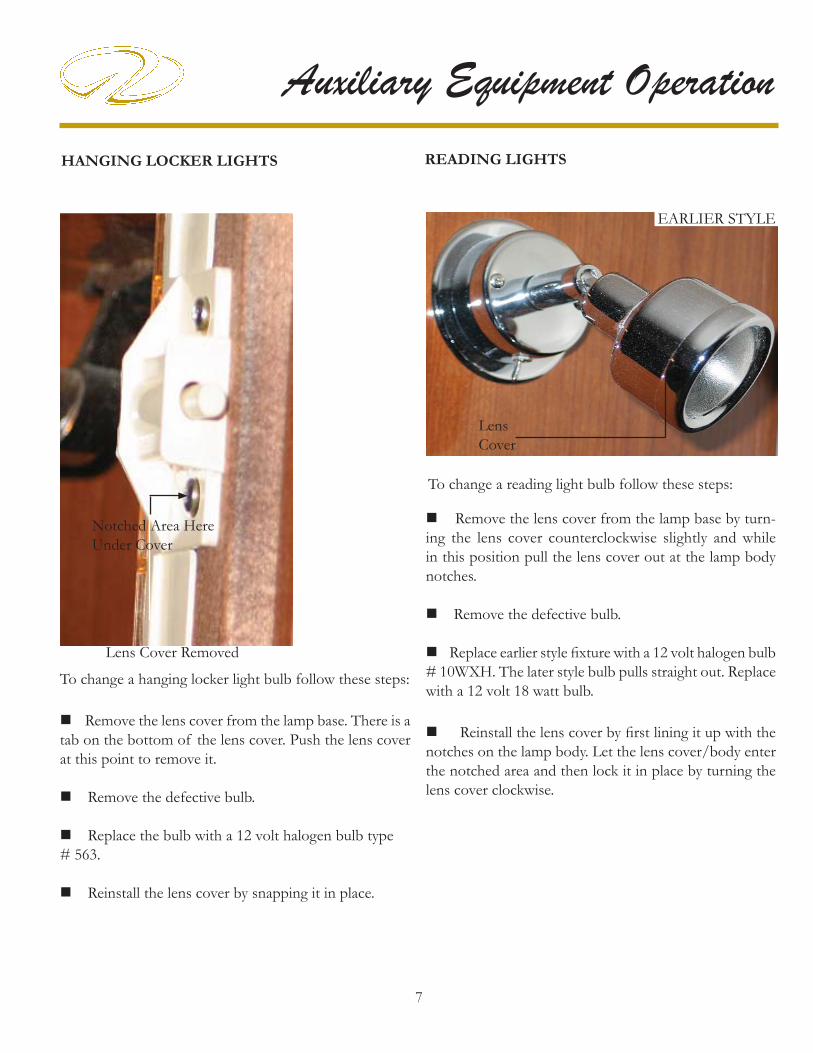
7
Auxiliary Equipment Operation
To change a hanging locker light bulb follow these steps:
Remove the lens cover from the lamp base. There is a tab on the bottom of the lens cover. Push the lens cover at this point to remove it.
Remove the defective bulb.
Replace the bulb with a 12 volt halogen bulb type # 563.
Reinstall the lens cover by snapping it in place.
HANGING LOCKER LIGHTS READING LIGHTS
To change a reading light bulb follow these steps:
Remove the lens cover from the lamp base by turn-ing the lens cover counterclockwise slightly and while in this position pull the lens cover out at the lamp body notches.
Remove the defective bulb.
Replace earlier style fi xture with a 12 volt halogen bulb # 10WXH. The later style bulb pulls straight out. Replace with a 12 volt 18 watt bulb.
Reinstall the lens cover by fi rst lining it up with the notches on the lamp body. Let the lens cover/body enter the notched area and then lock it in place by turning the lens cover clockwise.
LensCover
EARLIER STYLE
Lens Cover Removed
Notched Area Here Under Cover
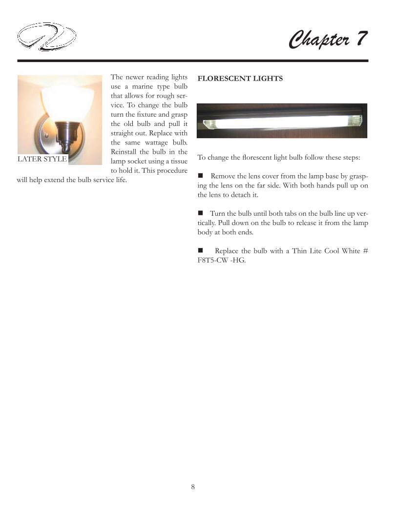
8
Chapter 7FLORESCENT LIGHTS
To change the fl orescent light bulb follow these steps:
Remove the lens cover from the lamp base by grasp-ing the lens on the far side. With both hands pull up on the lens to detach it.
Turn the bulb until both tabs on the bulb line up ver-tically. Pull down on the bulb to release it from the lamp body at both ends.
Replace the bulb with a Thin Lite Cool White # F8T5-CW -HG.
LATER STYLE
The newer reading lights use a marine type bulb that allows for rough ser-vice. To change the bulb turn the fi xture and grasp the old bulb and pull it straight out. Replace with the same wattage bulb. Reinstall the bulb in the lamp socket using a tissue to hold it. This procedure
will help extend the bulb service life.

9
Auxiliary Equipment Operation
To read either the fresh water or waste water monitor panel the breaker on the main DC panel must be activated.The monitor is normally located inside the ship’s AC/DC cabinet or may be located behind the starboard picture window on a trim panel.The fresh water monitor displays the amount of potable water in the system. There are sensors located in the water tank that send a signal to the display panel when activated. Press the top portion of the toggle switch and read the gauge display.The waste portion of the display shows the amount of waste water in the holding tank. There are sensors located in the waste tank that send a signal to the display panel when activated. Press the bottom portion of the toggle switch and read the gauge display. This portion of the system needs to be monitored peri-odically to prevent the system from being over full which could cause equipment damage and/or a possible leak in the vessel.If the waste system is determined to be full it can be emptied by connecting a marina pump-out hose to the waste fi tting located on the deck. The pump out device will actually remove the waste much like a vacuum cleaner.This is the easiest way to eliminate the vessel’s waste and be environmentally friendly while performing the task.An alternative method which can be used in International wa-ters only is to pump the waste overboard using the waste seacock.
MONITOR-WATER/WASTE
FRESH WATER & WASTE MONITOR
MaceratorKey Switch
Notice the key switch portion of the monitor. The key switch controls an overboard discharge pump (macerator) which can grind up the waste and send it through the hull bottom. Make sure the waste seacock is open and you are legal to pump overboard. Turn the macerator breaker on and then energize the monitor panel key switch. Be sure to turn the seacock off and secure it with a tie wrap after the pump-out cycle is completed as you can be fi ned if authorities fi nd the seacock in an unlocked position.

10
Chapter 7PORTLIGHTS
Portlights provide cabin cross ventilation in addition to light. To open, turn the latches port or starboard until the portlight cover clears. Lift the black handle to control the amount of fresh air. To close, shut the portlight cover and turn the latches up to provide a seal. A screen is provided for insect protection.
Shown In Closed Position Turn LatchesTo Open/Close

11
Auxiliary Equipment OperationRANGE/STOVE
AVOID SERIOUS INJURY!NEVER ALLOW SMALL CHILDREN
NEAR THE COOK TOP!
WARNING!
AVOID SERIOUS INJURY!OBSERVE ALL SAFETY INSTRUCTIONS
WHILE USING THE COOK TOP.
WARNING!Twin Burners
RANGE TOP CUT-OUT SWITCH
A cut-out switch shuts the power to the stove burners should a cooking fi re develop. When the stove cover is installed over the stove the burner power is then inter-rupted. At that point the stove breaker on the main AC panel should be turned to the “off ” position. Always have the correct type portable fi re extinguisher ready when cooking aboard the vessel.
Burner Knobs
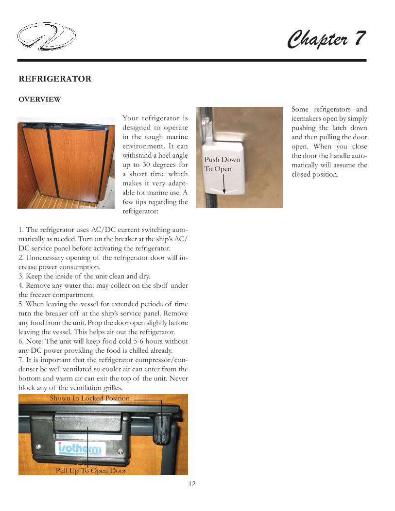
12
Chapter 7
REFRIGERATOR
OVERVIEW
Your refrigerator is designed to operate in the tough marine environment. It can withstand a heel angle up to 30 degrees for a short time which makes it very adapt-able for marine use. A few tips regarding the refrigerator:
1. The refrigerator uses AC/DC current switching auto-matically as needed. Turn on the breaker at the ship’s AC/DC service panel before activating the refrigerator.2. Unnecessary opening of the refrigerator door will in-crease power consumption.3. Keep the inside of the unit clean and dry. 4. Remove any water that may collect on the shelf under the freezer compartment.5. When leaving the vessel for extended periods of time turn the breaker off at the ship’s service panel. Remove any food from the unit. Prop the door open slightly before leaving the vessel. This helps air out the refrigerator.6. Note: The unit will keep food cold 5-6 hours without any DC power providing the food is chilled already.7. It is important that the refrigerator compressor/con-denser be well ventilated so cooler air can enter from the bottom and warm air can exit the top of the unit. Never block any of the ventilation grilles.
Shown In Locked Position
Pull Up To Open Door
Some refrigerators and icemakers open by simply pushing the latch down and then pulling the door open. When you close the door the handle auto-matically will assume the closed position.
Push Down To Open

13
Auxiliary Equipment OperationNormal Refrigerator Operating Sounds
Your refrigerator/icemaker combo features rigid foam insulated cabinets to provide high thermal efficiency and maximum sound reduction for its internal working components. In spite of this, the unit still may make some unfamiliar sounds.Normal operating sounds may be more noticeable because of the unit’s environment. Hard surfaces such as fi berglass fl oors have a tendency to refl ect normal appliance operating noises.Common refrigeration components, and a brief description of the normal operating sounds they make, are listed below. Note: Your unit may not contain all of the components listed.
Compressor- The compressor makes a humming or pulsing sound during normal operation.
Evaporator- Refrigerant fl owing through this unit may sound like boiling water.
Condenser Fan- May hear air moving through it.
Water Valve- At each cycle, a buzzing is heard.
Your refrigerator is equipped with a manually controlled infi nitely-variable thermostat. Turn the thermostat clockwise to lower the temperature and counterclockwise to raise the temperature and to activate the on-off switch. A slight spring resistance is noticeable at the on-off switch.
TEMPERATURE SETTING
DEFROSTING
The refrigerator requires defrosting when the frost layer is around 1/8”. To defrost do the following:
1. Turn the thermostat off.
2. Store the food and beverages from the refrigerator in an iced down cooler.
3. Do not use sharp metal objects to remove the accumu-lated ice. Let the refrigerator deice under normal cabin temperatures.
4. Restart the refrigerator after it is completely defrosted.Be sure to clean and dry the unit.
5. Empty the drip tray below the freezer compartment as often as needed in the defrosting cycle.
Typical Thermostat

14
Chapter 7
During extended periods of non-use take the following precautions.
1. Turn off the icemaker breaker at the ship’s AC distribution panel.
2. Turn the unit to the “OFF” position at the power valve.
3. Raise the bin arm to turn the icemaker off.
4. Empty the refrigerator of all items. Clean the interior of the unit with a mild non-abrasive detergent and warm water solution applied with a soft sponge or soft cloth. Rinse with warm water and a soft sponge. For rust spots use Bon-Ami®or Barkeepers Friend Cleanser®
5. Prop the door open. The unit will manually defrost.
Periods Of Non-Use

15
Auxiliary Equipment OperationSALON TABLE TYPICAL
The salon-dinette table is designed to be moved as needed to provide dining and lounging capabilities. To set up the table:
1. Set the table base where you want it.
2. For ease of installation set the table on the sofa with the table pedestal support facing up. Turn the upper table leg lock counterclockwise until the gap is large enough to accommodate the table leg diameter.
3. Install the table leg in the table pedestal support hole. Tighten the leg lock until secure.
5. Insert the table and table leg as an assembly into the fl oor receiver.
Table Leg
Table Pedestal Support
SALON-DINETTE TABLE ADJUSTMENTS
Upper Table LegLock
Receiver

16
Chapter 7
SEAT-HELM
The helm seat features an electric hydraulic mechanism which moves the captiain’s seat fore-aft and up-down to accommodate different body types and cruising options.The helm seat features a leaning post to gain extra height or additional standing room at the helm when maneuver-ing in close quarters. There is a dual set of toggle style switches to the starboard side of the helm. The arrows on the switches depict the function. See the illustration on the right.To add seat height using the leaning bolster lift the front of the helm seat upward. This permits the leaning bolster to rotate upward until fully extended. See the illustration below.
Flip Up Legs And Pull Latch For Increased Stand-Up Height
Helm Seat Switches
CAPTAIN’S SEAT SWITCHES
SEAT-HELM-USING TEAK PLATFORM
Flip Front CushionUp For IncreasedStanding Room
Latch

17
Auxiliary Equipment Operation
CAUTION!RISK OF EQUIPMENT DAMAGE!
IN FREEZING CLIMATES
REMOVE THE TELEVISION SET
FROM THE VESSEL.
The following safety information applies to all LCD fl at screen television monitors. Refer to the antenna switch information in Chapter 4 for the proper connection de-pending where the vessel is moored.
TV (LCD) MONITOR PRECAUTIONS
CAUTION!RISK OF ELECTRICAL SHOCK!
DO NOT REMOVE COVER
AT TELEVISION REAR.
NO USER-SERVICEABLE PARTS INSIDE.
REFER SERVICING
TO QUALIFIED PERSONNEL ONLY.
SAFETY INSTRUCTIONS
NOTICEWHEN LEFT FOR EXTENDED PERIODS
TURN THE TELEVISION BREAKERTO THE OFF POSITION
TO HELP PREVENTPOWER SURGES OR LIGHTNING
DAMAGE.
NOTICETHE FLUORESCENT LAMP USED IN
THIS TELEVISION CONTAINS A SMALLAMOUNT OF MERCURY.
DISPOSE OF THIS PRODUCT IN AN ENVIRONMENTAL FRIENDLY
MANNER USING LOCAL GUIDELINES.
NOTICEIF TV FEELS COLD TO THE TOUCHTHERE MAY BE A SMALL FLICKER
WHEN IT IS ACTIVATED. THIS IS NORMAL.

18
Chapter 7
VACUUM CLEANER SYSTEM TYPICAL
The vacuum system is located in theaft stateroom under the forward bunk. Included is a netted bag of hoses and various vacuum attachments.
SAFETY WARNINGS
1. This is a dry vacuum system. Do not use on wet sur-faces.
2. Never operate the vacuum without fi lters and bags in place.
3. Use careful monitoring when children are around. Do not let the vacuum cleaner be used as a toy.
4. Do not try to repair the vacuum as the unit is sealed. Return the unit to InterVac or an authorized reparir center for proper repairs.
5. Use only as described in this manual. Use only factory attachments and bags.
6. Do not use with any blocked openings. When the sec-ondary fi lter becomes dirty, rinse in warm water or replace the fi lter. Filters must be completely dry before using.
7. Never drop or put any object into any opening.
8. Turn off the accessory breaker at the ship’s AC panel to deactivate the vacuum cleaner.
9. Keep all body parts and clothing away from all moving parts.
10. Do not pick up anything that is burning or smoking such as cigarettes, matches, hot ashes or sharp objects. Do not use without dust bag or fi lters in place.
11. Do not attempt to operate the unit with a wet hose.
12. Do not store objects close to the vacuum unit.
13. Do not pick up fl ammable or combustible liquids such as gasoline, or use in areas where they might be present such as the bilge.
14. Do not step on the hose, nozzles or pull hard on the hose.
OPERATION
1. To operate the vacuum, the accessory breaker at the main ship’s main AC panel must be turned to the “ON” posi-tion.
2. Lift the inlet cover on the vacuum unit.
3. Insert the hose cuff (one with the metal band) with a slight twist and the vacuum cleaner should start.
4. To remove, turn hose in either direction while pulling the hose toward you and the vacuum cleaner will stop.
Exhaust Filter
Door
Inlet Valve/Cover
Dust Bag
Vacuum UnitCase/Motor
Note:If the motor stops the thermal protector on the unit will reset automatically after about 1/2 hour. This is normal for the vacuum cleaner.

19
Auxiliary Equipment Operation
Replacing Exhaust Filter
To RemovePinch Filter InThe Middle &Pull Out
To Replace:Pinch In TheMiddle & SlideIn One Side First
If The Motor Stops Suddenly:
Insert Hose Cuff Here
1. The most common cause is a clogged hose. Try to unclog the hose with a long object or by shaking the hose until the debris falls out.
2. The bag is overfi lled and fi ne dust has clogged the bag.
3. The vacuum cleaning tools are clogged.
4. The motor (exhaust) fi lter is dirty and should be cleaned or replaced.
5. While the vacuum cleaner is being used keep the cushion up to provide additional air to the unit. This will help the unit from shutting down.
Insert Hose Cuff Here

20
Chapter 7WASHER/DRYER COMBO (46SC)

21
Auxiliary Equipment Operation
WASHER/DRYER FEATURES

22
Chapter 7
The optional washer-d r y e r c o m b o w a s developed for longevity and carefree service. The unit automatically switches from washer to dryer cycles.T he un i t ope ra t e s on 120 volts, single phase AC current and draws approximately 12 amperes and 1300 watts. A 15 amp breaker protects the circuitry.
Wash Only Procedure
1. Turn on the washer-dryer breaker on the AC distribution panel.
2. Ensure the door is completely shut.
3. Ensure that the hot and cold water supply is turned to the “on”position. (Remember to turn on the hot water heater an hour or so before washing if you want a hot water wash).
4. The Program Selector Knob (A) needs to be positioned on one of the “Reset” positions.
5. The ON/OFF button (I) is in the OFF position.
6. Select the program according to the type of garments you are washing. Refer to the “Guide To Wash Programs”.
7. Turn the PROGRAM SELECTOR knob (A) clockwise until the selected program lines up with the knob mark.
8. Turn the WASH TEMP. knob (C) to the desired wash temperature for the load.
9. If needed, use buttons E, F, G, or H to run a special program. If these buttons are not being used, leave them in the OFF or out position. Note: Should you wish to interrupt a program in progress or set a new one, advance the PROGRAM SELECTOR KNOB (A) to a “reset” position and wait 5 seconds. Icon light will fl ash slowly, then the appliance will be turned off. At the end of the wash cycle:
• The STATUS/DOOR LOCK lamp (L) will quickly fl ash for up to 1-2 minutes to indicate the wash cycle is fi nished, but the door is still locked. The light will fl ash slowly when the door can be safely opened.
• When the STATUS/DOOR LOCK (L) fl ashes very slowly, turn the washer-dryer OFF by pressing the ON/OFF button (I) again.
• Open the washer-dryer door and remove the cleaned laundry.
• After removing the laundry, leave the door open if possible to allow fresh air circulation inside the drum to avoid formation of bad odors.
For more information refer to the drawings on the following pages.

23
Auxiliary Equipment Operation
Setting delay start
Use the DELAY START option on the washer-dryer to delay the start of any wash program by 12, 9, 3, or 1 hour.
• With the washer-dryer power OFF, turn the PROGRAM SELECTOR KNOB (A) clockwise to one of the 4 delay start positions (12, 9, 3, or 1).
• Press the ON/OFF button (I). The STATUS/DOOR LOCK lamp will fl ash slowly for 5 seconds and then stays lit to indicate that the delay time has been accepted. Now you can turn the knob clockwise to the program you desire.
• The STATUS/DOOR LOCK lamp (L) has a particular fl ashing motion (2 seconds on and 4 seconds off) to indicate that a delayed start has been set. During this phase, you can open the appliance door and change the washing load.Note: After the wash cycle has been set and accepted by the washer-dryer turning the knob will have no affect except when it is on the RESET position.
Helpful Hints:
1. The washer features a water level sensor control system that ensures the correct level of water is pumped into the machine for the load size.
2. Use one of the “EXPRESS” wash cycles to wash smaller loads of lightly soiled cotton heavy duty or permanent press fabrics in less time.
3. The EASY IRON button uses specifi cally studied wash motions to respect fabrics in the best possible way. During the rinse phase, it introduces more water and the spin cycle is shorter with a reduced speed, thus producing more outstretched fabrics for easier ironing (See “Understanding the control panel” for more information).
NOTICEAVOID EQUIPMENT DAMAGE!KEEP THE WASHER-DRYER
AND CABINET DOORS CLOSED WHILE THE VESSEL IS IN MOTION. USE THE WASHER-DRYER ONLYWHEN THE VESSEL IS STOPPED.

24
Chapter 7
UNDERSTANDING THE CONTROL PANEL
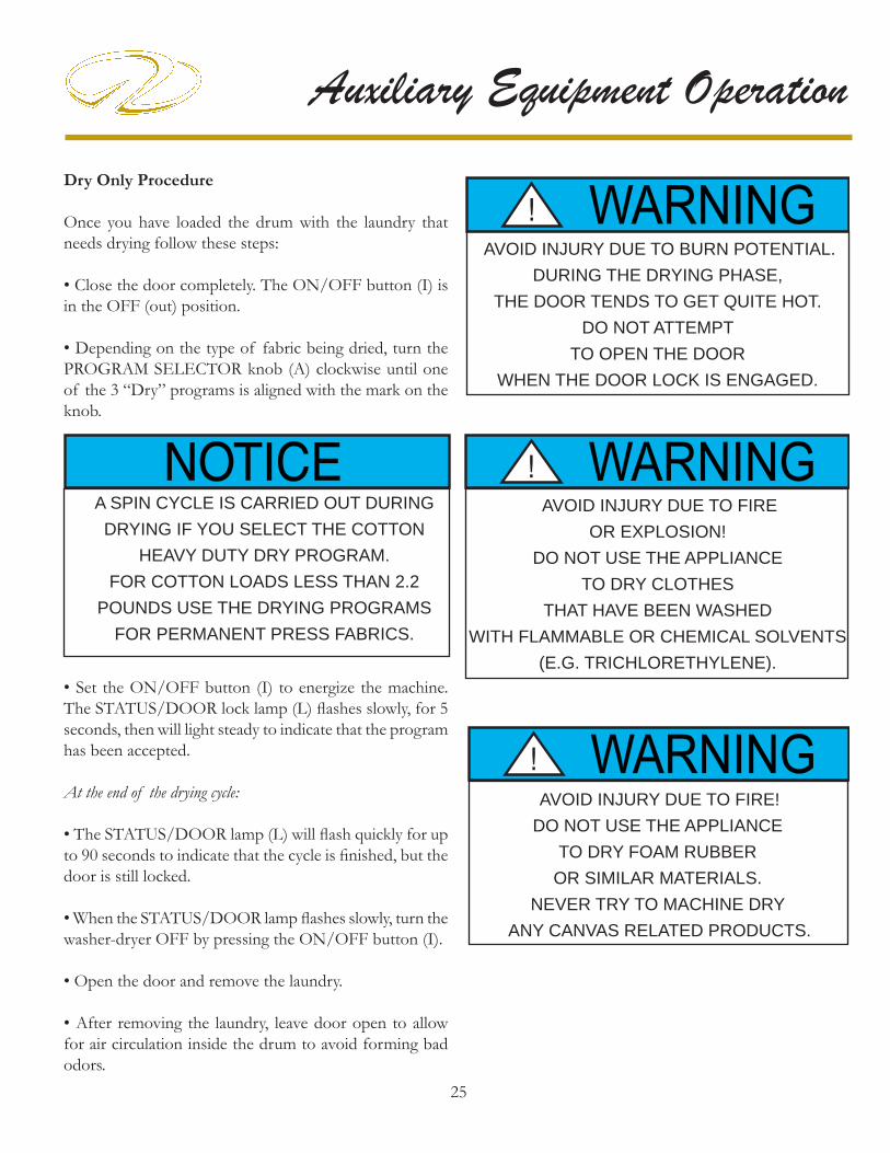
25
Auxiliary Equipment OperationDry Only Procedure
Once you have loaded the drum with the laundry that needs drying follow these steps:
• Close the door completely. The ON/OFF button (I) is in the OFF (out) position.
• Depending on the type of fabric being dried, turn the PROGRAM SELECTOR knob (A) clockwise until one of the 3 “Dry” programs is aligned with the mark on the knob.
NOTICEA SPIN CYCLE IS CARRIED OUT DURINGDRYING IF YOU SELECT THE COTTON
HEAVY DUTY DRY PROGRAM. FOR COTTON LOADS LESS THAN 2.2
POUNDS USE THE DRYING PROGRAMS FOR PERMANENT PRESS FABRICS.
• Set the ON/OFF button (I) to energize the machine. The STATUS/DOOR lock lamp (L) fl ashes slowly, for 5 seconds, then will light steady to indicate that the program has been accepted.
At the end of the drying cycle:
• The STATUS/DOOR lamp (L) will fl ash quickly for up to 90 seconds to indicate that the cycle is fi nished, but the door is still locked.
• When the STATUS/DOOR lamp fl ashes slowly, turn the washer-dryer OFF by pressing the ON/OFF button (I).
• Open the door and remove the laundry.
• After removing the laundry, leave door open to allow for air circulation inside the drum to avoid forming bad odors.
AVOID INJURY DUE TO BURN POTENTIAL. DURING THE DRYING PHASE,
THE DOOR TENDS TO GET QUITE HOT. DO NOT ATTEMPT
TO OPEN THE DOOR WHEN THE DOOR LOCK IS ENGAGED.
WARNING!
AVOID INJURY DUE TO FIRE!DO NOT USE THE APPLIANCE
TO DRY FOAM RUBBER OR SIMILAR MATERIALS.
NEVER TRY TO MACHINE DRY ANY CANVAS RELATED PRODUCTS.
WARNING!
AVOID INJURY DUE TO FIRE OR EXPLOSION!
DO NOT USE THE APPLIANCE TO DRY CLOTHES
THAT HAVE BEEN WASHEDWITH FLAMMABLE OR CHEMICAL SOLVENTS
(E.G. TRICHLORETHYLENE).
WARNING!

26
Chapter 7Wash And Dry Automatic- Procedure
If you want your load to go automatically from wash to dry do the following:
• Follow the instructions for wash only and set the DRY TIME knob (C) before pressing the ON/OFF button (I).
• The Auto Dry lamp (M) will light to indicate the dry timer has been set and at the end of the wash cycle, the appliance will run the selected tumble drying cycle.
NOTICETO OPTIMIZE THE PERFORMANCE
OF YOUR MACHINE WHEN GOING FROM WASH TO DRY AUTOMATICALLY,
ALWAYS USE FABRIC SOFTENER DURING THE WASH CYCLE.
Notes: If the laundry load to be washed and dried is too large to dry, then follow the instructions for wash only. When the wash cycle has fi nished, you will need to remove some of the items ( up to 50% ) after the wash cycle to give the remaining laundry room to tumble freely while drying. Follow the instructions for dry only. Repeat this procedure for the remainder of the load.
Notes: For your safety, the door stays engaged for the duration of the dry cycle. However, should you need to open the door during the drying cycle, two options are available:
1. You can cancel the program by advancing the program selector knob (A) to a “reset” position and waiting 5 seconds. Pilot lamp (L) will fl ash quickly, then slowly when the door lock is released. Now turn the appliance off and open the door.
2. Press the ON/OFF button (I) to turn the appliance off. Wait 1-2 minutes for the door lock to release, then open the door. When fi nished, close the door and press the ON/OFF button again. The dry will automatically resume the selected program where it left off.
NOTICETO PROTECT DELICATE FABRICS,THIS MACHINE WILL NOT ALLOW
A DRY PROGRAM TO BE SET WHEN THE SILK
OR WOOL PROGRAM IS SELECTED.
AVOID POSSIBLE FIRE!CLEAN OUT THE LINT TRAP
AFTER EACH LOAD IN THE DRYER.
WARNING!

27
Auxiliary Equipment Operation
EXTERIOR EQUIPMENT
ANTENNAE
The electronics installed on your yacht are NEMA 2000 compatible which permits system components to share information with other marine-network compatible devices. Refer to your GPS/ plotter owner’s manual for further information. Be aware of the vessel’s bridge clearance specifi cations to avoid equipment/vessel damage due to impacting a bridge structure since a great portion of the antenna/receiving equipment is mounted on the hard top. Remember that the masthead light on the hardtop can be lowered if needed.The VHF radio uses a whip style fi berglass antenna which is “trimmed” to provide the best output and reception.The TV antenna mounted on the hard top is shaped liked a saucer.The satellite weather antenna is now located under the forward deck.For further information on antennas refer to each vendor’s owners manual.
The GPS/plotter antenna is located on top of the aft hard top on early models or under the forward deck on later models. The antenna includes a built-in position fi xing receiver. The GPS plotter features a fi lter that compen-sates for the rolling motion of your boat for clearer course and speed information. The antennae are protected by individual plotter breakers.
GPS Antenna Receiver(One per GPS/Plotter)
Satellite Weather
UNDER DECK ANTENNAES SHOWN
Open Array Radar
Satellite TV
TV Antenna
TYPICAL HARD TOP ANTENNA LOCATIONS

28
Chapter 7BILGE PUMP/FLOAT SWITCH
Your Regal yacht features bilge pumps and fl oat switches in the sump (bilge) and salon (selected models). They are operated through the helm switches. There are separate switches marked forward and aft bilge pumps.In the “off ” position both switches are connected into the automatic fl oat switch. In this “auto” position if the boat takes on water, the bilge pumps will activate and pump excess water overboard. The switch will light up when activated.Periodically check the grates for debris and spray the units down with water. Make sure a steady stream of water exits the through hull fi tting indicating the entire output hose system from the bilge pump itself is debris free.Monitor your helm bilge pump switch lights periodically during your cruise. If one of the lights is on that means that bilge pump circuit is energied. Stop the vessel and fi nd the cause of the problem.
Bilge Pump
Automatic Float Switch
Grates
OutputHose
Illustration shows a typical bilge pump monitor panel which is helm mounted.

29
Auxiliary Equipment Operation
As a factory option two coats of bottom paint are ap-plied to your vessel. This product provides top-of-the-line antifouling protection. It contains the highest percentage of croupous oxide to aggressively combat even the worst tropical conditions. This product will help reduce annual hull maintenance.The hard epoxy base produces the most durable fi nish for long lasting performance. If your vessel is left in the water the paint provides effective year round service.Periodically check the bottom of the boat for growth. The vendor recommends scrubbing the bottom with a soft brush to remove anything from the antifouling surface.This scrubbing is particularly important with boats that are idle for extended periods.Note: When touching up the bottom with epoxy paint wait at least 3 days before relaunching the vessel. On older models always leave at least 1 1/2” between any metal objects including anodes and the bottom paint to help prevent electrolysis. On later models there is a shim that assures the anode is a safe distance from the paint. These models can be painted right up to the anode edge. See the illustration.
TO PROTECT AGAINST GALVANIC CORROSION
DO NOT USE BOTTOM PAINT ON ANODES.
NOTICE
Typical OceanTrac Bottom Using Shims Around Anodes
BOTTOM PAINT

30
Chapter 7
CAMERA MONITORING SYSTEM
Overview- (Includes earlier/later model cameras)
This option features day and night vision cameras. A cam-era is mounted on the hardtop or arch facing aft to assist docking operations. The second camera is in the salon. The cameras can be monitored from the helm “E” series GPS/plotter or from the salon television.The cameras are a high quality resolution color unit offering superior clear viewing in pitch black darkness. The lights radiate a blue output. The units run on 12 volt power.The cameras are part of the video display on the “E” series plotter. The cameras can be adjusted 90 degrees vertically and can be rotated manually.
Operation
You can set-up the GPS/plotter display page to view all 4 cameras at once. They are viewable on both earlier Rayma-rine and later Garmin units. Typical instructions are:
A. With the power on select OK.
B. Choose MENU.
C. Choose PAGE SET.
D. Choose CUSTOM.
E. Choose EDIT PAGE SET.
F. Select the layout (page type you want; for example fourths, thirds, etc.) with arrow pad from the selections on the display. Select OK when fi nished.
G. Choose the application (video w/camera icon) that you want to view in the window.
H. Exit- Push OK button. Cameras should be ready.
Once the display is set-up as outlined above each time you want to view the cameras from the display do the following:1. Press the red power button on the GPS/Plotter display to energize the display.
2. Select “VIDEO” 2-4 on the display to view the cameras. Three of the four videos are designated for the cameras. Video 1 is vacant for add-on equipment such as a DVD player to be viewed from the display.
To view the cameras from the salon television turn on the TV set. At the television remote control choose the “ME-DIA” button. The cameras should appear on the screen.If the set picture seems to be oblong you can adjust the picture format by pressing the “SRC” button. For viewing cameras the 4:3 format is correct. When watching regular television programming switch to the 16:9 format.
Earlier Style Camera
Later Style Camera

31
Auxiliary Equipment OperationCOMPASS
T he he lm in s t a l l ed compass is set by the manufacturer to ensure its accuracy. If in doubt it can be zeroed in by using a non-magnetic screwdriver and turning the compensator screws as recommended. A
compass can be checked while underway for variance and deviation by comparing your heading with a nautical chart or GPS. Compass error is part of the calculation. Refer to the compass manual in the owner’s information packet for compensating details.

32
Chapter 7
COOL COCKPIT AIR CONDITIONER (TYPICAL)
The cool cockpit option consists of an additional cooling unit, helm vents, and a cockpit “Elite” thermostat control.
To operate the cool cockpit:
1. Ensure the A/C seacock is opened.
2. Check the A/C sea water strainer for debris.
3. Activate the cool cockpit breaker at the AC distribution panel. This will start the A/C pump. Make sure water is seen at the thru-hull fi tting. It may take a short period to cycle.
4. Locate the Elite control behind the starboard storage cabinet door (see photo above) and follow the operating instructions as outlined in the A/C section in chapter 4.
5. By activating the aft air conditioner additional air fl ow is present at the starboard helm through the vent located there.
6. Install the cockpit canvas to maximize use of the cool cockpit.
7. Adjust the cockpit and helm vents as needed.
8. The condenser/compressor for the cool cockpit A/C unit is located in the bilge. Periodically, check the condensation tray drain for debris (see photo) and pour a measured amount of premixed in the tray to purge the A/C drain line.
9. There is a return air fi lter located on the condenser unit. Once a month clean the fi lter by rinsing with water, air dry and reinstall.
Read the A/C owner’s manual for more information.
TYPICAL A/C COCK-PIT ADJUSTABLEVENT
COOL COCKPITCONTROL(THERMOSTAT)
DRAIN
CONDENSOR UNIT

33
Auxiliary Equipment OperationDOOR-TRANSOM
Pull Up On FrameworkTo SwivelOpen OrClosed
To open the transom door (gate style) pull up on the framework until the door hinge releases and swivels to an open detented position. To close the door pull up on the framework until the door hinge releases and swivels to a closed detented position.
PREVENT SERIOUS INJURY OR DEATH
FROM FALLING OVERBOARD!
KEEP THE TRANSOM GATE
IN THE LOCKED POSITION
AT ALL TIMES.
WARNING!

34
Chapter 7
ELECTRONICS-GENERAL
Your yacht features several electronic components matched for compatibility. Manuals for each of the electronic components should be referenced for specifi c detailed operations. These manuals are part of the customer information packet.Going through each piece of electronics while at the helm with the manual will greatly decrease the learning curve time.
Note: As an integral part of upgrading our product line Regal reserves the right to change specifi cations, components, locations, and vendors at any time.

35
Auxiliary Equipment Operation
FIRE EXTINGUISHER- AUTOMATIC
OVERVIEW
The Fireboy automatic fi re extinguishing system is located in the bilge at the forward engine bulkhead. See the illus-tration. The system uses a environmentally friendly agent FE-241 which has been approved by the EPA to replace the old Halon agent. This system is formulated only for use in the engine space or bilge of your vessel. FE-241 is to be used with gasoline fuel systems only since the agent will not “stall” diesel engines. This could cause a fi re to re-fl ash.
Fireboy systems are not nor are they intended to be ex-plosion suppression devices. Boat owner’s still need to take normal precautions for checking fumes and using blowers.Read the information in chapter 4 regarding the dash in-stalled portion of the fi re extinguisher system. When the system actuation starts you may hear a loud sound simiar to that of small arms fi re, followed by a rushing air sound.The system will show actuation whenever the ignition key is ON and the indicator light is OFF. The actual actuation time when a fi re occurs is dependent on the severity of the fi re. When the automatic fi re extinguisher activates IMMEDI-ATELY SHUT DOWN ALL ENGINES, POWERED VENTILATION (BLOWER), ELECTRICAL SYSTEMS AND EXTINGUISH ALL SMOKING MATERIALS. DO NOT OPEN THE ENGINE COMPARTMENT IMMEDIATELY!Allow the agent to “soak” the compartment for a period of time and wait for hot metals and any fuels to cool before inspecting for the fi re cause. Premature opening of the engine compartment allows an in-rushing of oxygen and could result in a fl ash-back. When the engine compart-ment is opened have approved portable fi re extinguishers ready to use.
OPERATION-AUTOMATIC
OPERATION-MANUAL
If a fi re has started in the engine compartment where the Fireboy is located, DO NOT WAIT FOR AUTOMATIC ACTIVATION. Release the system manually. Close any opened hatches leading to the engine compartment, shut down all forced ventilation devices, engines, genera-tors and electrical components. Remove the safety pin from the “Fire” T-handle, and pull T-handle fi rmly and release. A loud “rushing” or air” sound will be heard. Complete discharge will take several seconds. DO NOT OPEN THE COMPARTMENT IMMEDIATELY! Keep the compartment closed for a period of time suf-fi cient to allow the agent to soak all areas of the protected space. This allows hot metals to cool.
Actuator
Pressure Gauge
Cylinder

36
Chapter 7Premature opening of the compartment could cause a re-fl ash. When opening the engine compartment for inspec-tion have hand held portable extinguishers ready.Inspect the pressure gauge and system before and after each outing. Refer to the maintenance chapter for caring for your fi re extinguisher system.The illustration opposite shows the actuator not discharged at the top and one which has been discharged at the bot-tom.
WARNING!
AVOID SERIOUS INJURY OR DEATH!
DO NOT BREATH FUMES OR VAPORS
CAUSED BY A FIRE AS THEY ARE
HAZARDOUS AND TOXIC.
WARNING!AVOID SERIOUS INJURY OR DEATH!
ACCIDENTAL DISCHARGE COULD OCCUR
DURING HANDLING, INSPECTION,
OR WORKING IN THE ENGINE
COMPARTMENT.
WEAR EYE PROTECTION
AT ALL TIMES!
Safety Pin
Pull T-HandleTo Activate
Portable fi re extinguishers are found in various cabin and cockpit lockers. On select later yachts, a label may be present on the exterior cabinet doors identifying portable fi re extinguisher locations. Know the location of portable fi re extinguishers and perform periodic inspections.
Typical Portable FireExtinguisher

37
Auxiliary Equipment OperationGENERATOR-DIESEL TYPICAL
Perform the following inspections and checks before each startup, as designated, and at regular intervals as noted in the service schedule.
1. Air Inlets- Check for clean and unclogged air inlets.
2. Air Shrouding- Ensure the enclosure is securely fas-tened and positioned correctly.
3. Battery- Check for proper electrolyte level. Make sure all battery connections are secure.
4. Coolant Level- Check the reservoir for proper levels.5. Exhaust System- Check for exhaust leaks and block-ages. Check the silencer and piping condition and check for tight exhaust component connections.Inspect the exhaust parts (exhaust manifold, catalyst, ex-haust hose, hose clamps, silencer and outlet fl apper) for cracks, leaks and corrosion.
Check hoses for cracks, softness, dents, or leaks. Replace as necessary.
Check for corroded or broken metal parts. Replace as necessary.
Check for loose, missing or corroded hose clamps. Re-place or tighten the hose clamps and hangers as needed.
Check that the exhaust outlet is unobstructed.
Visually inspect for exhaust leaks (blow-by). Check for carbon or soot residue on exhaust parts which indicate an exhaust leak. Seal leaks as needed.
As standard equipment a diesel generator is featured on your yacht. On earlier models, generators were matched to meet needs of vessels with or without the cool cockpit option. A larger generator was used for the cool cockpit option. On later models one large generator covers all optional equipment. Current generators are more powerful yet more compact in size. They run at a slower rpm for longer life.Today domestic generators are rated at 9 kw (120-240 volts, 60 hertz) and European units rated at 7 kw (240 volts, 50 hertz). Both meet current EPA, CARB and CE emission requirements.Detailed maintenance information can be found in the generator operating manual.For general generator information see chapter 4 of this man-ual.
OVERVIEW
OPERATION
Sound ShieldShown

38
Chapter 7
HARD TOP-(TYPICAL SHOWN)
The hard top features a reinforced FRP frame which pro-vides a stable mounting platform for radar and various aftermarket components. It provides shade and protection from the elements.The hard top features lighting which is energized from the cockpit aft panel or from the helm. There is an access area integrated into the ceiling for routing wiring.An aft canvas cover is available as shown above. This cover is also even more useful when the cool cockpit air option is installed.Another feature of the hartop is the electric-hydraulic sun roof. With the pressing of the helm switch the sun roof is adjustable fore and aft. The sun roof covers the full width of the cockpit.
HARD TOP-ALL WEATHER ENCLO-SURE
The optional all weather enclosure available on later pro-duction models features a sliding door and opening win-dows. The tempered glass is tinted and forms a complete weather-tight enclosure.

39
Auxiliary Equipment OperationHATCH-ENGINE
The engine hatch provides easy access for periodic bilge and equipment inspections. Use the ladder and walk-way to access the bilge from the day hatch. Be careful not to slip while climbing the ladder rungs especially if you were work-ing around the engines. Your feet may have picked up some oil deposits or lubricants from engine components.The engine compartment (bilge) lights can be accessed at the starboard stairway exterior lighting panel. Also, ad-ditional overhead lighting is available at the engine area by activating the overhead and courtesy light switches on the same panel. All light switches are individually protected by circuit breakers.Since the hatch is electric and forward facing it is easiest to access the engine compartment from the aft to check engine, IPS drive unit and generator fl uids.The engine hatch uses a single heavy duty electric-hydraulic ram to operate up and down. Should the need arise there is a top pin which can be pulled to permit the hatch to be lifted manually in case of emergencies. Note: Manually lifting the engine hatch requires additional manpower and the proper blocking to hold the hatch up. Do not try this procedure alone.
Hatch Actuator
HatchRam
RemovableHatch Pin
Typical Hatch

40
Chapter 7
The hot water heater features an eleven gallon capacity and has recirculating ability to keep water warm during cruising. This is accomplished by a set of hoses connected between the hot water tank and the circulating engine water pump. Engine coolant runs through a heat exchanger which keeps the tank water warm when the engines are running. To initially fi ll the hot water heater, ensure the boat’s fresh water tank is full. When the tank is full water will be seen at the deck vent. At the DC side of the main ship’s AC/DC panel, turn the fresh water pump to the “on” position. Make sure the water heater is full of water by opening a hot water faucet until a steady stream fl ows out. With the generator running or the shore power connected, switch on the hot water heater at the AC side of the ship’s service panel. The heating element will now begin to heat the hot water tank. Should the hot water heater reset button need to be activated on older heaters, turn off the hot water breaker at the AC side of the main control panel. Then remove the panel cover to expose the reset button. Press the red reset button. On newer models there is a round access port on the rear panel to reach and reset the breaker. Should the need arise there is a drain valve located at the rear of the heater. Always turn the hot water breaker to the “off ” position before opening the drain valve. Make sure the water is cold before attempting to open the valve. The valve runs through the shower sump pump and then overboard. Never try to adjust the thermostat or open the drain valve before turning off the AC breaker. Contact a marine professional for further information.
HEATER-HOT WATER
CAUTION!
TO AVOID POSSIBLE BODILY INJURY DUE TO HOT WATER, BE SURE TO CHECK THE
WATER TEMPERATURE BEFORE USING IT. THIS IS ESPECIALLY TRUE AFTER CRUISING
WHEN THE WATER HAS BEEN TRAVELING THROUGH THE HEAT EXCHANGER HOSES.
NOTICETO AVOID EQUIPMENT DAMAGE
DO NOT TURN ON THE HOT WATER
BREAKER WITHOUT THE WATER HEATER
BEING FULL. DAMAGE TO THE HEATER
ELEMENT WILL OCCUR.
CAUTION!TO AVOID POSSIBLE BODILY INJURY DUE TO ELECTRICAL SHOCK DO NOT TRY TO OPEN
UP THE HOT WATER TANK COMPONENTS WHILE THE AC POWER IS ACTIVATED.
TURN HOT WATER BREAKER OFF AT THE MAIN AC PANEL.
T&P VALVE
COLD WATER IN
HOT WATER OUT
HOT WATER HEATERDRAIN VALVE
RESETTABLEBREAKER
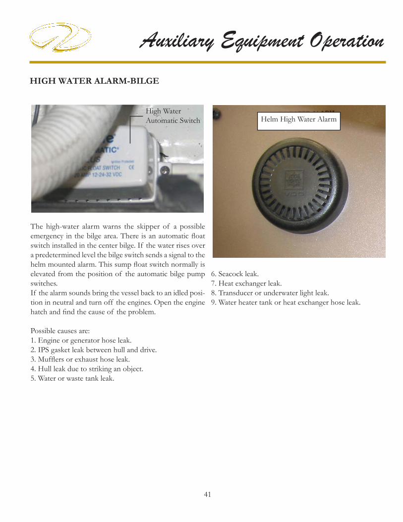
41
Auxiliary Equipment OperationHIGH WATER ALARM-BILGE
The high-water alarm warns the skipper of a possible emergency in the bilge area. There is an automatic fl oat switch installed in the center bilge. If the water rises over a predetermined level the bilge switch sends a signal to the helm mounted alarm. This sump fl oat switch normally is elevated from the position of the automatic bilge pump switches. If the alarm sounds bring the vessel back to an idled posi-tion in neutral and turn off the engines. Open the engine hatch and fi nd the cause of the problem.
Possible causes are:1. Engine or generator hose leak.2. IPS gasket leak between hull and drive.3. Muffl ers or exhaust hose leak.4. Hull leak due to striking an object.5. Water or waste tank leak.
High Water Automatic Switch Helm High Water Alarm
6. Seacock leak.7. Heat exchanger leak.8. Transducer or underwater light leak.9. Water heater tank or heat exchanger hose leak.

42
Chapter 7INSTALLING/REMOVING OPTIONAL AFT SECTIONAL FILLER CUSHION/BACKREST (42 SC)
If the aft sectional fi ller cushion option is installed follow the procedure below to remove the cushions:1. Pull the sundeck backrest forward to access the 2 knobs holding backrest bracket. Remove both knobs. See A.
2. On the forward end of the backside of the backrest cushion is another set of backrest brackets (See B). Re-move the 2 backrest bracket knob. Now pull straight up to release the backrest cushion from the 2 holders. Store the cushion.
42 SC SHOWN
BACKREST CUSHION
FILLERCUSHION
REMOVEBOTH KNOBS
3. Beneath the lower front of the fi ller cushion on both ends is another set of support brackets (See C). Remove both knobs of each set of brackets. Tilt the forward edge of the cushion up and pull it out of the way. Store it for reassembly along with the brackets and knob assemblies. Since the brackets are all the same you can mix them ac-cordingly on reassembly.
4. To reinstall reverse the process. Kneeling seems to help line up the receivers and the rods on the backrest as it improves the line of sight.
BA
C
C
LINE UP INSERTSWITH RODS
PROCESS COMPLETE
B

43
Auxiliary Equipment OperationINSTALLING/REMOVING OPTIONAL AFT SECTIONAL FILLER CUSHION/BACKREST (46 SC)
If the aft sectional fi ller cushion option is installed follow the procedure below to remove the cushions:
1. Remove the aft triangular cushion. It is normally held in place by velcro. See A.
2. Next, remove the two backrest cushions from the donut shaped inserts (B). This will expose part of the cushion support bracket.
3. On the front surface underneath the remaining cushion fi nd the latch (C). Pull on the ring and hold it while pulling up to release the cushion from its holder (D).
4. Find and pull the ring on the aft latch (E). While holding the ring out pull up on the aft end of the cushion support bracket. Release the forward end of the support bracket from the slots by pulling aft (F). This completes the pro-cess. Store all parts or if desired reverse the process and install on the opposite side of the cockpit.
A
B
C
D

44
Chapter 7
E
F
F
PROCESS COMPLETE

45
Auxiliary Equipment Operation
MARKERS-FOR SLINGS (42 SC & 46 SC)
Sling markers are located on the forward and aft deck near the rub rail. These markers provide a safe location to locate straps to lift the boat. Failure to use marked sling marker locations could cause damage to the boat structure.When lifting the vessel close all doors, hatches and port-lights. Make sure the spreader bars are adjustable enough to be wider than the sling beam area. This will allow the slings to hold the weight of the boat properly without forcing the boat structure inward. Make sure there is no pressure on the rub rail or swim platform wings. Always use a fl at wide belt-style straps as they distribute and hold the boat weight in a more supported fashion. Do not use the cable-style straps since they may cause hull or rub rail damage. See the notice below and the information in the technical drawing section.
NOTICEAS A SAFETY PRECAUTION, WHEN THE BOAT IS LIFTED,
TIE A LINE BETWEEN BOTH STRAPS TO PREVENT THE STRAPS FROM MOVING
FORWARD OR AFT.
SLING MARKER
SLING MARKER
TYPICAL AFT SECTION
TYPICAL FORWARD SECTION
NOTICETO AVOID POSSIBLE FIBERGLASS DAMAGE,
SET VESSEL FOR EXTENDED STORAGEON A FACTORY APPROVED
AND ADJUSTED STEEL CRADLE.NEVER USE BLOCKING TO SUPPORT THE
VESSEL’S HULL BOTTOM.
NOTICEBOAT OWNER-LIFT OPERATOR
Before lifting boat place a fendor or block between strap and hull just under the swim platform side wing (Both port and starboard) to relieve strap pressure on wing when lifting boat. When fender or blocking is positioned correctly strap will not put pressure on side wing when full weight is ap-plied. FAILURE TO FOLLOW THE ABOVE INSTRUC-TIONS MAY CAUSE FIBERGLASS DAMAGE WHICH IS NOT COVERED UNDER THE REGAL LIMITED WARRANTY.
REFER TO THE DRAWING IN THE TECHNICAL SECTION FOR FURTHER INFORMATION ON BLOCKING.

46
Chapter 7
3. Flip the motor control switch to the “Fill” position. The pump will start immediately and you will see the oil moving through the clear plastic tubing toward the Pump/Motor Unit. You will hear a noticeable change in sound (speed) of the pump motor when oil enters the pump.
4. Continue to operate the pump for 5 to 10 seconds after pumping action begins, then return the Pump/Motor switch to the “OFF” position and secure the oil fi ll cap.
3. Loosen the oil fi ller cap on the engine or remove the dip stick to allow air to enter the crankcase.
4. Release the fail-safe lock device on the Pump/Motor Unit valve handle and direct the arrow-shaped tip to “PORT ENGINE”.
OIL CHANGER
As optional equipment an oil change system is installed on the forward bulkhead of the engine room. It is designed to remove crankcase oil from two engines and a generator in diesel vessels. Also, the unit refi lls each crankcase oil pan with fresh oil through a system of hoses and an integrated pump.Note: This unit does not drain or refi ll the transmission housing because these engines use a separate type fl uid for the transmission.The oil change system is housed in a fi re retardant, high impact, high gloss case. The pump is solid brass with a special self-priming type impeller which pumps instantly whether in the drain or fi ll mode.Power is supplied through the vessel’s 12 volt DC system. There is a 20 amp breaker found on the DC distribution panel which is located on the forward engine bulkhead. It protects the system against overloads.
Oil Change Flow Diagram
On-Off SwitchFail-SafeDevice
Arrow-Shaped Tip
START-UP PROCEDURES
When starting the system for the fi rst time, air will be in all of the lines. To prevent pump and or system damage follow the procedure outlined below:
1. Insert the PVC wand of the Drain/Fill Hose into a container holding a small amount of fresh oil.
2. Release the fail-safe lock device on the Pump/Motor Unit valve handle and direct the arrow-shaped tip to “Starboard”.

47
Auxiliary Equipment Operation
This will lubricate the pump and insure a good starting vacuum.Run the engine to be drained until it reaches 140 degrees. This will insure that the oil can be removed easily. Shut the engine down and allow ample time for the recirculated oil to return to the oil pan.
DRAINING THE PORT ENGINE
1. Warm engine to at least 140 degrees and turn the key off.
2. Insert the PVC wand of the drain/fi ll hose into an environmentally friendly waste container since you are responsible for disposing of waste properly.
5. Flip the motor control switch to the “DRAIN” position. The pump will start immediately. You should hear a noticeable change in the sound (speed) of the pump motor when the used oil enters the pump.
6. Continue to operate the pump until there is a noticeable change in the sound (speed) of the pump motor, which is an indication air is being drawn into the crankcase oil hose and the crankcase is now empty. The oil drain rate is about one gallon per 22 seconds.
CAUTION!AVOID EQUIPMENT FAILURE!
IF OIL DOES NOT MOVE QUICKLY
THROUGH THE CLEAR TUBING
TOWARDS THE PUMP, TURN THE
SWITCH TO THE OFF POSITION,
ELEVATE THE CLEAR TUBING AS IT
NEARS THE ENTRANCE OF THE PUMP,
THEN FLIP THE SWITCH TO THE FILL
POSITION AGAIN.
7. Return the pump motor control switch to the “OFF” position when the crankcase is empty and place the fail-safe switch in the “OFF” position.
DRAINING THE STARBOARD ENGINE
1. Repeat each of the steps outlined in “Draining the Port Engine” after switching the arrow-shaped tip on the valve handle to the “STARBOARD ENGINE”.
2. Flip the motor control switch to the “DRAIN” position.
3. Once the crankcase is emptied, return the pump motor control switch to the “OFF” position and place the fail-safe switch to the “OFF” position.
DRAINING THE GENERATOR
1. Repeat each of the steps outlined in “Draining the Port Engine” after switching the arrow-shaped tip on the valve handle to the “GENERATOR ENGINE”.
2. Flip the motor control switch to the “DRAIN” position.
3. Once the crankcase is emptied, return the pump motor control switch to the “OFF” position and place the fail-safe switch in the “OFF” position.

48
Chapter 7FILLING THE ENGINES
Note: If you are using this unit for the fi rst time to fi ll the engine crankcases be sure to read and follow the information in the “START UP section.
1. Before attempting to fi ll an engine, make sure the engine has been completely drained or is in need of a measured amount of additional oil. DO NOT OVERFILL!
2. Determine the type and the amount of oil recommended by the engine manufacturer for each engine.Remember 4 quarts = 1 gallon
3. There are two commonly used methods to determine when the proper amount of oil has been delivered to the engine.
Pre-measured Method- this method requires the operator to set aside a known quantity of oil prior to fi lling. For example, if the engine requires 6 quarts of oil, the operator may want to pump from a gallon container, adding 2 additional quarts as the container empties.
Timed Method- the timed method is used when pumping from a container of unknown capacity or a reservoir. The fl ow of oil through the system varies primarily with the viscosity and temperature of the oil. Under normal conditions the system pumps 4 quarts of 40 weight oil in approximately 90 seconds. Filling time is a function of several factors, including the oil temperature and weight. Oil (40 weight) at 85 degrees F. pumps about 20% faster than the same oil at 75 degrees F.
Note: Fresh oil should be 75 degrees F. or warmer before pumping.
FILLING THE PORT ENGINE
1. Loosen the oil fi ller cap on the engine or remove the dip stick to allow air to enter the crankcase.
2. Insert the PVC wand of the Drain/Fill Hose into a container of fresh oil.
3. Release the fail-safe lock device on the Pump/Motor Unit valve handle and direct the arrow-shaped tip to “PORT ENGINE”.
4. Flip the pump motor switch on the X-Change-R to the “FILL” position. The pump will start immediately and you will observe the oil moving through the clear tubing toward the Pump/Motor Unit. You should hear a noticeable change in the sound (speed) of the pump motor when oil enters the pump.
5. Continue to operate the pump until a measured amount of oil has been pumped into the engine’s crankcase. Fresh oil is pumped at the rate of about one gallon each 90 seconds.
6. Flip the pump motor control switch to the “OFF” position when the oil pan nears its fi lled capacity and check the proper oil level with the engine’s dipstick. If fi lling is completed, place the fail-safe switch in the “OFF” position.
Note: If you have an over-fi lled engine, you may simply fl ip the motor control switch to the “DRAIN” position for a few seconds to remove the extra oil.

49
Auxiliary Equipment OperationFILLING THE STARBOARD ENGINE
1. Repeat each of the steps outlined in “Filling the Port Engine” after switching the arrow-shaped tip on the valve handle to the “STARBOARD ENGINE”.
2. When the oil pan nears its fi lled capacity, fl ip the pump motor control switch to the “OFF” position and check the proper oil level with the engine’s dipstick. If fi lling is completed, place the fail-safe switch in the “OFF” position.
FILLING THE GENERATOR
1. Repeat each of the steps outlined in “Filling the Port Engine” after switching the arrow-shaped tip on the valve handle to the “GENERATOR” engine.
2. When the oil pan nears its fi lled capacity, fl ip the pump motor control switch to the “OFF” position and check the proper oil level with the engine’s dipstick. If fi lling is completed, place the fail-safe switch in the “OFF” position.

50
Chapter 7
Fuse
FUSE
Fuse
FUSE
OVERBOARD DISCHARGE PUMP (MAC-ERATOR) TYPICAL
The overboard discharge pump (macerator)) can be used to pump out the holding tank in international waters.When the monitor panel key is energized to the full start position, the macerator engages to pump the tank waste overboard. Again, make sure it is legal to pump the waste overboard before you start the operation. Also, open the waste seacock lo-cated in the sump. The pump can be disconnected from the 2 union fi ttings that hold it for maintenance purposes.The pump is rated for 40 minutes continuous operation.Do not fl ush paper or feminine hygiene products into the waste system. Keep toilet tissue usage to a minimum. Do not use bleach or toilet cleaners in the waste system. Use only maine approved products. Rinse and fl ush the hold-ing tank after each pump out. This will dilute any residual waste, and help prevent blockage and reduce odors.
FRESH WATER & WASTE MONITOR WITH OVERBOARD DISCHARGE
Key Switch
TYPICAL OVERBOARD DISCHARGE PUMP
The impeller grinds up the waste as it passes through the macerator. On the macerator shown above the system is protected by a 10 amp breaker located at the salon main DC distribution panel.
IN-LINE WASTE VENT FILTER
Normally found in the bilge near the through hull fi tting is a long cartridge style fi lter installed in-line at the waste tank vent hose. This fi lter removes waste odor from the system while still permiting methane fumes to escape via the hull side.The waste fi lter is not seviceable. The manufacturer rec-ommends that it be replaced each year.
Waste SystemIn-LineFilter
46SC Shown

51
Auxiliary Equipment Operation
PRESSURE PUMP-FRESH WATER Your vessel features a variable speed fresh water pressure pump. The variable speed allows for additional water fl ow at peak times such as using the forward and aft showers at one time. It is important not to operate the pump un-less there is water in the fresh water tank. The pump is controlled by a breaker on the main DC control panel. Energizing the switch allows the pump to build the water pressure in the distribution lines to 35 psi’s. When the pump reaches a level of 35 psi the pump should automatically shut off. If the system drops below a certain pressure then the variable speed pump will restart. If the pump cycles on and off with no water being used, a leak in the water system is likely.Periodically remove the water inlet fi lter and clean it. Additional fi lters can be ordered through your Regal yacht dealer or marine outlets. Be sure to turn the fresh water pump at the main salon DC panel off before performing any type of maintenance.
Filter
Fresh WaterPump
TYPICAL FRESH WATER PUMP
In Out

52
Chapter 7
SATELLITE RADIO
This option is currently available on all Regal models. Sirius satellite radio features over 120 channels of music entertainment completely commercial-free along with sports and news channels. Sirius emphasizes the music and entertainment you want. Channels use the most updated digital fi ltering available for the clearest sound. Sirius uses three satellites fl ying over the United States for coast to coast coverage with high elevation angles. The result is a clearer line of sight and less signal blocking.The system consists of the stereo receiver (sometimes called the head unit), radio tuner and antenna. With these components and an active account initialized by the customer on delivery your Sirius system should be ready to operate.
Following are the activation steps to be taken:
A. Unit must be completely installed and the antenna must have a clear view of the sky.
B. Turn on the radio and go to satellite mode.
C. Confi rm reception by tuning to SIRIUS WEATHER & EMERGENCY//CHANNEL 184. If you are not receiving Channel 184, please refer to the radio manufacturer owner’s manual.
D. Call SIRIUS sales support 1-888-465-8516 or customer care 1-888-539-7474.
E. Please have your name, address, phone number and the SIRIUS ID#ESN available for the agent.

53
Auxiliary Equipment OperationSHOWER-TRANSOM TYPICAL
The transom shower is located at the aft stairway portion of the cockpit. The shower head features a fl exible extended hose with hot and cold water. Like residential plumbing, the red knob denotes hot water and the blue knob cold water. When using this feature balance the hot and cold knobs to achieve a desired operating temperature. Turn the knobs to the “off ” position when not using the unit.
Hot WaterFaucet
Cold WaterFaucet
Shower Head

54
Chapter 7SIRIUS MARINE WEATHER-TYPICAL
This option provides peace of mind and safety by allowing the captain to access the latest weather information through satellite. The data can be viewed through the “E” series GPS/Plotter (option) at the helm or the salon television.The service provides comprehensive weather data and state-of-the-art forecasting including buoy reports, WSI NOWRad® (nationwide high-resolution weather radar imagery) to anticipate coming trouble and high-resolution sea surface temperatures that can help fi sherman.Subscribers can use the SIRIUS satellite footprint which blankets 48 contiguous states, most of Canada and Mexico; and waters extending hundreds of miles into the Atlantic and Pacifi c oceans, the Gulf of Mexico and Caribbean. SIRIUS MARINE WEATHER ACTIVATION
1. Power up the receiver by activating the power button on the “E” series GPS/Plotter.
2. Dial 1-800-869-5480 to activate the service. The cus-tomer normally carries out this operation. Regal supplies a 6 month subscription for the customer.
3. Be prepared with your billing information, subscription preferences and the SIRIUS ID# for your receiver.
4. The SIRIUS ID# of your receiver will be viewable via the “E” series GPS/Plotter.
OVERVIEW
The following information is for United States weather only. A Navtex receiver must be used for worldwide weather.The weather application superimposes historical, live and forecasted weather graphics and their associated weather data on the “E” series GPS/Plotter. All this information allows the skipper to determine the actual conditions in his vicinity or at another location. Weather forecasts and warnings, detailing current and preferred conditions are updated often using the WSI NOWRad® system.For types of warnings, watches and advisories, please refer to the NOAA website at www.nws.noaa.gov.
OPERATION
To operate SIRIUS marine weather:
1. The Raymarine SR100 (earlier) or Garmin (later) receiver must be up and running. Also, it will not work in a covered boat house or dwelling.
2. The “E” series GPS/Plotter must be energized.
3. For your vessel to be displayed and for weather reports to be available at your position, you will need a fi x for your boat’s position and be within US coastal waters.
3. You must customize a page to include a weather applica-tion. The weather application normally is not part of the pre-confi gured page sets. See the following page.
4. Specify the weather elements you want to display.
5. When you open the weather application, a map is dis-played. If you have fi xed a position for your vessel, the map will be centered on your boat.
6. Use the cursor to move around the map and view dif-ferent locations. Use the range button to zoom in and out. For re-centering the map on your boat, use the FIND SHIP soft key.

55
Auxiliary Equipment Operation
Sirius Marine Weather Map(Typical)
Typical Weather Application Set-Up
To customize a page on the “E” series GPS/Plotter for weather do the following:
1. Press and hold the “PAGE” key until the “SELECT PAGE SET” box appears.
2. Using either the rotary knob or the directional pad, select the page set to which you wish to add weather.
3. Press the soft key labeled “EDIT PAGE SET”, then press the soft key that corresponds with the page you wish to edit.
4. At this point, you will be able to change the page layout using the directional pad and re-confi gure all windows in the page or you can leave the layout the same by pressing OK.
5. Press the “ACTIVE” key repeatedly until a red box ap-pears around the application for the selected window (in this case, weather).
6. When your page is set up with the desired set of ap-plicatiions, press “OK”.
Note: Once you actually start to manipulate the pages, on screen instructions will guide you through the process.
Re-confi guring For Weather Application
Editing A Page Set

56
Chapter 7
SPOTLIGHT-TYPICAL
The “5” spotlight/fl oodlight uses a high-powered, dual focus sealed beam bulb. With an output of 72,000 candlepower, the unit can illuminate objects up to 1/4 mile away. Notwithstanding, the 30,000 candle power spotlight is perfect for docking or mooring. The unit rotates up to 350 degrees and includes a vertical arc
of 70 degrees and an easy to use “joystick” style remote control. The spotlight uses a 12 volt operating system and is constructed of stainless steel or chrome brass for years of carefree service.
The spotlight control panel uses a 2 way switch to control the type of light output. To control the direction a 4 posi-tion joystick style switch is used.The 2 way switch in the center position is “off ”. In the “up” position the light output is a spotlight. In the “down” position the light output is a fl oodlight.To move the light upward press and hold the joystick “up”. To move the light downward press and hold the joystick “down”. To move the light counterclockwise press and hold the joystick to port until the desired directional movement is achieved. To move the light clockwise press and hold the joystick to starboard until the desired directional movement is achieved.If storing the vessel outside in colder climates turn the spotlight so the lens faces the stern of the boat to help prevent a broken lens due to unidentifi ed fl ying debris. Of course another option would be to cover the lens face.
Joystick

57
Auxiliary Equipment Operation
SUN LOUNGER-EURO DESIGN
The aft cockpit Euro sun lounger is extra wide to comfor-ably support several persons. The headrest can be posi-tioned for aft or forward facing positions.
SUNPADS
The forward deck features dual sunpads. Each sunpad cushion is lightweight making it easier to transport to the deck and easier to store. The backrests can be individually adjusted to several postions.The dual foredeck sunpad must be used only when the boat is stopped to avoid anyone falling overboard. Make sure the cushions are snapped down securely. It is a good idea to store the sunpad cushions when not in use to prevent them being blown overboard should the yacht encounter inclement cruising weather.
AVOID SERIOUS INJURY OR DEATH
DUE TO FALLING OVERBOARD!
DO NOT USE THE DECK
SUNPAD WHILE BOAT IS MOVING.
WARNING!

58
Chapter 7SWIM (BOARDING) LADDER
When using the swim (boarding) ladder open the hatch and slide the ladder out to the end of the travel. Then fl ip the ladder over and let it down gently. Make sure you keep your hands and fi ngers clear of any moving ladder parts especially the hinged top.Use the safety handrails to ease water entry and exit. When not using the swim ladder be sure to keep the ladder cover over the ladder to prevent tripping and falling accidents.
TO AVOID BODILY INJURY
TURN THE ENGINES AND GENERATOR OFF
AND REMOVE THE IGNITION KEYS
WHILE PEOPLE ARE SWIMMING
NEAR THE VESSEL AND/OR USING THE
SWIM PLATFORM OR LADDER.
WARNING!Keep Body Parts
Away FromRotating Components
TYPICAL YACHT LADDER
Handrails
Insist that only one person use the ladder at a time. When fi nished with the ladder fl ip up the lower section of the ladder and slide the ladder assembly in as far as possible. Lower the fi berglass ladder cover to secure it.Periodically check the ladder hardware for tightness and corrosion. Replace fasteners and lubricate hinges as
needed. Read and understand all warning and informa-tion labels found on the swim platform and lad-der cover. Never exceed the maximum poundage recommended for the swim platform as noted on the label.
Labels

59
Auxiliary Equipment OperationSWIM PLATFORM
The swim platform is used with the boarding ladder to enter and exit the water. Never dive from the swim plat-form or swim under it. The swim platform is not intended to be used for storing heavy objects. Keep the platform surface free of objects to prevent bodily injury due to fall-ing. Periodically inspect all swim platform fasteners and stanchions under the platform for tightness and corrosion. Replace parts as needed. Do not exceed the swim platform recommended pound-age capacity.
CLEAT FOR TEMPORARY TYING ONLY
CLEAT FOR TEMPORARY TYING ONLY
NEVER SWIM UNDER PLATFORM
TYPICAL YACHT SWIM PLATFORM (42SC SHOWN)
Use the swim platform cleats for temporary tying only such as stopping at an on-the-water restaurant or fuel dock. Use the other deck cleats for permanent moorings. When securing lines leave enough slack for local tidal changes. Never use the swim platform cleats for towing! Never attempt to lift the boat using the swim platform cleats or any other cleats on the vessel! See the section on sling markers. Never swim around or under the swim platform while the engines are running due to the effects of carbon monoxide poisoning. Read and understand all CO labels in the safety on board chapter.
MOORING CLEAT
MOORING CLEAT

60
Chapter 7
TO AVOID BODILY INJURY
TURN THE ENGINES AND GENERATOR OFF
AND REMOVE THE IGNITION KEYS
WHILE PEOPLE ARE SWIMMING
NEAR THE VESSEL, USING THE SWIM
PLATFORM OR LADDER.
WARNING!
WARNING!AVOID SERIOUS INJURY OR DEATH!
NEVER OPERATE THE VESSEL
WITH PEOPLE ON TOP OR HOLDING ON TO
THE SWIM PLATFORM
STRUCTURE OR HARDWARE.

61
Auxiliary Equipment Operation
UNDERWATER LIGHTING
OVERVIEW
The underwater light option provides high output, long life and low heat emission. The lights are made from a high impact resistant polycarbonate housing. The lights are installed under the transom for maximum effi ciency. Their beam is blue for increased underwater penetration.
OPERATION
The underwater lights are energized through the acces-sory switch located at the starboard helm switch panel. The lights are protected by a 5 amp in-line fuse normally located at the transom area.
Earlier Underwater Light Shown
Later Underwater Light Shown

1
Cosmetic Care & Maintenance
COSMETIC CARE
This chapter covers the general care of your Regal yacht. Be sure to read and understand all vendor supplied information on cosmetic care. Many cosmetic care topics are described and expanded in the following pages. For selected items there may not be specifi c
vendor information available in the owner’s information packet. Therefore, we have provided customer cleaning information as needed on each of these topics.Where cleaning methods are suggested try them on a small area before applying to the entire surface. Never use toxic or caustic chemicals on your yacht. Read and understand each cleaning agent before using it. The labels will alert you to limitations and safety information for each cleaner.Never mix cleaning agents since this may produce an unsafe chemical reaction which could be toxic, produce fi re or explosion and/or effects that may be harmful to the human body.Provide fresh air while using cleaning agents to reduce any effects of chemical inhalation by opening hatches, portlights and the main companionway door. It is recommended to vacate the area until any chemical odors are diminished.
Most of all, use common sense!
2
Chapter 8TABLE OF CONTENTS
Bilge-Engine Compartment 3Bottom Paint 3Cabinets 4Sunbrella Canvas Cleaning Instructions 5Clear Vinyl, Zipper & Snap Care 5Carpet 6Corian 9Electric BBQ 10Fabrics-Interior 10Fiberglass & Gelcoat 11Flooring 13Gauges/Switch Panels 14Granite 15Hull/Deck 17Microwave Oven 17Plastics 18Range 18Spotlight 19Stainless Steel 19Stains 20Upholstery 21Window Film 22
COSMETIC CARE MAINTENANCE
Air Conditioner 24Batteries 27Battery Parallel Switch 31Battery Switch Panel 31Bilge Pump/Float Switch 32Camera Monitoring System 33Carbon Monoxide Detector 34Compass 34Door-Cabin Entry 35Electronics-General 35Electronics-VHF Marine Radio 36Fire Extinguishing System 37Fuel System 38 Generator-Diesel 39Ground Fault Outlet 42Heater-Hot Water 43High Water Alarm 44Horn 45Oil Change System 46Plumbing Connections 47Pump-Fresh Water 48Pump-Overboard Discharge 49Sirius Marine Weather 50Shower Sump Pump 50Stereo/DVD/TV 51Television Flat Screen Monitor 52Trim Tabs 53Underwater Hardware (Seacocks) 54 Vacuum Style Toilet 55Vacuum Cleaner 56Volvo Engine/IPS Drive 57Washer/Dryer 65Windlass 67

3
Cosmetic Care & MaintenanceBILGE/ENGINE COMPARTMENT
Always keep the bilge pumped out and free of accumulated debris. If oil accumulates on the engine compartment fl oor becomes it is usually related to engine oil lines, a loose component such as an oil fi lter, oil pan drain bolt or a leaky gasket/O-ring. Always fi nd the cause of smaller problems before they become larger more expensive ones.The engine compartment, bilge or sometimes called the sump features a light colored gel fi nish that will be benefi cial in fi nding leak sources.A periodic bilge cleaning with a brush and bilge cleaner(purchase at a marina or supplier) will be helpful in maintaining an orderly and safe bilge since accumulated dirt and fl uids could cause someone to fall. Do not pump bilge contaminated oil overboard but deploy it to a waste receptacle for recycling. Check the fuel system including all hoses, tanks and connectors for possible leaks and deterioration. A stained area normally could suggest a hose or connection leak. Inspect all wiring including connectors and hangers for tightness. Clean fuel fi lters as suggested by the engine manufacturer.Check all engine and water/waste hoses for tightness and deterioration. Tighten all hose clamps as needed.Check all battery hardware and terminal connections. Fill the battery cells with distilled water (wet-cell type only) to the battery manufacturer’s suggested level.Check the transom area for loose hardware. With IPS systems refer to the vendor owner’s manual for any engine room maintenance on the stern drive system.Do not use any fl ammable products in the bilge. Use environmentally approved procedures to dispose of oily or soiled cloths.
BOTTOM PAINT
Bottom paint in fresh water normally accumulates a bit of algae and slime over a period of time even more so if the vessel is not used. Most of this can be wiped off with a turkish towel or the back side of a piece of rug while the boat is in the water. Stay away from using a stiff bristle brush, wire brushes or abrasive materials which may harm the bottom paint barrier.If used in saltwater the bottom may have accumulated some barnacle growth. Sometimes a diver can be hired in lieu of hoisting the vessel to clean the growth.Periodically, the best way to inspect the bottom is to have the boat lifted out. Make sure the straps are evenly lined up with the sling markers on the deck. Look for scrapes in the gelcoat along with any loose or damaged underwater hardware. Also, this is an excellent time to check for damaged propellers and underwater hardware. The hull bottom and paint should be inspected annually and touched up as needed by your Regal yacht dealer.Make sure to leave the required spacing (at least 1”) when touching up to protect hull components ie; trim tabs, drive parts, anodes from electrolysis potential. Never paint any of the above mentioned parts with bottom paint.
WIRE BRUSHES, SCOURING PADS, OR OTHER ABRASIVE TYPE MATERIALS
AND SOLUTIONS SHOULD NEVER BE USED ON THE HULL OR DECK
OF YOUR BOAT. THEY CREATE SMALL SCRATCH
MARKS THAT WILL COLLECT MARINE GROWTH AND OTHER FOREIGN
MATERIALS.
NOTICE

4
Chapter 8CABINETS
The handcrafted interior cherry cabinets feature a sprayed clear coat fi nish. This clear coat produces a hard fi nish which is baked on and is very resilient. Use a warm solution of water and mild detergent to keep the cabinet surfaces looking new. Wipe the surface with the solution using a soft damp cloth, and dry with a soft clean towel. This procedure should eliminate most stains and oily fi nger marks. Stay away from heavy scrubbers and compounds which may harm the surface. Avoid polishes containing silicones.
Use the specifi cations below as a guide for any cabinet repairs or interior refurbishing needs.
APPLICATION ADHESIVE
WOOD TOWOOD
WOODGLUE
WOOD TOFORMICA
CLEARSILICONE
FORMICA TOFORMICA
CLEARSILICONE
SINK INSTALL CLEARSILICONE
CORIAN TRIM SIKA FLEX291
MIRROR TOFORMICA
MIRRORMASTIC
GRANITE SIKA FLEX TO WOOD 291

5
Cosmetic Care & MaintenanceCANVAS CLEANING INSTRUCTIONS
Sunbrella type canvas should be cleaned regularly before substances such as dirt, roof particles, etc., are allowed to accumulate on and become embedded in the fabric. The fabric can be cleaned without being removed from the boat. Simply brush off any loose dirt, hose down, and clean with a mild solution of natural soap in lukewarm water. Rinse thoroughly to remove soap. DO NOT USE DETERGENTS! Allow to air dry.For heavily soiled fabric, remove the top from the frame. Soak the fabric in a solution that has been mixed to the following proportions: 1/2 cup of Clorox bleach and 1/4 cup of Ivory or Lux soap (liquid or soap) per each gallon of lukewarm water. Allow the fabric to soak until the bleach has killed the mildew and the stains can be brushed out with a common kitchen scrub brush. Rinse the fabric thoroughly in cold water to remove all the soap. This may require several rinsings. Incomplete rinsing can cause deterioration of sewing threads and prohibit the fabric from being properly retreated. Allow the fabric to dry completely.
DO NOT STEAM PRESS OR DRY IN AN ELEC-TRIC OR GAS DRYER!
Excessive heat can damage and shrink the fabric since it is heat sensitive.This method of cleaning may remove part of the water and stain repellents that was applied to the fabric during its manufacture. It is recommended to retreat with such water repellency products as Apseal and Uniseal. We do not recommend any wax based treatments such as Thomp-son’s Water Seal or any of the silicone products such as SC-15 or Aqua-Tite. Wax based products prevent the fabric from breathing, and encourage mildew growth while the silicone products interact with the original fl uorocarbon fi nish and seem to cause a rapid loss of water repellency. Scotchguard has not been found to be very effective for restoring water repellents to Sunbrella. It seems to work well in the short run, but not long term.
CLEAR VINYL, ZIPPER & SNAP CARE
Never store canvas wet or in an unventilated, moist area. Always roll the canvas instead of folding. This is of par-ticular importance on side curtains or any other part with the clear vinyl “glass”. Roll the top carefully around the bows and cover with the storage boot provided. The clear vinyl “glass” used in side curtains, aft curtains, visors, and camper enclosures is very susceptible to heat and cold. Keep vinyl curtains from touching metal tubing to minimize burning the vinyl.If the boat is stored with top, side curtains and aft curtain in place, heat build up inside the boat may discolor the vinyl.To clean the clear “vinyl” glass, use a solution of Ivory or Lux soap, liquid or fl akes, and lukewarm water. Allow to air dry. Never use any type of abrasive cleaner as it will scratch the “vinyl” glass. There are many cleaners and scratch removers on the market specifi cally for clear vinyl. Handle the clear curtains carefully. They are soft and prone to scratching.Canvas parts are designed with zippers. When zippers are new they can be a little diffi cult to use. Zip carefully without forcing the zipper or the material. They will loosen with use. A zipper lubricant may be used to help new zippers as well as maintaining used ones. The most vulnerable part of the zipper is the starts. Use care when starting the zipper.Canvas snap fasteners should be unsnapped as close to the button as possible. Never remove canvas by pulling roughly on the edge of the material. This can damage the canvas as well as the fasteners. Use petroleum jelly on snaps to keep them from developing corrosion especially in harsh environments.

6
Chapter 8
The interior cabin carpet is produced from 100% BCF nylon. The nylon is treated tropically with an anti-soil chemical that will assist in keeping your carpet looking beautiful longer.
General Care and Maintenance
Your carpet is a high luster nylon that can look great for years to come provided you follow some basic care and maintenance. Nylon is the highest performing synthetic fi ber in the market and has dense pile that will give a long wear cycle and high performance.The following will help maintain your carpet:
Regular Vacuuming
This is the most important single factor in keeping carpet beautiful is to vacuum it on a regular basis. Sand and dirt particles will abrade the carpet fi bers in a faster manner. This abrasion will cause non-repairable damage to the fi ber that will reduce the carpet’s life expectancy. Use a vacuum with a beater bar verses a vacuum alone as it will lift the fi ber and help open the carpet to allow the vacuum to remove grit.
Professsional Cleaning
Interior carpet is the same as high-end residential carpet and the carpet should be treated accordingly. Periodic pro-fessional carpet cleaning using either the hot water extrac-tion or dry cleaning powder method will help manintain the beauty of your carpet. This will remove the ground in soil.
CARPET-INTERIOR Spills
At some point in the life of the carpet, there is always the potential for a spill. Remove the spill immediately. The quicker the spill is removed, the easier it is to clean up. The longer a spill stays on the carpet, the more likely it is to stain the fi bers, regardless of the cleaning treatment used. When a spill occurs, always blot the area being cleaned. Do not rub or scrub. Follow the cleaning instructions.
Cabin Door/Cockpit Entrance Mats
Entrance mats on a boat are very important to help re-duce the dirt and sand that is brought on to the carpet. Also, entrance mats reduce the amount of moisture being tracked on to the carpet, which will cause matting of the fi bers. Mats can be ordered from your Regal dealer. These mats fi t the nautical decor and provide the best surface to catch dirt and sand particles. Also, entrance mats can be ob-tained from local sources. Look for mats with a non-skid backing.

7
Cosmetic Care & Maintenance
To store cockpit carpet, roll it tightly. This will keep the carpet from developing wrinkles which result from folding the carpet.
CARPET-COCKPIT
Regal cockpit carpets feature an aqua tread backing which permits the carpet to weep moisture and still retain stead-fast non-slip characteristics. Also, this backing permits the cockpit carpet to lay fl at on the fi berglass deck surface without buckling.Also, your cockpit carpet is produced with 100% ultravio-let resistant fi bers. The carpet boasts a special blend of resilient fi bers to withstand traffi c and retain its beauty.Cockpit carpet is designed to take a lot of abuse from the sun and sea but it periodically needs to be cleaned which is a different procedure from household types.
To clean cockpit carpet follow these steps:
1. Scrub the soiled areas with a stiff nylon or soft bristle brush to loosen the dirt and grime.
2. Vacuum the carpet thoroughly using a wet-dry type of cleaner.
3. Pour one cup white vinegar into a 1-quart spray bottle; fi ll with water.
4. Spray the soiled areas with the vinegar solution until saturated; let stand 15 minutes.
5. Brush the soiled areas once more; the dirt and grime will be released from the carpet fi bers.
6. Rinse the carpet, with a garden hose at low pressure.
7. Remove any remaining water with a wet-dry vacuum. Allow the carpet to dry completely.
8. Fluff up the clean, dry carpet with the brush or a car-pet rake. If applicable, apply vaseline to the snaps.
Stain Removal
Olefi n fi ber used in the cockpit carpet is very resistant to stain. However, when a stain does occur, follow the stain removal chart on the following page. Remember, remove a stain as soon as possible, as this enhances the ability to remove it.Most stains should easily be removed from olefi n fi bers. If the stain persists, the cleaning procedure should be repeated to ensure stain removal. Again, the sooner the stain removal process is started, the easier the stain will be to remove. Under no circumstances should any solvents normally associated with the dry cleaning of apparel (perchloreth-ylene, carbon tetrachloride, etc,) be utilized, as perma-nent damage to the fi ber will result.

8
Chapter 8
Miscellaneous Stains Removal ProcessCoffee, Tea, Coke, Fruit Juice, Ice Cream, Motor Oil, Egg, Grease, Catsup, Chocolate, Milk, Rust, Latex Paint, Water Col-ors, Berry Stains, Blood, Salad Dressing, Furni-ture Polish, Clay, Wine, Dye, Mayonnaise, Fish Formula or Urine
Apply warm water and household detergent in minimal amounts to the stained area. Sponge or scrape the stain until it is removed. Then wash thoroughly with clean water.
Persistant Stains Removal ProcessChewing Gum, Crayon, Ink, Wax, Lipstick, Tar, Polish, Oil Paint
Apply warm water and household detergent. Work mixture well into the stained area, and then fl ush with warm water.
Cockpit Carpet Stain Removal Chart

9
Cosmetic Care & MaintenanceCORIAN®
Regal has chosen Corian® countertop material because of its elegance and durability. Periodic maintenance will ensure its beauty. Corian withstands heat much better than ordinary countertop materials but you must still use a hot pad or trivet when taking materials directly out of the oven or stove top to protect from damaging the surface. Avoid cutting directly on the surface.Another feature of a Corian countertop is that it is non-porous. Therefore, dirt and germs do not penetrate it. Corian will not support the growth of germs and mildew. To disinfect or clean see the table. You can use a green Scotch-brite pad along with the table solutions to remove stubborn stains.Darker colors tend to require more frequent cleaning to maintain a uniform fi nish. Also, darker colors tend to show fi ne scratches more easily and require more attention than lighter colors. Corian is a matte or satin fi nish. To remove scratches and nicks, sand the surface with 180-220 grit sandpaper until the nick is gone. To restore the fi nish use an abrasive cleanser and a green Scotch-Brite pad. Wrap the sandpaper around a block of wood. The block will sand the areas fl at instead of creating hills and valleys.
PROBLEM SOLUTIONDirt and Residue Use soapy water, am-
monia based cleaner (not window cleaner), rinse and wipe completely dry. Commercially available solid surface cleaners such as Clean Encoun-ters® will work well too.
Preventing Hard Water Marks
Rinse & wipe completely dry after cleaning; clean up spills before they dry.
Removing Hard Water Marks
Use a cleaner formulated for removing hard water marks such as CLR or Lime-A-Way
Diffi cult Residue Spray residue with Deep Cleaner for DuPont Corian from Stone Care International. Follow in-structions on the bottle. Wash area with soapy water, rinse and wipe completely dry.
Disinfecting Occasionally, wipe surface with diluted household bleach (1 part water/1 part bleach). Rinse top thoroughly with water and wipe completely dry.
10
Chapter 8FABRICS-INTERIOR
Clean fl at good interior fabrics with dry cleaning fl uid style cleaners approved for use with soft fabrics. Allow adequate ventilation and follow the label instructions care-fully. Use protective eye wear and gloves. Do not inhale the chemicals. Use a soft cleanser with feldspar to clean stubborn marks or stains on wallpaper. Normal interior vinyl such as the headliner need a mild soap and water solution. Rinse immediately with clean water and wipe dry. Always test a small area with a cleaner before applying it to a larger area.
ELECTRIC BBQ
STAINLESS STEEL SURFACES
The best way to clean metal surfaces on your BBQ is to wipe them down wih a damp cloth and then thoroughly dry. Stubborn spots caused by spillage and discoloration from heat may be removed by lemon juice, vinegar, or chrome polish. Keep these cleaning products away from porcelain enamel surfaces. Never use coarse cleaners, steel wool scouring pads or metal brushes to clean stainless steel. These methods will allow deep scratches to develop on the stainless steel that cannot be removed.
PORCELAIN ENAMEL
Porcelain enamel is glass fused on steel at very high tem-peratures. It is not overly delicate but must be treated like glass. Sharp blows, radical changes in temperatures, etc; will cause the enamel to crack or chip. Some foods contain acids which will dull the fi nish of the enamel.

11
Cosmetic Care & MaintenanceFIBERGLASS & GELCOAT
Routine maintenance is the only practical way to keep the surface of your boat looking shiny and new. Most objects left outdoors will gradually deteriorate from exposure to the sun, water, dust and pollution. Such outdoor expo-sure can cause your boat’s gelcoated surface to change or fade. Darker colors tend to fade more rapidly than lighter colors because they absorb more of the sun’s rays (ultraviolet and infrared). Basic maintenance includes monthly washing of the boat’s surface to remove normal accumulation of soil and stain. Use a mild detergent such as dishwasher powder or liquid. Do not use automatic dishwasher detergent. Avoid any kind of alkaline cleaners such as tri-sodium phosphate (TSP), abrasives, bleaches and ammonia. For best results use cleaners that are recommended for fi berglass.
When the washing and waxing as recommended does not restore the shine it may be necessary to use a fi ne rubbing compound. Do not apply rubbing compound in direct sunlight. A power buffer at lower speeds does an excel-lent job to remove impurities from the gel coat that cause dulling. Use light pressure and keep the buffer moving. Re-wax after compounding to buff the surface. “Hairline cracks” or “spider webbing” could develop in the gelcoat surface of a hull or deck. This can be caused by impact or other factors. Small air pockets or gouges may also occur through normal wear. These do not affect the strength of the hull or deck and can be repaired by yourself, a marine professional or a Regal dealer.The affected area should be chipped or sanded away and a thin layer of color matched gelcoat applied. This layer is then sanded smooth and buffed to its original luster. Most minor scratches, nicks, and dents can be removed by compounding the surface. Marine type compounds can be found at most auto body supply stores. Specify a number 25 which is a coarser compound up to a number 55 being less coarse. Various glazes and polishes are available as needed. Ask your marine professional or Regal dealer for more information. Fiberglass hulls are strong but they can be damaged. A fi berglass hull has vir-tually no internal stresses. Thus when a part is broken or punctured, the rest of the hull retains its original shape. A severe blow will either be absorbed or result in a defi nite localized break. A break of this nature should be checked and repaired by a marine professional or a Regal dealer.
MINOR REPAIRS
You will need the following materials for minor repairs:
• Gelcoat• Clear Liquid Catalyst• Putty Knife• Razor Blade• Fine Sandpaper (400,600,1000)• Wax Paper (to cover repair area)
It is recommended that you wax the gelcoat surface twice yearly to prevent loss of gloss and to protect the fi nish. Use only waxes for fi berglass and follow the label instructions. Apply a 3’ x 3’ section at a time using clean applicator cloths or a buffi ng bonnet. When a haze devel-ops, use a power buffer at low speeds (1200-2000 rpm) to remove the haze. Keep the buffer moving to avoid heat build-up. Never wax gelcoat in direct sun.
AVOID BODILY INJURY!WAXED GELCOAT SURFACES CAN BE VERY SLIPPERY. DO NOT WAX NORMALLY USED
AREAS OF THE DECK, LINER, OR GUN-WHALES. DO NOT WAX ANY TEXTURED OR
NON-SKID SURFACES SUCH AS FLOORS, WALKWAYS, STEPS, LADDERS
OR SWIM PLATFORMS. ALWAYS WEAR NON-SLIP FOOTWEAR
WHILE ON BOARD THE VESSEL.
CAUTION!

12
Chapter 84. In a separate container, measure only the amount of gelcoat you will need. Mix a ratio of 2% ratio of catalyst to the amount of gelcoat being used ( a spoonful of gelcoat will require only a drop or two of catalyst). Do not pour any unused portions of the gelcoat/catalyst mixture back into either original container.
5. Apply gelcoat to area leaving a slight lift above the surface.
6. Cover the area with wax paper. It will help the mixture to set up faster.
7. Remove wax paper and shave off any extra gelcoat with a razor blade.
8. After the area is shaved smooth, start with the 400, 600, and fi nally 1000 grit sand papers.
9. Buff the area with compound, polish and a fi nish wax. You may notice a difference between the repaired area and the original fi nish due to the natural weathering process.
For minor repairs refer to the following procedure: 1. Clean the area to be repaired and get rid of any wax or grease residues.
2. Clean out scratches, chips, and nicks.
3. Sand area to be repaired so gelcoat will bond.
AVOID BODILY INJURY!GELCOAT & FIBERGLASS RESIN
ARE FLAMMABLE. WORK IN A WELL VENTILATED AREA
FREE FROM OPEN FLAMES. DO NOT SMOKE!
WARNING!

13
Cosmetic Care & MaintenanceFLOORS-HARD WOOD
Your Regal yacht may have engineered hardwood fl oors highlighting the interior. Your fl ooring was chosen be-cause of its beauty, durability and care-free maintenance. Several types have or are being used including light maple, walnut, cherry, cherry-holly, and bamboo.
Here are some do’s and don’ts to follow in keeping your yacht fl ooring like new:
First, do remember that if you have been cleaning resi-dential fl oors with vinegar and water, oil soap, furniture polish or window cleaner, you may be ruining your costly investment. These cleaners are a big no with hardwood fl oors. Excessive wet mopping with water and vinegar can cause wood to expand, possibly permanently damaging the fl oor in addition to dulling the fi nish. Other cleaners that have silicone, wax or oil soaps can leave a residue on the fi nish and may cause the fl oor to be slippery which is what you do not need with a boat. One residue-free, proven hardwood fl oor cleaner for-mulated specifi cally for polyurethane-fi nished hardwood fl oors is BonaKemi’s Swedish Formula® Hardwood Floor Cleaner. This environmentally friendly, non-tox-ic, ph-neutral cleaner effectively cleans dirt, grease and sticky spills without leaving any dulling residue. Apply per container directions.Preventative care of your fl oors is also exteremely impor-tant for keeping hardwood fl oors looking like new. Vacu-uming or sweeping fl oors regularly, promptly removing spills, and placing mats at cabin door and cabin stairway landing can be effective in trapping damaging sand and dirt particles before they can damage the fl oor. Avoid walking on fl oors with high heel shoes. Walking or tennis shoes with soft soles are better and safer to help prevent falls while on the vessel. The harder heels especially black ones tend to leave scuff marks on the fl oor surface. It is a good idea to keep the nails of pets trimmed, too.Note: Use a soft application pad inserted in a long handle to apply product. Rinse often in a clean bucket with warm water which are available at most “box” stores.
Typical Engineered Hardwood Floor

14
Chapter 8GAUGES/SWITCH PANELS
For normal dirt and dust accumulation clean with soft cloth and warm water. Dry with a soft cloth or chamois. Near salt water environments deposits can build up on the instrument bezels and faces. Use a soft damp cloth to remove the deposits. Do not use abrasives or rough, dirty cloths to wipe instruments. Follow the same procedure for all switch panels. Do not use any of the following on panels:
1. Lacquer Thinner2. Dry Cleaning Fluid3. Acetone4. Carbon Tetrachloride5. Benzine6. Silicone Spray7. Gasoline
Sometimes gauges develop condensation inside their faces. in high humidity env i ronments. To e l im ina te the condensation droplets, energize the instrument lighting and the heat over a
short period of time This process will evaporate the gauge condensation.

15
Cosmetic Care & MaintenanceGRANITE
REGAL GRANITE
Granite offers a beautiful enduring and unique stone look. Little crystals found within the granite catch the light and change the appearance of the countertop. No two slabs of granite are identical. Other features of your Regal installed granite counter tops are:
1. Easy to clean2. Durable and hard to scratch3. Burn resistant
Granite Countertop Maintenance Tips
Periodic care is as easy as cleaning with a gentle cleanser like Murphy’s Oil Soap or mild dishwashing liquid. If needed you can use a synthetic scrubbing pad to clean the counter. With the proper maintenance your yacht granite countertops will stay new-looking for a long time. Here are some steps to follow:
1. Wipe up spills immediately2. Use mild soap and water3. Rinse4. Use a soft cloth to dry
Removing Stains
All granite countertops will eventually experience a stain or two. How to remove the stain will depend on what caused it. Use the treatment chart on the next page.
Resealing Granite Countertops
Periodically most granite counters need to be resealed. This process generally depends on how often the kitchen is used. The time period varies normally from 1-2 years. When re-sealing be sure to use a non-toxic sealer, since counters are used for food preparation.Two types of sealers are available in the marketplace. A penetrating sealer penetrates into the stone. The topical sealer coats the top of the counter surface only.
Penetrating sealers- Protecting the structure of natu-• ral stone, a penetrating sealer absorbs into the granite for three or four minutes. When almost dry, add a little more sealer to the counter and rub with a soft, dry rag. Apply a section at a time. Wait 2 hours and apply a second coat. When shopping look for a prod-uct that says it is an oil repellent impregnator, which stops oil from seeping into the stone.
• Topical sealers- These sealers form a fi lm designed to protect the countertop surface. Usually made from some form of natural wax, acrylic, and other plastic compounds. Topical sealers are available in a strip-pable and permanent type. Topical sealers are made to be stripped or removed from the stone countertop with little work. With permanent sealers, once you apply it they become diffi cult to remove. Comprised of solvent-based or water-based polymers they are not recommended for granite.
Water Spill Test
Once you have sealed your counter, test it to be sure that it is adequately sealed. As a test, spill a little water on the surface and leave it set. After 30 minutes wipe it up. If the water leaves the surface darkened, the granite is not suffi ciently sealed.

16
Chapter 8
How To Treat Stains On Granite CountertopsStain Treatment How To Use
Most Stains 1 cup fl our, 1-2 T mild dishwashing soap; create thick paste by mixing with water
Apply to stain, cover overnight with plastic wrap; in the morning scrape mixture from stain with wooden utensil and rinse.
Oil Based Stains 1 cup fl our, 1-2 T mild hydrogen peroxide; form a thick paste by mix-ing with water
Apply to stain, cover overnight with plastic wrap; in the morning scrape mixture from stain with wooden utensil and rinse.
Organic Stains Combine 12 percent hydrogen per-oxide with 2-3 drops of ammonia
Good for removing coffee and tea stains.
Ink On Dark Granite Lacquer thinner or acetone Apply to stain and wipe dry.Ink On Light Granite Hydrogen peroxide Apply to stain and wipe dry.Wine Make a mixture of molding plaster
and bleach until it becomes a pasteApply to stain for 30 minutes; re-move and rinse.

17
Cosmetic Care & MaintenanceHULL/DECK
HULL BOTTOM
Never use wire brushes or highly abrasive scouring pads on your hull bottom. It could damage the gelcoat surface or the bottom paint. The bottom of your boat needs to be clean since the build up of natural coatings from water or marine life can potentially create drag and affect boat performance. Use a turkish towel or for heavier build-up a piece of rug to clean the bottom.
HULL/DECK
For normal dirt and insect residue fi nd a soft bristle brush on a long telescopic handle at an automotive store. A good brush is designed with a curved soft base to protect objects it comes in contact with while scrubbing. Rinse down the hull with a hose to loosen up the dirt. Use a mild soap solution in a bucket. Use up and down strokes to clean the hull sides. Rinse off until all residue is removed.
AVOID BODILY INJURY! GELCOAT SURFACES CAN BE VERY
SLIPPERY. ALWAYS WEAR NON-SLIP FOOTWEAR
WHILE ON BOARD THE VESSEL.ALWAYS RINSE SURFACES ADEQUATELY
TO AVOID SLIPPING ON SOAPY SURFACES!
CAUTION!
MICROWAVE OVEN
1. Turn off the oven.2. Keep the inside of the microwave clean. When food splatters or spilled liquids adhere to oven walls, wipe with a damp cloth. A mild detergent may be used on ex-tremely dirty surfaces. Avoid the use of sprays and other harsh cleaners as they may stain, streak, or dull the door surface.3. The outside surfaces should be wiped with a damp cloth. To prevent damage to the operating parts inside the oven, water must not enter the ventilation openings.4. Wipe the door and window on both sides, along with the door seals and related parts frequently with a damp cloth to remove any spills and splatters. Do not use any abrasive cleaner.5. Do not allow the control panel to become wet. Clean with a damp cloth. When cleaning the control panel leave oven door open to prevent the oven from accidentially turning on. 6. If steam accumulates inside or outside of the oven door, wipe with a soft cloth. This may occur when the microwave is used in high humidity conditions and this is normal.7. It is occassionally necessary to remove the glass tray for cleaning. Wash the tray in warm sudsy water or in a dishwasher.8. Remove odors from your oven by combining a cup of water with the juice and skin of one lemon in a deep micro-waveable bowl, microwave for 5 minutes. Wipe thoroughly and dry with a soft cloth.

18
Chapter 8RANGE/STOVE
Clean the cook top before you use it for the fi rst time. A thorough cleaning with a recommended product such as Cerama-Brite Cook Top Cleaner will put a clean shiny coating on the cook top before its initial use.Always remove food spills, grease splatters, and metal rub-off from utensils. First, use a razor blade scraper to remove all spillovers. Then clean the cook top with a paper towel or a clean soft cloth and a recommended cleaner. After using any cleaner always wipe the cook top with a clean, damp cloth (to avoid burned-on cleanser residue) and wipe dry.Do not use your dish towel or sponge to wipe off the cook top. This may leave a fi lm of detergent of other matter that can cause discoloration the next time the cook top is heated.Avoid abrasive scouring powders of any kind. Also, avoid using plastic, nylon or metal cleaning pads. They may scratch or melt onto the cook top. Avoid chemical cleaners such as chlorine bleach, ammonia, hydrofl uoric acid or chemical oven cleaners. They may etch or discolor the surface.Do not let anything that melts such as plastics, aluminum foil, or sugar to come in contact with your cook top surface when it is hot. Should something melt onto the surface, immediately move it to a cool area of your cook top with a razor blade scraper, and then remove it from the cook top as soon as possible.
PLASTICS
There are different types of plastic aboard your vessel. Use plastic cleaners and polishes recommended for marine use only. Use proper applicators. Read all instructions carefully. Test the product in a small area fi rst. Use a soft rag and always rinse the surface with water. Ammonia based cleaners will damage plastic parts.One of the basic rules to cleaning plastic is never use abrasive cleaning products. Even hard plastic surfaces are easily scratched. Stay away from steel wool pads, powdered cleaners with abrasive qualities, or harsh detergents. Instead use sponges, soft cloths, and mild detergents when cleaning plastic.While cleaners in aerosol cans are convenient they may not be the best for certain types of plastic. Glass cleaner in a can or a spray bottle is not safe to use on your marine toilet fi xture or toilet seat. Many times pits will develop over time and the toilet/seat will appear mottled and will not appear clean no matter how hard you scrub.Refer to a marine store which possesses the expertise and experience to assist the boat owner in selecting the right cleaner for his marine plastic onboard needs.
NOTICENEVER CLEAN PLASTIC SURFACES WITH
A DRY CLOTH OR GLASS CLEANING SOLUTIONS CONTAINING AMMONIA.
NEVER USE SOLVENTS OR WIPE WITH ABRASIVES.

19
Cosmetic Care & MaintenanceSPOTLIGHT
The spotlight lens should be wiped with a clean, dry soft cloth to remove any debris such as bugs, salt spray or general dirt. Read the manufacturer’s literature for more information.
STAINLESS STEEL
Stainless steel is an alloy made from nickel, chromium and iron. It has been very successful in marine environments due to its ability to resist rusting. If the stainless steel product such as a bow rail is exposed to elements such as ocean spray it will begin to rust over time.If your stainless steel shows signs of rusting:
1. Wash with fresh water.
2. Clean with a good quality chrome polish periodically but no less than annually. “Brasso” is another product that works well.
3. Also, using a good quality car wax will provide extra stainless steel protection.
4. For polished fi nishes that show grit lines an abrasive such as “Scotch Brite” or sand paper can be used. Always test a spot fi rst and “go with the grain”.
Do not use harsh solvents or cleaners on stainless steel. Do not use steel wool or wire brushes. They will damage the fi nish.Do not use any type of acids.

20
Chapter 8
FREQUENT STAINS CLEAN-UP STEPS 1 2 3Coffee, Tea, Chocolate....................... B Permanent Marker*............................. E B CHousehold Dirt.................................... A BGrease..................................................... D BKetchup, Tomato Products................ A BLatex Paint............................................ A BOil Base Paint....................................... D B Mustard................................................. A B CSuntan Oil............................................. A BAsphalt/Road Tar................................ D BCrayon................................................... D BEngine Oil............................................ BSpray Paint............................................ BChewing Gum...................................... D AShoe Polish*......................................... D BBallpoint Pen*...................................... E B ALipstick.................................................. A BEye Shadow............................................ E BMildew*................................................. C B AWet Leaves *......................................... C B AA= Soft brush; warm soapy water/rinse/ dryB= Fantastik cleanerC= One tablespoon ammonia, 1/4 cup of hydrogen peroxide, 3/4 cup of warm water/ rinse/dryD= Scrape off residue ( use ice to lift gum)E= Denatured alcohol/rinse/dry* These products contain dyes which leave permanent stains.
STAINS
Below is a listing of normal stains and clean-up methods. The sooner the stain is removed there is less chance of permanent residue on the surface. Do not use wire brushes, solvents or harsh chemicals on any stain. Damage to the surface will occur.

21
Cosmetic Care & MaintenanceUPHOLSTERY
Cockpit vinyl requires periodic cleaning to maintain a neat appearance and to prevent the build up of dirt and contaminants that may stain and reduce the vinyl life if they are not removed. The frequency of cleaning depends on the amount of use and conditions to which the vinyl is subjected. Most common stains can be cleaned using warm, soapy water and clear rinses. Scrubbing with a soft bristle brush will help loosen soiled material from embossed surfaces and under welting. If the stains are not removed with the above method use a mild cleaner such as Fantastic. This cleaner should be used only as needed and not the normal means. With more stubborn stains, rubbing alcohol or mineral spirits may be tried cautiously. Widespread solvent use can severely damage or discolor vinyl. Try to remove stains immediately before they have a chance to penetrate the surface of the vinyl.Powdered abrasives, steel wool, or industrial strength clean-ers are not recommended for cleaning our vinyl. Lacquer solvents will cause immediate damage. Dilute chlorine bleach before using. Do not wax the vinyl as it may cause cracking. Always wear protective gloves and make sure there is suffi cient ventilation when cleaning vinyl. Wear eye protection.Remember that suntan oil will damage vinyl. Use suntan lotion instead of suntan oil. Exposure to the sun is a natural enemy of vinyl upholstery. For maximum life, use a cockpit cover when the vessel is moored, docked or stored.
Ultra Leather- interior vinyl that may of been featured in the salon sofa, salon seating arrangements, and both aft and forward berths. It can be identifi ed for its softer leather touch over a fi rmer cockpit vinyl.Contact your closest yacht dealer for more detailed in-formation regarding the upholstery used on your hull number.
Clean Ultra Leather by following the information below.
1. Remove the stain immediately.2. Spot clean with mild soap and water.3. Air dry or dry quickly with warm setting of a hair dryer.4. For stubborn stains, use mild solvent.5. For tougher stains Fantastik® and Formula 409® brand spray cleaner have been shown to be successful.6. Disinfect with a 5:1 beach solution.
For the following stains, a mild detergent may be used. Blot or wipe stains immediately.
A. Ketchup, MayonnaiseB. ButterC. Red Wine, LiquorD. Coffee, Tea, Coca-Cola®E. Make-Up, Face Cream, LipstickF. Machine OilG. Urine, BloodH. Steak Sauce, Soy SauceI. ChocolateJ. Milk

22
Chapter 8Ballpoint Pen Removal Instructions
1. Wipe the stain off with ethanol (rubbing alcohol).2. Prepare a solution of 50% non-chlorinated bleach, 50% water.3. Place a thin line of tissue over the ink stain.4. Apply the non-chlorinated bleach solution to the tissue. Be sure not to saturate the tissue.5. Cover tissue with polyethylene fi lm (plastic wrap) to prevent the non-chlorinated bleach solution from drying.6. Check on stain repeatedly.7. Do not leave the non-chlorinated beach solution on for more than 1 hour.When the stain looks almost gone, remove the tissue and wash the stain with water.9. To neutralize the bleached area, place tissues on the bleached area and apply 15% hydrogen peroxide solu-tion.10. Leave on for 30 minutes, & then remove the tissues.11. Remove the peroxide residue with water.
WINDSHIELD WINDOW FILM
Your yacht windshield may feature a protective coating that helps guard against infrared and ultraviolet radiation from the sun which results in a cooler cockpit. During the curing process of the 7 protective fi lm layers you may notice changes in the optical clarity which results in a cloudy appearance. If this happens, it is normal and will go away. After the moisture dries, the hazy appearance will disappear as the fi lm bonds to the glass. Note that with a newer boat in a cooler climate the drying time may be accentuated. Average drying or curing time is 45-60 days after initial installation.
Cleaning instructions for treated windows;
1. Use a soft towel, cloth or clean synthetic sponge.
2. Do not use solutions that contain abrasive materials.

23
Cosmetic Care & MaintenanceMAINTENANCE
This section covers maintenance procedures on selected standard and optional Regal installed and/or related equipment. Engine and propulsion equipment, electronic and specifi c entertainment components are found by referring individual vendor information located in the owner’s information packet. The engine/propulsion and generator owner’s manual are quite detailed and should be read and understood before attempting to undertake any maintenance issues. Heed special attention to all caution, warning and danger labels found in the engine/propulsion and generator manual. Also, the major electronic and entertainment components are outfi tted with detailed system descriptions, wiring schematics, and contact information. The internet can be helpful for select maintenance issues. Numerous web-sites are currently available from vendors on their particular product maintenance procedures and schedules.

24
Chapter 8AIR CONDITIONER:
Before each outing inspect the thru-hull fitting for leaks. Make sure the seacock is open. Also, the sea water strainers located under the engine room center walk-thru should be checked periodically for foreign objects and accumulated debris. To clean the strainer, fi rst position the seacock handle to the “off ” position. Unscrew the strainer fasteners by turning counterclockwise, remove the wire strainer, and blow it out if possible with compressed air. Reinstall the strainer, make sure the gasket on the top of the seacock is centered, and tighten the fasteners. Check for leaks since sucking air into the system could cause the seawater pump to malfunction. See the illustration.Inspect the air fi lter monthly. The air conditioner fi lter is located at the condensation unit at both forward and aft A/C units. To clean the fi lter remove it and rinse with plenty of fresh water. Blow with compressed air as needed. Check the AC hose output located on the hull side insuring there is a full discharge when the AC pump is running. If there is little or no discharge shut down the unit and immediately fi nd the cause of the problem.Periodically check the drain located at the compressor to make sure the entrance to the hose at the AC pan is not clogged with foreign matter.If clogging occurs, blow out the hose with compressed air and pour in a bleach/water solution at 5/1 parts water to bleach.Be sure to read and understand the A/C owner’s manual before attempting any maintenance. It covers the operating system and equipment more thoroughly than can be done here. Pay close attention to all safety labels since both high pressure and high voltage are part of the A/C system.
TO PREVENT BODILY INJURY OR DEATH!DISCONNECT THE A/C BREAKER AT THEMAIN A/C PANEL BEFORE OPENING ANY
COVER ON THE A/C UNIT.
WARNING!
WARNING!TO PREVENT BODILY INJURY OR DEATH!
DUE TO THE HIGHLY PRESSURIZEDREFRIGERANT FOUND IN THE AIR
CONDITIONER UNIT, DO NOT LOOSEN OR REMOVE ANY FITTINGS.
Seawater Strainer
SeacockHose-To Condenser
REVERSING VALVES
All reverse cycle units use a reversing valve: the valve must be energized periodically to keep the internal parts moving freely. To do this, switch the AC unit into heat for a few seconds once a month.
SEAWATER STRAINER
Check the AC pump for proper seawater fl ow by cleaning the seacock strainer basket. Check the overboard discharge for proper water fl ow. Check seawater intake speed scoop for obstructions. Make sure hoses are not looped, kinked or crushed.
TYPICAL COMPONENTS SHOWN
A/C Pump

25
Cosmetic Care & Maintenance
OVERBOARDDISCHARGE
PAN DRAIN
TYPICAL VECTOR COMPACT AC SYSTEM
AIR FILTER

26
Chapter 8CONDENSER COIL CLEANING
Note: It is best to get an air conditioning expert familiar with marine a/c to do the periodic maintenance mentioned below. The information will assist the technician.
1. With the system turned off at the ship’s AC electrical panel, disconnect the inlet and outlet connections of the condenser coil.
2. Use chemical resistant hoses (MAS white PVC 5/8” I.D., etc.) to connect the inlet of the condenser coil to the outlet of a chemical resistant, submersible pump (MAS P-500 pump, etc.) and let the hose connected to the coil outlet fl ow freely into the container mentioned below.
3. Place a strainer or piece of screen over the inlet of the pump and submerse the pump into a container fi lled with a 5% solution of muriatic or hydrochloric acid and fresh water or use a premixed over-the-counter solution. Use as large a container as possible to hold the solution (2 to 5 gallons).
4. Power the pump and circulate the solution through the condensor coil for 15-45 minutes depending on the size of the coils and the extent of the contamination. Visual inspection of the solution in the container should indicate when the contamination removal has stopped.
AVOID BODILY INJURY! AVOID SPILLING OR SPLASHING
THE SOLUTION.FOLLOW THE WARNINGS
AND RECOMMENDATIONS GIVENBY THE MANUFACTURER
OF ANY ACIDSOR PREMIXED SOLUTIONS.
CAUTION!
5. Circulate fresh water through the coil to fl ush any residual acid from the system.
6. Restart the system and check operational parameters to ensure thorough cleaning has taken place. Additional cleaning may be necessary with extreme contamination.
NOTICEFOR THE PURPOSE OF PROTECTING
THE ENVIRONMENT,DISPOSE OF ANY CONTAMINATED
ACID SOLUTIONS IN ACCORDANCE WITHFEDERAL, STATE AND/OR LOCAL
REGULATIONS
AIR FILTERS
Check the air fi lter located at both A/C condensation units monthly and clean as necessary. To clean the fi lter, remove it from the unit, rinse with water, air dry and reinstall. Blow with compressed air as needed. See the illustration on the preceeding page.
Typical Drain Hose
Drain Tray

27
Cosmetic Care & Maintenance
Tighten all battery connectors securely. Check their tightness by pulling on the connectors. They should not move from their tightened position. Be sure to reinstall the positive boot over the battery terminal after tightening the battery post connection. While using the boat, keep an eye on the volt meters to monitor the charge level of each battery bank. Monitor the charge with the engines turned off (static condition). The engine alternators recharge the batteries. A fully charged battery will indicate between 12 and 14 volts on the voltmeter. Readings below this could indicate a dead battery cell or a charging system malfunction which should be checked by a marine professional.
BATTERIES
Periodically check your battery terminals for corrosion build-up. If you fi nd a greenish, powdery substance, remove the cable connections and clean both the terminals and the connectors with a wire brush. When the cleaning is fi nished reconnect the battery cables and coat the terminals with an approved grease or petroleum jelly to help prevent further corrosion. Check the electrolyte level at least every 30 days, more often in hot weather. The level should be maintained between the top of the battery plates and the bottom of the fi ll cap opening. Add distilled water as needed after charging the batteries. Do not overfi ll because sulfuric acid could run over and cause burns or an explosion. Check specifi c gravity levels with a hydrometer which can be purchased at auto retail stores.
WARNING!TO PREVENT BODILY INJURY!
WEAR GOGGLES, RUBBER GLOVES AND A PROTECTIVE APRON
WHEN WORKING WITH A BATTERY.BATTERY ELECTROLYTE CAUSES SEVERE
EYE DAMAGE AND SKIN BURNS.IN CASE OF SPILLAGE,
WASH AREA WITH A SOLUTION OF BAKING SODA AND WATER.
Batteries should be charged outside the boat. Do not smoke or bring fl ames near a battery that is being or has recently been charged. The hydrogen gas generated by battery charging is highly explosive. Set the batteries on a block of wood not concrete since the batteries will lose their charge if left on a cement surface.Do not allow a metal object or loose wires to spark across battery posts while working close to the battery. Contact across terminals will cause a short circuit and possible electrical burns, fi re, explosion or personal injury.
TO PREVENT BODILY INJURY!BATTERIES CONTAIN SULFURIC ACID
(POISON) WHICH ALSO CAN CAUSE BURNS.AVOID CONTACT WITH THE SKIN,
EYES & CLOTHING.IF CONTACTED, FLUSH WITH WATER AT
LEAST 15 MINUTES. IF SWALLOWED, DRINK LARGE AMOUNTS OF WATER OR MILK. FOLLOW UP WITH MILK OF MAGNESIA, BEATEN EGG OR VEGETABLE OIL. GET MEDICAL ATTENTION IMMEDIATELY!
WARNING!
28
Chapter 8BATTERY MAINTENANCE
Maintenance Free Type
The Group 31 “maintenance free” engine cranking batteries are not all together maintenance free. Unlike regular batteries there are no water fi ll caps to remove on this style battery but several other items need to be monitored periodically.
1. Check both positive and negative terminal hardware for tightness. Loose connections are known to discharge a battery very quickly.
2. Make sure all terminals are clean. If not a battery cleaner tool (available at car parts stores) or old toothbrush should be used to clean both the positive and negative terminals. Use a small amount of baking soda and water. Remove any residue from the terminal area with a disposable damp cloth.Install corrosion protection to the posts before reinstalling the terminals. Refer to the illustration.
3. After all preventative maintenance is completed slide the red boot back over the positive terminal. This will prevent any object from arcing across the positive terminal to ground possibly causing a fi re.
House- (Fill Cap Type)
The single house “deep cycle” house battery located in the blue and white battery box needs periodic maintenance for optimum performance. Remove the cover by turning the 2 white knobs in a counterclockwise direction. Since this type of battery features fi ll caps each cell’s water level can be monitored and distilled water can be added as needed. Follow these maintenance steps for the house battery.
1. The fi rst item to be checked is the open-cell voltage. Use a dedicated battery tester or a voltmeter. With the battery fully charged with no circuits energized the voltage across the terminals should be 12.5 to 12.6 volts.

29
Cosmetic Care & MaintenanceIf the battery is not completely charged, but still adequate to crank the engine over, you may see a reading closer to 12 volts.
2. If the battery shows less voltage or will not charge up completely it’s time to use a hydrometer. This device checks the proportions of sulfuric acid and water in the electrolyte which is a precise indication of the level of charge. Check all cells. If the readings are below 75% charge the battery. If the electrolyte level is too low to read with a hydrometer, add distilled water only (tap wa-ter will eventually ruin a battery’s capacity) to any cells in which the electrolyte isn’t touching the bottom of the fi ll port. Do not overfi ll any cells.Take another hydrometer reading the following day after the boat has been run and the distilled water has had an opportunity to mix. If the level of electrolyte is very low, suspect that your yacht’s charging system may be generating too high a volt-age. The maximum voltage you should see across the bat-tery terminals with the engine running as read by a volt-meter well above idle is 14.6 volts.
3. Check both positive and negative terminal hardware for tightness. Loose connections are known to discharge a battery very quickly.
4. Make sure all terminals are clean. As discussed earlier, a battery cleaner tool along with a toothbrush should be used to clean both the positive and negative terminals. Use a small amount of baking soda and water. Remove any acid residue from the terminal area and battery top with a damp cloth. Be sure to wear plastic gloves and eye protection. See the illustration.Install anti-corrosion protection to the posts before reinstalling the terminals. This lubricant is available as a paste or spray type and can be found at most marina or auto supply stores.Be sure to reinstall any red (+) battery (anti-short) boots.
Use a battery tool to clean connectors and terminalsUse a battery tool to clean connectors and terminals
BAKING SODAAND WATERCLEANING SOLUTION
Use an old toothbrush and baking soda to clean terminals Use an old toothbrush and baking soda to clean terminals

30
Chapter 8
CAUTION!TO PREVENT BATTERY ARCING
FIRST REMOVE THE NEGATIVE BATTERY
CABLE FROM THE BATTERY.
CAUTION!
AVOID EYE DAMAGE/SKIN BURNS!
WEAR GOGGLES & RUBBER GLOVES
WHEN WORKING WITH BATTERIES.
AVOID CONTACT WITH SKIN,
CLOTHING OR EYES.
IN CASE OF CONTACT,
FLUSH WITH WATER
FOR AT LEAST 15 MINUTES.
IF SWALLOWED,
DRINK LARGE QUANTITIES
OF WATER OR MILK.
FOLLOW WITH MILK OF MAGNESIA,
BEATEN EGG OR VEGETABLE OIL.
GET MEDICAL ATTENTION IMMEDIATELY.

31
Cosmetic Care & MaintenanceBATTERY PARALLEL SWITCH
If the battery parallel switch fails to operate, check the breaker located above the push button switch. Always fi nd the cause of the problem before resetting the circuit breaker.A second area to investigate is the battery solenoid located in the engine room. When the switch is pressed the solenoid energizes the appropriate second battery for additional engine cranking capability. Normally, if you hear a solenoid click it is operating properly. Check all solenoid and battery connections for tightness.
Battery ParallelSolenoid
If the battery switch (DC distribution panel) should lose power to one of the batteries, check the breakers close to that battery switch. Look for a “popped breaker. The above problem could be recognized by the appropriate icon not being lighted at the DC distribution panel. These breakers protect the charging/battery circuitry. Always fi nd the cause of the overload before resetting the circuit breaker.
BATTERY SWITCH PANEL

32
Chapter 8
Your vessel offers as standard equipment bilge pump ser-vice. Periodically check the grates for debris and test spray the units down with water. Make sure that a steady stream of water exits the through hull fi tting indicating the hose from the bilge pump itself is clear.Periodically check all hoses, clamps and electrical connec-tions for tightness.
TYPICAL BILGE PUMP/FLOAT SWITCH
Grates
BilgePump
FloatSwitch

33
Cosmetic Care & MaintenanceCAMERA MONITORING SYSTEM
The optional cameras themselves are a sealed unit and require no maintenance. The camera system on the other hand needs periodic maintenance as outlined below:
1. Examine all cables for signs of damage such as chafi ng, cuts or nicks.
2. Check all cables for tight connections.
3. Make sure the cameras are adjusted for the desired view.
4. Spray the camera and lens with fresh water and wipe with a soft lint-free cloth to remove salt deposits and debris.
Note: A 5 amp quick blow fuse protects the camera system. It is located inside the DC distribution panel. Access the panel by removing the screws at the panel front.

34
Chapter 8CARBON MONOXIDE DETECTOR
Use the following p r o c e d u r e monthly or when leaving the vessel f o r e x t e n d e d periods. Normal m a i n t e n a n c e should inc lude frequent checking f o r t h e g r e e n p o w e r l i g h t glowing with the warning indicator and audible horn off. The detector should be returned
to the manufacturer for recertifi cation each year.
Normally the compass needs no special maintenance un-less different equipment has been installed at the helm or existing equipment has been removed. This all effects the magnetic fi elds in a compass. A qualifi ed compass profes-sional must adjust the compass from the helm station. Note: do not try to adjust the compass yourself !Keep the plexiglass dome free from dust and salt depos-its by wiping it with a soft damp cloth. A good car paste wax periodically will help protect the instrument from the environment.When not in use keep the compass protected with a cover. If the compass becomes erratic, sluggish or there is a lose of liquid it should be serviced by a repair station. See your compass operator’s manual.
COMPASS

35
Cosmetic Care & Maintenance
Door Lock
Door Track
DOOR-CABIN ENTRY
Periodically clean the lower door tracks since debris can clog the track resulting in a door that may jerk instead of slide to open or close. Use a vacuum or a soft damp cloth.Lubicate the latch and lock mechanism sparingly with a powdered graphite available at the big box stores. Stick the tube in the key hole and squirt in the graphite. Wipe off any excess with a soft cloth.
ELECTRONICS-GARMIN/RAYMARINE
General Maintenance
Since there are no user-serviceable parts on electronic products they should be serviced only by specifi c marine electronic certifi ed factory technicians.Some products generate high voltages, and so never handle the cables/connectors when power is being applied to the equipment.When powered up, all electrical equipment produces electromagnetic fi elds. These can cause adjacent pieces of equipment to interact with one another, with a consequent adverse effect on operation. In order to minimize these effects and enable you to get the best possible performance from your electronic equipment, guidelines are given in the installation instructions, to enable you to ensure minimum interaction between different items of equipment, i.e. ensure optimum Electromagnetic Compatibility (EMC).In some installations, it may not be possible to prevent the equipment from being affected by external infl uences. In general this will not damage the equipment but it can lead to spurious resetting action, or momentarily may result in faulty operation.Certain atmospheric conditions may cause condensation to form on the instrument window. This will not harm the instrument and can be cleared up by increasing the illumination setting.Periodically clean any electronic display screens with a soft damp cloth. Do not use any harsh chemicals, solvents or abrasive materials to clean the instrument.
Note: For detailed information on each component refer to your electronics owner’s manuals in the owner’s information packet. Also, the vendor can be found on-line or phone your closest Regal yacht dealer.

36
Chapter 8ELECTRONICS-VHF RADIO
If installed the VHF marine radio has been contructed to be virtually maintenance free. With a little attention to a few basic care points, the unit should provide years of service.
1. Although the unit is waterproof by design, keep it as dry as possible. When cleaning the cockpit, never use a direct water nozzle on the unit.
2. Clean the exterior with a soft, non-abrasive cloth.
3. Do not use any solvents or other chemicals for cleaning the VHF radio.
4. Periodically inspect the radio case, electrical wiring and antenna for physical damage.
Note: For further information refer to your electronics owner’s manuals in the owner’s information packet. Also, the vendor can be contacted on-line or phone your closest Regal dealer.

37
Cosmetic Care & Maintenance
Inspect the pressure gauge before each outing. The il-lustration shows the ready and discharge condition of the actuator. Remove and weigh the unit (minus brackets) every 6 months on an accurate scale ( Do not use any hand held scales). If weight is below that shown on the unit nameplate, it must be removed from service immediately. If leakage is suspected, brush liquid soap on all points of possible leaks, or submerge entire unit in clean fresh water and watch carefully for 5 or 10 minutes. Leaks will appear as tiny bubbles. If leakage is found return to the factory immediately for repair or replacement.Remember the two most important requirements to assure full charge and reliability of your Fireboy system are:
1. Visual inspection of the gauge and the actuator to de-termine if it has actuated.
2. Weighing to determine the true contents of the agent in the system.
All models from 75 cubic feet are rechargable. Recharg-ing is possible only if the unit has leaked out verses losing agent due to a fi re.
Should the indicator light fail to come ON when the ignition key is ON, fi rst check the pressure gauge and actuator to see if the unit has discharged.If not check the breaker. Next, using a continuity tester, check the electrical pressure switch on the system bottle itself. Pull the molded rubber connector off by pulling straight away from the manifold, and place the probes of the continuity tester directly on the spade connectors. This pressure switch should show a closed circuit.
FIRE EXTINGUISHING SYSTEM-AUTOMATIC
Next, check the continuity of the entire wiring circuit. The indicator lamp is an LED (light emitting diode) and cannot be tested with a continuity tester. A simple method to test LED’S is to remove the lamp and touch the red wire to the + terminal and the black wire to the - terminal of an ordinary 9 volt battery. Should the indicator lamp be faulty, replacement lamps are available from Fireboy. Should the continuity of the pressure switch indicate an open circuit, the system will have to be returned to the factory for either replacement or repair.

38
Chapter 8FUEL SYSTEM
Periodically (at least twice annually) inspect the fuel tank components for loose clamps at the vent, fi ll, return and feed locations. Examine each hose for signs of deterioration and leakage. Check the fuel sender for loose fasteners and leaks at all areas of contact. Also, inspect the fuel tank for signs of leakage or abrasion. Tighten all components as needed.
Note: Do a visual inspection before each cruise. Again, include the high pressure diesel engine fuel hose components along with the diesel fuel fi lters both in-line and connected to the engine. Also, with dual fuel tanks check the diesel fuel transfer pump connections.

39
Cosmetic Care & Maintenance
Overview
Your vessel features a diesel generator. Read and become familiar with the generator owner’s manual. It provides a variety of operational, safety and troubleshooting information. The output voltage under a full load can be easily periodically checked by observing the AC voltage meter found on the AC/DC panel. The output voltage should be between 110 -120 volts AC (60 hertz-US), and 220- 240 volts AC at (50 hertz- International). Voltages outside these specifi cations could indicate a generator malfunction. Make sure all fl uid levels are checked before starting the generator. The generator seacock handle must be in-line with the seacock and the sea water strainer must be free from debris. The generator features an automatic shut down system of sensors controlling high exhaust temperature, high water, low oil pressure, and high RPM. If one of these sensors engages, the generator will shut down. The source of the problem then needs to be determined. Use the owner’s manual troubleshooting section as a reference.There is a fuel fi lter in the system that periodically needs checking and cleaning. Refer to the owner’s manual.Disconnect the battery cables before doing any generator maintenance. Inspect and clean the carburetor fl ame arrestor periodically by blowing off with compressed air. Inspect all fuel system fi ttings for leakage periodically. Be sure proper ventilation is present when servicing the fuel system components. Inspect all water and heat exchanger fi ttings periodically for leaks. Repair or replace components as needed. Be sure the generator is completely cold before performing any maintenance on the water system due to possible hot water and or antifreeze fi lled components. Be sure to catch and dispose of any antifreeze coolant properly. Refer to the generator owner’s manual regarding antifreeze recommendations for type and mixture concentrations.There is a zinc anode located in the raw water part of the heat exchanger. Replace if 50% erroded. It is self sacrifi cing thereby reducing the effects of electrolysis to
the generator water system.Check the drive belt defl ection with the generator stopped. At the longest span, push down at the center. You should generate a movement of 3/8 to 1/2 inch. Refer to the generator manual for more information.When refilling the crankcase with oil follow the specifi cations given in the owner’s manual. Dispose of used oil in an environmentally friendly manner. Following are selected detailed maintenance functions on the diesel generator. Refer to the generator owner’s manual for more information.
AVOID SERIOUS INJURY FROM ROTATING PARTS!
OPERATE THE GENERATOR ONLYWHEN ALL SCREENS, COVERS &
GUARDS ARE IN PLACE.
WARNING!
AVOID SERIOUS INJURY FROM A HOT GENERATOR AND EXHAUST SYSTEM.
DO NOT WORK ON GENERATORUNTIL THE UNIT COOLS.
WARNING!
Note: Read and understand the following safety warnings before performing any maintenance procedures.
AVOID SERIOUS INJURY FROMACCIDENTAL GENERATOR STARTING!DISCONNECT THE BATTERY CABLES
BEFORE WORKING ON THE GENERATOR.
WARNING!
GENERATOR/ DIESEL-TYPICAL

40
Chapter 8TYPICAL DIESEL GENERATOR PARTS DESCRIPTION

41
Cosmetic Care & Maintenance

42
Chapter 8GROUND FAULT OUTLET:
The GFIC (Ground Fault Interrupter Circuit, GFIC abbreviated) outlets should be tested monthly. To test the unit, depress the reset button. Then press the test button. The reset button should pop out. If it does not, contact a qualified electrician or marine professional to replace the device. Refer to Chapter 4 where it explains the system operat ion and shows the circuitry throughout the vessel. The GFIC is
normally located at the beginning of a circuit so that all receptacles further down the circuit are protected. That could be a reason why several components plugged into outlets will not work when a GFIC is not functioning.
TESTMONTHLY

43
Cosmetic Care & MaintenanceHEATER-HOT WATER
A. The most important maintenance factor with the hot water heater is that it is winterized with Winterban (RV anti-freeze; alcohol style) in freezing climates. Use the water heater drain valve to vacate water from the tank. The water will automatically drain into the shower sump pump and then will be sent overboard. Make sure the water heater breaker is turned off before any winterization is started to prevent the element from being burned out.
B. If the system is constantly being used in warmer climates it is a good idea to periodically drain the hot water valve for 30 seconds or so to eliminate any scale that has built up inside the hot water heater. Turn the breaker off just as a precaution.
C. The hot water heater and heat exchanger parts are made of aluminum. If engine fl ushing is required by the manufacturer be sure to disconnect the heat exchanger from the system temporarily.. The caustic chemicals will damage the hot water heater aluminum parts. Re-plumb the heat exchanger back after engine fl ushing.
D. Test the T& P valve periodically to make sure it works properly. Its purpose is to let off excess water vapor (steam) if the thermostat should stick and a critical temperature situation develops within the tank. Pull on the valve to test it. The water will vacate to the shower sump pump and then overboard.
COLD WATER HOSE
HOT WATER HOSE
DRAIN
T&P VALVE
RESETBREAKERINSIDECASING

44
Chapter 8HIGH WATER ALARM
Grate
High WaterAlarm- Float
The high water alarm fl oat is located in the engine room.Periodic maintenance consists of visually inspecting the float grate cover for debris and removing any accumulation.
TO PREVENT BODILY INJURY OR DEATH NEVER USE AUTO ANTIFREEZE IN A MARINE
WATER SYSTEM OR ANY OF ITS PARTS.AUTO ANTI-FREEZE IS HIGHLY TOXIC
AND POISONOUS TO THE HUMAN BODY.
WARNING!

45
Cosmetic Care & Maintenance
The typical air horn features an air pump which is located under the salon whisper wall ceiling covering. The horn emits a sound that can be heard much louder than the typical electrical horn. This extra distance capability can be useful in ship to ship crossings especially when foul weather is present. Check the horn assembly for debris and insect nests periodically. Use an auto grade chrome cleaner on the horn assembly at least annually. After each cruise, rinse the horn assembly with fresh water. Check the fasteners for tightness
annually along with the deck sealant for complete sealing coverage.
HORN (TYPICAL AIR OPERATED)
Hose To Horn
Typical Air Horn Pump
Normally the air horn pump requires no maintenance. If problems exist contact your closest Regal dealer.

46
Chapter 8OIL CHANGE SYSTEM
The oil changer system requires little maintenance up to the 500 hour period. At that time the impeller needs to be replaced. Earlier replacement may be necessary if the oil changer has been operated dry, foreign objects have broken the impeller vanes down, or improper liquids have been run through the system. For impellers and gaskets, call 1-800-922-4804.
To change the impeller:
1. Remove the four screws(1).
2. Remove the cover plate (2) and old gasket (3).
3. With fi ngers, remove damaged or worn impeller (4).
4. Clean the inside of the pump looking for foreign materials and any partial impeller vanes that may be stuck in the chamber. Also, check the hose barbs and hoses leading to the outside for debris.
5. Apply Vasoline or similar lubricant to both the inside of the pump head (5) and to the outside of the impeller (4).
6. Align the fl at surface on the inside of the new impeller with the fl at surface on the motor shaft. Push into place while twisting the blades in a clockwise direction.
7. Place the new gasket (3) on the pump body face, align holes and replace cover (2). Tighten all 4 screws evenly.

47
Cosmetic Care & MaintenancePLUMBING CONNECTORS
Plumbing connections to the red and blue fresh water lines require special instructions when they are to be removed or replaced. Be sure to turn off the water for that circuit at the manifold before starting any plumbing repairs.
1. To remove a tee, 90 degree, or straight connector fi tting fi rst remove the cap on the end of the fi tting by using a slotted screwdriver. Insert the screwdriver in the cap slot and turn 90 degrees. Cap will release from the fi tting.
To reinstall a plumbing connection to a water line make sure the line is cut off square and the end is smooth. This will aid in ensuring a leakproof connection.
1. Install the cap on the supply line. You may need to use a slotted screwdriver to remove the cap from a new fi tting.
2. Simply push the fi tting on to the supply line until pressure is felt. This ensures it is completly in the fi tting.
3. Push the cap on the collar until it snaps in place.Turn on the water pressure and check for leaks.
Note: With the connector in place, a movement between the line and connector is normal.
2. Push the connector and collar together. Hold the collar next to the connector with your fi nger. Pull and the connector/collar will release itself from the water line.
Cap
Fitting
Hold End Of FittingWith Fingers And Pull Connector Free OfSupply Line
SlottedScrewdriver

48
Chapter 8PRESSURE PUMP-FRESH WATER
The fresh water system in general requires very little maintenance.
1. See the equipment operation chapter defining the recommended seasonal disinfection procedure.
2. The fresh water fi lter needs to be cleaned periodically. Simply remove the hose clamp and unscrew the fresh water fi lter to access the screen. Rinse the screen off to remove any foreign debris. Be sure to use tefl on tape on the pump fi tting threads before installing the fi lter. Reinstall the components and check for leaks.
3. Periodically check all fi ttings for leaks.
4. In colder climates, use Winterban or its equivalent in all the fresh water system components after draining the system.
5. Select units use a fuse located at the positive pump wire.
Filter
Fresh Water Pump (Typical)
Use Tefl on Tape HereFuse

49
Cosmetic Care & MaintenancePUMP-OVERBOARD DISCHARGE
If your boat is equipped with an overboard discharge pump pay close attention to what materials are fl ushed through the waste system as it could become clogged. Do not pump garbage, rags, or sanitary napkins through the overboard discharge pump (macerator). Flush the waste tank and pump with fresh water with each pump out. Do not run the pump dry or for extended periods of time since the impeller can be damaged. Pump the waste system out at decommissioning time and rinse fresh water through the entire system periodically to keep the hoses clean of debris especially the pump out hose.

50
Chapter 8SHOWER SUMP PUMP-TYPICAL
From AC Condensor
From Water HeaterDrain Valve
From Shower
From Shower Sump Pump To Manifold Collector
From Water HeaterCheck Valve
The shower sump pump shown above is used to collect gray water waste from the sinks or the shower itself. After the liquid reaches a designated height, the sump pump energizes through a fl oat switch and exits waste to a manifold then overboard. This system helps to protect our water supply by not dumping used water overboard. Periodically check the sump pump grate for debris such as hair and soap build up. Check to make sure the automatic fl oat operates freely at all times. Also, clean out the box with a bleach/water solution as needed to kill bacteria. You can back fl ush using the bleach/water procedure.
SIRIUS MARINE WEATHER
Note: Your Sirius SR100 Weather System is a sealed unit. DO NOT remove the receiver cover. Adjustments require specialized service procedures and tools only available to qualifi ed service technicians. There are no user serviceable parts of adjustments.Always turn your weather system off before carrying out routine maintenance. Peform the following periodically:
1. Examine the cables for signs of damage, such as chafi ng, cuts, or nicks.
2. Check that the cable connectors are fi rmly attached and dust caps are fi tted to any connection not in use.

51
Cosmetic Care & MaintenanceSTEREO/DVD PLAYER/TELEVISION
Since most of the same cleaning and maintenance tips overlap on these entertainment components, they will be grouped together.
1. To clean the CD slots in stereos, DVD players use a dry or slightly water moistened swab to remove any buildup of debris. This monthly procedure will assist in preventing the CD discs from being scratched.
2. To clean the faceplates of the various units use a dry soft cloth. If the faceplate is stained badly, use a moist cloth with a neutral cleaner. Do not use harsh, caustic or alcohol based chemicals to keep the letters from coming off the faceplate. Do not use silicone spray or WD-40 since they could damage mechanical parts.
3. If these units will not play CD’s properly it they may have developed condensation. Wait 1 hour and retry.
4. Keep all remote controls out of extreme heat and high moisture environments. Change batteries often for best operation.
5. Periodically check CD discs for scratched and dirty ones. Clean the dirty ones with a cleaning kit which can be purchased at most electronic stores.
6. With fl at screen televisions, do not attempt to service the unit yourself since high voltage exists.
7. To clean the fl at screen display, dampen a soft cloth with water or a mild detergent. The best cleaner is a screen cleaning tissue specifi cally designed for antistatic coating.Never use fl ammable cleaning materials or glass cleaners with ammonia since they attack the television screen surface.

52
Chapter 8TELEVISION FLAT SCREEN MONITOR
These cleaning recommendations cover TV’s that may be installed in the main cabin, forward and master staterooms and cockpit. Regular cleaning of the these units will help extend their life. Turn the power off at the breaker before you begin any cleaning procedure.
Cleaning The Screen
Wet a soft cloth in a mixture of warm water and fabric softener or dish washing detergent. Wring out the cloth until it is almost dry. Wipe the screen to remove dust and debris.Remove any excess water from the screen and let the screen air-dry before you activate the television breaker and turn the unit on.
Cleaning The Cabinet
Use a soft, lint-free cloth to clean the cabinet off. Again, do not use a wet cloth.
NOTICEWHEN LEFT FOR EXTENDED PERIODS
TURN THE TELEVISION BREAKERTO THE OFF POSITION TO HELP PREVENTPOWER SURGES OR LIGHTNING DAMAGE.
NOTICETO PROTECT THE INTERNAL TELEVISION
COMPONENTS OF THE TELEVISION REMOVE THE TELEVISION FROM THE
VESSEL IN FREEZING CLIMATES. CONTACT YOUR REGAL DEALER
FOR TECHNICAL SERVICE.

53
Cosmetic Care & Maintenance
Trim tabs are located on the outer edges of your yacht transom below the swim platform. All mechanical and electrical connections should be periodically checked for tightness, corrosion, and chafi ng. If a malfunctioning tab is suspected, run each tab in and out while someone looks at each tab to make sure it is moving up and down the proper distance. Replace any zinc anodes mounted on trib tabs when at one half their life as determined by size. Check anodes twice a month.Check the hydraulic power unit fl uid (HPU) level. The pump is located in the bilge (sump) close to the transom. To refi ll, remove the lexan cover and fi ller plug. Fill with any type automatic transmission fl uid (ATF). The fl uid level should be 2” from the reservoir bottom.The trim tabs may be painted for corrosion protection. Do not paint the anodes as they protect the tabs from galvanic corrosion.
TRIM TABS
TYPICAL TRIM TAB PUMP

54
Chapter 8
Inspect the thru-hull seacocks before each outing. Make sure the connections between the output hose and the valve are tight. Look for water leaks around the area where the valve and hull meet. Every 30 days open and close each thru-hull valve several times. This will guard against the valve seizing in the open or closed position. Also, make sure the valve handle is tightly fastened. Secure any loose valve handles.
TYPICAL SEACOCK
OPENPOSITION
CLOSEDPOSITION
HANDLEIN-LINE
Volvo- Checking V-Drive Sea Water Strainer
WING NUT
HANDLE
STRAINERBASKET
CENTER DIMPLE TOSET BASKET
DRAIN HOLE
STRAINERBODY
Before servicing the sea water strainer make sure the appropriate seacock has been closed to prevent water entering the boat. If possible blow out the strainer basket with compressed air or use a metal type brush to remove any accumulated material from the screening material. Make sure the strainer is aligned in the center dimple on reinstallation. Check all parts for wear and possible leaks including any gasket surfaces. Do not overtighten the strainer hold down fasteners which could cause strainer body damage especiallyon the newer plastic versions. Use original replacement marine parts only. After all parts are reassembled open the seacock and check for leaks.Notice there is a drain hole in the bottom of the strainer body.
UNDERWATER HARDWARE-SEACOCKS & STRAINERS
TYPICAL STRAINER

55
Cosmetic Care & MaintenanceTOILET-VACUUM DESIGN
Vacuum style toilet systems need to be cleaned periodically for maximum sanitation and operational effi ciency. Clean the bowl with a cleaner such as Bon Ami which will not abrade the toilet bowl lining. Do not use chlorine solvents or caustic chemicals such as drain openers because the various system seals may be damaged.Use the following procedure monthly or when leaving the vessel for extended periods.
1. Fill bowl with water.
2. Add 1 cup of biodegradable powdered laundry detergent.
3. Flush toilet by pressing the pedal for about 2 minutes. Release foot pedal to close fl ush ball.
4. Most marinas offer a service that uses a vacuum hose connected to the deck waste fi tting that pulls the waste from the tank. We suggest using a hose after the process and shoot a few bursts of fresh water down the waste fi tting at the deck. This helps the residue left from the pump-out process from building up in the waste hose.
If an odor is apparent from the system try the following:
1. Clean the system out using the above procedure.
2. Check to see that the vent from the holding tank to thru-hull fi tting is not clogged.
3. Periodically add the correct holding tank deodorant either Secure or Sealand liquid.
4. Annually replace the in-line vent wase fi lter normally located in the bilge. This fi lter can be ordered from a Regal dealer or your local marine supply store.
5. Refer to the toilet manual for further information.
Refrigerator Cabinet

56
Chapter 8VACUUM CLEANER
CLEANING STRETCH HOSE
The stretch hose on occasion has a tendency to get clogged especially if you have pets on board. To clean the hose:
1. Lift the hose up at both ends and dispense some liquid detergent into both ends.
2. With a garden hose, holding both ends still up, fi ll 3/4 with water.
3. Shake hose up and down, let detergent loosen the dirt and clogged debris.
4. Stretch the hose as far as you can (2 people required) and wash the dirt out with the full pressure of a garden hose. Repeat as necessary.
5. Hang hose up on one end. Let hose drain and dry completely.

57
Cosmetic Care & MaintenanceTYPICAL MAINTENANCE SCHEDULE-VOLVO IPS DIESEL ENGINE
The IPS propulsion package is designed to provide many years of reliability and satisfaction. To keep the unit running at peak performance a service maintenance schedule is recommended. Only basic information is conveyed here. Refer to the Volvo operation manual for detailed information or contact a Volvo authorized service center.
WARNING!AVOID PERSONAL INJURY
BEFORE PERFORMING ANY MAINTENANCEWORK READ AND UNDERSTAND THE
OWNER’S MANUAL. IT CONTAINS THE RECOMMENDED PROCEDURES.
NOTICEMAINTENANCE POINTS MARKED WITH A
* MUST BE PERFORMED BY AN AUTHORIZED VOLVO PENTA DEALER.
BEFORE EACH OUTING OR DAILY:
♦ Engine & Sump- General inspection♦ Engine Oil- Check Level♦ Coolant- Check Level♦ Leaks- Check After Starting Engines♦ Drive Unit Oil- Check Level
EVERY 14 DAYS
♦ Drive Belts- Wear Check♦ Seawater Filter- Clean♦ Battery- Check Electrolyte Level
(1) Oil change intervals vary, depending on oil grade and sulfur content of fuel.
EVERY 100-200 HOURS OR YEARLY
♦ Engine Oil- Change (1)♦ Engine OIl Filter- Change (2)
EVERY 200 HOURS OR YEARLY
♦ Crankcase Ventilation Filter- Change♦ Air Filter- Change♦ Drive Belts- Check Tension♦ Compressor- Check Oil Level♦ Seawater Pump- Check Impeller♦ Sacrifi cial Anodes- Check Air Cooler, Heat Exchanger♦ Fuel fi lters- Change♦ Paint- Touch-Up As Needed* Exhaust & Cooling Hoses* Hose Clamps- Tighten* EVC System- Check With Diagnostic Equipment
EVERY 400 HOURS OR YEARLY
♦ Drive Unit- Oil & Fllter- Change♦ Drive Unit- Corrosion Protection- Check Anodes
EVERY SECOND YEAR
♦ Coolant- Change
EVERY 400 HOURS OR YEARLY
♦ Drive Unit- Oil & Fllter- Change♦ Drive Unit- Wear Check Propeller & Steering
EVERY 600 HOURS OR ONCE EVERY 5 YEARS
♦ Turbocharger- Inspect & Clean♦ Drive Unit- Wear Check Propeller & Steering
(2) Always change the oil fi lter with each oil change.

58
Chapter 8TYPICAL MAINTENANCE SCHEDULE-VOLVO IPS DIESEL ENGINE
EVERY 200 HOURS OR YEARLY
♦ Drive Belt- Change♦ Compressor Oil- Change� Drive Belt At Compressor- Change� Heat Exchanger Inspection/Cleaning� Intercooler- Inspection & Cleaning� Exhaust & Water System Hoses- Inspection Of Hoses & Clamps
NOTICEMAINTENANCE SCHEDULES ON ENGINES
OFTEN CHANGE AS IMPROVEMENTSARE MADE WITH THE PRODUCT. ALWAYS
VALIDATE ENGINE INFORMATION FOUND IN THIS MANUAL BY CHECKING WITH AN AUTHORIZED VOLVO DEALER.

59
Cosmetic Care & MaintenanceVOLVO IPS ENGINE/DRIVE COMMON PARTS IDENTIFICATION

60
Chapter 8Volvo IPS- Draining/Bleeding The Pre-Filter
There is a diesel pre-fi lter located in the bilge. It affords additional protection to catch debris such as dirt and water in the fuel. There is a fuel system shut off valve located at the inlet side of the pre-fi lter.To bleed the fi lter do the following:
1. Turn off the fuel valve at the inlet side of the fi lter.
2. Use a suitable container under the fuel fi lter.
2. Open the vent screw. Drain off any water by opening the plug at the bottom of the fi lter.
3. Once drained, close the bottom plug.
4. Unscrew the hand pump. It will pop up.
5. Prime the hand pump. Air bubbles and fuel will purge out of the vent plug. Once the air is completely out of the systemclose the vent plug. Pump the hand pump a few more times and push it down. Screw it tight in a clockwise direction.
Hand Pump
Vent Plug
TO PREVENT POSSIBLE DAMAGE TO THE ENVIRONMENT ALWAYS DISPOSE
OF USED DIESEL IN A FRIENDLYMANNER.
NOTICE

61
Cosmetic Care & MaintenanceVolvo IPS- Engine Circuit Braakers
There are circuit breakers on the engine to protect the engine and drive unit wiring circuits. The circuit breakers will shut the power down if an overload occurs.Symptoms of a circuit breaker problem would be not being able to start the engine or instrumentation not functioning while running the engine or the EVC system failing.It is important to fi nd the cause of the overload before the circuit breaker is reset. The circuit breaker can be reset by pushing in on it.Number 1 is the outdrive breaker location and number 2 is the engine breaker location.
WARNING!TO PREVENT POSSIBLE FIRE AND/ OR ENGINE DAMAGE
DISCONNECT ALL ELECTRICAL POWER BE-FORE PERFORMING
ELECTRICAL MAINTENANCE.
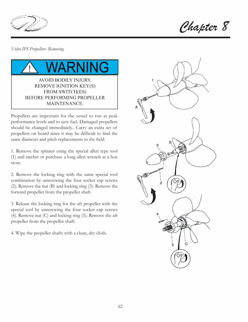
62
Chapter 8Volvo IPS Propellers- Removing
Propellers are important for the vessel to run at peak performance levels and to save fuel. Damaged propellers should be changed immediately.. Carry an extra set of propellers on board since it may be diffi cult to fi nd the same diameter and pitch replacements in the fi eld.
1. Remove the spinner using the special allen type tool (1) and ratchet or purchase a long allen wrench at a box store.
2. Remove the locking ring with the same special tool combination by unscrewing the four socket cap screws (2). Remove the nut (B) and locking ring (3). Remove the forward propeller from the propeller shaft.
3. Release the locking ring for the aft propeller with the special tool by unscrewing the four socket cap screws (4). Remove nut (C) and locking ring (5). Remove the aft propeller from the propeller shaft.
4. Wipe the propeller shafts with a clean, dry cloth.
WARNING!AVOID BODILY INJURY.
REMOVE IGNITION KEY(S) FROM SWITCH(ES)
BEFORE PERFORMING PROPELLER MAINTENANCE.

63
Cosmetic Care & MaintenanceVolvo IPS Propellers- Installing
WARNING!AVOID BODILY INJURY!
ALWAYS REMOVE KEYS FROM IGNITION SWITCHES BEFORE
BEGINNING PROPELLER MAINTENANCE.
Reassembly of the dual propeller unit requires that the propeller shaft be clean to start and the proper lubricants be applied to the unit.
1. Appy a water-resistant grease such as Volvo # 828250 to the propeller shaft splines.
2. Install the aft propeller. Screw on the aft nut (C) and hand tighten until it reaches the end of its travel. Install the locking ring (5). Tighten the locking ring with the special tool and the four socket cap screws (4). Torque from 17.5 to 20.5 ft. lbs.
3. Install the forward propeller on the propeller shaft. Screw on nut (A) by hand and install locking ring (3).Tighten the locking ring with the special tool and the four socket cap screws. Torque from 17.5 to 20.5 ft. lbs.
TIGHTEN SCREW (D) UNTIL IT BOTTOMS OUTOR IT WILL NOT BE POSSIBLE TO CHANGE
THE PROPELLER WITHOUT DAMAGING THE SPINNER.
NOTICE

64
Chapter 8Typical IPS Propeller Specifi cations
Following are the propeller specifi cations for yachts using the following IPS engines:
Yacht Model Volvo Engine Model
Propeller Type
42 SC IPS 400 T546 SC IPS 500
IPS 600T4T4
52 SC IPS 600 T2Note: All propellers are Nibral Type Material

65
Cosmetic Care & MaintenanceWASHER/DRYER

66
Chapter 8 PERIODIC MAINTENANCE

67
Cosmetic Care & MaintenanceWINDLASS
The typical windlass needs periodic maintenance to keep it in top running condition. Every 6 months the manufacturer recommends that the unit be disassembled and all the above deck parts be washed down with fresh water. Lightly oil (SAE 10) the seal, shaft, cone clutch and spline. Ensure that the base, below the gipsy, is cleaned well and the sealing ring is checked. Grease the threads on the chain pipe cover and stripper screws before re-assembly.The bearing is self lubricating and should not require servicing.Below the deck check regularly the condition of the motor/gear box and terminals and re-apply grease when necessary. The motor/gear box is two part epoxy painted to protect it against corrosion as it is constructed of steel and lives in the harshest environment on your craft. If corrosion on the motor is evident, clean and repaint with marine grade oil based enamel paint.
Note: Refer to the windlass operator’s manual for additional and more detailed maintenance information.
WARNING!TO PREVENT BODILY INJURY
REMOVE THE CHAIN FROM WINDLASS BEFORE PERFORMING MAINTENANCE.

1
Troubleshooting DIAGNOSTIC CHARTS
Note: Since this chapter covers both old and new systems a portion of the troubleshooting charts may not apply to your vessel. The following diagnostic charts will assist you in identifying minor electrical, electronic, fuel, and mechanical problems. Some of the items listed require technical training and tools. Additional up-to-date information is available in the various operation manuals as select items and their troubleshooting techniques may change since the printing of this manual and/or are too numerous to cover in this manual such as electronics components. Contact your closest Regal dealer, marine professional or internet for further information. Many times the root cause of a problem can be found using a step by step process of elimination.
AVOID BODILY INJURY AND DEATH! BEFORE PERFORMING ANY MAINTENANCE
WORK TURN OFF THE BATTERY SWITCH AND REMOVE THE KEYS
FROM THE IGNITION SWITCH.
WARNING!
CAUTION!TO AVOID BODILY INJURY!
SOME EQUIPMENT CONTAINS HIGH
VOLTAGE. USE CAUTION WHEN SERVICING
ELECTRICAL COMPONENTS.
CAUTION!TO AVOID BODILY INJURY!
USE ONLY APPROVED MARINE
REPLACEMENT PARTS.

2
Chapter 9
Factory installed antifouling paint is a top-of-the-line product but does need periodic touching up. No paint can be effective under all conditions of exposure. Man made pollution and natural occurrences can adversely affect antifouling paint performance. Extreme hot and cold water temperatures, silt, dirt, oil, brackish water and even electroylis can deminish the effects of antifouling paint.Therefore, the vessel bottom needs to be checked periodically to make sure it is clean and no growth is occurring. Lightly scrub the bottom with a soft brush to remove anything from the antifouling surface. Scrubbing is particularly important with vessels that are idle for extended periods of time. The bottom coating is most effective when the boat is being used on a continuous basis.On select yachts maintain a 1 1/2” clearance from all anodes, drive units and other underwater gear. Never paint over anodes as they will cease to work properly.Bottom paint needs to be periodically refurbished. Contact your Regal yacht dealer or a marine professional for additional information.
BOTTOM PAINT

3
Troubleshooting
PROBLEM POSSIBLE CAUSE POSSIBLE FIXNo AC power Main shore power breakers tripped
or in “off ” positionEnergize shore power inlet breakers
Dock power in “off ” position Activate dockside powerShore power cord not connected Plug in shore power cord; twist to
lockFaulty connection Repair as neededEarlier yachts-Triple breaker tripped at output of isolation transformer
Repair as needed. Reset breakers
Later yachts-ELCI breaker tripped Repair as needed. Reset breaker.Nusiance Tripping- Main ELCI Component causing excessive draw Repair/Replace part. Reset ELCINo power to AC outlets and/or equipment
Main AC ship’s panel breakers tripped or in “off ” position
Reset or activate main breakers
Shore power cord not connected Plug in shore power cordGFCI tripped Find cause of trip. Reset GFIC
Main ship’s breaker continues to trip Faully main breaker Contact yacht authorized dealerInadequate AC power with genset running
Electrical demand greater than elec-trical output
Turn off appropriate equipment breakers to lessen load
ELECTRICAL DIAGNOSTICS (AC)

4
Chapter 9
ELECTRICAL DIAGNOSTICS (DC)PROBLEM POSSIBLE CAUSE POSSIBLE FIX
No DC (12 volt) power Battery switch in “off ” position Turn selector switch to “on” posi-tion,
Weak or dead battery Charge or replace batteryBattery not charging (engine run-ning)
Loose belt Tighten beltFaulty alternator Repair/replace alternatorFaulty volt meter Replace volt meter
Battery will not hold charge Faulty or old battery Replace battery; use exact replace-ment
12 volt equipment not working Equipment switch in “off ” position Switch to “on”positionCircuit breaker/fuse blown Reset breaker. Replace fuse.Weak or dead battery Replace batteryCorroded connection Eliminaate corrosionLoose wire Tighten connectionInternal equipment short Replace equipment component

5
Troubleshooting
ELECTRONICS- GENERAL
The Garmin electronic packages installed on present yachts are very system specifi c when troubleshooting. Each package is very unique and we could not cover all the systems here. Therefore, refer to the vendor supplied operator’s manual for specifi c troubleshooting informa-tion related to an individual electronic component. In addition, helpful information is readily available on the internet at each vendor site for the retail customer. In-formation can be downloaded as needed with additional on-line contact and tech services available. Also, contact your closest Regal yacht dealer where you will fi nd factory trained professionals to assist you in solving more techni-cal electronic component issues.

6
Chapter 9
ELECTRONICS-CAMERA MONITORS
If a camera does not function check the following:
1. Make sure the cable is tightly connected and it is free of corrosion.
2. Check system fuses and breakers.
3. Check that the plotter is set up properly to view the camera image via the display. Check the optional equipment operation for more information.
4. The camera has no servicable parts.

7
Troubleshooting
FRESH WATER DIAGNOSTIC CHARTPROBLEM POSSIBLE CAUSE POSSIBLE FIX
Air in water system Water tank empty Fill water tank. With pump “on” bleed air from lines until water fl ows without air.
Fresh water pump cycles on and off Water system leak Locate & repair water leak.No water at sink faucet Breaker blown Reset breaker
Water tank empty Refi ll water tankSwitch turned off Turn switch to “on” positionBlocked water fi lter; pinched line Clear obstruction or straighten line;
clean water fi lterManifold valve turned off Turn on manifold valveLoose or disconnected wire Check wire connections
Low water pressure Defective fresh water pump Replace water pumpWeak pressure at transom shower Line pinched Find/Repair pinched lineWater to pump. No output. Faulty fresh water pump/pressure
switchReplace fresh water pump or pres-sure switch
Fresh water pump continues to cycle Defective pump pressure switch Replace pressure switch

8
Chapter 9
INSTRUMENT DIAGNOSTIC CHARTPROBLEM POSSIBLE CAUSE POSSIBLE FIX
No reading on gauge or gauge reads wrong
Faulty gauge Replace gaugeWiring to gauge faulty Inspect/repair wiringFaulty sender Replace sender
Gauge reads erratic Loose ground or hot wire Repair/replace wire and/or connec-tion

9
Troubleshooting
PERFORMANCE DIAGNOSTICSPROBLEM POSSIBLE CAUSE POSSIBLE FIX
Excessive vibration Material obstructing propeller Reverse engines to remove materialBent drive propeller shaft Call authorized Regal/Volvo dealerBent propeller blade Repair/replace propellerNoisy drive bearing Repair drive unitDamaged drive casting Replace damaged casting
Poor performance Trim incorrect Adjust trimUnbalanced load Adjust loadEngine problem Call authorized Regal/Volvo dealer
Engine speed/rpm is low Growth on hull Hoist vessel; clean bottomPoor quality fuel Call authorized Regal/Volvo dealerAccumulation of bilge water Check for leaksTrim tab in “up” position Check trim tab functions/pump fl uid
levels

10
Chapter 9
REFRIGERATOR DIAGNOSTIC CHARTPROBLEM POSSIBLE CAUSE POSSIBLE FIX
Refrigerator not cold Compressor will not start Turn breaker on at the main ship’s service panel
Thermostat set too high or on/off switch is in the off position
Reset thermostat or activate on-off switch
Compressor starts but does not cool fridge
Contact repair professional
Door latch not closing or door seal not seated
Adjust latch or replace seal
Condensor dirty Remove fridge/clean coils with brush or vacuum
Not running on DC Check for defective thermostat or converter, low battery
Relace thermostat, converter or bat-tery
Not running on AC Inadequate input voltage Make sure proper voltage exists on ship’s main AC panel.

11
Troubleshooting
SHORE CABLE SYSTEM

12
Chapter 9
SIRIUS MARINE WEATHER
LED STATUS
The LED at the connector panel provides valuable troubleshooting information on the status of your weather system.The LED blinks green while the system is operating normally. If the unit detects a problem, the LED blinks amber to indicate a warning or red to indicate an error. The pattern ot the LED blink is a code representing the nature of the problem. For multiple warnings/errors the codes are given in sequence with a 1.5 second pause between the indications.It is normal during the fi rst minute of initial power that the SR100 status LED shows no activity and remains off. During the second minute the status LED will start to fl ash the amber or red fault strings. Typically, during normal operation, a fl ashing green LED will occur within 90 seconds of initial power. If there is no LED indicaiton of any sort displayed after 90 seconds you should check the circuit breaker.A blinking red LED indicates an internal fault condition and a marine electronics technician should be contacted.
The following table shows the LED status codes and their meanings:
LED COLOR
LEDPATTERN
DESCRIPTION
GREEN BLINKING NORMAL OPERATION
AMBER 1 SEC ON1 SEC OFF
ANTENNAUNHOOKED
AMBER 1 SEC ON1 SEC OFF1SEC ON1SEC OFF
SEATALKCABLE
UNHOOKED
RED BLINKING I N T E R N A L FAULT

13
Troubleshooting
TACHOMETER-ELECTRONIC DIESEL

14
Chapter 9
TACHOMETER-ELECTRONIC DIESEL

15
Troubleshooting
TELEVISION DIAGNOSTIC CHARTPROBLEM POSSIBLE CAUSE POSSIBLE FIX
Screen is black. Power indicator is off.
TV breaker not activated Activate TV breaker on ship’s main service AC panel.
TV and/or DVD not turned on. Activate TV or DVD player.TV signal weak. TV antenna breaker not activated or
wrong antenna breaker in use.Activate TV antenna breaker. Check antenna switch for proper signal but-ton.
Image too light or dark. Brightness or contrast improperly adjusted.
Readjust brightness or contast to owner’s manual specifi cations.
Horizontal bars appear to fl icker, jit-ter, or shimmer on the image.
Fine function not adjusted properly. Adust fi ne function to owners manu-al specifi cations.
Vertical bars appear to fl icker, jitter or shimmer on the image.
Coarse function not adjusted prop-erly.
Adjust coarse function. Then adjust fi ne function.
Screen is blank and power indicator light is steady amber or blinks every 1/2 or 1 second.
Power management system being used.
See power saver in owner’s manual.
Image not centered on screen Horizontal or vertical adjustments off.
Readjust horizonizl or vertical con-trols.

16
Chapter 9
PROBLEM CAUSE ACTION/SOLUTIONToilet does not fl ush or fl ush perfor-mance is poor
Waste tank is full (tank indicator light on wall switch is RED)
Clog at pump inletSolid object in maceratorLow voltage
Empty waste tank before continuing to use toilet. Override full tank lock-out may cause waste tank to over-fl owClear clogCall Tecma at (800-521-3032)Check for no more than 10% de-crease in voltage when macerator is running. If voltage decreases more than this there may be wiring prob-lem
Water does not enter bowl during fl ush or water add cycle
Water supply line kinked or not con-nected
No power to water pump
Water supply has been truned off
Electronic control problem
Check that supply line is properly connected to fresh water supply. Check for kinks in water supply lineCheck that circuit breaker has not tripped, check all pump electrical connectorsCheck water supply valve at mani-foldCall Tecma at (800-521-3032)
Water livel in bowl has changed after fl ush
Flush refi ll mode has been changed Reprogram fl lush refi ll mode; see Techma owner’s manual
Water continues dripping briefl y into bowl after fl ush cycle is complete
Toilet is installed below water line with vacuum breaker in water supply line
Normal operation; if only a small amount drips from the nozzle
Bowl drains dry after fl lush Water is siphoning out of the bowl Discharge hose from macerator pump bent. Straighten hose
Wall switch does not appear to light up or does not stay lit
No power to toilet
Wall switch not properly connected to toiletWall switch has entered sleep mode
Check that breaker is not tripped.Check electrical connectors are mat-edEnsure wall switch electrical connec-tor is fully engaged at controllerWall switch enters sleep mode after 8 hours of continuous inactivity but re-mains functional. No action needed
Wall switch electronics problem Call Tecma at (800-521-3032)Toilet is inoperative and there is no lighting in the wall switch
No power to toilet Check that breaker is not tripped. Ensure all electrical connectors are mated. Call Tecma.
TOILET (TECHMA) DIAGNOSTIC CHART

17
Troubleshooting
TOILET-DIAGNOSTIC CHARTVACUFLUSH® (EARLIER MODELS)
PROBLEM POSSIBLE CAUSE POSSIBLE FIXWarer will not stay in bowl Loose clamp ring
Improper seal around fl ush ball or deris on underside of tefl on seal.Worn or damaged seal or fl ush ball
Tighten clamp ring adjusting nutLook for foreign objects at fl ush ballReplace seal or fl ush ballClean water valve or replace
Toilet overfl ows Dirt stuck in water valve seal or bad sealCam strap bent down holding valve open
Clean water valve or replace
Bend front of strap up 1/16”
Water does not enter toilet bowl properly
Low water pressureWater valve closed
Check incoming preesureClean fi lter on water valve inlet
Water leaking at water valve Loose connectionWorn or defective water valve
Tighten cap, inlet fi tting, clampReplace water valve
Water leaking at bowl rear Loose hose connectionLoose or worn vacuum breaker
Tighten connectionTighten/Replace vacuum breaker
Pump runs excessively between fl -lushes
Flush ball leaks
Vacuum line leaks
Duckbill valves in pump not sealing
Pump bellows in vacuum generator worn
See problems 1 & 2
Tighten all connections at toilet & vacuum generatorInspect all duckbill valves for poor sealingInspect for small holes or rip
Toilet will not fl ush Plugged vacuum line, vacuum pump discharge or intake lines
Duckbill valves inverted to clogged discharge line or seacock
Clear line(s)
Replace valves
Note: This informtion is for earlier yachts only

18
Chapter 9
TOILET-DIAGNOSTIC CHART VACUFLUSH® (EARLIER MODELS)
PROBLEM POSSIBLE CAUSE POSSIBLE FIXPump will not run No power
Loose or broken electric wire
Faulty motor
Check DC breakerCheck wires at pump, vacuum gen-erator, vacuum switch (B terminal connectorReplace motor
Pump will not shut off Insuffi cient vacuumExcessive vacuum leakFaulty vacuum switch
Check for 10 “ of vacuumSee pump running between fl ushesCheck by removing 1 of B wires
Pump running too slow, overheating or blowing breaker
Improper voltageLoose or broken wireDischarge line blocked causing back pressurePlugged or defective duckbill valve
Check input voltageFind & replace wireCheck lines/seacock; clean discharge lineClean or replace duckbill valve
Pump emits odor Loose or defective hose connection on pumpLoose intake or discharge fi ttings on pumpWorn, torn or punctured pump bel-lows or diaphragm
Tighten connections or replace hose
Tighten all fi ttings on pump or re-place all nipples/adapters as neededReplace pump bellows or diaphragm
Blockage between toilet and vacuum generator
Collased or kinked vacuum lineFlusing foreign objects down the toi-let
Inspect & repair vacuum linesDo not fl ush non-dissolving objects or excessive tissue down the toilet
Note: This informtion is for earlier yachts only

19
Troubleshooting
If The Motor Stops Suddenly:
1. The most common cause is a clogged hose. Try to unclog the hose with a long stick or by shaking the hose until the clogged debris clears.
2. The bag is overfi lled and fi ne dust has clogged the bag.
VACUUM CLEANING SYSTEM
3. The vacuum cleaning tools are clogged.
4. The motor (exhaust) fi lter is dirty and should be cleaned or replaced.
5. Ensure that the area around the main unit is free of clutter to provide proper amount air to the unit. This will help prevent the unit from shutting down.

20
Chapter 9
TYPICAL WINDLASS

1
Storage & Winterization
WARNING!EXPLOSION, FIRE & POLLUTION HAZARD!
DO NOT FILL FUEL TANK TO RATED CAPACITY.
LEAVE ROOM FOR EXPANSION.
Storage procedures are outlined in this chapter. These are general guidelines to follow in colder climates. Be sure to familiarize yourself with all relevant information in the owner’s packet. Special winterization procedures are necessary for the boat equipment and systems. Use the enclosed checklists to help you identify areas of concern and maintenance. These lists cover land stored boats either inside or outside.
All in all, it is best to contact your closest Regal yacht dealer or marine professional for winterization information. They possess the advanced service know how needed to tackle the more complex yacht systems.
INTRODUCTION
YOUR WARRANTY DOES NOT COVER
DAMAGE TO YOUR BOAT IF IT IS NOT PROPERLY STORED AND WINTERIZED.
CHECK WITH A REGAL DEALER ORMARINE PROFESSIONAL ABOUTWINTERIZATION PROCEDURES.
NOTICE
NOTICEREMOVE ALL BATTERIES
WHEN VESSEL IS STORED FOR EXTENDED PERIODS

2
Chapter 10
BOAT
Check hull bottom for any fi berglass damage. Repair as needed.
Apply a coat of wax to hull and deck surfaces.
Pour a pint of 50/50 antifreeze into bilge pump.
Remove batteries. Trickle charge over extended periods. Do not set batteries on cement. Use wood blocks.
Remove all loose gear from boat such as life jackets, etc. Inspect and store in cool, dry environment.
Remove drain plug. Clean drain plug hole of debris as needed. Enclose drain plug in plastic bag and tie to steering wheel.
Drain the waste system per instructions in this chapter.Make sure bow is higher than stern to permit proper drainage.
Clean all upholstery and store so it breathes.
Conduct a visual inspection to ensure boat is balanced properly. Bow should sit slightly up especially if outside.
Cover boat with tarp. Tie down for wind protection if outside. Prop tarp up as needed to provide proper ventilation. Be sure not to cover up the fuel vents.
Drain the fresh water system per instructions in this chapter.
Send in appropriate equipment for calibration such as the automatic fi re extinguisher canister or CO detectors.
Never use blocking to support the hull bottom as structural hull damage may occur to the vessel.
Run engine. Pour a fuel stabilizer/conditioner in the fuel tank. Allow time for it to circulate through the fuel system. Top off fuel tanks to help prevent condensation.
Change all engine fl uids as referenced in the engine manufacturer’s owners manual.
Drain cooling and exhaust system or have a marine professional “pickle” the engine with antifreeze and rust preventative.
Spray all exterior parts with a rust preventative.
The propulsion systems on your yacht are complex in scope. In colder climates, it is recommended that your Regal yacht dealer winterize your boat’s engines. Regal dealers have undergone extensive factory training covering the Regal yacht product line. Also, the dealer is equipped with the parts and tools to perform a care free winterization procedure.
DECOMMISSIONING CHECKLIST ENGINES
3
Storage & WinterizationGENERAL NOTES ON ANTIFREEZE
Engine cooling fl uids must be replaced with a marine antifreeze solution; mix antifreeze according to directions for the lowest expected temperature. The above method is much more reliable than just draining the engines and manifolds because sometimes pockets of water can form which can freeze in cold temperatures and cause engine damage. Draining the system fosters rust in engine parts. Historically, antifreeze was originally made with methanol. It was because of its chemical nature to escape into the atmosphere and a high corrosion factor on engine metals that it was replaced.Today, ethylene glycol is used in auto and marine engine applications because of its positive thermal properties. On the downside ethylene glycol contains silicate rust inhibitors that can clog up marine heat exchanger surfaces. This is why it is so important to follow the engine manufacturer maintenance schedules which include changing the antifreeze periodically. In addition, the unpleasant odor of antifreeze is caused by tolytriazole which also contributes to it being environmentally hazardous. Notwithstanding, ethylene glycol is poisonous to the human body along with animals. Therefore, it cannot be used in potable marine water systems.Propulene glycol is considerably less toxic and retail products are labeled as “non-toxic antifreeze”. It is the product of choice for marine water and waste tanks in freezing climates. It is available at marinas, RV dealerships, and retail marine outlets.
NOTICEUSE A SPECIAL NON-TOXIC ANTIFREEZEIN THE FRESH WATER & WASTE SYSTEM
WHICH IS AVAILABLE AT RV AND MARINE DEALERS.
DO NOT USE AN AUTOMOTIVE TYPE ANTIFREEZE. IT CAN BE HIGHLY
POISONOUS AND CORROSIVE.
IPS DRIVE UNITS
Since the IPS drive units are located under the vessel it makes good sense to use a Regal yacht dealer to ensure the units are winterized and have their seasonal maintenance. The yacht dealer can check all drive related systems along with the installed propellers. This is a great time to have the propellers checked for balance and knicks.Also, when the the propellers and hardware are off the propeller shaft and seals can be checked for vacuum and pressure along with touching up the drive unit.Refer to your Volvo IPS operator’s manual for a specifi c drive information and maintenance schedules.

4
Chapter 10AIR CONDITIONING:
There are several methods of winterization; some work better than others. The various methods employed using a 50/50 biodegradable antifreeze/water solution are: 1. Pumping of antifreeze solution into the overboard thru-hull fi tting, and discharging through the intake thru-hull fi tting.
2. Use of the seawater pump to move antifreeze solution through the system and discharging through the overboard thru-hull fi tting. Close the seacock, remove the hose for the strainer outlet, raise the hose above the AC pump ( to prevent lose of prime) and pour in antifreeze solution. Pump solution through system. The strainer and hose to seacock will also need to be drained.
3. Use of pressurized air to force water from the intake through the overboard discharge.
Note: Any method that causes the antifreeze solution to fl ow downward is the method of choice. By this means, the antifreeze solution will displace any water trapped and eiliminate the possibility of freezing in hidden areas. In addition, since the seawater pump utilizes a magnetically driven impeller, the impeller whould be removed from the wet end assembly, wiped with an alcohol solution, and stored in a warm, dry area until commissioning takes place.
NOTICEFOR THE PURPOSE OF PROTECTING
THE ENVIRONMENT,DISPOSE OF ANY CONTAMINATED
ACID SOLUTIONS IN ACCORDANCE WITH
FEDERAL,STATE AND/OR LOCALREGULATIONS.
FUEL TANK
Fill the fuel tank to minimize condensation but do not overfi ll. Leave enough space for fuel to expand and add a fuel stabilizer to diesel prior to storage following the manufacturer’s recommended procedures.
BATTERIES:
Remove the batteries and check the electrolyte level. Store in a cool, dry place. Add distilled water as necessary to top off the battery. Monthly recharging or continuous trickle charging should be done to insure the battery life during storage. Do not store a battery on cement as it may discharge.

5
Storage & WinterizationTELEVISION:
The television manufacturer recommends that the unit be removed from the vessel in freezing climates. To remove the fl at screen do the following:
1. Pull out the power plug from the rear of the television.
2. Unscrew the antenna cable.
3. While someone holds the fl at screen, remove the screws that hold the television to the bracket.
4. Do not touch the fl at screen or push in on it while trying to remove the unit as component damage may result.
5. Remove the television and store at room temperature.

6
Chapter 10WASHER/DRYER

7
Storage & WinterizationWASTE/TOILET SYSTEM:
1. Pump out waste holding tank, fl ush the tank with fresh water and pump out again.
2. With non-toxic propylene glycol antifreeze in the fresh water tank, operate head until antifreeze fl ows into bowl of each head. Allow time between fl ushes for the vacuum to build up.
3. Operate macerator until antifreeze has a steady fl ow coming from the discharge fi tting. Pour non-toxic propylene glycol antifreeze solution in head and fl ush head as needed to produce enough fl ow to winterize the macerator.
4. Leave at least 2 gallons of non-toxic propylene glycol antifreeze solution in the holding tank during storage.
NOTICEUSE A SPECIAL NON-TOXIC ANTIFREEZEIN THE FRESH WATER & WASTE SYSTEM
WHICH IS AVAILABLE AT RV AND MARINE DEALERS.
DO NOT USE AN AUTOMOTIVE TYPE ANTIFREEZE. IT CAN BE HIGHLY
POISONOUS AND CORROSIVE.

8
Chapter 10WATER SYSTEM-FRESH
1. Turn on the fresh water pump switch.
2. Open all faucets including transom shower and allow tank to empty.
3. Drain the water heater; shut off water pump switch.
4. Mix nontoxic antifreeze with water in accordance with the manufacturer’s recommendations.
5. Pour solution into the fresh water tank.
6. Turn on fresh water pump switch.
7. Open each cold water faucet one by one beginning with the one furthest away from the tank and purge the system until a steady stream fl ows from the faucet. Then close the faucet.
8. Repeat step 7 for hot water faucets.
9. Shut off water pump switch.
10. Pour a quart of antifreeze into shower drain. Run the shower pump until a steady stream fl ows from the discharge fi tting.
11. Leave at least 2 gallons of antifreeze solution in the holding tank during storage.

1
Glossary & Index
Following is a brief list of nautical terms useful in everyday boating experiences and communications. For more detailed glossaries of nautical terminology we recommend you check your local library, the internet or a marine store for boating books.
GLOSSARY
Abeam: at right angles to the fore and aft line and off the boat
Aboard: on or in the boat
Above: the part of the boat on a bavin vessel which is above the interor of the boat
Aft, After: aft is the boat section toward the stern or back of the boat Admidships: toward the center of the boat from either side to side or rear to front Beam: the width of a boat at its widest part Bilge: the lower interior of the hull of the boat
Bitter end: the end of a line also the end of an anchor line
Bow: the front, or forward part of the boat
Bulkhead: the vertical partition or wall of a boat
Cast off: to let go or release
Chine: the line fore and aft formed by the intersection of the side and bottom of the boat
Chock: deck fi tting used to secure or guide anchor or tie lines
Cleat: deck fi tting with protruding arms around which lines are secured
Cockpit: the seating space used to accomodate passengers
Cuddy: a small cabin in the fore part of the boat
Deck: the open fl ooring surface on which crew and passengers walk

2
Chapter 11Draft: the depth from the waterline of the boat to the lowest part of the boat, which indicates how much water is required to fl oat the boat
Fathom: a measurement of depth; one fathom equals six feet
Fender: a cushion hung from the side of a boat to prevent it from rubbing against a dock or against other boats
Fend off: to push off to avoid sharp contact with dock or other vessel
Fore: the part of the boat toward the bow or front
Freeboard: the height of the top side from the waterline to the deck at its shortest point. (The distance from the sheer or gunwale to the water)
Galley: cooking area
Gunwale: rail or upper edge of the side of the boat
Hatch: an opening in the deck to provide access below
Head: toilet
Hull: the part of the hull from the deck down
IPS: inboard propulsion system by Volvo
Keel: the lowest point of a boat
Knots: a measurement of speed indicating nautical miles per hour
Lee: the side opposite that from which the wind is blowing: the side sheltered from the windLeeward: the direction toward which the wind is blowing
PFD: personal fl oatation device; required for each person aboard
Port: the left side of the boat when facing forward (an easy way to remember the difference between “port” and “starboard” is that both “port” and “left” have four letters)
Shank: the main body of an anchor
Sheer: the curve of the boat’s deck from fore to aft when seen from the side
Starboard: the right side of the boat when facing forward
Stern: the aft end of the boat
Stern drive: an inboard/outboard (IO)unit
Stringer: strengthening integral unit fastened from fore to aft inside the hull and fi berglass encapsulated for added strength: much like the skeleton system of our body
Top off: to fi ll up a tank
Transom: the vertical part of the stern.
Trim: the boat’s balance when properly loaded
Wake: the path of a boat left astern in the water

3
Glossary & Index
AAC Current 4-37 9-3AC Panel 4-45Accidents 2-20Aft Sectional Filler Cushions-(Install/Remove 7-42Air Conditioning 4-56 7-32 8-24Alcohol Myths & Facts 2-19Antenna-GPS 7-27Anchoring 6-9
BBatteries 4-13 8-27Battery Charger 4-19 5-2Battery Management Panel 4-24Battery Parallel Switch 4-22 5-5 8-31Battery Switches 4-16Battery System Breaker 4-22Bilge-Engine Compartment 8-3Bilge Pump 7-28 8-32Blower 4-2Bottom Paint 8-3 9-2Breaker Panel 4-31Breast Lines 6-6Bridge Clearance 3-8
CCabinet Care 8-4Camera Monitoring System 4-100 8-33 9-6Canvas 8-5Carbon Monoxide 2-15Carbon Monoxide Detector 2-18 7-3 8-34Cardiopulmonary Resuscitation 6-11Carpet-Cockpit 8-7 Interior 8-6 9-13Compass 7-31 8-34Corian® 8-9
DDealer Responsibilities 1-10Decommissioning 10-2Diagnostic Charts (Troubleshooting) 9-1Diesel Fuel Filter 4-8Diesel Fuel Transfer Switch 4-10Direct Current (DC) 4-13DC Panel 4-29 9-4Distress Signals 2-7Diver’s Flag 2-22Docking 6-8Dock Lines 6-6Dockside Power (Shorepower) 5-17 9-11Dockside Water Inlet 4-62Dockside Pump-Out 4-70Door (Cabin Entry) 7-4Door (Transom) 7-33Drain Plug 6-1

4
Chapter 11
EELCI 4-42Electrical 9-5 TechnicalElectronics: 9-5
Auto Pilot 4-95Depth Sounder 4-97E- Series Plotter 4-92Radar 4-94 Sirius Marine Weather 7-310 8-83 9-67Sirius Satellite Radio 4-98Emergency Shifting 5-16Engine 4-99 5-1 8-57Entertainment System 4-84Environmental Awareness 6-14Equipment Operation 7-1Exhaust 2-15
FFabrics-Interior 8-10Fenders 6-5Fiberglass Maintenance 8-11Fire Extinguishers 2-6 7-35 8-37Fires 6-11First Aid 6-11Flooring 7-13Float Plan 1-7Fresh Water System 4-60 9-7Fuel System 4-2 6-3 8-38
GGFIC 4-49 8-42Galvanic Isolator 4-43Gauges/Switch Panels 8-14Gelcoat Maintenance 8-11General Boating Safety 2-2Generator 4-51 7-37Generator Maintenance 8-39Getting Underway 6-1Glossary 11-1Gray Water System 4-68
HHatches 7-5Heater-Hot Water 4-66 7-40 8-43High Water Alarm 5-8 7-41 8-44HIN 1-5Horn 2-10Hose Reels 4-62Hull/Deck 8-17Hypothermia 6-12
IIgnition Switch 4-23 5-4Index 11-3Instruments (Gauges) 5-7 8-13 9-8International Distress Signals 2-9
JJoystick 5-12 6-8
KKnots 6-8

5
Glossary & Index
LLights 2-10 7-6
MMaintaining PFD’S 2-6Markers-For Slings 7-45Mayday 2-10Metal (Stainless Steel) 8-19Microwave 8-17Minimum Required Equipment 2-14Monitor Panel 7-9
NNavigation Aids 3-5Navigation Light Rules 2-11 5-7Navigation Rules 3-1
OOil Change System 7-46 8-16Oil Spills 2-12Overboard Discharge Pump 4-71 7-50Overloading 2-3Owner Packet 1-4Owner Responsibilities 1-11
PPersonal Flotation Devices 2-4
Plastics 8-18Plumbing Connectors 8-47Pollution Regulations 2-12Portlights 7-10Pre-departure Questionaire 6-1Propellers 5-17Propulsion 5-15Pressure Pump-Fresh Water 7-51 8-48
RRange/Stove 7-11 8-18Refrigerator 9-10Registration Information 1-10Relay (VSR) 4-17Remote Control 5-11 6-5Right-Of-Way 3-1Rules Of The Road 3-1

6
Chapter 11
TTachometer 9-13Technical Drawings TechnicalTechnical Information 12-1Television 7-17 8-51 9-15Toilet 4-68 8-55 9-16Towing 6-10Trim Tabs 4-76Transfer Pump 4-10Troubleshooting 9-1
UUnderwater Lighting 7-61 9-23Upholstery 8-21
VVHF 2-10 4-100Vacuum Cleaner System 7-18 9-19Valves-Fuel & Generator 7-251Ventilation System 4-5 5-3
Vessel Information Sheet 1-6Visual Distress Signals 2-7Volvo Joystick 5-12
WWasher/Dryer 7-20 8-65Waste System 4-68 Windlass 4-79 8-67 9-20Winterization 10-1
ZZipper Care 8-5
SSafety Labels 2-1Seacocks 4-59 4-71 8-54Seat- Helm 7-16Shorepower (See Dockside Power) Shower-Transom 4-65 7-53Shower Sump Pump 4-66 8-50Sound Producing Devices 2-10Specifi cations TechnicalSpotlight 7-56Spring Line 6-6Stainless Steel 8-19Stains 8-20Stern Line 6-6Steering 5-12Stereo/CD/DVD Player 4-90 8-51 9-68Storage 10-1Sunbrella Canvas Cleaning 8-5Sunpad/Chaise Lounge 7-57Sunroof 4-78Swim Ladder 7-58Swim Platform 2-59

1
Technical
Note that all product specifi cations, models, standard, optional equipment, systems, along with the technical information is subject to change without notice. For more information contact your nearest authorized Regal dealer. For the location of your nearest authorized dealer call 407-851-4360
or you can contact Regal through the internet at : www. regalboats.com. Your Regal dealer has received special factory training on the entire product line and his services should be employed to solve more technical problems.
A portion of the technical drawings found in this chapter are actual product drawings from the Regal factory. These drawings should be of special interest in mechanical and electrical troubleshooting. The equipment in the drawings is discussed in the various sections of this manual. Understanding specifi c systems and related drawings will go a long ways in solving problems.
TECHNICAL INFORMATION

2
Chapter 12
TYPICAL LABEL LOCATIONS
SLING
SLING
POWER SWITCH AT BOW ANCHOR WINDLASSMUST BE IN OFF POSITION
WHEN NOT IN USE.
*Note-Drawing Not To ScaleLabels & Locations Subject To Change
42 SC SHOWN

3
Technical Information
42SC SPECIFICATIONSLENGTH OVERALL W/ EXT.PLATFORM
USA42’ 4”
CE12.9 M
BEAM 13’ 4.0 MDEADRISE 18 DEGREESAPPROXIMATE DRY WEIGHT W/ TWVOLVO IPS 400 20,500 LBS. 9298.0 KG
APPROXIMATE BRIDGE CLEARANCE TO TOP OF RADAR 12’ 4” 3.8 MCOCKPIT DEPTH 38” 0.9 MAPPROXIMATE DRAFT 41” 1.04 MFUEL CAPACITY 276 GALS 1044 LWATER CAPACITY * 70 264 LWASTE CAPACITY * 40 GALS 151 LPERSONS CAPACITY YACHT CERTIFIED TBDMAXIMUM LOAD RECOMMENDED; PERSONS & GEAR
1502 KG

4
Chapter 12
46SC SPECIFICATIONSLENGTH OVERALL W/ EXT.PLATFORM
USA46’
CE14.02 M
BEAM 14’ 4.27 MDEADRISE 20 DEGREESAPPROXIMATE DRY WEIGHT W/ TWVOLVO IPS 500
25,300 LBS. 11,475 KG
APPROXIMATE BRIDGE CLEARANCETO TOP OF RADAR
12’ 10” 3.91 M
COCKPIT DEPTH 38” 0.97 MCOCKPIT STORAGE 100 CU.FT 2.8 CU.MAPPROXIMATE DRAFT 42” 1.07 MFUEL CAPACITY 328 GALS 1242.0 LWATER CAPACITY 101 GALS 382 LWASTE CAPACITY 48 GALS 182 LPERSONS CAPACITY YACHT CERTIFIED 14MAXIMUM LOAD RECOMMENDED; PERSONS & GEAR
1777 KG

5
Technical Information
TYPICAL VACUUM TYPE PLUMBING LAYOUT(EARLIER MODELS)
VACUUM TOILET
VACUUM GENERATORPUMP OUT DECK FITTING
WATER/WASTE MONITOR
WASTE HOLDING TANK
OPTIONAL OVERBOARD DISCHARGE PUMP (MACERATOR)
VENT FILTER

6
Chapter 12 TYPICAL VACUUM TYPE PLUMBING LAYOUT
(LATER MODELS)WASTE SYSTEM-LATER MODELS
1. Toilet Bowl2. Solenoid Valve3. Fresh Water Pressure Pump4. System Vent5. Holding Tank6. Fresh Water Tank (System can also run from dockside water supply)
5 6
Forward Head Aft Head
To 12 Volt MainControl PanelFwd. Head Breaker
To 12 Volt MainControl Panel Aft Head Breaker
To 12 Volt MainControl PanelFresh Water Pressure PumpBreaker
Wall Control Panel

7
Technical Information
46SC Deck Overview46SC Cabin Overview
42/46 DECK/CABIN FEATURES
SUNPAD/CHAISELOUNGER
WINDLASSCUT-OUT
SWITCH
BATTERYSWITCHES
HELMELECTRONICS
DOCKSIDEPOWERINLET
HELM SEAT
DOCKSIDEWATERINLET
WINDLASS
FORWARDSTATEROOM
MIDSTATEROOM/HEAD
GALLEY
HEAD
SALONDINETTE/SLEEPER
ENGINECOMPARTMENT(BILGE)
INNERSPRINGMATTRESS
WINDSHIELD
SWIM PLATFORM
TRANSOM GATE
CABIN ENTRANCE DOOR
*NOTE: NOT TO SCALE/SELECT FEATURES SHOWN
HATCH
INSPECTIONHATCH
COOLCOCKPIT
ULTRALOUNGE
ELONGATED HULL WINDOWS

8
Chapter 12
TECHNICAL DRAWINGS

Technical Information
12-942-46 MAIN SHIP’S AC PANEL REGAL PART# 442014

Technical Information
12-1042-46 MAIN SHIP’S AC PANEL EURO VERSION REGAL PART# 442013

Technical Information
12-1142-46 MAIN SHIP’S DC PANEL REGAL PART# 442015

Technical Information
12-1242-46 BATTERY MANAGEMENT PANEL W/ BREAKER SIZES PART# 412510

Technical Information
12-1342-46 BATTERY MANAGEMENT PANEL (REAR VIEW) PART# 412510

Technical Information
12-1442-46 BREAKER PANEL W/BREAKER SIZES PART# 446133

Technical Information
12-1542-46 MAIN SHIP’S AC/DC PANEL W/ BREAKER SIZES PART# 442014

Technical Information
12-1642-46 MAIN SHIP’S AC/DC PANEL W/ BREAKER SIZES LISTED

Technical Information
12-1742 SC DECK HARNESS ROUTING

Technical Information
12-1842 SC HULL HARNESS ROUTING 1

Technical Information
12-1942 SC HULL HARNESS ROUTING 2
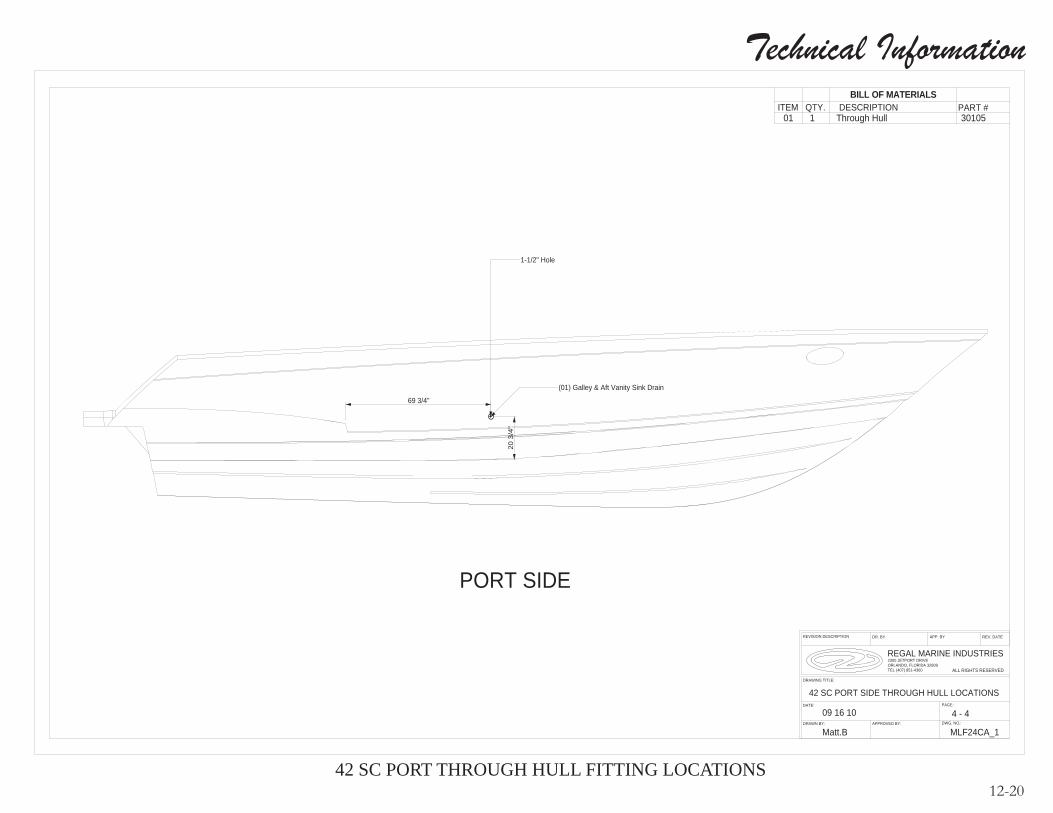
Technical Information
12-2042 SC PORT THROUGH HULL FITTING LOCATIONS
PART #
42 SC PORT SIDE THROUGH HULL LOCATIONS
QTY.
Matt.B
DESCRIPTION
APPROVED BY:DRAWN BY:
APP. BY
1
BILL OF MATERIALS
ALL RIGHTS RESERVED
REV. DATEDR. BYREVISION DESCRIPTION
ITEM3010501
PAGE:
DWG. NO.:
DATE:
DRAWING TITLE:
2300 JETPORT DRIVEORLANDO, FLORIDA 32809TEL (407) 851-4360
09 16 10
MLF24CA_1
4 - 4
Through Hull
REGAL MARINE INDUSTRIES
(01) Galley & Aft Vanity Sink Drain
1-1/2" Hole
20 3
/4"
69 3/4"
PORT SIDE

Technical Information
12-2142 SC STARBOARD THROUGH HULL FITTING LOCATIONS

Technical Information
12-22
C.W.
APPROVED BY:
DATE:
REGAL MARINE INDUSTRIES
ALL RIGHTS RESERVED
DR. BY
Matt.B
REVISION DESCRIPTION
PAGE:
1 - 2
C.W.
APP. BY
REVISIDED LIFT LOCATIONS
J.A.
5-23-11J.A.
2300 JETPORT DRIVEORLANDO, FLORIDA 32809TEL (407) 851-4360
6-13-11
REV. DATE
DWG. NO.:
DRAWING TITLE:
REVISIDED LIFT LOCATIONS
DRAWN BY:
42 SC LIFT STRAP LOCATION
09.0610
MLF25D
84.0
22.0 173.0
REGAL MARINIE (RGM)42 SCLift Strap Location
42 SC SLING LOCATIONS
WING
NOTICE TO BOAT OWNER/LIFT OPERATOR: BEFORE LIFTING BOAT PLACE FENDER OR BLOCK BETWEEN STRAP AND HULL JUST UNDER THE SWIM PLATFORM SIDE WING (BOTH PORT AND STBD.) TO RELIEVE STRAP PRESSURE ON WING WHEN LIFTING BOAT. WHEN FENDER POSITIONED CORRECTLY STRAP SHALL NOT PUT PRESSURE ON SIDE WING WHEN FULL WEIGHT IS APPLIED.
NOTICEBOAT OWNER-LIFT OPERATOR
Before lifting boat place a fendor or block between strap and hull just under the swim platform side wing (Both port and starboard) to relieve strap pressure on wing when lifting boat. When fender or block is positioned correctly strap will not put pressure on side wing when full weight is applied. FAILURE TO FOLLOW THE ABOVE INSTRUCTIONS MAY CAUSE FIBERGLASS DAMAGE WHICH IS NOT COVERED UNDER THE REGAL LIMITED WARRANTY.

Technical Information
12-2342 SC A/C HULL RUNS

Technical Information
12-2442 SC A/C DECK RUNS

Technical Information
12-2542 SC V-BERTH HOT WATER PLUMBING RUNS

Technical Information
12-2642 SC V-BERTH COLD WATER PLUMBING RUNS

Technical Information
12-2742 SC PLUMBING DRAIN RUNS
BILL OF MATERIALS
01ITEM
WLFHL20BDESCRIPTION PART #
1 Water Tank FloorQTY.
PROPRIETARY AND CONFIDENTIAL
DR. BY
DATE:
MLF23C - 5DWG. NO.:
DRAWING TITLE:
Matt.BDRAWN BY:
THE INFORMATION CONTAINED IN THIS DRAWING IS THE SOLE PROPERTY OF REGAL MARINE INDUSTRIES. ANY REPRODUCTION IN PART OR AS WHOLE WITHOUT THE WRITTEN PERMISSION OF REGAL MARINE INDUSTRIES IS PROHIBITED
SHEET:
REVISION DESCRIPTION APP. BY
FILE NAME
APPROVED BY:
REGAL MARINE INDUSTRIES
ALL RIGHTS RESERVED
SCALE:
REV. DATE
4060 LF Drain Runs
104.05.10
2300 JETPORT DRIVEORLANDO, FLORIDA 32809TEL (407) 851-4360Sink Runs Overboard ( 1" Wast Hose )
Sink Runs Overboard ( 1" Wast Hose )
Shower Box
FWD Toilet ( 1 1/2" Wast Hose )
Shower Box
Shower Drain ( 1 1/2" XHD )
FWD Sink ( 1" XHD )
Head Drain ( 1 1/2" XHD )
FWD Head Sink ( 1" Wast Hose )
AFT Toilet ( 1 1/2" Wast Hose
To AFT Shower Box ( 5/8" XHD )
Pump Out ( 1 1/2" Waste Hose )
AFT A/C Drain( 1/2" XHD )
FWD Shower Box( 5/8" XHD )
AFT BilgeFWD Bilge
Note: Double Fittings Putout
Shower Box Drain ( 1 1/2" XHD )
Manifold
Shower Box Drain / Through Fire Wall
AFT Shower
FWD Shower Box
AFT A/C Drain
Drain
Drain
WAIST TANKWATER TANK
FWD Bilge
Drain
A/C
AFT Bilge
42 SC Drain Runs
Note: FWD Head Drain & FWD Shower connected togeather with a T
Vent ( 1" Wast Hose )
A/C

Technical Information
12-2842 SC PORT HULL HOT AND COLD PLUMBING RUNS (PROFILE VIEW)

Technical Information
12-2942 SC PORT HULL HOT WATER PLUMBING RUNS

Technical Information
12-3042 SC OVERVIEW COLD PLUMBING RUNS

Technical Information
12-3142 SC SUMP LAYOUT

Technical Information
12-3242 SC FUEL TANK RUNS

Technical Information
12-3346 SC (ONLY) ISOLATION TRANSFORMER CIRCUITRY (EARLIER VESSELS ONLY)

Technical Information
12-3446 SC (ONLY) EURO VERSION ISOLATION TRANSFORMER CIRCUITRY (EARLIER VESSELS ONLY)

Technical Information
12-3546 SC DC GROUND CIRCUITRY

Technical Information
12-3646 SC TRIM TAB SWITCH CIRCUITRY

Technical Information
12-3746 SC TYPICAL BATTERY MANAGEMENT PANEL CIRCUITRY

Technical Information
12-3846 SC TYPICAL GFCI CIRCUITRY
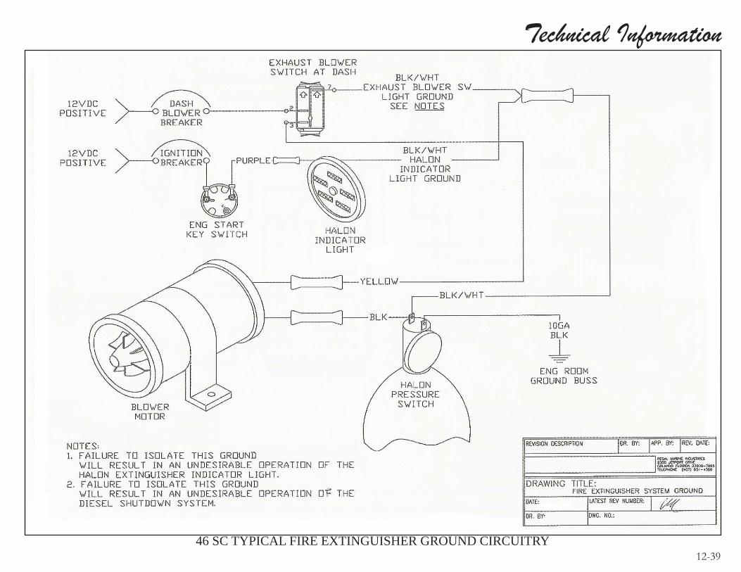
Technical Information
12-3946 SC TYPICAL FIRE EXTINGUISHER GROUND CIRCUITRY

Technical Information
12-4046 SC TYPICAL TWIN VOLVO DIESEL ENGINE FIRE EXT. SHUTDOWN

Technical Information
12-4146 SC BATTERY SWITCH CIRCUITRY

Technical Information
12-4246 SC ELECTRONICS CIRCUITRY OVERVIEW

Technical Information
12-4346 SC WIPER CIRCUITRY OVERVIEW