Embed Size (px)
Citation preview
Chapter 4: Troubleshooting & Maintenance 1
Training Workbook: HAPPY HCD-1501 Operation and MaintenanceEducation Department
Training:
HAPPY HCD-1501 Operations & Maintenance
Chapter 4: Troubleshooting and Maintenance– Basic Troubleshooting/ Sewing Interruptions
• Troubleshooting thread breaks 2
– Maintenance and Upkeep• Oiling: daily and weekly schedules 3• Cleaning (rotary hook area)
– Maintenance/Repair Techniques• Rotary hook timing 4• Hook retainer adjustment 7• Setting presser foot height 8• Setting adjusting needle depth 10• Error code list and remedies 12
Updated April 15, 2010: Added error code list
Chapter 4: Troubleshooting & Maintenance 2
Training Workbook: HAPPY HCD-1501 Operation and MaintenanceEducation Department
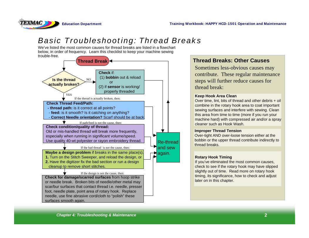
Basic Troubleshooting: Thread BreaksWe’ve listed the most common causes for thread breaks are listed in a flowchart below, in order of frequency. Learn this checklist to keep your machine sewing trouble-free.
Is the threadactually broken?
NO
Check if:(1) bobbin out & reload
or (2) if sensor is working/
properly threadedYES
Check Thread Feed/Path:- thread path: is it correct at all points? - feed: is it smooth? Is it catching on anything?- Correct Needle orientation? Scarf should be at back.
Re-threadand sewagain.
Thread Break
Check condition/quality of thread:Old or mis-handled thread will break more frequently,especially when running in significant volume/speed.Use quality 40-wt polyester or rayon embroidery thread.
If path/feed is not the cause, then:
If the thread is actually broken, then:
Maybe a design problem if breaks in the same place(s).1. Turn on the Stitch Sweeper, and reload the design, or 2. Have the digitizer fix the bad section or run a design
cleanup to remove short stitches.
If the bad thread is not the cause, then:
Check for damage/scarred surfaces from hoop strikeor needle break. Broken bits of needle/other metal mayscar/bur surfaces that contact thread i.e. needle, presserfoot, needle plate, point area of rotary hook. Replaceneedle, use fine abrasive cord/cloth to “polish” thesesurfaces smooth again.
If the design is not the cause, then:
Thread Breaks: Other CausesSometimes less-obvious causes maycontribute. These regular maintenance steps will further reduce causes for thread break:Keep Hook Area CleanOver time, lint, bits of thread and other debris + oilcombine in the rotary hook area to coat importantsewing surfaces and interfere with sewing. Cleanthis area from time to time (more if you run yourmachine hard) with compressed air and/or a spraycleaner such as Hook Wash.
Improper Thread TensionOver-tight AND over-loose tension either at thebobbin or the upper thread contribute indirectly tothread breaks.
Rotary Hook TimingIf you’ve eliminated the most common causes, check to see if the rotary hook may have slippedslightly out of time. Read more on rotary hooktiming, its significance, how to check and adjustlater on in this chapter.
Chapter 4: Troubleshooting & Maintenance 3
Training Workbook: HAPPY HCD-1501 Operation and MaintenanceEducation Department
General Maintenance and Upkeep
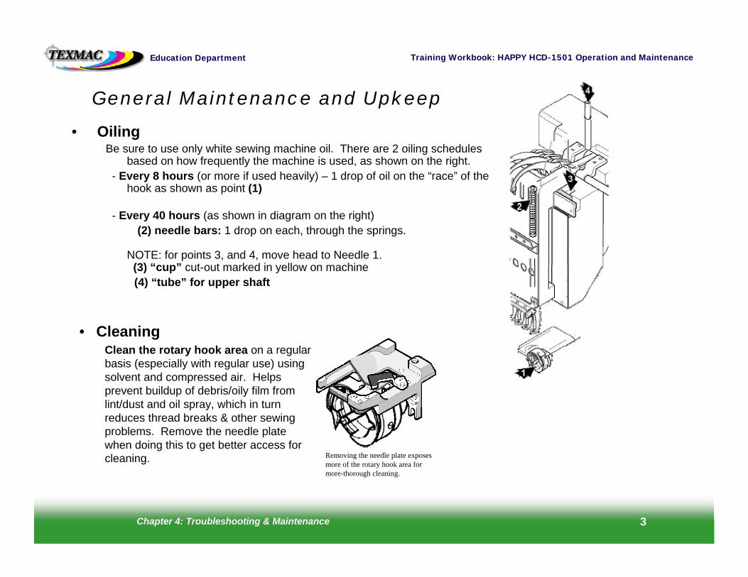
• OilingBe sure to use only white sewing machine oil. There are 2 oiling schedules
based on how frequently the machine is used, as shown on the right.- Every 8 hours (or more if used heavily) – 1 drop of oil on the “race” of the
hook as shown as point (1)
- Every 40 hours (as shown in diagram on the right)(2) needle bars: 1 drop on each, through the springs.
NOTE: for points 3, and 4, move head to Needle 1.(3) “cup” cut-out marked in yellow on machine(4) “tube” for upper shaft
• CleaningClean the rotary hook area on a regular basis (especially with regular use) using solvent and compressed air. Helps prevent buildup of debris/oily film from lint/dust and oil spray, which in turn reduces thread breaks & other sewing problems. Remove the needle plate when doing this to get better access for cleaning. Removing the needle plate exposes
more of the rotary hook area for more-thorough cleaning.
Chapter 4: Troubleshooting & Maintenance 4
Training Workbook: HAPPY HCD-1501 Operation and MaintenanceEducation Department
Checking Rotary Hook Timing and ClearanceIf you suspect that your rotary hook timing is off, you can check this by following these steps:
1. Power the machine on and allow it to continue to the main drive screen.2. Select needle seven (7). Do this using the keys on the control panel
3. Remove the needle plate and bobbin case . Do this by loosening each of the two (2) flatheadscrews with an offset screwdriver (provided in the machine’s toolkit)
3. Remove the bobbin case.
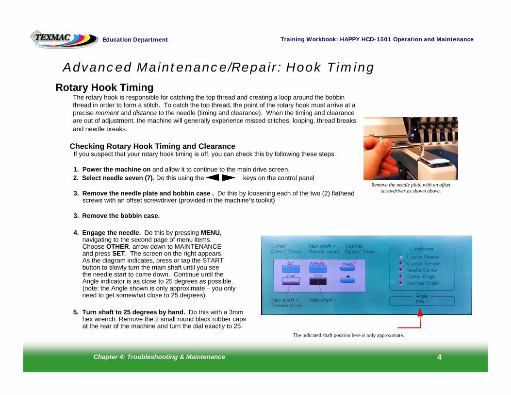
4. Engage the needle. Do this by pressing MENU, navigating to the second page of menu items. Choose OTHER, arrow down to MAINTENANCE and press SET. The screen on the right appears.As the diagram indicates, press or tap the STARTbutton to slowly turn the main shaft until you seethe needle start to come down. Continue until theAngle indicator is as close to 25 degrees as possible.(note: the Angle shown is only approximate – you onlyneed to get somewhat close to 25 degrees)
5. Turn shaft to 25 degrees by hand. Do this with a 3mm hex wrench. Remove the 2 small round black rubber capsat the rear of the machine and turn the dial exactly to 25.
Advanced Maintenance/Repair: Hook Timing
Rotary Hook TimingThe rotary hook is responsible for catching the top thread and creating a loop around the bobbin thread in order to form a stitch. To catch the top thread, the point of the rotary hook must arrive at a precise moment and distance to the needle (timing and clearance). When the timing and clearance are out of adjustment, the machine will generally experience missed stitches, looping, thread breaks and needle breaks.
Remove the needle plate with an offset screwdriver as shown above.
The indicated shaft position here is only approximate.
Chapter 4: Troubleshooting & Maintenance 5
Training Workbook: HAPPY HCD-1501 Operation and MaintenanceEducation Department
Inspecting Rotary Hook Timing and Clearance (continued)
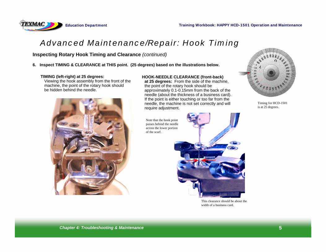
6. Inspect TIMING & CLEARANCE at THIS point. (25 degrees) based on the illustrations below.
Advanced Maintenance/Repair: Hook Timing
This clearance should be about the width of a business card.
TIMING (left-right) at 25 degrees:Viewing the hook assembly from the front of themachine, the point of the rotary hook shouldbe hidden behind the needle.
HOOK-NEEDLE CLEARANCE (front-back) at 25 degrees: From the side of the machine, the point of the rotary hook should be approximately 0.1-0.15mm from the back of the needle (about the thickness of a business card). If the point is either touching or too far from the needle, the machine is not set correctly and will require adjustment.
Note that the hook point passes behind the needle across the lower portion of the scarf.
Timing for HCD-1501 is at 25 degrees.
Chapter 4: Troubleshooting & Maintenance 6
Training Workbook: HAPPY HCD-1501 Operation and MaintenanceEducation Department
To Adjust Rotary Hook Timing It is important that all owners learn to inspect rotary hook timing, but the actual adjustment requires some precision and skill, and should not be attempted if you do not feel comfortable doing this. If in doubt, consult appropriate support staff before continuing.
1. Prepare the Machine. Do this by completing steps 1-7 on page 6 of this chapter.
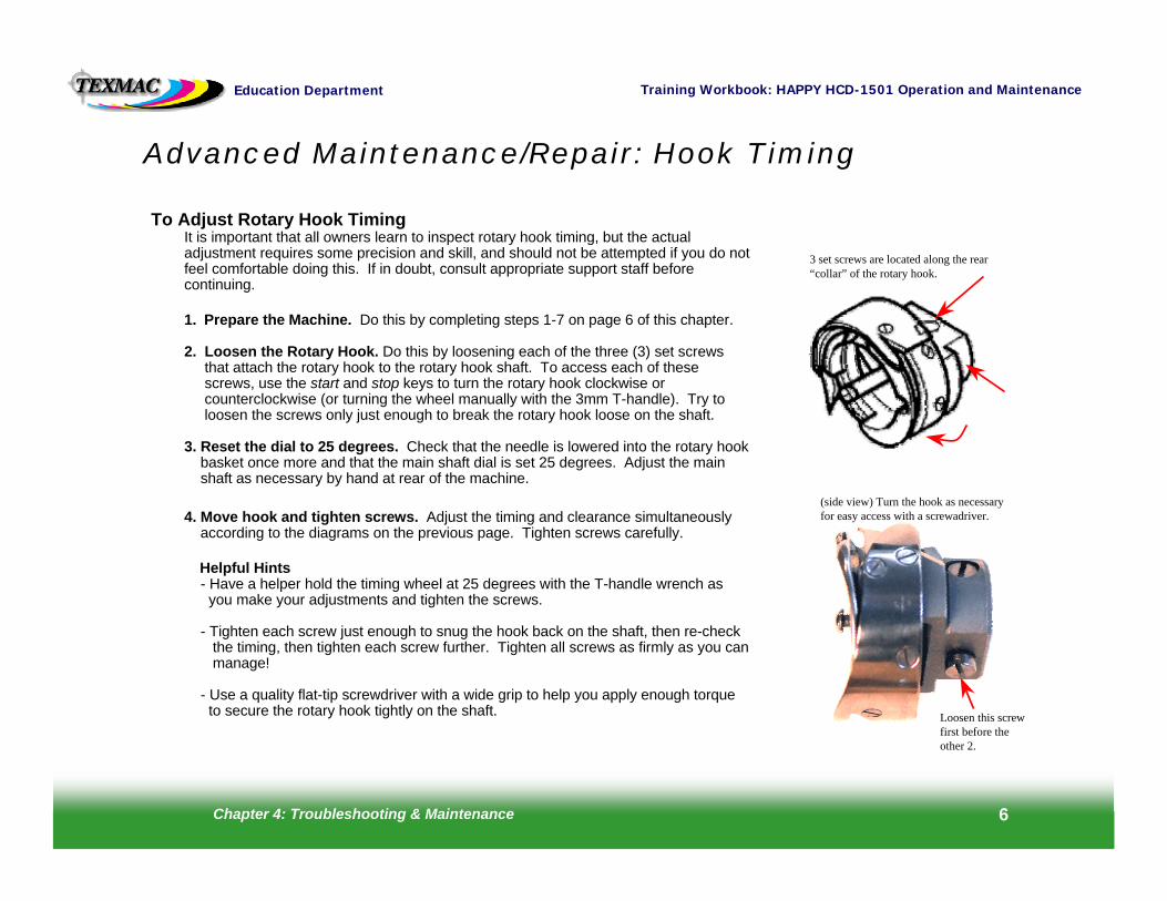
2. Loosen the Rotary Hook. Do this by loosening each of the three (3) set screws that attach the rotary hook to the rotary hook shaft. To access each of these screws, use the start and stop keys to turn the rotary hook clockwise or counterclockwise (or turning the wheel manually with the 3mm T-handle). Try toloosen the screws only just enough to break the rotary hook loose on the shaft.
3. Reset the dial to 25 degrees. Check that the needle is lowered into the rotary hook basket once more and that the main shaft dial is set 25 degrees. Adjust the main shaft as necessary by hand at rear of the machine.
4. Move hook and tighten screws. Adjust the timing and clearance simultaneously according to the diagrams on the previous page. Tighten screws carefully.
Helpful Hints- Have a helper hold the timing wheel at 25 degrees with the T-handle wrench as you make your adjustments and tighten the screws.
- Tighten each screw just enough to snug the hook back on the shaft, then re-check the timing, then tighten each screw further. Tighten all screws as firmly as you canmanage!
- Use a quality flat-tip screwdriver with a wide grip to help you apply enough torqueto secure the rotary hook tightly on the shaft.
Advanced Maintenance/Repair: Hook Timing
3 set screws are located along the rear “collar” of the rotary hook.
(side view) Turn the hook as necessary for easy access with a screwadriver.
Loosen this screw first before the other 2.
Chapter 4: Troubleshooting & Maintenance 7
Training Workbook: HAPPY HCD-1501 Operation and MaintenanceEducation Department
Hook Retainer Adjustment
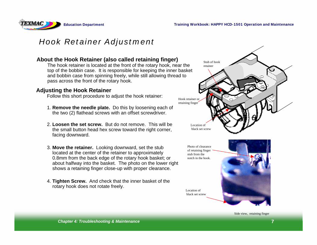
About the Hook Retainer (also called retaining finger)The hook retainer is located at the front of the rotary hook, near thetop of the bobbin case. It is responsible for keeping the inner basket and bobbin case from spinning freely, while still allowing thread to pass across the front of the rotary hook.
Hook retainer or retaining finger
Adjusting the Hook RetainerFollow this short procedure to adjust the hook retainer:
1. Remove the needle plate. Do this by loosening each of the two (2) flathead screws with an offset screwdriver.
2. Loosen the set screw. But do not remove. This will be the small button head hex screw toward the right corner, facing downward.
3. Move the retainer. Looking downward, set the stub located at the center of the retainer to approximately 0.8mm from the back edge of the rotary hook basket; or about halfway into the basket. The photo on the lower right shows a retaining finger close-up with proper clearance.
4. Tighten Screw. And check that the inner basket of the rotary hook does not rotate freely.
Location ofblack set screw
Stub of hook retainer
Location ofblack set screw
Side view, retaining finger
Photo of clearance of retaining finger stub from the notch in the hook.
Chapter 4: Troubleshooting & Maintenance 8
Training Workbook: HAPPY HCD-1501 Operation and MaintenanceEducation Department
Inspecting Presser Foot HeightFollow this procedure to check proper presser foot height:
1. Turn the machine on. Then press the Set button.
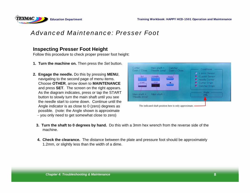
2. Engage the needle. Do this by pressing MENU, navigating to the second page of menu items. Choose OTHER, arrow down to MAINTENANCEand press SET. The screen on the right appears.As the diagram indicates, press or tap the STARTbutton to slowly turn the main shaft until you seethe needle start to come down. Continue until theAngle indicator is as close to 0 (zero) degrees aspossible. (note: the Angle shown is approximate
– you only need to get somewhat close to zero)
3. Turn the shaft to 0 degrees by hand. Do this with a 3mm hex wrench from the reverse side of the machine.
4. Check the clearance. The distance between the plate and pressure foot should be approximately 1.2mm, or slightly less than the width of a dime.
Advanced Maintenance: Presser Foot
The indicated shaft position here is only approximate.
Chapter 4: Troubleshooting & Maintenance 9
Training Workbook: HAPPY HCD-1501 Operation and MaintenanceEducation Department
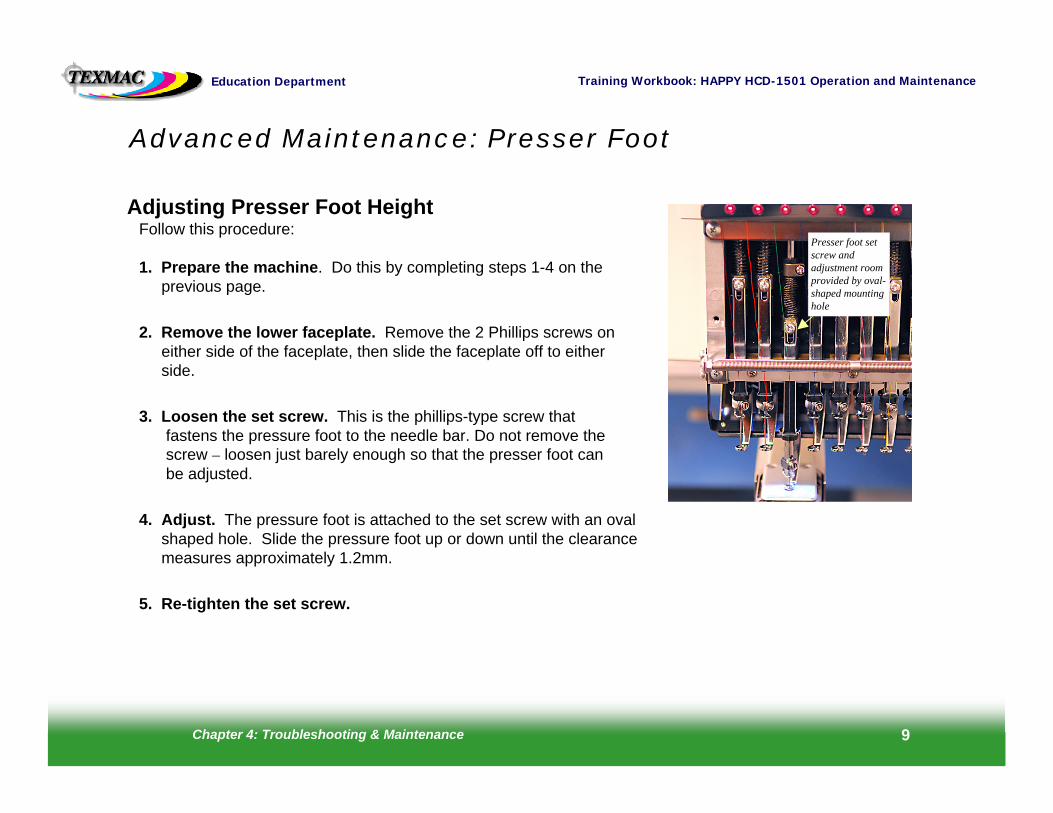
Adjusting Presser Foot HeightFollow this procedure:
1. Prepare the machine. Do this by completing steps 1-4 on theprevious page.
2. Remove the lower faceplate. Remove the 2 Phillips screws oneither side of the faceplate, then slide the faceplate off to eitherside.
3. Loosen the set screw. This is the phillips-type screw thatfastens the pressure foot to the needle bar. Do not remove thescrew – loosen just barely enough so that the presser foot canbe adjusted.
4. Adjust. The pressure foot is attached to the set screw with an ovalshaped hole. Slide the pressure foot up or down until the clearancemeasures approximately 1.2mm.
5. Re-tighten the set screw.
Advanced Maintenance: Presser Foot
Presser foot set screw and adjustment room provided by oval-shaped mounting hole
Chapter 4: Troubleshooting & Maintenance 10
Training Workbook: HAPPY HCD-1501 Operation and MaintenanceEducation Department
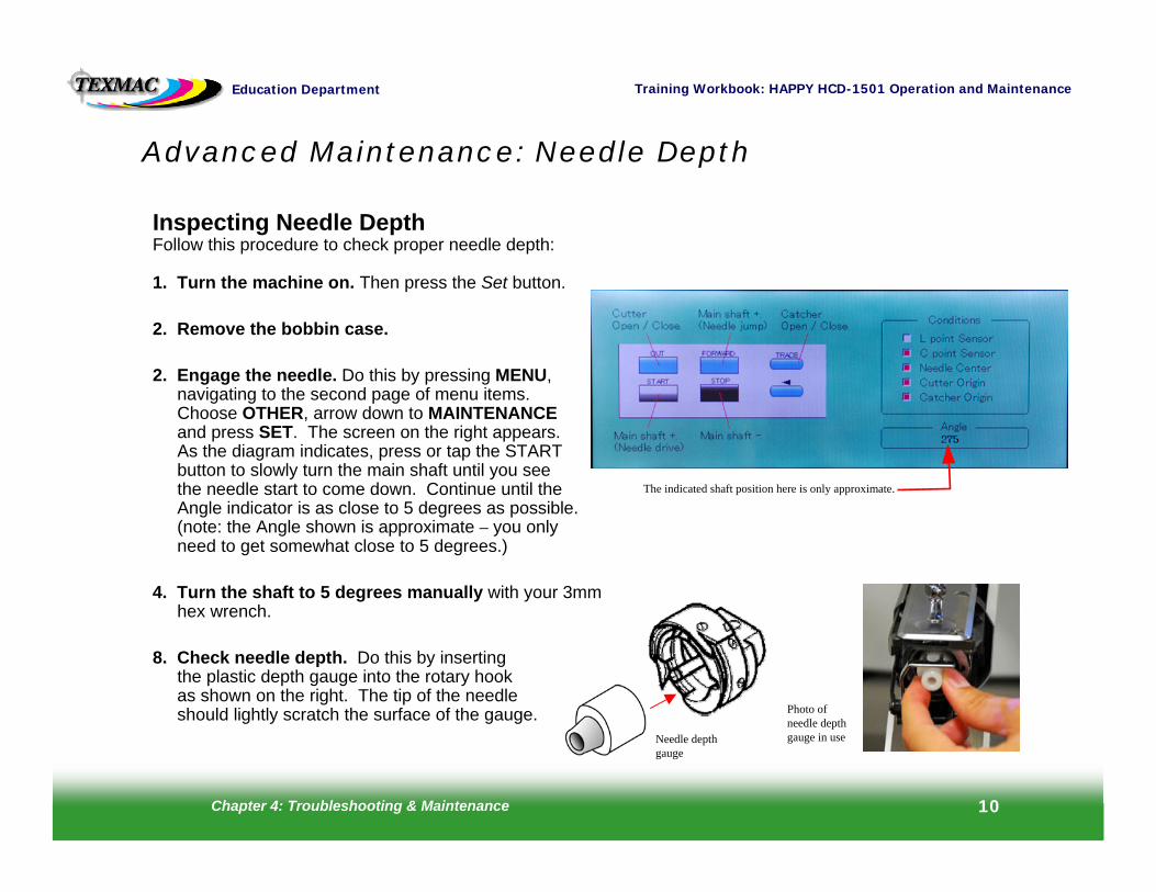
Inspecting Needle DepthFollow this procedure to check proper needle depth:
1. Turn the machine on. Then press the Set button.
2. Remove the bobbin case.
2. Engage the needle. Do this by pressing MENU, navigating to the second page of menu items. Choose OTHER, arrow down to MAINTENANCEand press SET. The screen on the right appears.As the diagram indicates, press or tap the STARTbutton to slowly turn the main shaft until you seethe needle start to come down. Continue until theAngle indicator is as close to 5 degrees as possible. (note: the Angle shown is approximate – you only need to get somewhat close to 5 degrees.)
4. Turn the shaft to 5 degrees manually with your 3mmhex wrench.
8. Check needle depth. Do this by insertingthe plastic depth gauge into the rotary hookas shown on the right. The tip of the needleshould lightly scratch the surface of the gauge.
Advanced Maintenance: Needle Depth
Needle depthgauge
Photo of needle depth gauge in use
The indicated shaft position here is only approximate.
Chapter 4: Troubleshooting & Maintenance 11
Training Workbook: HAPPY HCD-1501 Operation and MaintenanceEducation Department
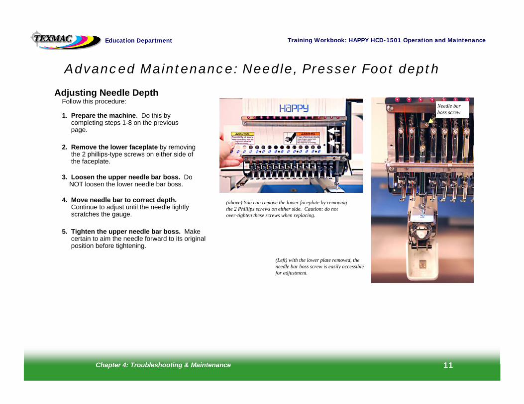
Adjusting Needle DepthFollow this procedure:
1. Prepare the machine. Do this bycompleting steps 1-8 on the previouspage.
2. Remove the lower faceplate by removingthe 2 phillips-type screws on either side ofthe faceplate.
3. Loosen the upper needle bar boss. DoNOT loosen the lower needle bar boss.
4. Move needle bar to correct depth.Continue to adjust until the needle lightlyscratches the gauge.
5. Tighten the upper needle bar boss. Makecertain to aim the needle forward to its originalposition before tightening.
Advanced Maintenance: Needle, Presser Foot depth
(above) You can remove the lower faceplate by removing the 2 Phillips screws on either side. Caution: do not over-tighten these screws when replacing.
(Left) with the lower plate removed, the needle bar boss screw is easily accessible for adjustment.
Needle bar boss screw
Chapter 4: Troubleshooting & Maintenance 12
Training Workbook: HAPPY HCD-1501 Operation and MaintenanceEducation Department
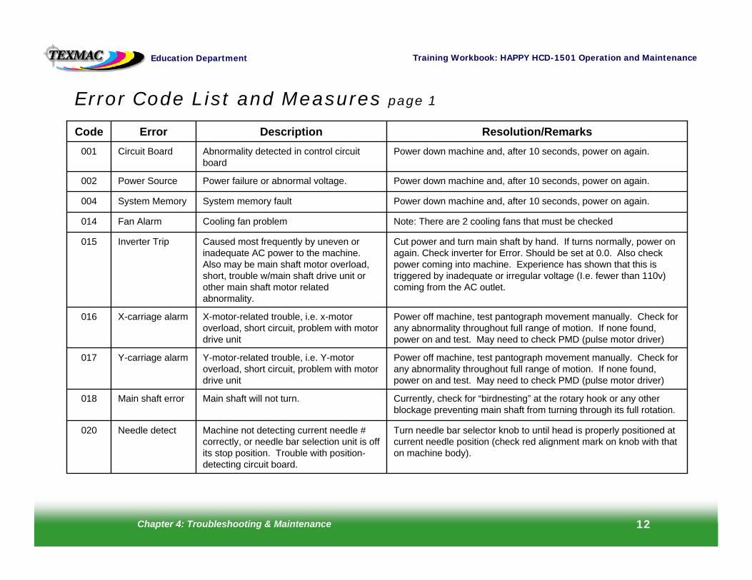
Error Code List and Measures page 1
Note: There are 2 cooling fans that must be checkedCooling fan problemFan Alarm014
Turn needle bar selector knob to until head is properly positioned at current needle position (check red alignment mark on knob with that on machine body).
Machine not detecting current needle # correctly, or needle bar selection unit is off its stop position. Trouble with position-detecting circuit board.
Needle detect020
Currently, check for “birdnesting” at the rotary hook or any other blockage preventing main shaft from turning through its full rotation.
Main shaft will not turn.Main shaft error018
Power off machine, test pantograph movement manually. Check for any abnormality throughout full range of motion. If none found, power on and test. May need to check PMD (pulse motor driver)
Y-motor-related trouble, i.e. Y-motor overload, short circuit, problem with motor drive unit
Y-carriage alarm017
Power off machine, test pantograph movement manually. Check for any abnormality throughout full range of motion. If none found, power on and test. May need to check PMD (pulse motor driver)
X-motor-related trouble, i.e. x-motor overload, short circuit, problem with motor drive unit
X-carriage alarm016
Cut power and turn main shaft by hand. If turns normally, power on again. Check inverter for Error. Should be set at 0.0. Also check power coming into machine. Experience has shown that this is triggered by inadequate or irregular voltage (I.e. fewer than 110v) coming from the AC outlet.
Caused most frequently by uneven or inadequate AC power to the machine. Also may be main shaft motor overload, short, trouble w/main shaft drive unit or other main shaft motor related abnormality.
Inverter Trip015
Power down machine and, after 10 seconds, power on again.System memory faultSystem Memory004
Power down machine and, after 10 seconds, power on again.Power failure or abnormal voltage.Power Source002
Power down machine and, after 10 seconds, power on again.Abnormality detected in control circuit board
Circuit Board001
Resolution/RemarksDescriptionErrorCode
Chapter 4: Troubleshooting & Maintenance 13
Training Workbook: HAPPY HCD-1501 Operation and MaintenanceEducation Department
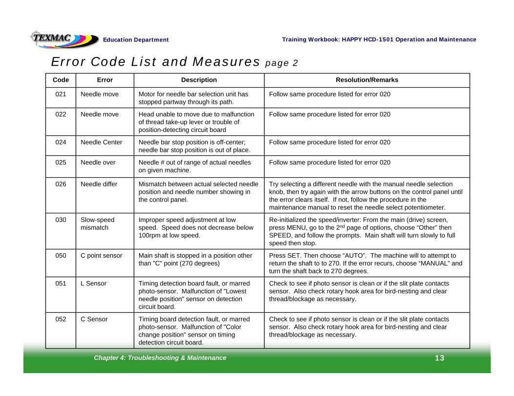
Error Code List and Measures page 2
Check to see if photo sensor is clean or if the slit plate contacts sensor. Also check rotary hook area for bird-nesting and clear thread/blockage as necessary.
Timing detection board fault, or marred photo-sensor. Malfunction of "Lowest needle position" sensor on detection circuit board.
L Sensor051
Check to see if photo sensor is clean or if the slit plate contacts sensor. Also check rotary hook area for bird-nesting and clear thread/blockage as necessary.
Timing board detection fault, or marred photo-sensor. Malfunction of "Color change position" sensor on timing detection circuit board.
C Sensor052
Press SET. Then choose “AUTO”. The machine will to attempt to return the shaft to to 270. If the error recurs, choose “MANUAL” and turn the shaft back to 270 degrees.
Main shaft is stopped in a position other than "C" point (270 degrees)
C point sensor050
Re-initialized the speed/inverter: From the main (drive) screen, press MENU, go to the 2nd page of options, choose “Other” then SPEED, and follow the prompts. Main shaft will turn slowly to full speed then stop.
Improper speed adjustment at low speed. Speed does not decrease below 100rpm at low speed.
Slow-speed mismatch
030
Try selecting a different needle with the manual needle selection knob, then try again with the arrow buttons on the control panel until the error clears itself. If not, follow the procedure in the maintenance manual to reset the needle select potentiometer.
Mismatch between actual selected needle position and needle number showing in the control panel.
Needle differ026
Follow same procedure listed for error 020Needle # out of range of actual needles on given machine.
Needle over025
Follow same procedure listed for error 020Needle bar stop position is off-center; needle bar stop position is out of place.
Needle Center024
Follow same procedure listed for error 020Head unable to move due to malfunction of thread take-up lever or trouble of position-detecting circuit board
Needle move 022
Follow same procedure listed for error 020Motor for needle bar selection unit has stopped partway through its path.
Needle move 021
Resolution/RemarksDescriptionErrorCode
Chapter 4: Troubleshooting & Maintenance 14
Training Workbook: HAPPY HCD-1501 Operation and MaintenanceEducation Department
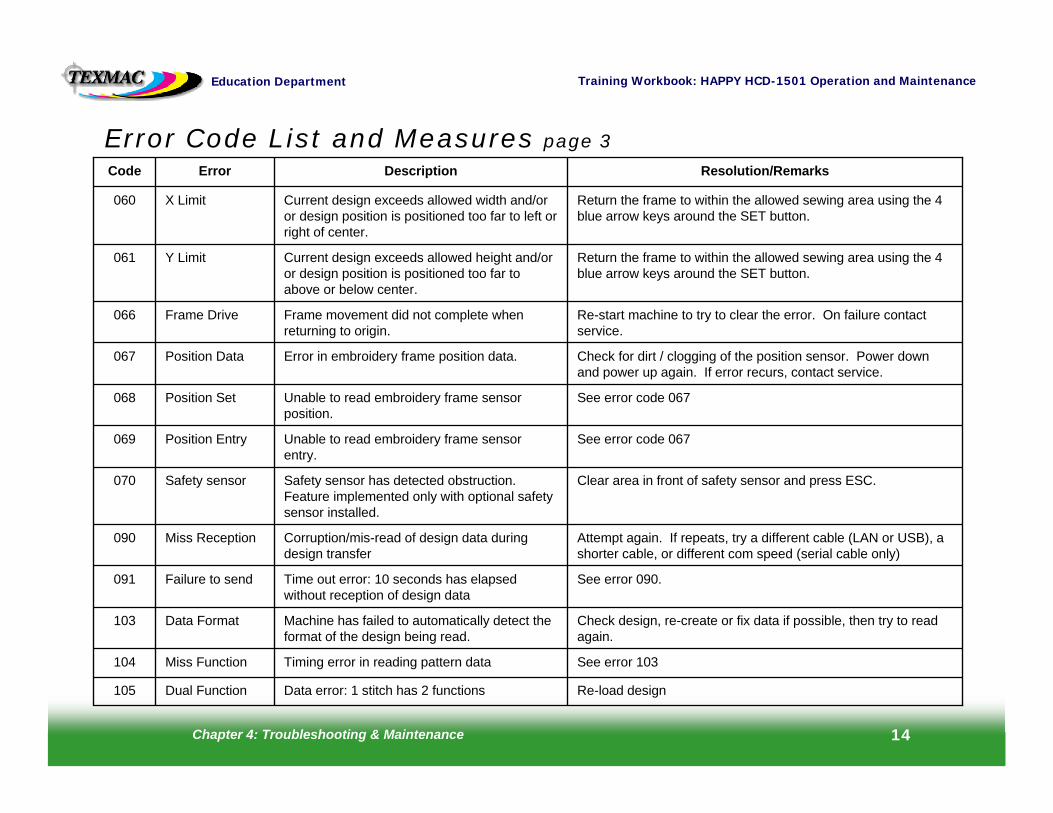
Error Code List and Measures page 3
Check for dirt / clogging of the position sensor. Power down and power up again. If error recurs, contact service.
Error in embroidery frame position data.Position Data067
See error 090.Time out error: 10 seconds has elapsed without reception of design data
Failure to send091
Check design, re-create or fix data if possible, then try to read again.
Machine has failed to automatically detect the format of the design being read.
Data Format103
See error 103Timing error in reading pattern data Miss Function104
Attempt again. If repeats, try a different cable (LAN or USB), a shorter cable, or different com speed (serial cable only)
Corruption/mis-read of design data during design transfer
Miss Reception090
Re-load designData error: 1 stitch has 2 functionsDual Function105
Clear area in front of safety sensor and press ESC. Safety sensor has detected obstruction. Feature implemented only with optional safety sensor installed.
Safety sensor070
See error code 067Unable to read embroidery frame sensor entry.
Position Entry069
See error code 067Unable to read embroidery frame sensor position.
Position Set068
Re-start machine to try to clear the error. On failure contact service.
Frame movement did not complete when returning to origin.
Frame Drive066
Return the frame to within the allowed sewing area using the 4 blue arrow keys around the SET button.
Current design exceeds allowed height and/or or design position is positioned too far to above or below center.
Y Limit061
Return the frame to within the allowed sewing area using the 4 blue arrow keys around the SET button.
Current design exceeds allowed width and/or or design position is positioned too far to left or right of center.
X Limit060
Resolution/RemarksDescriptionErrorCode
Chapter 4: Troubleshooting & Maintenance 15
Training Workbook: HAPPY HCD-1501 Operation and MaintenanceEducation Department
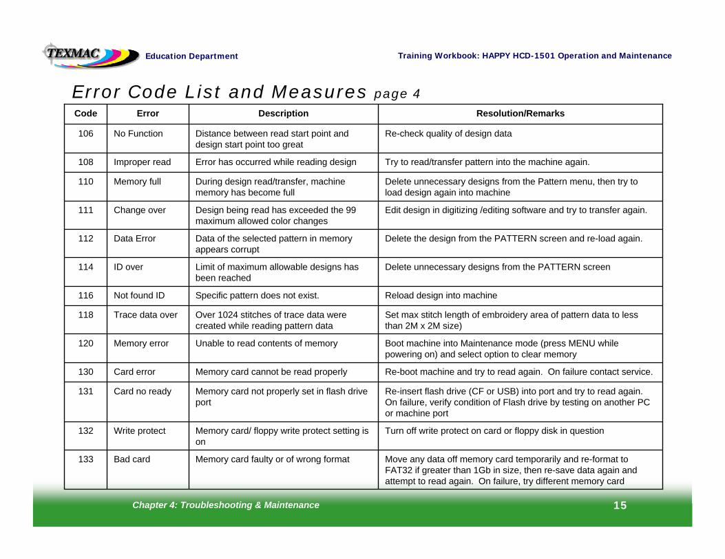
Error Code List and Measures page 4
Move any data off memory card temporarily and re-format to FAT32 if greater than 1Gb in size, then re-save data again and attempt to read again. On failure, try different memory card
Memory card faulty or of wrong formatBad card133
Turn off write protect on card or floppy disk in questionMemory card/ floppy write protect setting is on
Write protect132
Re-insert flash drive (CF or USB) into port and try to read again. On failure, verify condition of Flash drive by testing on another PC or machine port
Memory card not properly set in flash drive port
Card no ready131
Re-boot machine and try to read again. On failure contact service.Memory card cannot be read properlyCard error130
Boot machine into Maintenance mode (press MENU while powering on) and select option to clear memory
Unable to read contents of memoryMemory error120
Set max stitch length of embroidery area of pattern data to lessthan 2M x 2M size)
Over 1024 stitches of trace data were created while reading pattern data
Trace data over118
Reload design into machineSpecific pattern does not exist.Not found ID116
Delete unnecessary designs from the PATTERN screenLimit of maximum allowable designs has been reached
ID over114
Delete the design from the PATTERN screen and re-load again.Data of the selected pattern in memory appears corrupt
Data Error112
Edit design in digitizing /editing software and try to transfer again.Design being read has exceeded the 99 maximum allowed color changes
Change over111
Delete unnecessary designs from the Pattern menu, then try to load design again into machine
During design read/transfer, machine memory has become full
Memory full110
Try to read/transfer pattern into the machine again.Error has occurred while reading designImproper read108
Re-check quality of design dataDistance between read start point and design start point too great
No Function106
Resolution/RemarksDescriptionErrorCode
Chapter 4: Troubleshooting & Maintenance 16
Training Workbook: HAPPY HCD-1501 Operation and MaintenanceEducation Department
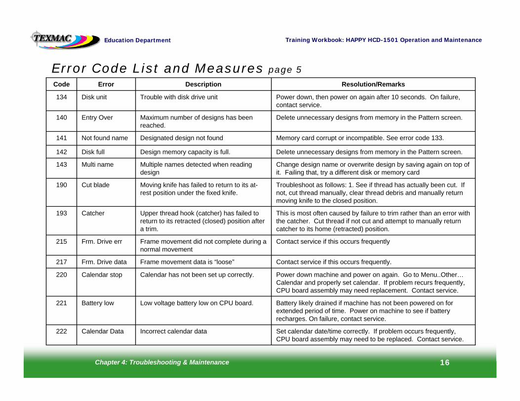
Error Code List and Measures page 5
Set calendar date/time correctly. If problem occurs frequently,CPU board assembly may need to be replaced. Contact service.
Incorrect calendar dataCalendar Data222
Battery likely drained if machine has not been powered on for extended period of time. Power on machine to see if battery recharges. On failure, contact service.
Low voltage battery low on CPU board.Battery low221
Power down machine and power on again. Go to Menu..Other…Calendar and properly set calendar. If problem recurs frequently, CPU board assembly may need replacement. Contact service.
Calendar has not been set up correctly.Calendar stop220
Contact service if this occurs frequently.Frame movement data is “loose”Frm. Drive data 217
Contact service if this occurs frequentlyFrame movement did not complete during a normal movement
Frm. Drive err215
This is most often caused by failure to trim rather than an error with the catcher. Cut thread if not cut and attempt to manually return catcher to its home (retracted) position.
Upper thread hook (catcher) has failed to return to its retracted (closed) position after a trim.
Catcher193
Troubleshoot as follows: 1. See if thread has actually been cut. If not, cut thread manually, clear thread debris and manually return moving knife to the closed position.
Moving knife has failed to return to its at-rest position under the fixed knife.
Cut blade190
Change design name or overwrite design by saving again on top ofit. Failing that, try a different disk or memory card
Multiple names detected when reading design
Multi name143
Delete unnecessary designs from memory in the Pattern screen.Design memory capacity is full.Disk full142
Memory card corrupt or incompatible. See error code 133.Designated design not foundNot found name141
Delete unnecessary designs from memory in the Pattern screen.Maximum number of designs has been reached.
Entry Over140
Power down, then power on again after 10 seconds. On failure, contact service.
Trouble with disk drive unitDisk unit134
Resolution/RemarksDescriptionErrorCode