Embed Size (px)
Citation preview
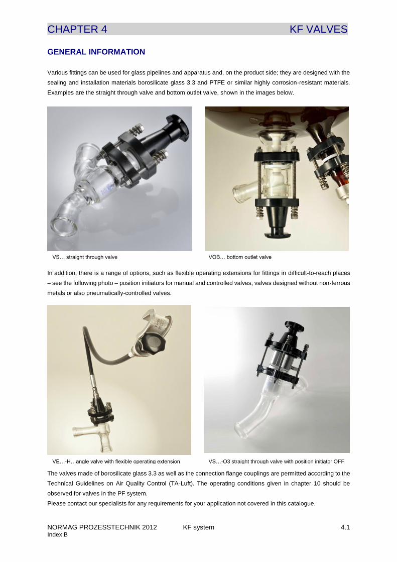
CHAPTER 4 KF VALVES
NORMAG PROZESSTECHNIK 2012 KF system 4.1 Index B
GENERAL INFORMATION
Various fittings can be used for glass pipelines and apparatus and, on the product side; they are designed with the
sealing and installation materials borosilicate glass 3.3 and PTFE or similar highly corrosion-resistant materials.
Examples are the straight through valve and bottom outlet valve, shown in the images below.
In addition, there is a range of options, such as flexible operating extensions for fittings in difficult-to-reach places
– see the following photo – position initiators for manual and controlled valves, valves designed without non-ferrous
metals or also pneumatically-controlled valves.
The valves made of borosilicate glass 3.3 as well as the connection flange couplings are permitted according to the
Technical Guidelines on Air Quality Control (TA-Luft). The operating conditions given in chapter 10 should be
observed for valves in the PF system.
Please contact our specialists for any requirements for your application not covered in this catalogue.
VE…-H…angle valve with flexible operating extension VS…-O3 straight through valve with position initiator OFF
VS… straight through valve VOB… bottom outlet valve
CHAPTER 4 KF VALVES
NORMAG PROZESSTECHNIK 2012 KF system 4.2 Index B
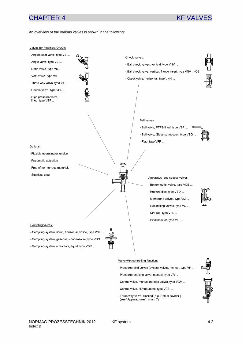
An overview of the various valves is shown in the following:

CHAPTER 4 KF VALVES
NORMAG PROZESSTECHNIK 2012 KF system 4.3 Index B
VALVES, ON/OFF
Valves are designed highly corrosion-resistant with a valve housing made of borosilicate glass 3.3 and a valve
plunger made of PTFE. The valve plunger is designed in the form of bellows and is operated using a spindle without
a packing gland. Aside from opening / closing, the flow rate can be controlled and set using the head of the valve
plunger.
The ON/OFF valves are available as straight through valves and angle valves. The options given at the end of this
chapter can be selected for the valves. Examples are:
Description of OPTIONAL MANUAL ON/OFF VALVES: Item number Example
Straight through valve, KF system: VS….-K VS 025-K
Angle valve, KF system: VE….-K VE 025-K
Angle valve, KF system, former design: VE….-K-O10 VE 025-K-O10
Angle valve, KF system, with a TAG number provided by the customer: VE….-K-TAG VE 025-K-TAG
Straight through valve, KF system, flexible operating extension 1 m: VS….-K-H22 VS 025-K-H22
Straight through valve, KF system, manual, positioning feedback OFF: VS….-K-O3 VS 025-K-O3
Straight through valve, KF system, conductive PTFE with earthing: VS….-K-M2 VS 025-K-M2
Straight through valve, KF system, with PTFE round bellow folds: VS….-K-M3 VS 025-K-M3
Straight through valve, KF system, conductive coating and PTFE: VS….-K-C3-M2 VS 025-K-C3-M2
Straight through valve, KF system, with FDA material certificates: VE….-K-Z1 VE 025-K-Z1
By entering the option “SP…” replacement parts can also be ordered for the valves.
Description of SPARE PARTS FOR MANUAL ON/OFF VALVES: Item number Example
Glass valve body for angle valve, KF system: VS….-K-SP01 VS 025-K-SP01
PTFE plug for on/off valves, PF and KF system: VS….-SP02 VS 025-SP02
PTFE plug for on/off valves, KF system, former design: VS….-K-O10-SP02 VS025-K-O10-SP02
Valve top, manual, PF and KF system: VS….-SP03 VS 025-SP03
Valve top together with PTFE plug, PF and KF system: VS….-SP04 VS 025-SP04
The on/off valves can optionally be designed with a pneumatic actuator manufactured by SAMSON. In order to
mount the pneumatic valves each of the yoke rods is fitted with a ¾“-connection structure fitting. The valve air
pressure only measures 2.5 bar for actuators and this value is not allowed to be exceeded by more than 10 %. An
air supply pressure controller can additionally be attached on request.
The – RP … options given at the end of this chapter can be selected for the pneumatic valves with the following
basic definitions.
- Explosion-proof design (ATEX)
- Safety position OPEN/CLOSED
- Position indicator for valve position OPEN/CLOSED
- Design with/without solenoid valve
Examples of item descriptions corresponding to pneumatic valves are:
Description of extra PNEUMATIC OPTIONS: Item number Example
Angle valve, KF system, pneumatic, not EX proof, safety position VE….-K-RP0100 VE 025-K-RP0100
CLOSED, without position indicator, without solenoid valve
Angle valve, KF system, pneumatic, EX proof, safety position OPEN VE….-K-RP1231 VE 025-K-RP1231
with position indicator, with solenoid valve
CHAPTER 4 KF VALVES
NORMAG PROZESSTECHNIK 2012 KF system 4.4 Index B
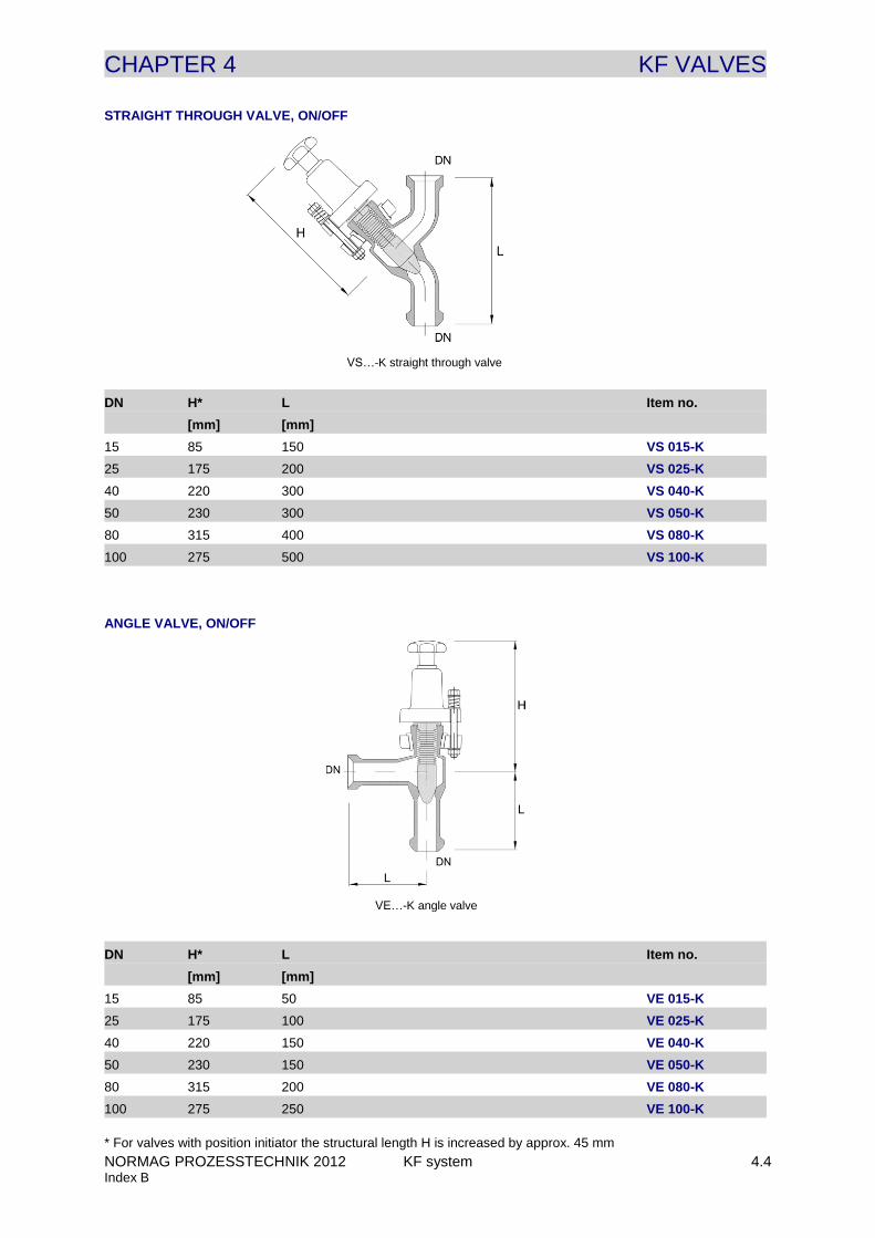
STRAIGHT THROUGH VALVE, ON/OFF
DN H* L Item no.
[mm] [mm]
15 85 150 VS 015-K
25 175 200 VS 025-K
40 220 300 VS 040-K
50 230 300 VS 050-K
80 315 400 VS 080-K
100 275 500 VS 100-K
ANGLE VALVE, ON/OFF
DN H* L Item no.
[mm] [mm]
15 85 50 VE 015-K
25 175 100 VE 025-K
40 220 150 VE 040-K
50 230 150 VE 050-K
80 315 200 VE 080-K
100 275 250 VE 100-K
* For valves with position initiator the structural length H is increased by approx. 45 mm
VS…-K straight through valve
VE…-K angle valve
CHAPTER 4 KF VALVES
NORMAG PROZESSTECHNIK 2012 KF system 4.5 Index B
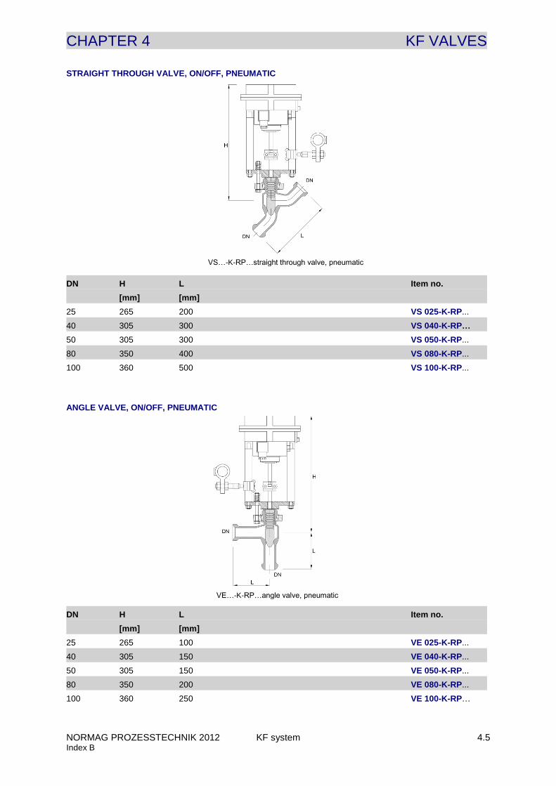
STRAIGHT THROUGH VALVE, ON/OFF, PNEUMATIC
DN H L Item no.
[mm] [mm]
25 265 200 VS 025-K-RP...
40 305 300 VS 040-K-RP...
50 305 300 VS 050-K-RP...
80 350 400 VS 080-K-RP...
100 360 500 VS 100-K-RP...
ANGLE VALVE, ON/OFF, PNEUMATIC
DN H L Item no.
[mm] [mm]
25 265 100 VE 025-K-RP...
40 305 150 VE 040-K-RP...
50 305 150 VE 050-K-RP...
80 350 200 VE 080-K-RP...
100 360 250 VE 100-K-RP…
VS…-K-RP…straight through valve, pneumatic
VE…-K-RP…angle valve, pneumatic
CHAPTER 4 KF VALVES
NORMAG PROZESSTECHNIK 2012 KF system 4.6 Index B
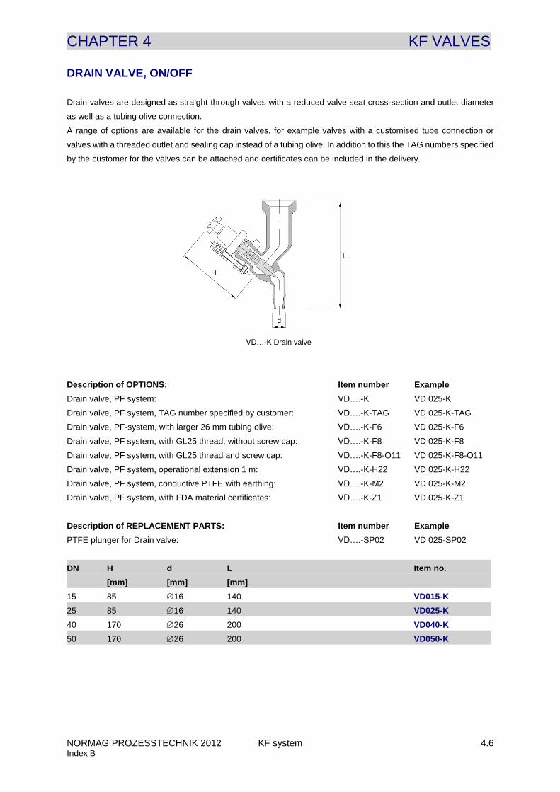
DRAIN VALVE, ON/OFF
Drain valves are designed as straight through valves with a reduced valve seat cross-section and outlet diameter
as well as a tubing olive connection.
A range of options are available for the drain valves, for example valves with a customised tube connection or
valves with a threaded outlet and sealing cap instead of a tubing olive. In addition to this the TAG numbers specified
by the customer for the valves can be attached and certificates can be included in the delivery.
Description of OPTIONS: Item number Example
Drain valve, PF system: VD….-K VD 025-K
Drain valve, PF system, TAG number specified by customer: VD….-K-TAG VD 025-K-TAG
Drain valve, PF-system, with larger 26 mm tubing olive: VD….-K-F6 VD 025-K-F6
Drain valve, PF system, with GL25 thread, without screw cap: VD….-K-F8 VD 025-K-F8
Drain valve, PF system, with GL25 thread and screw cap: VD….-K-F8-O11 VD 025-K-F8-O11
Drain valve, PF system, operational extension 1 m: VD….-K-H22 VD 025-K-H22
Drain valve, PF system, conductive PTFE with earthing: VD….-K-M2 VD 025-K-M2
Drain valve, PF system, with FDA material certificates: VD….-K-Z1 VD 025-K-Z1
Description of REPLACEMENT PARTS: Item number Example
PTFE plunger for Drain valve: VD….-SP02 VD 025-SP02
DN H d L Item no.
[mm] [mm] [mm]
15 85 16 140 VD015-K
25 85 16 140 VD025-K
40 170 26 200 VD040-K
50 170 26 200 VD050-K
VD…-K Drain valve
CHAPTER 4 KF VALVES
NORMAG PROZESSTECHNIK 2012 KF system 4.7 Index B
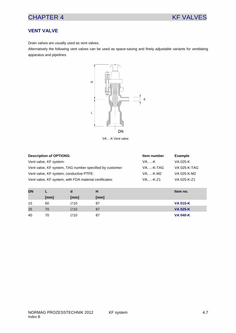
VENT VALVE
Drain valves are usually used as vent valves.
Alternatively the following vent valves can be used as space-saving and finely adjustable variants for ventilating
apparatus and pipelines.
Description of OPTIONS: Item number Example
Vent valve, KF system: VA….-K VA 025-K
Vent valve, KF system, TAG number specified by customer: VA….-K-TAG VA 025-K-TAG
Vent valve, KF system, conductive PTFE: VA….-K-M2 VA 025-K-M2
Vent valve, KF system, with FDA material certificates: VA….-K-Z1 VA 025-K-Z1
DN L d H Item no.
[mm] [mm] [mm]
15 60 10 87 VA 015-K
25 70 10 87 VA 025-K
40 70 10 87 VA 040-K
VA…-K Vent valve

CHAPTER 4 KF VALVES
NORMAG PROZESSTECHNIK 2012 KF system 4.8 Index B
THREE WAY VALVE
Three way valves are designed with a double valve seat so that one passage is always open. Therefore three way
valves are always used in situations when it needs to be ensured that both outlets are not shut at the same time,
which would lead to unpermitted high pressures building up in the supply pipe.
Description of OPTIONS: Item number Example
Three way valve, KF system: VT….-K VT 025-K
Three way valve, KF system, TAG-number specified by customer: VT….-K-TAG VT 025-K-TAG
Three way valve, KF system, conductive PTFE: VT….-K-M2 VT 025-K-M2
Three way valve, KF system, with FDA material certificates: VT….-K-Z1 VT 025-K-Z1
DN L L1 H Item no.
[mm] [mm] [mm]
25 100 160 232 VT 025-K
40 150 220 270 VT 040-K
VT…-K three way valve
CHAPTER 4 KF VALVES
NORMAG PROZESSTECHNIK 2012 KF system 4.9 Index B
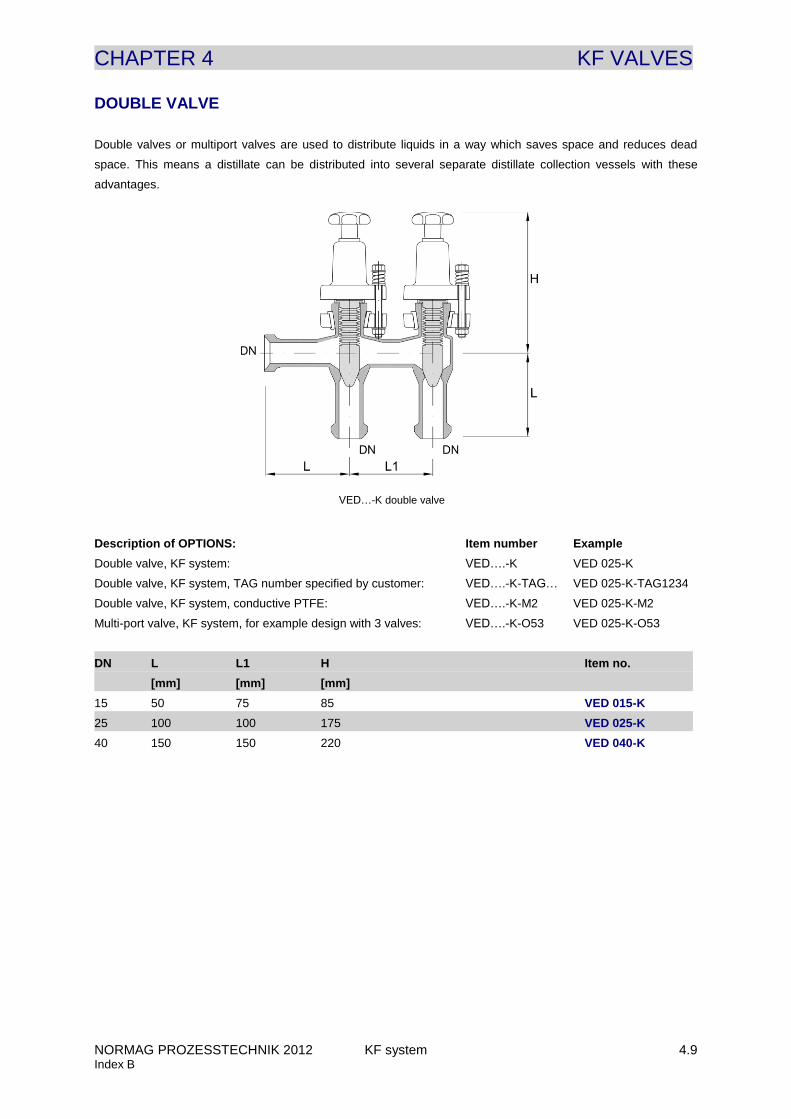
DOUBLE VALVE
Double valves or multiport valves are used to distribute liquids in a way which saves space and reduces dead
space. This means a distillate can be distributed into several separate distillate collection vessels with these
advantages.
Description of OPTIONS: Item number Example
Double valve, KF system: VED….-K VED 025-K
Double valve, KF system, TAG number specified by customer: VED….-K-TAG… VED 025-K-TAG1234
Double valve, KF system, conductive PTFE: VED….-K-M2 VED 025-K-M2
Multi-port valve, KF system, for example design with 3 valves: VED….-K-O53 VED 025-K-O53
DN L L1 H Item no.
[mm] [mm] [mm]
15 50 75 85 VED 015-K
25 100 100 175 VED 025-K
40 150 150 220 VED 040-K
VED…-K double valve
CHAPTER 4 KF VALVES
NORMAG PROZESSTECHNIK 2012 KF system 4.10 Index B
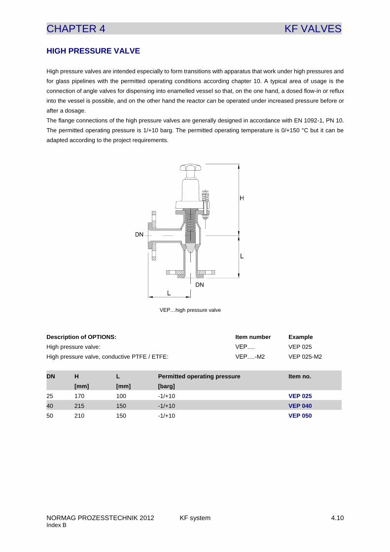
HIGH PRESSURE VALVE
High pressure valves are intended especially to form transitions with apparatus that work under high pressures and
for glass pipelines with the permitted operating conditions according chapter 10. A typical area of usage is the
connection of angle valves for dispensing into enamelled vessel so that, on the one hand, a dosed flow-in or reflux
into the vessel is possible, and on the other hand the reactor can be operated under increased pressure before or
after a dosage.
The flange connections of the high pressure valves are generally designed in accordance with EN 1092-1, PN 10.
The permitted operating pressure is 1/+10 barg. The permitted operating temperature is 0/+150 °C but it can be
adapted according to the project requirements.
Description of OPTIONS: Item number Example
High pressure valve: VEP…. VEP 025
High pressure valve, conductive PTFE / ETFE: VEP….-M2 VEP 025-M2
DN H L Permitted operating pressure Item no.
[mm] [mm] [barg]
25 170 100 -1/+10 VEP 025
40 215 150 -1/+10 VEP 040
50 210 150 -1/+10 VEP 050
VEP…high pressure valve
CHAPTER 4 KF VALVES
NORMAG PROZESSTECHNIK 2012 KF system 4.11 Index B
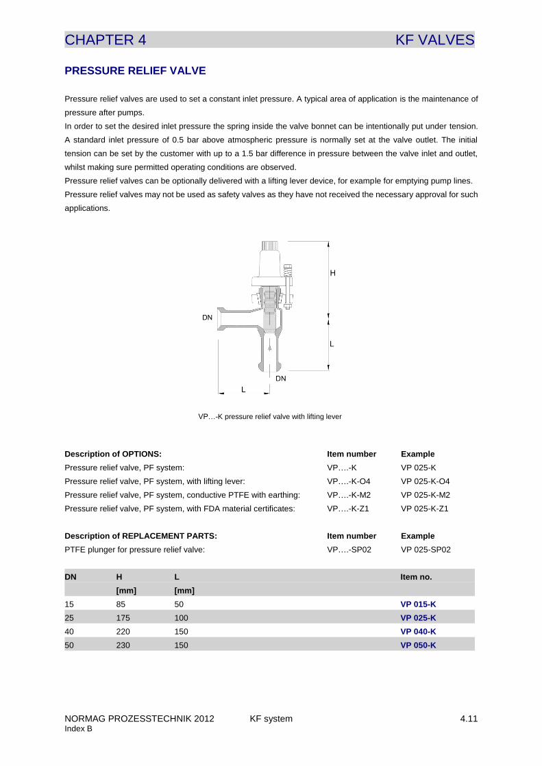
PRESSURE RELIEF VALVE
Pressure relief valves are used to set a constant inlet pressure. A typical area of application is the maintenance of
pressure after pumps.
In order to set the desired inlet pressure the spring inside the valve bonnet can be intentionally put under tension.
A standard inlet pressure of 0.5 bar above atmospheric pressure is normally set at the valve outlet. The initial
tension can be set by the customer with up to a 1.5 bar difference in pressure between the valve inlet and outlet,
whilst making sure permitted operating conditions are observed.
Pressure relief valves can be optionally delivered with a lifting lever device, for example for emptying pump lines.
Pressure relief valves may not be used as safety valves as they have not received the necessary approval for such
applications.
Description of OPTIONS: Item number Example
Pressure relief valve, PF system: VP….-K VP 025-K
Pressure relief valve, PF system, with lifting lever: VP….-K-O4 VP 025-K-O4
Pressure relief valve, PF system, conductive PTFE with earthing: VP….-K-M2 VP 025-K-M2
Pressure relief valve, PF system, with FDA material certificates: VP….-K-Z1 VP 025-K-Z1
Description of REPLACEMENT PARTS: Item number Example
PTFE plunger for pressure relief valve: VP….-SP02 VP 025-SP02
DN H L Item no.
[mm] [mm]
15 85 50 VP 015-K
25 175 100 VP 025-K
40 220 150 VP 040-K
50 230 150 VP 050-K
VP…-K pressure relief valve with lifting lever
CHAPTER 4 KF VALVES
NORMAG PROZESSTECHNIK 2012 KF system 4.12 Index B
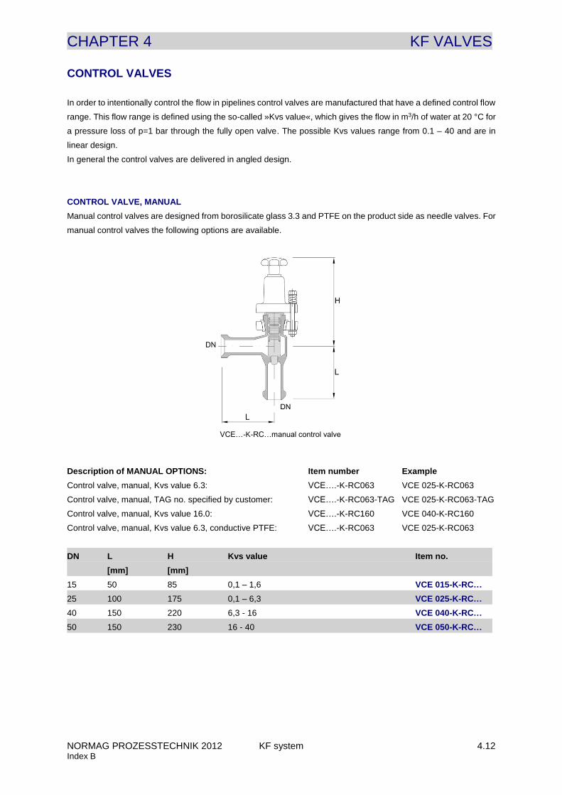
CONTROL VALVES
FITTINGS
In order to intentionally control the flow in pipelines control valves are manufactured that have a defined control flow
range. This flow range is defined using the so-called »Kvs value«, which gives the flow in m3/h of water at 20 °C for
a pressure loss of p=1 bar through the fully open valve. The possible Kvs values range from 0.1 – 40 and are in
linear design.
In general the control valves are delivered in angled design.
CONTROL VALVE, MANUAL
Manual control valves are designed from borosilicate glass 3.3 and PTFE on the product side as needle valves. For
manual control valves the following options are available.
Description of MANUAL OPTIONS: Item number Example
Control valve, manual, Kvs value 6.3: VCE….-K-RC063 VCE 025-K-RC063
Control valve, manual, TAG no. specified by customer: VCE….-K-RC063-TAG VCE 025-K-RC063-TAG
Control valve, manual, Kvs value 16.0: VCE….-K-RC160 VCE 040-K-RC160
Control valve, manual, Kvs value 6.3, conductive PTFE: VCE….-K-RC063 VCE 025-K-RC063
DN L H Kvs value Item no.
[mm] [mm]
15 50 85 0,1 – 1,6 VCE 015-K-RC…
25 100 175 0,1 – 6,3 VCE 025-K-RC…
40 150 220 6,3 - 16 VCE 040-K-RC…
50 150 230 16 - 40 VCE 050-K-RC…
VCE…-K-RC…manual control valve
CHAPTER 4 KF VALVES
NORMAG PROZESSTECHNIK 2012 KF system 4.13 Index B
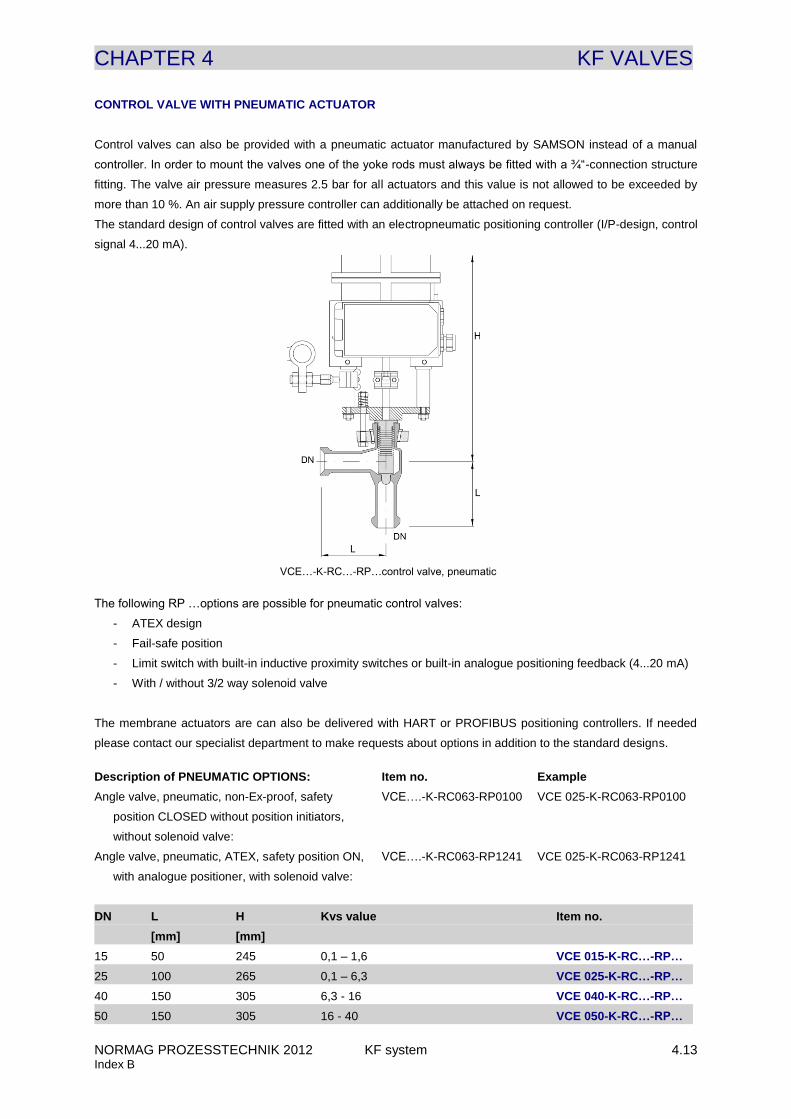
CONTROL VALVE WITH PNEUMATIC ACTUATOR
Control valves can also be provided with a pneumatic actuator manufactured by SAMSON instead of a manual
controller. In order to mount the valves one of the yoke rods must always be fitted with a ¾“-connection structure
fitting. The valve air pressure measures 2.5 bar for all actuators and this value is not allowed to be exceeded by
more than 10 %. An air supply pressure controller can additionally be attached on request.
The standard design of control valves are fitted with an electropneumatic positioning controller (I/P-design, control
signal 4...20 mA).
The following RP …options are possible for pneumatic control valves:
- ATEX design
- Fail-safe position
- Limit switch with built-in inductive proximity switches or built-in analogue positioning feedback (4...20 mA)
- With / without 3/2 way solenoid valve
The membrane actuators are can also be delivered with HART or PROFIBUS positioning controllers. If needed
please contact our specialist department to make requests about options in addition to the standard designs.
Description of PNEUMATIC OPTIONS: Item no. Example
Angle valve, pneumatic, non-Ex-proof, safety VCE….-K-RC063-RP0100 VCE 025-K-RC063-RP0100
position CLOSED without position initiators,
without solenoid valve:
Angle valve, pneumatic, ATEX, safety position ON, VCE….-K-RC063-RP1241 VCE 025-K-RC063-RP1241
with analogue positioner, with solenoid valve:
DN L H Kvs value Item no.
[mm] [mm]
15 50 245 0,1 – 1,6 VCE 015-K-RC…-RP…
25 100 265 0,1 – 6,3 VCE 025-K-RC…-RP…
40 150 305 6,3 - 16 VCE 040-K-RC…-RP…
50 150 305 16 - 40 VCE 050-K-RC…-RP…
VCE…-K-RC…-RP…control valve, pneumatic
CHAPTER 4 KF VALVES
NORMAG PROZESSTECHNIK 2012 KF system 4.14 Index B
SAMPLING VALVES
Sampling valves are needed in the construction of glass apparatus for apparatus and for pipelines. The samples
are mainly taken as liquids but sometimes also as condensable vapours. The corresponding standard solutions are
described in the following.
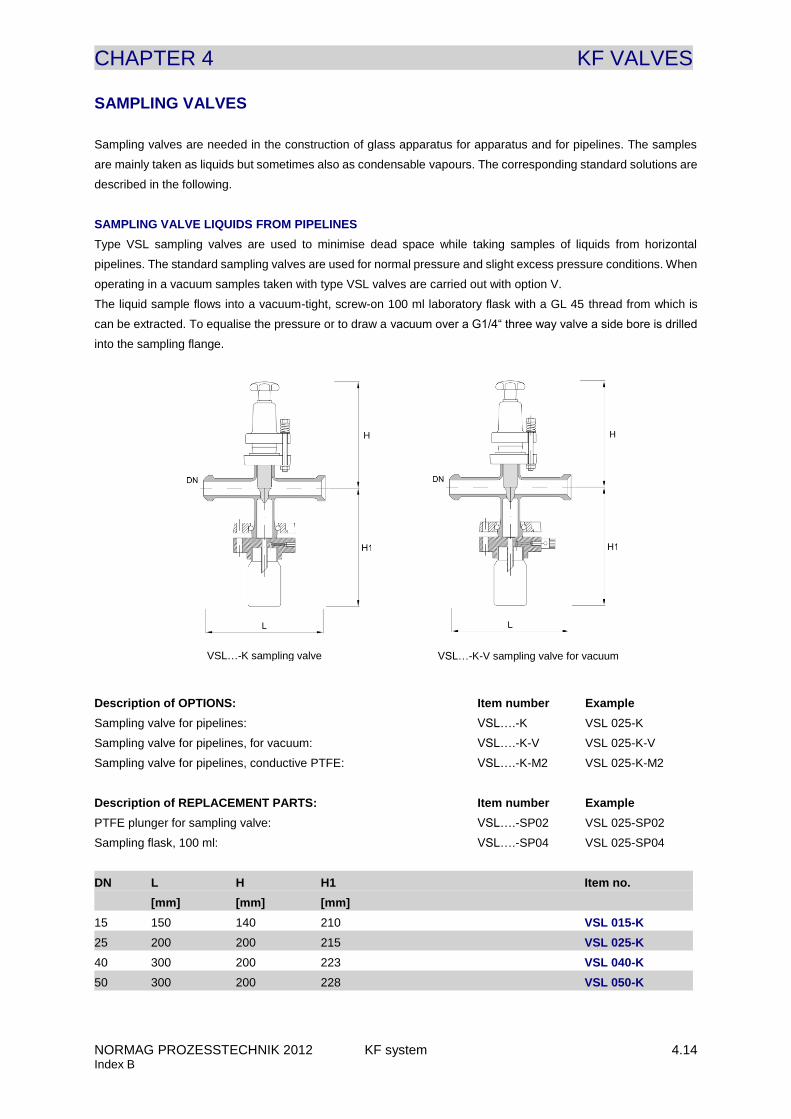
SAMPLING VALVE LIQUIDS FROM PIPELINES
Type VSL sampling valves are used to minimise dead space while taking samples of liquids from horizontal
pipelines. The standard sampling valves are used for normal pressure and slight excess pressure conditions. When
operating in a vacuum samples taken with type VSL valves are carried out with option V.
The liquid sample flows into a vacuum-tight, screw-on 100 ml laboratory flask with a GL 45 thread from which is
can be extracted. To equalise the pressure or to draw a vacuum over a G1/4“ three way valve a side bore is drilled
into the sampling flange.
Description of OPTIONS: Item number Example
Sampling valve for pipelines: VSL….-K VSL 025-K
Sampling valve for pipelines, for vacuum: VSL….-K-V VSL 025-K-V
Sampling valve for pipelines, conductive PTFE: VSL….-K-M2 VSL 025-K-M2
Description of REPLACEMENT PARTS: Item number Example
PTFE plunger for sampling valve: VSL….-SP02 VSL 025-SP02
Sampling flask, 100 ml: VSL….-SP04 VSL 025-SP04
DN L H H1 Item no.
[mm] [mm] [mm]
15 150 140 210 VSL 015-K
25 200 200 215 VSL 025-K
40 300 200 223 VSL 040-K
50 300 200 228 VSL 050-K
VSL…-K sampling valve VSL…-K-V sampling valve for vacuum
CHAPTER 4 KF VALVES
NORMAG PROZESSTECHNIK 2012 KF system 4.15 Index B
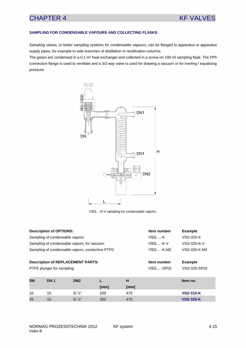
SAMPLING FOR CONDENSABLE VAPOURS AND COLLECTING FLASKS
Sampling valves, or better sampling systems for condensable vapours, can be flanged to apparatus or apparatus
supply pipes, for example to side branches of distillation or rectification columns.
The gases are condensed in a 0.1 m² heat exchanger and collected in a screw-on 100 ml sampling flask. The PPh
connection flange is used to ventilate and a 3/2 way valve is used for drawing a vacuum or for inerting / equalising
pressure.
Description of OPTIONS: Item number Example
Sampling of condensable vapors: VSG….-K VSG 025-K
Sampling of condensable vapors, for vacuum: VSG….-K-V VSG 025-K-V
Sampling of condensable vapors, conductive PTFE: VSG….-K-M2 VSG 025-K-M2
Description of REPLACEMENT PARTS: Item number Example
PTFE plunger for sampling: VSG….-SP02 VSG 025-SP02
DN DN 1 DN2 L H Item no.
[mm] [mm]
15 15 G ¼“ 200 475 VSG 015-K
25 15 G ¼“ 200 475 VSG 025-K
VSG…-K-V sampling for condensable vapors,
CHAPTER 4 KF VALVES
NORMAG PROZESSTECHNIK 2012 KF system 4.16 Index B
CHECK VALVES
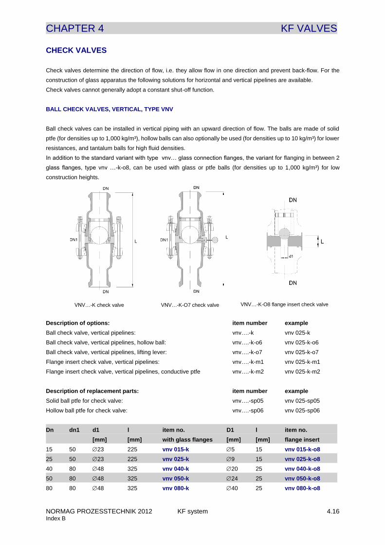
Check valves determine the direction of flow, i.e. they allow flow in one direction and prevent back-flow. For the
construction of glass apparatus the following solutions for horizontal and vertical pipelines are available.
Check valves cannot generally adopt a constant shut-off function.
BALL CHECK VALVES, VERTICAL, TYPE VNV
Ball check valves can be installed in vertical piping with an upward direction of flow. The balls are made of solid
ptfe (for densities up to 1,000 kg/m³), hollow balls can also optionally be used (for densities up to 10 kg/m³) for lower
resistances, and tantalum balls for high fluid densities.
In addition to the standard variant with type vnv… glass connection flanges, the variant for flanging in between 2
glass flanges, type vnv …-k-o8, can be used with glass or ptfe balls (for densities up to 1,000 kg/m³) for low
construction heights.
Description of options: item number example
Ball check valve, vertical pipelines: vnv….-k vnv 025-k
Ball check valve, vertical pipelines, hollow ball: vnv….-k-o6 vnv 025-k-o6
Ball check valve, vertical pipelines, lifting lever: vnv….-k-o7 vnv 025-k-o7
Flange insert check valve, vertical pipelines: vnv….-k-m1 vnv 025-k-m1
Flange insert check valve, vertical pipelines, conductive ptfe vnv….-k-m2 vnv 025-k-m2
Description of replacement parts: item number example
Solid ball ptfe for check valve: vnv….-sp05 vnv 025-sp05
Hollow ball ptfe for check valve: vnv….-sp06 vnv 025-sp06
Dn dn1 d1 l item no. D1 l item no.
[mm] [mm] with glass flanges [mm] [mm] flange insert
15 50 23 225 vnv 015-k 5 15 vnv 015-k-o8
25 50 23 225 vnv 025-k 9 15 vnv 025-k-o8
40 80 48 325 vnv 040-k 20 25 vnv 040-k-o8
50 80 48 325 vnv 050-k 24 25 vnv 050-k-o8
80 80 48 325 vnv 080-k 40 25 vnv 080-k-o8
VNV…-K-O8 flange insert check valve VNV…-K check valve VNV…-K-O7 check valve
CHAPTER 4 KF VALVES
NORMAG PROZESSTECHNIK 2012 KF system 4.17 Index B
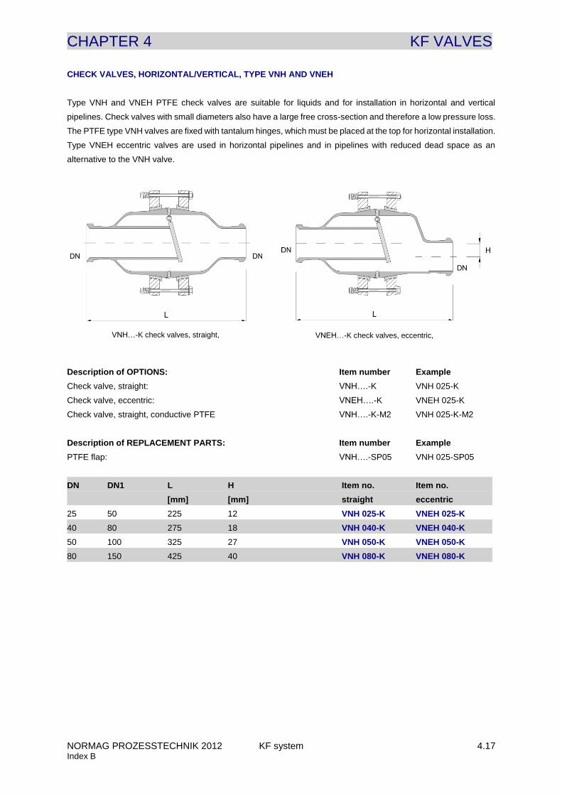
CHECK VALVES, HORIZONTAL/VERTICAL, TYPE VNH AND VNEH
Type VNH and VNEH PTFE check valves are suitable for liquids and for installation in horizontal and vertical
pipelines. Check valves with small diameters also have a large free cross-section and therefore a low pressure loss.
The PTFE type VNH valves are fixed with tantalum hinges, which must be placed at the top for horizontal installation.
Type VNEH eccentric valves are used in horizontal pipelines and in pipelines with reduced dead space as an
alternative to the VNH valve.
Description of OPTIONS: Item number Example
Check valve, straight: VNH….-K VNH 025-K
Check valve, eccentric: VNEH….-K VNEH 025-K
Check valve, straight, conductive PTFE VNH….-K-M2 VNH 025-K-M2
Description of REPLACEMENT PARTS: Item number Example
PTFE flap: VNH….-SP05 VNH 025-SP05
DN DN1 L H Item no. Item no.
[mm] [mm] straight eccentric
25 50 225 12 VNH 025-K VNEH 025-K
40 80 275 18 VNH 040-K VNEH 040-K
50 100 325 27 VNH 050-K VNEH 050-K
80 150 425 40 VNH 080-K VNEH 080-K
VNH…-K check valves, straight, VNEH…-K check valves, eccentric,
CHAPTER 4 KF VALVES
NORMAG PROZESSTECHNIK 2012 KF system 4.18 Index B
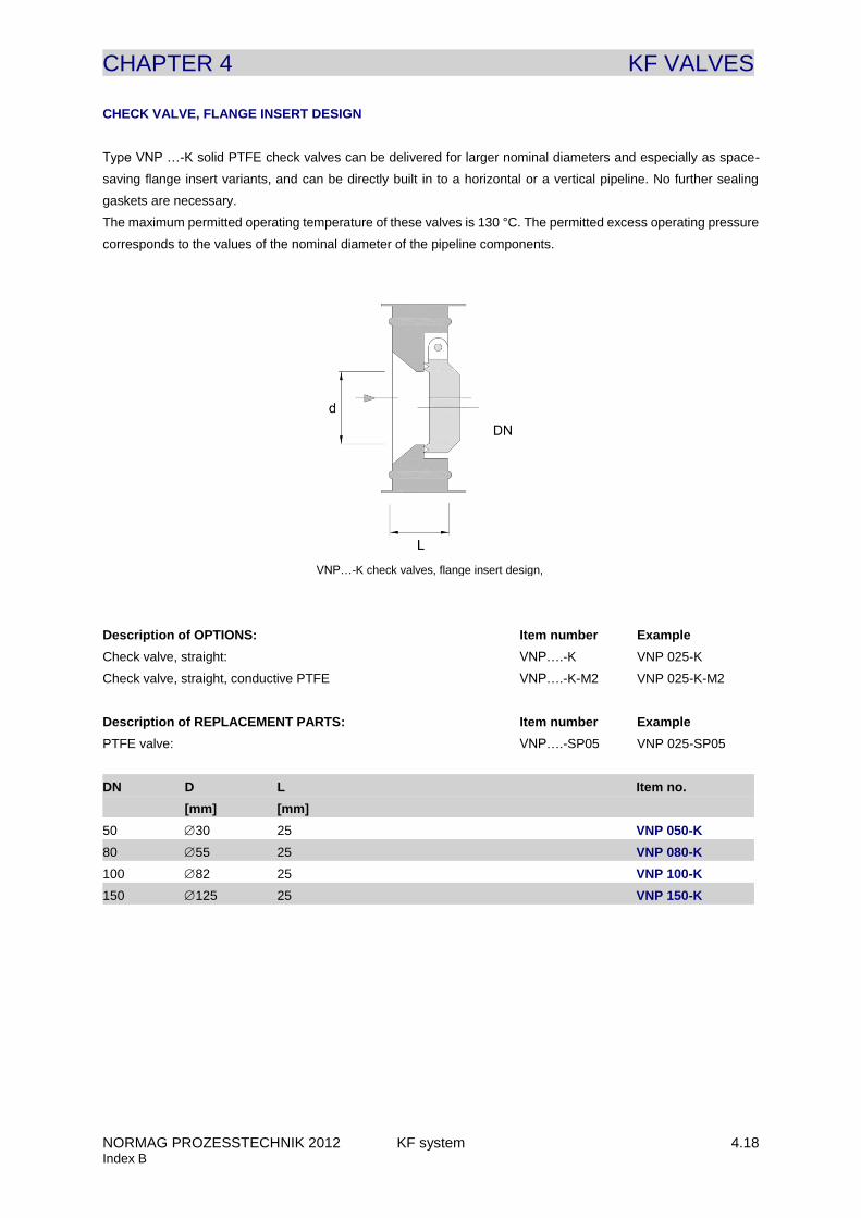
CHECK VALVE, FLANGE INSERT DESIGN
Type VNP …-K solid PTFE check valves can be delivered for larger nominal diameters and especially as space-
saving flange insert variants, and can be directly built in to a horizontal or a vertical pipeline. No further sealing
gaskets are necessary.
The maximum permitted operating temperature of these valves is 130 °C. The permitted excess operating pressure
corresponds to the values of the nominal diameter of the pipeline components.
Description of OPTIONS: Item number Example
Check valve, straight: VNP….-K VNP 025-K
Check valve, straight, conductive PTFE VNP….-K-M2 VNP 025-K-M2
Description of REPLACEMENT PARTS: Item number Example
PTFE valve: VNP….-SP05 VNP 025-SP05
DN D L Item no.
[mm] [mm]
50 30 25 VNP 050-K
80 55 25 VNP 080-K
100 82 25 VNP 100-K
150 125 25 VNP 150-K
VNP…-K check valves, flange insert design,
CHAPTER 4 KF VALVES
NORMAG PROZESSTECHNIK 2012 KF system 4.19 Index B
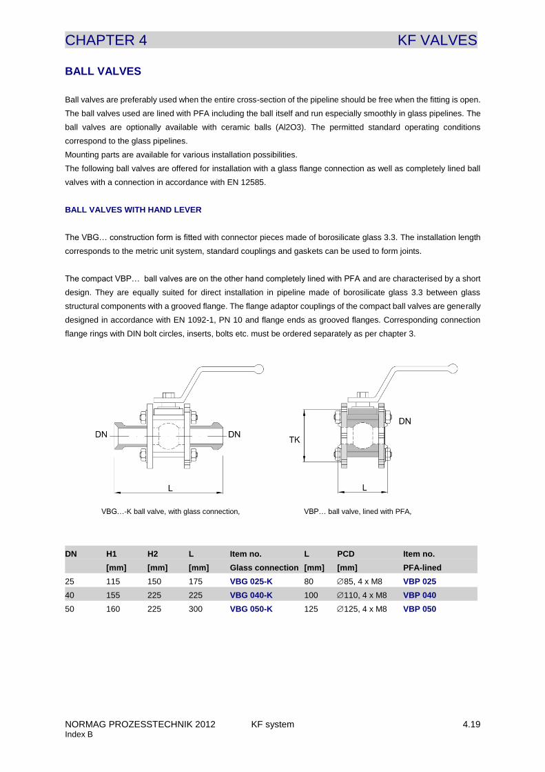
BALL VALVES
Ball valves are preferably used when the entire cross-section of the pipeline should be free when the fitting is open.
The ball valves used are lined with PFA including the ball itself and run especially smoothly in glass pipelines. The
ball valves are optionally available with ceramic balls (Al2O3). The permitted standard operating conditions
correspond to the glass pipelines.
Mounting parts are available for various installation possibilities.
The following ball valves are offered for installation with a glass flange connection as well as completely lined ball
valves with a connection in accordance with EN 12585.
BALL VALVES WITH HAND LEVER
The VBG… construction form is fitted with connector pieces made of borosilicate glass 3.3. The installation length
corresponds to the metric unit system, standard couplings and gaskets can be used to form joints.
The compact VBP… ball valves are on the other hand completely lined with PFA and are characterised by a short
design. They are equally suited for direct installation in pipeline made of borosilicate glass 3.3 between glass
structural components with a grooved flange. The flange adaptor couplings of the compact ball valves are generally
designed in accordance with EN 1092-1, PN 10 and flange ends as grooved flanges. Corresponding connection
flange rings with DIN bolt circles, inserts, bolts etc. must be ordered separately as per chapter 3.
DN H1 H2 L Item no. L PCD Item no.
[mm] [mm] [mm] Glass connection [mm] [mm] PFA-lined
25 115 150 175 VBG 025-K 80 85, 4 x M8 VBP 025
40 155 225 225 VBG 040-K 100 110, 4 x M8 VBP 040
50 160 225 300 VBG 050-K 125 125, 4 x M8 VBP 050
VBP… ball valve, lined with PFA, VBG…-K ball valve, with glass connection,
CHAPTER 4 KF VALVES
NORMAG PROZESSTECHNIK 2012 KF system 4.20 Index B
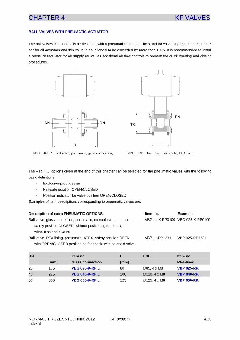
BALL VALVES WITH PNEUMATIC ACTUATOR
The ball valves can optionally be designed with a pneumatic actuator. The standard valve air pressure measures 6
bar for all actuators and this value is not allowed to be exceeded by more than 10 %. It is recommended to install
a pressure regulator for air supply as well as additional air flow controls to prevent too quick opening and closing
procedures.
FITTINGS
The – RP … options given at the end of this chapter can be selected for the pneumatic valves with the following
basic definitions.
- Explosion-proof design
- Fail-safe position OPEN/CLOSED
- Position indicator for valve position OPEN/CLOSED
Examples of item descriptions corresponding to pneumatic valves are:
Description of extra PNEUMATIC OPTIONS: Item no. Example
Ball valve, glass connection, pneumatic, no explosion protection, VBG….-K-RP0100 VBG 025-K-RP0100
safety position CLOSED, without positioning feedback,
without solenoid valve
Ball valve, PFA lining, pneumatic, ATEX, safety position OPEN, VBP….-RP1231 VBP 025-RP1231
with OPEN/CLOSED positioning feedback, with solenoid valve:
DN L Item no. L PCD Item no.
[mm] Glass connection [mm] PFA-lined
25 175 VBG 025-K-RP… 80 85, 4 x M8 VBP 025-RP…
40 225 VBG 040-K-RP… 100 110, 4 x M8 VBP 040-RP…
50 300 VBG 050-K-RP… 125 125, 4 x M8 VBP 050-RP…
VBG…-K-RP… ball valve, pneumatic, glass connection, VBP…-RP… ball valve, pneumatic, PFA-lined,
CHAPTER 4 KF VALVES
NORMAG PROZESSTECHNIK 2012 KF system 4.21 Index B
FLAPS
For larger nominal diameters between DN 80 and DN 300 flaps are available in addition to the ball valves. The flaps
are completely PFA-lined, gas-tight and suitable as flow regulator. The flaps are designed with a hand lever (DN
80) or a worm drive with a hand wheel (DN 100 – DN 300), however on request they can also be designed with a
pneumatic drive.
The permitted operating conditions for the flaps should be adjusted individually for the glass equipment or preceding
apparatus such as enamel reactors.
Mounting parts are available for various installation possibilities.
It is possible to form a joint with branches of glass piping or enamelled steel tubes. The necessary adaptor couplings,
see chap. 3 »couplings«, are to be ordered separately.
CHAPTER 4 KF VALVES
NORMAG PROZESSTECHNIK 2012 KF system 4.22 Index B
APPARATUS AND SPECIAL VALVES
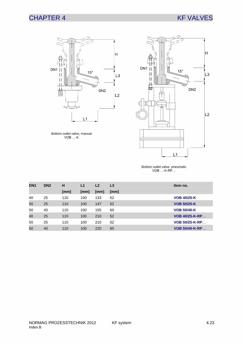
BOTTOM OUTLET VALVES
Bottom outlet valves are suitable as outlet valves which reduce dead space and are used in spherical and cylindrical
vessels whose glass joint Bottom is made of borosilicate glass 3.3. The angled outlet valves and the radial sealing
of the plunger in the glass joint ensure a residue-free outflow. In addition to the sealing on the valve housing, a
safety seal is attached up to the valve bonnet, which also guarantees high seal tightness during large temperature
fluctuations.
Optionally a GMP optimized version with a bellow with round folds is available. Riboflavin tests showed a residue-
free draining of this design.
Standard designs of Bottom outlet valves are made for a Bottom connecting piece with a length H of 95-115 mm.
For lengths H which differ from this the desired length should be entered using option “L” as in the following example.
In addition to the length of the connection piece there are also numerous further options for Bottom outlet valves
such as temperature measurement in the vessel’s Bottom connector piece. To do this, a PT100-, 4-wire, class A
resistance thermometer with ATEX certification II 2G Ex e II, is integrated.
To connect the Bottom outlet valves to the connector pieces of the spherical or cylindrical vessel a standard type
CGG sealing gasket is used and a type CAPG …-K adaptor coupling in accordance with chapter 3 with an additional
length of 50 mm (e.g. CGG040-K and CAPG040-K-L0050).
Description of OPTIONS: Item number Example
Bottom outlet valve, manual: VOB….-K VOB 40/25-K
Bottom outlet valve, manual, with a height H = 70 mm*: VOB….-K-L0070 VOB 40/25-K-L0070
Bottom outlet valve, manual, conductive PTFE with earthing: VOB….-K-M2 VOB 40/25-K-M2
Bottom outlet valve, manual, conductive PTFE & coating. VOB….-K-C3-M2 VOB 40/25-K-C3-M2
Bottom outlet valve, manual, conductive PTFE & temp.sensor: VOB….-K-M2-T2 VOB 40/25-K-M2-T2
Bottom outlet valve, manual, with round bellows: VOB….-K-M3 VOB 40/25-K-M3
Bottom outlet valve, pneum., not EX-proof, safety pos. OFF**: VOB….-K-RP0100 VOB 40/25-K-RP0100
Description of REPLACEMENT PARTS: Item number Example
Conical valve seal, PF system: VOB….-K-SP05 VOB 25-K-SP05
* Special lengths H differing from the standard length H = 100 mm are possible. Typical cases are Bottom
outlet connectors with H= 0 mm (connection to a block flange e.g. in an enamelled or stainless steel vessel),
H = 70 mm (single-walled vessel), H = 100 mm (jacketed vessel) und H = 125 mm (triple-walled vessel).
** RP … can be specified for pneumatic Bottom outlet valves according to the option list whereas for Bottom
outlet valves only the ATEX option and fail-safe position can be selected. The necessary air supply pressure
measures 2.5 bar and may only be exceeded by 10 %.
CHAPTER 4 KF VALVES
NORMAG PROZESSTECHNIK 2012 KF system 4.23 Index B
DN1 DN2 H L1 L2 L3 Item no.
[mm] [mm] [mm] [mm]
40 25 110 100 133 52 VOB 40/25-K
50 25 110 100 147 52 VOB 50/25-K
50 40 110 100 155 60 VOB 50/40-K
40 25 110 100 210 52 VOB 40/25-K-RP…
50 25 110 100 210 52 VOB 50/25-K-RP…
50 40 110 100 220 60 VOB 50/40-K-RP…
Bottom outlet valve, manual VOB …-K
Bottom outlet valve, pneumatic VOB …-K-RP…
CHAPTER 4 KF VALVES
NORMAG PROZESSTECHNIK 2012 KF system 4.24 Index B
Further apparatus and special fittings are:
ADJUSTABLE OVERFLOW VALVES
Adjustable overflow valves are used to regulate the separation levels in liquid-liquid separators, azeotrope columns
or similar apparatus. The height adjustment is carried out with a hand wheel and a PTFE overflow pipe with bellows.
Details on the adjustable overflow valves can be found in chapter »apparatus« for horizontal separators and mixer
settlers.
GAS MIXING VALVES
Gas mixing valves are used to insert and dissolve gas into liquids, mostly in bubble columns or reaction vessels.
Here, the gas is fed through radial holes at the smallest cross-section of the PTFE nozzle and carried away by the
liquid current flowing past and distributed into the smallest of bubbles. The bubbles therefore distribute themselves
evenly in the liquid so that a very good solubility and reaction rate are ensured.
For detailed questions, e.g. on the possible relationship between liquid and gas flow-rate and on the necessary inlet
pressures, as well as for a specific quote, please contact our specialist department.
MEMBRANE VALVES
Membrane valves are rarely used in the construction of glass apparatus. Membrane valves generally consist of a
glass base body and a sealing PTFE membrane on a glass saddle. This enables the valve to be completely emptied
through connected pipelines when it is installed vertically and it this means it is also suitable for GMP applications.
Standard designs of membrane valves are available with a hand wheel and a pneumatic actuator is optionally
available.
CHAPTER 4 KF VALVES
NORMAG PROZESSTECHNIK 2012 KF system O 4.1 Index B
OPTIONS VALVES
For valves the following options can be chosen in addition to the standard structural components. Each option
chosen must be entered at the end of the item number. Several options can be chosen and they are presented as
far as possible in alphabetical order. In the following table you will find examples of item numbering for additional
options.
Product name: Item number Examples
KF angle valve: VE DN-K VE 025-K
KF angle valve, with conductive coating: VE DN-K-C3 VE 025-K-C3
KF angle valve,, with material certificate: VE DN-K-Z2 VE 025-K-Z2
KF angle valve, with conductive coating and material certificate: VE DN-K-C3-Z2 VE 025-K-C3-Z2
KF angle valve, with conductive coating, conductive PTFE, earthing,
flexible operating extension 1 m, FDA material certificate: VE DN-K-C3-H21-Z1 VE 025-K-C3-H21-Z1
You can choose from the following options:
OPTION C – COATING / GLASS TYPE
The standard components used are those made of borosilicate glass 3.3 without coating. The following alternative
options are possible:
C1 = coating, non-conductive
C2 = coating, non-conductive, for higher temperatures and chemical resistance
C3 = coating, conductive
C4 = amber glass
C5 = quartz glass
OPTION F – FLANGE TYPE
The standard components used are made of borosilicate glass 3.3 with the flange type F4 (PF system).
The following flange connectors for glass structural components are also generally available:
F1 = KF flanges, type KF../1
F2 = KF flanges, type KF../2
F3 = KF flanges, type KF../3
F4 = PF flanges, type PF
F5 = Tube connection 16 mm
F6 = Tube connection 26 mm
F7 = GL-thread GL 18
F8 = GL-thread GL 25
F9 = NS 29/32
F10 = NS 45/40
All other combinations of the flange types F1 to F4 can be selected as options, we will be happy to check whether
the other types of flange can be used with your desired structural component.
CHAPTER 4 KF VALVES
NORMAG PROZESSTECHNIK 2012 KF system O 4.2 Index B
OPTION H – FLEXIBLE OPERATIONAL EXTENSION
Standard = without shaft extension
H10 = 0.5 m flexible shaft extension, G3/4" stainless steel connector
H20 = 1.0 m flexible shaft extension, G3/4" stainless steel connector
H30 = 1.5 m flexible shaft extension, G3/4" stainless steel connector
H40 = 2.0 m flexible shaft extension, G3/4" stainless steel connector
H11 = 0.5 m flexible shaft extension, G1" stainless steel connector
H21 = 1.0 m flexible shaft extension, G1" stainless steel connector
H31 = 1.5 m flexible shaft extension, G1" stainless steel connector
H41 = 2.0 m flexible shaft extension, G1" stainless steel connector
H12 = 0.5 m flexible shaft extension, G1 1/4" stainless steel connector
H22 = 1.0 m flexible shaft extension, G1 1/4" stainless steel connector
H32 = 1.5 m flexible shaft extension, G1 1/4" stainless steel connector
H42 = 2.0 m flexible shaft extension, G1 1/4" stainless steel connector
OPTION M – MATERIAL / PTFE-DESIGN
The standard design is in white PTFE, non-conductive and with no material certificate.
M1 = PTFE conductive
M2 = PTFE conductive with earthing
M3 = PTFE-valve plunger with round bellows, white PTFE, FDA material certificate
The option M choice selection only applies for valves.
OPTION O – SPECIAL OPTIONS
The following special options are offered for certain structural components.
O1 = plastic valve bonnet, free of non-ferrous metals
O2 = stainless steel valve bonnet
O3 = manual valve design with positioning feedback OFF,
ATEX conform positioning feedback, protection class II 2G Ex ia IIC T6, 3 m long
O4 = valve lifting lever (only for type VP pressure relief valves)
O5 = number of valves on multiple distributors, for example the multiple distributor with three valves is option O53,
and with four valves option O54, etc..
O6 = hollow ball in vertical ball check valves
O7 = manual type VNV lifting lever device in vertical ball check valves
O8 = flange insert version for type VNV check valves
O9 = flange insert version for type VNV check valves and manual lifting lever device.
O10 = KF-valve in former design (without reduced diameter valve seat and connection)
O11 = plastic screw cap and chain (for valves with GL threaded outlet)
CHAPTER 4 KF VALVES
NORMAG PROZESSTECHNIK 2012 KF system O 4.3 Index B
OPTION R – CONTROL VALVES AND PNEUMATIC ACTUATORS
Enter option RC … for the control function as Kvs value for a linear control characteristic
RC = Kvs value of the fitting to one decimal place, e.g. “-RC160” for Kvs value 16.0
The pneumatic actuator can be delivered with the following RP …options:
RP w _ _ _ = ATEX-design:
w=0: no explosion-proof design
w=1: ATEX design, all relevant components of the actuator in protection class II 2G EEx ia IIC T6.
According to EX-zone (in / out) of the valve additional requirements can be necessary
or recommendable (conductive PTFE with earthing (option –M2), electrically conductive glass
coating (option –C3)).
If you have questions you are welcome to contact our specialist department.
RP _ x _ _ = Fail-safe position:
x=0: without safety position / double acting pneumatic
x=1: safety position “spring closed”
x=2: safety position “spring open”
RP _ _ y _ = Limit switch with built-in inductive proximity switches:
y=0: without signalling of ON or OFF position
y=1: Signalling of ON
y=2: Signalling of OFF
y=3: Signalling of ON and OFF
y=4*: Built-in analogue positioning feedback (4...20 mA)
RP _ _ _ z = design
z=0: without solenoid valve in the pneumatic valve actuator
z=1: with solenoid valve in the pneumatic valve actuator,
3/2-way solenoid valve design
* only for control valves and possible instead of proximity switches
OPTION SP – REPLACEMENT PARTS
The replacement parts for the individual fittings are entered for each individual valve.
OPTION TAG – LABELLING
Standard labelling of glass structural components is carried out using the standard item number or special
identification number, however without an individual TAG number.
TAG numbering is available to individually number the valves. To do this enter the option TAG and provide us
separately with the desired TAG numbering for the particular valve types.
TAG = with TAG numbering
CHAPTER 4 KF VALVES
NORMAG PROZESSTECHNIK 2012 KF system O 4.4 Index B
OPTION T – TEMPERATURE PROBE
The standard design comes without a temperature probe.
Temperature probes can also optionally be integrated for Bottom outlet valves.
The individual options for this are:
T1 = with temperature probe
T2 = with temperature probe, ATEX conform with protection class II 2G Ex ia IIB T6
OPTION V – VACUUM RESISTANCE / - OPERATION
With this option components that are explicitly only suitable for atmospheric or excess operational pressure are
also suitable for operation in vacuum conditions. This affects the type VSL sampling valve for pipelines from this
chapter.
V = vacuum resistance or suitable for vacuum operation
OPTION Z – CERTIFICATES
Standard deliveries do not come with certificates.
The following certificates can optionally be delivered with your order.
Z1 = FDA material certificate1)
Z2 = material certificate 2.2
Z3 = Certificate for Technical Guidelines on Air Quality Control (TA-Luft)
Z4 = calibration certificate for control valves
1) FDA material certificates can be delivered for product-side structural components containing PTFE.