Embed Size (px)
Citation preview

N76 11824CHAPTER 5
Active Microwave Sensor Technology
Active Microwave Working Group
Technology Support Group:
WALTER E. BROWN, JR., CochairmanM. I. SKOLNIK, Cochairman
Louis H. BauerChi-Hau ChenD. E. N. DaviesRichard G. FennerH. L. GroginskyPreben E. Gudmandsen
Donald HowellRolando JordanRichard W. LarsonLeonard J. PorcelloGerald G. SchaberF. C. Williams
INTRODUCTION
Radar technology is concerned with waysand means to provide information about areflecting area. During the past two decades,major advancements have been made in thistechnology, and sophisticated techniques havebeen developed for locating the direction andrange to a reflecting area. Furthermore,other characteristics of the reflection, suchas amplitude, phase, Doppler frequency, andpolarization, have been used to identify ad-ditional properties of the target area. Theradar provides its own illumination, andthere is no question that the target informa-tion contained in the echo is unique. Thewavelength, bandwidth, polarization, andmodulation of the illuminating signal areselectable by the experimenter, thus provid-ing a wide choice of operational parametersover a frequency spectrum of approximatelythree decades (150 MHz to 150 GHz).
The amount of information concerning atarget area contained in the echo (reflection)is enormous. For example, a comparison
between a photographic picture element(pixel) (visible spectrum), which has a highinformation content, and an element of aradar image is shown in table 5-1.
The radar echo per unit areal elementcontains as much or more information thanthe photograph. Each representation of thetarget area contains unique information be-cause the wavelength range is different, andthe surface reflection represents the responseto the respective illumination wavelengths.
TABLE 5-1.—A Comparison of Photographicand Active Microivave Data Content
Photographic pixelX-angleY-angleFrequency (color)AlbedoPolarizationNo comparables
Radar imageX-angleY-angle ..FrequencyAmplitudePolarizationPhase (absolute)DopplerPhase jitter ^
369
RECEDING PAGE BLANK NOT FUMED
https://ntrs.nasa.gov/search.jsp?R=19760004736 2018-08-05T06:32:16+00:00Z
370 ACTIVE MICROWAVE WORKSHOP REPORT
For example, a wheatfield can be observed onboth an areal photograph and a radar image.The two output sensor images do not neces-sarily contain the same information becausethe image areas may be covered by a wide-wavelength separation, from 3 x 10~5 to 25cm. Because each image has a differentinformation content, the wheatfield may be"visible" to one sensor or the other, or both.The objectives are to determine the relation-ship between the surface property and theecho characteristic and to enhance the effectsto reduce the measurement uncertainty. Thisarea is a major endeavor for radar tech-nology.
One purpose of this chapter is to providea link between the recommendations of thescience or application studies and the imple-mentation aspects of the radar. Thus, thetechnology support group (TSG) has con-tributed comments on feasibility, suggestedbaseline functional descriptions of the vari-ous types of active microwave sensors, andsubmitted some examples of existing radartechniques and examples of the results. Thischapter also includes an example of how thedata are used to obtain scientific results.Data handling, particularly for high-rateinformation systems (i.e., imaging radar),is a major problem area. Hence, a specialsection has been devoted to the data-manage-ment aspects. The last section is concernedwith future development and reflects the
concern of technologists for obtaining factualinformation about the measurement process.
Science and Application Guidelines
The various science and applications meas-urement recommendations were compiledand summarized to determine how manydifferent types of systems may be requiredand to ascertain the major categories ofessential microwave sensor parameters.These summaries are intended to serve onlyas guidelines for instrument development,not as specifications.
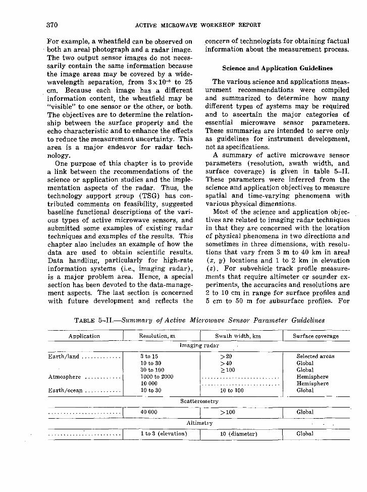
A summary of active microwave sensorparameters (resolution, swath width, andsurface coverage) is given in table 5-II.These parameters were inferred from thescience and application objectives to measurespatial and time-varying phenomena withvarious physical dimensions.
Most of the science and application objec-tives are related to imaging radar techniquesin that they are concerned with the locationof physical phenomena in two directions andsometimes in three dimensions, with resolu-tions that vary from 3 m to 40 km in areal(x, y) locations and 1 to 2 km in elevation(z). For subvehicle track profile measure-ments that require altimeter or sounder ex-periments, the accuracies and resolutions are2 to 10 cm in range for surface profiles and5 cm to 50 m for subsurface profiles. For
TABLE 5-II.—Summary of Active Microwave Sensor Parameter Guidelines
Application Resolution, m Swath width, km Surface coverageImaging radar
Earth/land
Atmosphere
Earth/ocean
3 to 1510 to 3030 to 1001000 to 20001000010 to 30
>20>40>100
10 to 100
Selected areasGlobalGlobalHemisphereHemisphereGlobal
Scatterometry
40000 >100 Global
Altimetry
1 to 3 (elevation) 10 (diameter) Global

ACTIVE MICROWAVE SENSOR TECHNOLOGY 371
upper surface profiles (i.e., cloud water),accuracies of approximately 1 km would beuseful. One other sounder, the surface pres-sure sensor, would be measuring the slope ofthe oxygen absorption line to within a frac-tion of 1 percent. The following are the moststringent requirements:
1. Amplitude: Generally within 15 percent.2. Dynamic range: 50 dB.3. Polarization: Within 1°.4. Range (time delay) : 2 to 10 cm (1Q-10
sec) (correction for variations in index ofrefraction not expressed).
5. Frequency: Within 10 percent.6. Phase: Within 5°.7. Doppler frequency: Within 1 percent.
A large majority of the ocean and Earth/land science and application objectives couldbe realized with a single imaging radar sys-tem operating perhaps in various modes (inincident angle, swath width, or resolution).There are some special-purpose radar sys-tems required for geoid measurements andsurface-wind determination.
The atmospheric science and applicationsobjectives have, in general, a different classof radar design criteria. The discussion ofthese criteria is contained in chapter 4.
The surface-sounding radar requirementsare, in a sense, an extension of the altimeterradar design and may be restricted to air-craft programs for the next several years.
General System Considerations
The design of imaging radar systems forspacecraft leads to a set of system parametersthat are interrelated. A change in one param-eter implies changes in most of the others.This section will delineate some of the trade-offs required for an acceptable system.
The antenna design is one of greatestimportance because its proper selection isrequired to give an image with low am-biguous returns in either range or azimuth.The theoretical azimuthal resolution of asynthetic aperture radar (SAR) system isequal to one-half of the along-track length ofthe antenna. However, a small azimuthalbeamwidth returns energy with a high Dop-
pler bandwidth. To unambiguously samplethe data, according to the Nyquist criteria, ahigh pulse repetition frequency (PRF) mustbe used. Thus, to avoid successive pulsemixing, the radiation of the antenna must beconfined to a narrow set of angles in thecrosstrack dimension, which results in alarge antenna dimension in the crosstrackdimension (fig. 5-1).
Smaller antenna azimuth(along-track dimension) length- • Better azimuth resolution
Wider beam
ILarger Doppler shift
IHigher PRF
ISmaller range beamwidth to avoid pulse
mixing or range ambiguity
Larger antenna range (crosstrack dimension) length andsmaller swath width
FIGURE 5-1.—Diagram showing that a decrease inone dimension of the antenna requires an increasein the other dimension to avoid ambiguities.

372 ACTIVE MICROWAVE WORKSHOP REPORT
Given a required swath width or PRF, theantenna length in azimuth must be suffi-ciently large to limit radiation in the azimuthdimension to give low azimuthal ambiguities.These ambiguities are returns from areasother than the area being imaged, which,when sampled periodically and processed,map in identical locations as those of thedesired surface returns. These ambiguitiesare reduced by sampling the data with sev-eral pulses (2 to 5) every time the spacecraftmoves a distance equal to the antenna length.The illumination pattern of. the antenna maybe weighted to minimize the returns comingin through the antenna side lobes. In therange dimension, ambiguities can also resultfrom successive pulse mixing, and theseambiguities are again reduced by limitingradiation by means of a large crosstrackantenna with illumination tapering. Theimplication of this antenna design, to keepambiguities at a low level at orbital altitudes,results in a required minimum antenna areathat follows a curve such as that shown infigure 5-2 for variations in spacecraft oraircraft altitudes. The antenna look anglealso has a significant effect on the minimumarea required for unambiguous illuminationof the surface. As the antenna crosstracklength is increased from the nadir direction,
50,-
40
:30
20
10
L-band,
X-band.
200 400 600 800 1000Spacecraft altitude, km
1200 1400
FIGURE 5-2.—Minimum antenna area required for X-and L-band radar systems with a 30° look anglefrom nadir.
the resultant echo shape is increased in dura-tion. Thus, for a given PRF, to avoid con-secutive pulse mixing, the radiation must beconfined to look-angle widths, which, in turn,implies longer antenna crosstrack dimen-sions. The required antenna area then varieswith the look angle as shown in figure 5-3.Another factor that will be affected by rais-ing the look angle for a given system band-width is the radar system range resolution(fig. 5-3).
The transmitter power required to yieldan acceptable image is another parameterthat needs careful consideration. The follow-ing information is required before theseparameters may be determined:
1. The minimum detectable backscattercoefficient required of the radar.
2. The angle of incidence necessary for themeasurement.
3. The necessary resolution.4. The antenna characteristics.
The orbital characteristics presumably areknown. For a given set of user conditions,the radiated power average required variesinversely with wavelength unless sophisti-cated multiple-feed antenna systems are used.Figure 5-4 shows a plot of the transmitterpower required for a system with a 15° in-cident angle and is indicative of the depend-ence of power on wavelength. Thus, if wave-length is not a user requirement, a tradeoffbetween power and antenna area is involvedin wavelength selection.
The accuracy (relative or absolute) of themeasurement is one parameter having a greatimpact on the capability of an imaging radarsystem to measure a given phenomenon. Theside-looking coherent imaging radar systemprovides the user a measure of the radar-backscatter coefficient of each resolution ele-ment on the surface being imaged. Becauseof numerous factors, this measurement willhave an uncertainty in its absolute value.However, through careful design and imple-mentation, this uncertainty can be reducedto arbitrarily low values at the expense ofcomplexity, power, weight, etc.
A given resolution element, when illumi-

ACTIVE MICROWAVE SENSOR TECHNOLOGY 373
100 r 100 r
SOf
Of
90
80
70
60
50
40
30
20
10
0
90
80
70
~e 60
(O£ccO)
I 40
30
20
10
1000
Antenna area
._ Resolution*»»*
10 20 30 40 50 60Look angle, deg
FIGURE 5-3.—Required antenna area and resolutionas a function of incident angle.
nated by a coherent source of electromagneticenergy, will exhibit a variation in its meas-ured backscatter value as the antenna movesin location. This effect is known as targetscintillation or "speckle." This variation isalso observed when a large number of returnsare added coherently to improve systemresolution, which is done with a syntheticaperture system. To reduce the error in theestimated value of the backscatter coefficientof the resolution element being observed, themeasurement process can be made repeatedly,and the measured values can be added non-coherently. Coherent addition implies thatboth quadrature elements of the measure-ment are added vectorially; whereas, innoncoherent addition, only the magnitudeof the resultant vector is added. This conceptof separate or independent measurementstaken and summed is also known as multiple-look processing or noncoherent averaging inan SAR system. Thus, as a prime considera-tion early in the study of a potential imaging
500
200
100
67
56
S
I45O)
34
23
25 r
20
.15
10
Antenna area
.05 .1 .2 .3Wavelength, m
.4
FIGURE 5-4.—Antenna area, radar power, and weightas a function of wavelength for a single feed an-tenna system at an altitude of 1000 km, with a 70-km swath width, 33- by 33-m resolution, and 15°look angle.
radar system, it is necessary to know thedegree of precision to which a measurementat each resolution element must be made sothat the user is able to accomplish his re-quired task. The implementation implica-tions of multiple-look processing are many.The major impact lies in the data-reductionprocess and, to some extent, in radiatedpower.
If the data-reduction process is accom-plished on board a spacecraft, then each sep-arate or independent look requires a separatedigital processor. If the looks are accom-plished in azimuth, then a large two-dimen-sional buffer is required to combine theseparate looks that are gathered at slightlydifferent delays. If the data-reduction processis accomplished on the ground, then a largedata telemetry system or data storage deviceis required.
The data rate that the radar system willgenerate is similar to that of a photographicsystem and depends on the swath width,resolution, and vehicle velocity. If multiple-look processing is involved, this factor willalso affect the data rate, if the data are

374 ACTIVE MICROWAVE WORKSHOP REPORT
recorded or telemetered to Earth unproc-essed. The data rate DRr out of the radarsystem is given approximately as
DRr=2NrlNLvSr
rrra(5-1)
where Nrl is number of bits per data sample,NL is number of looks, v is vehicle velocity,Sr is swath width, rr is range resolution, andra is azimuth resolution. The data rate DRr
out of the digital processor is given by thefollowing equation:
DRr = r,-ra(5-2)
where N,.2 is the number of processor bits perdata sample. These two equations differ bythe ratio
2NnNLN,.2
(5-3)
In general, Nn will always be smaller thanNr,. However, the data rate out of theprocessor will be somewhat smaller than theradar system output, particularly if multiplelooks are involved. The complexity of anonboard processor must be considered in anydecision for its inclusion.
The following criteria must be satisfied tomake a proposed application attractive in anoverall sense:
1. The application or mission must have adegree of national importance or benefit thatjustifies the cost.
2. The technology either must be availableor must be attainable with an acceptable levelof risk.
3. The radar signature base and the pro-posed data-analysis techniques either mustbe available or must be attainable with highprobability.
The judgment and applications pertainingto the first and second criteria are probablyoutside the scope of this workshop. However,the TSG believes that current technology andunderstanding of signature bases and analy-sis techniques are sufficiently advanced sothat several of the proposed applications
appear highly attractive in terms of thesecond and third criteria. These applicationshave relatively low technical risks and there-fore will offer a high possibility of successfrom a purely technological viewpoint. Ifany of these same applications also happento be cost-effective from a national viewpoint,then they lead to excellent candidate missionsupon which to base a long-term program. Ofcourse, none of the proposed applications aretotally without problems, and each requiressome level of further study and techniquedevelopment, which will need to be plannedand implemented.
Applications that appear to be low riskfrom a technological viewpoint include thefollowing:
1. Use of an imaging radar for a varietyof ice surveillance roles, including determi-nation of the ice lead and polynya structureat high latitudes, iceberg detection in ship-ping lanes, monitoring drift and decay oficebergs off Antarctica, and lake-ice recon-naissance in the Great Lakes and St. Law-rence River shipping lanes.
2. Use of a radar profilometer for gen-erating profiles of the ocean surface on aglobal scale, building upon the experienceachieved in the Skylab S193 experiment andother experiments.
3. Use of a radar scatterometer for wind-speed estimation for inputs to global weathermodels.
4. Use of an imaging radar for the obser-vation of geologic structure and lithology.
5. Use of an imaging radar for a varietyof applications that stem from the ability toobserve land/water boundaries. (These ap-plications include observations of lake levelsand stream overflow, the analysis of water-shed runoff, and the study of coastal andshoreline features.)
6. Use of an imaging radar for observa-tions of ocean-surface patterns on a globalbasis.
7. Use of an imaging radar for gross land-use classification.
8. Use of a suitable multiband imagingradar with sophisticated analysis techniques

ACTIVE MICROWAVE SENSOR TECHNOLOGY 375
for estimation of crop acreage in agriculturalcontexts characterized by a small number ofpossible crops and moderate to large fields.
This list is not meant to be exhaustive. Itreflects, in large part, the experience andcomprehension of TSG members.
PART A
FUNCTIONAL DESCRIPTIONS OF SELECTED ACTIVE MICROWAVE SYSTEMS
In chapters 2, 3, and 4 of this document,the Earth/land panel, oceans panel, andatmosphere panel, respectively, have estab-lished requirements for several active mi-crowave measurements. Although certaincommon features are present in these meas-urements, several basic types of measure-ments can be distinguished, and a class ofsensors can be associated with each type.
MAJOR CLASSES OF CANDIDATE SYSTEMS
The following four classes of active micro-wave measuring systems appear to offer thegreatest utility to the three user panels:
1. Scatterometers designed to measureelectromagnetic scattering properties ofsurfaces (without emphasis on spatial reso-lution) .
2. Altimeters designed to accurately meas-ure the vertical distance between the sensorand the scattering surface directly beneathit or to profile the surface beneath it.
3. Sounders designed to penetrate theuppermost boundary of the medium beneaththe sensor and to observe the vertical struc-ture of this medium by means of a delicatebalance between reflection due to verticalgradients and transmission through thesegradients.
4. Imaging systems designed to measurethe scattering properties of surfaces, usuallywith lateral spatial resolution finer than thatrequired in any of the preceding classes.
Other useful radar-measuring configura-tions (e.g., a Doppler radar designed toobserve the radial velocities of scatterers)can be treated in an analogous manner, but
these configurations will be omitted in thisreport because they are less critical to thestated needs of the user panels.
For the purpose of this document, the term"functional description" will be a descriptionof an active microwave system that answersthe following fundamental questions:
1. What physical attribute of the scattererdoes the system measure?
2. How does the system perform the meas-urement?
3. What are the principal parameters thatcharacterize the output of the system?
4. In what form is the output provided tothe user?
5. What are the principal sources of meas-uring system error, and how do they affectperformance ?
Questions 1 to 5 relate to figure 5-5. Theanswer to question 1 describes the input interms meaningful to the sensor. Question 2applies to the "transfer characteristic" of themeasuring system, whereas question 3describes the output in terms consistent withquestions 1 and 2. Question 4, strictly aformat question, may be critical to proper
Input• Output
Errorsources
FIGURE 5-5.—Diagram of the basic measurementprocess.

376 ACTIVE MICROWAVE WORKSHOP REPORT
data management. Question 5 is self-ex-planatory.
The topics of parameter interplays andsystem design tradeoffs sometimes are in-cluded in a functional description of a system.In general terms, a functional descriptionprovides a mathematical model on which tobase a design exercise, whereas the param-eter tradeoff question relates to the questionof optimizing a design for a specific mission.However, a discussion of tradeoffs does pro-vide useful insights and is included for someof the sensors.
Finally, two additional questions may arisein a functional description:
6. What level of performance does currenttechnology permit, and how may this per-formance level be extrapolated into thefuture?
7. What are order-of-magnitude estimatesof weight, power, volume, cost, expectedlifetime, and other variables that are poten-tially important in experiment selection andplanning?
The answers to these last two questionsmust come from design exercises that beginwith a set of proposed mission objectives anddesign constraints and that are then op-timized over all variables.
FUNCTIONAL DESCRIPTIONS BY CLASS
In this section, functional descriptions ofthe four principal classes of active microwavesensors are provided.
Radar Scatterometer
The radar scatterometer is a special-pur-pose instrument that measures the relativevalue of the radar-backscatter coefficient ata range of angles. Because no spatial resolu-tion is required other than the area illumi-nated by the antenna, this system is lesscomplex than other systems that require ahigh degree of spatial resolution. The datarate generated by a scatterometer is alsomuch lower than imaging systems becausethe coarser resolution does not require closespatial sampling of the surface. Measure-
ments of the relative radar-backscattercoefficient of the surface at various angles,polarizations, and wavelengths are used toinfer characteristics regarding the surface(such as wind velocity and direction for theocean and surface roughness for the land).
The scatterometer measures the microwavebackscatter cross section of a surface forvarious angles of incidence. During flightover an area of interest, radar backscatter asa function of incident angle is generatedfrom which some physical attributes of thesurface can be inferred. These measurementsmay be taken at different polarizations orwavelengths to enhance interpretation of thesurface characteristics. These measurementsare taken by illuminating the surface withmicrowave energy and measuring the por-tion of this energy that is reflected back to thetransmitting/receiving antenna. The outputof the scatterometer system is a set of datapoints corresponding to radar-backscattermeasurements as a function of angle andspacecraft position. These data are presentedto the user as a plot of radar backscatter asa function of angle for each data cell on thesurface.
System noise is the primary source of errorin the measurement of radar backscatter.Radar scatter ometer s. have been built thatmeasure a minimum backscatter coefficientof —30 dB. However, this does not in anyway mean that more sensitive microwavescatterometers cannot be built. Most ob-served phenomena have backscatter coeffi-cients exceeding this value. Because of thesimplicity of the radar scatterometer, itsweight^ excluding the antenna system, isusually in the tens of kilograms and powerconsumption is in tens of watts. Thus, thescatterometer is suitable for spacecraft use.
The scatterometer consists of (1) a micro-wave transmitter, (2) an antenna, (3) amicrowave receiver, and (4) a detector anddata integrator. Variation of these four basiccomponents results in the two basic scatter-ometer types: the beamwidth-limited scat-terometer and the pulse-width-limitedscatterometer.

ACTIVE MICROWAVE SENSOR TECHNOLOGY 377
The beamwidth-limited scatterometer con-sists of a long-pulse-width transmitter, apencil-beam antenna, a microwave receiverand down-converter, and a detector with anintegrator. The transmitter pulse is suffi-ciently long to simultaneously illuminate thearea of the antenna footprint. The returnenergy from the illuminated area is down-converted, amplified, narrow-bandpass-fil-tered, then square-law-detected and inte-grated as shown in figure 5-6. Because allthe energy entering the antenna illuminatesthe surface, the sensitivity of backspattercoefficient varies as the square of the rangeto the surface. To obtain a backscatterfunction from which to infer surface charac-teristics, the pencil-beam antenna will bescanned in elevation while measurements aretaken. In addition, the antenna may radiateand receive energy at different polarizationsas an aid in inferring surface characteristics.
The pulse-width-limited scatterometer dif-
Antenna
FIGURE 5-6.—Block diagram of scatterometer.
fers from the beamwidth-limited scatter-ometer in that a shorter pulse is transmittedto the surface by a fan-shaped antenna beam.The return echo is then time-gated to obtainelevation angle resolution. The receivedenergy processing is the same as that forthe beamwidth-limited scatterometer, exceptthat a number of channels are required forthe measurements. Each of these channelsis time-gated for a slightly different delayfrom the transmitted pulse, and, conse-quently, each of these channels processesenergy corresponding to a different range ofelevation angles from the spacecraft. Scan-ning of the antenna angle in elevation is notneeded to generate a backscatter function.As with the beamwidth-limited scatter-ometer, different polarizations can be usedas an aid to data interpretation.
Radar Altimeter
The radar altimeter has played an im-portant role in navigational and landingsystems for aircraft and spacecraft. Remote-sensing applications of radar altimetersimpose requirements for high measurementaccuracy that depend not only on the altim-eter but also on the control or monitoringof the motion of the platform on which thesystem is mounted.
To gain a proper perspective of the use ofan altimeter as a remote-sensing instrument,the basic operating principles of a simplealtimeter system will be considered. Figure5-7 shows a block diagram of a radar al-timeter that could represent several actualimplementations.
On command from the timing system, thetransmitter generates a modulated radio-frequency (rf) waveform that is directed bythe duplexer to the antenna port. The an-tenna directs the radiated energy toward thetarget surface and subsequently collects thatportion of the energy reflected or scatteredback in the direction of the antenna. Oncecollected by the antenna, the returned signalis directed by the duplexer to the receiverinput. The receiver processes the returnedsignal and provides an output from which

378 ACTIVE MICROWAVE WORKSHOP REPORT
AntennaTransmitter Timing
system
Rangemeasurement
systemData
FIGURE 5-7.—Block diagram of simplified radar al-timeter.
the two-way propagation delay can be deter-mined. Because the velocity of propagationis known, the range to the target may becomputed directly from the time-delaymeasurement.
To fully address the question of accuracyin terms of limiting factors, a particularimplementation must be specified (e.g.,frequency-modulated continuous wave, pulse,interrupted continuous wave (ICW), etc.),which, in many cases, is dictated by thegiven application. An in-depth discussion ofthe various radar altimeter implementationsis beyond the scope of this report; instead,a comment on those aspects of system ac-curacy that relate primarily to a givenapplication and that are common to all al-timeter systems is provided.
For the applications that require the truerange between the vehicle and the surface,some means of correcting for vehicle attitudeand altitude changes must be provided. Inaddition, the timing system must have highlong-term stability to insure that measure-ments made over a long period of time arerepeatable.
If profiling is the desired measurement(i.e., measurement of the variation in surfaceheight over a confined area), the long-termstability of the timing system needs to begood only for the desired measurementperiod, but measurement-to-measurement
stability must be extremely high. Again,fluctuation in the system platform attitudeand altitude can introduce serious errorsunless steps are taken to correct for suchvariations.
Measurement of surface roughness maynot require attitude or altitude correction,but measurement-to-measurement stability isstill required.
In general, the achievable accuracy of aradar altimeter system depends on the meas-urement type and frequency and on the par-ticular system implementation. Typicalrange measurements with present-day altim-eter systems can be made with an accuracyof ±30 m, whereas profiling measurementscan be made with an accuracy of ±60 cm.
Radio Subsurface Sounders
The radio subsurface sounder is a deviceto measure subsurface layers and boundaries.Radio subsurface sounders operate on thefollowing principles:
1. That low frequencies can penetrate thesurface of the Earth for some particularground situations.
2. That the power reflected back to thesounder can be detected.
3. That adequate resolution in range canbe realized.
This technique is only applicable to aircraftoperations because of the large reflectionfrom the air-surface boundary. Because theaircraft is at a given altitude above thesurface, this strong reflection can be removedby range gating and can.be minimized byviewing the surface at an incident angleother than normal. The special situations inwhich ground losses are small enough toenable the radio subsurface sounder to beuseful include the polar ice and the inlandice in Greenland and Antarctica. An experi-ment application for a radio subsurfacesounder is described in a subsequent section.
Image-Forming Radars
Of the various active microwave sensors,the imaging radar is most in demand. Radar
ACTIVE MICROWAVE SENSOR TECHNOLOGY 379
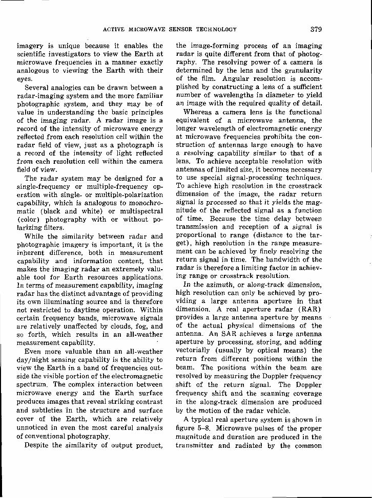
imagery is unique because it enables thescientific investigators to view the Earth atmicrowave frequencies in a manner exactlyanalogous to viewing the Earth with theireyes.
Several analogies can be drawn between aradar-imaging system and the more familiarphotographic system, and they may be ofvalue in understanding the basic principlesof the imaging radar. A radar image is arecord of the intensity of microwave energyreflected from each resolution cell within theradar field of view, just as a photograph isa record of the intensity of light reflectedfrom each resolution cell within the camerafield of view.
The radar system may be designed for asingle-frequency or multiple-frequency op-eration with single- or multiple-polarizationcapability, which is analogous to monochro-matic (black and white) or multispectral(color) photography with or without po-larizing filters.
While the similarity between radar andphotographic imagery is important, it is theinherent difference, both in measurementcapability and information content, thatmakes the imaging radar an extremely valu-able tool for Earth resources applications.In terms of measurement capability, imagingradar has the distinct advantage of providingits own illuminating source and is thereforenot restricted to daytime operation. Withincertain frequency bands, microwave signalsare relatively unaffected by clouds, fog, andso forth, which results in an all-weathermeasurement capability.
Even more valuable than an all-weatherday/night sensing capability is the ability toview the Earth in a band of frequencies out-side the visible portion of the electromagneticspectrum. The complex interaction betweenmicrowave energy and the Earth surfaceproduces images that reveal striking contrastand subtleties in the structure and surfacecover of the Earth, which are relativelyunnoticed in even the most careful analysisof conventional photography.
Despite the similarity of output product,
the image-forming process of an imagingradar is quite different from that of photog-raphy. The resolving power of a camera isdetermined by the lens and the granularityof the film. Angular resolution is accom-plished by constructing a lens of a sufficientnumber of wavelengths in diameter to yieldan image with the required quality of detail.
Whereas a camera lens is the functionalequivalent of a microwave antenna, thelonger wavelength of electromagnetic energyat microwave frequencies prohibits the con-struction of antennas large enough to havea resolving capability similar to that of alens. To achieve acceptable resolution withantennas of limited size, it becomes necessaryto use special signal-processing techniques.To achieve high resolution in the crosstrackdimension of the image, the radar returnsignal is processed so that it yields the mag-nitude of the reflected signal as a functionof time. Because the time delay betweentransmission and reception of a signal isproportional to range (distance to the tar-get), high resolution in the range measure-ment can be achieved by finely resolving thereturn signal in time. The bandwidth of theradar is therefore a limiting factor in achiev-ing range or crosstrack resolution.
In the azimuth, or along-track dimension,high resolution can only be achieved by pro-viding a large antenna aperture in thatdimension. A real aperture radar (RAR)provides a large antenna aperture by meansof the actual physical dimensions of theantenna. An SAR achieves a large antennaaperture by processing, storing, and addingvectorially (usually by optical means) thereturn from different positions within thebeam. The positions within the beam areresolved by measuring the Doppler frequencyshift of the return signal. The Dopplerfrequency shift and the scanning coveragein the along-track dimension are producedby the motion of the radar vehicle.
A typical real aperture system is shown infigure 5-8. Microwave pulses of the propermagnitude and duration are produced in thetransmitter and radiated by the common

380 ACTIVE MICROWAVE WORKSHOP REPORT
Satellite
Ground
FIGURE 5-8.—Block diagram of a real aperture sys-tem.
transmit/receive antenna. The duplexerswitches the antenna from transmit to re-ceive at the appropriate times. The returnechoes are amplified and transmitted to anEarth station where output data are preparedin the desired format. Onboard signalprocessing and near-real-time display of theimage may be provided if required.
A block diagram of an SAR suitable forsatellite application is shown in figure 5-9.A coherent pulsed microwave signal is gen-erated in the master oscillator, amplified, andtransmitted through the antenna. Echoesintercepted by the antenna are directed tothe receiver by the duplexer. The amplifiedechoes are preprocessed in the satellite toreduce their bandwidth, stored if necessary,and sent to a ground facility by means of thedata downlink. .
The combination of satellite preprocessorand ground processor analyzes the microwaveechoes for time of arrival (corresponding tocrosstrack position of a resolution cell),Doppler frequency (corresponding to along-track position of a resolution cell), and am-plitude (corresponding to intensity of thereflection from a resolution cell). The signal-processing task is discussed in part B of thischapter.
FIGURE 5-9. — Block diagram of an SAR system.
A result of the differences between photog-raphy and imaging radars is that there aredifferent performance parameter tradeoffs,but no differences in output product to theuser. In both cases, the product consists ofphotographic negatives, photographic prints,or videotape in black and white or false color(exactly as in the present Earth ResourcesTechnology Satellite (ERTS) outputs).
The major performance parameters thataffect radar cost and realizability are rangeresolution, azimuth resolution, coverage(swath width), dynamic range, antennaside-lobe levels, number of different fre-quencies, number of different polarizations,and accuracy of backscatter measurement.A detailed discussion of the interactions be-tween these parameters is given in part B ofthis chapter. In summary, the tradeoffs areas follows :
1. Improved range resolution requires in-creased transmitter average power.' ForSAR, there is a small increase in processingcomplexity.
2. Improved azimuth resolution in RARrequires a longer antenna, which increasesthe weight and complexity of the satellite.However, the longer antenna provides highergain, thus lowering the required transmitterpower. For SAR, improved azimuth resolu-

ACTIVE MICROWAVE SENSOR TECHNOLOGY 381
tion has no effect on the antenna or trans-mitter power but greatly complicates thesignal processor.
3. Increased swath width requires in-creased transmitter power and, for SAR,requires an increase in the length of theantenna. Long antennas, in turn, decreaseazimuth resolution capability and are moredifficult and expensive to build and operate.
4. Improved resolution or increased cov-erage strongly impacts the data distributionproblem and increases the data downlinkbandwidth.
5. Improved dynamic range and lowerside-lobe levels increase the data downlinkbandwidth and, for SAR, increase the com-plexity of the ground-signal processor.
6. Multiple-frequency systems require du-plication of the entire radar system: trans-mitter/receiver, antenna, data downlinkbandwidth, and signal-processor capacity.However, if reduced coverage is acceptable,only the transmitter/receiver and antennaneed to be duplicated.
7. Multiple polarizations require duplica-tion of the entire radar system, except thetransmitter.
8. For an RAR with fixed azimuth resolu-tion requirements, the antenna size is in-versely proportional to frequency. For thisreason, designers use the highest operating
frequency that also exhibits other acceptablecharacteristics such as low atmosphericattenuation.
9. Improved range resolution is normallyprovided by narrow transmitted pulse widthsin a side-looking radar system. For SAR,chirp modulation is often used to improverange resolution and to lower peak powerrequirements.
10. Azimuth resolution of RAR is a func-tion of the physical bandwidth. From theviewpoint of the radar system designer, verylarge antennas are preferred. Practicallimitations on the maximum size depend onmechanical construction tolerance and theelectrical accuracy required. For side-lookingairborne radars, antenna dimensions of 150to 300 wavelengths are common.
11. Accuracy of backscatter measurementdepends on radar calibration. Calibration isa difficult process at best and becomes moreso at broader bandwidths corresponding tobetter crosstrack resolution.
The ability of a camera to generate a trueimage of a scene depends on a lens thatimages the scene on film without geometricdistortion and that images a point source intoa small spot with minimum Airey rings.Furthermore, this ability depends on anemulsion and film process that provides a
TABLE 5-III.—Present and Predicted Satellite Side-Looking Radar Performance
Parameter
Resolution, mRange azimuth m ...Coverage :
Along track, km ... ...Across track, km
Dynamic range (point targets) , dBDynamic range (distributed
targets) dB . ...Peak side-lobe levels, dBDifferent frequencies, number
Different polarizations, number. . .Absolute calibration accuracy, dB.Relative calibration accuracy, dB . .
c
Present
10<10
Continuous50 to 10060
20— 301 to 3(L- to X-band)
O t o 2>4~0.5
JAR
5-year projection
3
Continuous100 to 20080
25—403 +(uhf to Ku-band)22=«3«*0.3
I
Present
1000 to 3000
Continuous241
60—254
2>4~0.3
IAR
5-year projection
500 to 1000
Continuous322 to 805
80—254
2~3<0.2
382 ACTIVE MICROWAVE WORKSHOP REPORT
predictable relationship between the intensityof reflected light at a point and the imagegray level. With radar imagery, there arecorresponding effects. Geometric distortioncan occur because of inaccuracies in therelationship between time delay and groundrange in the crosstrack direction or, for SAR,between Doppler shift and ground range inthe along-track dimension. Both of thesedistortions tend to be negligible when vehicletrajectory is well known (e.g., as with asatellite). Camera spot size corresponds toSAR resolution in both crosstrack and along-track dimensions; camera Airey-ring am-plitude corresponds to SAR side-lobe levels.The relationship between brightness and
N76 11825
gray level in film corresponds to the dynamicrange limitations in the radar receiver. Thepresent and predicted performance param-eters for RAR and SAR are summarized intable 5-III.
A typical SAR that would be suitable forthe Space Shuttle and that has three fre-quencies, two polarizations, and other afore-mentioned parameters is described in asubsequent section. The satellite portion ofsuch a radar will weigh approximately 500kg and require 2 kW of prime power.
A general system description and tradeoffconsiderations for real aperture side-lookingairborne radar (SLAR) are presented inpart B.
PART B
EXAMPLES OF CURRENT RADAR TECHNOLOGY AND APPLICATIONS
USE OF SLAR FOR EARTH RESOURCESMAPPING
The design and manufacture of SLARevolved primarily from requirements estab-lished by military users. In recent years,emphasis has been directed toward improvedmoving-target detection and higher resolu-tion fixed-target capabilities. Improvementsin both these parameters are important fortactical applications; however, the applicabil-ity of state-of-the-art military systems to thegeneral remote-sensing problem is not wellestablished.
The potential of SLAR for Earth and oceanremote-sensing applications has begun toemerge only in the past decade. Earth sci-entists and engineers have found that theradar map is an extremely useful tool. Tothe casual observer, a radar map may appearvery similar to high-resolution photographsand may seem to warrant similar interpreta-tions. However, full use of the data avail-able in radar imagery requires a general un-derstanding of the operating principles ofSLAR and the microwave reflectivity char-
acteristics of the terrain being mapped. Theradar imagery will enhance certain featuresand suppress others.
This section briefly summarizes the basicprinciples and tradeoff considerations forSLAR. There are two fundamental types ofSLAR sensors available to the remote-sensinguser: real aperture and synthetic aperture.The primary difference between the two typesis that a synthetic aperture system is capableof significant improvements in target resolu-tion but requires equally significant addedcomplexity and cost. The remote-sensingusers must have a good understanding of theresolution required for each sensing mission.
The advantages of real aperture SLARinclude long-range coverage, all-weatheroperation, in-flight processing and imageviewing, and lower cost. The fundamentallimitation of the real aperture approach istarget resolution. However, the RAR is wellsuited for airborne missions that requirereal-time data with moderate resolution.
Synthetic aperture processing is the mostpractical approach for remote-sensing prob-