Embed Size (px)
Citation preview
121
CHAPTER 5
FREQUENCY STABILITY OF POWER SYSTEM USING
MICROGRID WITH ENERGY STORAGE
5.1 INTRODUCTION
Active power output is controlled through the force or torque
produced by the prime mover. This action is directly related to the electric
power being supplied by the generator to the grid. This is because the
magnetic field that provides the retarding effect is directly proportional to the
current in the armature windings, while the same current also determines the
amount of power generated. If the load on the generator suddenly increases,
the reduction of load impedance results in an increased current in the
armature windings, and the magnetic field associated with the increased
current would slow down the generator.
Since the electrical power system operates under variable load
condition, the load tracking problem will arise, which can cause the voltage
and frequency instabilities. In order to maintain constant rotational frequency
of the generator, the turbine must now supply an additional torque to match.
Suppose if the load is suddenly reduced, the armature current and thus its
magnetic field decreases, and the generator would speed up. To maintain
equilibrium, the turbine must produce enough torque to stabilize the rotational
frequency. The torque supplied by the prime mover is adjusted by a governor
valve. In the case of steam turbine, the governor valve increases or decreases
the steam flow, for a hydro turbine, it adjusts the water flow. In a

122
conventional power system, automatic governor control is employed for
monitoring and controlling of the generator frequency. Such a governor
system allows the generator to follow loads within the range of the prime
5.1.1 Background
In a conventional power system with a large number of
synchronous generators as the main sources of energy, the mechanical energy
in the generator rotors, in the form of kinetic energy, serves as the stored
energy and feeds the grids in the event of any drastic load changes or
disturbances. In the conventional way, the generation of electricity is based
on fossil fuels and atomic energy. However, in recent years the rapid growth
of demand and global concern over climate change and sustainability has led
to the generation of electricity from renewable and sustainable resources. For
power system security and stability to maintain frequency within a limit,
continual balancing between active power generated and consumed is
required.
Energy storage is a most promising technology. Reliable and
affordable electricity storage is a prerequisite for using renewable energy in
remote locations, for the integration of the electricity system and for the
development of a future decentralised energy supply system. Energy storage
has a pivotal role in combining a future sustainable energy supply. Energy
storage alleviates the need to generate power at the same time as it is
demanded. It has already wide variety of applications like supplying power to
portable devices, UPS and recently in hybrid cars to reduce fuel consumption,
etc. However, the addition of energy storage technology to store generated
energy from renewable sources is not a widely explored area yet.
Swierczynski et al (2010) have presented the complementarities between
storage and renewable, that of particular interest, both in terms of capturing

123
enhanced value from such essentially intermittent resources and in
maintaining stability in the electrical power system. Using storage
technologies in combination with renewable resources is one of the proven
solutions to balance the fluctuation of the power generation, consumption and
complementing the primary generation (Vongmanee & Monyakul 2008).
Energy storage devices are able to balance the fluctuation of power
generation and consumption. Storage devices can be used in a power grid to
store the excess energy when the energy production is high and the demand is
low and utilize the stored energy when the produced energy cannot meet the
high demands of the consumers. Whenever there is an unbalance between
active power production and active power load demand the frequency
deviates from its nominal value. Therefore, the system should be able to
maintain frequency in an acceptable operating range and to ensure power
quality. This may be desirable both for economic reasons and to guarantee
sufficient supply during times of peak demand or when resources are
unavailable.
Lopes et al (2006) proposed that microgrid can usually be
connected to an electrical distribution network in an autonomous way and can
employ various distributed generation technologies such as micro-turbine,
fuel cell, photovoltaic system together with energy storage devices such as
battery, condenser and flywheel. Integration of microgrid with storage
devices into the power system brings new challenges to the planning,
operation, and control of the power system. The micro sources technologies
like micro gas turbine, fuel cells, photovoltaic system and wind turbine used
in the microgrid are not suitable for supplying energy to the grid directly
(Vongmanee & Monyakul 2008, Daneshi et al 2010). When these sources are
connected directly, the power pulsations present in the sources are almost
directly transferred to the electrical grid. So, there is no control over active

124
and reactive power, which are the important control parameters to regulate the
voltage and frequency. For a large-scale renewable generation, such as wind
farms, energy storage will play a pivotal role in reaching reliability standards
and meeting frequency and ramping requirements.
A range of power system characteristics, including system size,
individual generator and load frequency response characteristics depends on
the system parameters. The size and speed of a frequency deviation depend
on the magnitude of the power imbalance and the power system size. The
greater inertia of the system leads to a slower rate of change of frequency in
the event of power imbalance. Large interconnected power systems have high
inertia. In contrast, the small, isolated power system has much less inertia.
Combined with the fact that large power imbalances relative to the system
size are more frequent and frequency changes are faster. Therefore,
maintaining system frequency at a nominal frequency for a power system
with limited interconnection can be technically challenging as explained by
Lalor (2005).
In microgrid, energy storage will have significant stabilizing effects
generators such as wind turbines and small synchronous generators.
Consequently, the effective dynamic power flow control and stabilizing
mechanisms, which engage energy storage are of paramount importance. In
order to improve the transient stability, voltage regulators employed on the
lines should be quick acting and the governors attached to the turbines driving
alternators should be high speed so as to adjust the generator input quickly as
per the demand of the load.
Apart from the different approaches to electricity storage
technologies, Compressed Air Energy Storage (CAES) technology is newer
technology, which is a preferred alternative to pumped hydro storage as

125
proposed by Bradshaw (2000). Absence of water reservoirs facilitates the use
of compressed air as the storage medium. In CAES, electric energy is used to
operate compressor motor that fill a confined space such as an underground
cavern with air at high pressure. To retrieve the energy, the pumps are
operated in reverse as generators. The CAES power plant produces power by
storing energy during off-peak period in the form of compressed air. During
peak period, the CAES utilize the stored energy during to generate electricity
to meet the demand as presented by Vongmanee & Monyakul (2008), Sun et
al (2010).
5.1.2 Significance of the Study
When a fault occurs in the system, frequency variation will cause a
primary regulating action on the generating units. The units should
automatically adjust their outputs to compensate for the variation in demand.
Any departure from the set point is translated into a signal to the main valve
to open or close by an appropriate amount. The power input to the turbine is
controlled through the position of the control valves, which control the flow
of air into the turbines. The valve position is influenced by the output signal
of the PI controller. PI controller is one of the feedback controllers which
calculate an error value as the difference between a measured process variable
and a desired set point. The controller attempts to minimize the error by
adjusting the control inputs to the valve, so that the generator operates at a
fixed level of power output which would typically correspond to its maximum
load.
5.1.3 Objective
The objective of this work is to maintain the generator power
output corresponding to its peak load by controlling the flow of air for the
energy storage in a microgrid to maintain stable frequency under various load

126
conditions. The focus of this work is on the potential of compressed energy
storage technology to provide effective air flow control, stabilizing
mechanism and demand response. Storage devices can provide the
instantaneous active power required to support the dynamic stability of micro
grid by varying the rate of absorbed power. In the proposed approach, the use
of microgrid consists of conventional synchronous generator as well as
renewable energy sources, energy storage systems and loads are considered,
in order to investigate the effective frequency control under various load
demands. The microgrid structure of the proposed work is shown in
Figure 5.1.
Figure 5.1 Microgrid structure
Under variable load conditions, the stored compressed air from the
CAES system will be utilized to meet the demand. During power generation
an excess power is used to compress the air. An air flow controller is used to
Microgird

127
control the air flow of CAES, so that the microgrid follows the various load
demands to maintain the stable frequency.
The chapter is organized as follows: In section 5.2 various storage
technologies are described. Process of air to energy conversion and the
equipment used for that conversion are explained in section 5.3 and section
5.4 respectively. The proposed work is discussed in section 5.5. Section 5.6
briefs the results and discussion. Section 5.7 presents the conclusion about the
work.
5.2 STORAGE TECHNOLOGIES
The rising problem of imbalance between energy production and
demand presented by the sporadic nature of solar and wind resources can be
resolved using energy storage. Sun et al (2010) described various storage
technologies to fill the gap and accommodate the net demand variability.
A number of major electric storage technologies are presented in Daneshi
et al (2010) as given below:
Pumped hydroelectric storage
Batteries
Flywheels
Super Conducting Magnetic Energy Storage (SMES)
Super Capacitors and Ultracapacitors
Compressed Air Energy Storage (CAES)
5.2.1 Pumped Hydroelectric Storage
A pumped hydroelectric storage (PHS) described by Bradshaw
(2000) is typically equipped with pumps to connect an upper and a lower
128
reservoir. During off-peak hours it pumps the water from the lower reservoir
to the upper one to store energy. During peak hours, water is released from
the upper reservoir to generate power at a higher price. Pumped storage
hydroelectricity requires mountains, so opportunities are limited by
geography. Building such storage also tends to be expensive and
environmentally destructive.
5.2.2 Batteries
Batteries are energy storage devices which are used to provide
active power to microgrid to compensate for fast load changes. A battery
based energy storage unit is ideally suited to restore microgrid stability during
transients. Energy is stored in a battery due to reactions generated by
electrochemical components of the battery while charging. The battery can
store energy in a chemical form and convert the stored chemical energy into
electrical energy based on the demand. The development of advanced
batteries (such as nickel-zinc, nickel-iron, zinc-chloride and sodium-sulphur)
with characteristics superior to familiar lead-acid battery could result in the
use of battery energy storage on a large scale. The only drawback of the
battery is, it can be used only for a limited period of time (Lasseter &
Erickson 2009, Chen et al 2009, Daneshi et al 2010).
5.2.3 Flywheels
It is an electromechanical energy conversion device which uses a
type of kinetic energy storage. A rotor spinning at a very high velocity and an
integrated motor-generator are two main components of flywheel storage
device. The motor-generator operates either as a motor to turn the flywheel
and store energy or as a generator to produce power. Though the efficiency
of the flywheel is high, the discharge rate of flywheel makes it not suitable to
be used for a long period as presented by Daneshi et al (2010).
129
5.2.4 Super Conducting Magnetic Energy Storage
A Super Conducting Magnetic Energy Storage (SMES) device
consists of a super conducting coil, in which energy is stored as a magnetic
field. The coil must be kept at a very low temperature to maintain its super
conducting capabilities. SMES energy devices are able to follow the system
load changes instantaneously and are capable of controlling both active and
reactive power simultaneously. SMES is the only known technology to store
electrical energy directly into electric current as discussed in Chen et al
(2009), Daneshi et al (2010). It stores electric energy as direct electric current
passing through an inductor (coil) made from a superconducting material so
that current can circulate indefinitely with almost zero loss. SMES can also be
used for storing energy as the magnetic field created by the flow of electric
current. To maintain the inductor in its superconducting state, it is immersed
in liquid helium contained in a vacuum-insulated cryostat.
5.2.5 Super Capacitor
Super capacitor is an electronic device that stores an electric charge
using two conductive surfaces separated by an insulator. It uses a type of
electrostatic energy conversion discussed by Chen et al (2009), Daneshi et al
(2010). Energy is stored as electrostatic charges on opposing surfaces within
the dielectric insulator. It can charge and discharge a large amount of power
in a very short time. Self discharge rate of super capacitor is the main reason
for being less suitable for long term storage. Ultra capacitor also uses the
same principle and it is used to store a greater amount of energy and power in
a small area.
5.2.6 Compressed Air Energy Storage System
Now a days effort for storing surplus power are being continually
explored. Also currently these efforts have not involved in using a large scale

130
power storage method except for the pumped storage generation. For a
pumped hydro storage system suitable locations are limited. Thus, the need
for the more economical and efficient energy storage system was emphasized
by Lee et al (2007).
Compressed Air Energy Storage (CAES) is one of the most
efficient technologies used to balance the fluctuation of the power generation
and consumption. Gas turbine generation/steam turbine generation units are
used in fossil fuelled power plants. CAES works on the basis of conventional
gas turbine generation. It decouples the compression and expansion cycles of
a conventional gas turbine into two separate processes and stores the energy
in the form of elastic potential energy of compressed air. The CAES power
plant produces power by storing energy, during off-peak periods, in the form
of compressed air and uses it on demand during the peak periods to generate
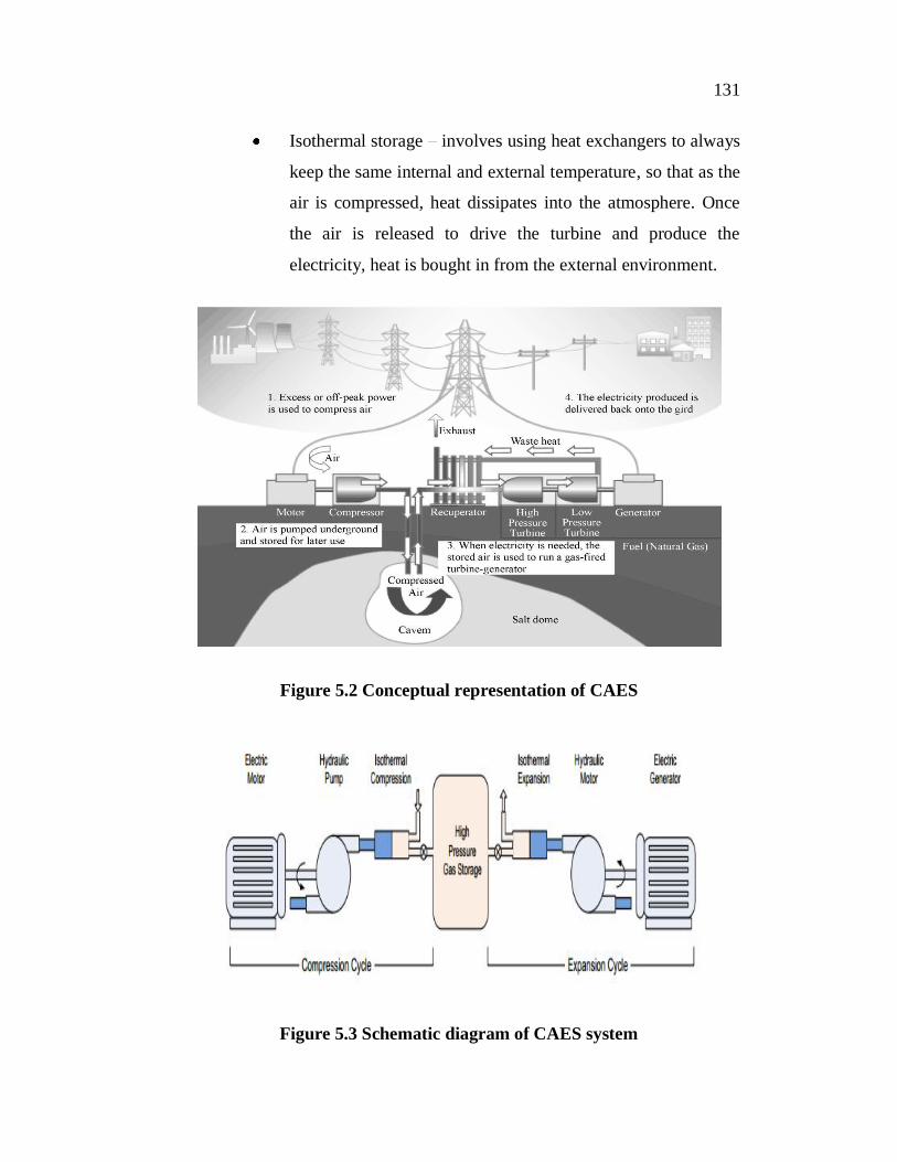
power with a turbo-generator/gas turbine system. The conceptual
representation of CAES and its schematic diagram proposed in Bradshaw
(2000), Swider (2007), Vongmanee & Monyakul (2008) are shown in
Figure 5.2 and Figure 5.3 respectively. Three types of technologies used to
compress the air are given below:
Adiabatic storage - retains the heat of compression and reuses
this when the air is expanded to produce the power expected
efficiency is around 70% (although theoretically 100%
possible)
Diabetic storage takes the heat and dissipates it into the
atmosphere via heat intercoolers. When the air is released
through the turbines it needs to be heated and expected
efficiency is around 70%.
131
Isothermal storage involves using heat exchangers to always
keep the same internal and external temperature, so that as the
air is compressed, heat dissipates into the atmosphere. Once
the air is released to drive the turbine and produce the
electricity, heat is bought in from the external environment.
Figure 5.2 Conceptual representation of CAES
Figure 5.3 Schematic diagram of CAES system

132
5.3 PROCESS OF AIR ENERGY CONVERSION
The energy conversion process of the proposed system consists of
three main components: air compressor, storage vessel/underground salt
cavern and compressed air generator. This process mainly involves
thermodynamic energy conversion process at constant temperature. The
energy conversion starts with the compressor, and the electrical power from
renewable energy is converted into mechanical torque to suck and compress
air from the atmosphere and store in the tank. Then, the compressed air power
is converted back to torque to drive the prime mover coupled with the
generator.
5.3.1 Air Compression/Expansion Process
The air compressor/expander uses mechanical energy from the
rotational shaft to compress air for storage, and extracts energy from the
compressed air through expansion to drive the rotating shaft. The
thermodynamics of air energy conversion for both compression and
expansion are considered as an isothermal process where the temperature is
constant. As ideal gas law, PV = nRT, which relates temperature (T), pressure
(P) and volume (V), is used to derive the power and work. In
thermodynamics, the work involved when a gas changes from initial state to
final state is referred in Equations (5.1) and (5.2).
(5.1)
= (5.2)
where P is the pressure, V is volume, n is the number of mole and R is the gas
constant, W is work done on the system. and are the pressure and
volume of the atmospheric state and compressed air state, respectively.
133
However, power is work per unit time and air flow (Q) is volume per unit
time (Q = V/t). The compression power ( ) is expressed as Equation (5.3).
(5.3)
The compressed air flow driven by electric power can be expressed
by Equation (5.4).
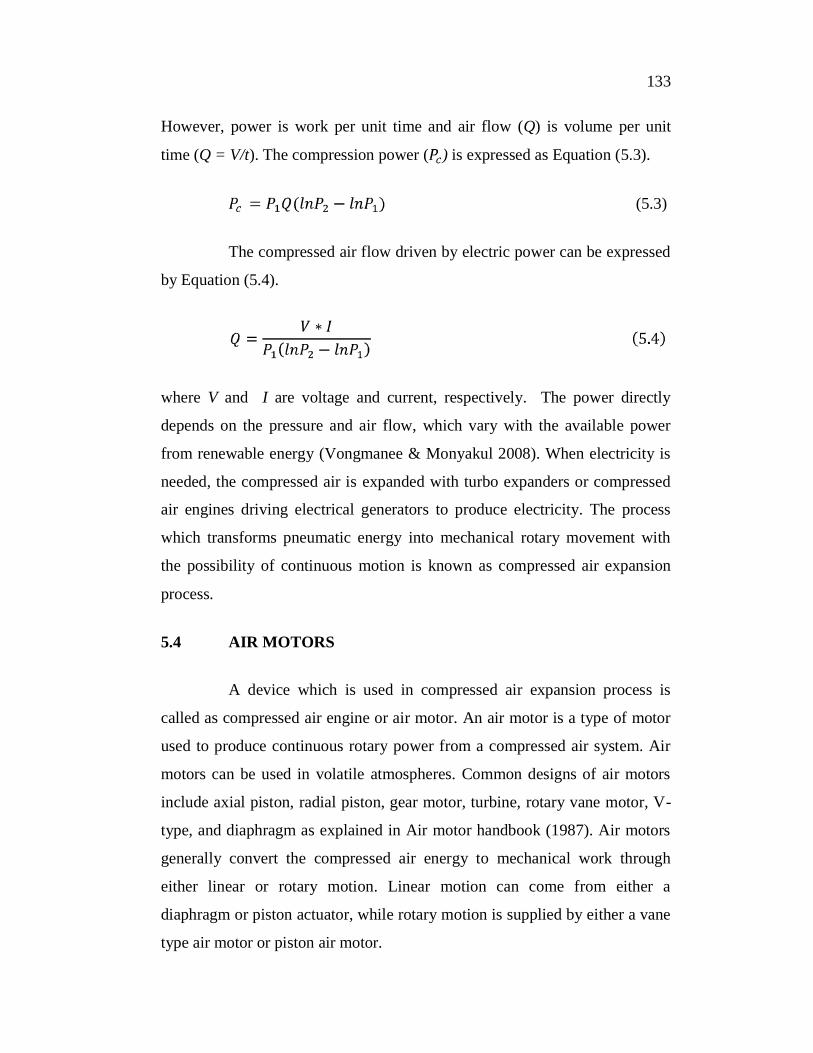
where V and I are voltage and current, respectively. The power directly
depends on the pressure and air flow, which vary with the available power
from renewable energy (Vongmanee & Monyakul 2008). When electricity is
needed, the compressed air is expanded with turbo expanders or compressed
air engines driving electrical generators to produce electricity. The process
which transforms pneumatic energy into mechanical rotary movement with
the possibility of continuous motion is known as compressed air expansion
process.
5.4 AIR MOTORS
A device which is used in compressed air expansion process is
called as compressed air engine or air motor. An air motor is a type of motor
used to produce continuous rotary power from a compressed air system. Air
motors can be used in volatile atmospheres. Common designs of air motors
include axial piston, radial piston, gear motor, turbine, rotary vane motor, V-
type, and diaphragm as explained in Air motor handbook (1987). Air motors
generally convert the compressed air energy to mechanical work through
either linear or rotary motion. Linear motion can come from either a
diaphragm or piston actuator, while rotary motion is supplied by either a vane
type air motor or piston air motor.

134
5.4.1 Piston Motors
Piston motors are most commonly used in hydraulic systems. It is
same as hydraulic pumps except that they are used to convert hydraulic
energy into mechanical energy. To ensure smooth running, it is used in a
series of two, three, four, five, or six cylinders that are enclosed in housing.
This allows for more power to be delivered by the pistons because several
motors are in sync with each other at certain times of their cycle. The power
of the motor depends on the input pressure, number of pistons, piston area,
stroke and piston speed. The force from axially arranged cylinders is
converted into a rotary motion.
5.4.2 Gear Motors
In this design, torque is generated by the pressure of the air against
the teeth profiles of two meshed gear wheels. One of the gear wheels is
secured to the motor shaft. Gear motors are produced with spur or helical
gearing. Gear motors deliver high torque at low speed without additional
gearing. When coupled with a 2-stage orbital planetary gear train, gear motor
power elements provide torque at speeds down to 20 rpm. These motors are
well suited to hazardous-environment applications where relatively high
torque is needed in a limited space. Like vane motors, they are much less
sensitive to mounting orientation than piston motors.
5.4.3 Turbine Motors
The efficiency of an air motor is defined as the ratio of the actual
power output to the theoretical power available from the compressed air for
the expansion ratio at which the machine is operating. Turbines convert
pneumatic power to mechanical power at about 65% to 75% efficiency.
Turbine efficiency is higher than other air motors because the sliding contact

135
of parts does not occur to cause internal friction. Recently turbine technology
is being applied for starting small, medium and large reciprocating engines.
Turbine motors are relatively compact and light, for their power delivery
capability.
5.4.4 Rotary Vane Motors
Rotary vane motors are normally used in applications requiring low
to medium power outputs. Because of their simple construction and low
weight, sliding vane motors are used in a host of mixing, driving, turning, and
pulling applications. Rotary vane air motors are available with three to ten
vanes. There is a rotational drive shaft with four slots, each of which is fitted
with a freely sliding rectangular vane. When the drive shaft starts to rotate,
the vanes tend to slide outward due to centrifugal force and are limited by the
shape of the rotor housing. Depending on the flow direction, this motor will
rotate in either clockwise or counter clockwise directions. The rotor speed is
between 3000 rpm and 8500 rpm and power range is 0.1 kW - 17 kW
(0.14hp - 24 hp). The difference of air pressure provides force on the vanes,
so that the motor can rotate in either direction. Torque is developed from
pressure acting on one side of the vanes. Torque at the output shaft is
proportional to the exposed vane area, the pressure, and the moment arm
through which the pressure acts.
5.5 PROPOSED WORK
The energy conversion process of the proposed system consists of
three main components: air compressor, energy storage vessel and
compressed air generator. The electrical power from the grid is converted
into mechanical torque is applied to suck and compress the air from the
atmosphere and store it in the tank. Then the compressed air transmits the air
power to drive the prime mover coupled to the generator, where the

136
mechanical power is converted back to electric power. The compressed air is
released back into the atmosphere again. The functional block diagram of the
proposed work and the proposed control system are shown in Figure 5.4 and
Figure 5.5 respectively.
Figure 5.4 Functional block diagram of the proposed system
Figure 5.5 Proposed control system
PI Controller
5/3 way Pneumatic
Valve
RotaryVane Motor
Synchronous Generator
Desired Frequency
System Frequency
Control Input to the
valve

137
5.5.1 PI Controller
PI (Proportional-Integral) controllers are commonly used to
regulate the time-domain behaviour of many different types of dynamic
plants. In this work PI controller is designed to control the pneumatic control
valve. The output of the PI controller is used to adjust the valve position of
the 5/3-way pneumatic control valve. PI controller works in the closed-loop
system shown in Figure 5.5. The variable e represents the tracking error, the
difference between the desired frequency (set point) and the actual output
frequency of the generator. This error signal will be sent to the PI controller,
and the controller computes both the proportional and the integral of this error
signal.
The output of the controller is defined in Equation (5.5),
where and are the tuning parameters of PI controller and is the
integral time constant of the system. PI controller signal generation is shown
in Figure 5.6. The controller takes e and compute proportional and integral
gain.

138
Figure 5.6 PI controller signal generation
Though 95% of the industrial controllers are PID type, most loops
are actually PI control. Finding optimum parameters for a PI controller is a
daunting task, so control engineers still use trial and error method for tuning.
PI controller will eliminate forced oscillations and steady state error. PI
controllers are very often used in industry, especially when the speed of the
response is not an issue. The tuning procedure for a PI controller is given
below,
Set integral gain ( ) to zero
Set proportional gain ( ) low for system stability
Apply a step command
Increase to maximum value without overshoot
Increase approximately to 10% overshoot
Adjusting the weighting constants and continuously till the PI
controller is set to give the desired performance (Patranabis 2012). In the

139
proposed work with = 10 and = 20 for PI controller, the desired
response is achieved.
5.5.2 Pneumatic Control Valve
The directional control valves control the passage of air signals.
The 5/3 valve has 5 working parts and 3 switching positions. Directional
control valves with three positions have a mid-position offering additional
options for cylinder actuation. With these valves, double-acting cylinders can
be stopped within the stroke range. This means a cylinder piston under
pressure in mid position is briefly clamped in normally closed position and in
normally open position, the piston become unpressurised. If no signals are
applied at either of the two control ports, the valve remains centered in mid
position. In a 5/3 control valve the positions can either be, pressure is applied,
pressure is exhausted or all 5 ports are blocked. The main reason for the last
position would be to maintain high standards of safety. The flow control
valve restricts or throttles the air in a particular direction to reduce the flow
rate of the air and hence control the signal flow. Ideally, it is possible to
infinitely vary the restrictor from fully open to completely close. The flow
control valve is fitted close to the working element and must be adjusted to
match the requirements of the application (Beater 2007). Figure 5.7 shows the
pneumatic symbol of 5/3-way pneumatic control valve.
Figure 5.7 Pneumatic symbol of 5/3-way pneumatic control valve

140
5.5.3 Pneumatic Vane Motor
Pneumatic actuators convert the compressed air energy to
mechanical energy through motion technology. They can be employed
extensively for simple position and speed control applications in industry.
The schematic diagram of pneumatic vane motor is shown in Figure 5.8.
Figure 5.8 Schematic diagram of pneumatic vane motor
If the storage facility is full of compressed air, the cavern pressure
is higher and if the cavern is almost empty then the cavern pressure is low.
Therefore, there are two operating modes considered for CAES system:
Allow the pressure to change naturally as the air is released,
which will mean that the turbine creates less electricity as
time goes on.
Control the speed at which the air is released from the cavern
to ensure constant electricity supply from the turbine /
generator.

141
The amount of energy produced by the compressed air energy
storage facility is reflected by controlling the source of air driving the turbine.
5.6 SYSTEM SPECIFICATIONS
5.6.1 Generator Specifications
Synchronous Generator
Nominal power = 4 kW
Line to line Voltage = 400 V
Frequency = 50 Hz
5.6.2 Vane Air Motor Specifications
Power = 6.7 hp or 5 kW
Speed = 3000 Rpm
Flow rate = 4.7 m3/min
Pressure = 5 Bar
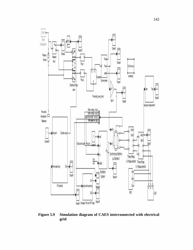
The dynamic performance of the proposed system is assessed
through digital simulation. The MATLAB/Simulink model has been
developed for the proposed work is shown in Figure 5.9.
142
Figure 5.9 Simulation diagram of CAES interconnected with electrical grid

143
5.7 SIMULATION RESULTS AND DISCUSSIONS
During sudden changes in load demand, two case studies have been
considered in order to investigate the dynamic performance of the system to
maintain frequency under variable load. In the first case study, the
stabilization of frequency and the rate of air flow during load variation in grid
connected mode is considered, and in the second case study, the stabilization
of frequency and air flow rate under load variation in island mode of
microgrid is considered. In case 1, the system is initially operated with load
demand which is less than generated power, and in case 2, the system has
more load demand than generated power. The simulation results are studied to
observe the improvement in the behaviour of the power system dynamics due
to variation in load.
5.7.1 Case 1
Figure 5.10 Stabilized frequency response for load variations (Off-Peak load)
In the first case the frequency of oscillations is investigated during
off-peak load period. For this purpose, the load on the system is increased
A t B
added at t = 8 sec. In Figure 5.10, the grid frequency is fluctuating at t = 8 sec
and after few seconds it has been slowly suppressed effectively.
144
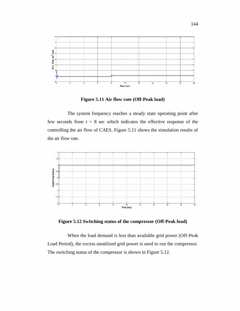
Figure 5.11 Air flow rate (Off-Peak load)
The system frequency reaches a steady state operating point after
few seconds from t = 8 sec which indicates the effective response of the
controlling the air flow of CAES. Figure 5.11 shows the simulation results of
the air flow rate.
Figure 5.12 Switching status of the compressor (Off-Peak load)
When the load demand is less than available grid power (Off-Peak
Load Period), the excess unutilized grid power is used to run the compressor.
The switching status of the compressor is shown in Figure 5.12.
145
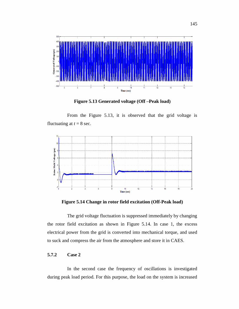
Figure 5.13 Generated voltage (Off Peak load)
From the Figure 5.13, it is observed that the grid voltage is
fluctuating at t = 8 sec.
Figure 5.14 Change in rotor field excitation (Off-Peak load)
The grid voltage fluctuation is suppressed immediately by changing
the rotor field excitation as shown in Figure 5.14. In case 1, the excess
electrical power from the grid is converted into mechanical torque, and used
to suck and compress the air from the atmosphere and store it in CAES.
5.7.2 Case 2
In the second case the frequency of oscillations is investigated
during peak load period. For this purpose, the load on the system is increased

146
A t B
added at t = 8 sec. In Figure 5.15, the grid frequency is fluctuating at
t = 8 sec and after few seconds it has been slowly suppressed effectively. In
this mode total load power is greater than the generated power.
Figure 5.15 Stabilized frequency response for load variations (Peak load)
After few seconds the system frequency reaches a steady state
operating point from t = 8 sec which indicate the effective response of
controlling the air flow of CAES. Figure 5.16 shows the simulation results of
the air flow rate.
Figure 5.16 Air flow rate (Peak load)
147
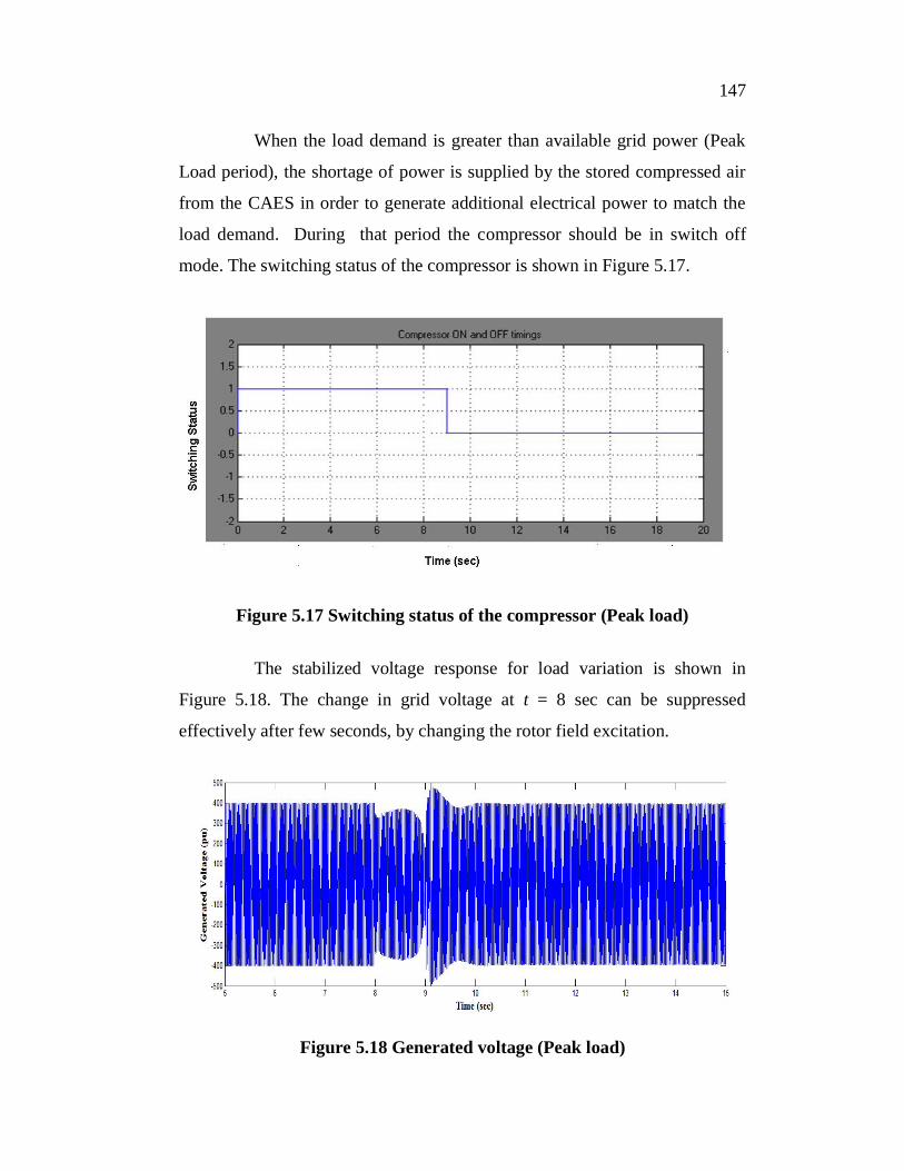
When the load demand is greater than available grid power (Peak
Load period), the shortage of power is supplied by the stored compressed air
from the CAES in order to generate additional electrical power to match the
load demand. During that period the compressor should be in switch off
mode. The switching status of the compressor is shown in Figure 5.17.
Figure 5.17 Switching status of the compressor (Peak load)
The stabilized voltage response for load variation is shown in
Figure 5.18. The change in grid voltage at t = 8 sec can be suppressed
effectively after few seconds, by changing the rotor field excitation.
Figure 5.18 Generated voltage (Peak load)

148
The grid voltage fluctuation is suppressed immediately by changing the rotor field excitation as shown in Figure 5.19. In case 2, the compressed air transmits the air to drive the prime mover of the generator through which the mechanical power is converted back to electric power.
Figure 5.19 Change in rotor field excitation (Peak load)
5.8 SUMMARY
The impact of frequency control of power system combined with microgrid was examined. The complete process is implemented in MATLAB/SIMULINK environment. From the simulation results, it reveals that as the extra power from the air motor output, compensates the power shortfall during load variation. The proposed work improves the frequency stability and demand response by employing CAES. The CAES is used in a power grid to store the excess energy when the energy production is high and the demand is low and utilize the stored energy when the produced energy cannot meet the high demands of the consumers. During sudden load changes the effectiveness of controller to control the air flow from CAES is investigated. The simulation results demonstrated the microgrid with storage system can provide better frequency stability and demand response. The simulation results proved the stability performance of the grid under various load demands and showed the effective use of CAES system to balance the power generation and consumption.