Embed Size (px)
Citation preview

289
CHAPTER-5
MECHANICAL AUXILIARIES SYSTEM 5.1 Mechanical Auxiliary System Equipment General Requirement
The mechanical items of Works of the auxiliary systems including installations generally fulfill the requirements as given below. All components are required to be of reliable design.
Bolts, Screws, Nuts etc.: All bolts, studs, screws, nuts, and washers should be as per ISO metric system. Mild steel bolts and nuts should be of the precision cold forged or hot forged type with machined faces parallel to one another. All bolts and studs which will be subject to high stress and/or temperature should be of high tensile material with nuts of appropriate material.
Fitted bolts should be a driving fit in the reamed holes and should have the screwed portion of a diameter such that it will not be damaged during driving. They should be properly marked in a conspicuous position to ensure correct assembly at site.
All parts (other than structural steel work) bolted together, should be spot faced on the back to ensure that nuts and bolt heads bed down satisfactorily. Mild steel nuts and bolts should be zinc or cadmium plated. Stainless steel bolts, nuts, washers and screws should be used for holding renewable parts in water or when exposed to high humidity. Seals: Rubber seals should be made of synthetic rubber suitable for particular application and should be designed in such a manner that they are adjustable, water tight and readily replaceable. Seals should be manufactured by molding process and not extruded. All adjusting screws and bolts for securing the seals and seal assembly should be of non-corrosive stainless steel. Oils and Lubricants: Different types of oils, lubricants, etc. should be subject to the written approval of the Purchaser. The oil or grease for bearings, pressure oil systems, transformers, etc., including the necessary quantity for flushing and quantity for first oil change with 20% extra should be as per requirement.
Piping, Fittings, Valves and Gates General: All piping is required to be furnished complete with flanges, joints, expansion joints, gaskets, packing, valves, drains, vents, pipe suspensions, supports, etc. Flanged joints or connections should be provided only as required for transport, installation or for dismantling and reassembly. Standard metric flanges and connections are used for all pipe works. Adequate clearance is given to parallel pipes to allow for easy maintenance without disturbing other lines. All overhead piping is required to have a minimum clearance of 2.1 m from operating floors and platforms. All pipes are supported/restrained/anchored in order to prevent any undue localized stress and deflection/sagging anywhere along the piping length due to the applied forces/moments. For the above purpose standard support attachments such as clamps, saddle plates, braces, angles/cleats, guides etc. and support components such as hangers, rods, turn buckles, spring boxes etc. are used. Materials of Pipes & Fittings : Water, air and drain piping less than 25 mm nominal bore are of galvanised heavy grade to IS-1239, Part-I or equivalent standards steel pipe. Pipes equal to or greater than 25 mm nominal bore are galvanized heavy grade to IS-1239, Part I/IS-3589 or equivalent. Oil piping greater than 25 mm nominal bore are of seamless high quality steel pipe conforming to IS 1239 or API-5L GR.B or equivalent grade as per process requirement, whereas pipes less than 25mm bore are of stainless steel.

290
Steel pipes of diameter 100 mm and above for a pressure up to PN 10, are used in welded type. The minimum wall thickness of pipes is the "normal" or "standard" wall thickness as per applicable standards. Pipe Work Fabrication: Steel pipe work smaller than 25 NB and for operating pressure more than PN 10 is joined by screwed fittings and pipe work for 25 NB and over is joined by welded flanges. Pipe work for operating pressure up to PN 10 may be joined by screwed fittings up to 50 NB size. Tag welding is used for fabricating pipe work. Pipe work Cleaning: Oil pipe work internal bores are chemically cleaned and passivated prior to use. Water, air and drain piping as blown through with high pressure air and flushed with water prior to use. Pressure Testing: All pressure piping is pressure tested at a pressure 50% greater than maximum operating pressure after erection and cleaning but before painting at site. The test pressure is maintained without loss for half an hour. Painting: All steel piping is painted on the exterior to prevent rusting. The paint treatment is of the same system as used for the turbine exterior. Colour coding of pipe work is adopted as per applicable Indian Standard. Paint damaged during erection and commissioning is repaired prior to handing-over the plant. Protection for Transport and Storage: Oil piping is required to have a protective coating applied to prevent corrosion occurring during transport and storage. The ends of the pipe lengths should be plugged to prevent ingress of water. Valves & Gates: Generally, valves are required to be leak-proof in either flow direction (except for non-return valves) when the nominal pressure is applied. All valves with design pressures higher than PN 10 and diameters larger than DN 100 are workshop-tested for tightness and soundness of materials. Valves close clockwise and provided with position indicators/marks on hand wheel. The drive units of motor-driven valves are provided with hand wheels for manual operation. To facilitate operation, large valves and gates are provided with by-pass lines for pressure balancing, if required. Valves spindles and pins are of stainless steel, spindle nuts and bushes of bronze, the body of cast steel. No valve in cast iron body is accepted. All pressure reduction valves; safety valves and similar components are workshop-tested. Mechanical Instruments: All mechanical parts of instruments are suitably protected against shocks and vibrations, heat, humidity and splash water, etc. Pressures gauges are provided with a damping liquid, e.g., glycerine, to compensate vibrations. Pressure gauges without damping means are not normally permitted. Pumps: Materials of the main parts of pumps are:
− Casing Cast steel − Impeller stainless steel − Shaft stainless steel − Sleeves stainless steel − Wear rings bronze − Keys stainless steel
The capacity of the driving electric motor is 15 % higher than the maximum power required by the pump at any operation point The overall pump-motor efficiency for the specified rated head and discharge is specified to be not less than 60%. The pumps are required to withstand corrosion and wear by abrasive matters within reasonable limits. Shafts sealed by packing glands are fitted with sleeves. Pump seals are replaceable without extensive dismantling of the pump. Leakage water is directed to suitable drainage facilities.

291
Miscellaneous Metalwork Normally following are included in the equipment supplied. • All platforms, ladders, guards, handrails of tubular construction and hatch covers necessary for easy
and safe access to Works.
• Safety guards at each point where normal access provision would permit personnel to come within reach of any moving equipment.
• All covers for pipe work, cable trenches and access hatches, required for completing the floors around and over the equipment are supplied and installed. Unless otherwise approved, floor chequered plates are required to be of an angular pattern.
5.2 E.O.T. CRANE
Cranes are used in the power house for operational function and for maintenance and repair. Power house bridge crane (electrical over head traveling crane EOT) is the principal overhead traveling crane for turbines, generators and auxiliaries in typical medium and large power house. The crane comprises of main hoist consisting of one or more cranes with combined capacity to lift the heaviest assembly of the generating units. An auxiliary hoist of much lower capacity is provided for handling smaller parts. Number of Cranes: The choice of providing one or two cranes with a lifting beam is an important consideration in power house because of following reasons especially in power house with large number of units (generally 5 units or more).
i) power house structural costs
ii) construction and erection advantage
iii) 2 cranes with lifting beam will need additional crane clearance and increase in height of power house.
iv) Value of down time
In Bhakra Left Bank 2 cranes with lifting beam was provided. In small hydro stations only one crane is sufficient. Crane Capacity: Crane capacity in Hydro Power Stations is based conventionally on estimated load -weight of the heaviest part to be lifted with about 25% overload capacity. The rated load capacity of the main hoist should be capable of lifting the heaviest assembly specified and not less than weight of the generator rotor assembly including poles, shaft and turbine runner.
Standard: IS: 3177 – 1999 –Code of practice for Electrical Overhead Traveling Cranes and Gantry Cranes
IS: 807 – Structural design of crane
For small powerhouses, manual monorail hoist may be used. In micro hydro range EOT crane is not provided. Erection may be done by chain pulley block, mobile crane or manually.
5.2.1 Typical EOT Cranes Specifications
Typical EOT Cranes Specification for a power house (one crane) for medium range turbine generators is given below.

292
Scope of Supply
• One (1) Power House say 60/10T (approx.) EOT crane complete with Bridge, Operator's Cab, Trolley, Main Hoist, Electrical Controls, safety devices, fittings & connections and all necessary accessories to handle equipments.
• One (1) cradle, slings, etc. for load testing at site.
• One (1) set of main run way rails with base plates, anchor bolts, rail clips, lock nuts end, stops, limit switches, striker plates, etc. for Power House & Butterfly valve cavern (Valve House) if provided.
• One (1) set main run away conductors complete with brackets, fittings, inter connecting wiring etc. for Power House & Valve House.
• All special tools, devices, spanners etc. for assembly and installation of cranes.
• Wire ropes, for main hoists and Auxiliary hoists of cranes.
• One (1) set of spares for 5 years of normal operation of cranes.
• Any other items not specified above but necessary for proper operation of cranes.
Design Requirements All parts of the crane and runway rails should be designed to sustain the loads and the combination of loads listed below with due allowances for eccentricity of loading without exceeding safe permissible stresses. Mechanical parts of the crane including trucks and trolley frames should be designed for the specific loads using a factor of safety of 5 (Five) based on the ultimate strength. a) Loads:
i. Dead load: The weight of all effective parts of the bridge structure, machinery parts and fixed equipment supported by the structure.
ii. Live load: The weight of trolley and lifted load (rated capacity) considered as concentrated moving loads at wheels in such positions as to produce the maximum moment and shear.
iii. Vertical impact load: 15 (Fifteen) per cent of the total live load.
iv. Braking load: The force produced on sudden application of bridge travel brakes when carrying rated load and traveling at full speed with the power off.
v. Lateral load due to trolley tractive effort: 10 (Ten) per cent of the sum of trolley weight and the rated crane capacity applied equally on the trolley rails.
vi. Longitudinal load due to bridge tractive effort: 10 (Ten) per cent of the sum of the weight of crane and its rated capacity with the lifted load located at the extreme extent of travel of each end of bridge.
vii. Earthquake load: Earthquake force to be taken equivalent to 0.3 g in horizontal direction and 0.14 g in vertical direction (depends on earthquake zone).
viii. Other loads: Such as design floor load, special design load for horizontal frame design.
b) Combination of loads: Unless otherwise stated, the crane should be designed to sustain the combination of loads listed below without exceeding the safe permissible stresses.
i. For crane in static hoisting position with dead load, live load and vertical impact load.
ii. For crane in motion with dead load, live load, and any one horizontal load listed under lateral, longitudinal or specific design loads.
iii. For crane in motion with a combination of dead load and braking load.
iv. For crane in static position with dead load plus earthquake load.

293
v. For crane in motion with dead load, live load and any 2 (two) or more horizontal loads listed under lateral longitudinal or special design loads with resulting unit stresses not more than 33-1/2 (Thirty three and one half) per cent in excess of safe stress.
vi. For crane in static hoisting condition, with a combination of load and forces produced by the maximum or breakdown torque of the main hoist motor with resulting stresses not exceeding 90 (Ninety) per cent of the elastic limit of materials concerned.
Performance Requirements
The crane is required to be capable of raising, lowering, holding and transporting its rated load without any damage or excessive deflection of any crane component. The following tolerances are maintained in the operation of the crane. a) Smooth control of vertical movement to within 3 mm with hook carrying rated load and all hoist
brakes properly adjusted at normal operation.
b) Control of bridge and trolley motions to within 6 mm.
c) The motor speed not to exceed 105 (One hundred and five) percent of synchronous speed while lowering a rated load.
d) The vertical deflection of crane girders caused by the rated load plus all dead loads not to exceed 1/1000 of the crane span.
5.3 COOLING WATER SYSTEM
Cooling water system may be required in a powerhouse for the following.
i) Generator air coolers and bearing coolers.
ii) Turbine bearing coolers, wearing rings and gland. Turbine glands and wearing
ring require water of suitable quality.
iii) Transformer cooling 5.3.1 Water Requirements:
(i) The water flow requirements are determined by generator and turbine suppliers but are dependent on water supply temperature and should take into account extremes in climate conditions for the site. Flow requirements are usually large and require dependable sources. Purity requirements are moderate permitting non potable supplies with limited silt content.
ii) Gland and wearing ring requirements are obtained from turbine supplier. Quality requirements are nominal requiring the removal of abrasive material.
iii) Transformer Cooling: Most plant in the SHP range utilize air cooled transformer. Large generator transformers are generally water cooled. Quality and quantity requirements are same as for generator cooling water.
5.3.2 Sources
(1) Spiral Case – For units with heads up to about 75 m, the preferred source of cooling water is a gravity supply from an inlet in the spiral case or spiral case extension. In multiunit plants, an inlet is provided for each unit with a common header connecting all units to provide a backup water supply to any one unit. Cross-overs between pairs of units only are not regarded as adequate since there would be no emergency source from an un watered unit. The spiral case source is usually satisfactory for unit bearing coolers, as well as the generator air coolers, and can be adequate for gland and wearing ring use with proper filtering and adequate head.
294
(2) Tail race water – For higher head projects, above 76 m, the usual source of cooling water is a pumped supply from tail race water. This normally provides water of essentially the same quality as the spiral case gravity system.
In small units the bearing and gland cooling water supply from raw water has caused problems of abrasion/choking especially in Himalayan region. Special treatment of raw water to remove silt or even supply of cooling water from specially bored tube well supply has been provided.
(3) Other sources – It is unlikely that other suitable sources will be available or required for cooling requirements, but alternate sources should be considered for gland requirements. Silt or other abrasive material is usually present in varying degrees in reservoir water, at least seasonally, and since abrasive material is injurious to glands, an alternate source or additional treatment is usually required. The potable water system is normally the best alternate if the supply is adequate or could be economically increased. This would usually be in the case of a tube well supply requiring little chlorination. Where potable water is used, cross connections from the cooling water source, with backflow protection, should be provided for emergency use.
5.3.3 Head requirements
Normally the cooling water supply should provide a minimum of 68.9-kPa differential across the connection to the individual cooler headers. Available gravity head, cost of a pumped supply, and cost of coolers all enter into an optimum cooler differential requirement and require early design consideration to assure a reasonable figure for the generator and turbine specification. Gland and wearing ring differential head requirements should be obtained from the turbine supplier.
5.3.4 Treatment
Water for coolers, glands, and wearing rings will normally require only straining or filtration. This should be verified from operating experience at nearby existing plants on the same stream. Where existing plants are remote or the project is on a previously undeveloped stream, a water analysis should be the basis of determining the likelihood of corrosion or scale deposits and the need of additional treatment. Typical strainer requirements for coolers permit 3-mm perforations, but strainer specifications for existing projects should be obtained as a guide to complete design requirements. Strainers should be the automatic type unless the system provides other backup provisions for continuous water supply or the p. h. is small. Unnecessarily fine strainers requiring more frequent servicing should be avoided. Filters are required for gland water unless the supply is the potable water system. The system should provide for continuous operation when an individual filter requires cleaning.
5.3.5 Pumps
A pumped cooling water supply requires a standby supply for a pump out of service. This can be provided with two pumps per unit, each of which is capable of supplying cooler requirements, or one pump per unit and back up consisting of a common pump discharge header to all units and one or more backup pumps. Other arrangements to provide backup capacity may also be acceptable. Pumps should be located such that flooded suctions occur at minimum tail race water. Continuously rising pump performance curves are required, and the pump speed does not exceed 1,500 rpm.
5.3.6 Piping
i ) Design considerations for piping include, velocity, pressure loss, pumping costs, corrosion allowance, equipment connection sizes and requirement, mechanical strength, temperature, expansion etc. .
ii) Water takeoffs from the spiral case or the spiral case extension should be within 30 deg of horizontal center line to minimize debris and air.
iii) A valve should be located as close to the casing as practicable for emergency shutoff.
iv) Balancing valves should be located in cooler supply lines.

295
v) A removable 0.9-m section of straight pipe should be provided in the generator bearing supply line for temporary installation of a flow meter.
5.3.7 Typical Cooling Water Systems Specification for a low head canal fall power house with Kaplan turbine driven bulb generators is given below.
Scope of Supply
Tapping arrangement from intake - 2 sets
Pump Motor Sets - 3 sets Motorised self cleaning strainer - 3 sets
Servo operated hydro valve with solenoids - 2 sets Necessary valves, pipes, supports etc. - 1 lot General Design and Constructional Requirements
i) Cooling water system should be common for both the units. Cooling water will be tapped from intake upstream of the bulbs of both turbines through embedded pipes and connected to a common header through isolating valves. Three pump motor sets (two mains, one for each unit and one standby) should be used to supply adequate cooling water to generator air coolers and guide bearings of the units. The system should provide 100 % redundancy operation of the unit pumps. Cooling water requirement of one unit should be met by one pump. The third pump should be used as standby pump for both units. Cooling water after passing through strainers will be fed to a common header and distributed to each unit.
ii) The C.W. system will be installed at EL 238.000 and water after passing through heat exchangers should
be discharged into tail race at EL 239.000, above maximum TWL. iii) The pumps should be centrifugal type directly driven by 3 phase 415VAC squirrel cage induction
motors. The pump motor should be mounted on common base plate. The impeller of pumps will be made in stainless steel, pump casing in steel casting and shaft in stainless steel. The discharge capacity of each pumps should meet the total requirement of cooling water of one unit.
iv) Motorized self cleaning strainer with discharge capacity 1 ½ times the pump discharge should be
provided after each pump to supply silt free clean water to various cooling circuits. The strainers should be cleared off accumulated silt automatically through a motorised rotating arm mechanism. Cleaning operation will be operable through pressure differential switch and timers.
v) Servo operated hydro valve controlled by 110 VDC (or as available) solenoids or motor operated valve
should be provided on feeding line of each unit to control cooling water supply during starting/shut down of units.
vi) Control of the pumps should be built in Unit Control Panels and their starter panels will be located near
the pumps. vii) Valves, Pipes and Fittings: All gate valves and non-return valves should have housing in steel casting
and valve seat in stainless steel. Piping should be complete with sufficient number of bends, elbows, tees, clamps, flanges and fasteners.
5.4 DEWATERING AND DRAINAGE SYSTEM 5.4.1 General
The Dewatering system provides the means for dewatering main unit turbines and their associated water passages for inspection and maintenance purposes. Drainage system provides for the collection and disposal of all powerhouse leakage and wastewater other than sanitary. The safety of personnel and plant is of vital concern in this system and should have continuing priority throughout the design. It may be noted

296
that following type of turbine will not require dewatering arrangement because they are set above maximum tail water level and can be accessed without dewatering.
a) Impulse turbine b) Vertical Kaplan/Francis turbine with siphon intake
5.4.2 Dewatering System
General The principal volumes to be dewatered in all powerhouses are the spiral case and draft tube. In addition, there is usually a considerable volume downstream of the headgates or the penstock valve. Dewatering Procedure Normal procedure after unit shutdown requires: closing of the headgates or penstock valve; drainage of all unit water above tail race water to tail race water elevation through the drain; and spiral case or spiral case extension drain; placement of draft tube gates or stoplogs; and draining the remaining unit water to sump with the sump pumps operating.
Dewatering Time Aside from safety, the required elapsed time for completing a unit dewatering is the major factor in dewatering system design. Unit downtime will usually be of a value justifying facilities to perform dewatering in 4 hr. or less. This can mean that in a typical plant all necessary valve, gate, and stoplog or gate operations should be done in approximately 1 hr and draining of the pumping system in approximately 3 hr. Dewatering Sumps Sump provision in most projects require either joint usage in both the dewatering and drainage systems, or separate sumps with the dewatering sump serving as a backup or overflow for the drainage sump. Sumps should be designed for maximum tail race water head. Dewatering Pumps Two dewatering pumps should be provided. Dewatering pump capacity should permit unwatering in 3 hr or less of pumping time with total capacity divided in two pumps of the same capacity. Either pump used alone should be capable of accomplishing the dewatering. Since unit dewatering will not be scheduled under powerhouse design flood conditions, rated dewatering pump discharge should be for a maximum planned tail race water under which dewatering will occur. Pumps of the deep well water lubricated type are normally used. Submersible motor and pump combinations units mounted on guide rails permitting the pump units to be raised or lowered by the powerhouse crane have also been used. Generally float-type controls are used for pump control. Automatic lead-lag with manual selection of the lead pump is provided for uniform wear on both pump sets.
5.4.3 Drainage System
The drainage system handles three general types of drainage as follows: rain and snow water from roofs and decks, leakage through structural cracks and contraction joints, and wastewater from equipment. Discharge is to tail race water either by gravity or by pumping from a drainage sump. Roof and Deck drainage should normally be directly to tail race water by gravity. Drainage of water sprinkler fire protection system if used should be included in the drainage system in the design. In small hydro up to 3000 kW capacity gravity drainage is generally provided.
Float Drainage: Drainage galleries should be provided for float drainage and conduits and pipes connecting the trenches to the drainage sump should be provided. Oil Storage or Purifier Rooms: Oil Storage or Purifier Rooms provided with water sprinkler fire protection system should have chilling drain with a gravel pocket of sufficient capacity to handle the sprinkling system flow. Battery Room: Battery room floor and sink drains should be of acid resisting material, have a minimum 2% slope.

297
Miscellaneous Area Floor Drains: Miscellaneous floor areas i.e. turbine room, galleries, machine shop, toilet rooms etc. where leakage rainwater water from disassembly, flushing, etc. is normally expected should have floors with continuous slope to the drain location. Any drains that come from a source that can add oil to the water should not drain directly to tail race water but should first be routed to an oil separator facility. Pressure wastewater: wastewater from generator air coolers and bearing coolers etc. are normally piped directly to the tailrace. Some powerhouses also require pressure drains for transformer cooling water and air conditioning cooling water. Drainage Piping: Drainage piping design considerations should be based on relevant standards. Drainage Sump: The drainage sump or joint unwatering- drainage sump should be located low enough to provide gravity flow from all drained areas under all dry powerhouse design tail race water conditions and up to the float-operated alarm, sump water elevation.
5.4.4 Typical Drainage and Dewatering Systems Specification for a power house with low head turbines is
given below. Scope of Supply
• Vertical Turbine Pumps for dewatering - 2 sets (Capacity 600 m3/hr.) • Level Controller for dewatering pit. - 1 set • Vertical Turbine Pumps for Drainage - 2 sets ( Capacity 150 m3/hr ) • Level controller for drainage pit. - 1 set • Pipes, valves & fittings. - 1 lot • Special tools and devices for assembly / dismantling of pumps Submersible type pump-motor sets of reliable make may be offered as alternative in place of Vertical
Turbine pumps. General Design & Constructional Requirements
i) Dewatering System
For dewatering the underwater parts, there should be a sump whose bottom elevation will be sufficiently lower than the lowest point of the draft tube where the drain box is fitted to permit flow of water by gravity to the sump by opening a long spindle type gate valve provided at the sump. The dewatering will be done first by allowing the water in the intake & the bulb to flow into the tailrace through wicket gates till the water in the intake reaches the tail water level and then by opening the drain valve in the sump for draft tube dewatering after closing the draft tube gate. The dewatering sump should be provided one sealed cover and covered man-hole. The covers, pump base and level sensor’s base, should be designed to withstand full tail race water pressure. Dewatering system should consist of two numbers vertical turbine pumps (one main & one standby), one set of level controllers, pipe lines and valves. Each pump should be capable of dewatering the turbine in 4-5 hrs. Level controllers should be provided in the dewatering sump to start/stop the pumps automatically & to give alarm at a preset level. Leakage of water from intake & D.T. gates may be assumed as 0.15% of rated discharge of turbine. Both the pumps should discharge into a common discharge pipe after the gate valves and non-return valves. Suitable wall mounted control panel with starter, etc., should be supplied.
ii) Drainage System A separate drainage sump will be made available so as to permit drainage of water by gravity into this sump. The water from the drainage sump should be discharged into the tailrace above the maximum tailrace water level. Both the dewatering and drainage sumps should be inter-connected through a gate valve and non-return

298
valve to allow rising water in the drainage sump to be drained into the dewatering sump on failure of both drainage pumps to cope with station drainage water. The drainage system (common for Power house) should consist of two vertical turbine pumps (one main & one stand by), one set of level controllers, pipe lines and valves. The pumps should be of adequate capacity to remove normal seepage & drainage water but not less than 150 cu.m/hr. The electric motor, pipes & valves should be suitable for the pump rating. Automatic control of the pumps should be arranged through level electrodes. Provision for manual operation should be made on the control panel. The dewatering & drainage pumps and level sensors should be installed at EL 238.000 and the water should be discharged into tail race at EL 239.000, above maximum TWL. Control of the pumps should be built in Unit Control Panels and their starter panels will be located near the pumps.
iii) Pump – Motor Sets The impellors of pumps should be manufactured from stainless steel and the casing of impellor from steel casting. The pump casing and impellors should be provided with removable type of stainless steel liners. The shaft should be of alloy steel with stainless steel sleeves where it passes through bushes. The electric motors should be squirrel cage induction motors with hollow shaft and ratchet arrangement to prevent reverse rotation. The enclosure of the motors should be drip proof type.
iv) Valves, Pipes and Fittings All gate valves and non-return valves should have housing in steel casting and valve seat in stainless steel.
Piping should be complete with sufficient number of bends, elbows, tees, clamps, flanges and fasteners. 5.5 COMPRESSED AIR SYSTEM
Compressed air system is required in powerhouse for operation and to facilitate maintenance and repair. Service air, brake air and governor air comprises the three systems needed in all powerhouses. Reliability, flexibility and safety are prime design considerations. This system is generally not provided for small and micro hydro sets.
Standards
a) IS: 2825 – Code for Unfired Pressure Vessel b) IS: 14642 – Compressed Air for General Use c) IS: 7938 – Compressed Air Installation, Air Receivers d) IS: 4138 – Compressed Air, Safety Code for Working
5.5.1 Brake Air System
a. General: The brake air system comprises one or more semi-independent storage and distribution installation for providing a reliable supply of air to actuate the generator braking systems. Air is supplied from the service air system, stored in receivers, and distributed through the governor actuator cabinets to the generator brake systems.
b. Air Requirement. Air is required in the system to stop all generator-turbine units simultaneously without adding air to the system and without reducing system pressure below 520kPa (5.27 kg/cm2). Storage capacity and pressure depends upon number of brake applications per stop, brake cylinder capacity and volume required for piping and verified by generator manufacturer.
c. Piping-Receivers. Each subsystem includes a receiver, piping from the service air system to the receiver, piping from the receiver to the governor cabinets, and piping from each governor cabinet to the respective generator brake system normally.
d. Control. Control for application of the brakes is normally included in the governor cabinets and provided by the governor supplier.

299
e. In small hydro generator breaking if provided is generally with hydraulic system.
5.5.2 Governor Air System
a. General. The governor air system provides the air cushion in the governor pressure tanks. When the governor system is to be placed in operation, the pressure tank is filled approximately one-fourth full with oil, and the tank is then pressurized to governor-operating pressure from the governor air system. Corrections to maintain the proper oil-air ratio are required at intervals during plant operation. The governor pressure tank size and operating pressure will be determined by the turbine servomotor volume.
b. Air requirements. i) Quantity: Compressor delivery should be sufficient to effect a complete pressurization of a governor tank with the proper oil level in 4-6 hr. ii) System Pressure. The operating pressure should be approximately 10% above the rated governor system pressure. iii) Compressor. The total air-delivery requirement should be provided by two identical compressor, each rated at not less than 50% of the requirement. Compressor should be heavy duty, reciprocating, water or air cooled, and rated for continuous duty.
c. In SHP air pressure vessel for governors is replaced by high pressure oil system with Nitrogen Cylinders.
5.5.3 Depressing Water in Turbine Casing Depressing tail race water by injecting air below runner crown may be required under following conditions. a) Motoring the unit for use as synchronous condenser b) To avoid rough operation at part loads in variable head Francis turbine operating at part gates as in
Bhakra Left bank Power palnt.
5.5.4 Service Air System
(a) General. The service air system is about 700-kPa (7 kg/cm2) system providing air for maintenance and repair, control air, hydro pneumatic tank air, charging air for the brake air system, and in cases, air for ice control bubblers is required (at very high altitudes).
(b) Service Air Requirement. i) Routine Maintenance. Supply 1.5 to 2 m3/minute (m) for wrenches, grinders, hammers, winches, drills, vibrators, cleaning, unplugging intakes and lines, etc. ii) Major Maintenance and Repair. Supply for sandblasting, painting, cleaning etc. is provided with portable equipment. For projects too remote from a government or commercial source of temporary portable equipment, installed capacity be provided (8 m3/m). iii) Ice Control Bubblers. This may be required for hydro plants located very high altitude ice prone areas. iv) Operational Requirements. Supply 7-12 L/s (0.4 to 0.7 m3/sec) with individual assumption as follows:
• Brake system charging air 1-2 L/s • Hydro pneumatic tank 3-5 L/s • Control Bubbler (if required) 1-3 L/s • Leakage 1-3 L/s
v) Standard Provision Basis. It is found that the computed basis will usually require several arbitrary
assumption and service factors to arrive at a total service air requirement. in lieu of the compound basis, the following standard provisions may be used as the basis of total air requirement:
• 1 – 2 unit plants 1.5 m3/min • 3 - 4 unit plants 2 m3/min • Over 4 unit plants 2.5 m3/min
In addition, provide 10 m3/m for major maintenance and repair in mega/remote large plants. If this is supplied with portable equipment, than only ice control bubbler requirement may be provided if required.

300
v) Service Air Pressure. A nominal 700-kPa (7 kg/cm2) pressure with system variations from 580-760 kPa (6 to 8 kg/cm2) is satisfactory.
(c) Compressors. Compressors should be heavy duty, water cooled, flood lubricated, and cooled
rotary screw type rated for continuous duty. Normally, aside from major maintenance, service air should be supplied by two identical compressors each of which is capable of supplying approximately 75% of the requirement. Installed major maintenance and repair capacity is provided with a single compressor.
(d) Receivers. Each air receiver should conform to design construction, and testing requirements of the ASME, “Boiler and pressure Vessel Code.” Receiver capacity should provide a minimum 5 min-running time with no air being used from the system for the largest connected compressor on automatic start-stop control. One or more receivers may be used for the system. However, galvanized receivers are preferred, and sizes should be checked against galvanizing plant capabilities.
(e) Controls. The two service air compressors should each be provided with selective manual or automatic control. They should have pressure switch lead-lag control automatic selection and conventional load- lag control automatic selection and conventional load-unload operation for manual selection. A major maintenance compressor or a separate ice control bubbler compressor (if required) should be on manual control with conventional load-unload provisions. Cooling water should be controlled to flow only when the compressor motor is energized. Automatic shutdown should be provided for low oil pressure, low oil level, and high-discharge air temperature.
5.5.4 Typical Compressed Air System Specification for a medium/large power house is given below.
Scope of Supply
Compressed Air System for Governor O.P.U., Generator Braking and service air shall consist of: • 3 Stage Reciprocating Compressors, 2 m3/minute - 2 nos. • Moisture Separators - 2 nos. • High Pressure Air receiver 1.5 m3 capacity - 1 no • Low Pressure Air receiver 1m3 (for Generator Brakes) - 1 no. • Pipes, valves, instruments & fittings. - 1 lot
General Design and Constructional Requirements: i) Compressed Air System shall be common for both the units. Two reciprocating multistage
compressors driven by electric motors shall be provided to feed compressed air in the air receiver.. One of the compressors shall work as main and other as standby. Their operation shall be made automatic with the help of pressure switches. Compressed air after passing through air dryers shall be fed to one high pressure air receiver. One low pressure air receiver shall be provided for generator brakes. Compressed air from high pressure air receiver shall be tapped and fed to low pressure air receiver through one pressure reducer.
ii) Pressure rating of each compressor shall match maximum pressure requirement of oil pressure unit and generator brakes. The supplier shall check air requirement of the system and provide higher capacity, if required keeping compressor duty cycle in view. Design calculation regarding compressor capacity and strength calculation of air receivers shall be submitted for approval of the Purchaser.
iii) The compressors will be driven by 3 phase, 415 VAC completely enclosed, fan cooled, squirrel cage induction motors with class F insulation through belt drive. Compressor and motor shall be mounted on a common base plate which shall be installed on floor with the help of foundation bolts.

301
iv) Indian Standard IS 2825 shall be followed for design, manufacture and testing the air receivers.
v) The motor starter panel housing contactors, switch fuse units and meters etc shall be mounted on the wall near the compressors and wired complete with leads labeled. The connections to each motor shall be arranged so that either compressor may be removed for repair or replacement without interfering with the continuous operation of the other.
vi) System design shall be subject to approval of the Purchaser.
Shop Tests
The shop tests on compressed air system shall include:
i) Dielectrics and insulation tests on all electric motors,
ii) Routine operational tests including starting current, output torque Vs current characteristics, noise, vibrations on electric motors as per Indian Standard or International standard,
iii) Operational tests and tests for verification of Performance Characteristics of compressors as per Indian Standard/ International standard. Compressors will be tested with their respective motors.
iv) Hydrotatic pressure tests on air receivers at 1.5 times the rate pressure.
v) Hydrotatic and leakage tests on all valves at 1.5 times the rated pressure.
vi) Operational tests on pressure reducer. Field Tests
Following testes will be carried out at site after installation: i) Dielectrics and insulation tests on all electric motors,
ii) Operational tests on compressors for minimum 8 hrs continuous operation to establish trouble free operation without abnormal vibrations and noise,
iii) Operational tests on control panels and instruments. Drawings and Data Following drawings and data shall be supplied with offer: i) Schematic drawing,
ii) Typical General Arrangement Drawing of compressor set,
iii) Typical General Arrangement Drawing of pressure receivers,
iv) Catalogues of compressor, moisture separator and pressure reducer.
v) Electrical Drawing of Control Panel. Following drawings and data shall be supplied after placement of order: i) Schematic drawing,
ii) General Layout drawing of compressed air system showing details of pipes and fittings and installation details of compressors,
iii) General Arrangement Drawing of compressor set,
iv) General Arrangement Drawing of pressure receivers,
302
v) Catalogues of compressor, moisture separator and pressure reducer
vi) Electrical Drawing of Control Panel,
5.6 FIRE PROTECTION SYSTEM 5.6.1 General
Arrangement of fire protection in hydro power station and switchyard is normally divided into following three groups.
i) Fire protection for generators
ii) Fire protection for generator transformers and other equipment in outdoor switchyard
iii) Fire protection of area and equipment in power house not covered under above two groups. 5.6.2 Codes & Standard
i) IS: 1646 – Code of Practice for Fire Safety of Building (General) Electrical Installation
ii) IS: 2189 – Code of Practice – Selection, Installation and Maintenance of Automatic Fire Detection and Alarm System
iii) IS: 3844 – Code of Practice for installation and Maintenance of Internal Fire Hydrants and hose reels on Premises
iv) CBI & P Manual on Transformer
iv) IS: 6382 – Code of Practice for Design and Installation of fixed Carbon Dioxide Fire Extinguishing System
v) IS: 2190 - Code of practice for selection, Installation and maintenance of portable first-aid fire extinguishers
5.6.3 General Consideration for Design of Fire protection System In view of a large number of oil-filled equipments in a Generating Station including outdoor switchyard, it
is very important that proper attention is given to isolation, limitation and extinguishing of fire so as to avoid damage to costly equipment, reduce chances of serious dislocation of power supply and ensure safety of personnel. The first step in this direction is inherent in the design and layout of the powerhouse and substation itself, which should be such that if fire occurs in any equipment it should be limited and isolated so that it does not spread to other equipments. For this purpose the following are the general guidelines:
i) The spacing of the equipment should be considered. Extra space is not usually provided for fire
isolation, but the space available is taken into account in deciding other isolation measures.
ii) Fire isolation walls should be provided between large oil-filled equipments such as two or more transformers placed adjacent to each other. These should be of adequate strength and of such size that the adjacent equipment is reasonably safe from the risk due to burning oil flying from the equipment on fire.
iii) In indoor areas automatic fireproof doors should be provided for rooms which house major oil filled equipment. The rooms should also be constructed with a view to isolating the fire.
iv) Soak pits or drain pits should be provided below large oil-filed equipment to drain off the burning oil falling below the equipment.
v) Minor items of oil filled equipment should be placed in beds of gravel or pebbles which will quench and prevent the spread of burning oil.

303
vi) Care should be exercised that any prospective fire can be easily approached for quenching. In closed spaces and buildings attention should also be given to evacuation of personnel. (Refer IS: 1646).
vii) All oil pipes and cable trenches should be sectionalized by means of cross walls. A well coordinated system of fire protection should be provided to cover all areas of the power house and substation and all types of likely fires. The details of fire protection have to be worked out on the basis of size, type and location of the generating station, accessibility and degree of attendance. Care should be taken and any fire can be fought from more than one source and dependence is not placed on single equipment for this purpose. The subject of fire safety involving electrical equipment is exhaustively covered in latest code and practice mentioned in 5.6.2.
5.6.4 Fire Fighting System in Generating Station
All generating stations should be equipped with fire fighting systems conforming to the requirements given in latest IS: 1646 and fire protection manual Part-I issued by Tariff Committee (TAC) of Insurance Companies.
Trailer pumps where provided should draw their water supply from ground tanks/ tail race water of suitable sizes, the location and distribution of which shall be such that no item to be protected is more than about 90 m away from any ground tank.
The more valuable equipment or areas forming concentrated fire risk should be covered by special fire protective systems. In this class are:
i) Generators ii) Transformers, both indoor and outdoor: iii) Oil filled switchgear iv) Oil tanks and oil pumps v) Oil, grease and paint stores
Although the substitution of bulk-oil and minimum oil circuit breakers by SF6 gas circuit breakers has reduced the risk of fires in electrical installations, considerable risk still exists on account of transformers, cables etc., which contain combustible insulating materials. Fires in live electrical equipment, motors, machinery etc. fall in class C according to the tariff Advisory Committee Classification of Fires. It is necessary to provide efficient Fire Protection Systems in the electrical installations. Fire protection system consists of the following;
i) Fire prevention ii) Fire Detection and annunciation iii) Fire extinguishing
5.6.5 Fire Prevention
Fire prevention is of utmost importance and should be given its due if risk of occurrence of fires has to be eliminated/minimized. The safety and preventive measures applicable for hydro generating stations and substation as recommended by the relevant authorities must be strictly followed while planning. All firefighting equipment and systems should be properly maintained. Regular mock drills should be conducted and generating station staff made aware of importance of fire prevention and imparted training in proper use of the firefighting equipment provided in various parts of the powerhouse, control room building etc.
304
5.6.6 Fire Detection and Annunciation Fire detection if carried out at the incipient stage can help in timely containment and extinguishing of fire
speedily. Detection can either be done visually by the personnel present in vicinity of the site of occurrence or automatically with the use of detectors operating on the principles of fixed temperature, resistance variation, differential thermal expansion, rate of rise of temperature, presence of smoke, gas, flame etc. Fire detectors of the following types are normally used:
(i) Ionization type
(ii) Smoke type (iii) Photoelectric type (iv) Bimetal type (v) Linear heat detection type
Ionization type detectors are used more commonly. However in areas like cable vaults, lionization smoke and linear heat detection type detectors are used. Smoke type detector is effective for invisible smoke, and photoelectric type for visible smoke. Smoke type detectors incorporate LEDs, which start glowing in the event of fire. Detectors are located at strategic positions and arranged in zones to facilitate proper indication of fire location, transmission of Audio-visual signals to Fire control panels and actuation of the appropriate Fire Fighting Systems. In the rooms with false ceilings, these are provided above the ceiling as well as below it. For the detectors located above the false ceilings, remote response indicators should also be provided. Detectors are provided at the rate of one for a maximum area of 80 m2 in the zones to be covered by the Fire Protection System
5.6.7 Fire Extinguishing
The Fire Extinguishing Systems used for fire protection of the various equipments/building in generating stations are the following:
(i) Hydrant system. (ii) High velocity water spray system. (iii) Portable fire extinguishers. (iv) Nitrogen injection fire prevention method for transformer only
These are described below briefly. 5.6.8 Hydrant System Hydrant System is installed for the protection of the following areas from fire:
(i) Control room building (ii) L.T. transformer area (iii) Diesel generator set building (iv) Fire water pump house (v) Suitable location in the switchyard.
Hydrants are the backbone of Fire Fighting System as these can help fighting fires of all intensities in all
classes of fires and continue to be in service even if the affected buildings/structures have collapsed. These keep the adjoining properties/buildings cool and thereby save them from the serious effects of fire and minimize the risk of explosions.
The Hydrant System is supplied water from Fire Water Pump House. Fire Water Pump House is located by the side of Fire Water Storage Tanks constructed within the generating station/substation boundary limits. These tanks are made of RCC above ground such that these are easily accessible. Water from these tanks is pumped into the Fire Hydrant System with horizontal centrifugal pumps.

305
The Hydrant System essentially consists of a network of pipes, laid both above ground and underground,
which feed water under pressure to a number of hydrant valves located at strategic locations throughout the substation. Pressure in the piping is maintained with the help of hydro-pneumatic tanks and jockey pumps. Jockey pumps compensate for minor leakages also. The hydro-pneumatic tanks are pressurized with compressed air supplied by two air-compressors of which one is working at a time and other acts as standby.
Adjacent to the Hydrants, hosepipes, branch pipes and nozzles are kept in Hose Boxes. In case of fire, the hoses with nozzles are coupled to the respective hydrants and water jet is directed towards the seat of fire. On drop of pressure in the piping network below a preset value, the Hydrant Pump starts automatically and continues to run till it is stopped manually after fire has been extinguished.
The quantity of water to be available for fire protection and the number of fire water pumps depend on the total number of hydrants which are provided as per guidelines of Tariff Advisory Committee Manual, according to which substations fall in "Light Fire Hazard" category. The parameters of Fire Water Pumps as per TAC guidelines are given below.
(a) For the total number of hydrants up to twenty, one no pump of 96 m3/hr
capacity with a pressure of 5.6 kg/cm2 (gauge) (b) For the total number of hydrants exceeding twenty up to fifty five, one no.
pump of 137 m3/hr capacity with a pressure of 7.0 kg/cm (gauge) (c) For the total number of hydrants exceeding fifty five, up to hundred, one no. pump of 171 m3/hr
with a pressure of 7.0 kg/cm (gauge)
As per TAC guidelines, the jockey pump should have a capacity of 10.8 m3/hr. and the hydro-pneumatic tank should have a capacity of 18 m3. The effective capacity of the Fire Water Tank should be not less than one hour of aggregate pumping capacity, with a minimum of 135 m3
All components of the Hydrant System such as piping, valves, fittings, hoses, branch pipes, nozzles etc.
should be of approved make acceptable to TAC. 5.6.9 High Velocity Water (HVW) Spray System This type of Fire Protection System is provided for the following types of equipment:
Power Transformer, both auto and multi-winding Shunt Reactors
This system is designed on the assumption that one reactor/transformer is on fire at a time. For this assumption, the largest piece of equipment forms the basis. High Velocity Water Spray System (HVW) consists of a network of projectors arranged around the equipment to be protected. Water under pressure is directed into the projector network through a deluge valve from a piping network exclusively laid for the Spray System. Water leaves the projectors in the form of conical spray of water droplets travelling at high velocity. The high velocity droplets bombard the surface of oil and form an emulsion of oil and water which does not support combustion. This emulsion converts a flammable liquid into a non-inflammable one. However, this emulsion is not of a stable character and therefore shortly after the water is shut off, oil starts to separate out from water which can be drained away, leaving the oil behind unimpaired. The rate of burning of a flammable liquid depends upon the rate at which it vaporizes and the supply of oxygen to support combustion. It is maximum when the rate of burning of the flammable liquid is the maximum and the surface of the liquid is near boiling point. The high velocity water spray system while

306
forming an emulsion, intersperses cold water with the liquid, cools it and lowers down the rate of vapourisation which prevents further escape of flammable vapours. During passage of water droplets through flames, some of the water gets converted into steam, which dilutes oxygen in the air supporting the fire and creates a smoothering effect, which aids in extinguishing the fire. An automatic deluge valve triggered by a separate system of quartzoid bulb detector heads mounted on a pipe work array charged with water, at HVW spray mains pressure, initiates the HVW Spray System operation. When a fire causes one or more of the quartzoid bulbs to operate, pressure in the detector pipe work falls and this allows the deluge valve to open thereby permitting water to flow to all the projectors in the open pipe array covering the risk. Water Supply to HVW Spray System
(a) Two pumps are provided for HVW Spray System. Of these, one is electric
motor driven and the other diesel engine driven. The capacity and head of the pumps is selected to protect the biggest risk. It has been experienced that each pump having a capacity of 410 m3/hr is usually adequate for the biggest risk in substations/generating station.
(b) These pumps are located in Fire Water Pump House. Suitable connection with the Hydrant System is provided so as to allow flow of water from Hydrant System to HVW Spray System but not in the reverse direction.
c) Standby diesel engine driven pump is a common standby facility for HVW spray as well as Hydrant System,
d) These pumps are automatically started through pressure switches located sequentially in headers. However, stopping of the pumps is done manually after the fire gets extinguished.
(e) The values of pressure of running water and discharge density given below are recommended for HVW Spray System :
(i) Minimum pressure of running at any projector at any instance = 3.5 Bar (ii) Maximum pressure of running water at any projector at any instance = 5.0 Bar (iii) Discharge density on ground surface = 6.1 Ipm/m2 (iv) Discharge density on other surface = Not less than
10.2 Ipm/m2 5.6.10 Water Supplies
Water for firefighting purposes should be supplied from the water storage tanks meant exclusively for the purpose. The aggregate storage capacity of these tanks should be equal to the sum of the following:
(i) One-hour pumping capacity of Hydrant System or 135 m3 which over is more. (ii) Half-an-hour water requirement for single largest risk covered by HVW Spray System.
The water storage tank made of RCC construction over ground should be in two parts. Fire Water pumps located in the Fire Water Pump House should have pumping head suitable to cover the facilities for future stages also. The piping system should be designed to permit extensions without disruption in the existing system. The material of piping is mild steel as per IS: 1239/IS: 3589 medium grade. The piping laid, underground is coated and wrapped against corrosion as per IS: 10221 and the piping laid over ground consists of galvanised mild steel.
All equipment and accessories, constituting the HVW Spray System, such as flow control valve, heat detectors, projector nozzles, piping, valves, fittings, instrumentation etc., should be of approved makes acceptable to TAC.
5.6.11 Portable and mobile Fire Extinguishing
Portable and Mobile Fire Extinguishers are provided at suitable locations for indoor/outdoor applications. These extinguishers are used during early stages of localised fires to prevent them from spreading. Following types of these extinguishers are usually provided.

307
(i) Pressurised Water Type in 9.01 kg size (ii) Carbon Dioxide Type in 4.5 kg size (iii) Dry Chemical Type in 5.0 kg size (iv) Halon type in 5.0 kg size (v) Mechanical foam Type in 50ltrs, 90ltrs.
For the quantities of these types and their applications, the norms given in TAC manual should be followed. • The make of these extinguishers should also be acceptable to TAC. • Halon type fire extinguishers are now getting phased out on account of their negative effect on the
atmosphere. • The transformers should be protected by automatic high velocity water spray system or by carbon
dioxide or BCF (Bromochloro-difluromethane) or BTM (Bromotrifluromethane) fixed installation system or Nitrogen injection and drain method.
• Nitrogen injection fire prevention method is being used by a few utilities at present. • HVW system is mostly used in generator transformer.
5.6.12 Instrumentation and Control
Fire Protection System should include suitable instrumentation and necessary controls to render the system efficient and reliable. There should be local control panels for each of the pumps individually as also for the operation of deluge valve of the HVW Spray System. There should be a common control panel for the Jockey Pump and Air Compressors. Main annunciation panel should be provided in the control room for the facilities provided in the control room and for repeating some annunciation from pump house. The following Annunciation is usually provided in the Fire Water Pump House:
(i) Electric motor driven HVW spray pump running/fails to start (ii) Diesel engine driven HVW spray pump running/fails to start (iii) Hydrant pump running/fails to start (iv) Jockey pump running/fails to start (v) Air compressor fails to start (vi) Hydro-pneumatic tank pressure low (vii) Hydro-pneumatic tank pressure high (viii) System header pressure low (ix) Fire in transformer/reactor (x) Fire in smoke detection system (xi) Water storage tank water level low (xii) High speed diesel oil tank level low The following Annunciations should be available in the control room also:
(i) Fire in transformer/reactor (ii) Hydrant pump/diesel engine operated HVW spray pump in operation (iii) Motor operated HVW spray pump in operation (iv) Fire/Fault in Zone 1 (v) Fire/Fault in Zone 2 (vi) Fire/Fault in Zone 3 (vii) Fire/Fault in Zone 4(depending on the number of zones)
All fire protection equipment should be covered by a regular and strict maintenance and test routine. The hydrant systems should be checked every week which may be possible during night shifts. Sprinkler systems should be checked at regular intervals. Portable equipment should be charged at specified intervals and checked regularly for loss of charge, damage, etc. Records of all tests and checks must be maintained.
Provision should be made to switch off the air conditioning equipment in case of fire. Cable entry openings should be sealed to prevent the spreading of fire.

308
5.6.13 Fire Fighting System
Generators
a) General: Generators with closed air-circulation systems are normally provided with automatic CO2 extinguishing systems. Up to four generators may be on one system, with CO2 cylinder storage based on discharge in a single unit (generally above 5 MW capacity). Standard generators are recommended up to 5 MW. These are open ventilated and not suitable for carbon dioxide fire protection.
b) System design:
General design considerations are as follows:
a) CO2 concentration of 30 percent is maintained within the generator housing for a minimum period of
20 min without the use of an extended discharge. ii) CO2 release is actuated by the following:
a. Generator differential auxiliary relay b. Thermo-switches in the hot air ducts of each air cooler. c. Manual operation at the cylinders. d. Remote manual electrical control.
The CO2 fire extinguishing system normally consists of a sufficient amount of CO2 to maintain an inert atmosphere during the deceleration of the machine. Two rates of discharge of CO2, are provided by two groups of CO2 cylinders one group of cylinders, providing the initial discharge, to ensure a rapid build-up of CO2 concentration, to put out fire and other group of cylinders, providing the delayed discharge to ensure concentration of CO2 maintained for an extended period. Capacity of the bank is sized for protection of only one individual generator and CO2 cylinders is arranged for the discharge to any one of the main units. The amount of CO2, for initial and delayed discharge, should be determined by the manufacturer, taking into account the volume of the air spaces in the generator enclosure and the deceleration time of the machine. Size and the number of cylinders required in each bank are accordingly determined. A set of identical reasons of cylinders is provided for immediate replacement after use.
iii) Open ventilated generators up to 5 MW capacity may be provided water sprinkler system or
portable system. vi) Bulb generators are also recommended water sprinkler system. Transformers
a) General: Fire protection at a transformer is provided to limit damage to other nearby transformers,
equipment, and structure. It is assumed that a transformer fire will result in loss of the transformer. Water sprinkler systems are provided for outdoor oil-filled transformers
b) Outdoor transformers: 1) General: Main power transformers are commonly located outdoors in the switchyard, on intake
or tailrace decks. They are sometimes individually semi-isolated by walls on three sides. The frequency of transformer fires is extremely low, but the large quantities of oil involved and absence of other effective fire control measures normally justify installation of a deluge system where there is a hazard to structures.
2) System design
i) The system Emulsifier Water Sprinkler System. Deluge valves should be actuated automatically by a thermo-stat, manually by a switch in a break-glass station located in a safe location near the transformer, or manually at the valve. Where exposed transformers (without isolating walls) are located closer together than the greater of 2-1/2 times transformer height or 9 m, the system should be designed for spraying the adjoining transformers simultaneously with the transformer-initiating deluge.

309
ii) The water sprinkler system water supply is normally from the pool or water tank and should be a gravity supply if practicable. A booster pump should be provided if required. A pumped tail race water source is an acceptable alternate. Two water intakes are required either of which can supply the rated delivery of the pump. Consideration must be given to providing a source of power for pumping when the circuit breakers supplying the transfer are automatically tripped because of a transformer fault.
c) Indoor transformers: Oil-filled indoor (auxiliary) transformers should be protected by CO2 and automatic closing fire doors.
d) Outdoor oil transformers: Oil-insulated power transformers located outdoors should be provided with chilling sumps which consist of a catchment basin under the transformer filled with coarse crushed stone of sufficient capacity to avoid spreading an oil fire in case of a tank rupture.
Portable Fire Extinguishers
Portable CO2 handheld extinguishers are the first line of fire protection for powerhouse areas and equipments other than those specifically covered above and should be provided in locations as per relevant Indian Standard.
5.6.14 Fire Detections
a. Thermal detectors: Thermal detectors are best suited for locations within equipment such as generators or near flammable fluids.
b. Ionization detectors: Ionization detectors are best suited for gases given off by overheating, such as electrical cables or a smoldering fire. Location near arc-producing equipment should be avoided. They are not suited for activating CO2 systems.
c. Photoelectric detectors: Photoelectric detectors are best suited for the particles given off by an open fire as caused by a short circuit in electrical cables. Their use in staggered locations with ionization detectors along a cable tray installation would provide earliest detection. They are not suited for activating CO2 systems.
d. Location: Detectors should be located at or near the probable fire source such as near cable trays or in the path of heating and ventilating air movement. In areas where combustible materials are not normally present, such as lower inspection galleries, no coverage may be appropriate.
e. Reliable detection: The earliest “reliable” detection is required. The detector type or types, location and adjustment should be carefully considered. The detector sensitivity adjustment should be adjusted to eliminate all false alarms. A fire detector system should be provided in the cable gallery and spreading rooms of all power house.
f. Alarm system: The power plant annunciation and, if applicable, the remote alarm system should be used to monitor the fire detection alarms. An alarm system should be provided for each area. Properly applied, these systems will provide more reliable and useful alarm data than the alarm monitor specified in the fire codes.
Isolation and Smoke Control
Smoke and fire isolation is probably the most important fire control item. Smoke inhalation is one of the major causes for loss of life. The toxic fumes from a minor fire could require total evacuation of the powerhouse. Many of the existing heating, ventilating, and air conditioning systems contribute to spreading the smoke as they encompass the entire powerhouse or have a vertical zone composed of several floors. The fire area should be isolated by shutting down the ventilating system or exhausting the air to the outside where feasible to prevent the spread of smoke and to provide visibility for firefighting reentry to the area. In most cases, the available oxygen is sufficient to support combustion, and little can be gained by not exhausting the smoke. Smoke and fire isolation should be provided in areas where isolation can provide a real benefit. The requirements for fire stops should be considered on a case-by-case basis. Where cable tray pass through a floor or wall which could be considered a fire wall, or where cables leave a

310
tray and enter a switchgear or switchboard through a slot, a fire-stop should be considered. A 12.7 mm asbestos-free fireproof insulation fireboard can provide the basic seal with the voids being closed by packing with a high-temperature ceramic fiber. Single conduit or single cables which penetrate a fire wall can be sealed with a special fitting. Thick seals should be avoided as they could contribute to an excessive cable insulation operating temperature.
5.6.15 Fire protection Scheme Recommended
SHP above 5000 kW
i) Generator – CO2 protection if CO2 protection is not feasible then water sprinkler system be
provided. ii) Generator transformer – Provide water sprinkler system protection iii) Fire detectors, portable fire extinguishers, fire buckets and hydrants as per relevant IS
SHP above 100 KW up to 5000 kW i) Generator – Water sprinkler system for generator above 1000 kW unit size ii) Generator Transformer – water sprinkler system above 1000 kW unit size iii) Fire detectors, portable fire extinguishers, fire buckets and hydrants as per relevant IS Micro hydro up to 100 KW Portable fire extinguishers, fire detectors and hydrants as per statuary requirements.
5.6.16 Fire Protection System Typical Specification (Medium Size Powerhouse)
General
The arrangements of fire protection in Power House and its 72.5/145/245 kV switchyard has been divided under the following three groups:
a) Fire protection scheme for Generators.
b) Fire protection for generator transformers located in outdoor switchyard.
c) Fire protection of the area and equipment in power house not covered under above two groups.
The details of the equipment and method of fire fighting scheme for above referred equipment/area shall be designed, manufactured, installed and commissioned generally as per the scheme.
Fire Protection Scheme for Generators
The fire extinguishing equipment for the generators should be of carbon dioxide type which provides protection by filling the air circuit with carbon dioxide at a concentration sufficient to dilute the air content to a point where combustion cannot continue and maintain this concentration until all dangers of fire have been removed. A battery of carbon dioxide cylinders together with necessary high pressure pipe work, distribution nozzles, electrical release device and necessary thermal relays shall be provided for detecting any fire inside generators and for initiating release of carbon dioxide gas. In the event of fire occurring inside the generator, the discharge of the gas would be automatically initiated, by one or more of the special detectors provided in the generator air circuit. The carbon dioxide gas can also be released, if required, by manual push button operation to be located at very conveniently approachable place. The cost for CO2 system should be covered in generators.

311
Emulsifier Protection
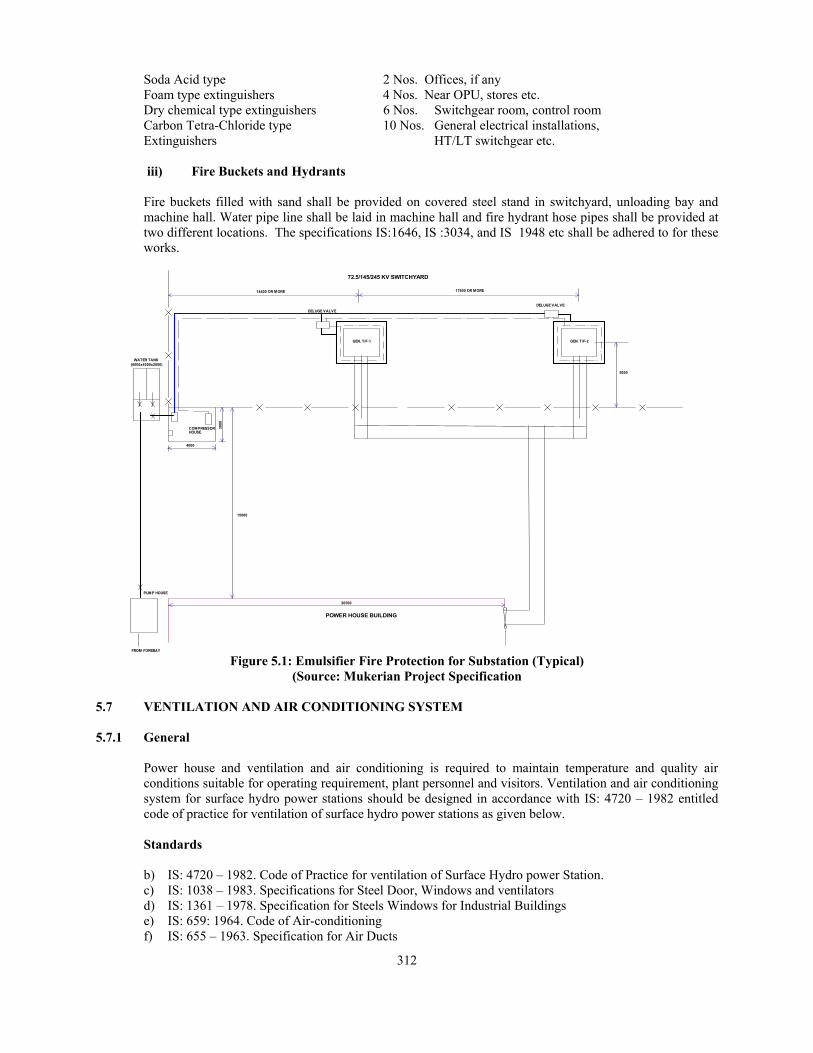
Emulsifier protection system shall be provided for protection against fire hazards for (two) numbers ------ kVA 12/72.5/145/245 kV Generator Transformers installed in the outdoor switchyard. Fire protection is not required for circuit breakers installed in the transformer circuits, feeders and bus coupler circuits as these are SF-6 type. This system shall consist of the following main equipment.
(i) Pump – motor set for water accumulation in the water tank 1 Set (ii) Air compressor with receiver etc 1 No. (iii) Pump set to provide water under pressure 1 Set (iv) Deluge valves 2 Nos. (v) Quartzoide glass bulbs 32 Nos. (vi) Nozzle 64 Nos. (vii) Air and water pipe lines As required (viii) General air and water valves etc As required
Both the transformers should be provided with quartzite bulbs as fire detectors. 10 bulbs shall be installed on lower air pipe ring and other 10 bulbs on upper air pipe ring at strategic locations. The water pipe line shall also be installed in two (lower and upper) layers with water nozzles at specified location so that the complete transformer is covered through water spray.
The air pressure and water lines around transformer shall be of 15 mm and 40 mm dia. G.I. pipe respectively. Separate deluge valves shall be installed near transformer with a common water header from the pump. The pump motor set shall be installed in the pump house by the side of switchyard fence and shall be capable of providing adequate discharge at 5.25 kg/cm2 pressure on deluge valves. The water tank of size 6 m x 4 m x 2 m shall be constructed in excavated ground adjacent to the pump house. The air compressor suitable to provide 3 kg/cm2 pressure in deluge valve shall also be installed in the pump house. Another pump-motor set of adequate capacity shall be installed near Fore Bay of the power house along with the water supply line for the tank. The scheme is typically indicated in Figure 5.1.
The scheme shall have auto operation of air compressor on preset air pressure. Simultaneously the pump motor set shall also be made auto operative with operation of deluge valve as per the requirement. The alarm/indication panel shall be located in control room and provisions of continuous siren till fire continued shall be essentially required.
Fire Protection of other Areas
The remaining areas of the power house shall be provided with following fire fighting arrangements.
i) Fire detectors
The following locations of equipment shall be provided with fire/smoke detectors. These detectors shall be installed above the equipments. 1. Control room-above control/relay panels, battery chargers etc. 2. Switchgear room-415 volts and 11kV switchgear, generator terminal equipment, excitation panel etc. 3. Any other location deemed necessary.
The above detectors shall initiate alarm and indication in the fire alarm panel to be installed in the control room. The indication shall identify the location of smoke/fire for taking corrective action.
ii) Portable Fire Extinguishers
Various types of fire extinguishers of requisite capacity shall be located at appropriate locations in the power house as follows. CO2 type fire extinguishers 6 Nos. Control room, switchgear room
312
Soda Acid type 2 Nos. Offices, if any Foam type extinguishers 4 Nos. Near OPU, stores etc. Dry chemical type extinguishers 6 Nos. Switchgear room, control room Carbon Tetra-Chloride type 10 Nos. General electrical installations, Extinguishers HT/LT switchgear etc.
iii) Fire Buckets and Hydrants
Fire buckets filled with sand shall be provided on covered steel stand in switchyard, unloading bay and machine hall. Water pipe line shall be laid in machine hall and fire hydrant hose pipes shall be provided at two different locations. The specifications IS:1646, IS :3034, and IS 1948 etc shall be adhered to for these works.
COMPRESSORHOUSE
WATER TANK
72.5/145/245 KV SWITCHYARD
DELUGE VALVEDELUGE VALVE
GEN. T/F-2
(6000x4000x2000)
15000
PUMP HOUSE
14400 OR MORE 17600 OR MORE
3000
4000
5000
POWER HOUSE BUILDING
20500
GEN. T/F-1
FROM FOREBAY Figure 5.1: Emulsifier Fire Protection for Substation (Typical)
(Source: Mukerian Project Specification 5.7 VENTILATION AND AIR CONDITIONING SYSTEM
5.7.1 General
Power house and ventilation and air conditioning is required to maintain temperature and quality air conditions suitable for operating requirement, plant personnel and visitors. Ventilation and air conditioning system for surface hydro power stations should be designed in accordance with IS: 4720 – 1982 entitled code of practice for ventilation of surface hydro power stations as given below.
Standards
b) IS: 4720 – 1982. Code of Practice for ventilation of Surface Hydro power Station. c) IS: 1038 – 1983. Specifications for Steel Door, Windows and ventilators d) IS: 1361 – 1978. Specification for Steels Windows for Industrial Buildings e) IS: 659: 1964. Code of Air-conditioning f) IS: 655 – 1963. Specification for Air Ducts

313
5.7.2 Types of Ventilation
The ventilation may be of following types:
a) Natural, that is, by forces set in motion by the heat of sun, namely, winds b) Forced or artificial, that is, by extraction or propulsion.
5.7.3 General Rules For Design
Natural Ventilation
• Thorough ventilation of power house building should be aimed at by the provision of adequate windows and ventilators.
• Provision of Windows and Ventilators - The object of providing windows and ventilators is two-fold, that is, to get fresh Air and light. The minimum area of windows and ventilators to be provided in power house building should be one-tenth of the floor area. However, efforts should be made to increase it to one-fifth of the floor area. Windows should be well distributed and be located on windward side at low level ri should not, as far as possible, be obstructed by adjoining structures or partitions. When wind direction is variable, windows should be provided on all sides, if possible. Effort should be made to develop cross-ventilation. For protection against fire, it is preferable to provide steel doors and windows in power house and auxiliary rooms. Reference may be made to IS :1038-1975 and IS :136l-1978. The ventilators should be fixed as high as possible for proper expulsion of warm air. Full advantage should be taken of sunshine which is important in ventilation. Its availability depends on the orientation of the power house which in turn may depend on site condition. In providing openings, measures to guard against entry of birds, moths, etc, should be taken care of.
Forced Ventilation
i) Forced ventilation system is designed keeping the inlet fan capacity 10 percent more than the exhaust
fan capacity*. *Code of practice for industrial ventilation Steel doors, windows and ventilators (second revision). Steel windows for industrial buildings (first revision). ii) Unassigned rooms and storage rooms should be carefully considered, so that sufficient ventilation
may be provided in those areas which might be used for purpose requiring additional ventilation in the future.
iii) In portions of the power station building where moisture condensation is anticipated, dehumidified air should be supplied to prevent condensation, as condensation causes deterioration of point, corrosion of metal surfaces and breakdown of insulation on electrical equipment.
iv) The quantity of air required for the power station building should be worked out from the number of air changes preferred for the various premises of the building as given in Table 5.1.
TABLE 5.1PREFERRED NUMBER OF AIR CHANGES
POWEU HOUSE PREMISES PREFERRED AIR CHANGES PER Hour
Main generator room, dark room, light and heavy storage rooms, dewatering and drainage sumps, record room
2
Passage, approach gallery, pipe gallery, ventilation equipment room, governor gallery, cable gallery, dewatering drainage-pump room or gallery
4
Oil storage and oil purification rooms, service (pump ) gallery, oil sludge room, compressor room, terminal board room, machine shop, tool room, pipe shop, electrical laboratory, fan room, battery room, telephone and communication equipment room
6
Offices, reception room, toilets, and control room 8

314
v) One air change per hour means that the quantity of air equivalent to the total volume of the room
is supplied to and exhausted from the room each hour. This air may be all outside air or a part of the-circulated air, depending upon the oxygen content.
iv) The proportion of outside air to the circulated air supplied to a room depends upon temperature conditions, number of occupants and kind of equipment installed in the room.
v) The number of air changes per hour provided for any room is dependent upon the number of occupants. The air should be changed at the rate of l'5ms/min per person and not less than 0.3m3/min. of this air should come from outside sources.
vi) The number of air changes per hour provided for rooms containing equipment generating heat should necessarily be increased, depending on the amount of heat to be carried out by the ventilating system.
vii) For medium climates, the maximum temperature rise of air carrying off heat of transformers should be limited to 20°C, and for hot climates the temperature rise should be limited to 16°C; however, the final temperature of the air exhausted should not exceed 45°C.
viii) Air supplied to rooms containing special mechanical or electrical equipment should be filtered arid circulation maintained at a minimum, through diffusers, to prevent the accumulation of dust on sensitive mechanisms. The relative humidity of air supplied should not be higher than 65 percent.
ix) Rooms which may contain air contaminated with objectionable or harmful odours, carbon dioxide gas or smoke, should be exhausted directly to the outside of the building.
x) When heating or cooling units are provided in the power house, their effect on the quantity and temperature or air circulating through the building should be considered.
xi) The spacing of supply and exhaust openings in long rooms or galleries should be such that sufficient air changes per hour are provided along the full length of the room.
5.7.4 Fans
Forced air ventilation is provided by propeller, axial or centrifugal type fans powered by electric motors. Propeller fans may be used either to supply or exhaust where no duct system, filters or other restrictions are in the air passage. When duct system is used, axial or centrifugal fans may be used for any type of operation involving the movement of air and may be accompanied by filters, and coolers or heaters where cleaning and tempering of supply air is required. Choice of a particular type of fan may be made by consulting the fan manufacturers data, which give full operating characteristics with a preferred range of operation for a particular fan.
5.7.5 Air Intake And Exhaust -Openings
Openings are provided for intake and exhaust of air where outside air is required for ventilation. Where natural ventilation is used, the opening of windows is sometimes sufficient. For forced ventilation, special openings are required. The number of openings for intake and exhaust of air depends on the space arrangement in the .building, on the size of the building and the design of the ventilation system. Small Power plants may have one opening of each type. For larger power plants, separate outside air intake should be installed for the control, service and main unit bays. Each intake should be provided with storm louvers, screens, and dampers for controlling the mixture of outside and circulated air. The obstructive effect of the louvers should be compensated for by making the gross area of the initial intake twice the area of the connecting duct. When filters are used, the area should be increased to accommodate the required filter area.
Air opening may be placed anywhere on the exposed walls or roof of the power plant building, except that, in order to reduce dust intake, air intake should be at least 1.25 m above ground or deck level.

315
Air is exhausted from the building through exhaust openings provided with louvers or by axial-flow exhaust fans located near the roof in the main generator room. Normally, the number of exhaust openings may be more than the air inlet openings, since the spaces to be exhausted are seldom located in the same general area, nor do they have common requirements. Individual centrifugal fans and connecting ducts are usually installed to exhaust air from toilets, battery rooms and oil storage rooms. The size of air openings is dependent on noise level, and to a lesser degree, on horse power requirements, since the smaller the opening the higher will be the noise level and the resistance. The size of air openings may also be worked out from the air velocity as recommended in Table 5.2,which will be found to give satisfactory results in designing conventional systems.
5.7.6 Air Cleaning
It is desirable to clean the air entering the power plant building in order to remove the air-borne dust particles which, if allowed to enter the building, may have an abrasive effect on rotating machinery, interfere with the operation of electric or electronic devices, and may, otherwise settle on equipment, giving a dirty appearance. The air filters are usually located upstream of the fan. The size of the air filters may be determined by the recommended velocity of air passing as given in Table 5.2. The choice of the air filter may be made by reference to the manufacturer's catalogues.
5.7.7 Air-Conditioning
When the desired temperatures and humidities inside the hydro power station are not obtainable by ordinary ventilation, air-conditioning may be resorted to bv heating or cooling the entering air to the desired temperature to maintain comfortable working conditions in the premises occupied by working personnel. The premises where it will be desirable to provide air-conditioning are control, room, machine shop, offices, reception room, first-aid room, dark room, electrical laboratory, switchgear -and terminal board room and telephone and carrier communication room. For air-conditioning reference may be made to IS: 659.
In general, all rooms, used by sedentary personnel should be maintained at 22°C with a relative humidity of about 50 percent, or in special cases local radiant type portable heaters may be used for the space actually occupied. Operation of the air-conditioning system should be independent of the main ventilating system and the control of the system should be automatic by means of thermostatic devices. Heating and cooling load computations may be based on currently accepted standard practice.
TABLE 5.2 RECOMMENDED AND MAXIMUM DUCT VELOCITIES FOR SYSTEMS IN
POWER HOUSE BUILDINGS
Sl No. Designation Recommended Velocities Maximum Velocities
i) Outer air intakes 150 370 ii) Filters* 110 110 iii) Heating coils* 180 210 iv) Air washers 150 150 v) Fan outlets 500-730 850 vi) Main ducts 370-550 670 vii) Branch ducts 250-300 550 viii) Branch risers 250 500
*These velocities are for total face area and not the net free area; other velocities in the table are for net free area. The net free area is the total minimum area of the opening in the face of a coil, grille, register or louver through which air can pass.

316
5.7.8 Ducts
Where positive ventilation requires ducts for proper air distribution, considerable advantage may be achieved by incorporating the ducts into the building structure and by having the interior surfaces carefully finished to render them smooth and air-tight.
Where metal duct work is installed, it’ should be fabricated from galvanized steel or aluminum sheets, and should conform to IS: 655-1963.
The transfer of air by ducts; from source to delivery point, should be as direct as practicable with the fewest possible bends. Flexible connections should be provided between fans and ductwork to prevent the noise of fan vibration being transmitted directly to the sheet-metal ducts.
The size of the air ducts are worked out from the permissible air velocities given in Table 5.2.
Supply and exhaust ducts of acid battery rooms are painted with acid resistant paint both inside and outside.
Ducts are suitably insulated wherever required.
5.7.9 Air Distribution Control
To regulate the flow of air in a ventilating system, control dampers are provided throughout. At outside air intakes, multi-louver dampers should be used to control the amount of air admitted. A similar damper is required on inside air intakes to control the amount of re-circulated air. These two dampers are interconnected to permit regulation of the proportion of outside air to inside air used in the ventilating system. These may be operated manually or automatically. Back-draft dampers are used where it is desired to prevent a reverse flow of the air, such as the air supply duct to a battery room. Exhaust ducts from rooms containing a fire hazard have dampers which can be automatically and manually closed in case of fire. Discharge openings, provided with propeller exhaust fans, are fitted with motor or mechanically operated type multi-louver dampers, which will open and close automatically when the fan motor starts and stops.
5.7.10 Air Conditioning and Ventilation System Recommended
SHP above 100 kW and up to 25,000 kW capacity
Provide air conditioning by individual air conditioners in the required areas.
Provide ventilation system for required no. of air changes by exhaust fans or forced air fans. SHP Micro Hydro Range Provide exhaust fans in the generator hall.
5.8 WATER LEVEL SENSING
Forebay and tailrace water level sensing is required for all powerhouses for operational monitoring and control. Tailrace level sensing is required for all canal fall powerhouses for optimum power generation and all powerhouses with reaction turbine for maintaining minimum tailrace level from cavitation considerations.
5.8.1 Water Level Sensing specification
Scope of Supply
Water level measuring & transmitting device for intake and tail race channel is provided with redundant level monitoring system – one float operated and the other non float operated. The error

317
should not exceed ± 10% of total measuring range. The equipment should comprise of the following.
• Level transducer with transmitting device for intake with complete mounting arrangement,
• Level transducer with transmitting device for tail race with complete mounting arrangement,
• Water level signals receiving and processing device with mounting arrangement,
• Interconnecting cables between sensors, transmitters and control unit.
General Design and Constructional Requirements: i) For monitoring water level upstream of intake gates, one set of suitable electronic level sensor (strain
gauge or capacitance type) and transmitter unit is provided for transmitting the water level signal to controlling unit mounted in control & metering panels in control room. One set of identical level sensor and transmitter unit is provided for water level in tail race. The signals from both the units are analogue signals in the form of 4 to 20 mA. These signals are processed in centralized control unit. Necessary power supply to sensors and transmitting units are provided from control unit.
ii) Output signals for fore-bay level, tail race level and their difference are provided from the control unit for further utilization in Governor electronic cubicle and SCADA. Digital indictors are provided in the control unit for indicating fore-bay level, tail race level and their difference i.e. gross head. The device should be of reliable make.
iii) The level sensors are mounted inside a pipe in such a way that oscillations in water level are damped out and pipe do not get clogged by floating materials or silt etc. complete with mounting accessories.
iv) Level sensors should be hermitically sealed and it should be possible to take out and calibrate them easily.
5.9 OIL SYSTEM
Two types of oil systems provided in a hydro station are as follows:
a) Common oil for unit lubrication and governor system b) Insulating oil for transformers
Storage, pumping, purification and piping faculties for two types of oils are similar but require complete separation. System requirements for the lubricating oil system are as follows:
a) Filling dirty oil storage tank from tank car or truck.
b) Moving oil from clean oil storage tank by either the purifier or transfer pump to the generator turbine unit.
c) Draining or returning overflow oil from the generator turbine unit to the dirty oil storage tank.
d) Moving oil from either storage tank to a tank car or truck for disposal.
e) Flushing of any supply line to generator turbine units.
f) Recirculating oil in any equipment on generator turbine unit through purifier and back to equipment.
g) Recirculating oil from any storage tank through purifier and back to tank.
Large Powerhouse
Oil storage rooms with provision for dirty oil and purified oil piping is provided. Oil purifiers generally of centrifugal type are provided in the oil purification room.
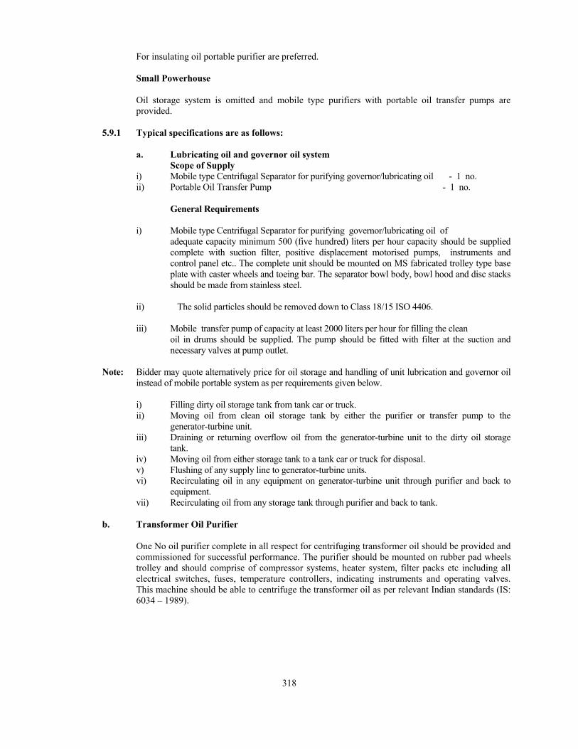
318
For insulating oil portable purifier are preferred.
Small Powerhouse
Oil storage system is omitted and mobile type purifiers with portable oil transfer pumps are provided.
5.9.1 Typical specifications are as follows:
a. Lubricating oil and governor oil system Scope of Supply i) Mobile type Centrifugal Separator for purifying governor/lubricating oil - 1 no. ii) Portable Oil Transfer Pump - 1 no. General Requirements i) Mobile type Centrifugal Separator for purifying governor/lubricating oil of
adequate capacity minimum 500 (five hundred) liters per hour capacity should be supplied complete with suction filter, positive displacement motorised pumps, instruments and control panel etc.. The complete unit should be mounted on MS fabricated trolley type base plate with caster wheels and toeing bar. The separator bowl body, bowl hood and disc stacks should be made from stainless steel.
ii) The solid particles should be removed down to Class 18/15 ISO 4406. iii) Mobile transfer pump of capacity at least 2000 liters per hour for filling the clean
oil in drums should be supplied. The pump should be fitted with filter at the suction and necessary valves at pump outlet.
Note: Bidder may quote alternatively price for oil storage and handling of unit lubrication and governor oil
instead of mobile portable system as per requirements given below.
i) Filling dirty oil storage tank from tank car or truck. ii) Moving oil from clean oil storage tank by either the purifier or transfer pump to the
generator-turbine unit. iii) Draining or returning overflow oil from the generator-turbine unit to the dirty oil storage
tank. iv) Moving oil from either storage tank to a tank car or truck for disposal. v) Flushing of any supply line to generator-turbine units. vi) Recirculating oil in any equipment on generator-turbine unit through purifier and back to
equipment. vii) Recirculating oil from any storage tank through purifier and back to tank.
b. Transformer Oil Purifier
One No oil purifier complete in all respect for centrifuging transformer oil should be provided and commissioned for successful performance. The purifier should be mounted on rubber pad wheels trolley and should comprise of compressor systems, heater system, filter packs etc including all electrical switches, fuses, temperature controllers, indicating instruments and operating valves. This machine should be able to centrifuge the transformer oil as per relevant Indian standards (IS: 6034 – 1989).

319
REFERENCES
1. U. S. Army Corps of Engineers - Manual no. EM 1110-4-4205, Hydro electric power plants mechanical designs dated 30 June 1995.
2. Teachers manual - Water Resources Development (Hydropower Development) for Engineering Degree Programme Elective Course (for Branches in Electrical/Mechanical/ Instrumentation/'Electronic Engineering) Alternate Hydro Energy Centre
3. Standards/manuals/Guidelines for Small Hydro Development - Guidelines for selection auxiliaries for SHP up to 25 MW, Alternate Hydro Energy Centre, Aug. 11. 2008.
4. Indian Standard, (IS) International Standard IEC and codes