Embed Size (px)
Citation preview
Drafting and Design Presentation Standards Volume 3: Structural Drafting Standards Chapter 5: Notes August 2018

Drafting and Design Presentation Standards Manual, Transport and Main Roads, August 2018
Copyright
http://creativecommons.org/licenses/by/3.0/au/
© State of Queensland (Department of Transport and Main Roads) 2018
Feedback: Please send your feedback regarding this document to: [email protected]
Drafting and Design Presentation Standards Manual, Transport and Main Roads, August 2018 i
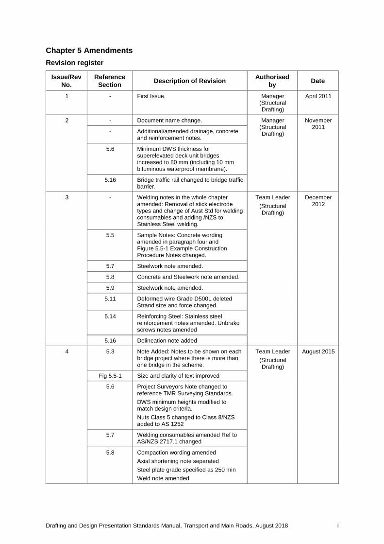
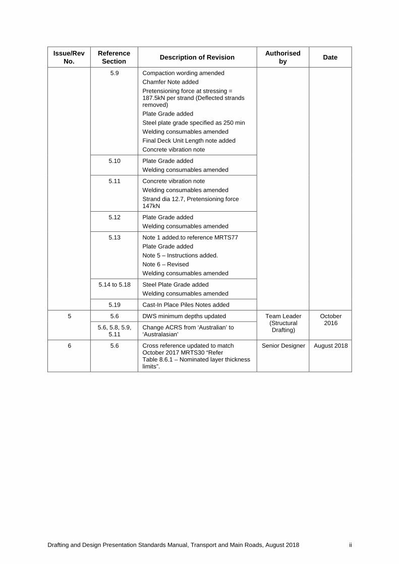
Chapter 5 Amendments Revision register
Issue/Rev No.
Reference Section Description of Revision Authorised
by Date
1 - First Issue. Manager (Structural Drafting)
April 2011
2 - Document name change. Manager (Structural Drafting)
November 2011
- Additional/amended drainage, concrete and reinforcement notes.
5.6 Minimum DWS thickness for superelevated deck unit bridges increased to 80 mm (including 10 mm bituminous waterproof membrane).
5.16 Bridge traffic rail changed to bridge traffic barrier.
3 - Welding notes in the whole chapter amended: Removal of stick electrode types and change of Aust Std for welding consumables and adding /NZS to Stainless Steel welding.
Team Leader (Structural Drafting)
December 2012
5.5 Sample Notes: Concrete wording amended in paragraph four and Figure 5.5-1 Example Construction Procedure Notes changed.
5.7 Steelwork note amended.
5.8 Concrete and Steelwork note amended.
5.9 Steelwork note amended.
5.11 Deformed wire Grade D500L deleted Strand size and force changed.
5.14 Reinforcing Steel: Stainless steel reinforcement notes amended. Unbrako screws notes amended
5.16 Delineation note added
4 5.3 Note Added: Notes to be shown on each bridge project where there is more than one bridge in the scheme.
Team Leader (Structural Drafting)
August 2015
Fig 5.5-1 Size and clarity of text improved
5.6 Project Surveyors Note changed to reference TMR Surveying Standards. DWS minimum heights modified to match design criteria. Nuts Class 5 changed to Class 8/NZS added to AS 1252
5.7 Welding consumables amended Ref to AS/NZS 2717.1 changed
5.8 Compaction wording amended Axial shortening note separated Steel plate grade specified as 250 min Weld note amended
Drafting and Design Presentation Standards Manual, Transport and Main Roads, August 2018 ii
Issue/Rev No.
Reference Section Description of Revision Authorised
by Date
5.9 Compaction wording amended Chamfer Note added Pretensioning force at stressing = 187.5kN per strand (Deflected strands removed) Plate Grade added Steel plate grade specified as 250 min Welding consumables amended Final Deck Unit Length note added Concrete vibration note
5.10 Plate Grade added Welding consumables amended
5.11 Concrete vibration note Welding consumables amended Strand dia 12.7, Pretensioning force 147kN
5.12 Plate Grade added Welding consumables amended
5.13 Note 1 added.to reference MRTS77 Plate Grade added Note 5 – Instructions added. Note 6 – Revised Welding consumables amended
5.14 to 5.18 Steel Plate Grade added Welding consumables amended
5.19 Cast-In Place Piles Notes added
5 5.6 DWS minimum depths updated Team Leader (Structural Drafting)
October 2016
5.6, 5.8, 5.9, 5.11
Change ACRS from ‘Australian’ to ‘Australasian’
6 5.6 Cross reference updated to match October 2017 MRTS30 “Refer Table 8.6.1 – Nominated layer thickness limits”.
Senior Designer August 2018
Drafting and Design Presentation Standards Manual, Transport and Main Roads, August 2018 iii
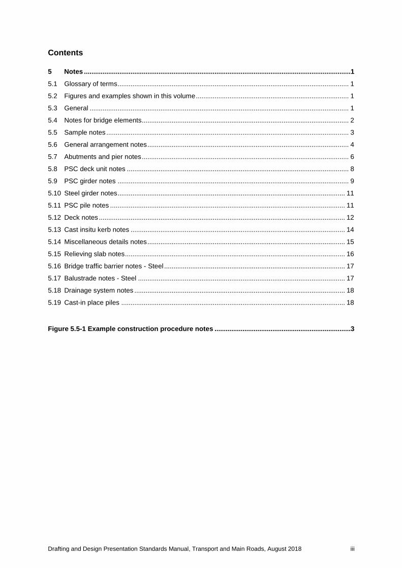
Contents
5 Notes ...............................................................................................................................................1
5.1 Glossary of terms ............................................................................................................................ 1
5.2 Figures and examples shown in this volume .................................................................................. 1
5.3 General ........................................................................................................................................... 1
5.4 Notes for bridge elements ............................................................................................................... 2
5.5 Sample notes .................................................................................................................................. 3
5.6 General arrangement notes ............................................................................................................ 4
5.7 Abutments and pier notes ............................................................................................................... 6
5.8 PSC deck unit notes ....................................................................................................................... 8
5.9 PSC girder notes ............................................................................................................................ 9
5.10 Steel girder notes .......................................................................................................................... 11
5.11 PSC pile notes .............................................................................................................................. 11
5.12 Deck notes .................................................................................................................................... 12
5.13 Cast insitu kerb notes ................................................................................................................... 14
5.14 Miscellaneous details notes .......................................................................................................... 15
5.15 Relieving slab notes ...................................................................................................................... 16
5.16 Bridge traffic barrier notes - Steel ................................................................................................. 17
5.17 Balustrade notes - Steel ............................................................................................................... 17
5.18 Drainage system notes ................................................................................................................. 18
5.19 Cast-in place piles ........................................................................................................................ 18
Figure 5.5-1 Example construction procedure notes .........................................................................3
Volume 3: Structural Drafting Standards – Chapter 5 Notes
Drafting and Design Presentation Standards Manual, Transport and Main Roads, August 2018 1
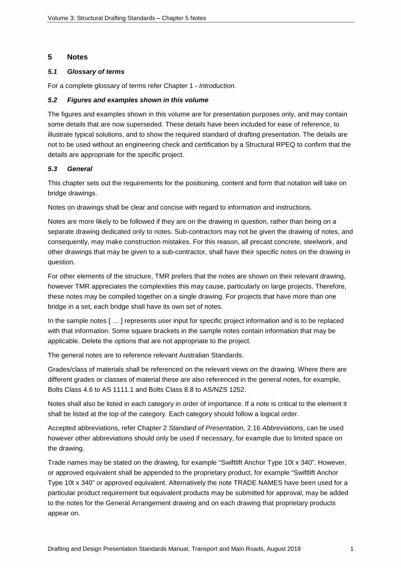
5 Notes
5.1 Glossary of terms
For a complete glossary of terms refer Chapter 1 - Introduction.
5.2 Figures and examples shown in this volume
The figures and examples shown in this volume are for presentation purposes only, and may contain some details that are now superseded. These details have been included for ease of reference, to illustrate typical solutions, and to show the required standard of drafting presentation. The details are not to be used without an engineering check and certification by a Structural RPEQ to confirm that the details are appropriate for the specific project.
5.3 General
This chapter sets out the requirements for the positioning, content and form that notation will take on bridge drawings.
Notes on drawings shall be clear and concise with regard to information and instructions.
Notes are more likely to be followed if they are on the drawing in question, rather than being on a separate drawing dedicated only to notes. Sub-contractors may not be given the drawing of notes, and consequently, may make construction mistakes. For this reason, all precast concrete, steelwork, and other drawings that may be given to a sub-contractor, shall have their specific notes on the drawing in question.
For other elements of the structure, TMR prefers that the notes are shown on their relevant drawing, however TMR appreciates the complexities this may cause, particularly on large projects. Therefore, these notes may be compiled together on a single drawing. For projects that have more than one bridge in a set, each bridge shall have its own set of notes.
In the sample notes [ … ] represents user input for specific project information and is to be replaced with that information. Some square brackets in the sample notes contain information that may be applicable. Delete the options that are not appropriate to the project.
The general notes are to reference relevant Australian Standards.
Grades/class of materials shall be referenced on the relevant views on the drawing. Where there are different grades or classes of material these are also referenced in the general notes, for example, Bolts Class 4.6 to AS 1111.1 and Bolts Class 8.8 to AS/NZS 1252.
Notes shall also be listed in each category in order of importance. If a note is critical to the element it shall be listed at the top of the category. Each category should follow a logical order.
Accepted abbreviations, refer Chapter 2 Standard of Presentation, 2.16 Abbreviations, can be used however other abbreviations should only be used if necessary, for example due to limited space on the drawing.
Trade names may be stated on the drawing, for example “Swiftlift Anchor Type 10t x 340”. However, or approved equivalent shall be appended to the proprietary product, for example “Swiftlift Anchor Type 10t x 340” or approved equivalent. Alternatively the note TRADE NAMES have been used for a particular product requirement but equivalent products may be submitted for approval, may be added to the notes for the General Arrangement drawing and on each drawing that proprietary products appear on.
Volume 3: Structural Drafting Standards – Chapter 5 Notes
Drafting and Design Presentation Standards Manual, Transport and Main Roads, August 2018 2
On any drawing, where a note or reference applies to a particular view, section or detail only, it is to be placed as close as possible to the point to which it applies. The leader dimension should be placed at the beginning of the note text or at the end of the note text, for example:
200 dia holes for scuppers
(Girder Type G1)
200 dia holes for scuppers
(Girder Type G1)
Where a note is of greater significance it is to be presented in box so that it increases its visibility on the drawing, for example:
• for headstock reinforcement refer Drg No 123456
Or use capital letters for greater visibility, for example:
• fastener Type 1 only to be galvanised
DO NOT ISOLATE TEXT. For example Class 4.6 shall not be shown with Class on one line and 4.6 on the next line. Similarly keep text such as AS/NZS 1252 together on one line. It is not good practice to have one word isolated on the last line, for example:
• blinding concrete 50 nominal thickness.
5.4 Notes for bridge elements
The notes shall be placed under the heading NOTES at the bottom right-hand corner of the drawing.
The notes are grouped in categories that may include, but are not limited to:
• General notes such as lifting of precast components and foundation reports
• Concrete
• Reinforcement
• Strands
• Steelwork
• Transverse stressing bars
• Welding
• Voids
• Details of existing structures, and
• Notes for widenings.
Other project specific notes that may be applicable to an element should be added in the appropriate section within the notes or at the end. The first word or words of the notes indicating the category of that group are to be capitalised, for example HEIGHTS are calculated, TRADE NAMES have been used.
Volume 3: Structural Drafting Standards – Chapter 5 Notes
Drafting and Design Presentation Standards Manual, Transport and Main Roads, August 2018 3
5.5 Sample notes
Typical notes for drawing elements are shown on the following pages as a guide. Only the notes relevant to the specific project should be used.
Add only the project specific information from the square brackets within the sample notes. Information shown in bold italic text in brackets at the end of each sample note is not to be shown and is provided as an example of where these notes should be used.
In general the grade of steel, finish of stainless steel and so on, should be called up on the relevant detail on the drawing and the relevant Australian Standard should be referred to in the notes. In cases where there is only one grade of material mentioned on the drawing the grade should be called up in the general notes.
Concrete Class and Strength and cover to reinforcing steel values in the sample notes are based on exposure classification B2. These values are to be adjusted accordingly if another exposure classification is used. Refer to AS 5100, Bridge Design for the full range of exposure classifications.
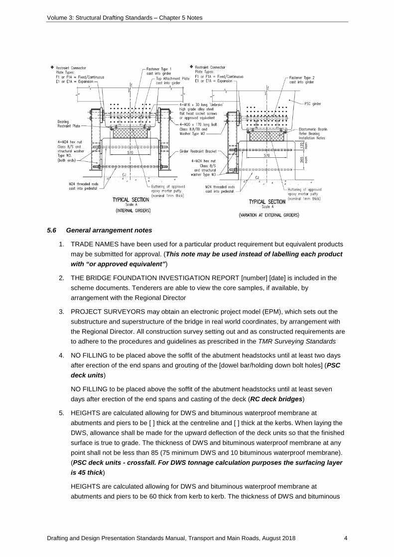
In some cases a construction procedure is needed for an element, for example girder anchorages. In these cases the construction procedure is to be positioned as near as possible to the relevant view. Refer Figure 5.5 1 Example Construction Procedure Notes.
Figure 5.5-1 Example construction procedure notes
BEARING INSTALLATION NOTES: 1. Bearing design is based on the girders and restraints being installed at 100 days from
casting. Approval to proceed must be obtained from the designer if not installed after 85 days and before 180 days from casting.
2. Bearing design is based on the ambient temperature at installation of 25°C. Approval to proceed must be obtained from the designer if temperature is less than 20°C or more than 30°C at time of installation.
GIRDER INSTALLATION AND RESTRAINT PROCEDURE: 1. Install restraint bracket assembly (loose M24 nuts initially - tighten at Step four). 2. Install temporary adjustable stools / jacks on top of the headstock, positioned to support the
girder. Stools to be of sufficient strength to support the weight of the girder, and of such a height under load that the soffit of the girder will clear the top of the bearing pads by 1 mm at the closest point.
3. Immediately prior to installing the girder, apply a 1 mm nominal thick approved epoxy putty between the bearing and the underside of the bearing restraint plate. The epoxy shall have a cured compressive strength of not less than 60MPa.
4. The girder shall then be lowered into position and supported on the temporary stools. Any excess epoxy squeezed out shall be removed before it has set.
5. If the epoxy sets before completion of this operation, the girder shall be lifted off and all contact surfaces cleaned before repeating the process.
6. After the epoxy has fully cured over a period of not less than 48 hours, the temporary stools shall be removed without dislodging the girder.
7. During installation, the girders shall be restrained longitudinally and laterally by the Girder Restraint Brackets fitted to the bearing pedestals.
Volume 3: Structural Drafting Standards – Chapter 5 Notes
Drafting and Design Presentation Standards Manual, Transport and Main Roads, August 2018 4
5.6 General arrangement notes
1. TRADE NAMES have been used for a particular product requirement but equivalent products may be submitted for approval. (This note may be used instead of labelling each product with “or approved equivalent”)
2. THE BRIDGE FOUNDATION INVESTIGATION REPORT [number] [date] is included in the scheme documents. Tenderers are able to view the core samples, if available, by arrangement with the Regional Director
3. PROJECT SURVEYORS may obtain an electronic project model (EPM), which sets out the substructure and superstructure of the bridge in real world coordinates, by arrangement with the Regional Director. All construction survey setting out and as constructed requirements are to adhere to the procedures and guidelines as prescribed in the TMR Surveying Standards
4. NO FILLING to be placed above the soffit of the abutment headstocks until at least two days after erection of the end spans and grouting of the [dowel bar/holding down bolt holes] (PSC deck units)
NO FILLING to be placed above the soffit of the abutment headstocks until at least seven days after erection of the end spans and casting of the deck (RC deck bridges)
5. HEIGHTS are calculated allowing for DWS and bituminous waterproof membrane at abutments and piers to be [ ] thick at the centreline and [ ] thick at the kerbs. When laying the DWS, allowance shall be made for the upward deflection of the deck units so that the finished surface is true to grade. The thickness of DWS and bituminous waterproof membrane at any point shall not be less than 85 (75 minimum DWS and 10 bituminous waterproof membrane). (PSC deck units - crossfall. For DWS tonnage calculation purposes the surfacing layer is 45 thick)
HEIGHTS are calculated allowing for DWS and bituminous waterproof membrane at abutments and piers to be 60 thick from kerb to kerb. The thickness of DWS and bituminous
Volume 3: Structural Drafting Standards – Chapter 5 Notes
Drafting and Design Presentation Standards Manual, Transport and Main Roads, August 2018 5
waterproof membrane at any point shall not be less than 60 (50 minimum DWS and 10 bituminous waterproof membrane). (RC deck – crowned with two way crossfall. For DWS tonnage calculation purposes the surfacing layer is 45 thick)
HEIGHTS are calculated allowing for DWS and bituminous waterproof membrane at nd piers to be [ ] thick from kerb to kerb. When laying the DWS, allowance shall be made for the upward deflection of the deck units so that the finished surface is true to grade. The thickness of DWS and bituminous waterproof membrane at any point shall not be less than 85 (75 minimum DWS and 10 bituminous waterproof membrane). (PSC deck units – superelevation. For DWS tonnage calculation purposes the surfacing layer is 45 thick)
HEIGHTS are calculated allowing for DWS and bituminous waterproof membrane at abutments and piers to be 95 thick from kerb to kerb. The thickness of DWS and bituminous waterproof membrane at any point shall not be less than 95 (85 minimum DWS and 10 bituminous waterproof membrane). (RC deck – superelevation. For DWS tonnage calculation purposes the surfacing layer is 50 thick)
Note: The DWS notes above are based on a corrector course and a surfacing layer for a high speed environment (motorways or roads with a speed limit of 100km/h or greater). For calculation purposes, bituminous waterproof membrane is 10 mm thick, and is not included when calculating DWS quantities. Smaller thicknesses of DWS can be achieved in lower speed environments. Refer Table 8.6.1 – Nominated layer thickness limits in MRTS30 Asphalt Pavements.
6. A CLEAR GAP shall be maintained between abutment sidewall and outside face of the kerb and shall not be filled with cement mortar
7. FORMWORK for the deck shall be supported by the [PSC girders/deck units]. On no account is the formwork to be tommed from the ground
8. {REINFORCING STEEL to be read in conjunction with Standard Drawings 1043 and 1044. Reinforcing steel to be in accordance with AS/NZS 4671 and MRTS71 Reinforcing Steel. Deformed bars Grade D500N. Round bars Grade R250N
All carbon reinforcing steel to be Australasian Certification Authority for Reinforcing Steel (ACRS) certified.} (Only add these notes on General Arrangement and precast product drawings)
Reinforcement to be hot dip galvanised to AS/NZS 4680 where shown
Stainless steel reinforcing to be in accordance with BS 6744 and MRTS71A Stainless Steel Reinforcing. (S/S reinforcement)
Stainless steel reinforcing to be Duplex Grade 2205 or 316L. (S/S reinforcement)
9. STEELWORK to be fabricated to MRTS78 Fabrication of Structural Steelwork
Deck unit dowel bars Grade D500N to AS/NZS 4671, hot dip galvanised to AS/NZS 4680. (Bridges with deck units seated on cement mortar only, where the soffit of the bridge super-structure is above a 2000 ARI flood)
Holding down bolts for deck units Class 4.6 to AS 1111, nuts Class 5 to AS 1112.1 and washers to AS/NZS 3678. (Bridges with deck units seated on cement mortar only)
Volume 3: Structural Drafting Standards – Chapter 5 Notes
Drafting and Design Presentation Standards Manual, Transport and Main Roads, August 2018 6
Holding down bolts for deck units Class 8.8, nuts Class 8 to AS 1252, and washers to AS/NZS 3678. (Bridges with provision for future jacking)
Holding down bolts for steel girders Class 8.8, nuts Class 8 and washers for
Class 8.8 bolts to AS/NZS 1252
All anchors, bolts and nuts to be hot dip galvanised to AS 1214. All other steelwork to be hot dip galvanised to AS/NZS 4680 unless shown otherwise. Prior to galvanising all weld splatter and welding slag is to be removed
10. FOR DETAILS OF EXISTING STRUCTURE (BIS No [ ]) refer Drawing No’s [ ] to [ ] in the scheme documents. (Bridge widenings or when removing an existing bridge)
11. HEIGHTS AND DIMENSIONS to be verified on site before commencement of work
(Bridge Widenings).
5.7 Abutments and pier notes
1. TRADE NAMES have been used for a particular product requirement but equivalent products may be submitted for approval. (This note may be used instead of labelling each product with “or approved equivalent”)
2. CONCRETE to be in accordance with MRTS70 Concrete. Concrete to be S40/20, except as follows:
• Bearing pedestals S40/10
• Mass concrete N20/20
• Blinding concrete N20/20
Exposure classification B2. (Concrete Class, strength grade, and exposure classification may differ in accordance with AS 5100.5 Concrete)
All exposed edges to have 19 x 19 chamfers unless shown otherwise
3. REINFORCING STEEL to be read in conjunction with Standard Drawings 1043 and 1044 Reinforcing steel to be in accordance with AS/NZS 4671 and MRTS71 Reinforcing Steel
Minimum cover to reinforcing steel to be 55 unless shown otherwise
Spacing of ligatures in headstock may be altered slightly, if necessary, to clear formed holes
Reinforcement to be hot dip galvanised to AS/NZS 4680 where shown. (Where reinforcement is to be galvanised, for example bond bars into relieving slabs)
4. TOP 50 OF PSC PILES to be well scabbled prior to casting into [headstock/pile cap]. (This note may be shown on a detailed view on the abutment and pier drawings)
5. STEELWORK to be fabricated to MRTS78 Fabrication of Structural Steelwork. Steel liners to be Grade 250 (minimum) to AS/NZS 3678. (Cast-in-place piles) Steel piles to be Grade 300 (minimum) to AS/NZS 3679.1. (Driven steel piles)
Bolts Class 4.6 to AS 1111.1, nuts Class 5 to AS 1112.1, washers for Class 4.6 bolts to AS 1237.1
Bolts Class 8.8, nuts Class 8 and washers for Class 8.8 bolts to AS/NZS 1252
Volume 3: Structural Drafting Standards – Chapter 5 Notes
Drafting and Design Presentation Standards Manual, Transport and Main Roads, August 2018 7
All bolts and nuts to be hot dip galvanised to AS 1214. All other steelwork to be hot dip galvanised to AS/NZS 4680 unless shown otherwise. Prior to galvanising, all weld splatter and welding slag is to be removed
6. WELDING symbols to AS 1101.3
Structural Steel
All welding to AS/NZS 1554.1
All welds, except location tack welds, to be SP category
Welding consumables to be controlled hydrogen type: G493 to AS/NZS ISO 14341-B, or T493 to AS/NZS ISO 17632-B unless shown otherwise
Field joint welds shall be full penetration butt welds. (Cast-in-place piles)
Stainless Steel
Welding to AS/NZS 1554.6
Weld quality – Category 2B
Welding consumables to be 316L unless shown otherwise
Welding consumables to AS/NZS 1167.2 and/or AS/NZS 4854
Reinforcing Steel
(For reinforcing steel that shows welded laps - enter this group of notes)
Welding of bar splices to AS/NZS 1554.3
All welds, except location tack welds, to be SP category
Tack welding for location purposes to AS/NZS 1554.3
Welding shall not be carried out within 75 from any bent portion of the bar
Welding consumables to be controlled hydrogen type: G49X to AS/NZS ISO 14341-B or T49X to AS/NZS ISO 17632-B unless shown otherwise
(Direct butt splice and anchorage splice welds require the following consumables: G57X to AS/NZS ISO 14341-B, or T57X to AS/NZS IS0 17632-B)
Welding consumables to AS/NZS ISO 14341 or AS/NZS ISO 17632
(For reinforcing steel that shows NO welded laps - enter these notes only)
Tack welding for location purposes to AS/NZS 1554.3
Welding consumables to be controlled hydrogen type: G49X to AS/NZS ISO 14341-B or T49X to AS/NZS ISO 17632-B unless shown otherwise
7. A DATE PLATE is to be cast into the outside face of the left hand wingwall at Abutment A. (Abutments only)
8. A PERMANENT SURVEY MARK is to be cast into the top of the left hand wingwall at Abutment A. (Abutments only)
9. A 20 DEEP SAW CUT is to be made at the junction with new work prior to breaking back existing concrete. (Bridge widenings)
Volume 3: Structural Drafting Standards – Chapter 5 Notes
Drafting and Design Presentation Standards Manual, Transport and Main Roads, August 2018 8
10. EXISTING CONCRETE SURFACES to be well scabbled and cleaned with water blasting to remove all dust and loose particles before new work is placed. (Bridge widenings)
5.8 PSC deck unit notes
1. PSC DECK UNITS to be manufactured to MRTS73 Manufacture of Prestressed Concrete Members and Stressing Units
2. CONCRETE to be in accordance with MRTS70 Concrete. Concrete to be S50/20
Strength at transfer to be 40MPa minimum
Exposure classification B2. (Concrete Class, strength grade, and exposure classification may differ in accordance with AS 5100.5 Concrete)
Concrete shall be cast in rigid forms and subjected to intense compaction, utilising a combination of internal and external vibration. All chamfers where shown to be 25 x 25 unless shown otherwise. Top surface of all units to be treated as a construction joint unless shown otherwise. (Reinforced concrete deck bridges only)
3. REINFORCING STEEL to be read in conjunction with Standard Drawings 1043 and 1044. Reinforcing steel to be in accordance with AS/NZS 4671 and MRTS71 Reinforcing Steel. Deformed bars Grade D500N. Round bars Grade R250N. Minimum cover to reinforcing steel and strands to be 35 unless shown otherwise
All carbon reinforcing steel to be Australasian Certification Authority for Reinforcing Steel (ACRS) certified
4. STRANDS to MRTS73 Manufacture of Prestressed Concrete Members and Stressing Units and to AS/NZS 4672.1-7 wire ordinary-12.7-1870-Relax two and testing requirements to AS/NZS 4672.2. Pretensioning force at stressing = 147kN per strand. (12.7 mm strands) STRANDS to MRTS73 Manufacture of Prestressed Concrete Members and Stressing Units and to AS/NZS 4672.1-7 wire ordinary-15.2-1750-Relax two and testing requirements to AS/NZS 4672.2. Pretensioning force at stressing = 187.5kN per strand. (15.2 mm strands)
Ends of strands to be coated with three coats minimum of surface tolerant epoxy after grinding flush with ends of units. Each coat to be a minimum of 0.3 mm dry thickness
5. STEELWORK to be fabricated to MRTS78 Fabrication of Structural Steelwork
Steel plate to be Grade 250 minimum to AS/NZS 3678. Bolts Class 4.6 to AS 1111.1
All bolts and nuts to be hot dip galvanised to AS 1214. All other steelwork to be hot dip galvanised to AS/NZS 4680 unless shown otherwise. Prior to galvanising, all weld splatter and welding slag is to be removed. Stainless steel plate to ASTM A240M. (Cast in sockets for expansion joints)
Stainless steel round bar to ASTM A276. (Cast in sockets for expansion joints)
6. TRANSVERSE STRESSING BARS to MRTS73 Manufacture of Prestressed Concrete Members and Stressing Units and to AS/NZS 4672.1-bar-29-1030-P (with 300 mm minimum coarse tread at each end) and testing requirements to AS/NZS 4672.2. Transverse stressing force at lock off shall be 500kN
Coupler bars to AS/NZS 4672.1-bar-45-1030-T and testing requirements to AS/NZS 4672.2. (Bridge widenings and stage construction)
Volume 3: Structural Drafting Standards – Chapter 5 Notes
Drafting and Design Presentation Standards Manual, Transport and Main Roads, August 2018 9
7. TACK WELDING for location purposes to AS/NZS 1554.3 Clauses 3.3.1 and 3.3.2
Welding consumables to be G49X or T49X. (Direct butt splice and anchorage splice welds require the following consumables: G57X or T57X) Welding consumables to AS/NZS ISO 14341-B or AS/NZS ISO 17632-B
Welding symbols to AS 1101.3
Stainless Steel
Welding to AS/NZS 1554.6
Weld quality – Category 2B
Welding consumables to be E316L unless shown otherwise
Welding consumables to AS/NZS 1167.2 and/or AS/NZS 4854
8. Voids shall be cellular polystyrene Grade SL to AS 1366.3. (13-25 m long PSC deck units)
9. PVC DRAINAGE PIPES to AS/NZS 1260. (Units with scuppers)
10. FINAL DECK UNIT DIMENSIONS – When casting units the manufacturer shall make allowance in formwork for end formwork kick due to hog and axial shortening (equal amounts each end) so that the units assume the detailed dimensions shown at 100 days.
5.9 PSC girder notes
1. PSC GIRDERS to be manufactured to MRTS73 Manufacture of Prestressed Concrete Members and Stressing Units
2. CONCRETE to be in accordance with MRTS70 Concrete. Concrete to be S50/20
Strength at transfer to be 40MPa minimum
Exposure classification B2. (Concrete Class, strength grade, and exposure classification may differ in accordance with AS 5100.5 Concrete)
Concrete shall be cast in rigid forms and subjected to intense compaction, utilising a combination of internal and external vibration. Top surface of all girders to be treated as a construction joint unless shown otherwise
All chamfers where shown to be 25 x 25 maximum unless shown otherwise
3. REINFORCING STEEL to be read in conjunction with Standard Drawings 1043 and 1044 Reinforcing steel to be in accordance with AS/NZS 4671 and MRTS71 Reinforcing Steel Deformed bars Grade D500N. Round bars Grade R250N. Minimum cover to reinforcing steel and strands to be 35 unless shown otherwise
All carbon reinforcing steel to be Australasian Certification Authority for Reinforcing Steel (ACRS) certified. Stainless steel reinforcing to be in accordance with BS 6744 and MRTS71A Stainless Steel Reinforcing. (S/S reinforcement)
Stainless steel reinforcing to be Duplex Grade 2205 or 316L. (S/S reinforcement)
Volume 3: Structural Drafting Standards – Chapter 5 Notes
Drafting and Design Presentation Standards Manual, Transport and Main Roads, August 2018 10
4. STRANDS to MRTS73 Manufacture of Prestressed Concrete Members and Stressing Units and to AS/NZS 4672.1-7 wire ordinary-12.7-1870-Relax 2 and testing requirements to AS/NZS 4672.2. STRANDS to MRTS73 Manufacture of Prestressed Concrete Members and Stressing Units and to AS/NZS 4672.1-7 wire ordinary-15.2-1750-Relax 2 and testing requirements to AS/NZS 4672.2
Pretensioning force at stressing = [ ]kN per strand (Straight Strands)
= [ ]kN per strand (Deflected Strands)
Ends of strands to be coated with three coats minimum of surface tolerant epoxy after grinding flush with ends of units. Each coat to be a minimum of 0.3 mm dry thickness
5. STEELWORK to be fabricated to MRTS78 Fabrication of Structural Steelwork
Steel plate to be Grade 250 minimum to AS/NZS 3678
All steelwork to be hot dip galvanised to AS/NZS 4680 unless shown otherwise. Prior to galvanising, all weld splatter and welding slag is to be removed
6. WELDING symbols conform to AS 1101.3
Structural Steel
All welding to AS/NZS 1554.1
All welds, except location tack welds, to be SP category
Welding consumables to be controlled hydrogen type: G493 to AS/NZS ISO 14341-B or T493 to AS/NZS ISO 17632-B unless shown otherwise
Reinforcing Steel
(For reinforcing steel that shows welded laps - enter this group of notes)
Welding of bar splices to AS/NZS 1554.3
All welds, except location tack welds, to be SP category
Tack welding for location purposes to AS/NZS 1554.3 Clauses 3.3.1 and 3.3.2. Welding shall not be carried out within 75 from any bent portion of the bar
Welding consumables to be controlled hydrogen type: G493 to AS/NZS ISO 14341-B or T493 to AS/NZS ISO 17632-B unless shown otherwise
(Direct butt splice and anchorage splice welds require the following consumables: G57X to AS/NZS ISO 14341-B, or T57X to AS/NZS IS017632-B)
(For reinforcing steel that shows NO welded laps - enter these notes only)
Tack welding for location purposes to AS/NZS 1554.3 Clauses 3.3.1 and 3.3.2
Welding consumables to be controlled hydrogen type: G49X to AS/NZS ISO 14341-B or T49X to AS/NZS ISO 17632-B unless shown otherwise
7. VOIDS are based on a length of 5 m maximum. Alternative void arrangements may be submitted for approval
8. PVC DRAINAGE PIPES to AS/NZS 1260 (Girders with scuppers)
Volume 3: Structural Drafting Standards – Chapter 5 Notes
Drafting and Design Presentation Standards Manual, Transport and Main Roads, August 2018 11
9. FINAL GIRDER DIMENSIONS – When casting girders the manufacturer shall make allowance in formwork for end kick and axial shortening (equal amounts each end) so that the girder assumes the dimensions shown on the drawings at 100 days.
5.10 Steel girder notes
1. STEELWORK to be fabricated to MRTS78 Fabrication of Structural Steelwork
UB GIRDERS to be Grade 300 to AS/NZS 3679.1
Steel plate to be Grade 250 (minimum) to AS/NZS 3678
Shear studs to AS/NZS 1554.2
All steel work to be hot dip galvanised to AS/NZS 4680. Prior to galvanising all weld splatter and welding slag is to be removed
Members to be branded with suitable type number after fabrication. (If required).
2. WELDING symbols conform to AS 1101.3
Structural Steel
Stud welding to AS/NZS 1554.2. All other welding to AS/NZS 1554.1
All welds, except location tack welds, to be SP category
Welding consumables to be controlled hydrogen type: G493 to AS/NZS ISO 14341-B or T493 to AS/NZS ISO 17632-B unless shown otherwise.
5.11 PSC pile notes
1. PILES to be manufactured to MRTS73 Manufacture of Prestressed Concrete Members and Stressing Units
2. FOR LIFTING DETAILS OF PILES refer MRTS65 Precast Prestressed Concrete Piles
3. CONCRETE to be in accordance with MRTS70 Concrete. Concrete to be S50/20
Strength at transfer to be 35MPa minimum
Exposure classification B2. (Concrete Class, strength grade, and exposure classification may differ in accordance with AS 5100.5 Concrete)
Concrete shall be cast in rigid forms and subjected to intense compaction, utilising a combination of internal and external vibration
4. REINFORCING STEEL to be in accordance with AS/NZS 4671 and MRTS71 Reinforcing Steel. Deformed bars Grade D500N
Round bars Grade R250N
All carbon reinforcing steel to be Australasian Certification Authority for Reinforcing Steel (ACRS) certified. Minimum cover to main spiral steel to be 50 unless shown otherwise
5. STRANDS to MRTS73 Manufacture of Prestressed Concrete Members and Stressing Units and AS/NZS 4672.1-7 wire ordinary-12.7-1870-Relax 2 and testing requirements to AS/NZS 4672.2. Pretensioning force at stressing = 147kN per strand
6. STEELWORK to be fabricated to MRTS78 Fabrication of Structural Steelwork. Bolts Class 4.6 to AS 1111.1
Volume 3: Structural Drafting Standards – Chapter 5 Notes
Drafting and Design Presentation Standards Manual, Transport and Main Roads, August 2018 12
7. GREY IRON CASTING Grade H-187 to AS 1830
8. WELDING symbols to AS 1101.3
Welding of bar splices and tack welding for location purposes to AS/NZS 1554.3
Welding consumables to be controlled hydrogen type: G49X to AS/NZS ISO 14341-B or T49X to AS/NZS ISO 17632-B unless shown otherwise.
5.12 Deck notes
1. CONSTRUCTION of the reinforced concrete deck shall be to MRTS77 Bridge Deck
2. TRADE NAMES have been used for a particular product requirement but equivalent products may be submitted for approval. (This note may be used instead of labelling each product with “or approved equivalent”)
3. CONCRETE to be in accordance with MRTS70 Concrete
Concrete to be S40/20
Exposure classification B2. (Concrete Class, strength grade, and exposure classification may differ in accordance with AS 5100.5 Concrete)
All exposed edges to have 19 x 19 chamfers unless shown otherwise
4. FORMWORK for the deck shall be supported by the [PSC girders/ PSC deck units/steel girders]. On no account is the formwork to be tommed from the ground
5. REINFORCING STEEL to be read in conjunction with Standard Drawings 1043 and 1044. Reinforcing steel to be in accordance with AS/NZS 4671 and MRTS71 Reinforcing Steel
Minimum cover to reinforcing steel to be 40 to underside of deck and 55 elsewhere unless shown otherwise
Spacing of reinforcement in kerbs may be altered slightly, if necessary, to clear [bridge traffic barrier post anchorages, junction boxes and scupper recesses]
Reinforcement to be hot dip galvanised to AS/NZS 4680 where shown. (Where reinforcement is to be galvanised)
6. STEELWORK to be fabricated to MRTS78 Fabrication of Structural Steelwork
Steel plate to be Grade 250 (minimum) to AS/NZS 3678
Stainless steel sheet and plate to ASTM A240M
Stainless steel flat bar and round bar to ASTM A276
Bolts and set screws Class 4.6 to AS 1111.1, nuts Class 5 to AS 1112.1, washers for Class 4.6 bolts to AS 1237
Bolts Class 8.8, nuts Class 8 and washers for Class 8.8 bolts to AS/NZS 1252
All bolts and nuts to be hot dip galvanised to AS 1214. All other steelwork to be hot dip galvanised to AS/NZS 4680 unless shown otherwise. Prior to galvanising, all weld splatter and welding slag is to be removed.
Volume 3: Structural Drafting Standards – Chapter 5 Notes
Drafting and Design Presentation Standards Manual, Transport and Main Roads, August 2018 13
7. WELDING symbols to AS 1101.3.
Structural Steel
All welding to AS/NZS 1554.1
All welds, except location tack welds, to be SP category
Welding consumables to be controlled hydrogen type: G493 to AS/NZS ISO 14341-B or T493 to AS/NZS ISO 17632-B unless shown otherwise
Stainless Steel
Welding to AS/NZS 1554.6
Weld quality – Category 2B
Welding consumables to be 316L unless shown otherwise. Welding consumables to AS/NZS 1167.2 and/or AS/NZS 4854
Aluminium
Welding to AS/NZS 1665
Welding quality to AS/NZS 1665, Category A
Welding consumables to be E5356 unless shown otherwise to AS/NZS ISO 18273. (E5356 is used for welding aluminium expansion joints. Different consumables may be needed for different grades of aluminium)
Reinforcing Steel
(For reinforcing steel that shows NO welded laps - enter these notes only)
Tack welding for location purposes to AS/NZS 1554.3 Clauses 3.3.1 and 3.3.2
Welding shall not be carried out within 75 from any bent portion of the bar
Welding consumables to be G49X or T49X to AS/NZS ISO 14341-B or AS/NZS ISO 17632-B. (Direct butt splice and anchorage splice welds require the following consumables: G57X to AS/NZS ISO 14341-B, or T57X to AS/NZS IS0 17632-B)
(For reinforcing steel that shows welded laps - enter this group of notes)
Welding of bar splices to AS/NZS 1554.3
All welds, except location tack welds, to be SP category
Tack welding for location purposes to AS/NZS 1554.3 Clauses 3.3.1 and 3.3.2
Welding consumables to be controlled hydrogen type: G493 to AS/NZS ISO 14341-B or T493 to AS/NZS ISO 17632-B
8. COAT FINISHED DECK SURFACE with bituminous waterproofing membrane for the full length of the bridge including relieving slabs
9. A 20 DEEP SAW CUT is to be made at the junction with new work prior to breaking back existing concrete. (Bridge widenings)
10. EXISTING CONCRETE SURFACES to be well scabbled and cleaned with water blasting to remove all dust and loose particles before new work is placed. (Bridge widenings)
Volume 3: Structural Drafting Standards – Chapter 5 Notes
Drafting and Design Presentation Standards Manual, Transport and Main Roads, August 2018 14
Refer to Chapter 17 Cast Insitu Kerbs and Decks, Appendix A - Deck Design Sketches for additional notes which shall be shown on the drawings. These may include, but are not limited to, the following topics:
• using a different expansion joint system and adjusting the dimensions
• pre-camber details, and
• deck casting notes.
5.13 Cast insitu kerb notes
1. CONSTRUCTION of the reinforced concrete kerbs shall be to MRTS77 Bridge Deck
2. TRADE NAMES have been used for a particular product requirement but equivalent products may be submitted for approval. (This note may be used instead of labelling each product with “or approved equivalent”)
3. CONCRETE to be in accordance with MRTS70 Concrete. Concrete to be S40/20
Exposure classification B2. (Concrete Class, strength grade, and exposure classification may differ in accordance with AS 5100.5 Concrete)
All exposed edges to have 19 x 19 chamfers unless shown otherwise
4. REINFORCING STEEL to be read in conjunction with Standard Drawings 1043 and 1044
Reinforcing steel to be in accordance with AS/NZS 4671 and MRTS71 Reinforcing Steel
Minimum cover to reinforcing steel to be 55 unless shown otherwise
Reinforcement in kerbs may be cut if necessary to provide cover to scupper recesses
Reinforcement to be hot dip galvanised to AS/NZS 4680 where shown. (Where reinforcement is to be galvanised)
5. STEELWORK to be fabricated to MRTS78 Fabrication of Structural Steelwork
Steel plate to be Grade 250 minimum to AS/NZS 3678
Flat bar to be Grade 300 to AS/NZS 3679.1
Bolts Class 4.6 to AS 1111.1, nuts Class 5 to AS 1112.1, washers for Class 4.6 bolts to AS 1237.1
Bolts Class 8.8, nuts Class 8 and washers for Class 8.8 bolts to AS/NZS 1252
All bolts and nuts to be hot dip galvanised to AS 1214. All other steelwork to be hot dip galvanised to AS/NZS 4680 unless shown otherwise. Prior to galvanising all weld splatter and welding slag is to be removed. (This Note 5 is only added when steelwork, such as anchorages are included on the drawing)
6. WELDING symbols to AS 1101.3
Welding of bar splices to AS/NZS 1554.3. All welds, except location tack welds, to be SP category.
Tack welding for location purposes to AS/NZS 1554.3 Clauses 3.3.1 and 3.3.2.
Welding shall not be carried out within 75 from any bent portion of the bar
Volume 3: Structural Drafting Standards – Chapter 5 Notes
Drafting and Design Presentation Standards Manual, Transport and Main Roads, August 2018 15
Welding consumables to be controlled hydrogen type: G49X to AS/NZS ISO 14341-B or T49X to AS/NZS ISO 17632-B unless shown otherwise.
5.14 Miscellaneous details notes
1. TRADE NAMES have been used for a particular product requirement but equivalent products may be submitted for approval. (This note may be used instead of labelling each product with “or approved equivalent”)
2. REINFORCING STEEL to be read in conjunction with Standard Drawings 1043 and 1044. Stainless steel reinforcing to be in accordance with BS 6744 and MRTS71A Stainless Steel Reinforcing. Stainless steel reinforcing to be Duplex Grade 2205 or 316L
3. STEELWORK to be fabricated to MRTS78 Fabrication of Structural Steelwork
Steel plate to be Grade 250 unless noted otherwise to AS/NZS 3678
Flat bar, angles and channels to be Grade 300 to AS/NZS 3679.1
Stainless steel sheet and plate to ASTM A240
Stainless steel flat bar and round bar to ASTM A276
[Bolts and set screws] Class 4.6 to AS 1111.1, nuts Class 5 to AS 1112.1 and washers for Class 4.6 bolts to AS 1237.1
Bolts Class 8.8, nuts Class 8 and washers for Class 8.8 bolts to AS/NZS 1252
Dowel bars Grade D500N to AS/NZS 4671, hot dip galvanised to AS/NZS 4680
All bolts and nuts to be hot dip galvanised to AS 1214. All other steelwork to be hot dip galvanised to AS/NZS 4680 unless shown otherwise. Prior to galvanising all weld splatter and welding slag is to be removed
"Unbrako" socket heads screws to AS/NZS 1421 or approved equivalent
"Unbrako" socket heads screws shall be mechanically plated to the requirements of Fe/Zn 25c2A – AS 1789
Stainless steel set screws to AS/NZS 1SO 3506.3
Members to be branded with suitable type number after fabrication
4. WELDING symbols to AS 1101.3
Structural Steel
All welding to AS/NZS 1554.1
All welds, except location tack welds, to be SP category.
Welding consumables to be controlled hydrogen type: G493 to AS/NZS ISO 14341-B or T493 to AS/NZS ISO 17632-B unless shown otherwise
Stainless Steel
Welding to AS/NZS 1554.6
Weld quality – Category 2B
Welding consumables to be E316L unless shown otherwise
Volume 3: Structural Drafting Standards – Chapter 5 Notes
Drafting and Design Presentation Standards Manual, Transport and Main Roads, August 2018 16
Welding consumables to AS/NZS 1167.2 and/or AS/NZS 4854
Aluminium
Welding to AS/NZS 1665
Welding quality to AS/NZS 1665, Category A
Welding consumables to be E5356 unless shown otherwise to AS/NZS ISO 18273. (E5356 is used for welding aluminium expansion joints. Different consumables may be needed for different grades of aluminium).
5.15 Relieving slab notes
1. RELIEVING SLABS are to be constructed on blinding concrete
2. CROSSFALL OR SUPERELEVATION of the slab is to be the same as that of the adjacent bridge. The slab is to finish flush with the top of the bridge deck and the deck wearing surface is to be carried through from the bridge over the slab. Change of crossfall, if any, to that of the adjacent pavement should be made clear of the slab over a distance of 15 metres
3. CONCRETE to be in accordance with MRTS70 Concrete
Concrete to be S40/20, except as follows:
• blinding concrete N20/20.
Exposure classification B2. (Concrete Class, strength grade, and exposure classification may differ in accordance with AS 5100.5 Concrete)
Construction joints are not necessary, but may be used to permit traffic flow during construction. Continuity of reinforcement across the joint is essential
4. REINFORCING STEEL to be read in conjunction with Standard Drawings 1043 and 1044. Reinforcing steel to be in accordance with AS/NZS 4671 and MRTS71 Reinforcing Steel
Minimum cover to reinforcing steel to be 55 unless shown otherwise
Reinforcement to be hot dip galvanised to AS/NZS 4680 where shown. (Where reinforcement is to be galvanised)
5. STEELWORK to be fabricated MRTS78 Fabrication of Structural Steelwork. (Stage construction)
Dowel bars Grade D500N to AS/NZS 4671, hot dip galvanised to AS/NZS 4680. (Stage construction)
6. TACK WELDING for location purposes to AS/NZS 1554.3 Clauses 3.3.1 and 3.3.2
Welding consumables to be controlled hydrogen type: G49X to AS/NZS ISO 14341-B or T49X to AS/NZS ISO 17632-B unless shown otherwise
7. IMMEDIATELY PRIOR TO PLACING STAGE TWO CONCRETE, adjoining concrete is to be well scabbled and cleaned with water blasting to remove all dust and loose particles before new work is placed. (Stage construction)
Volume 3: Structural Drafting Standards – Chapter 5 Notes
Drafting and Design Presentation Standards Manual, Transport and Main Roads, August 2018 17
5.16 Bridge traffic barrier notes - Steel
1. DELINEATION on the bridge traffic barrier system shall be installed in the location and to the spacing shown on the drawing. Delineators shall be consistent with the requirements specified in MRTS14 Road Furniture
2. STEELWORK to be fabricated to MRTS78 Fabrication of Structural Steelwork
RHS and SHS to be Grade C450L0 to AS/NZS 1163
CHS to be Grade C250L0 to AS/NZS 1163. (Bicycle safety rail)
All hollow section material manufactured to AS/NZS 1163 will require abrasive blasting to develop a surface profile of 50μm prior to hot dip galvanizing. All plate material manufactured to AS/NZS 1594 will require abrasive blasting to develop a surface profile of 50μm prior to hot dip galvanizing. Steel plate to be Grade 250 (minimum) to AS/NZS 3678
Flat bar to be Grade 300 to AS/NZS 3679.1
Bolts Class 8.8, nuts Class 8 and washers for Class 8.8 bolts to AS/NZS 1252, thin nuts Class 5 to AS 1112.4
All bolts and nuts to be hot dip galvanised to AS 1214. All other steelwork to be hot dip galvanised to AS/NZS 4680 unless shown otherwise. Prior to galvanising all weld splatter and welding slag is to be removed
Members to be branded with suitable type number after fabrication
3. WELDING symbols conform to AS 1101.3
All welding to AS/NZS 1554.1
All welds, except location tack welds, to be SP category
Welding consumables to be controlled hydrogen type: G493 to AS/NZS ISO 14341-B or T493 to AS/NZS ISO 17632-B unless shown otherwise.
5.17 Balustrade notes - Steel
1. STEELWORK to be fabricated to MRTS78 Fabrication of Structural Steelwork
RHS and SHS to be Grade C350L0 to AS/NZS 1163
CHS to be Grade C250L0 to AS/NZS 1163. (Bicycle safety rail)
All hollow section material manufactured to AS/NZS 1163 will require abrasive blasting to develop a surface profile of 50μm prior to hot dip galvanizing. Steel plate to be Grade 250 (minimum) to AS/NZS 3678
Flat bar to be Grade 300 to AS/NZS 3679.1
Bolts Class 4.6 to AS 1111.1, nuts Class 5 to AS 1112.1 and thin nuts Class 5 to AS 1112.4, washers for Class 4.6 bolts to AS 1237.1
All bolts and nuts to be hot dip galvanised to AS 1214. All other steelwork to be hot dip galvanised to AS/NZS 4680 unless shown otherwise. Prior to galvanising all weld splatter and welding slag is to be removed.
Members to be branded with suitable type number after fabrication
Volume 3: Structural Drafting Standards – Chapter 5 Notes
Drafting and Design Presentation Standards Manual, Transport and Main Roads, August 2018 18
2. WELDING symbols conform to AS 1101.3
All welding to AS/NZS 1554.1
All welds, except location tack welds, to be SP category
Welding consumables to be controlled hydrogen type: G493 to AS/NZS ISO 14341-B or T493 to AS/NZS ISO 17632-B unless shown otherwise.
5.18 Drainage system notes
1. TRADE NAMES have been used for a particular product requirement but equivalent products may be submitted for approval. (This note may be used instead of labelling each product with “or approved equivalent”)
2. STEELWORK to be fabricated to MRTS78 Fabrication of Structural Steelwork
RHS and SHS to be Grade C450L0 to AS/NZS 1163
CHS to be grade C250L0 to AS/NZS 1163
All hollow section material manufactured to AS/NZS 1163 will require abrasive blasting to develop a surface profile of 50μm prior to hot dip galvanizing. All plate material manufactured to AS/NZS 1594 will require abrasive blasting to develop a surface profile of 50μm prior to hot dip galvanizing. Steel plate to be Grade 250 (minimum) to AS/NZS 3678
Flat bar to be Grade 300 to AS/NZS 3679.1
Coach screws Class 4.6 to AS 1393, bolts Class 4.6 to AS 1111.1, nuts Class 5 to AS 1112.1 and thin nuts Class 5 to AS 1112.4, washers for Class 4.6 bolts to AS 1237.1
All bolts and nuts to be hot dip galvanised to AS 1214. All other steelwork to be hot dip galvanised to AS/NZS 4680 unless shown otherwise. Prior to galvanising all weld splatter and welding slag is to be removed
Members to be branded with suitable type number after fabrication. The steel drain pipe shall be fabricated in accordance with the requirements and tests of API 5L Grade B
The joint fittings and shoulders shall be fabricated in accordance with the requirements and tests of ASTM A-234 Grade WPB. Steelwork shall be joined using ‘Tubemakers Victaulic’ shouldered coupling system or approved equivalent
3. WELDING symbols conform to AS 1101.3
All welding to AS/NZS 1554.1
All welds, except location tack welds, to be SP category
Welding consumables to be controlled hydrogen type: G493 to AS/NZS ISO 14341-B or T493 to AS/NZS ISO 17632-B unless shown otherwise
4. All field cutting, drilling and welding to be cleaned and painted with two coats of organic zinc-rich primer applied by brush.
5.19 Cast-in place piles
1. TRADE NAMES have been used for a particular product requirement but equivalent products may be submitted for approval. (This note may be used instead of labelling each product with “or approved equivalent”)
Volume 3: Structural Drafting Standards – Chapter 5 Notes
Drafting and Design Presentation Standards Manual, Transport and Main Roads, August 2018 19
2. STEELWORK to be fabricated to requirements of MRTS78 Fabrication of Structural Steelwork
Steel liners to be Grade 250 (minimum) to AS/NZS 3678
3. All welding to AS/NZS 1554.1
All welds, except location tack welds, to be SP category
Welding consumables to be controlled hydrogen type: G493 to AS/NZS ISO 14341-B or T493 to AS/NZS ISO 17632-B unless shown otherwise
Field joint welds shall be full penetration butt welds.