Embed Size (px)
Citation preview
5.1
Chapter 5: Strength of Materials
Introduction
Statics (covered in Chapters 2 – 4) is essentially force analysis - the determination
of the internal forces developed in members of a structural framework by
externally applied loads.
• Statics in itself is not the design of any member, but it is a first step leading to
structural design.
• The objective of a study in strength (mechanics) of materials is to develop the
relationship between loads applied to a non-rigid body and the resulting internal
forces and deformations.
• The internal forces (together with known allowable stresses) are used to
determine the size of a structural element required to resist safely the
externally applied loads.
• The basis of structural design is calculating forces, selecting materials based on
material properties, and determining appropriate structural sizes.
5.1 Stress and Strain
Chapters 5 – 9 establish the methods for solving three general types of problems.
1. Design
• Given a certain function to perform, of what materials should the structure
be constructed?
• What should be the sizes and proportions of the various elements?
2. Analysis
• Given the completed design, is it adequate?
• Does it perform the function economically and without excessive
deformation?
• What is the margin of safety allowed in each member?
3. Rating
• Given a completed structure, what is the actual load-carrying capacity?
• Is the structure or its members adequate for the proposed new use?
- The structure may have been designed for some purpose other than the
one for which it is now used.
5.2
Structural Load Classification
Loads applied to structural elements may be of various types and sources.
• Loads classified with respect to time.
1. Static load
- A gradually applied load; equilibrium is reached in a relatively short time.
- Live or occupancy loads are considered statically applied.
2. Sustained load
- A load that is constant over a long period of time.
- The structure weight (dead load) or material and/or goods stored in a
warehouse are considered sustained loads.
- This type of load is treated in the same manner as a static load.
3. Impact load
- A load that is rapidly applied (an energy load).
- Vibration normally results from an impact load, and equilibrium is not
established until the vibration is eliminated, usually by natural damping
forces.
• Loads classified with respect to the area over which the load is applied.
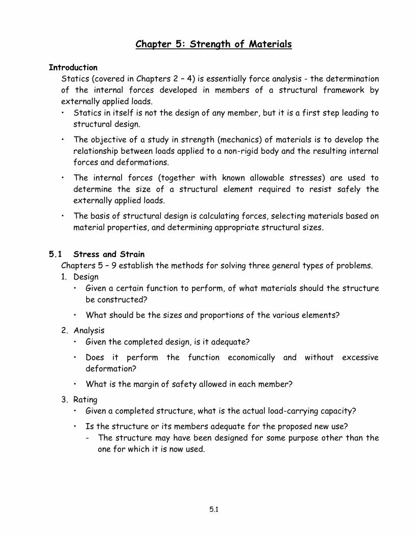
1. Concentrated load
- A load or force that is applied at a point.
- A concentrated load is an idealization.
- Realistically, any load that is applied to a
relatively small area compared with the
size of the loaded member is considered
a concentrated load.
2. Distributed load
- A load distributed along a length or over
an area.
- The load distribution may be uniform or
non-uniform.
5.3
• Loads classified with respect to the location and method of application.
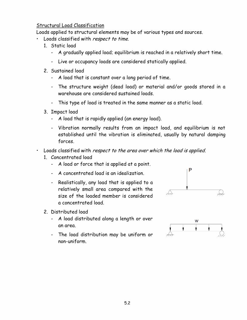
1. Centric (concentric) load
• A load that passes through the centroid
(i.e. geometric center) of the cross
section.
- Force P, shown at the right, has a line
of action that passes through the
centroid of the column and the
footing; therefore, load P is axial.
• The load is called an axial load if the
force passes through the centroids of all
sections.
2. Bending or flexural load
• A load that is applied transversely to the
longitudinal axis of the member.
• The load may include applied couples.
• A member subjected to bending loads
deflects along its length.
The figure above illustrates a beam subjected to flexural load consisting of
a concentrated load, a uniformly distributed load, and a couple.
3. Torsional load
• A load that subjects a member to couples
or moments that twist the member
spirally.
4. Combined loading
• A combination of two or more of the previously defined types of loads.
Concept of Stress
Stress is a term used to describe the intensity of a force.
• Stress is the quantity of force that acts on a unit of area.
• Force, in structural design, has little significance until something is known about
the resisting material, cross-sectional properties, and the size of the element
resisting the force.
5.4
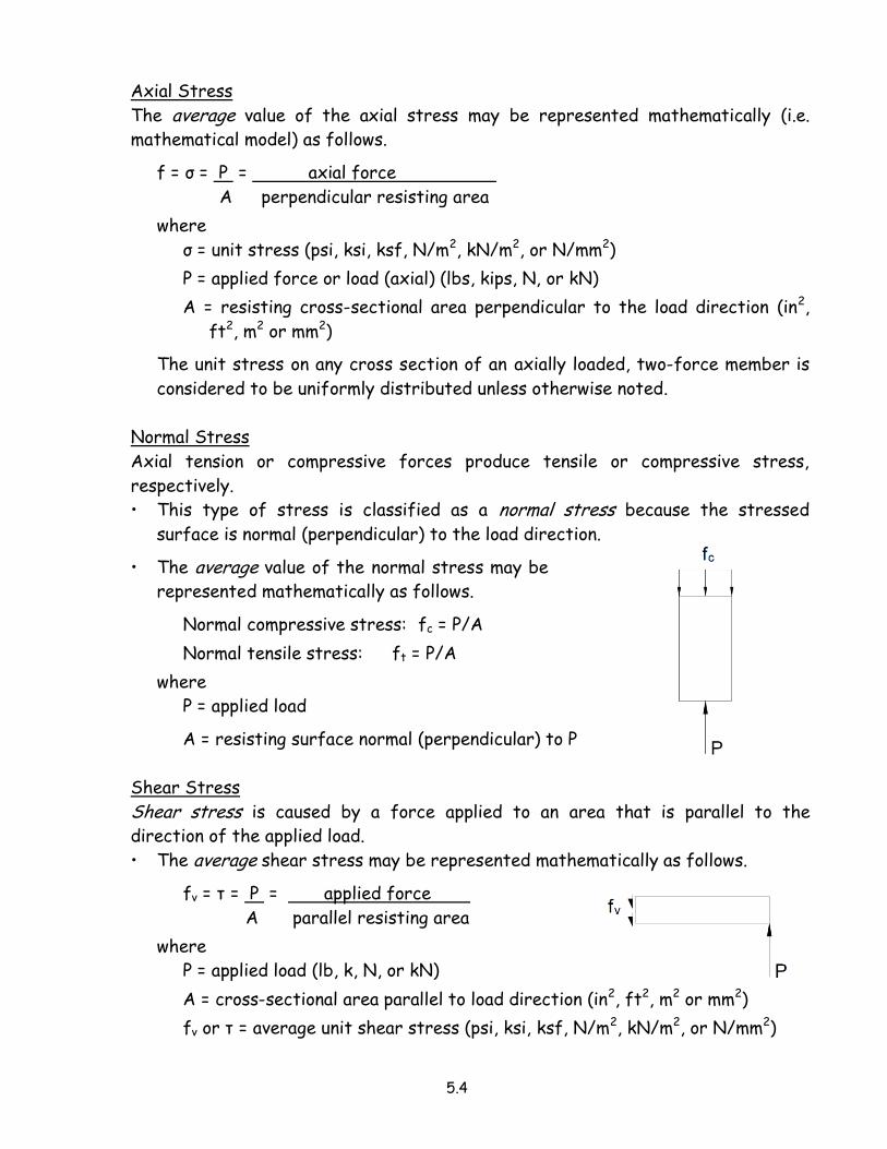
Axial Stress
The average value of the axial stress may be represented mathematically (i.e.
mathematical model) as follows.
f = σ = P = axial force
A perpendicular resisting area
where
σ = unit stress (psi, ksi, ksf, N/m2, kN/m2, or N/mm2)
P = applied force or load (axial) (lbs, kips, N, or kN)
A = resisting cross-sectional area perpendicular to the load direction (in2,
ft2, m2 or mm2)
The unit stress on any cross section of an axially loaded, two-force member is
considered to be uniformly distributed unless otherwise noted.
Normal Stress
Axial tension or compressive forces produce tensile or compressive stress,
respectively.
• This type of stress is classified as a normal stress because the stressed
surface is normal (perpendicular) to the load direction.
• The average value of the normal stress may be
represented mathematically as follows.
Normal compressive stress: fc = P/A
Normal tensile stress: ft = P/A
where
P = applied load
A = resisting surface normal (perpendicular) to P
Shear Stress
Shear stress is caused by a force applied to an area that is parallel to the
direction of the applied load.
• The average shear stress may be represented mathematically as follows.
fv = τ = P = applied force
A parallel resisting area
where
P = applied load (lb, k, N, or kN)
A = cross-sectional area parallel to load direction (in2, ft2, m2 or mm2)
fv or τ = average unit shear stress (psi, ksi, ksf, N/m2, kN/m2, or N/mm2)
5.5
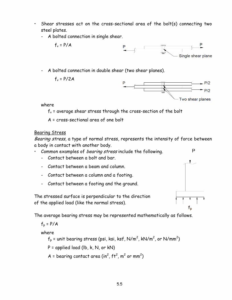
• Shear stresses act on the cross-sectional area of the bolt(s) connecting two
steel plates.
- A bolted connection in single shear.
fv = P/A
- A bolted connection in double shear (two shear planes).
fv = P/2A
where
fv = average shear stress through the cross-section of the bolt
A = cross-sectional area of one bolt
Bearing Stress
Bearing stress, a type of normal stress, represents the intensity of force between
a body in contact with another body.
• Common examples of bearing stress include the following.
- Contact between a bolt and bar.
- Contact between a beam and column.
- Contact between a column and a footing.
- Contact between a footing and the ground.
The stressed surface is perpendicular to the direction
of the applied load (like the normal stress).
The average bearing stress may be represented mathematically as follows.
fp = P/A
where
fp = unit bearing stress (psi, ksi, ksf, N/m2, kN/m2, or N/mm2)
P = applied load (lb, k, N, or kN)
A = bearing contact area (in2, ft2, m2 or mm2)
5.6
In the preceding three stress classifications, the basic equation of stress may be
written in three different ways, depending on the conditions being evaluated.
1. f = P/A
• The basic equation; used for analysis purposes in which the load, member
size, and material are known.
2. P = f x A
• Used in evaluating or checking the capacity of a member when the material
and member size are known.
3. A = P/f
• Design version of the stress equation.
• The member size can be determined if the load and material’s allowable
stress are known.
Torsional stress
Structural members are subjected torsional stress by the twisting along their
longitudinal axis by a moment couple or eccentric load.
• Most building members subjected to torsional effects are also experiencing
either bending, shear, tensile, and/or compressive stresses.
• It is uncommon to design specifically for torsion.
• However, designs involving machinery and motors with shafts are extremely
sensitive to the stresses resulting from torsion.
5.7
Example Problems - Stress
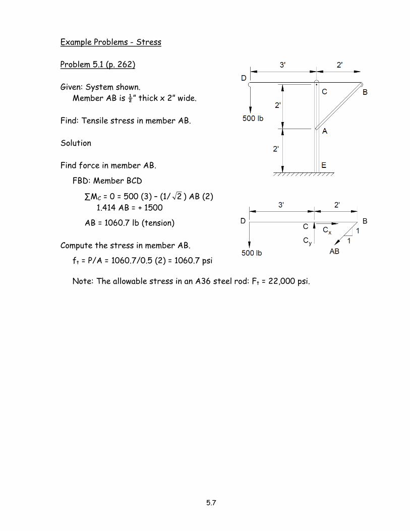
Problem 5.1 (p. 262)
Given: System shown.
Member AB is ½” thick x 2” wide.
Find: Tensile stress in member AB.
Solution
Find force in member AB.
FBD: Member BCD
∑MC = 0 = 500 (3) – (1/ 2 ) AB (2)
1.414 AB = + 1500
AB = 1060.7 lb (tension)
Compute the stress in member AB.
ft = P/A = 1060.7/0.5 (2) = 1060.7 psi
Note: The allowable stress in an A36 steel rod: Ft = 22,000 psi.
5.8
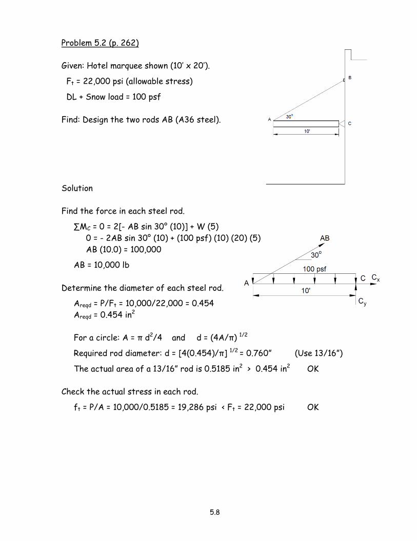
Problem 5.2 (p. 262)
Given: Hotel marquee shown (10’ x 20’).
Ft = 22,000 psi (allowable stress)
DL + Snow load = 100 psf
Find: Design the two rods AB (A36 steel).
Solution
Find the force in each steel rod.
∑MC = 0 = 2[- AB sin 30° (10)] + W (5)
0 = - 2AB sin 30° (10) + (100 psf) (10) (20) (5)
AB (10.0) = 100,000
AB = 10,000 lb
Determine the diameter of each steel rod.
Areqd = P/Ft = 10,000/22,000 = 0.454
Areqd = 0.454 in2
For a circle: A = π d2/4 and d = (4A/π) 1/2
Required rod diameter: d = [4(0.454)/π] 1/2 = 0.760” (Use 13/16”)
The actual area of a 13/16” rod is 0.5185 in2 > 0.454 in2 OK
Check the actual stress in each rod.
ft = P/A = 10,000/0.5185 = 19,286 psi < Ft = 22,000 psi OK
5.9
Deformation and Strain
Most materials of construction deform under the action of loads (i.e. not a true
rigid body).
• When the size or shape of a body is altered, the change in any direction is
termed deformation and given by the symbol δ (delta).
• Strain, ε (epsilon) or γ (gamma), is defined as the deformation per unit length.
• The deformation or strain may be the result of a change of temperature or
stress.
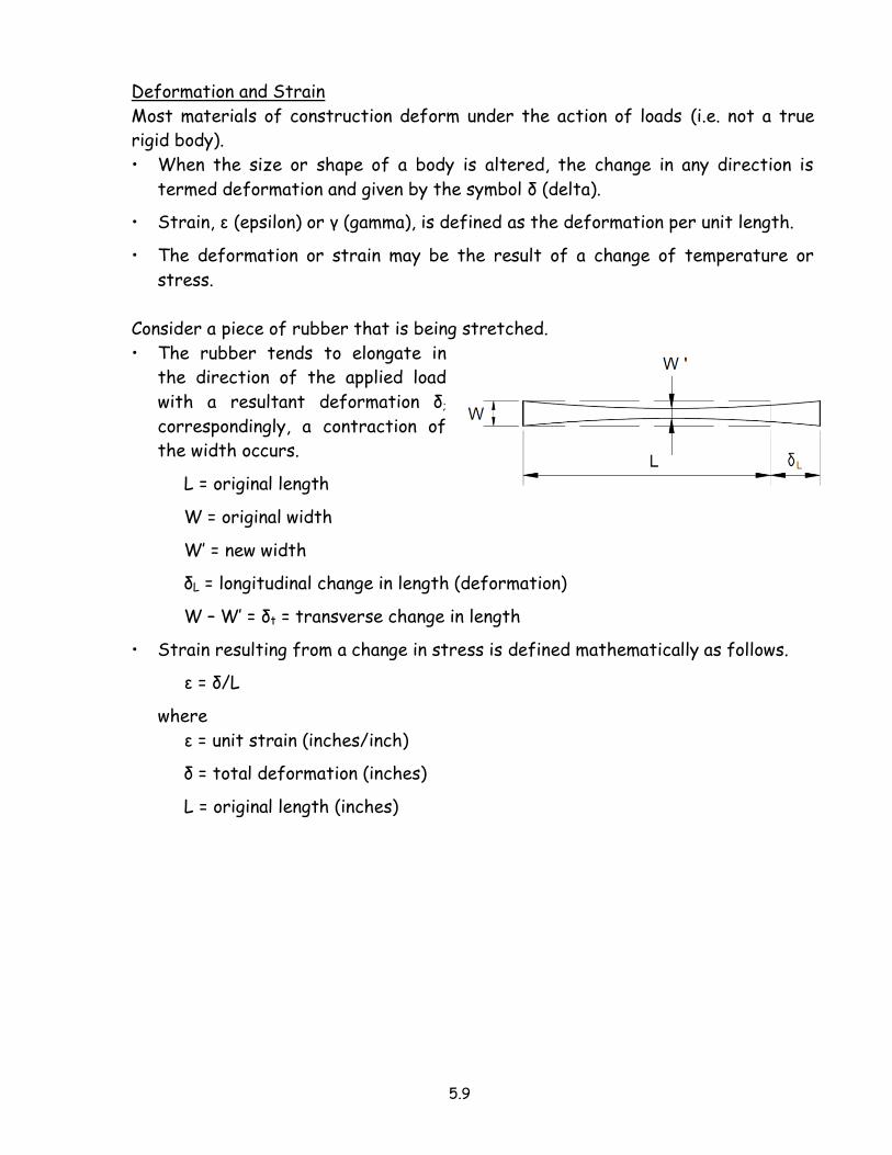
Consider a piece of rubber that is being stretched.
• The rubber tends to elongate in
the direction of the applied load
with a resultant deformation δ;
correspondingly, a contraction of
the width occurs.
L = original length
W = original width
W’ = new width
δL = longitudinal change in length (deformation)
W – W’ = δt = transverse change in length
• Strain resulting from a change in stress is defined mathematically as follows.
ε = δ/L
where
ε = unit strain (inches/inch)
δ = total deformation (inches)
L = original length (inches)
5.10
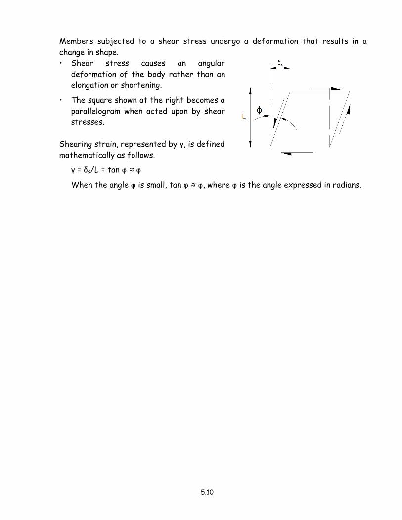
Members subjected to a shear stress undergo a deformation that results in a
change in shape.
• Shear stress causes an angular
deformation of the body rather than an
elongation or shortening.
• The square shown at the right becomes a
parallelogram when acted upon by shear
stresses.
Shearing strain, represented by γ, is defined
mathematically as follows.
γ = δs/L = tan φ ≈ φ
When the angle φ is small, tan φ ≈ φ, where φ is the angle expressed in radians.
5.11
Example Problems - Deformation and Strain
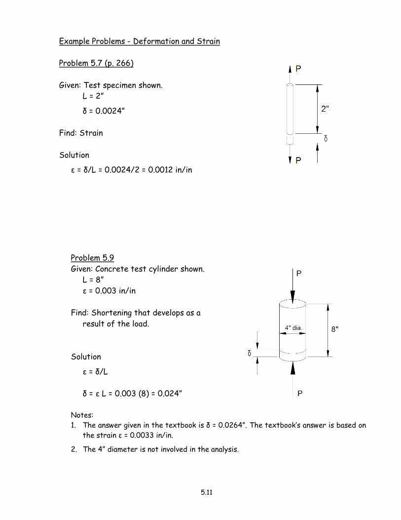
Problem 5.7 (p. 266)
Given: Test specimen shown.
L = 2”
δ = 0.0024”
Find: Strain
Solution
ε = δ/L = 0.0024/2 = 0.0012 in/in
Problem 5.9
Given: Concrete test cylinder shown.
L = 8”
ε = 0.003 in/in
Find: Shortening that develops as a
result of the load.
Solution
ε = δ/L
δ = ε L = 0.003 (8) = 0.024”
Notes:
1. The answer given in the textbook is δ = 0.0264”. The textbook’s answer is based on
the strain ε = 0.0033 in/in.
2. The 4” diameter is not involved in the analysis.
5.12
5.2 Elasticity, Strength, and Deformation
Relationship Between Stress and Strain
A variety of materials is used in architectural structures.
• Materials include stone, brick, concrete, steel, timber, aluminum, and plastics.
• These materials have properties that allow them to be used in a structure.
• A material is selected for use based on its ability to withstand forces without
excessive deformations or actual failures.
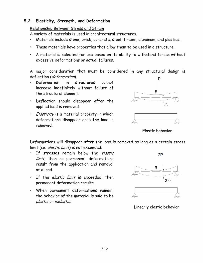
A major consideration that must be considered in any structural design is
deflection (deformation).
• Deformation in structures cannot
increase indefinitely without failure of
the structural element.
• Deflection should disappear after the
applied load is removed.
• Elasticity is a material property in which
deformations disappear once the load is
removed.
Elastic behavior
Deformations will disappear after the load is removed as long as a certain stress
limit (i.e. elastic limit) is not exceeded.
• If stresses remain below the elastic limit, then no permanent deformations
result from the application and removal
of a load.
• If the elastic limit is exceeded, then
permanent deformation results.
• When permanent deformations remain,
the behavior of the material is said to be
plastic or inelastic.
Linearly elastic behavior
5.13
Brittle materials • When the elastic limit is exceeded in brittle materials, the molecular bonds
within the material are unable to reform.
• Cracks form or there is separation of the material.
• Cast iron, high-carbon steel, and ceramics are considered brittle materials.
• Brittle materials give no warning of impending failure.
Ductile materials • When the elastic limit is exceeded in ductile materials, the molecular bonds
reform.
• Permanent deformations result, but the material remains intact without a
significant loss of strength.
• Low-carbon steel, aluminum, copper, and gold are considered ductile materials.
• Ductile materials give warning of impending failure.
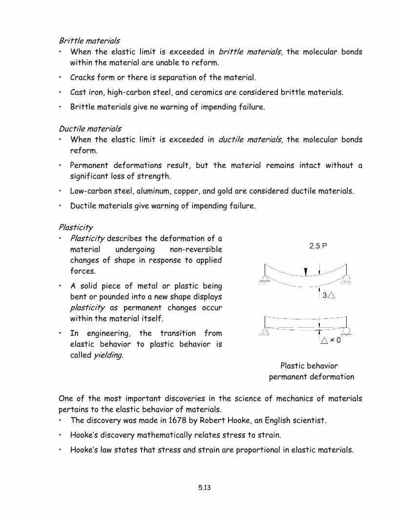
Plasticity • Plasticity describes the deformation of a
material undergoing non-reversible
changes of shape in response to applied
forces.
• A solid piece of metal or plastic being
bent or pounded into a new shape displays
plasticity as permanent changes occur
within the material itself.
• In engineering, the transition from
elastic behavior to plastic behavior is
called yielding.
Plastic behavior
permanent deformation
One of the most important discoveries in the science of mechanics of materials
pertains to the elastic behavior of materials.
• The discovery was made in 1678 by Robert Hooke, an English scientist.
• Hooke’s discovery mathematically relates stress to strain.
• Hooke’s law states that stress and strain are proportional in elastic materials.
5.14
Universal testing machines are used to apply precise loads at precise rates to
standardized tensile and compressive test specimens.
• The tensile test is the most common test.
• Devices are used for measuring and recording strain or deformation.
• The data obtained from the tests are used to plot stress-strain diagrams (or
load-deformation curves).
Figure 5.20 (page 269 of the textbook) shows a stress-strain diagram for various
materials.
• Several characteristic patterns are revealed.
- Ductile rolled steel (ordinary, low-carbon structural steel) follow a straight-
line variation and then deform considerably after the elastic limit is
exceeded.
- Materials such as cast iron, brass, concrete, and wood follow a curved-line
through most of their length and there is no distinct elastic limit.
Stress-strain diagram
• The stress-strain diagram plots strain along the abscissa (horizontal) and
stress along the ordinate (vertical).
• The stress is defined as the load (pounds or kips) divided by the original cross-
sectional area of the test specimen.
As the test proceeds, larger loads are applied at a specified rate.
• The strain determined during the test is based on a test specimen with an
original gauge length of 2” and a diameter of ½”.
• The actual cross-sectional area of the specimen decreases.
• At high stresses, this reduction in the cross-sectional area of the test
specimen becomes significant.
• The calculated stress (called the indicated stress) that is determined during
the test is based on the original cross-sectional area of the test specimen and
is not the true stress.
Figure 5.22 (page 270 of the textbook) shows the stress-strain curve for mild
steel (A36).
• The significant points on the stress-strain curve are defined as follows.
1. Proportional limit
5.15
- The proportional limit is the limit of the linear variation of stress and
strain.
- Hooke’s law of stress-strain proportionality is no longer valid when
stresses exceed this limit.
2. Elastic limit
- The elastic limit is close to the proportional limit.
- The elastic limit is the maximum stress that can be developed in a
material without causing a permanent set (deformation).
- A specimen stressed to a point below its elastic limit will return to its
original dimensions when the load is released.
- If the stress should exceed the elastic limit, the specimen will deform
plastically and will not return to its original dimensions when the load is
released. The material is said to have a permanent set.
3. Yield point
- The yield point is the stress at which strain (or deformation) continues to
increase without an increase in the applied load.
- After the initial yielding (upper yield point) is reached, the force
resisting deformation actually decreases due to the yielding of the
material.
- The value of stress after the initial yield point (known as the lower yield point) is usually used as the basis for determining the allowable stress
that is used for design purposes.
Some materials (such as cast iron) do not exhibit a well-defined yield point.
- The yield strength is defined as the stress at which the material exhibits
a specified limiting permanent set.
- The specified set (or offset) most commonly used is 0.2%, which
corresponds to a strain of 0.002 in/in.
4. Ultimate strength
- The ultimate strength (stress) of a material is the maximum load (i.e. the
load reached when the specimen breaks) divided by the original cross-
sectional area.
- The ultimate strength (a.k.a. the tensile strength) of a material is
sometimes used as a basis for establishing the allowable design stresses.
5.16
5. Rupture strength
- Rupture strength is the breaking strength, or fracture strength of the
material.
- In a ductile material, rupture does not usually occur at the ultimate
stress.
◦ After the ultimate stress has been reached, the material will
generally neck down, and its rapidly increasing elongation will be
accompanied by a decrease in load.
- The rupture strength, is determined by dividing the load at rupture by
the original cross-sectional area of the specimen.
- Rupture strength has little or no value in design.
6. Reduction of area.
- As the load on the tested material is increased, the original cross-
sectional area decreases to a minimum at the instant of fracture.
◦ The failed specimen exhibits a local decrease in diameter known as
necking down in the region where the failure occurs.
◦ Ductile materials exhibit a high reduction in area; brittle materials
exhibit almost no reduction in area.
- The true value of stress, following the ultimate stress, is determined by
dividing the loads by the actual (decreasing) cross-sectional areas.
5.3 Other Material Properties
Compression Tests
• The compression test is used primarily to test brittle materials such as cast
iron and concrete.
• The results of the compression test generally define an elastic range, a
proportional limit, and a yield strength.
• In the compression test, the cross-sectional area of the specimen increases as
the load increases.
Poisson’s Ratio
When a material is loaded in one direction, it will undergo strains perpendicular to
the direction of the load as well as parallel to it.
• The ratio of the lateral (perpendicular) strain to the longitudinal (axial) strain
is called Poisson’s ratio.
5.17
• Poisson’s ratio varies from 0.2 to 0.4 for most metals.
- Most steels have values in the range of 0.283 to 0.292.
• The symbol μ (mu) is used for Poisson’s ratio, which is given by the equation.
μ = εlateral/εlongitudinal
Allowable Stress - Factor of Safety
An allowable stress is defined as the maximum stress that is permitted in a design
calculation.
• The allowable stress for A36 steel (Fy = 36 ksi) in tension is expressed as
follows.
Ft = 22.0 ksi
The factor of safety is defined as the ratio of a failure-producing load to the
estimated actual load.
F.S. = Failure load/Actual load
Modulus of Elasticity (Young’sModulus)
In 1678 Sir Robert Hooke observed that stress is proportional to strain.
In 1807 Thomas Young suggested that this modulus (ratio) could be used as a
means of evaluating the stiffness of materials.
• The modulus of elasticity (called Young’s modulus) is found by dividing stress by
strain.
• This ratio is the slope of the straight-line portion of the stress-strain diagram
and is expressed mathematically as follows.
E = f/ε
where
E = modulus of elasticity (ksi, psi, N/mm2)
f = stress (ksi, psi, N/mm2)
ε = strain (in/in, mm/mm)
This ratio of stress to strain is constant for all steels and many other structural
materials (e.g. E = 29,000 ksi for steel).
• A high modulus of elasticity is desirable for structural materials.
- E is often referred to as a stiffness factor.
5.18
• Materials exhibiting high E values are more resistant to deformation.
- In the case of beams, the higher the E value, the less the deflection under
load.
The equation for Young’s modulus may be written in the following form whenever
the stress and deformation are caused by axial loads.
From previous work: f = P/A and ε = δ/L
E = f/ε = P/A = PL
δ/L δA
From the equation for Young’s modulus, the equation for deformation due to
axial loads is formulated.
δ = PL/AE (elastic equation)
where
δ = deformation (in, mm)
P = applied axial load (lb, kips, N, or kN)
L = length of member (in, mm)
A = cross-sectional area of member (in2, mm2)
E = modulus of elasticity of material (psi, ksi, N/mm2)
5.19
Example Problems - Material Properties
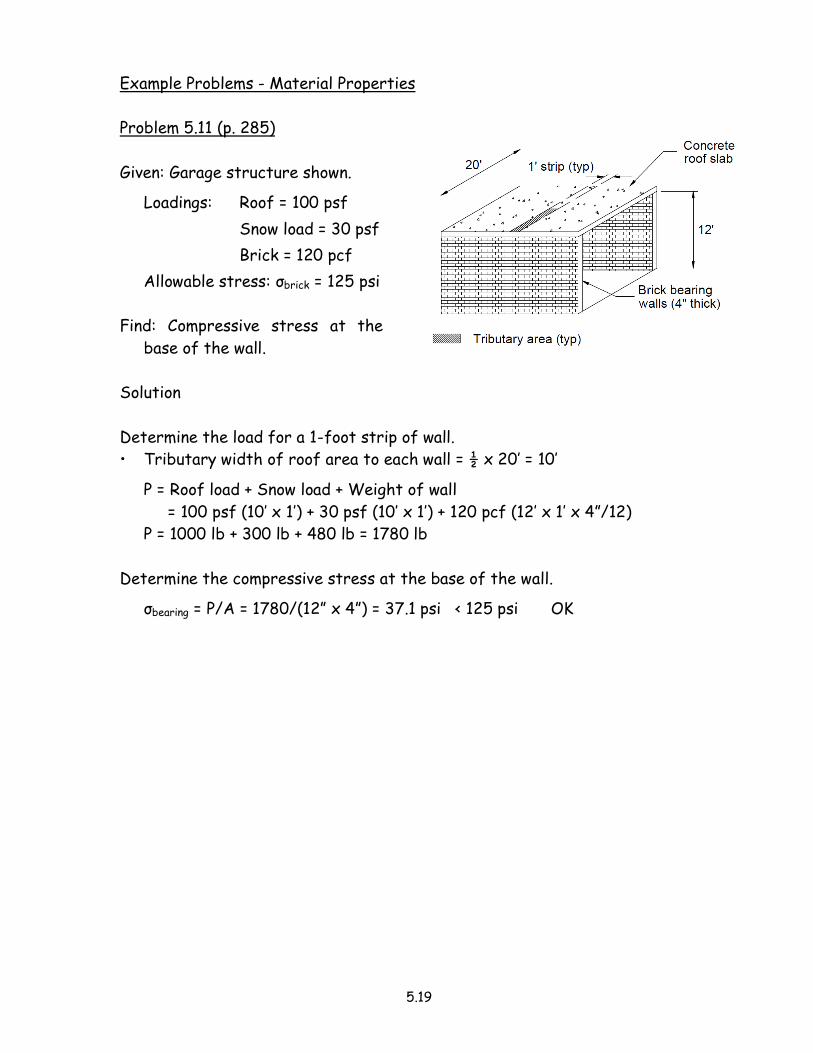
Problem 5.11 (p. 285)
Given: Garage structure shown.
Loadings: Roof = 100 psf
Snow load = 30 psf
Brick = 120 pcf
Allowable stress: σbrick = 125 psi
Find: Compressive stress at the
base of the wall.
Solution
Determine the load for a 1-foot strip of wall.
• Tributary width of roof area to each wall = ½ x 20’ = 10’
P = Roof load + Snow load + Weight of wall
= 100 psf (10’ x 1’) + 30 psf (10’ x 1’) + 120 pcf (12’ x 1’ x 4”/12)
P = 1000 lb + 300 lb + 480 lb = 1780 lb
Determine the compressive stress at the base of the wall.
σbearing = P/A = 1780/(12” x 4”) = 37.1 psi < 125 psi OK
5.20
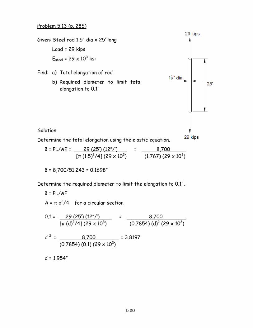
Problem 5.13 (p. 285)
Given: Steel rod 1.5” dia x 25’ long
Load = 29 kips
Esteel = 29 x 103 ksi
Find: a) Total elongation of rod
b) Required diameter to limit total
elongation to 0.1”
Solution
Determine the total elongation using the elastic equation.
δ = PL/AE = 29 (25’) (12”/’) = 8,700
[π (1.5)2/4] (29 x 103) (1.767) (29 x 103)
δ = 8,700/51,243 = 0.1698”
Determine the required diameter to limit the elongation to 0.1”.
δ = PL/AE
A = π d2/4 for a circular section
0.1 = 29 (25’) (12”/’) = 8,700
[π (d)2/4] (29 x 103) (0.7854) (d)2 (29 x 103)
d 2 = 8,700 = 3.8197
(0.7854) (0.1) (29 x 103)
d = 1.954”
5.21
Stress Concentrations
Stress is generally considered as uniformly distributed on any cross-section of the
member.
• We assume that a load is applied centrically (i.e. through the axis of the
member).
• Generally, this is a practical assumption to make for a static load condition.
However, stress cannot be considered as uniformly distributed in the following
cases.
• The geometry of the member changes to include discontinuities or changing
cross sections.
• Load concentrations (e.g. corners, notches, openings, and other discontinuities)
will cause stress concentrations.
Load concentrations do not necessarily produce structural failures, even if the
maximum stress exceeds the allowable working stress.
• In structural steel, extreme stress conditions may be relieved because steel is
ductile and has a tendency to yield (give).
- The stress is redistributed over more of the cross-sectional area.
- The redistribution of stress enables the greater part of the structural
member to be within permissible stress range.
• In concrete, a stress concentration is a serious matter.
- Excessive tensile stresses, even though localized, cause cracks to appear in
the concrete.
- Over time, the cracks become more pronounced because of the high stress
concentration at the end of the cracks.
- Cracking in reinforced concrete can be minimized by placing the reinforcing
steel across potential crack lines.
• In timber, stress concentrations cause cracks to appear along the grain.
In statically loaded ductile materials, stress concentrations are usually not critical.
• The material will yield inelastically in the high-stress areas.
• Redistribution of stress results.
• Equilibrium is established and no harm is done.
5.22
In dynamic or impact loading of ductile materials, or static loading of brittle
materials stress concentrations become critical.
• Stress concentrations become very critical and cannot be ignored.
• Stress redistribution does not result to such an extent that equilibrium is
maintained.
Torsional Stress
Charles-Augustin de Coulomb, a French engineer of the 18th century:
• He was the first to explain torsion in a solid or hollow circular shaft.
• He developed a relationship between the applied torque (T) and the resulting
deformation (angle of twist) of circular rods.
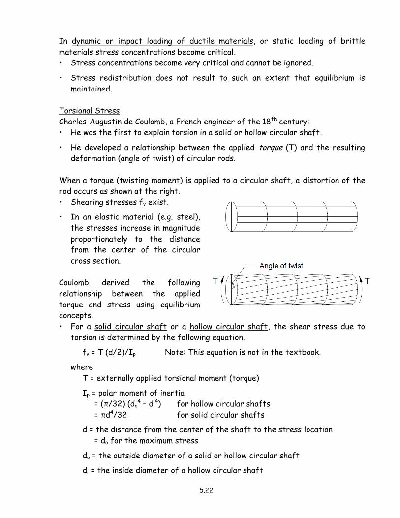
When a torque (twisting moment) is applied to a circular shaft, a distortion of the
rod occurs as shown at the right.
• Shearing stresses fv exist.
• In an elastic material (e.g. steel),
the stresses increase in magnitude
proportionately to the distance
from the center of the circular
cross section.
Coulomb derived the following
relationship between the applied
torque and stress using equilibrium
concepts.
• For a solid circular shaft or a hollow circular shaft, the shear stress due to
torsion is determined by the following equation.
fv = T (d/2)/Ip Note: This equation is not in the textbook.
where
T = externally applied torsional moment (torque)
Ip = polar moment of inertia
= (π/32) (do4 – di
4) for hollow circular shafts
= πd4/32 for solid circular shafts
d = the distance from the center of the shaft to the stress location
= do for the maximum stress
do = the outside diameter of a solid or hollow circular shaft
di = the inside diameter of a hollow circular shaft
5.23
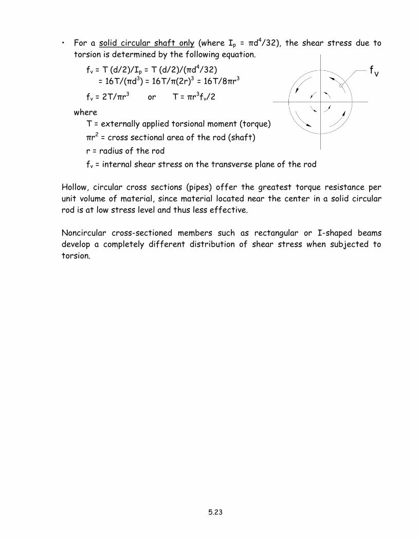
• For a solid circular shaft only (where Ip = πd4/32), the shear stress due to
torsion is determined by the following equation.
fv = T (d/2)/Ip = T (d/2)/(πd4/32)
= 16T/(πd3) = 16T/π(2r)3 = 16T/8πr3
fv = 2T/πr3 or T = πr3fv/2
where
T = externally applied torsional moment (torque)
πr2 = cross sectional area of the rod (shaft)
r = radius of the rod
fv = internal shear stress on the transverse plane of the rod
Hollow, circular cross sections (pipes) offer the greatest torque resistance per
unit volume of material, since material located near the center in a solid circular
rod is at low stress level and thus less effective.
Noncircular cross-sectioned members such as rectangular or I-shaped beams
develop a completely different distribution of shear stress when subjected to
torsion.
5.24
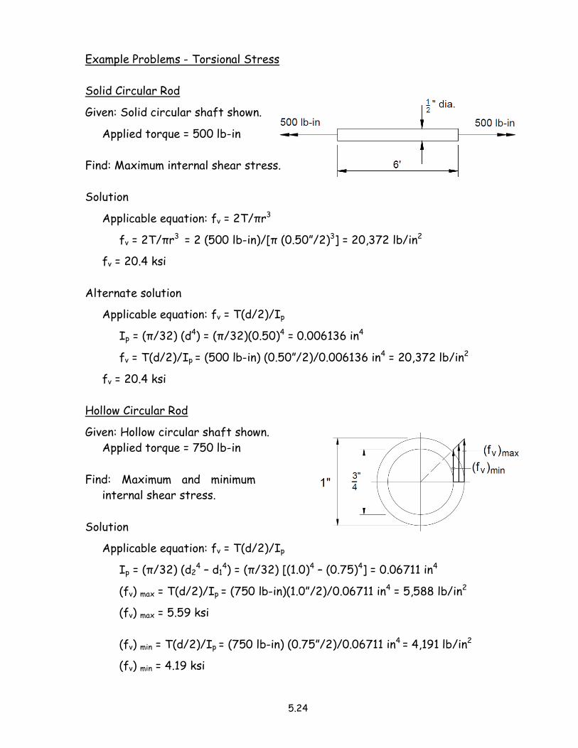
Example Problems - Torsional Stress
Solid Circular Rod
Given: Solid circular shaft shown.
Applied torque = 500 lb-in
Find: Maximum internal shear stress.
Solution
Applicable equation: fv = 2T/πr3
fv = 2T/πr3 = 2 (500 lb-in)/[π (0.50”/2)3] = 20,372 lb/in2
fv = 20.4 ksi
Alternate solution
Applicable equation: fv = T(d/2)/Ip
Ip = (π/32) (d4) = (π/32)(0.50)4 = 0.006136 in4
fv = T(d/2)/Ip = (500 lb-in) (0.50”/2)/0.006136 in4 = 20,372 lb/in2
fv = 20.4 ksi
Hollow Circular Rod
Given: Hollow circular shaft shown.
Applied torque = 750 lb-in
Find: Maximum and minimum
internal shear stress.
Solution
Applicable equation: fv = T(d/2)/Ip
Ip = (π/32) (d24 – d1
4) = (π/32) [(1.0)4 – (0.75)4] = 0.06711 in4
(fv) max = T(d/2)/Ip = (750 lb-in)(1.0”/2)/0.06711 in4 = 5,588 lb/in2
(fv) max = 5.59 ksi
(fv) min = T(d/2)/Ip = (750 lb-in) (0.75”/2)/0.06711 in4 = 4,191 lb/in2
(fv) min = 4.19 ksi
5.25
5.4 Thermal Effects
Most structural materials increase in volume when subjected to heat and contract
when cooled.
• Whenever a design (i.e. a support or connection) prevents the change in length
of a member subjected to temperature variation, internal stresses develop.
• These thermal stresses may be sufficiently high to exceed the elastic limit of
the material and may cause serious damage.
• Free, unrestrained members experience no stress changes with temperature
changes, but dimensional changes result.
The dimensional change due to temperature changes is usually described in terms
of change in a linear dimension.
• The change in length of a structural member, ΔL, is proportional to both
temperature change (ΔT) and the original length of the member Lo.
• Thermal sensitivity (i.e. the coefficient of linear expansion, α) has been
determined for all engineering materials.
• Careful measurements show that the thermal sensitivity, α, is equal to the ratio
of strain ε to temperature change ΔT.
• Thermal sensitivity is a constant value for a given material.
α = Strain/Temperature change = ε/ΔT = (δ/L)/ΔT
Solve this equation for the deformation.
δ = α L ΔT
where
α = coefficient of thermal expansion
L = original length of member (inches)
ΔT = change in temperature (°F)
δ = total change in length (inches)
Stresses are developed by restraining the free expansion and contraction of
members subjected to temperature variations.
• To calculate these thermal stresses, first, determine the free expansion or
contraction of the member.
δ = α L ΔT
5.26
• Then, determine the force and unit stress developed in forcing the member to
attain its original length.
δ = PL/AE = f L/E
The problem from this point on is the same as those solved in the earlier portions
of this chapter dealing with axial stresses, strains, and deformations.
• The stress developed by restoring a bar to its original length L may be
determined by the following equation.
f = ε E = (δ/L) E = (α L ΔT/L) E
f = α ΔT E
• Alternatively, the equation may be developed by equating the deformation due
to temperature change with the deformation due to the axial load.
δ = α L ΔT deformation due to temperature change
δ = f L/E deformation due to axial load
Then, α L ΔT = f L/E
and f = α L ΔT (E/L) = α ΔT E
5.27
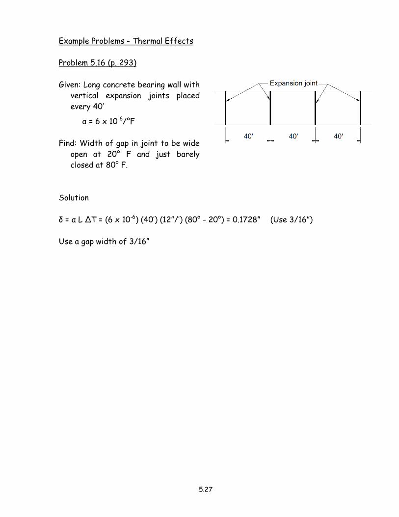
Example Problems - Thermal Effects
Problem 5.16 (p. 293)
Given: Long concrete bearing wall with
vertical expansion joints placed
every 40’
α = 6 x 10⁻⁶/°F
Find: Width of gap in joint to be wide
open at 20° F and just barely
closed at 80° F.
Solution
δ = α L ΔT = (6 x 10⁻⁶) (40’) (12”/’) (80° - 20°) = 0.1728” (Use 3/16”)
Use a gap width of 3/16”
5.28
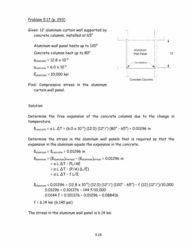
Problem 5.17 (p. 293)
Given: 12’ aluminum curtain wall supported by
concrete columns, installed at 65°
Aluminum wall panel heats up to 120°
Concrete columns heat up to 80°
αaluminum = 12.8 x 10⁻⁶
αconcrete = 6.0 x 10⁻⁶
Ealuminum = 10,000 ksi
Find: Compressive stress in the aluminum
curtain wall panel.
Solution
Determine the free expansion of the concrete columns due to the change in
temperature.
δconcrete = α L ΔT = (6.0 x 10⁻⁶) (12.0) (12”/’) (80° - 65°) = 0.01296 in
Determine the stress in the aluminum wall panels that is required so that the
expansion in the aluminum equals the expansion in the concrete.
δaluminum = δconcrete = 0.01296 in
δaluminum = (δaluminum)thermal – (δaluminum)stress = 0.01296 in
= α L ΔT – PL/AE
= α L ΔT - (P/A) (L/E)
= α L ΔT - f L/E
δaluminum = 0.01296 = (12.8 x 10⁻⁶) (12.0) (12”/’) (120° - 65°) – f (12) (12”/’)/10,000
0.01296 = 0.101376 – 144 f/10,000
0.0144 f = 0.101376 – 0.01296 = 0.088416
f = 6.14 ksi (6,140 psi)
The stress in the aluminum wall panel is 6.14 ksi.
5.29
5.5 Statically Indeterminate Members (Axially Loaded)
So far, it has always been possible to find the internal forces in any member of a
structure by means of the equations of equilibrium (i.e. the structures were
statically determinate).
• If, in any structure, the number of unknown forces exceeds the number of
independent equations of equilibrium that are applicable, the structure is said
to be “statically indeterminate.”
• If a structure is statically indeterminate, it is necessary to write additional
equations involving the geometry of the deformations (a.k.a. boundary
conditions) in the members of the structure.
5.30
Example Problem - Statically Indeterminate Members (Axially Loaded)
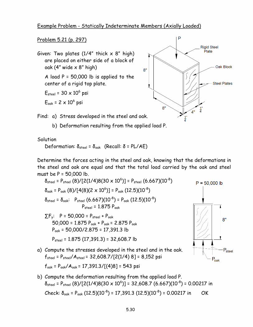
Problem 5.21 (p. 297)
Given: Two plates (1/4” thick x 8” high)
are placed on either side of a block of
oak (4” wide x 8” high)
A load P = 50,000 lb is applied to the
center of a rigid top plate.
Esteel = 30 x 106 psi
Eoak = 2 x 10⁶ psi
Find: a) Stress developed in the steel and oak.
b) Deformation resulting from the applied load P.
Solution
Deformation: δsteel = δoak (Recall: δ = PL/AE)
Determine the forces acting in the steel and oak, knowing that the deformations in
the steel and oak are equal and that the total load carried by the oak and steel
must be P = 50,000 lb.
δsteel = Psteel (8)/[2(1/4)8(30 x 106)] = Psteel (6.667)(10-8)
δoak = Poak (8)/[4(8)(2 x 106)] = Poak (12.5)(10-8)
δsteel = δoak: Psteel (6.667)(10-8) = Poak (12.5)(10-8)
Psteel = 1.875 Poak
∑Fy: P = 50,000 = Psteel + Poak
50,000 = 1.875 Poak + Poak = 2.875 Poak
Poak = 50,000/2.875 = 17,391.3 lb
Psteel = 1.875 (17,391.3) = 32,608.7 lb
a) Compute the stresses developed in the steel and in the oak.
fsteel = Psteel/Asteel = 32,608.7/[2(1/4) 8] = 8,152 psi
foak = Poak/Aoak = 17,391.3/[(4)8] = 543 psi
b) Compute the deformation resulting from the applied load P.
δsteel = Psteel (8)/[2(1/4)8(30 x 106)] = 32,608.7 (6.667)(10-8) = 0.00217 in
Check: δoak = Poak (12.5)(10-8) = 17,391.3 (12.5)(10-8) = 0.00217 in OK