Embed Size (px)
Citation preview

DRIVE SYSTEM-IVT
29
There are two drive systems available for the I-series tractor. One system uses two HydroGear trans-missions. The other system uses an Infinitrak full-toroi-dal Infinitely Variable Transmission (IVT). This chapter will cover the IVT version of the tractor.
The Infinitrak full-toroidal Infinitely Variable Trans-mission (IVT) removes the constraints of conventional stepped ratio transmissions. Instead of using a system of gears to determine the ratio range, the IVT uses a variator that is made of a set of discs and rollers called a “full toroidal” variator. In the IVT, the torque is con-trolled allowing optimization of the power train by allow-ing the engine to run at its most efficient RPM range and stay there.
The IVT used on the I-series is a twin variator ver-sion. This means that there is one input and two out-puts. See Figure 5B.1
Figure 5B.1
“T” box Input shaft
Variators
The power from the engine is transferred to the transmission via a belt and pulleys. The power is applied to a “T” box assembly. The “T” box output drives the inner discs of the variator assemblies. See Figure 5B.2
Each inner disc drives a pair of rollers that drive the output discs. The angle of the rollers determines the speed of the output discs. When the rollers rides near the center of the input discs, they are pressing against the outer edge of the output discs. In this position, the output disc will be turning at a much slower rate than the input discs. See Figure 5B.3
Figure 5B.2
“T” box assembly
Inner disks
Figure 5B.3
Input discs
Rollers
Output disc
500 rpm
50 rpm
CHAPTER 5B: DRIVE SYSTEM - IVT TRANSMISSION
DRIVE SYSTEM-IVT
30
NOTE: The RPM numbers used in figures 5B.2, 5B.3 and 5B.4 are not the actual measurements of the disc speeds. They are just an example to demonstrate the speed differences.
When the rollers rides near the outer edge of the input discs, they are pressing against the center of the output discs. In this position, the output disc will be turning at a much faster rate than the input discs. See Figure 5B.4
When the rollers are in the neutral position or in the center of the disc valley, all of the discs are rotating at the same speed. See Figure 5B.5
The key to making this work is a special traction fluid that was developed for this transmission. A Trac-tion fluid is a synthetic transmission fluid designed with properties specifically for transmitting torque between the discs and rollers.
Under normal load conditions this fluid acts like a conventional lubricating fluid. When the fluid is sub-jected to extreme pressure, such as in the contact area between the discs and rollers, the fluid changes to exhibit its ElastoHydrodynamic Lubricant (EHL) proper-ties. The EHL property of the traction fluid causes the molecules in the fluid to become almost solid. This increases the shear force transmitting properties of the fluid.
The traction fluid in the contact area between the rollers and discs turns into a semi-solid. This allows the fluid to act like a gear tooth, transferring the torque from the disc to the roller or vise versa. It also prevents metal to metal contact extending the life of the moving parts.
NOTE: Putting motor oil or hydraulic fluid in an IVT transmission will destroy it.
Each of the variators are attached to a epicyclic, also know as planetary, gear set. See Figure 5B.6
Figure 5B.4
500 rpm1,000 rpm
Figure 5B.5
500 rpm
Figure 5B.6
Epicyclic gear sets

DRIVE SYSTEM-IVT
31
The output shaft of the T-box drives a sun gear in the center of the planetary gears at the same speed as the input discs. The planetary gear carriers are attached to the output discs. See Figure 5B.7
The epicyclic gear set acts like an adding machine, it subtracts the input (sun gear) speed from the output (planetary gear carrier). See Figure 5B.8
Figure 5B.7
Output disk
Epicyclic gear set
Carrier
Planetary gears
Figure 5B.8
Planetary gear
Sun gear
Carrier
If the answer is positive, transmission drives in a forward direction. If the answer is negative, the trans-mission drives in reverse. If the answer is zero, the transmission will have zero output and be in what is known as a geared neutral state. See Figure 5B.9
The answers from the epicyclic gear sets are col-lected by the transmission output shafts that are driven b the planetary gears. See Figure 5B.10
Figure 5B.9
Figure 5B.10
Output shaft

DRIVE SYSTEM-IVT
32
The transmission output shafts drive a pair of drop axles assemblies.
The IVT transmissions are NOT serviceable. The drop axles and brakes are serviceable and will be covered in later sections of this chapter.
NOTE: Currently replacement traction fluid is not available for purchase.
Drive belt
The drive belt is the most common drive system component that will need attention. To remove/replace the drive belt:
1. Remove the deck as described in chapter 8: Cutting Decks and Lift Shaft.
2. Lift and safely support the rear of the tractor.
3. Remove the three belt guides near the idler pul-leys. See Figure 5B.11
Cub Cadet belts are design to fit our equipment and are not stan-dard lengths. Use of a non-OEM
belt may prevent the de-clutching mechanism from working properly when the brakes are applied.
! CAUTION! CAUTION
Figure 5B.11
Belt Guides

DRIVE SYSTEM-IVT
33
4. Slide the retainer clip half way out of the damp-ener end using small flat head screw driver. See Figure 5B.12
5. Disconnect the dampener from the moveable idler pulley bracket.
6. Disconnect the brake link from the moveable idler pulley bracket.
7. Loosen the moveable idler pulley enough for the belt to slip past the belt guide using a pair of 9/16” wrenches. See Figure 5B.13
8. Slip the belt off of the idler pulleys.
Figure 5B.12
Retainer clip
Dampener endMoveable idler
Figure 5B.13
Belt guide
9. Unplug the electric PTO harness. See Figure 5B.14
10. Unbolt the electric PTO using an impact wrench and a 5/8” socket. See Figure 5B.15
NOTE: If the PTO clutch will not slide off of the crankshaft, thread the bolt half way into the crankshaft. Make sure the belt keeper is in place to prevent the clutch from rotating. Plug in the PTO clutch harness. Start the engine and turn the PTO on and off several times to shake it loose.
Figure 5B.14
Starter
PTO connector
Figure 5B.15
Remove bolt with an impact wrench
PTO clutch

DRIVE SYSTEM-IVT
34
11. Slide the engine pulley down far enough to slip the belt off of the pulley. See Figure 5B.16
NOTE: If the engine pulley will not slide down the crankshaft using the steps above, remove the engine mounting bolts and slide the engine back. This will give enough clearance to slide the belt off of the engine pulley.NOTE: Note the direction of the key in the engine pulley. It should be facing down. If the pulley is installed upside down, the belt align-ment will be off.NOTE: When installing the engine pulley and electric PTO, coat the crankshaft with anti-seize. This will ease pulley and clutch removal in the future.NOTE: There is a spacer above the engine pul-ley. It is symmetrical and can not be put on upside down. See Figure 5B.17
12. Remove the rear wheels.
13. Remove the transmission fan.
13a. Reach in through the wheel opening.
13b. Remove the three transmission fan screws using a 5/16” wrench. See Figure 5B.18
13c. Remove the transmission fan.
NOTE: Never use an impact wrench to remove the transmission pulley. It will destroy the one way bearing on the input shaft.
14. Remove the transmission belt guard.
14a. Remove the four screws using a 5/16” wrench. See Figure 5B.19
14b. Remove the belt guard.
Figure 5B.16
Engine pulley
Figure 5B.17
Spacer
Engine pulley
Figure 5B.18
Transmission fan
Figure 5B.19
Belt guard
DRIVE SYSTEM-IVT
35
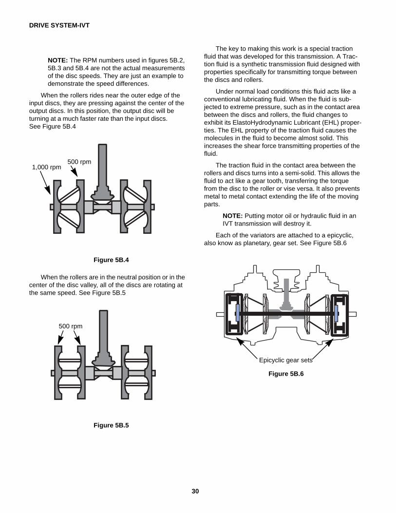
15. Slip the belt off of the transmission pulley.
16. Remove the belt from the tractor.
17. Install the belt following the previous steps in reverse order.
NOTE: Tighten the electric PTO clutch bolt to a torque of 450 - 600 in-lbs (51 - 68 Nm).
18. Test drive the tractor before returning to service.
Figure 5B.20
Drive belt routing
Belt adjustment
The drive belt is tensioned by a spring loaded moveable idler pulley. When the brakes are applied, the drive belt is de-clutched. An adjustable linkage con-nects the tensioner pulley to the brake shaft. A brake link that is out of adjustment will prevent the moveable idler from correctly tensioning and de-tensioning the belt.
As the belt wears and stretches, the moveable idler needs to push the belt in further to keep proper belt tension. To do this, the ferrule at the end of the brake link needs to be at the rear of the slot in the idler pulley bracket.
NOTE: The moveable idler pulley has a damp-ener on it. The dampener allows a slow, smooth engagement of the drive belt. See Figure 5B.21
The brake link is adjusted to the rear of the slot in the moveable idler bracket. This allows the brake pedal can return rapidly when the pedal is released, while the dampener slows the engagement of the drive belt.
To adjust this brake link:
NOTE: The belt must be on when performing this adjustment.
1. Release the parking brake.
2. Remove the deck as described in chapter 8 Cut-ting Decks and Lift Shaft.
Figure 5B.21
Dampener
Moveableidlerpulley
Brake link
Operating the tractor with the idler pulley dampener removed will result in the tractor lurching when
the brake pedal is released.
! CAUTION! CAUTION
DRIVE SYSTEM-IVT
36
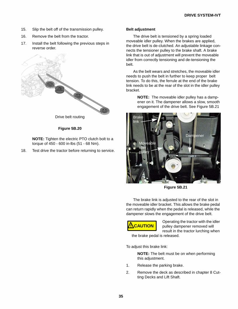
3. Remove the cotter pin and washer from the fer-rule. See Figure 5B.22
4. Slide the ferrule out of the idler bracket. See Figure 5B.23
5. Adjust the ferrule so that it lines up with the rear of the slot and slides in without pulling on the spring.
6. Install the washer and a new cotter pin.
7. Re-attach the deck.
8. Test drive the tractor before returning to service.
Transmissions
To remove the transmission:
1. Remove the deck as described in chapter 8 Cut-ting Decks and Lift Shaft.
2. Lift and safely support the rear of the tractor.
3. Remove the dash and fender by following the steps described in Chapter 4: Body/Chassis.
4. Remove the rear wheels.
5. Remove the drive belt from the engine pulley and the idler pulleys by following the procedures described in the drive belt section of this chapter.
NOTE: The belt can stay on the transmission pulley while the transmission is removed.
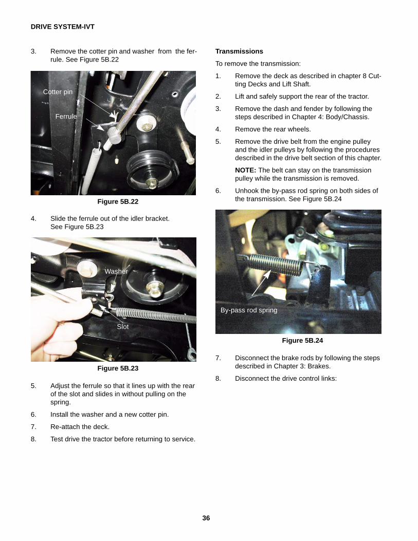
6. Unhook the by-pass rod spring on both sides of the transmission. See Figure 5B.24
7. Disconnect the brake rods by following the steps described in Chapter 3: Brakes.
8. Disconnect the drive control links:
Figure 5B.22
Ferrule
Cotter pin
Figure 5B.23
Washer
Slot
Figure 5B.24
By-pass rod spring
DRIVE SYSTEM-IVT
37
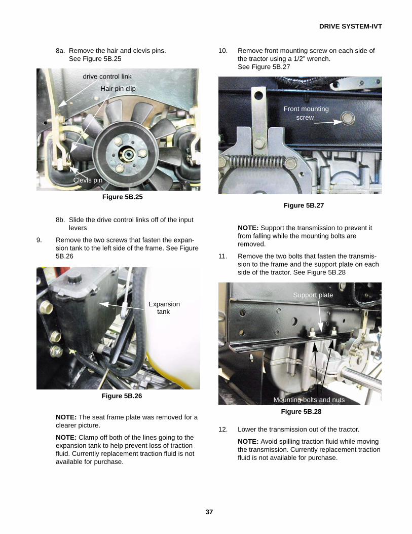
8a. Remove the hair and clevis pins. See Figure 5B.25
8b. Slide the drive control links off of the input levers
9. Remove the two screws that fasten the expan-sion tank to the left side of the frame. See Figure 5B.26
NOTE: The seat frame plate was removed for a clearer picture.
NOTE: Clamp off both of the lines going to the expansion tank to help prevent loss of traction fluid. Currently replacement traction fluid is not available for purchase.
Figure 5B.25
Clevis pin
Hair pin clip
drive control link
Figure 5B.26
Expansiontank
10. Remove front mounting screw on each side of the tractor using a 1/2” wrench. See Figure 5B.27
NOTE: Support the transmission to prevent it from falling while the mounting bolts are removed.
11. Remove the two bolts that fasten the transmis-sion to the frame and the support plate on each side of the tractor. See Figure 5B.28
12. Lower the transmission out of the tractor.
NOTE: Avoid spilling traction fluid while moving the transmission. Currently replacement traction fluid is not available for purchase.
Figure 5B.27
Front mounting screw
Figure 5B.28
Support plate
Mounting bolts and nuts

DRIVE SYSTEM-IVT
38
13. If replacing the transmission assembly, remove the transmission fan.
14. If only replacing the IVT (center section of the transmission), remove the drop axles by follow-ing the procedures described in the drop axle section of this manual.
15. Install the transmission by following the previous steps in reverse order.
16. Perform a neutral adjustment and wheel align-ment by following the steps described in 6B: Steering - IVT.
17. Test drive the tractor in a safe area before returning to service.
Drop axle assemblies
The drop axle assemblies on the IVT transmission perform three functions:
• The drop axle assemblies are a gearbox that will transmit the power of the IVT at a reduced speed to the drive wheels.
• The drop axle contains a dog clutch assembly to disconnect the transmission from the drive wheel. This allowing the tractor to be pushed by hand.
The drop axle assemblies are serviceable, sepa-rately from the IVT.
To remove the drop axles:
1. Remove transmission assembly from the tractor by following the procedures described in the pre-vious section of this chapter.
2. Remove the eight screws the secure the trans-mission support bracket to the drop axles using a 1/2” wrench. See Figure 5B.29
Figure 5B.29
Transmission support bracket

DRIVE SYSTEM-IVT
39
3. Remove the four screws that secure the drop axle assembly to the IVT, using a 1/2” wrench. See Figure 5B.30
4. Tap the drop axle off of the alignment dowels using a soft faced hammer. See Figure 5B.31
5. Install the drop axle by following the previous steps in reverse order.
6. Test drive the tractor before returning it to ser-vice.
Figure 5B.30
Remove these screws
Figure 5B.31
Drop axle
Rebuilding the drop axles1. Remove the drop axle by following the proce-
dures described in the previous section of this chapter.
2. Remove the brake:2a. Remove the snap ring that secures the
brake drum to the brake shaft. See Figure 5B.32
2b. Remove the brake lever using a 3/8” wrench. See Figure 5B.32
2c. Unthread the pivot bolt from the brake mounting plate, but do not remove it.
2d. Slide the brake drum and shoes off of the brake shaft as one assembly.
3. Remove the push nut that secures the by-pass lever to the by-pass fork. See Figure 5B.33
NOTE: If the by-pass lever or fork are not being replaced, the push nut can be left in place.
Figure 5B.32
Snap ring
Pivot Screw
Brake lever
Figure 5B.33
By-pass lever
push nut
DRIVE SYSTEM-IVT
40
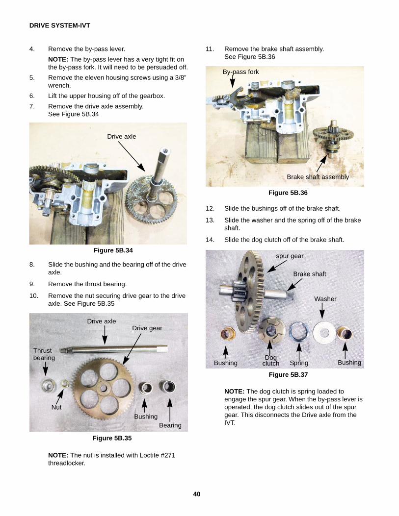
4. Remove the by-pass lever.NOTE: The by-pass lever has a very tight fit on the by-pass fork. It will need to be persuaded off.
5. Remove the eleven housing screws using a 3/8” wrench.
6. Lift the upper housing off of the gearbox.7. Remove the drive axle assembly.
See Figure 5B.34
8. Slide the bushing and the bearing off of the drive axle.
9. Remove the thrust bearing.
10. Remove the nut securing drive gear to the drive axle. See Figure 5B.35
NOTE: The nut is installed with Loctite #271 threadlocker.
11. Remove the brake shaft assembly. See Figure 5B.36
12. Slide the bushings off of the brake shaft.
13. Slide the washer and the spring off of the brake shaft.
14. Slide the dog clutch off of the brake shaft.
NOTE: The dog clutch is spring loaded to engage the spur gear. When the by-pass lever is operated, the dog clutch slides out of the spur gear. This disconnects the Drive axle from the IVT.
Figure 5B.34
Drive axle
Figure 5B.35
Drive axleDrive gear
Thrustbearing
BushingBearing
Nut
Figure 5B.36
Brake shaft assembly
By-pass fork
Figure 5B.37
BushingDog
clutch Spring
Washer
Bushing
spur gear
Brake shaft
DRIVE SYSTEM-IVT
41
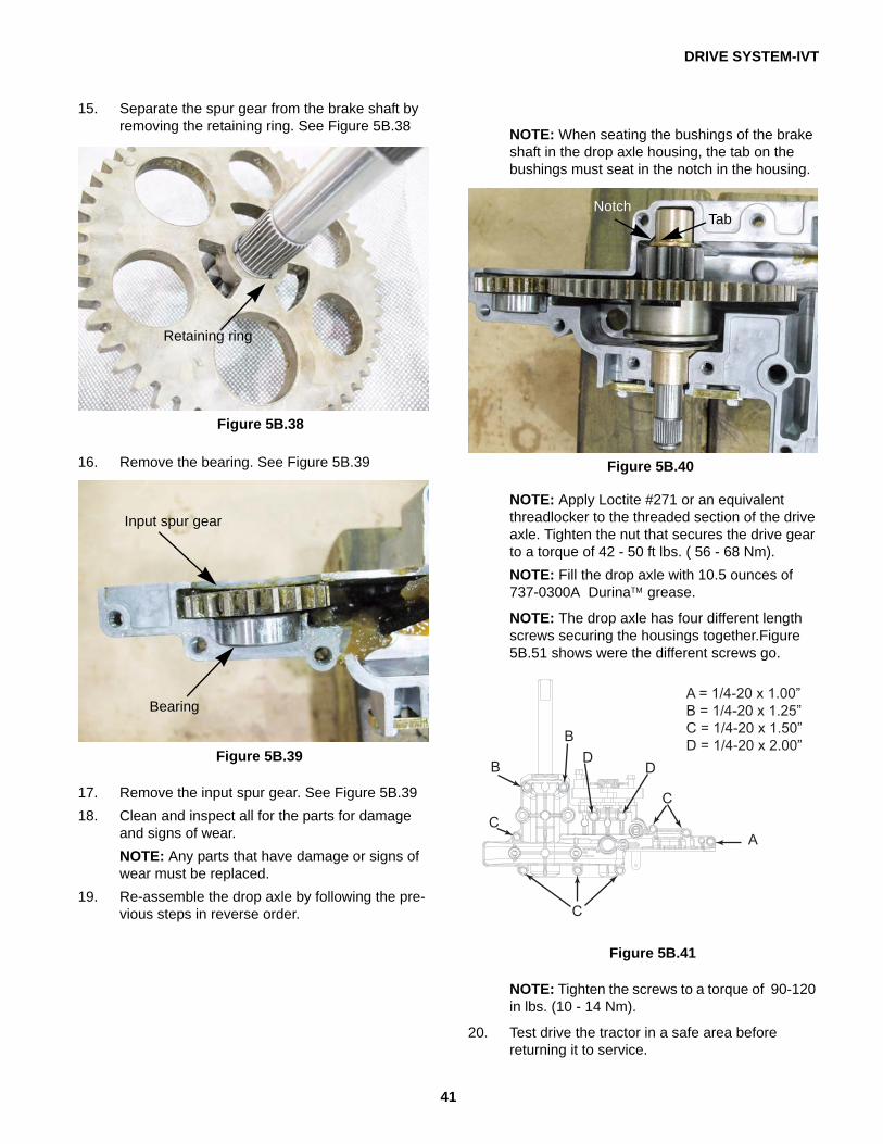
15. Separate the spur gear from the brake shaft by removing the retaining ring. See Figure 5B.38
16. Remove the bearing. See Figure 5B.39
17. Remove the input spur gear. See Figure 5B.3918. Clean and inspect all for the parts for damage
and signs of wear.NOTE: Any parts that have damage or signs of wear must be replaced.
19. Re-assemble the drop axle by following the pre-vious steps in reverse order.
Figure 5B.38
Retaining ring
Figure 5B.39
Input spur gear
Bearing
NOTE: When seating the bushings of the brake shaft in the drop axle housing, the tab on the bushings must seat in the notch in the housing.
NOTE: Apply Loctite #271 or an equivalent threadlocker to the threaded section of the drive axle. Tighten the nut that secures the drive gear to a torque of 42 - 50 ft lbs. ( 56 - 68 Nm).NOTE: Fill the drop axle with 10.5 ounces of 737-0300A DurinaTM grease.
NOTE: The drop axle has four different length screws securing the housings together.Figure 5B.51 shows were the different screws go.
NOTE: Tighten the screws to a torque of 90-120 in lbs. (10 - 14 Nm).
20. Test drive the tractor in a safe area before returning it to service.
Figure 5B.40
TabNotch
Figure 5B.41

DRIVE SYSTEM-IVT
42
Drive pedal shafts
The I-series tractors equipped with the IVT trans-mission have two drive pedal assemblies. The main drive pedal shaft is attached to the forward drive pedal. It operates the brakes and pulls the drive control links in the forward direction. The reverse drive pedal shaft is geared to the main drive shaft. When the reverse pedal is depressed, the reverse drive pedal shaft will rotate the main drive pedal shaft in the reverse direc-tion.
To remove the drive pedal shafts:
1. Remove the deck as described in chapter 8 Cut-ting Decks and Lift Shaft.
2. Remove the fender by following the steps described in Chapter 4: Body/Chassis.
3. Put a timing mark on the gears of the two shafts.
• One mark on the fourth tooth from the bottom of the reverse gear.
• One mark on the fourth valley from the valley of the main drive shaft gear. See Figure 5B.42
NOTE: The timing marks will make re-assembly easier.
4. Remove the reverse drive pedal:
NOTE: If the main drive pedal shaft is the only part that needs to be serviced, the reverse pedal shaft can be left in place. However Cub Cadet recommends removing the reverse pedal shaft and replacing the bushings at the same time.
NOTE: Worn bushings on either drive pedal shaft will cause some loss of wheel speed.
4a. Remove the hair pin clip and washer. See Figure 5B.43
4b. Remove the split hex bushing. See Figure 5B.44
Figure 5B.42
Timing marks
Figure 5B.43
Hair pin clipReverse pedal
shaft
Washer
Figure 5B.44
Split hex bushing
DRIVE SYSTEM-IVT
43
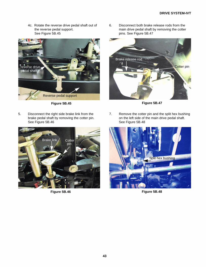
4c. Rotate the reverse drive pedal shaft out of the reverse pedal support. See Figure 5B.45
5. Disconnect the right side brake link from the brake pedal shaft by removing the cotter pin. See Figure 5B.46
Figure 5B.45
Reverse pedal support
reverse drive pedal shaft
Figure 5B.46
Brake link Cotterpin
6. Disconnect both brake release rods from the main drive pedal shaft by removing the cotter pins. See Figure 5B.47
7. Remove the cotter pin and the split hex bushing on the left side of the main drive pedal shaft. See Figure 5B.48
Figure 5B.47
Brake release rod
Cotter pin
Figure 5B.48
Split hex bushing

DRIVE SYSTEM-IVT
44
8. Remove the hair pin clip, washer and hex bush-ing from the right side of the main drive pedal shaft. See Figure 5B.49
9. Drive out both of the roll pins securing the drive pedal bracket to the main shaft using a 1/4” pin punch. See Figure 5B.50
10. Remove the three screws that secure the reverse pedal support using a 1/2” wrench. See Figure 5B.51
11. Lift up on the outer edge of the reverse pedal support while rotating it to the front to remove the support.
12. Slide the drive pedal bracket off of the main shaft.
13. Remove the rear screw on both sides of the drive pedal shaft support bracket. See Figure 5B.52
14. Remove the middle hex bushing. See Figure 5B.52
Figure 5B.49
Washer
Hair pin clipHex bushing
Figure 5B.50
Roll pins
Figure 5B.51
Remove these screws
Figure 5B.52
Remove this screw
Middle hexbushing

DRIVE SYSTEM-IVT
45
15. Swing the rear of the drive pedal shaft support bracket down.
16. Disconnect the steering gear box from the main shaft by removing the hair pin clip. See Figure 5B.53
17. Disconnect the reverse switch. See Figure 5B.54
18. Drop the left side of the main shaft out of slot.
19. Slide the main shaft out of the tractor.
Figure 5B.53
Hair pin clip
Steering gearboxarm
Figure 5B.54
Reverse switch.
To install the drive shaft assemblies:
1. Install the middle hex bushing. See Figure 5B.55
2. Slide the right side of the main shaft through the middle hex bushing. See Figure 5B.55
3. Connect the reverse switch.
4. Connect the steering gearbox:
4a. Slide the hole in the bell crank on the main shaft over the pin on the steering gearbox lever. See Figure 5B.56
4b. Install the hair pin clip. See Figure 5B.56
Figure 5B.55
Middle hex bushing
Figure 5B.56
Bell crank
Hair pin clip
Steering gearbox lever

DRIVE SYSTEM-IVT
46
5. Insert the main shaft into the hole for the left hex bushing by sliding it through the slot. See Figure 5B.57
NOTE: Do not install the hex bushing at this point. It will cause the main shaft to bind while working on the right side of the tractor.
6. Swing the rear of the drive pedal shaft support bracket into place.
7. Install the rear screw on each side of the drive pedal shaft support bracket. See Figure 5B.58
8. Slide the drive pedal bracket onto the main shaft.
NOTE: Do not install the roll pins at this point.
9. Install the reverse pedal support.
10. Install the hair pin clip, washer and hex bushing on the right side of the main drive pedal shaft. See Figure 5B.59
11. Secure the drive pedal bracket to the main shaft by driving the two roll pins.
12. Install the split hex bushing on the left side of the main shaft. See Figure 5B.60
13. Install a new cotter pin. See Figure 5B.60
14. Install both brake release rods from the main drive pedal shaft using new cotter pins. See Figure 5B.60
Figure 5B.57
Hole for hex bushing
Slot
Figure 5B.58
Rear screw
Drive pedal shaft support bracket
Figure 5B.59
Washer
Hair pin clipHex bushing
Figure 5B.60
Split hex bushing
Cotter pin
Left brake release rod
DRIVE SYSTEM-IVT
47
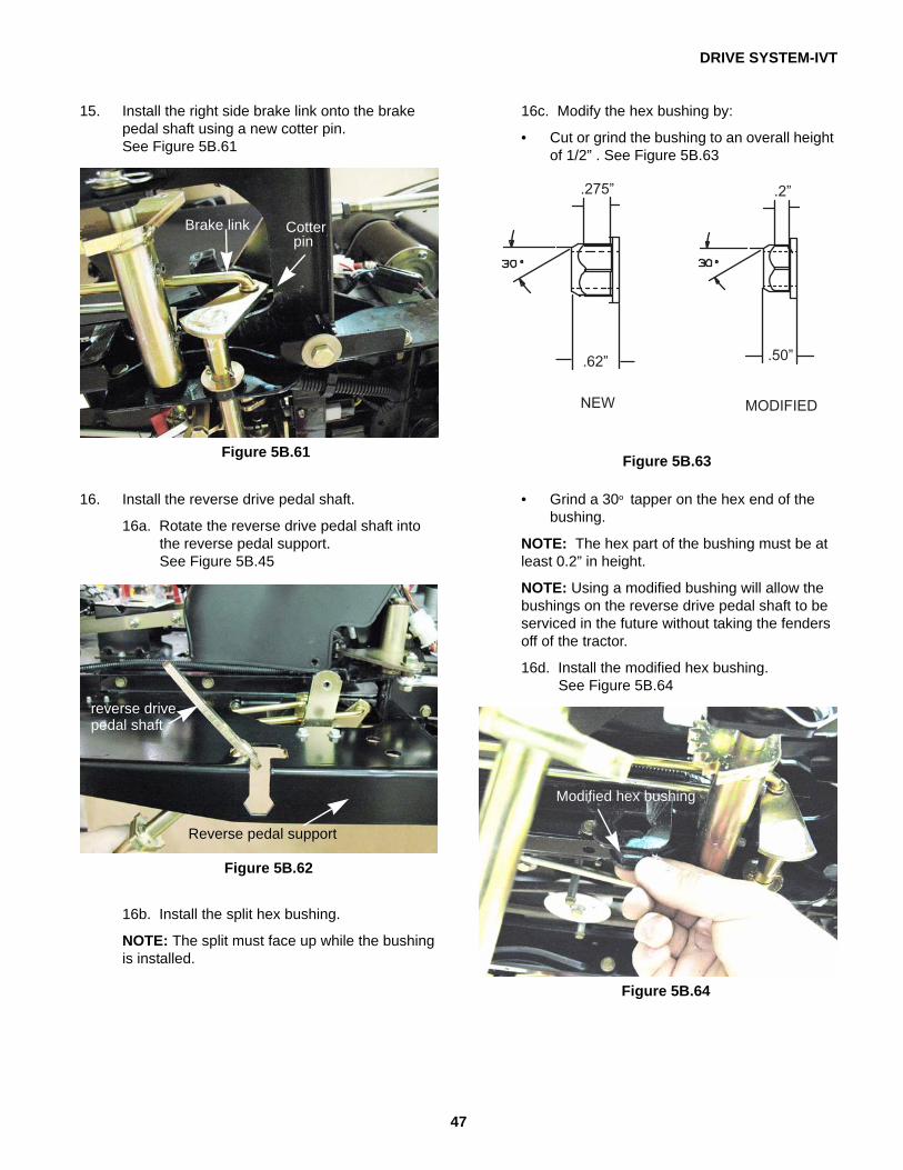
15. Install the right side brake link onto the brake pedal shaft using a new cotter pin. See Figure 5B.61
16. Install the reverse drive pedal shaft.
16a. Rotate the reverse drive pedal shaft into the reverse pedal support. See Figure 5B.45
16b. Install the split hex bushing.
NOTE: The split must face up while the bushing is installed.
Figure 5B.61
Brake link Cotterpin
Figure 5B.62
Reverse pedal support
reverse drive pedal shaft
16c. Modify the hex bushing by:
• Cut or grind the bushing to an overall height of 1/2” . See Figure 5B.63
• Grind a 30o tapper on the hex end of the bushing.
NOTE: The hex part of the bushing must be at least 0.2” in height.
NOTE: Using a modified bushing will allow the bushings on the reverse drive pedal shaft to be serviced in the future without taking the fenders off of the tractor.
16d. Install the modified hex bushing. See Figure 5B.64
Figure 5B.63
Figure 5B.64
Modified hex bushing
DRIVE SYSTEM-IVT
48
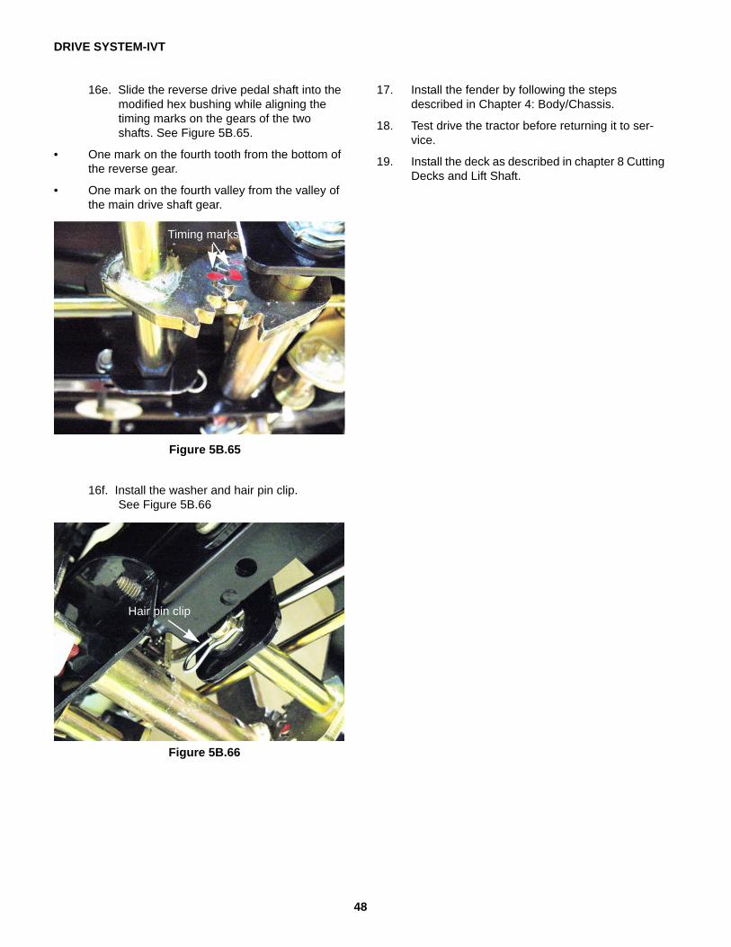
16e. Slide the reverse drive pedal shaft into the modified hex bushing while aligning the timing marks on the gears of the two shafts. See Figure 5B.65.
• One mark on the fourth tooth from the bottom of the reverse gear.
• One mark on the fourth valley from the valley of the main drive shaft gear.
16f. Install the washer and hair pin clip. See Figure 5B.66
17. Install the fender by following the steps described in Chapter 4: Body/Chassis.
18. Test drive the tractor before returning it to ser-vice.
19. Install the deck as described in chapter 8 Cutting Decks and Lift Shaft.
Figure 5B.65
Timing marks
Figure 5B.66
Hair pin clip