Embed Size (px)
Citation preview
Chapter 6
Advanced ModelingTools-I
After completing this chapter you will be able to:• Create holes using the Simple Hole option.• Create standard holes using Hole Wizard.• Apply simple and advanced fillets.• Understand various selection methods.• Chamfer the edges and vertices of the model.• Create the Shell feature.
Learning Objectives
c06-solidworks-2003.p65 5/12/2003, 4:59 PM1
6-2 SolidWorks for Designers
ADVANCED MODELING TOOLSThis chapter discusses various advanced modeling tools available in SolidWorks that assistyou in creating a better and accurate design by capturing the design intent in the model.For example, in the previous chapters you learned how to create a hole using the cut option.But in this chapter you will create holes using the Simple Hole option and Hole Wizardoption. Using the hole wizard, you can create the standard holes classified on the bases ofthe industrial standard, screw type, and size. Hole wizard of the SolidWorks is one of thelargest standard industrial virtual hole generation machine available in any CAD package.You will also learn about some other advanced modeling tools such as fillet, chamfer, andshell in this chapter.
Creating Simple Hole
The Simple Hole option is used to apply simple hole feature. In previous chapteryou learned to create holes by sketching a circle and then using the cut option tocomplete hole creation. But using the simple hole option you do not need to create
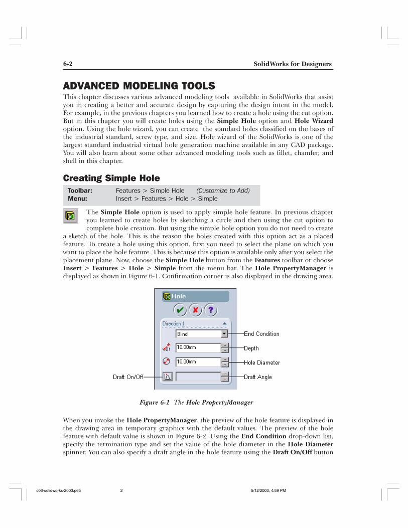
a sketch of the hole. This is the reason the holes created with this option act as a placedfeature. To create a hole using this option, first you need to select the plane on which youwant to place the hole feature. This is because this option is available only after you select theplacement plane. Now, choose the Simple Hole button from the Features toolbar or chooseInsert > Features > Hole > Simple from the menu bar. The Hole PropertyManager isdisplayed as shown in Figure 6-1. Confirmation corner is also displayed in the drawing area.
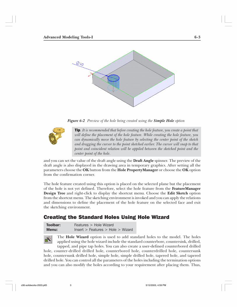
When you invoke the Hole PropertyManager, the preview of the hole feature is displayed inthe drawing area in temporary graphics with the default values. The preview of the holefeature with default value is shown in Figure 6-2. Using the End Condition drop-down list,specify the termination type and set the value of the hole diameter in the Hole Diameterspinner. You can also specify a draft angle in the hole feature using the Draft On/Off button
Toolbar: Features > Simple Hole (Customize to Add)
Menu: Insert > Features > Hole > Simple
Figure 6-1 The Hole PropertyManager
c06-solidworks-2003.p65 5/12/2003, 4:59 PM2
Advanced Modeling Tools-I 6-3
Figure 6-2 Preview of the hole being created using the Simple Hole option
and you can set the value of the draft angle using the Draft Angle spinner. The preview of thedraft angle is also displayed in the drawing area in temporary graphics. After setting all theparameters choose the OK button from the Hole PropertyManager or choose the OK optionfrom the confirmation corner.
The hole feature created using this option is placed on the selected plane but the placementof the hole is not yet defined. Therefore, select the hole feature from the FeatureManagerDesign Tree and right-click to display the shortcut menu. Choose the Edit Sketch optionfrom the shortcut menu. The sketching environment is invoked and you can apply the relationsand dimensions to define the placement of the hole feature on the selected face and exitthe sketching environment.
Creating the Standard Holes Using Hole Wizard
The Hole Wizard option is used to add standard holes to the model. The holesapplied using the hole wizard include the standard counterbore, countersink, drilled,tapped, and pipe tap holes. You can also create a user-defined counterbored drilled
hole, counter-drilled drilled hole, counterbored hole, counterdrilled hole, countersunkhole, countersunk drilled hole, simple hole, simple drilled hole, tapered hole, and tapereddrilled hole. You can control all the parameters of the holes including the termination optionsand you can also modify the holes according to your requirement after placing them. Thus,
Tip. It is recommended that before creating the hole feature, you create a point thatwill define the placement of the hole feature. While creating the hole feature, youcan dynamically move the hole feature by selecting the center point of the sketchand dragging the cursor to the point sketched earlier. The cursor will snap to thatpoint and coincident relation will be appiled between the sketched point and thecenter point of the hole.
Toolbar: Features > Hole WizardMenu: Insert > Features > Hole > Wizard
c06-solidworks-2003.p65 5/12/2003, 4:59 PM3
6-4 SolidWorks for Designers
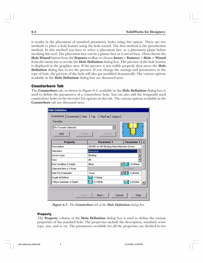
Figure 6-3 The Counterbore tab of the Hole Definition dialog box
it results in the placement of standard parametric holes using this option. There are twomethods to place a hole feature using the hole wizard. The first method is the preselectionmethod. In this method you have to select a placement face or a placement plane beforeinvoking this tool. The placement face can be a planar face or a curved face. Then choose theHole Wizard button from the Features toolbar or choose Insert > Features > Hole > Wizardfrom the menu bar to invoke the Hole Definition dialog box. The preview of the hole featureis displayed in the graphics area. If the preview is not visible properly then move the HoleDefinition dialog box to see the preview. If you change the settings and parameters or thetype of hole, the preview of the hole will also get modified dynamically. The various optionsavailable in the Hole Definition dialog box are discussed next.
Counterbore TabThe Counterbore tab, as shown in Figure 6-3, available in the Hole Definition dialog box isused to define the parameters of a counterbore hole. You can also add the frequently usedcounterbore holes in the favorites list options in this tab. The various options available in theCounterbore tab are discussed next.
PropertyThe Property column of the Hole Definition dialog box is used to define the variousproperties of the standard hole. The properties include the description, standard, screwtype, size, and so on. The parameters available for all the properties are divided in two
c06-solidworks-2003.p65 5/12/2003, 4:59 PM4
Advanced Modeling Tools-I 6-5
columns. The name of the columns are Parameter 1 and Parameter 2. These two columnsare used to define the values and other related information to create the hole. The variousoptions available in the Property column are discussed next.
DescriptionThe Description option is used to display the name and the description of the standardhole.
StandardThe Standard option is used to specify the industrial dimensioning and hole standard.You can select the standard from the Standard drop-down list available in theParameter 1 column. By default, the Ansi Inch standard is selected. Various otherdimensioning standards are available in this drop-down list such as Ansi Metric,BSI, DIN, ISO, JIS, DME Mould Bases, Hasco Metric Mould Bases, PCS MouldBases, Progressive Mould Bases, and Superior Mould Bases.
Screw typeThe Screw type option is used to define the type of fastener to be inserted in thehole. The standard holes created using the Hole Wizard depend on the fastener tobe inserted in that hole and the size of the fastener. Therefore, creation of a holebased on the fastener to be used in that hole is a good practice and is the uniquefeature of SolidWorks. You can select the screw type from the Screw Type drop-downlist available in the Parameter 1 column. The types of screws available in the drop-downlist depend on the standard selected from the Standard drop-down list.
SizeThe Size option is used to define the size of the fastener that will be inserted in thehole that is created using the Hole Wizard. The size of the fastener is selected fromthe Size drop-down list available in the Parameter 1 column. The sizes of the fastenersavailable in the Size drop-down list depend on the standard selected from theStandard drop-down list.
End Condition and DepthThe End Condition and Depth option is used to define the end condition of featuretermination. To define the end condition for feature termination, select the endcondition option from the End Condition drop-down list available in the Parameter 1area. By default, the Blind option is selected in this drop-down list. Therefore, if theend condition is Blind you have to specify the depth of feature termination. This isthe reason the Depth area available on the right of the End Condition drop-downlist in the Parameter 2 column is replaced by the edit box when clicked once. You canspecify the depth of feature termination in this edit box.
NoteA preview area is provided on the top right of the Hole Definition area. You can observe thepreview of the hole being created. The preview of the hole feature is changed dynamically as youchange the parameters of the hole feature.
c06-solidworks-2003.p65 5/12/2003, 4:59 PM5
6-6 SolidWorks for Designers
Selected Item and OffsetThe Selected Item and Offset option is used to define the surface for featuretermination. The Selected Item display area in the Parameter 1 column is activeonly when the Up To Vertex, Up To Surface, or Offset From Surface option isselected from the End Condition drop-down list. The Offset area available on theright of the Select Item display area is replaced by the Offset edit box and you canenter the value of offset in this edit box. This option is available only when you selectthe Offset From Surface option from the End Condition drop-down list.
Hole Fit and DiameterThe Hole Fit and Diameter option is used to specify the type of Fit to be applied inthe hole to be created. The types of fits are available in the Hole Fit drop-down list inthe Parameter 1 column. The types of fits available in the Hole Fit drop-down listare Close, Normal, and Loose. The Diameter area on the right of the Hole Fitdrop-down list in the Parameter 2 area is replaced by the Diameter edit box byclicking once in this area. The value of the diameter in this area is the default valueaccording to the standard. The value changes depending upon the type of hole fitselected from the Hole Fit drop-down list. You can also modify this value accordingto the requirement.
Angle at BottomThe Angle at Bottom option is used to specify the angle at the bottom of the holefeature. The Angle at Bottom area available in the Parameter 1 column is replacedby the Angle at Bottom edit box by clicking once. You can modify the default valuefor the angle at bottom by entering a new value in this edit box.
C’Bore Diameter and DepthThe C’Bore Diameter and Depth option is used to specify the diameter of thecounterbore and the depth of the counterbore. The C’Bore Diameter area is availablein the Parameter 1 column and is replaced by the C’Bore Diameter edit box byclicking once to modify the default value. The Depth area available on the right ofthe C’Bore Diameter area is replaced by the Depth edit box by clicking once and youcan modify the default depth of the counterbore.
Head ClearanceThe Head Clearance option available in the Property column is used to specify theclearance distance between the head of the fastener and the placement plane of thehole feature. The Head Clearance area available in the Parameter 1 column isreplaced by the Head Clearance edit box by clicking once and you can modify thedefault head clearance value.
Near Side C’Sink Dia. and AngleThe Near Side C’Sink Dia. and Angle option is used to specify the diameter and theangle for the countersink on the upper face, which is the placement plane of thehole feature. The diameter is specified in the Near Side C’Sink Dia. area of theParameter 1 column and the angle is specified in the Angle area of the Parameter 2column.
c06-solidworks-2003.p65 5/12/2003, 4:59 PM6
Advanced Modeling Tools-I 6-7
Under Hd C’Sink Dia. and AngleThe Under Hd C’Sink Dia. and Angle option is used to specify the diameter and theangle for the countersink to be applied at the end of the counterbore head. Thediameter is specified in the Under Hd C’Sink Dia. area in the Parameter 1 columnand the angle is specified in the Angle area in the Parameter 2 column.
Far Side C’SinkDia. and AngleThe Far Side C’Sink Dia. and Angle option is used to specify the diameter and theangle for the countersink to be applied at the end of the hole feature. This option isavailable only if the Through All or the Up To Next option is selected from the EndCondition drop-down list. The diameter is specified in the Far Side C’Sink Dia. areain the Parameter 1 column and the angle is specified in the Angle area in theParameter 2 column.
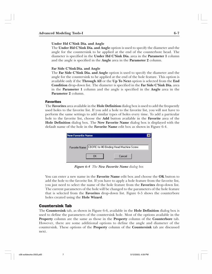
FavoritesThe Favorites area available in the Hole Definition dialog box is used to add the frequentlyused holes to the favorite list. If you add a hole to the favorite list, you will not have toperform the same settings to add similar types of holes every time. To add a particularhole to the favorite list, choose the Add button available in the Favorite area of theHole Definition dialog box. The New Favorite Name dialog box is displayed with thedefault name of the hole in the Favorite Name edit box as shown in Figure 6-4.
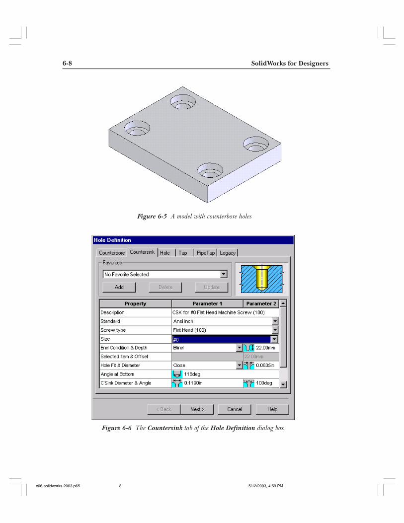
You can enter a new name in the Favorite Name edit box and choose the OK button toadd the hole to the favorite list. If you have to apply a hole feature from the favorite list,you just need to select the name of the hole feature from the Favorites drop-down list.The current parameters of the hole will be changed to the parameters of the hole featurethat is selected from the Favorites drop-down list. Figure 6-5 shows the counterboreholes created using the Hole Wizard.
Countersink TabThe Countersink tab, as shown in Figure 6-6, available in the Hole Definition dialog box isused to define the parameters of the countersink hole. Most of the options available in theProperty column are the same as those in the Property column of the Counterbore tab.However, there are some additional options to define the angle and diameter of thecountersink. These options of the Property column of the Countersink tab are discussednext.
Figure 6-4 The New Favorite Name dialog box
c06-solidworks-2003.p65 5/12/2003, 4:59 PM7
6-8 SolidWorks for Designers
Figure 6-5 A model with counterbore holes
Figure 6-6 The Countersink tab of the Hole Definition dialog box
c06-solidworks-2003.p65 5/12/2003, 4:59 PM8
Advanced Modeling Tools-I 6-9
PropertyThe Property column of the Hole Definition dialog box is used to define the parametersof the countersink hole. As mentioned earlier, most of the options are the same as discussedin the Property column of the Counterbore tab. The options that have been discussedearlier are not included here. Some options that are not used to create only a counterboreand are not used in countersink are not available in this tab. Only the additional optionsavailable in the Property column of the Countersink tab are discussed next.
C’Sink Diameter and AngleThe C’Sink Diameter and Angle option is used to define the diameter and the angleof the countersink. The C’Sink Diameter area in the Parameter 1 column is changedto the C’Sink Diameter edit box when clicked once. The value of the countersinkdiameter is specified in this edit box. The Angle area available in the Parameter 2area is replaced by the Angle edit box when clicked once. The value of the angle ofcountersink is specified in this edit box.
Head Clearance and TypeThe Head Clearance and Type option is used to define the head clearance distancebetween the placement surface of the hole feature and the top face of the fastenerand to define the type of the counter to be added. The Head Clearance area availablein the Parameter 1 column is replaced by the Head Clearance edit box when clickedonce. The value of the clearance distance is specified in this edit box. The Typedrop-down list available on the right of the Head Clearance area is used to specify ifthe clearance distance is compensated by extending the countersink or by adding acounterbore.
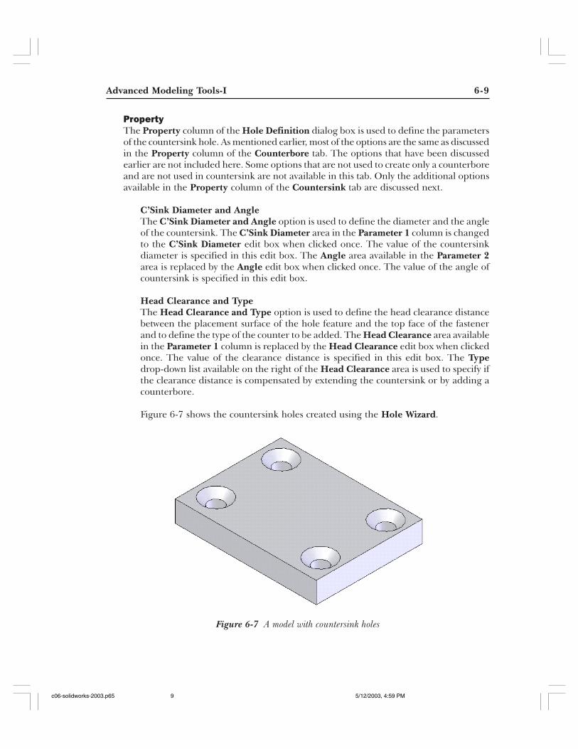
Figure 6-7 shows the countersink holes created using the Hole Wizard.
Figure 6-7 A model with countersink holes
c06-solidworks-2003.p65 5/12/2003, 4:59 PM9
6-10 SolidWorks for Designers
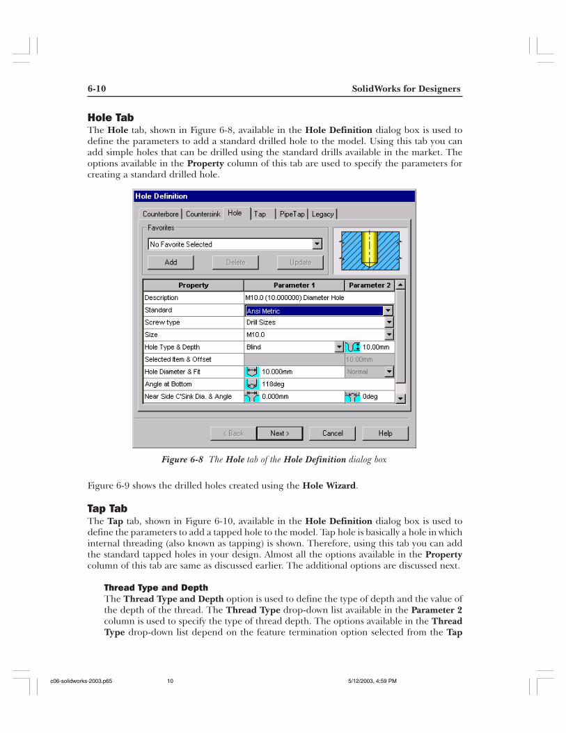
Hole TabThe Hole tab, shown in Figure 6-8, available in the Hole Definition dialog box is used todefine the parameters to add a standard drilled hole to the model. Using this tab you canadd simple holes that can be drilled using the standard drills available in the market. Theoptions available in the Property column of this tab are used to specify the parameters forcreating a standard drilled hole.
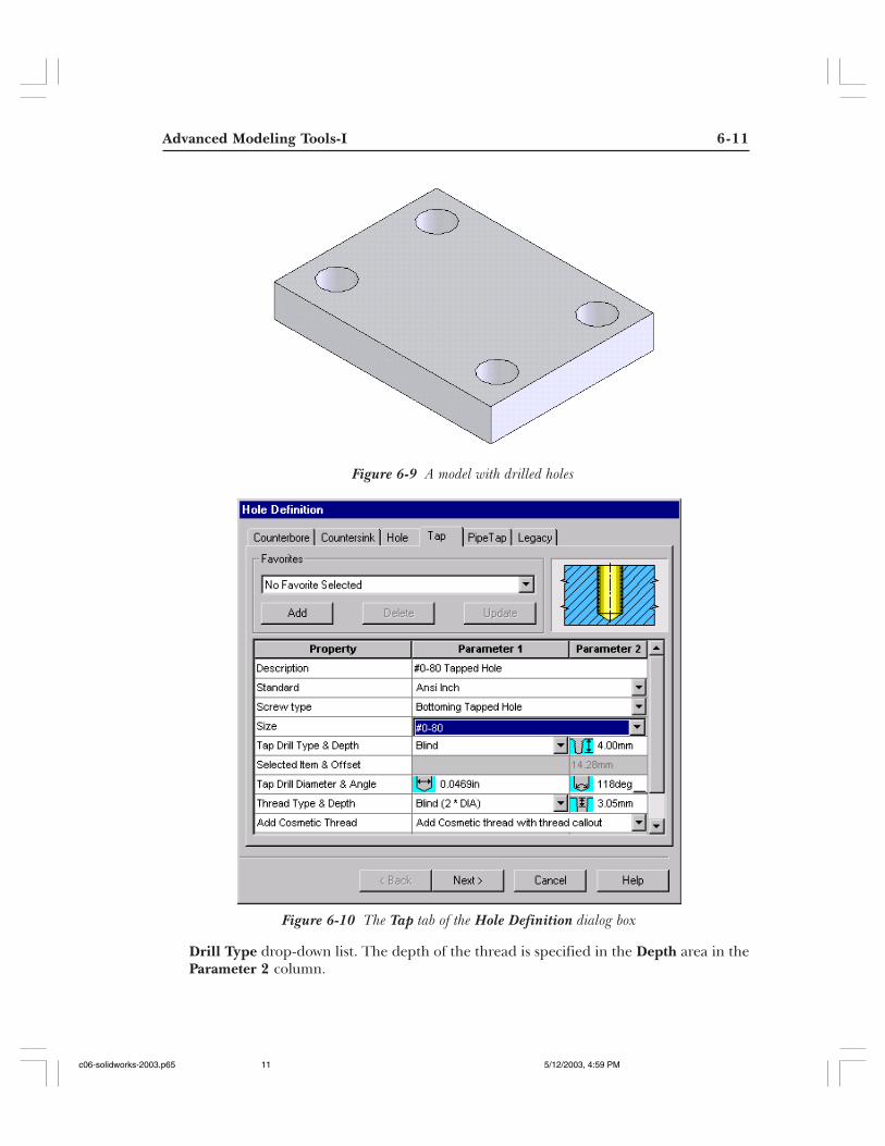
Figure 6-9 shows the drilled holes created using the Hole Wizard.
Tap TabThe Tap tab, shown in Figure 6-10, available in the Hole Definition dialog box is used todefine the parameters to add a tapped hole to the model. Tap hole is basically a hole in whichinternal threading (also known as tapping) is shown. Therefore, using this tab you can addthe standard tapped holes in your design. Almost all the options available in the Propertycolumn of this tab are same as discussed earlier. The additional options are discussed next.
Thread Type and DepthThe Thread Type and Depth option is used to define the type of depth and the value ofthe depth of the thread. The Thread Type drop-down list available in the Parameter 2column is used to specify the type of thread depth. The options available in the ThreadType drop-down list depend on the feature termination option selected from the Tap
Figure 6-8 The Hole tab of the Hole Definition dialog box
c06-solidworks-2003.p65 5/12/2003, 4:59 PM10
Advanced Modeling Tools-I 6-11
Drill Type drop-down list. The depth of the thread is specified in the Depth area in theParameter 2 column.
Figure 6-9 A model with drilled holes
Figure 6-10 The Tap tab of the Hole Definition dialog box
c06-solidworks-2003.p65 5/12/2003, 4:59 PM11
6-12 SolidWorks for Designers
Tip. In the modern modeling practice, the creation of threads is avoided in modelsbecause it results in the creation of complex geometry. When you generate the viewsfrom that model, the views generated contain the complex geometry, which is difficultto understand. Therefore, it is a better practice to avoid the creation of threads inthe model and add the cosmetic threads. Using the cosmetic threads you will get thethread convention in the drawing views, which is recommended, instead of creatingcomplete thread.
Add Cosmetic ThreadThe Add Cosmetic Thread option is used to add the cosmetic threads while creating atapped hole. The Add Cosmetic Thread drop-down list is available in the Parameter 1column. If you select the No Cosmetic thread option from this drop-down list, the cosmeticthread will not be added to the tapped hole. If you select the Add Cosmetic thread withthread callout option from this drop-down list, the cosmetic thread and the thread calloutwill be added to the tapped hole feature. The Add Cosmetic Thread without threadcallout option is used to add only the cosmetic thread to the hole feature.
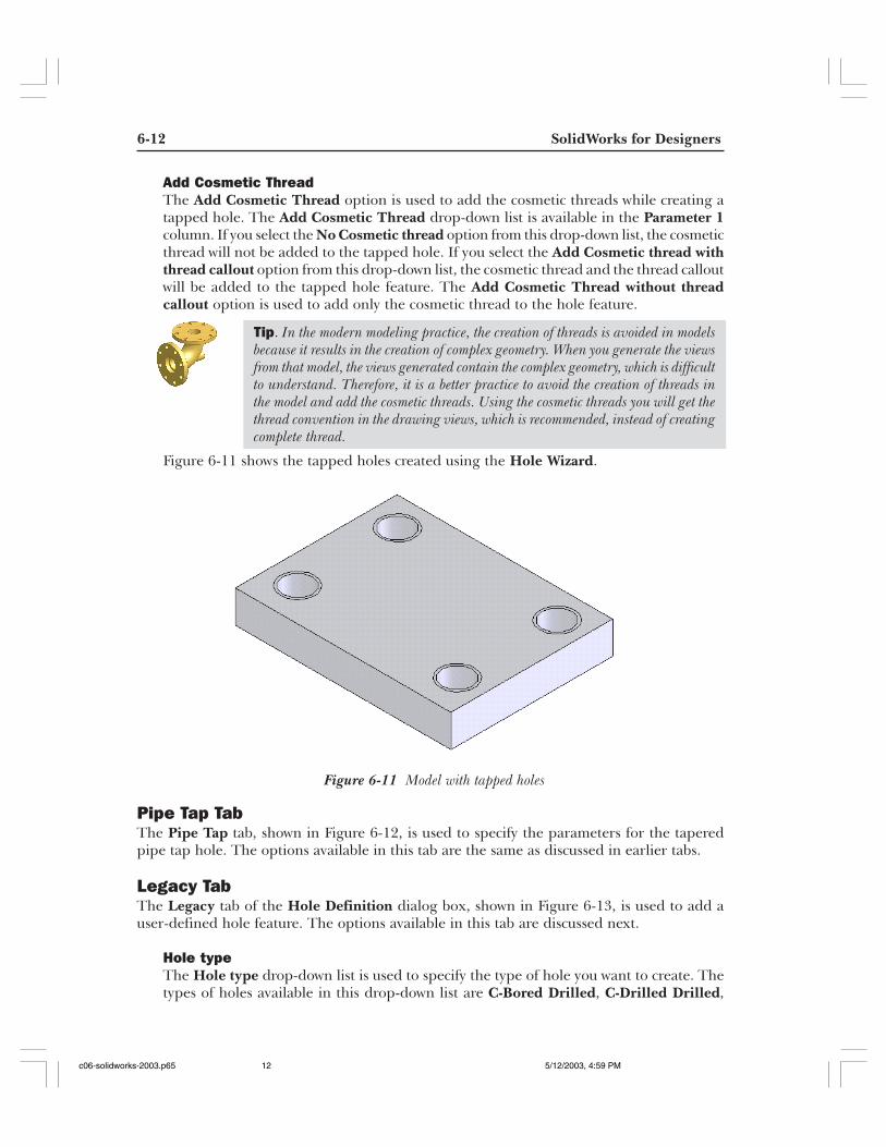
Figure 6-11 shows the tapped holes created using the Hole Wizard.
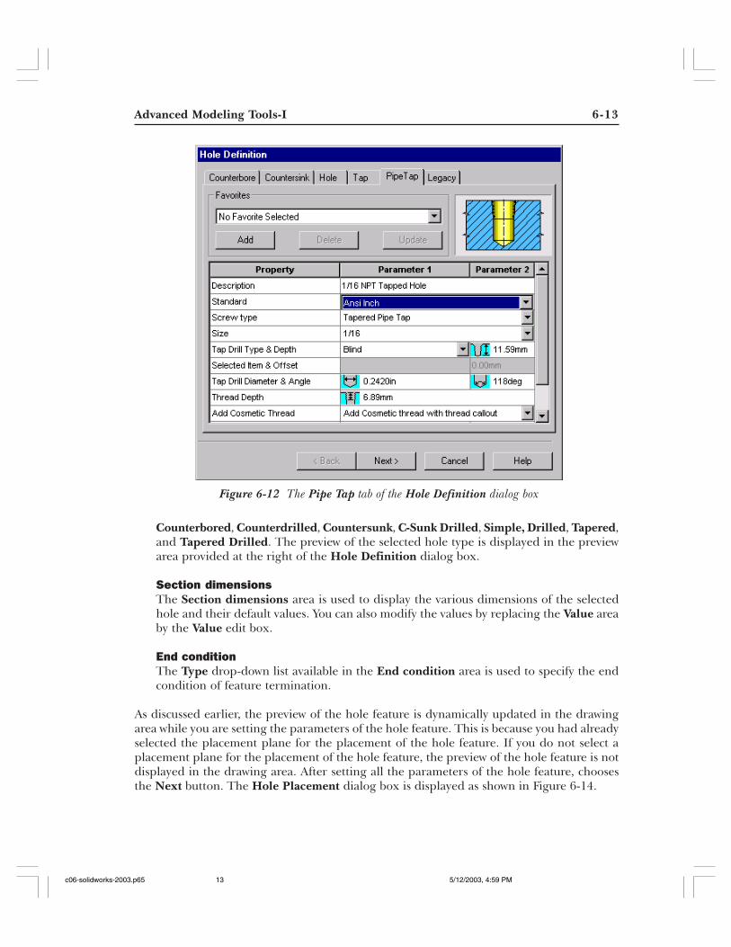
Pipe Tap TabThe Pipe Tap tab, shown in Figure 6-12, is used to specify the parameters for the taperedpipe tap hole. The options available in this tab are the same as discussed in earlier tabs.
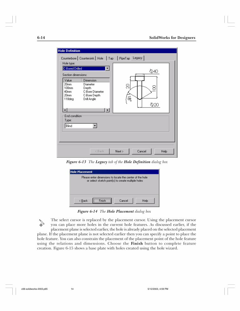
Legacy TabThe Legacy tab of the Hole Definition dialog box, shown in Figure 6-13, is used to add auser-defined hole feature. The options available in this tab are discussed next.
Hole typeThe Hole type drop-down list is used to specify the type of hole you want to create. Thetypes of holes available in this drop-down list are C-Bored Drilled, C-Drilled Drilled,
Figure 6-11 Model with tapped holes
c06-solidworks-2003.p65 5/12/2003, 4:59 PM12
Advanced Modeling Tools-I 6-13
Counterbored, Counterdrilled, Countersunk, C-Sunk Drilled, Simple, Drilled, Tapered,and Tapered Drilled. The preview of the selected hole type is displayed in the previewarea provided at the right of the Hole Definition dialog box.
Section dimensionsThe Section dimensions area is used to display the various dimensions of the selectedhole and their default values. You can also modify the values by replacing the Value areaby the Value edit box.
End conditionThe Type drop-down list available in the End condition area is used to specify the endcondition of feature termination.
As discussed earlier, the preview of the hole feature is dynamically updated in the drawingarea while you are setting the parameters of the hole feature. This is because you had alreadyselected the placement plane for the placement of the hole feature. If you do not select aplacement plane for the placement of the hole feature, the preview of the hole feature is notdisplayed in the drawing area. After setting all the parameters of the hole feature, choosesthe Next button. The Hole Placement dialog box is displayed as shown in Figure 6-14.
Figure 6-12 The Pipe Tap tab of the Hole Definition dialog box
c06-solidworks-2003.p65 5/12/2003, 4:59 PM13
6-14 SolidWorks for Designers
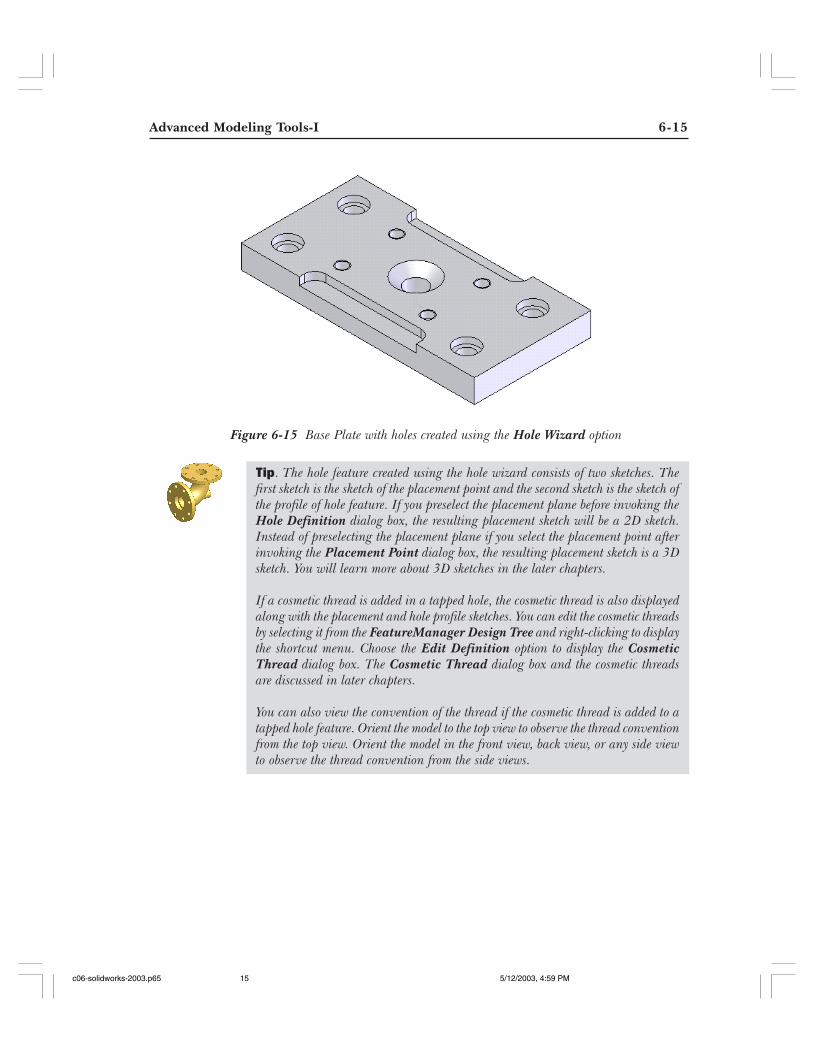
Figure 6-14 The Hole Placement dialog box
The select cursor is replaced by the placement cursor. Using the placement cursoryou can place more holes in the current hole features. As discussed earlier, if theplacement plane is selected earlier, the hole is already placed on the selected placement
plane. If the placement plane is not selected earlier then you can specify a point to place thehole feature. You can also constrain the placement of the placement point of the hole featureusing the relations and dimensions. Choose the Finish button to complete featurecreation. Figure 6-15 shows a base plate with holes created using the hole wizard.
Figure 6-13 The Legacy tab of the Hole Definition dialog box
c06-solidworks-2003.p65 5/12/2003, 4:59 PM14
Advanced Modeling Tools-I 6-15
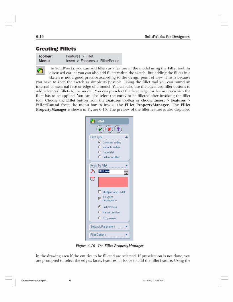
Figure 6-15 Base Plate with holes created using the Hole Wizard option
Tip. The hole feature created using the hole wizard consists of two sketches. Thefirst sketch is the sketch of the placement point and the second sketch is the sketch ofthe profile of hole feature. If you preselect the placement plane before invoking theHole Definition dialog box, the resulting placement sketch will be a 2D sketch.Instead of preselecting the placement plane if you select the placement point afterinvoking the Placement Point dialog box, the resulting placement sketch is a 3Dsketch. You will learn more about 3D sketches in the later chapters.
If a cosmetic thread is added in a tapped hole, the cosmetic thread is also displayedalong with the placement and hole profile sketches. You can edit the cosmetic threadsby selecting it from the FeatureManager Design Tree and right-clicking to displaythe shortcut menu. Choose the Edit Definition option to display the CosmeticThread dialog box. The Cosmetic Thread dialog box and the cosmetic threadsare discussed in later chapters.
You can also view the convention of the thread if the cosmetic thread is added to atapped hole feature. Orient the model to the top view to observe the thread conventionfrom the top view. Orient the model in the front view, back view, or any side viewto observe the thread convention from the side views.
c06-solidworks-2003.p65 5/12/2003, 4:59 PM15
6-16 SolidWorks for Designers
Figure 6-16 The Fillet PropertyManager
Creating Fillets
In SolidWorks, you can add fillets as a feature in the model using the Fillet tool. Asdiscussed earlier you can also add fillets within the sketch. But adding the fillets in asketch is not a good practice according to the design point of view. This is because
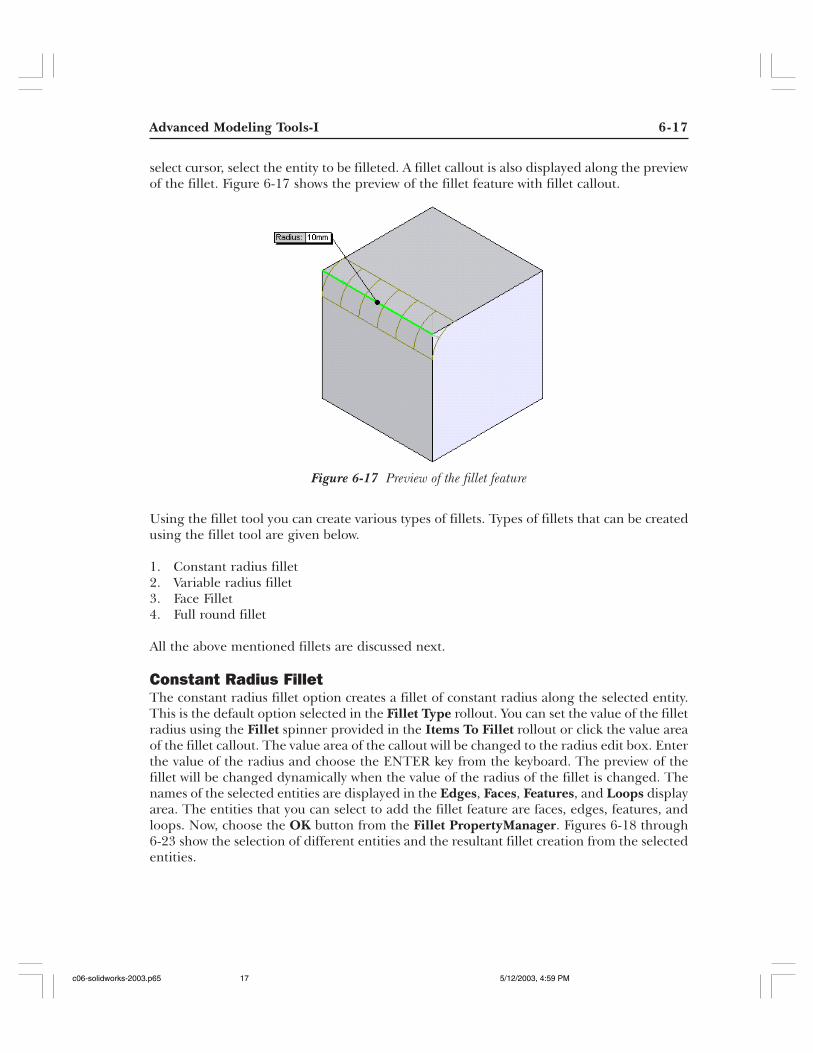
you have to keep the sketch as simple as possible. Using the fillet tool you can round aninternal or external face or edge of a model. You can also use the advanced fillet options toadd advanced fillets to the model. You can preselect the face, edge, or feature on which thefillet has to be applied. You can also select the entity to be filleted after invoking the fillettool. Choose the Fillet button from the Features toolbar or choose Insert > Features >Fillet/Round from the menu bar to invoke the Fillet PropertyManager. The FilletPropertyManager is shown in Figure 6-16. The preview of the fillet feature is also displayed
in the drawing area if the entities to be filleted are selected. If preselection is not done, youare prompted to select the edges, faces, features, or loops to add the fillet feature. Using the
Toolbar: Features > FilletMenu: Insert > Features > Fillet/Round
c06-solidworks-2003.p65 5/12/2003, 4:59 PM16
Advanced Modeling Tools-I 6-17
Figure 6-17 Preview of the fillet feature
select cursor, select the entity to be filleted. A fillet callout is also displayed along the previewof the fillet. Figure 6-17 shows the preview of the fillet feature with fillet callout.
Using the fillet tool you can create various types of fillets. Types of fillets that can be createdusing the fillet tool are given below.
1. Constant radius fillet2. Variable radius fillet3. Face Fillet4. Full round fillet
All the above mentioned fillets are discussed next.
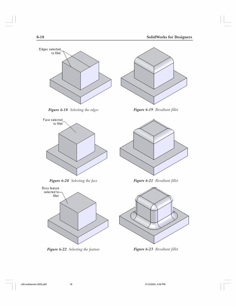
Constant Radius FilletThe constant radius fillet option creates a fillet of constant radius along the selected entity.This is the default option selected in the Fillet Type rollout. You can set the value of the filletradius using the Fillet spinner provided in the Items To Fillet rollout or click the value areaof the fillet callout. The value area of the callout will be changed to the radius edit box. Enterthe value of the radius and choose the ENTER key from the keyboard. The preview of thefillet will be changed dynamically when the value of the radius of the fillet is changed. Thenames of the selected entities are displayed in the Edges, Faces, Features, and Loops displayarea. The entities that you can select to add the fillet feature are faces, edges, features, andloops. Now, choose the OK button from the Fillet PropertyManager. Figures 6-18 through6-23 show the selection of different entities and the resultant fillet creation from the selectedentities.
c06-solidworks-2003.p65 5/12/2003, 4:59 PM17
6-18 SolidWorks for Designers
Figure 6-22 Selecting the feature Figure 6-23 Resultant fillet
Figure 6-20 Selecting the face Figure 6-21 Resultant fillet
Figure 6-18 Selecting the edges Figure 6-19 Resultant fillet
c06-solidworks-2003.p65 5/12/2003, 4:59 PM18
Advanced Modeling Tools-I 6-19
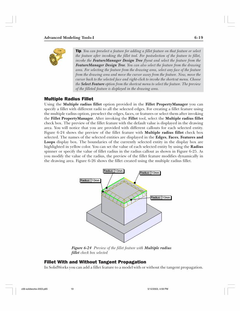
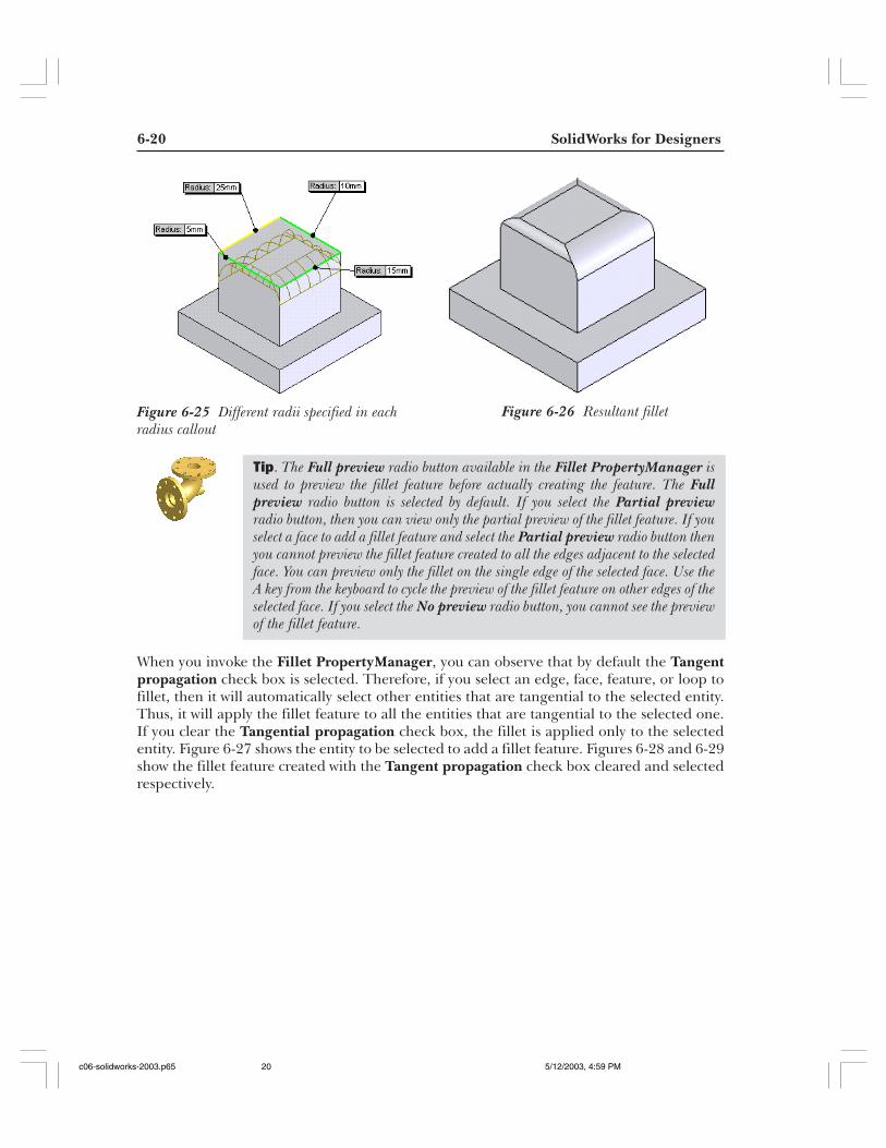
Multiple Radius FilletUsing the Multiple radius fillet option provided in the Fillet PropertyManager you canspecify a fillet with different radii to all the selected edges. For creating a fillet feature usingthe multiple radius option, preselect the edges, faces, or features or select them after invokingthe Fillet PropertyManager. After invoking the Fillet tool, select the Multiple radius filletcheck box. The preview of the fillet feature with the default value is displayed in the drawingarea. You will notice that you are provided with different callouts for each selected entity.Figure 6-24 shows the preview of the fillet feature with Multiple radius fillet check boxselected. The names of the selected entities are displayed in the Edges, Faces, Features andLoops display box. The boundaries of the currently selected entity in the display box arehighlighted in yellow color. You can set the value of each selected entity by using the Radiusspinner or specify the value of fillet radius in the radius callout as shown in Figure 6-25. Asyou modify the value of the radius, the preview of the fillet feature modifies dynamically inthe drawing area. Figure 6-26 shows the fillet created using the multiple radius fillet.
Fillet With and Without Tangent PropagationIn SolidWorks you can add a fillet feature to a model with or without the tangent propagation.
Tip. You can preselect a feature for adding a fillet feature on that feature or selectthe feature after invoking the fillet tool. For postselection of the feature to fillet,invoke the FeatureManager Design Tree flyout and select the feature from theFeatureManager Design Tree. You can also select the feature from the drawingarea. For selecting the feature from the drawing area, select any face of the featurefrom the drawing area and move the cursor away from the feature. Now, move thecursor back to the selected face and right-click to invoke the shortcut menu. Choosethe Select Feature option from the shortcut menu to select the feature. The previewof the filleted feature is displayed in the drawing area.
Figure 6-24 Preview of the fillet feature with Multiple radiusfillet check box selected
c06-solidworks-2003.p65 5/12/2003, 4:59 PM19
6-20 SolidWorks for Designers
Figure 6-25 Different radii specified in eachradius callout
Figure 6-26 Resultant fillet
Tip. The Full preview radio button available in the Fillet PropertyManager isused to preview the fillet feature before actually creating the feature. The Fullpreview radio button is selected by default. If you select the Partial previewradio button, then you can view only the partial preview of the fillet feature. If youselect a face to add a fillet feature and select the Partial preview radio button thenyou cannot preview the fillet feature created to all the edges adjacent to the selectedface. You can preview only the fillet on the single edge of the selected face. Use theA key from the keyboard to cycle the preview of the fillet feature on other edges of theselected face. If you select the No preview radio button, you cannot see the previewof the fillet feature.
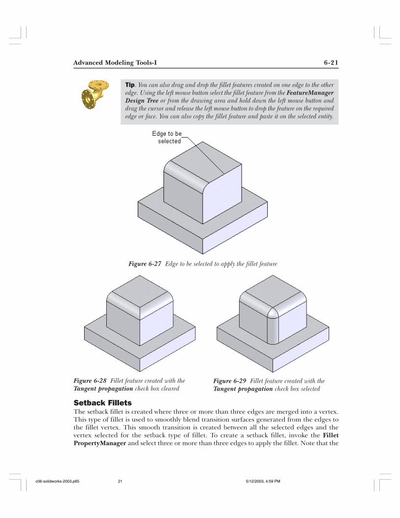
When you invoke the Fillet PropertyManager, you can observe that by default the Tangentpropagation check box is selected. Therefore, if you select an edge, face, feature, or loop tofillet, then it will automatically select other entities that are tangential to the selected entity.Thus, it will apply the fillet feature to all the entities that are tangential to the selected one.If you clear the Tangential propagation check box, the fillet is applied only to the selectedentity. Figure 6-27 shows the entity to be selected to add a fillet feature. Figures 6-28 and 6-29show the fillet feature created with the Tangent propagation check box cleared and selectedrespectively.
c06-solidworks-2003.p65 5/12/2003, 4:59 PM20
Advanced Modeling Tools-I 6-21
Setback FilletsThe setback fillet is created where three or more than three edges are merged into a vertex.This type of fillet is used to smoothly blend transition surfaces generated from the edges tothe fillet vertex. This smooth transition is created between all the selected edges and thevertex selected for the setback type of fillet. To create a setback fillet, invoke the FilletPropertyManager and select three or more than three edges to apply the fillet. Note that the
Figure 6-27 Edge to be selected to apply the fillet feature
Figure 6-28 Fillet feature created with theTangent propagation check box cleared
Figure 6-29 Fillet feature created with theTangent propagation check box selected
Tip. You can also drag and drop the fillet features created on one edge to the otheredge. Using the left mouse button select the fillet feature from the FeatureManagerDesign Tree or from the drawing area and hold down the left mouse button anddrag the cursor and release the left mouse button to drop the feature on the requirededge or face. You can also copy the fillet feature and paste it on the selected entity.
c06-solidworks-2003.p65 5/12/2003, 4:59 PM21
6-22 SolidWorks for Designers
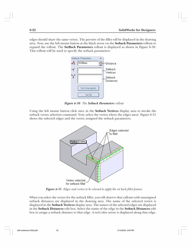
edges should share the same vertex. The preview of the fillet will be displayed in the drawingarea. Now, use the left mouse button at the black arrow on the Setback Parameters rollout toexpand the rollout. The SetBack Parameters rollout is displayed as shown in Figure 6-30.This rollout will be used to specify the setback parameters.
Using the left mouse button click once in the Setback Vertices display area to invoke thesetback vertex selection command. Now, select the vertex where the edges meet. Figure 6-31shows the selected edges and the vertex assigned the setback parameters.
When you select the vertex for the setback fillet, you will observe that callouts with unassignedsetback distances are displayed in the drawing area. The name of the selected vertex isdisplayed in the Setback Vertices display area. The names of the selected edges are displayedin the Setback Distances edit box. Select the name of the edge in the Setback Distances editbox to assign a setback distance to that edge. A red color arrow is displayed along that edge.
Figure 6-30 The Setback Parameters rollout
Figure 6-31 Edges and vertex to be selected to apply the set back fillet feature
c06-solidworks-2003.p65 5/12/2003, 4:59 PM22
Advanced Modeling Tools-I 6-23
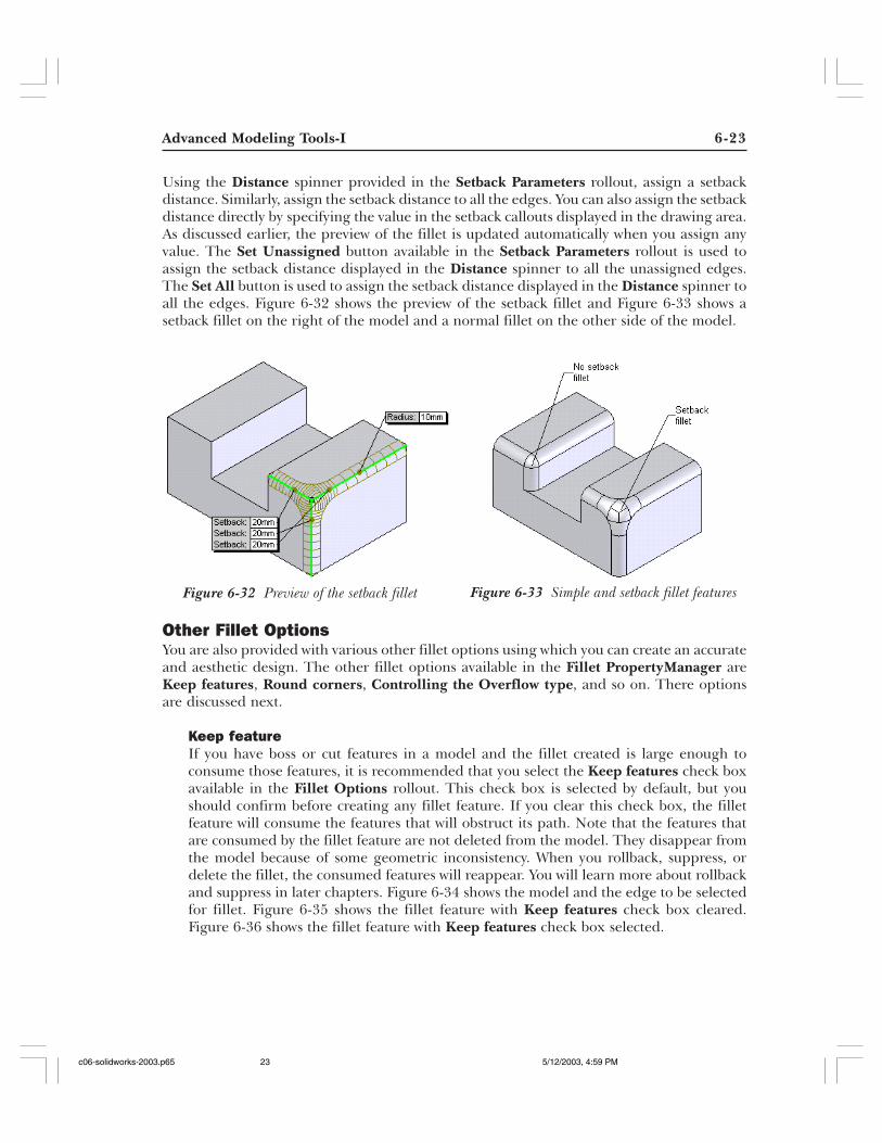
Using the Distance spinner provided in the Setback Parameters rollout, assign a setbackdistance. Similarly, assign the setback distance to all the edges. You can also assign the setbackdistance directly by specifying the value in the setback callouts displayed in the drawing area.As discussed earlier, the preview of the fillet is updated automatically when you assign anyvalue. The Set Unassigned button available in the Setback Parameters rollout is used toassign the setback distance displayed in the Distance spinner to all the unassigned edges.The Set All button is used to assign the setback distance displayed in the Distance spinner toall the edges. Figure 6-32 shows the preview of the setback fillet and Figure 6-33 shows asetback fillet on the right of the model and a normal fillet on the other side of the model.
Other Fillet OptionsYou are also provided with various other fillet options using which you can create an accurateand aesthetic design. The other fillet options available in the Fillet PropertyManager areKeep features, Round corners, Controlling the Overflow type, and so on. There optionsare discussed next.
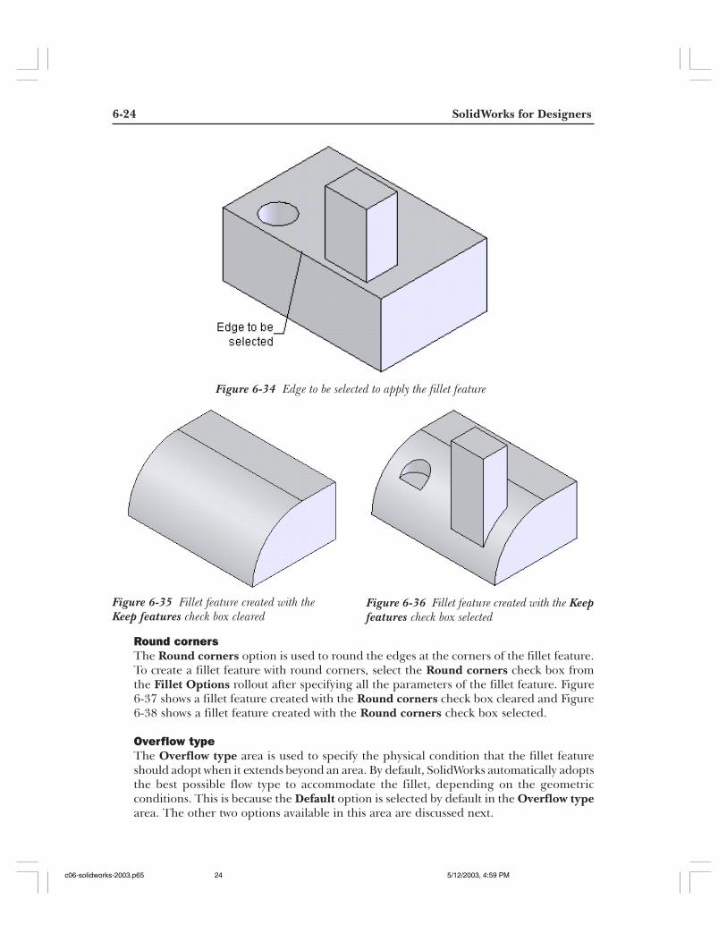
Keep featureIf you have boss or cut features in a model and the fillet created is large enough toconsume those features, it is recommended that you select the Keep features check boxavailable in the Fillet Options rollout. This check box is selected by default, but youshould confirm before creating any fillet feature. If you clear this check box, the filletfeature will consume the features that will obstruct its path. Note that the features thatare consumed by the fillet feature are not deleted from the model. They disappear fromthe model because of some geometric inconsistency. When you rollback, suppress, ordelete the fillet, the consumed features will reappear. You will learn more about rollbackand suppress in later chapters. Figure 6-34 shows the model and the edge to be selectedfor fillet. Figure 6-35 shows the fillet feature with Keep features check box cleared.Figure 6-36 shows the fillet feature with Keep features check box selected.
Figure 6-32 Preview of the setback fillet Figure 6-33 Simple and setback fillet features
c06-solidworks-2003.p65 5/12/2003, 4:59 PM23
6-24 SolidWorks for Designers
Figure 6-35 Fillet feature created with theKeep features check box cleared
Figure 6-36 Fillet feature created with the Keepfeatures check box selected
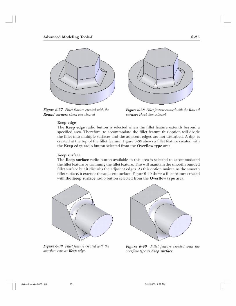
Round cornersThe Round corners option is used to round the edges at the corners of the fillet feature.To create a fillet feature with round corners, select the Round corners check box fromthe Fillet Options rollout after specifying all the parameters of the fillet feature. Figure6-37 shows a fillet feature created with the Round corners check box cleared and Figure6-38 shows a fillet feature created with the Round corners check box selected.
Overflow typeThe Overflow type area is used to specify the physical condition that the fillet featureshould adopt when it extends beyond an area. By default, SolidWorks automatically adoptsthe best possible flow type to accommodate the fillet, depending on the geometricconditions. This is because the Default option is selected by default in the Overflow typearea. The other two options available in this area are discussed next.
Figure 6-34 Edge to be selected to apply the fillet feature
c06-solidworks-2003.p65 5/12/2003, 4:59 PM24
Advanced Modeling Tools-I 6-25
Figure 6-37 Fillet feature created with theRound corners check box cleared
Figure 6-38 Fillet feature created with the Roundcorners check box selected
Figure 6-39 Fillet feature created with theoverflow type as Keep edge
Figure 6-40 Fillet feature created with theoverflow type as Keep surface
Keep edgeThe Keep edge radio button is selected when the fillet feature extends beyond aspecified area. Therefore, to accommodate the fillet feature this option will dividethe fillet into multiple surfaces and the adjacent edges are not disturbed. A dip iscreated at the top of the fillet feature. Figure 6-39 shows a fillet feature created withthe Keep edge radio button selected from the Overflow type area.
Keep surfaceThe Keep surface radio button available in this area is selected to accommodatedthe fillet feature by trimming the fillet feature. This will maintain the smooth roundedfillet surface but it disturbs the adjacent edges. As this option maintains the smoothfillet surface, it extends the adjacent surface. Figure 6-40 shows a fillet feature createdwith the Keep surface radio button selected from the Overflow type area.
c06-solidworks-2003.p65 5/12/2003, 4:59 PM25
6-26 SolidWorks for Designers
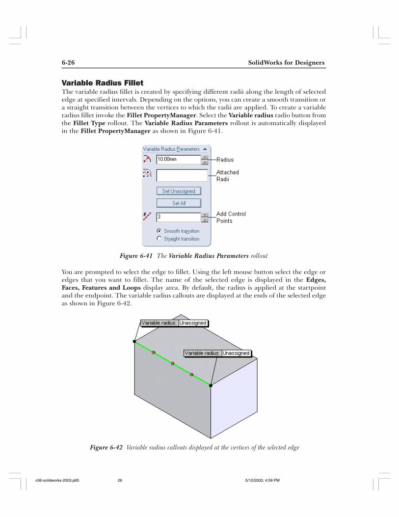
Variable Radius FilletThe variable radius fillet is created by specifying different radii along the length of selectededge at specified intervals. Depending on the options, you can create a smooth transition ora straight transition between the vertices to which the radii are applied. To create a variableradius fillet invoke the Fillet PropertyManager. Select the Variable radius radio button fromthe Fillet Type rollout. The Variable Radius Parameters rollout is automatically displayedin the Fillet PropertyManager as shown in Figure 6-41.
You are prompted to select the edge to fillet. Using the left mouse button select the edge oredges that you want to fillet. The name of the selected edge is displayed in the Edges,Faces, Features and Loops display area. By default, the radius is applied at the startpointand the endpoint. The variable radius callouts are displayed at the ends of the selected edgeas shown in Figure 6-42.
Figure 6-41 The Variable Radius Parameters rollout
Figure 6-42 Variable radius callouts displayed at the vertices of the selected edge
c06-solidworks-2003.p65 5/12/2003, 4:59 PM26
Advanced Modeling Tools-I 6-27
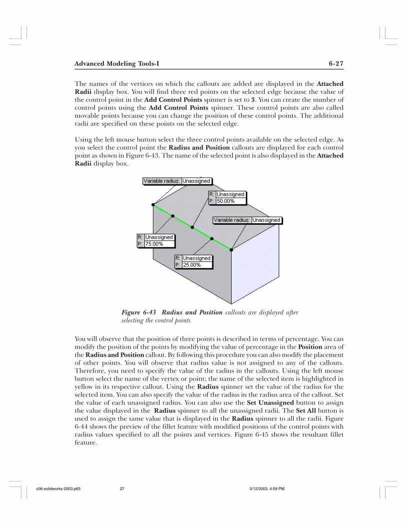
The names of the vertices on which the callouts are added are displayed in the AttachedRadii display box. You will find three red points on the selected edge because the value ofthe control point in the Add Control Points spinner is set to 3. You can create the number ofcontrol points using the Add Control Points spinner. These control points are also calledmovable points because you can change the position of these control points. The additionalradii are specified on these points on the selected edge.
Using the left mouse button select the three control points available on the selected edge. Asyou select the control point the Radius and Position callouts are displayed for each controlpoint as shown in Figure 6-43. The name of the selected point is also displayed in the AttachedRadii display box.
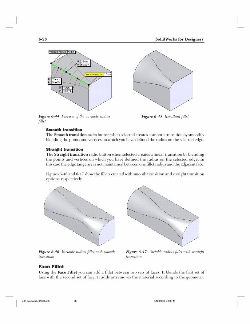
You will observe that the position of three points is described in terms of percentage. You canmodify the position of the points by modifying the value of percentage in the Position area ofthe Radius and Position callout. By following this procedure you can also modify the placementof other points. You will observe that radius value is not assigned to any of the callouts.Therefore, you need to specify the value of the radius in the callouts. Using the left mousebutton select the name of the vertex or point; the name of the selected item is highlighted inyellow in its respective callout. Using the Radius spinner set the value of the radius for theselected item. You can also specify the value of the radius in the radius area of the callout. Setthe value of each unassigned radius. You can also use the Set Unassigned button to assignthe value displayed in the Radius spinner to all the unassigned radii. The Set All button isused to assign the same value that is displayed in the Radius spinner to all the radii. Figure6-44 shows the preview of the fillet feature with modified positions of the control points withradius values specified to all the points and vertices. Figure 6-45 shows the resultant filletfeature.
Figure 6-43 Radius and Position callouts are displayed afterselecting the control points
c06-solidworks-2003.p65 5/12/2003, 4:59 PM27
6-28 SolidWorks for Designers
Figure 6-44 Preview of the variable radiusfillet
Figure 6-45 Resultant fillet
Smooth transitionThe Smooth transition radio button when selected creates a smooth transition by smoothlyblending the points and vertices on which you have defined the radius on the selected edge.
Straight transitionThe Straight transition radio button when selected creates a linear transition by blendingthe points and vertices on which you have defined the radius on the selected edge. Inthis case the edge tangency is not maintained between one fillet radius and the adjacent face.
Figures 6-46 and 6-47 show the fillets created with smooth transition and straight transitionoptions respectively.
Face FilletUsing the Face Fillet you can add a fillet between two sets of faces. It blends the first set offace with the second set of face. It adds or removes the material according to the geometric
Figure 6-46 Variable radius fillet with smoothtransition
Figure 6-47 Variable radius fillet with straighttransition
c06-solidworks-2003.p65 5/12/2003, 4:59 PM28
Advanced Modeling Tools-I 6-29
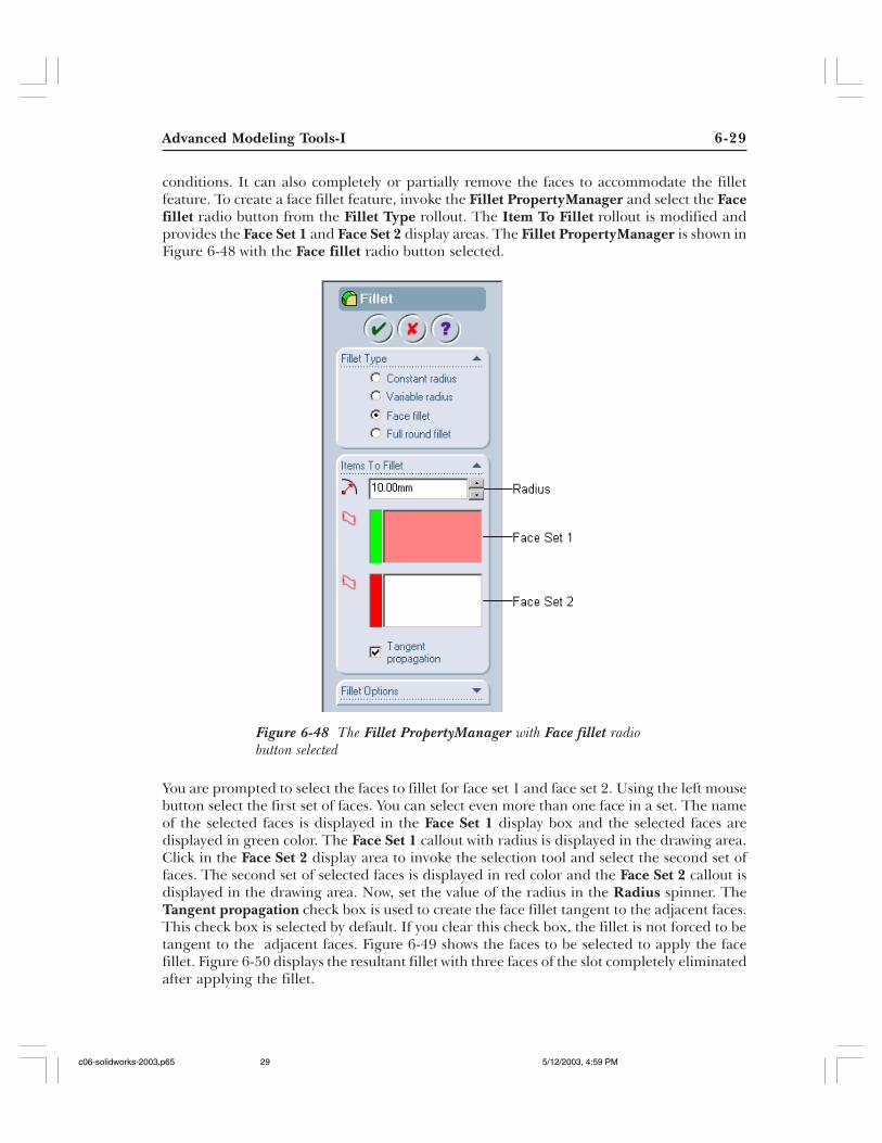
conditions. It can also completely or partially remove the faces to accommodate the filletfeature. To create a face fillet feature, invoke the Fillet PropertyManager and select the Facefillet radio button from the Fillet Type rollout. The Item To Fillet rollout is modified andprovides the Face Set 1 and Face Set 2 display areas. The Fillet PropertyManager is shown inFigure 6-48 with the Face fillet radio button selected.
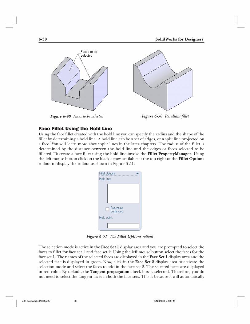
You are prompted to select the faces to fillet for face set 1 and face set 2. Using the left mousebutton select the first set of faces. You can select even more than one face in a set. The nameof the selected faces is displayed in the Face Set 1 display box and the selected faces aredisplayed in green color. The Face Set 1 callout with radius is displayed in the drawing area.Click in the Face Set 2 display area to invoke the selection tool and select the second set offaces. The second set of selected faces is displayed in red color and the Face Set 2 callout isdisplayed in the drawing area. Now, set the value of the radius in the Radius spinner. TheTangent propagation check box is used to create the face fillet tangent to the adjacent faces.This check box is selected by default. If you clear this check box, the fillet is not forced to betangent to the adjacent faces. Figure 6-49 shows the faces to be selected to apply the facefillet. Figure 6-50 displays the resultant fillet with three faces of the slot completely eliminatedafter applying the fillet.
Figure 6-48 The Fillet PropertyManager with Face fillet radiobutton selected
c06-solidworks-2003.p65 5/12/2003, 4:59 PM29
6-30 SolidWorks for Designers
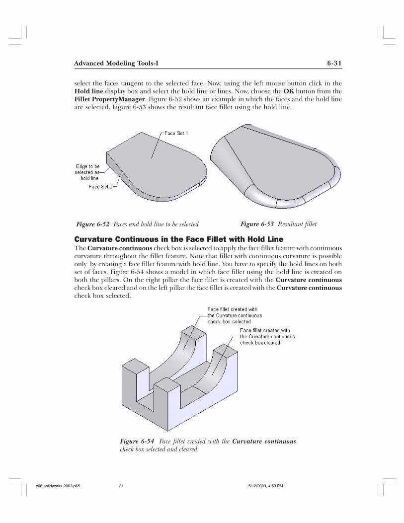
Face Fillet Using the Hold LineUsing the face fillet created with the hold line you can specify the radius and the shape of thefillet by determining a hold line. A hold line can be a set of edges, or a split line projected ona face. You will learn more about split lines in the later chapters. The radius of the fillet isdetermined by the distance between the hold line and the edges or faces selected to befilleted. To create a face fillet using the hold line invoke the Fillet PropertyManager. Usingthe left mouse button click on the black arrow available at the top right of the Fillet Optionsrollout to display the rollout as shown in Figure 6-51.
The selection mode is active in the Face Set 1 display area and you are prompted to select thefaces to fillet for face set 1 and face set 2. Using the left mouse button select the faces for theface set 1. The names of the selected faces are displayed in the Face Set 1 display area and theselected face is displayed in green. Now, click in the Face Set 2 display area to activate theselection mode and select the faces to add in the face set 2. The selected faces are displayedin red color. By default, the Tangent propagation check box is selected. Therefore, you donot need to select the tangent faces in both the face sets. This is because it will automatically
Figure 6-49 Faces to be selected Figure 6-50 Resultant fillet
Figure 6-51 The Fillet Options rollout
c06-solidworks-2003.p65 5/12/2003, 4:59 PM30
Advanced Modeling Tools-I 6-31
select the faces tangent to the selected face. Now, using the left mouse button click in theHold line display box and select the hold line or lines. Now, choose the OK button from theFillet PropertyManager. Figure 6-52 shows an example in which the faces and the hold lineare selected. Figure 6-53 shows the resultant face fillet using the hold line.
Curvature Continuous in the Face Fillet with Hold LineThe Curvature continuous check box is selected to apply the face fillet feature with continuouscurvature throughout the fillet feature. Note that fillet with continuous curvature is possibleonly by creating a face fillet feature with hold line. You have to specify the hold lines on bothset of faces. Figure 6-54 shows a model in which face fillet using the hold line is created onboth the pillars. On the right pillar the face fillet is created with the Curvature continuouscheck box cleared and on the left pillar the face fillet is created with the Curvature continuouscheck box selected.
Figure 6-52 Faces and hold line to be selected Figure 6-53 Resultant fillet
Figure 6-54 Face fillet created with the Curvature continuouscheck box selected and cleared
c06-solidworks-2003.p65 5/12/2003, 4:59 PM31
6-32 SolidWorks for Designers
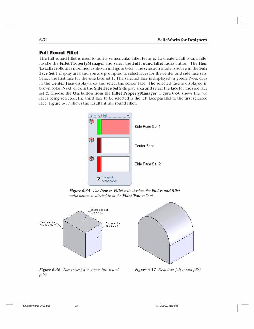
Full Round FilletThe full round fillet is used to add a semicircular fillet feature. To create a full round filletinvoke the Fillet PropertyManager and select the Full round fillet radio button. The ItemTo Fillet rollout is modified as shown in Figure 6-55. The selection mode is active in the SideFace Set 1 display area and you are prompted to select faces for the center and side face sets.Select the first face for the side face set 1. The selected face is displayed in green. Now, clickin the Center Face display area and select the center face. The selected face is displayed inbrown color. Next, click in the Side Face Set 2 display area and select the face for the side faceset 2. Choose the OK button from the Fillet PropertyManager. Figure 6-56 shows the twofaces being selected; the third face to be selected is the left face parallel to the first selectedface. Figure 6-57 shows the resultant full round fillet.
Figure 6-55 The Item to Fillet rollout when the Full round filletradio button is selected from the Fillet Type rollout
Figure 6-56 Faces selected to create full roundfillet.
Figure 6-57 Resultant full round fillet
c06-solidworks-2003.p65 5/12/2003, 4:59 PM32
Advanced Modeling Tools-I 6-33
Selection MethodsAs you have learned about basic and advanced modeling tools, it is necessary for you to learnabout some selection methods using which you can increase your productivity and speed ofmodeling. The selection methods that can increase your speed of creating fillets andchamfers are discussed next.
Select OtherThe Select Other option is the most common tool to cycle through the entities for selection.This option is used when the selection is difficult in a multi-featured complex model. Beforeinvoking any other tool, select any entity and right-click to invoke the shortcut menu. Choosethe Select Other option from the shortcut menu. The select cursor is replaced by the cyclethrough cursor. Also, any one face of the model is selected and the boundary of the face ishighlighted in green. You can cycle through the other faces using the right-click and whenthe required face is selected, use the left mouse button to confirm the selection.
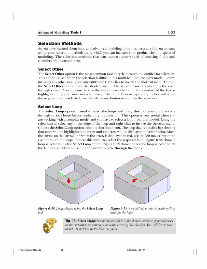
Select LoopThe Select Loop option is used to select the loops and using this tool you can also cyclethrough various loops before confirming the selection. This option is very useful when youare working with a complex model and you have to select a loop from that model. Using theselect cursor, select any of the edge of the loop and right-click to invoke the shortcut menu.Choose the Select Loop option from the short cut menu. The loop that is possible by selectingthat edge will be highlighted in green and an arrow will be displayed in yellow color. Movethe cursor on that arrow and when the arrow is displayed in red, use the left mouse button tocycle through the loops. Repeat this until you select the required loop. Figure 6-58 shows aloop selected using the Select Loop option. Figure 6-59 shows the second loop selected whenthe left mouse button is used on the arrow to cycle through the loops.
Figure 6-58 Loop selected using the Select Looptool
Figure 6-59 Second loop is selected while cyclingthrough the loops
Tip. The Select Midpoint option available in the shortcut menu is generally usedin the sketching environment or while creating 3D sketches. You will learn moreabout 3D sketches in the later chapters.
c06-solidworks-2003.p65 5/12/2003, 4:59 PM33
6-34 SolidWorks for Designers
Select TangencyThe Select Tangency option is used to automatically select the edges or faces that are tangentto the selected face. This option is available in the shortcut menu only when a face or edge istangent to the selected face or edge. For using this option select any face or edge using theselect tool and right-click to invoke the shortcut menu and choose the Select Tangencyoption from the shortcut menu.
Creating Chamfer
Chamfering is defined as a process in which the sharp edges are bevelled in order toreduce the area of stress concentration. This process also eliminates the sharp edgesand corners that are not desirable. In SolidWorks chamfer is created using the Chamfer
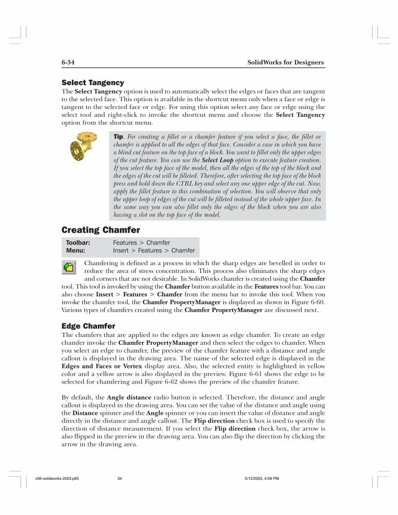
tool. This tool is invoked by using the Chamfer button available in the Features tool bar. You canalso choose Insert > Features > Chamfer from the menu bar to invoke this tool. When youinvoke the chamfer tool, the Chamfer PropertyManager is displayed as shown in Figure 6-60.Various types of chamfers created using the Chamfer PropertyManager are discussed next.
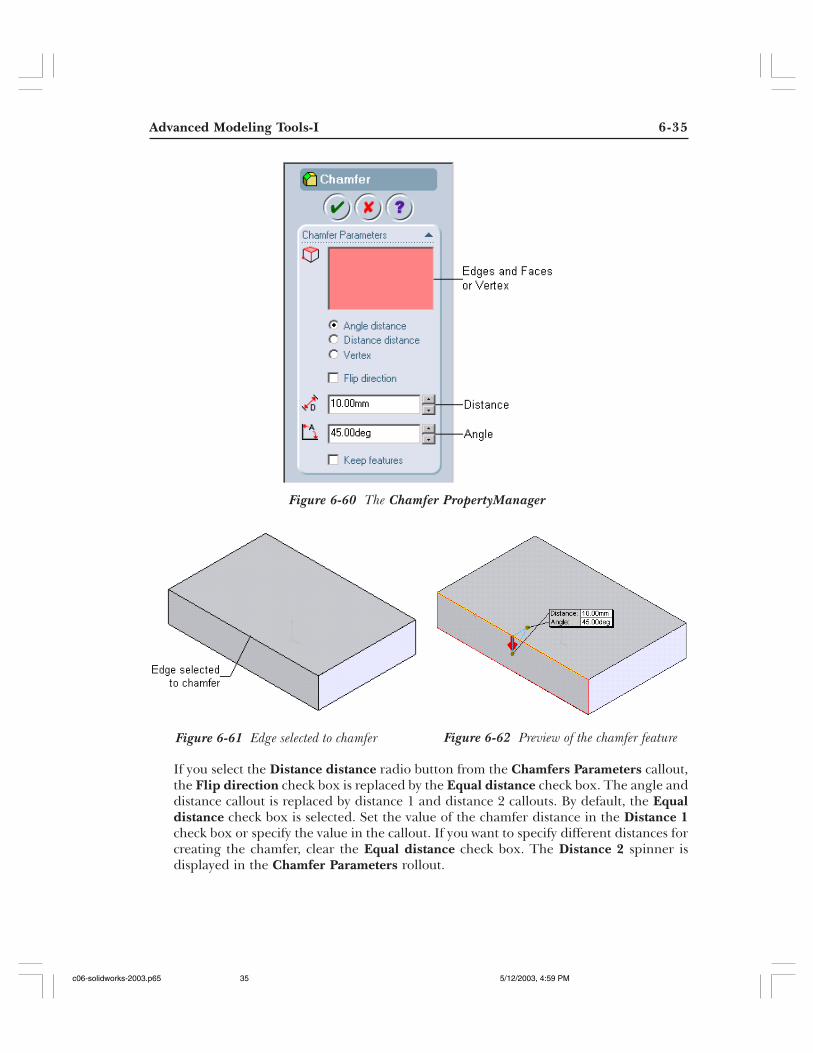
Edge ChamferThe chamfers that are applied to the edges are known as edge chamfer. To create an edgechamfer invoke the Chamfer PropertyManager and then select the edges to chamfer. Whenyou select an edge to chamfer, the preview of the chamfer feature with a distance and anglecallout is displayed in the drawing area. The name of the selected edge is displayed in theEdges and Faces or Vertex display area. Also, the selected entity is highlighted in yellowcolor and a yellow arrow is also displayed in the preview. Figure 6-61 shows the edge to beselected for chamfering and Figure 6-62 shows the preview of the chamfer feature.
By default, the Angle distance radio button is selected. Therefore, the distance and anglecallout is displayed in the drawing area. You can set the value of the distance and angle usingthe Distance spinner and the Angle spinner or you can insert the value of distance and angledirectly in the distance and angle callout. The Flip direction check box is used to specify thedirection of distance measurement. If you select the Flip direction check box, the arrow isalso flipped in the preview in the drawing area. You can also flip the direction by clicking thearrow in the drawing area.
Tip. For creating a fillet or a chamfer feature if you select a face, the fillet orchamfer is applied to all the edges of that face. Consider a case in which you havea blind cut feature on the top face of a block. You want to fillet only the upper edgesof the cut feature. You can use the Select Loop option to execute feature creation.If you select the top face of the model, then all the edges of the top of the block andthe edges of the cut will be filleted. Therefore, after selecting the top face of the blockpress and hold down the CTRL key and select any one upper edge of the cut. Now,apply the fillet feature to this combination of selection. You will observe that onlythe upper loop of edges of the cut will be filleted instead of the whole upper face. Inthe same way you can also fillet only the edges of the block when you are alsohaving a slot on the top face of the model.
Toolbar: Features > ChamferMenu: Insert > Features > Chamfer
c06-solidworks-2003.p65 5/12/2003, 4:59 PM34
Advanced Modeling Tools-I 6-35
Figure 6-60 The Chamfer PropertyManager
Figure 6-61 Edge selected to chamfer Figure 6-62 Preview of the chamfer feature
If you select the Distance distance radio button from the Chamfers Parameters callout,the Flip direction check box is replaced by the Equal distance check box. The angle anddistance callout is replaced by distance 1 and distance 2 callouts. By default, the Equaldistance check box is selected. Set the value of the chamfer distance in the Distance 1check box or specify the value in the callout. If you want to specify different distances forcreating the chamfer, clear the Equal distance check box. The Distance 2 spinner isdisplayed in the Chamfer Parameters rollout.
c06-solidworks-2003.p65 5/12/2003, 4:59 PM35
6-36 SolidWorks for Designers
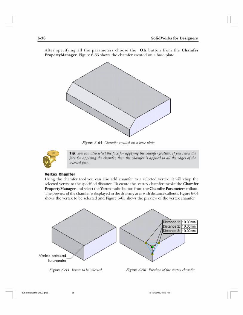
After specifying all the parameters choose the OK button from the ChamferPropertyManager. Figure 6-63 shows the chamfer created on a base plate.
Vertex ChamferUsing the chamfer tool you can also add chamfer to a selected vertex. It will chop theselected vertex to the specified distance. To create the vertex chamfer invoke the ChamferPropertyManager and select the Vertex radio button from the Chamfer Parameters rollout.The preview of the chamfer is displayed in the drawing area with distance callouts. Figure 6-64shows the vertex to be selected and Figure 6-65 shows the preview of the vertex chamfer.
Figure 6-63 Chamfer created on a base plate
Tip. You can also select the face for applying the chamfer feature. If you select theface for applying the chamfer, then the chamfer is applied to all the edges of theselected face.
Figure 6-55 Vertex to be selected Figure 6-56 Preview of the vertex chamfer
c06-solidworks-2003.p65 5/12/2003, 4:59 PM36
Advanced Modeling Tools-I 6-37
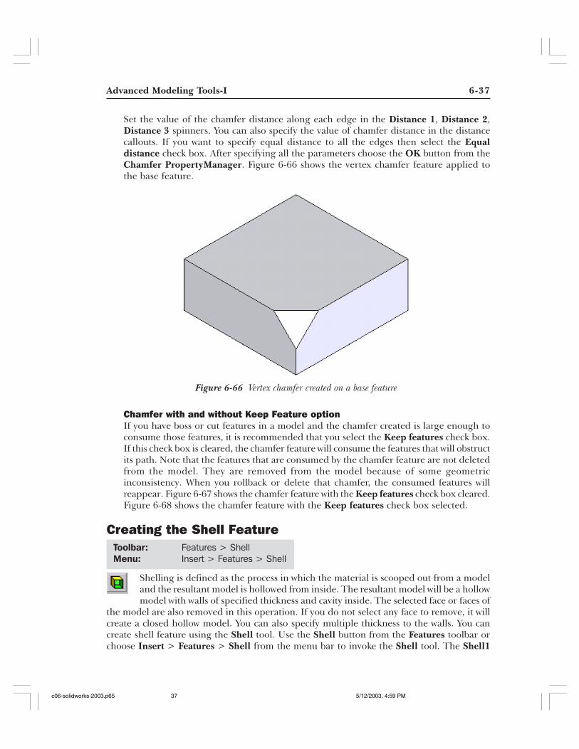
Set the value of the chamfer distance along each edge in the Distance 1, Distance 2,Distance 3 spinners. You can also specify the value of chamfer distance in the distancecallouts. If you want to specify equal distance to all the edges then select the Equaldistance check box. After specifying all the parameters choose the OK button from theChamfer PropertyManager. Figure 6-66 shows the vertex chamfer feature applied tothe base feature.
Chamfer with and without Keep Feature optionIf you have boss or cut features in a model and the chamfer created is large enough toconsume those features, it is recommended that you select the Keep features check box.If this check box is cleared, the chamfer feature will consume the features that will obstructits path. Note that the features that are consumed by the chamfer feature are not deletedfrom the model. They are removed from the model because of some geometricinconsistency. When you rollback or delete that chamfer, the consumed features willreappear. Figure 6-67 shows the chamfer feature with the Keep features check box cleared.Figure 6-68 shows the chamfer feature with the Keep features check box selected.
Creating the Shell Feature
Shelling is defined as the process in which the material is scooped out from a modeland the resultant model is hollowed from inside. The resultant model will be a hollowmodel with walls of specified thickness and cavity inside. The selected face or faces of
the model are also removed in this operation. If you do not select any face to remove, it willcreate a closed hollow model. You can also specify multiple thickness to the walls. You cancreate shell feature using the Shell tool. Use the Shell button from the Features toolbar orchoose Insert > Features > Shell from the menu bar to invoke the Shell tool. The Shell1
Figure 6-66 Vertex chamfer created on a base feature
Toolbar: Features > ShellMenu: Insert > Features > Shell
c06-solidworks-2003.p65 5/12/2003, 4:59 PM37
6-38 SolidWorks for Designers
Figure 6-67 Chamfer feature with Keep fea-tures check box cleared
Figure 6-68 Chamfer feature with Keep featurescheck box selected
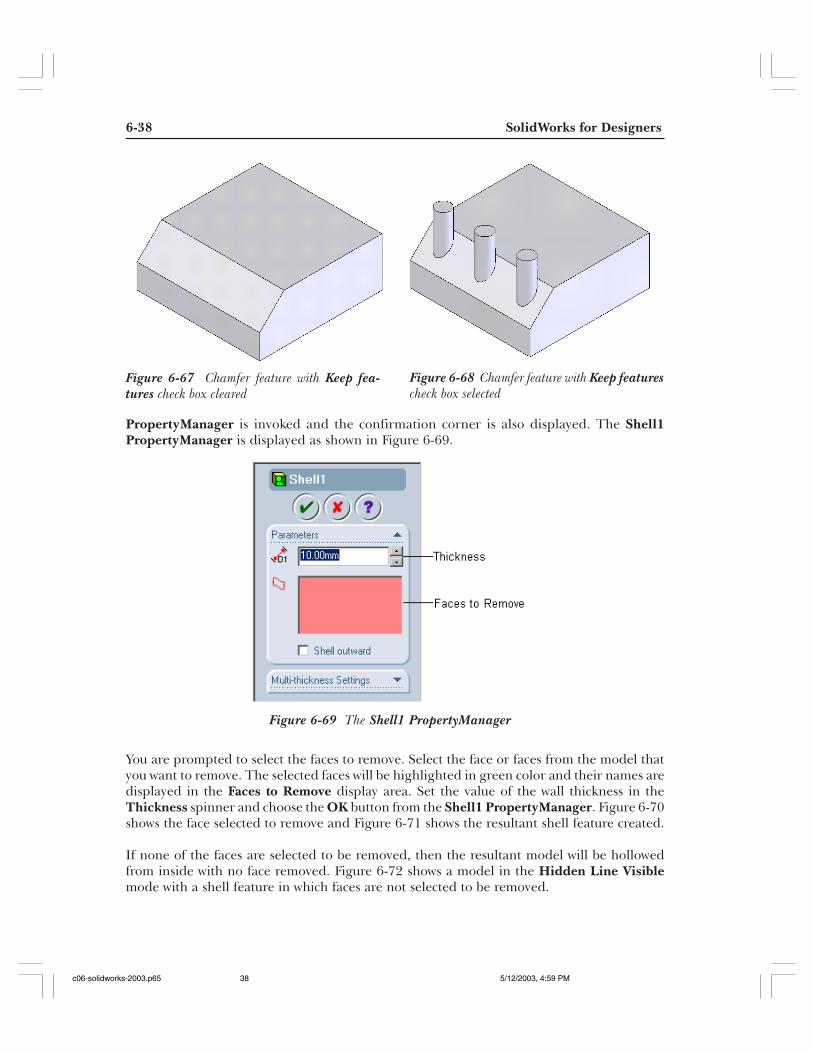
PropertyManager is invoked and the confirmation corner is also displayed. The Shell1PropertyManager is displayed as shown in Figure 6-69.
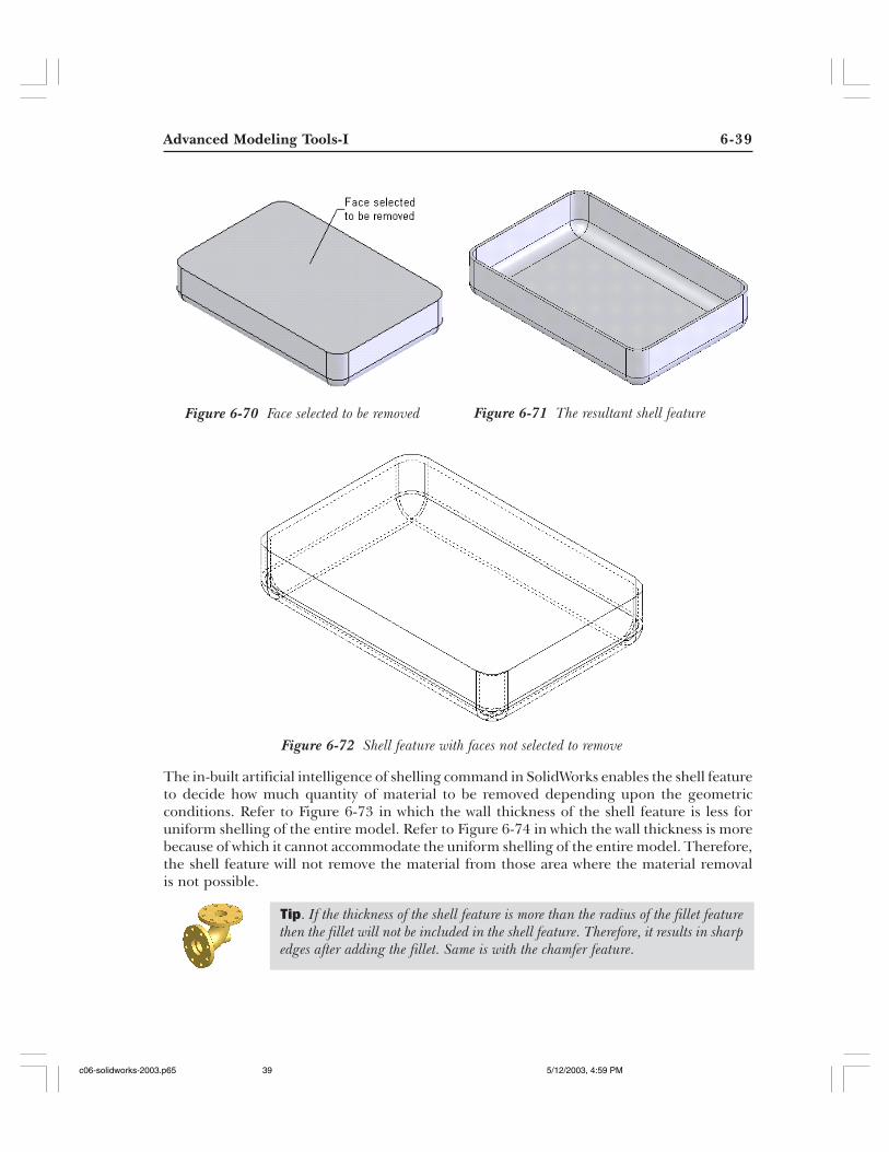
You are prompted to select the faces to remove. Select the face or faces from the model thatyou want to remove. The selected faces will be highlighted in green color and their names aredisplayed in the Faces to Remove display area. Set the value of the wall thickness in theThickness spinner and choose the OK button from the Shell1 PropertyManager. Figure 6-70shows the face selected to remove and Figure 6-71 shows the resultant shell feature created.
If none of the faces are selected to be removed, then the resultant model will be hollowedfrom inside with no face removed. Figure 6-72 shows a model in the Hidden Line Visiblemode with a shell feature in which faces are not selected to be removed.
Figure 6-69 The Shell1 PropertyManager
c06-solidworks-2003.p65 5/12/2003, 4:59 PM38
Advanced Modeling Tools-I 6-39
Figure 6-70 Face selected to be removed Figure 6-71 The resultant shell feature
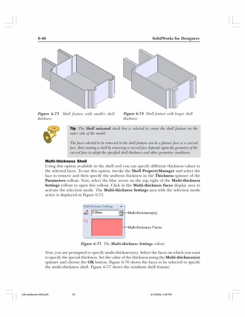
The in-built artificial intelligence of shelling command in SolidWorks enables the shell featureto decide how much quantity of material to be removed depending upon the geometricconditions. Refer to Figure 6-73 in which the wall thickness of the shell feature is less foruniform shelling of the entire model. Refer to Figure 6-74 in which the wall thickness is morebecause of which it cannot accommodate the uniform shelling of the entire model. Therefore,the shell feature will not remove the material from those area where the material removalis not possible.
Figure 6-72 Shell feature with faces not selected to remove
Tip. If the thickness of the shell feature is more than the radius of the fillet featurethen the fillet will not be included in the shell feature. Therefore, it results in sharpedges after adding the fillet. Same is with the chamfer feature.
c06-solidworks-2003.p65 5/12/2003, 4:59 PM39
6-40 SolidWorks for Designers
Figure 6-73 Shell feature with smaller shellthickness
Figure 6-74 Shell feature with larger shellthickness
Multi-thickness ShellUsing this option available in the shell tool you can specify different thickness values tothe selected faces. To use this option, invoke the Shell PropertyManager and select theface to remove and then specify the uniform thickness in the Thickness spinner of theParameters rollout. Now, select the blue arrow on the top right of the Multi-thicknessSettings rollout to open this rollout. Click in the Multi-thickness Faces display area toactivate the selection mode. The Multi-thickness Settings area with the selection modeactive is displayed in Figure 6-75.
Now, you are prompted to specify multi-thickness(es). Select the faces on which you wantto specify the special thickness. Set the value of the thickness using the Multi-thickness(es)spinner and choose the OK button. Figure 6-76 shows the faces to be selected to specifythe multi-thickness shell. Figure 6-77 shows the resultant shell feature.
Tip. The Shell outward check box is selected to create the shell feature on theouter side of the model.
The faces selected to be removed in the shell feature can be a planar face or a curvedface. But creating a shell by removing a curved face depends upon the geometry of thecurved face to adopt the specified shell thickness and other geometric conditions.
Figure 6-75 The Multi-thickness Settings rollout
c06-solidworks-2003.p65 5/12/2003, 4:59 PM40
Advanced Modeling Tools-I 6-41
TUTORIALS
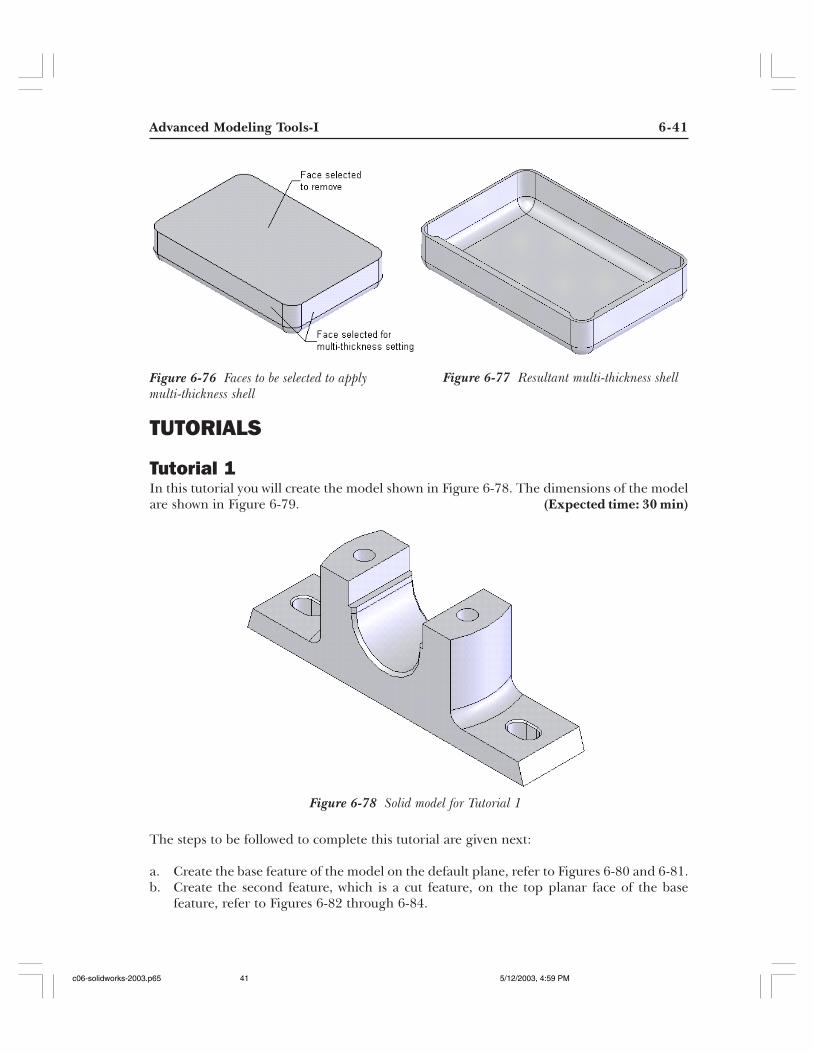
Tutorial 1In this tutorial you will create the model shown in Figure 6-78. The dimensions of the modelare shown in Figure 6-79. (Expected time: 30 min)
The steps to be followed to complete this tutorial are given next:
a. Create the base feature of the model on the default plane, refer to Figures 6-80 and 6-81.b. Create the second feature, which is a cut feature, on the top planar face of the base
feature, refer to Figures 6-82 through 6-84.
Figure 6-76 Faces to be selected to applymulti-thickness shell
Figure 6-77 Resultant multi-thickness shell
Figure 6-78 Solid model for Tutorial 1
c06-solidworks-2003.p65 5/12/2003, 4:59 PM41
6-42 SolidWorks for Designers
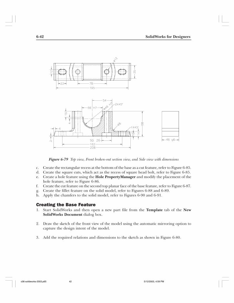
Figure 6-79 Top view, Front broken-out section view, and Side view with dimensions
c. Create the rectangular recess at the bottom of the base as a cut feature, refer to Figure 6-85.d. Create the square cuts, which act as the recess of square head bolt, refer to Figure 6-85.e. Create a hole feature using the Hole PropertyManager and modify the placement of the
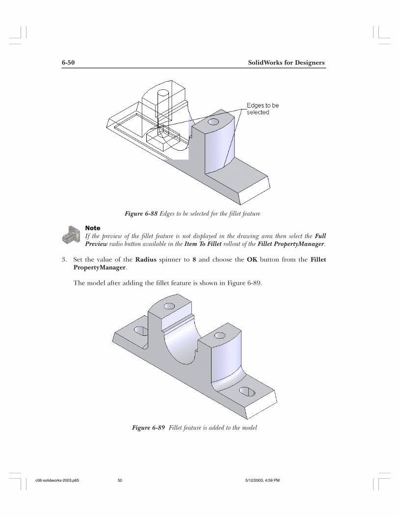
hole feature, refer to Figure 6-86.f. Create the cut feature on the second top planar face of the base feature, refer to Figure 6-87.g. Create the fillet feature on the solid model, refer to Figures 6-88 and 6-89.h. Apply the chamfers to the solid model, refer to Figures 6-90 and 6-91.
Creating the Base Feature1. Start SolidWorks and then open a new part file from the Template tab of the New
SolidWorks Document dialog box.
2. Draw the sketch of the front view of the model using the automatic mirroring option tocapture the design intent of the model.
3. Add the required relations and dimensions to the sketch as shown in Figure 6-80.
c06-solidworks-2003.p65 5/12/2003, 4:59 PM42
Advanced Modeling Tools-I 6-43
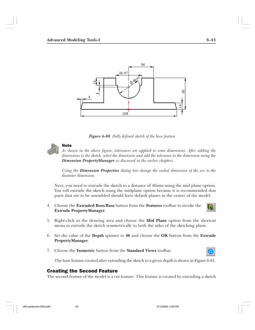
NoteAs shown in the above figure, tolerances are applied to some dimensions. After adding thedimensions to the sketch, select the dimension and add the tolerance to the dimension using theDimension PropertyManager as discussed in the earlier chapters.
Using the Dimension Properties dialog box change the radial dimension of the arc to thediameter dimension.
Next, you need to extrude the sketch to a distance of 46mm using the mid plane option.You will extrude the sketch using the midplane option because it is recommended thatparts that are to be assembled should have default planes in the center of the model.
4. Choose the Extruded Boss/Base button from the Features toolbar to invoke theExtrude PropertyManager.
5. Right-click in the drawing area and choose the Mid Plane option from the shortcutmenu to extrude the sketch symmetrically to both the sides of the sketching plane.
6. Set the value of the Depth spinner to 46 and choose the OK button from the ExtrudePropertyManager.
7. Choose the Isometric button from the Standard Views toolbar.
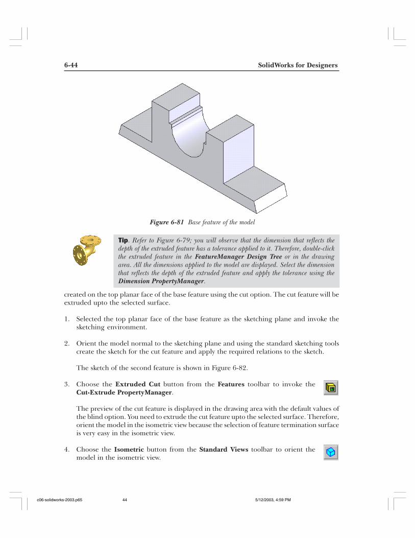
The base feature created after extruding the sketch to a given depth is shown in Figure 6-81.
Creating the Second FeatureThe second feature of the model is a cut feature. This feature is created by extruding a sketch
Figure 6-80 Fully defined sketch of the base feature
c06-solidworks-2003.p65 5/12/2003, 4:59 PM43
6-44 SolidWorks for Designers
Figure 6-81 Base feature of the model
created on the top planar face of the base feature using the cut option. The cut feature will beextruded upto the selected surface.
1. Selected the top planar face of the base feature as the sketching plane and invoke thesketching environment.
2. Orient the model normal to the sketching plane and using the standard sketching toolscreate the sketch for the cut feature and apply the required relations to the sketch.
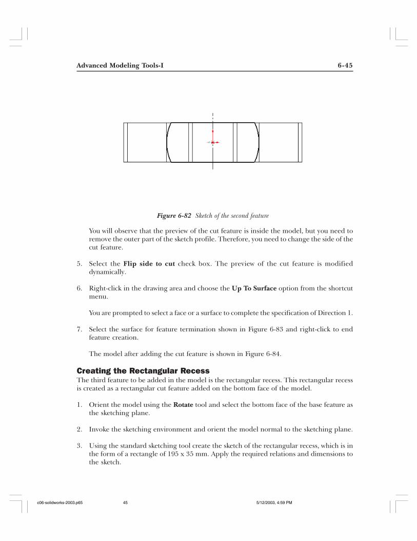
The sketch of the second feature is shown in Figure 6-82.
3. Choose the Extruded Cut button from the Features toolbar to invoke theCut-Extrude PropertyManager.
The preview of the cut feature is displayed in the drawing area with the default values ofthe blind option. You need to extrude the cut feature upto the selected surface. Therefore,orient the model in the isometric view because the selection of feature termination surfaceis very easy in the isometric view.
4. Choose the Isometric button from the Standard Views toolbar to orient themodel in the isometric view.
Tip. Refer to Figure 6-79; you will observe that the dimension that reflects thedepth of the extruded feature has a tolerance applied to it. Therefore, double-clickthe extruded feature in the FeatureManager Design Tree or in the drawingarea. All the dimensions applied to the model are displayed. Select the dimensionthat reflects the depth of the extruded feature and apply the tolerance using theDimension PropertyManager.
c06-solidworks-2003.p65 5/12/2003, 4:59 PM44
Advanced Modeling Tools-I 6-45
Figure 6-82 Sketch of the second feature
You will observe that the preview of the cut feature is inside the model, but you need toremove the outer part of the sketch profile. Therefore, you need to change the side of thecut feature.
5. Select the Flip side to cut check box. The preview of the cut feature is modifieddynamically.
6. Right-click in the drawing area and choose the Up To Surface option from the shortcutmenu.
You are prompted to select a face or a surface to complete the specification of Direction 1.
7. Select the surface for feature termination shown in Figure 6-83 and right-click to endfeature creation.
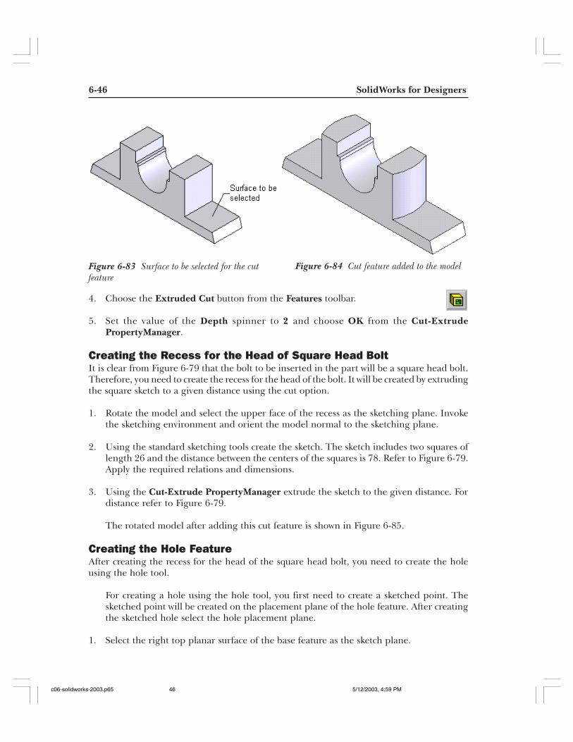
The model after adding the cut feature is shown in Figure 6-84.
Creating the Rectangular RecessThe third feature to be added in the model is the rectangular recess. This rectangular recessis created as a rectangular cut feature added on the bottom face of the model.
1. Orient the model using the Rotate tool and select the bottom face of the base feature asthe sketching plane.
2. Invoke the sketching environment and orient the model normal to the sketching plane.
3. Using the standard sketching tool create the sketch of the rectangular recess, which is inthe form of a rectangle of 195 x 35 mm. Apply the required relations and dimensions tothe sketch.
c06-solidworks-2003.p65 5/12/2003, 4:59 PM45
6-46 SolidWorks for Designers
Figure 6-83 Surface to be selected for the cutfeature
Figure 6-84 Cut feature added to the model
4. Choose the Extruded Cut button from the Features toolbar.
5. Set the value of the Depth spinner to 2 and choose OK from the Cut-ExtrudePropertyManager.
Creating the Recess for the Head of Square Head BoltIt is clear from Figure 6-79 that the bolt to be inserted in the part will be a square head bolt.Therefore, you need to create the recess for the head of the bolt. It will be created by extrudingthe square sketch to a given distance using the cut option.
1. Rotate the model and select the upper face of the recess as the sketching plane. Invokethe sketching environment and orient the model normal to the sketching plane.
2. Using the standard sketching tools create the sketch. The sketch includes two squares oflength 26 and the distance between the centers of the squares is 78. Refer to Figure 6-79.Apply the required relations and dimensions.
3. Using the Cut-Extrude PropertyManager extrude the sketch to the given distance. Fordistance refer to Figure 6-79.
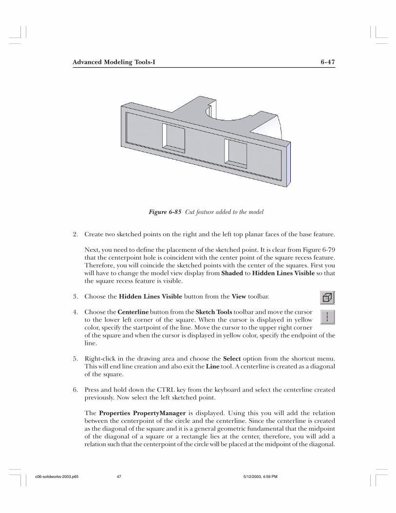
The rotated model after adding this cut feature is shown in Figure 6-85.
Creating the Hole FeatureAfter creating the recess for the head of the square head bolt, you need to create the holeusing the hole tool.
For creating a hole using the hole tool, you first need to create a sketched point. Thesketched point will be created on the placement plane of the hole feature. After creatingthe sketched hole select the hole placement plane.
1. Select the right top planar surface of the base feature as the sketch plane.
c06-solidworks-2003.p65 5/12/2003, 4:59 PM46
Advanced Modeling Tools-I 6-47
Figure 6-85 Cut feature added to the model
2. Create two sketched points on the right and the left top planar faces of the base feature.
Next, you need to define the placement of the sketched point. It is clear from Figure 6-79that the centerpoint hole is coincident with the center point of the square recess feature.Therefore, you will coincide the sketched points with the center of the squares. First youwill have to change the model view display from Shaded to Hidden Lines Visible so thatthe square recess feature is visible.
3. Choose the Hidden Lines Visible button from the View toolbar.
4. Choose the Centerline button from the Sketch Tools toolbar and move the cursorto the lower left corner of the square. When the cursor is displayed in yellowcolor, specify the startpoint of the line. Move the cursor to the upper right cornerof the square and when the cursor is displayed in yellow color, specify the endpoint of theline.
5. Right-click in the drawing area and choose the Select option from the shortcut menu.This will end line creation and also exit the Line tool. A centerline is created as a diagonalof the square.
6. Press and hold down the CTRL key from the keyboard and select the centerline createdpreviously. Now select the left sketched point.
The Properties PropertyManager is displayed. Using this you will add the relationbetween the centerpoint of the circle and the centerline. Since the centerline is createdas the diagonal of the square and it is a general geometric fundamental that the midpointof the diagonal of a square or a rectangle lies at the center, therefore, you will add arelation such that the centerpoint of the circle will be placed at the midpoint of the diagonal.
c06-solidworks-2003.p65 5/12/2003, 4:59 PM47
6-48 SolidWorks for Designers
7. Choose the Midpoint button from the Add Relations rollout of the PropertiesPropertyManager. Choose the OK button from the Properties PropertyManager.
8. Similarly, create the diagonal centerline coincident to the right square. Add the midpointrelation between the centerline and the sketched point.
9. Exit the sketcher environment and change the model display mode to shaded. Select theright top planar surface of the base feature as the placement plane for the hole feature.
As you select the placement plane, the Simple Hole option is enabled in the menu bar.
10. Choose Insert > Features >Hole > Simple Hole from the menu bar to invoke theHole PropertyManager.
As you invoke the Hole PropertyManager the preview of the hole feature with defaultsettings is displayed in the drawing area. The confirmation corner is also displayed.
11. Right-click in the drawing area and choose the Through All option from the shortcutmenu to define feature termination.
12. Set the value of the Hole Diameter spinner to 12 and choose the OK button from theHole PropertyManager.
13. Select the centerpoint of the hole and drag the cursor to the right sketched point. Releasethe left mouse button when the cursor turns yellow in color.
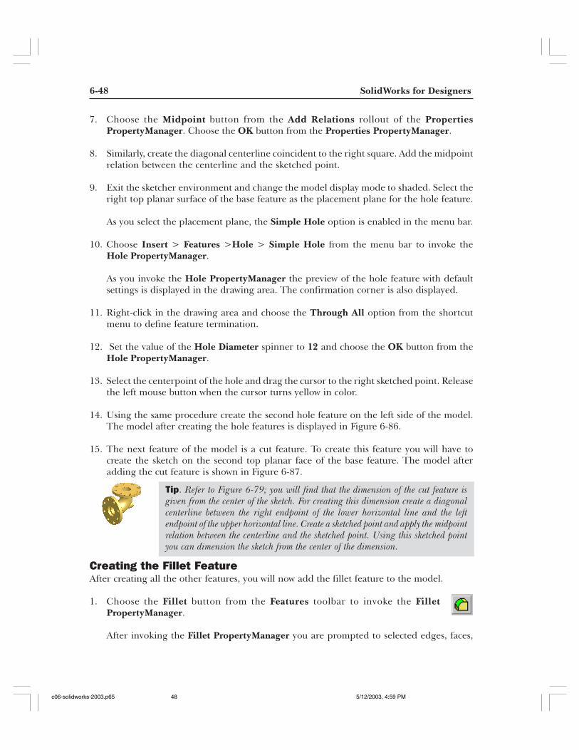
14. Using the same procedure create the second hole feature on the left side of the model.The model after creating the hole features is displayed in Figure 6-86.
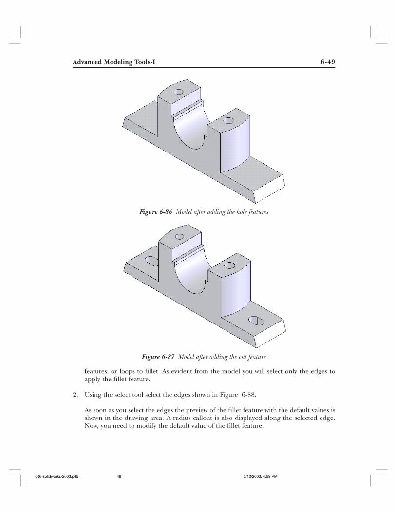
15. The next feature of the model is a cut feature. To create this feature you will have tocreate the sketch on the second top planar face of the base feature. The model afteradding the cut feature is shown in Figure 6-87.
Creating the Fillet FeatureAfter creating all the other features, you will now add the fillet feature to the model.
1. Choose the Fillet button from the Features toolbar to invoke the FilletPropertyManager.
After invoking the Fillet PropertyManager you are prompted to selected edges, faces,
Tip. Refer to Figure 6-79; you will find that the dimension of the cut feature isgiven from the center of the sketch. For creating this dimension create a diagonalcenterline between the right endpoint of the lower horizontal line and the leftendpoint of the upper horizontal line. Create a sketched point and apply the midpointrelation between the centerline and the sketched point. Using this sketched pointyou can dimension the sketch from the center of the dimension.
c06-solidworks-2003.p65 5/12/2003, 4:59 PM48
Advanced Modeling Tools-I 6-49
Figure 6-86 Model after adding the hole features
features, or loops to fillet. As evident from the model you will select only the edges toapply the fillet feature.
2. Using the select tool select the edges shown in Figure 6-88.
As soon as you select the edges the preview of the fillet feature with the default values isshown in the drawing area. A radius callout is also displayed along the selected edge.Now, you need to modify the default value of the fillet feature.
Figure 6-87 Model after adding the cut feature
c06-solidworks-2003.p65 5/12/2003, 4:59 PM49
6-50 SolidWorks for Designers
NoteIf the preview of the fillet feature is not displayed in the drawing area then select the FullPreview radio button available in the Item To Fillet rollout of the Fillet PropertyManager.
3. Set the value of the Radius spinner to 8 and choose the OK button from the FilletPropertyManager.
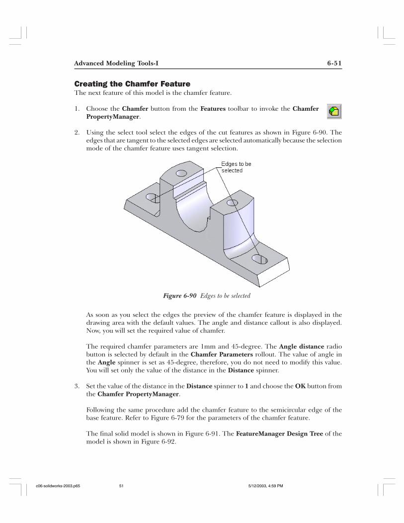
The model after adding the fillet feature is shown in Figure 6-89.
Figure 6-88 Edges to be selected for the fillet feature
Figure 6-89 Fillet feature is added to the model
c06-solidworks-2003.p65 5/12/2003, 4:59 PM50
Advanced Modeling Tools-I 6-51
Creating the Chamfer FeatureThe next feature of this model is the chamfer feature.
1. Choose the Chamfer button from the Features toolbar to invoke the ChamferPropertyManager.
2. Using the select tool select the edges of the cut features as shown in Figure 6-90. Theedges that are tangent to the selected edges are selected automatically because the selectionmode of the chamfer feature uses tangent selection.
As soon as you select the edges the preview of the chamfer feature is displayed in thedrawing area with the default values. The angle and distance callout is also displayed.Now, you will set the required value of chamfer.
The required chamfer parameters are 1mm and 45-degree. The Angle distance radiobutton is selected by default in the Chamfer Parameters rollout. The value of angle inthe Angle spinner is set as 45-degree, therefore, you do not need to modify this value.You will set only the value of the distance in the Distance spinner.
3. Set the value of the distance in the Distance spinner to 1 and choose the OK button fromthe Chamfer PropertyManager.
Following the same procedure add the chamfer feature to the semicircular edge of thebase feature. Refer to Figure 6-79 for the parameters of the chamfer feature.
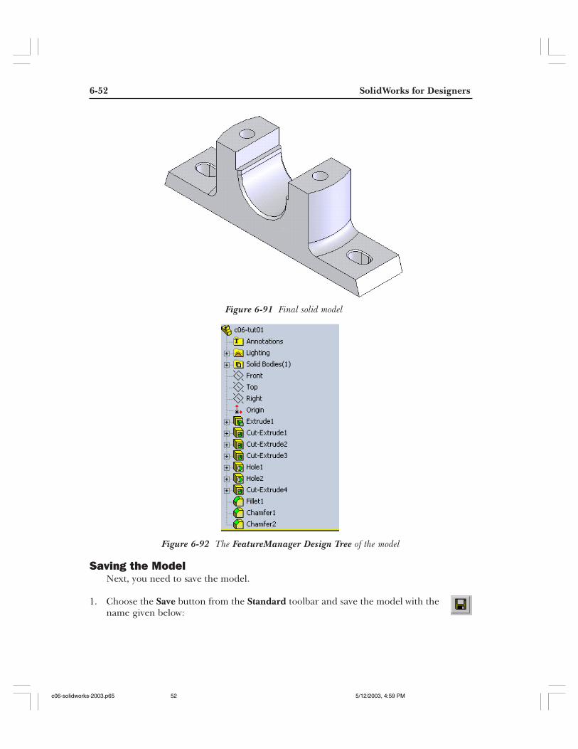
The final solid model is shown in Figure 6-91. The FeatureManager Design Tree of themodel is shown in Figure 6-92.
Figure 6-90 Edges to be selected
c06-solidworks-2003.p65 5/12/2003, 4:59 PM51
6-52 SolidWorks for Designers
Saving the ModelNext, you need to save the model.
1. Choose the Save button from the Standard toolbar and save the model with thename given below:
Figure 6-91 Final solid model
Figure 6-92 The FeatureManager Design Tree of the model
c06-solidworks-2003.p65 5/12/2003, 4:59 PM52
Advanced Modeling Tools-I 6-53
\My Documents\SolidWorks\c06\c06-tut01.SLDPRT.
2. Choose File > Close from the menu bar to close the file.
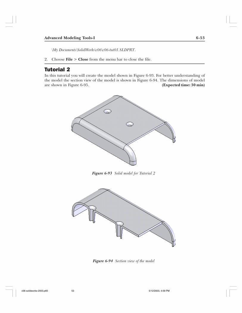
Tutorial 2In this tutorial you will create the model shown in Figure 6-93. For better understanding ofthe model the section view of the model is shown in Figure 6-94. The dimensions of modelare shown in Figure 6-95. (Expected time: 30 min)
Figure 6-93 Solid model for Tutorial 2
Figure 6-94 Section view of the model
c06-solidworks-2003.p65 5/12/2003, 4:59 PM53
6-54 SolidWorks for Designers
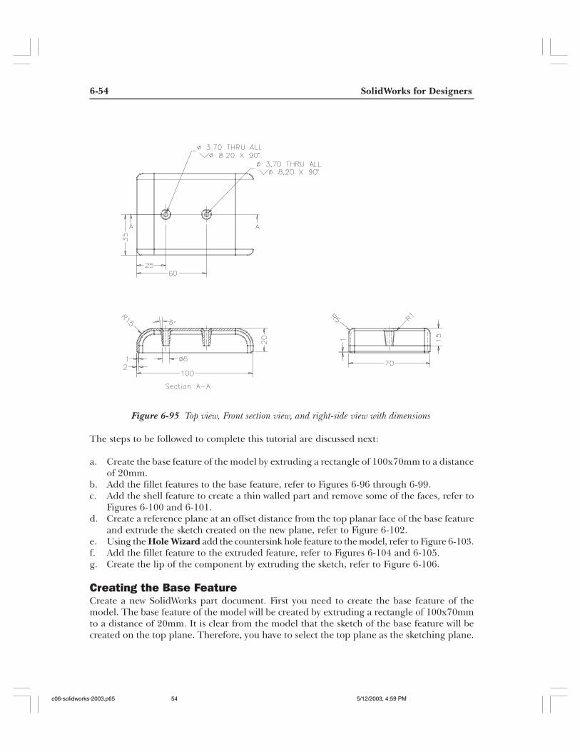
Figure 6-95 Top view, Front section view, and right-side view with dimensions
The steps to be followed to complete this tutorial are discussed next:
a. Create the base feature of the model by extruding a rectangle of 100x70mm to a distanceof 20mm.
b. Add the fillet features to the base feature, refer to Figures 6-96 through 6-99.c. Add the shell feature to create a thin walled part and remove some of the faces, refer to
Figures 6-100 and 6-101.d. Create a reference plane at an offset distance from the top planar face of the base feature
and extrude the sketch created on the new plane, refer to Figure 6-102.e. Using the Hole Wizard add the countersink hole feature to the model, refer to Figure 6-103.f. Add the fillet feature to the extruded feature, refer to Figures 6-104 and 6-105.g. Create the lip of the component by extruding the sketch, refer to Figure 6-106.
Creating the Base FeatureCreate a new SolidWorks part document. First you need to create the base feature of themodel. The base feature of the model will be created by extruding a rectangle of 100x70mmto a distance of 20mm. It is clear from the model that the sketch of the base feature will becreated on the top plane. Therefore, you have to select the top plane as the sketching plane.
c06-solidworks-2003.p65 5/12/2003, 4:59 PM54
Advanced Modeling Tools-I 6-55
1. Select the Top plane from the FeatureManager Design Tree and invoke the sketchingenvironment.
2. Orient the view normal to eye view.
3. Using the standard sketching tools create the sketch of the base feature and add therequired relations and dimensions to the sketch.
4. Choose the Extruded Boss/Base button from the Features toolbar and extrudethe base feature to a depth of 20mm.
Creating the Fillet FeaturesAfter creating the base feature, you need to add the fillet features to the model. In this modelyou will add three fillet features. Two fillet features will be added at this stage of the designprocess and the remaining one fillet feature will be added at a later stage of the design process.
1. Choose the Fillet button from the Features toolbar to invoke the FilletPropertyManager.
2. Select the edges of the model as shown in Figure 6-96.
As soon as you select the edges of the model, the preview of the fillet with the defaultvalues and the radius callout are displayed in the drawing area.
3. Set the value of the Radius spinner to 15 and choose the OK button from the FilletPropertyManager.
Figure 6-97 shows the model after adding the first fillet feature.
Now, you will add the second fillet feature to the model.
4. Invoke the Fillet PropertyManager and set the value of the Radius spinner to 5.
Figure 6-96 Edges to be selected Figure 6-97 Fillet added to the base feature
c06-solidworks-2003.p65 5/12/2003, 4:59 PM55
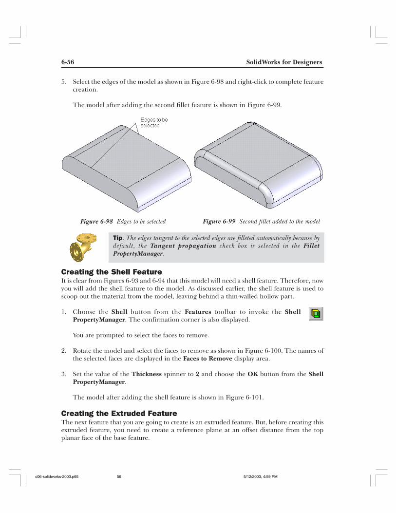
6-56 SolidWorks for Designers
5. Select the edges of the model as shown in Figure 6-98 and right-click to complete featurecreation.
The model after adding the second fillet feature is shown in Figure 6-99.
Creating the Shell FeatureIt is clear from Figures 6-93 and 6-94 that this model will need a shell feature. Therefore, nowyou will add the shell feature to the model. As discussed earlier, the shell feature is used toscoop out the material from the model, leaving behind a thin-walled hollow part.
1. Choose the Shell button from the Features toolbar to invoke the ShellPropertyManager. The confirmation corner is also displayed.
You are prompted to select the faces to remove.
2. Rotate the model and select the faces to remove as shown in Figure 6-100. The names ofthe selected faces are displayed in the Faces to Remove display area.
3. Set the value of the Thickness spinner to 2 and choose the OK button from the ShellPropertyManager.
The model after adding the shell feature is shown in Figure 6-101.
Creating the Extruded FeatureThe next feature that you are going to create is an extruded feature. But, before creating thisextruded feature, you need to create a reference plane at an offset distance from the topplanar face of the base feature.
Figure 6-98 Edges to be selected Figure 6-99 Second fillet added to the model
Tip. The edges tangent to the selected edges are filleted automatically because bydefault, the Tangent propagation check box is selected in the FilletPropertyManager.
c06-solidworks-2003.p65 5/12/2003, 4:59 PM56
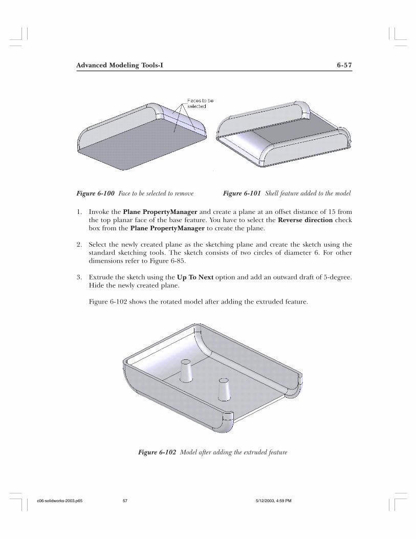
Advanced Modeling Tools-I 6-57
Figure 6-100 Face to be selected to remove Figure 6-101 Shell feature added to the model
1. Invoke the Plane PropertyManager and create a plane at an offset distance of 15 fromthe top planar face of the base feature. You have to select the Reverse direction checkbox from the Plane PropertyManager to create the plane.
2. Select the newly created plane as the sketching plane and create the sketch using thestandard sketching tools. The sketch consists of two circles of diameter 6. For otherdimensions refer to Figure 6-85.
3. Extrude the sketch using the Up To Next option and add an outward draft of 5-degree.Hide the newly created plane.
Figure 6-102 shows the rotated model after adding the extruded feature.
Figure 6-102 Model after adding the extruded feature
c06-solidworks-2003.p65 5/12/2003, 4:59 PM57
6-58 SolidWorks for Designers
Adding the Countersink Hole using the Hole WizardThe next feature that you are going to create is a countersink hole, refer to Figure 6-85. You willobserve that the hole callout displayed for countersink is generally used to accommodate theM3.5 Flat Head Machine Screw. In SolidWorks you are provided with one of the largest standardhole generating technique known as Hole Wizard. Therefore, using the Hole Wizard you willadd the standard holes to the model that can accommodate standard fasteners.
1. Rotate the model and select the top planar face of the base feature and thenchoose the Hole Wizard button from the Features toolbar.
The Hole Definition dialog box is displayed and the preview of the hole feature on theselected face with the default values is shown in the drawing area.
2. Choose the Countersink tab of the Hole Definition area.
Now, you will set the parameters to define the standard hole. The preview of the standardhole will be modified dynamically as you set the parameters for the hole feature.
3. Choose the Ansi Metric option from the Standard drop-down list.
4. Choose the Flat Head option from the Screw Type drop-down list
5. Choose the M3.5 option from the Size drop-down list and choose the Through All optionfrom the End Condition drop-down list.
6. Choose the Next button from the Hole Definition dialog box. The Hole Placementdialog box is displayed and the sketcher environment is invoked. The select cursor isreplaced by the point cursor.
7. Using the point cursor specify another point anywhere on the top planar face of the basefeature to create another hole.
Since both the placement points are not properly placed, you need to add the requiredrelations or dimensions to define the placement of the placement points. For adding therelation to fully define the placement first change the model display from Shaded toHidden Lines Visible.
8. Choose the Hidden Lines Visible button from the View toolbar to display the modelwith hidden lines visible.
9. Right-click in the drawing area and choose the Select option from the shortcut menu toinvoke the select tool.
Tip. If you select the placement plane for the placement of the hole feature beforeinvoking the Hole Definition dialog box then the placement sketch will be a 2Dsketch. If you select the placement plane after invoking the Hole Definition dialogbox then the hole placement sketch will be a 3D sketch. You will learn more about3D sketches in the later chapters.
c06-solidworks-2003.p65 5/12/2003, 4:59 PM58
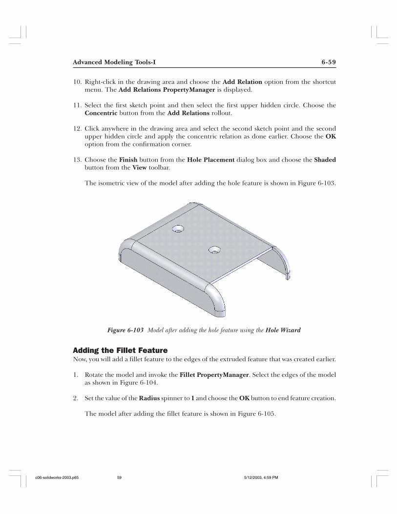
Advanced Modeling Tools-I 6-59
10. Right-click in the drawing area and choose the Add Relation option from the shortcutmenu. The Add Relations PropertyManager is displayed.
11. Select the first sketch point and then select the first upper hidden circle. Choose theConcentric button from the Add Relations rollout.
12. Click anywhere in the drawing area and select the second sketch point and the secondupper hidden circle and apply the concentric relation as done earlier. Choose the OKoption from the confirmation corner.
13. Choose the Finish button from the Hole Placement dialog box and choose the Shadedbutton from the View toolbar.
The isometric view of the model after adding the hole feature is shown in Figure 6-103.
Adding the Fillet FeatureNow, you will add a fillet feature to the edges of the extruded feature that was created earlier.
1. Rotate the model and invoke the Fillet PropertyManager. Select the edges of the modelas shown in Figure 6-104.
2. Set the value of the Radius spinner to 1 and choose the OK button to end feature creation.
The model after adding the fillet feature is shown in Figure 6-105.
Figure 6-103 Model after adding the hole feature using the Hole Wizard
c06-solidworks-2003.p65 5/12/2003, 4:59 PM59
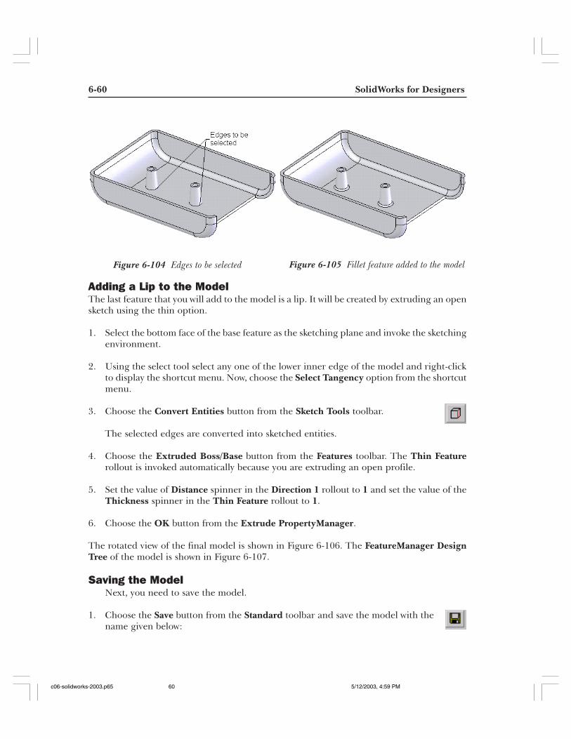
6-60 SolidWorks for Designers
Adding a Lip to the ModelThe last feature that you will add to the model is a lip. It will be created by extruding an opensketch using the thin option.
1. Select the bottom face of the base feature as the sketching plane and invoke the sketchingenvironment.
2. Using the select tool select any one of the lower inner edge of the model and right-clickto display the shortcut menu. Now, choose the Select Tangency option from the shortcutmenu.
3. Choose the Convert Entities button from the Sketch Tools toolbar.
The selected edges are converted into sketched entities.
4. Choose the Extruded Boss/Base button from the Features toolbar. The Thin Featurerollout is invoked automatically because you are extruding an open profile.
5. Set the value of Distance spinner in the Direction 1 rollout to 1 and set the value of theThickness spinner in the Thin Feature rollout to 1.
6. Choose the OK button from the Extrude PropertyManager.
The rotated view of the final model is shown in Figure 6-106. The FeatureManager DesignTree of the model is shown in Figure 6-107.
Saving the ModelNext, you need to save the model.
1. Choose the Save button from the Standard toolbar and save the model with thename given below:
Figure 6-104 Edges to be selected Figure 6-105 Fillet feature added to the model
c06-solidworks-2003.p65 5/12/2003, 4:59 PM60
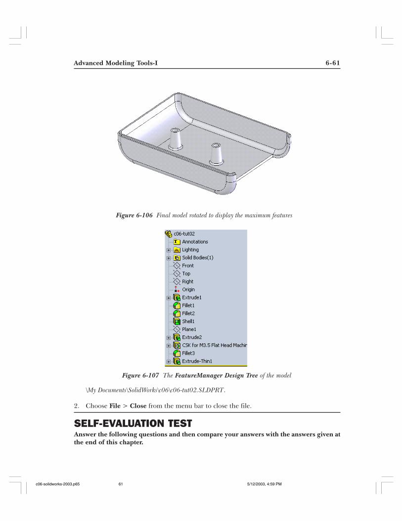
Advanced Modeling Tools-I 6-61
\My Documents\SolidWorks\c06\c06-tut02.SLDPRT.
2. Choose File > Close from the menu bar to close the file.
SELF-EVALUATION TESTAnswer the following questions and then compare your answers with the answers given atthe end of this chapter.
Figure 6-106 Final model rotated to display the maximum features
Figure 6-107 The FeatureManager Design Tree of the model
c06-solidworks-2003.p65 5/12/2003, 4:59 PM61
6-62 SolidWorks for Designers
1. Using the Hole PropertyManager you can create counterbore, countersink, and tappedholes. (T/F)
2. The hole features created using the Hole Wizard and the Hole PropertyManager arenot parametric. (T/F)
3. You cannot define a user-defined hole using the Hole Wizard. (T/F)
4. You cannot preselect the edges or faces for creating a fillet feature. (T/F)
5. In SolidWorks you can create a multi-thickness shell feature. (T/F)
6. The __________ check box is selected to create the shell feature on the outer side of themodel.
7. The __________ is created by specifying different radii along the length of selected edgeat specified intervals.
8. The names of the faces to be removed in the shell features are displayed in the __________display area.
9. If you want to specify different distances while creating the chamfer then clear the__________ check box.
10. The __________ check box is selected to apply the face fillet feature with continuouscurvature throughout the fillet feature.
REVIEW QUESTIONSAnswer the following questions:
1. The __________ option is used to add the standard holes to the model.
2. After specifying all the parameters to a hole feature using the Hole Definition dialogbox, the __________ dialog box is displayed to specify the placement of the hole feature.
3. The __________ radio button is selected to create a smooth transition by smoothly blendingthe points and vertices on which you have defined the radius on the selected edge.
4. The __________ tab available in the Hole Definition dialog box is used to define theparameters to add a standard drilled hole.
5. By default, the __________ radio button is selected in the Chamfer PropertyManager.
c06-solidworks-2003.p65 5/12/2003, 4:59 PM62
Advanced Modeling Tools-I 6-63
6. If you preselect the placement surface for creating a hole feature using the Hole Wizardthen the resultant placement sketch will be a
(a) 2D sketch (b) Planar sketch(c) Basier spline (d) 3D sketch
7. Using which options you do not use radius while creating a fillet feature?
(a) Face fillet with hold line (b) Constant radius fillet(c) Variable radius fillet (d) Full round fillet
8. Which radio button from the Variable Radius Parameters rollout is used to create smoothtransition while creating a variable radius fillet?
(a) Straight transition (b) Parametric transition(c) Smooth transition (d) Surface transition
9. If you do not select any face to be removed while creating a shell feature, then what willbe the resultant model?
(a) Remains complete solid model (b) Thin walled hollow model(c) Automatically removed one face (d) None of these
10. Which dialog box is displayed when you choose the Hole Wizard button from the Featurestoolbar?
(a) Hole (b) Hole Definition(c) Hole Wizard (d) Hole Parameters
EXERCISES
Exercise 1Create the model shown in Figure 6-108. The dimensions of the model are shown inFigure 6-109. (Expected time: 30 min)
c06-solidworks-2003.p65 5/12/2003, 4:59 PM63
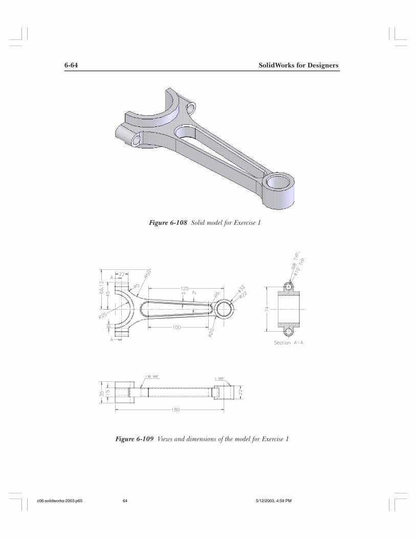
6-64 SolidWorks for Designers
Figure 6-108 Solid model for Exercise 1
Figure 6-109 Views and dimensions of the model for Exercise 1
c06-solidworks-2003.p65 5/12/2003, 4:59 PM64
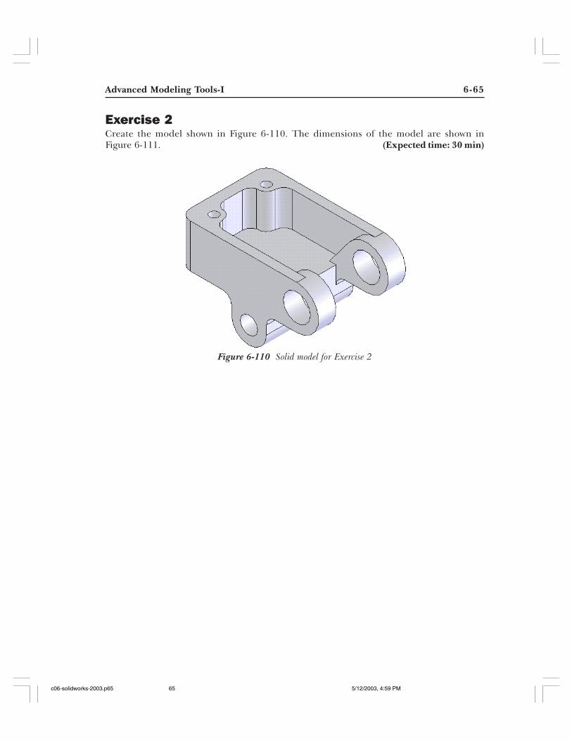
Advanced Modeling Tools-I 6-65
Figure 6-110 Solid model for Exercise 2
Exercise 2Create the model shown in Figure 6-110. The dimensions of the model are shown inFigure 6-111. (Expected time: 30 min)
c06-solidworks-2003.p65 5/12/2003, 4:59 PM65
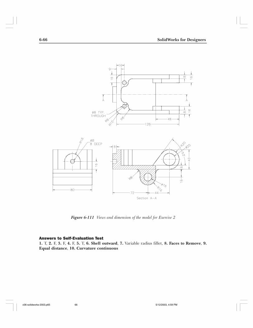
6-66 SolidWorks for Designers
Figure 6-111 Views and dimension of the model for Exercise 2
Answers to Self-Evaluation Test1. T, 2. F, 3. F, 4. F, 5. T, 6. Shell outward, 7. Variable radius fillet, 8. Faces to Remove, 9.Equal distance, 10. Curvature continuous
c06-solidworks-2003.p65 5/12/2003, 4:59 PM66