Embed Size (px)
Citation preview

Otasuke GP-EX!
6 - 1
Chapter 6 Alarm History Screen
Alarm History Screen
Chapter 6

Otasuke GP-EX!
6 - 2
Chapter 6 Alarm History Screen
6. 1 Alarm History Screen
Alarm History Screen ………………………………… 6-3
6. 2 Alarm History Display
Display Alarm History in List ………………………… 6-5
[Practice] Let’s Display Alarm History ……………… 6-7
6. 3 Data Read when Alarms Occur
Read Data when Alarms Occur ……………………… 6-15
[Practice] Let’s Read Data when Alarm Occur ……… 6-16
6. 4 Alarm Message Operation
[Practice] Let’s Edit Alarm Message ………………… 6-19
[Practice] Alarm History Switch ……………………… 6-20
6. 5 Sub Screen Display
Display Details/Countermeasures of Each Alarm … 6-23
[Practice] Let’s Display Details of Each Alarm Message …………………………………………… 6-25
6. 6 CF Card Save Settings
Save SRAM Data in CF Card………………………… 6-29
6. 7 Banner Message Display
Display Banner Message ……………………………… 6-35
[Practice] Let’s Display Banner Messages ………… 6-36
[Practice] Let’s Transfer Data to GP and Check Performance ………… ………………………………… 6-38
Chapter 6 Alarm History Screen

Otasuke GP-EX!
6 - 3
Chapter 6 Alarm History Screen
6. 1Alarm History
Screen

Otasuke GP-EX!
6 - 4
Chapter 6 Alarm History Screen
1 2
1)
Operates how to display alarm messages.
(→ See page 6-19.)3)
Displays an alarm history in a list.
(→ See page 6-5.)
Alarm Occurrence Switches
On the practice screen, if you touch a switch on the top right of the screen, [Alarm Occurrence Switches] will be displayed. You can operate alarm bits virtually.
The alarm history screen helps you to improve the line maintenance, the production efficiency, etc. by displaying alarm messages with their triggered and recovered times as a history. Also you can display the detail contents or countermeasures of alarms in a sub screen. Anyone can recover occurred abnormality easily using this feature.
2) Reads data when alarms occur.
(→ See page 6-15.)
Displays countermeasures by touching each message.
(→ See page 6-25.)
4)
3
4
One Point
5
Displays active alarms as banner messages.
(→ See page 6-35.)
5)
Alarm History Screen

Otasuke GP-EX!
6 - 5
Chapter 6 Alarm History Screen
Alarm History Display
6. 2

Otasuke GP-EX!
6 - 6
Chapter 6 Alarm History Screen
Alarm
Image of Alarm History Display
1) PLC → SRAM: Backs up an alarm history to the backup SRAM in the GP.
2) SRAM → Alarm: Displays data in the backup SRAM on a GP screen.
3) Print: Prints out alarm history data from the GP.
4) Save in Memory Card: Backs up an alarm history from the backup SRAM to a memory card.
Every time any of addresses registered in a PLC changes, a message is saved with the occurred time in the GP backup SRAM and displayed in an alarm list on the GP screen. Data in the backup SRAM can be printed out or saved in a CF card.
Printer
CF CardBackupSRAM
1
3
4
Inside of GPAbnormalityOccurred!
One Point
Data backed up from SRAM to a memory card is saved in CSV format. You can edit the data on your PC easily.
Memory Card
②
USB Memory
Display Alarm History in List
2

Otasuke GP-EX!
6 - 7
Chapter 6 Alarm History Screen
1) Register bit addresses and messages with [Bit Monitoring] in the Alarm settings.
2) Place an [Alarm] to display alarms and make settings.
3) Save the project file and transfer it to the GP.
Setup Procedures of Alarm History Display
The maximum number of alarms that can be stored in the backup SRAM is 768.
When the number of triggered alarms exceeds the specified number, the oldest alarm will be deleted.
If you keep saving a history for a long term, it is recommended to use a memory card. Memory Card
BackupSRAM
Note

Otasuke GP-EX!
6 - 8
Chapter 6 Alarm History Screen
(1) Select Alarm
Click the [Alarm] settings icon on the tool bar.
Let’s register alarm messages of each line and display a history.
[Setup Procedure]
1. Open the Alarm settings window. 2. Register monitor addresses and messages. 3. Select, place and set the Alarm on the base
screen “6”.
Open the base screen “6”.
(2) Common Settings
Block Settings: Set the display method of an alarm history and the number of records for Block 1 to 8. Here, check [History: Use] and set [Record] to “16” in [Block: Number 1] .
Backup History: Set whether to keep the history or not after turning on the power again. Here, check [Backup History] and [Hide Continuing Alarms].
1 21)
2)
Click the [Common] tab.
Let’s Display Alarm History
<Practice Screen> <Completed Screen>

Otasuke GP-EX!
6 - 9
Chapter 6 Alarm History Screen
One Point
Line A: Abnormal Speed Line A alarm history registered
in Block 1 is displayed on Base Screen 10.
B10 Line A
e.g.) Display messages by lines on three screens.
Block 3
Block 2
Block 1
BackupSRAM
Block
Dividing an alarm history storage area enables to display multiple alarms by types.
* You can categorize messages by occurrence places, persons in charge, levels of importance, etc.
Line A: Abnormal Electricity
Line A: Line Blockage
B20 Line B
B30 Line C
Line B alarm history registered in Block 2 is displayed on Base Screen 20.
Line C alarm history registered in Block 3 is displayed on Base Screen 30.
Line B: Abnormal Speed
Line B: Abnormal Electricity
Line B: Line Blockage
Line C: Abnormal Speed
Line C: Abnormal Electricity
Line C: Line Blockage

Otasuke GP-EX!
6 - 10
Chapter 6 Alarm History Screen
(3) Set Bit Monitoring of Block 1
Select an alarm monitoring address, either [Bit Monitoring] or [Word Monitoring].
Bit Monitoring: When a specified bit address turns on or off, a registered message will be displayed.
Word Monitoring: When a value of a specified word address is equal to an alarm value or out of the range, a registered message will be displayed.
Here, select [Bit Monitoring].
Make settings of [Bit Monitoring].
Bit Address: Register monitor bit addresses.
Trigger Condition: Set to trigger an alarm either when the monitor bit address turns on or when it turns off.
Message: Register alarm messages to display.
Level: Select an alarm level for each an alarm level from 0 to 7.
Sub Display Screen Number: Set the number of screen to display as a sub screen.
* If you do not set a sub display, set “0”.
Here, enter [Bit address], [Trigger Condition], [Message], [Level], and [Sub Display Screen Number] as registered in the above figure. This sample already has 12 alarm messages registered. Let’s register 13th alarm and later.
Select [blocks 1].
1
2
1)
2)

Otasuke GP-EX!
6 - 11
Chapter 6 Alarm History Screen
(4) Select/Place Alarm
1) Click the [Alarm] icon on the tool bar.
2) Drag the range to place the alarm.
1
2
(5) Basic Settings
1) Double-click the placed alarm.
2) Select [Show History].
3) Make settings as below. Display Block: Block 1Display Mode: HistoryDisplay Start Row: 1Display Rows: 10Display Row Spacing: 3
2
3
To edit addresses in the Alarm settings, you can use Cut, Copy, Paste, etc. by right-click.
One Point

Otasuke GP-EX!
6 - 12
Chapter 6 Alarm History Screen
Log: An alarm is displayed by the triggered time, acknowledged time, and recovered time separately in different rows.
It is useful in cases that the triggered and recovered times are on different dates.
History: A newly triggered alarm is displayed in a new row.
The time when the alarm is acknowledged or recovered is added onto the same row.
Active: Only active alarms are displayed.
The recovered alarm is cleared and no history remains.
One Point
* When you use multiple blocks, you can use different display modes by blocks.
For example, you can use the “Active” mode which does not leave histories for a line with low level of importance, the “Log” mode to leave histories for a line with high level of importance, etc.
Example of Display Mode (Active/History/Log)
e.g.)
e.g.)
e.g.)

Otasuke GP-EX!
6 - 13
Chapter 6 Alarm History Screen
Here on this tab, you can make each setting such as showing/hidingitems, Show Item Names,and Display Order.
Check from [Date] up to [Occurrences]. Set [Display Characters] as below.
Left Margin: 0Date: 6Trigger: 6Message: 19Acknowledged: 6Recovery: 6Occurrences:5
Check all of [Show Item Names] and register item names to display as above.
(6) Item Settings
2
11) Click and open the
[Extended] settings.
2)
In [Format], set [Date] to “mm/dd” and [Time] to “24:00”. 3)
3
4
4) In [Show-Item-Name Settings], select [Direct Text] and make settings as below.
Font Type: Standard Font Size: 8 x 16 PixelsDisplay Language: ASCII Text Attribute: ShadowDisplay Color: 7 Blink: NoneShadow Color: 1 Blink: NoneBackground Color: E3 Blink: None
(7) Color Settings
Set [Display Color], [Background Color], and [Blinks] as you like.
Set [Clear Color] as you like.

Otasuke GP-EX!
6 - 14
Chapter 6 Alarm History Screen
(8) Display Settings
1) Select “Standard Font” for [Font Type] and “8 x 16 Pixels” for [Size].
Select “Border with Horizontal Lines” for [Border].
Click [OK] to finish settings. 2)
1

Otasuke GP-EX!
6 - 15
Chapter 6 Alarm History Screen
6. 3Data Read when
Alarms Occur

Otasuke GP-EX!
6 - 16
Chapter 6 Alarm History Screen
When a bit address to be monitored turns on/off, or an alarm is written in a word address to be monitored, data will be read according to the states of the triggered, acknowledged or recovered alarms.
Analyzing data values shortens the time to find a cause of the triggered alarm.
When a bit address to be monitored turns on or off…
When an alarm is written in a word address to be
monitored…
Data will be displayed according to the triggered, acknowledged, or recovered time of the active alarm.
Date Time Error Press. Temp. Flow Rate2007/5/31 10:02:00 Heater Error 20 800 492007/5/31 10:03:01 A/ C Overheat 10 120 432007/5/31 10:12:18 Heater Error 10 80 222007/5/31 10:32:57 Freezer Fan Error 7 65 31
One Point
Alarm Interlocking LogYou can get an error message and device values from the device/PLC at the same time, which allows you to find a cause of the error quickly.Also, since it is possible to save logged data in CSV format, you can analyze data on your computer afterward.
Procedures of Setup
1) Register addresses to read data value when alarms occur in the alarm settings.
2) Make settings to display data by reading with the alarm parts.
Read Data when Alarms Occur
or

Otasuke GP-EX!
6 - 17
Chapter 6 Alarm History Screen
Let’s display the alarm detail, the triggered time, and the data
which causes an alarm when a bit address to be monitored is on!
[Setup Procedure]1. Open the Alarm settings window. 2. Set number of addresses to read data to and
addresses. 3. Set items of [Alarm].
(1) Select Alarm Settings
Click the [Alarm] settings icon on the tool bar.
(2) Set Block 1
Check [Read Data From Each Alarm].
Set [Number of Addresses] to “5”. Check [Use same address] for all of the addresses from Address 1 to Address 5.Doing so reads data using the same addresses when alarms occur, regardless of the messages.
1)
1
2)
2
3
3)
Let’s Read Data when Alarms Occur
4
Click the icon of [Address 1] to open the [Address] settings dialog box.
Select “Bit” for [Type] and set [Address] to “M115” and click [OK] to close the window.
In the same way, set addresses as below.
[Address 2] Type: Word Address: D300[Address 3] Type: Word Address: D301[Address 4] Type: Word Address: D302[Address 5] Type: Word Address: D303
4)

Otasuke GP-EX!
6 - 18
Chapter 6 Alarm History Screen
1
Check [Address] and set [Display Characters] to “6”.
Check from [Address 1] to [Address 5] and set the item names as follows.
Address 1: AutoAddress 2: Line AAddress 3: Line BAddress 4: Line CAddress 5: Line D
2
3
When you set [Address], a “separator” appears in the Display Order field. On the GP, you can display the items above the separator without scrolling.
Select the separator and move it under [Address 3].
Click!
2)
3)
(3) Item Settings
1) Open the base screen “6” and double-click the placed alarm. Select the [Item] tab.

Otasuke GP-EX!
6 - 19
Chapter 6 Alarm History Screen
6. 4Alarm Message
Operation

Otasuke GP-EX!
6 - 20
Chapter 6 Alarm History Screen
Select items of switches to place. Here, check the following items and set [Label] for each item.
<Item> <Label>Start StrtEnd EndAcknowledged AckAck All Ack AllMove Upward UpMove Downward DownClear ClrClear All Clr AllIn Reverse Order of Trigger Date Sort DateIn Order of Number of Occurrences Sort NumReverse Order Display RvrsScroll Right Value >>Scroll Left Value <<
Let’s place a switch to edit alarm messages!
[Setup Procedure]
1. Open the base screen “6”.
2. Make the Switch settings for the Alarm.
Switch Settings
Open the base screen “6”. Double-click the placed alarm. 1
2
1)
Click [Select Shape] and select a desired shape for switches to place. 2)
3) Click to finish settings. You can move the switches to where you want to place.
Let’s Edit Alarm Message

Otasuke GP-EX!
6 - 21
Chapter 6 Alarm History Screen
Types of Switches Description
Start
If you touch [Start], a cursor will appear to operate the history. When the Freeze Mode is set, it suspends the currently displayed alarms by touching [Start] twice and prohibits the screen display from refreshing even when an alarm occurs, is acknowledged, or is recovered. To cancel the Freeze Mode, touch [End]. When you cancel it, the stored alarms will be all refreshed and displayed at one time.
EndIf you touch [End], the cursor will disappear and the key operation will be terminated.
Acknowledge
Acknowledge Shows the acknowledged time in the selected message.
Acknowledge All Shows the acknowledged times in all of the displayed messages.
Move
Move Upward Moves the cursor one row up.
Move Downward Moves the cursor one row down.
Scroll Up Moves the cursor up by a given number of rows.
Scroll Down Moves the cursor down by a given number of rows.
Clear
Clear Erases the selected message.
Clear All Erases all the displayed messages.
Clear Recovery Alarm Erases the selected alarm, which has been recovered.
Clear All Recovery Alarms
Erases all the recovered alarms.
Clear Acknowledged Alarm
Erases the selected alarm which has been acknowledged.
Clear All Acknowledged Alarm
Erases all the acknowledged alarms.
Clear Individual Number of Occurrences
Clears the number of occurrences of the selected message.
Clear All Number of Occurrences
Clears all the numbers of occurrences of the displayed messages.
Clear Individual Accumulated Time
Clears the accumulate time of the selected message.
Clear All Accumulated Time
Clears all the accumulate times of the displayed messages.
Sort
In Reverse Order of Trigger Date
Displays alarm messages in order of latest occurrence.
In Number of Occurrences Order
Displays alarm messages in descending order of occurrence frequency.
In Descending Order of Accumulated Time
Displays alarm messages in descending order of accumulated time.
Level & In Reverse Order of Trigger Date
Displays alarm messages in descending order of level. If multiple messages with the same level exist, they will be displayed in order of latest occurrence.
Level & In Descending Order of Number of Occurrences
Displays alarm messages in descending order of level. If multiple messages with the same level exist, they will be displayed in descending order of occurrence frequency.
Alarm Registration Order
Displays alarm messages in order of registration.
Reverse Order Displays alarm messages in reverse order of the current sorting.
Sub Display Displays a sub screen of the selected message.
Alarm Number AcquisitionObtains the alarm message number (the row number registered in [Alarm]) of the message at the current cursor position.
Alarm History Switch
Alarm History Switch: Types and Actions

Otasuke GP-EX!
6 - 22
Chapter 6 Alarm History Screen
Shapes and colors of switches created in the [Switch] settings of [Alarm] are all fixed.
To set shapes and colors for switches individually, use the Switch parts instead. Set them with [Switch] → [Special Switch] → [Alarm History Switch].
One Point

Otasuke GP-EX!
6 - 23
Chapter 6 Alarm History Screen
6. 5Sub Screen
Display

Otasuke GP-EX!
6 - 24
Chapter 6 Alarm History Screen
To display details or countermeasures of each alarm message, use the “Sub Display” feature. Touching a displayed alarm message directly displays a sub screen.
Example of Sub Display
1) Touch a displayed alarm message directly.
2) A sub screen corresponding to the selected alarm message will appear.
1
2
No Need! No Need!No Need!
Using the Sub Display feature saves your time to look into manuals, go in and out of the factory site, or call technical staffs!
Display Details/Countermeasures of Each Alarm

Otasuke GP-EX!
6 - 25
Chapter 6 Alarm History Screen
1) Create a Sub Screen (Text) to be displayed.
2) Allocate Sub Display Screen Numbers to messages in the Alarm settings.
3) Open the Alarm dialog box and make the [Sub Display] settings.
Setup Procedures of Sub Screen Display
4) Save the project file and transfer it to the GP.
Otasuke GP-EX!
6 - 26
Chapter 6 Alarm History Screen
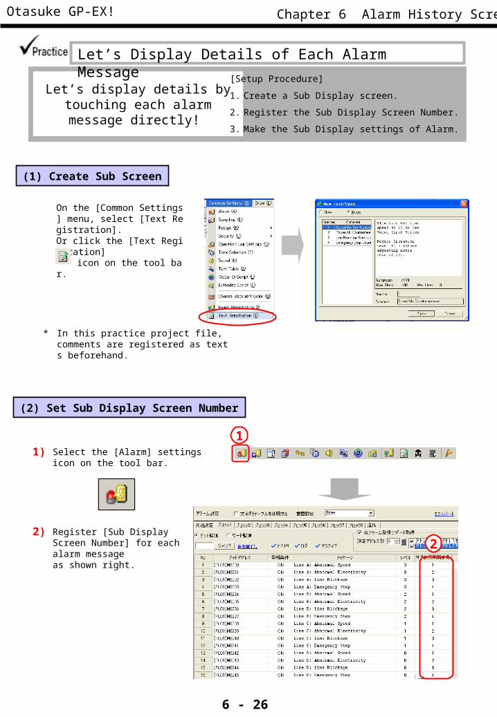
(1) Create Sub Screen
Let’s display details by touching each alarm message directly!
[Setup Procedure]
1. Create a Sub Display screen.
2. Register the Sub Display Screen Number.
3. Make the Sub Display settings of Alarm.
On the [Common Settings] menu, select [Text Registration]. Or click the [Text Registration] icon on the tool bar.
(2) Set Sub Display Screen Number
Select the [Alarm] settings icon on the tool bar.
1)1
2Register [Sub Display Screen Number] for each alarm message as shown right.
2)
* In this practice project file, comments are registered as texts beforehand.
Let’s Display Details of Each Alarm Message

Otasuke GP-EX!
6 - 27
Chapter 6 Alarm History Screen
(3) Sub Display Settings
1) Check [Enable the Sub Display]. Select “Show Text Window” for [Sub Display Type] and “Small” for [Window Size].
Open the base screen “6”. Double-click the placed alarm.
2) Adjust the window position on the base screen after clicking [OK].
The maximum number of characters that can be displayed in a row is as follows.
• Window Size Large: within 30• Window Size Small: within 20
Display position of a sub screen
If you set the Sub Display, a sub screen will be shown on the position setting mark located on the upper left of the Alarm part.You can change the display position of the sub screen by moving the position setting mark after selecting the Alarm part.
One Point
Top left corner of the sub screen

Otasuke GP-EX!
6 - 28
Chapter 6 Alarm History Screen
MEMO

Otasuke GP-EX!
6 - 29
Chapter 6 Alarm History Screen
CF Card Save Settings
6. 6

Otasuke GP-EX!
6 - 30
Chapter 6 Alarm History Screen
Backing up data in the SRAM to a CF card or a USB storage enables you to save large volumes of data for a long term. As the data are saved in the CSV format, it is possible to edit the data using spreadsheet software on your computer easily.
Memory Card
BackupSRAM
1) Open the System Settings window in the Work Space.
2) Click [Display Unit].
3) Select the [Mode] tab.
4) Check [Save Data] in the [Memory Card Settings] area and specify [Control Word Address].
(1) Select Memory Card Settings
4
1
23
Note
The way to save sampling data in a CF card is different from the way introduced above. ( See page 7-5)
Save SRAM Data in CF Card

Otasuke GP-EX!
6 - 31
Chapter 6 Alarm History Screen
To copy data from the SRAM to a CF card, write “Command” in Control Word Address. “Status” will be overwritten as a result.
“Control Word Address +1” will be the address to specify the file number in a CF card automatically.
Command/Status
File Number
e.g.) Control Word Address: D150
(2) Save Data in Memory Card
Save data of Alarm Block in the SRAM into a memory card as File Number 555.
D150 D151
1)
2)
0000h
555
3)
Save data of Alarm Block 1 in CF Card
D150
D151
0005h
555
D150
D151
0000h
555
SRAM
Data is copied at this moment.
← Write File Number “555”.
← Write Command “5h”.
← Status “0h” is overwritten when completed normally.
Data will be saved as a file “Z100555.CSV” in the Alarm folder in the CF card.
Control Word Address
+1 = D151
= D150
Spreadsheet Display Example
The contents in CSV files can be displayed on a GP screen. ( See page 6-33.)
One Point

Otasuke GP-EX!
6 - 32
Chapter 6 Alarm History Screen
Data Description
Command 0001h Filing Data
0002h GP-PRO/PB III (compatible)
0003h GP-PRO/PB III (compatible)
0004h GP-PRO/PB III (compatible)
0005h Data of Alarm History Block 1
0006h Data of Alarm History Block 2
0007h Data of Alarm History Block 3
0008h Data of Alarm History Block 4
0009h Data of Alarm History Block 5
000Ah Data of Alarm History Block 6
000Bh Data of Alarm History Block 7
000Ch Data of Alarm History Block 8
0020h GP-PRO/PB III (compatible)
0021h GP-PRO/PB III (compatible)
Status 0000h Completed Successfully
0100h Write Error
0200h CF card is not inserted or cannot access
0300h No data to be loaded
0400h File Number Error
(3) Command and Status
Folder Name Data to be saved File Name
∖ALARM Block 1 Data Z1*****.CSV
Block 2 Data Z2*****.CSV
Block 3 Data Z3*****.CSV
Block 4 Data Z4*****.CSV
Block 5 Data Z5*****.CSV
Block 6 Data Z6*****.CSV
Block 7 Data Z7*****.CSV
Block 7 Data Z8*****.CSV
(4) Alarm History Data Folder and File Name
Names of a folder and files in which alarm history data are written are listed below. These folder and files are created in a CF card.
In this practice screen, write “5h” and save data of Alarm History Block 1 in the SRAM into a CF card.
If “Command” is written in Control Word Address, “Status” will be reflected.
Other types of folders also can be created in a CF card. Please see GP-Pro EX Reference Manual for details.

Otasuke GP-EX!
6 - 33
Chapter 6 Alarm History Screen
(5) Save Sampling Data in CF Card
Set an address to save sampling data in a CF card in the setting window introduced below.
* See Chapter 7 for details of Sampling Data.
On the [Display/Save in CSV] tab of the sampling group, check [CSV Control Word Address] and set it.
Please be sure to use a different control word address from the one for “Save Data in CF Card” in the System settings. If you use the same address, the program may not perform normally.
Note
Command/Status
File Number
CSV Control Word Address
+1 = D161
= D160
Write “Command” in Control Word Address as “Save Data in CF Card”, which you have set in the system settings window. “Status” will be overwritten as a result.
“Control Word Address +1” will be the address to specify the file number in a CF card automatically.
e.g.) CSV Control Word Address: D160
* Procedures up to saving are the same as ones on page 6-29.
(6) Command and Status of Sampling Data
Data Description
Command 0001h Normal Save
0020h Auto-Save Start
0021h Auto-Save Completion
Status 0000h Completed Successfully
0100h Write Error
0200h No CF card inserted or inaccessible
0300h No data to be loaded
0400h File Number Error
2000h During Auto-Save
Folder Name File Name
∖SAMP01∼ ∖SAMP64
SA*****.CSV
(7) Sampling Data Folder and File Name
Data are stored in separate folders from SAMP1 to SAMP64 by sampling groups.
In this practice screen, write “20h” and save sampling data in the SRAM into a CF card automatically.

Otasuke GP-EX!
6 - 34
Chapter 6 Alarm History Screen
B102 Memory Card Saving Screen
B501 CSV Display Screen
One Point
Memory Card Saving Screen, CSV Display Screen
The memory card saving screen allows you to control the File Number and Command on the GP screen, and save data in the SRAM into a CF card. Also you can view contents in the files saved in a CF card on the CSV display screen.
* Open Memory Card Saving Screen
Touch the [Save in CF] switch on the base screen “6” or “7”, and the memory card saving screen will open.
Write “File No.” and “Command” with the word switch.
1)
Check Status. When completed normally, go to the CSV Display screen.
2)
Select a folder and then a file stored in a CF card on the File Manager display.
3)
Check data displayed on the CSV display.
4)
2
3
4
1
B6 Alarm History Screen B7 Data Sampling Screen
Using File Manager Display or CSV Display allows you to display and edit contents in a CSV file on the GP screen.

Otasuke GP-EX!
6 - 35
Chapter 6 Alarm History Screen
6. 7Banner
MessageDisplay
Otasuke GP-EX!
6 - 36
Chapter 6 Alarm History Screen
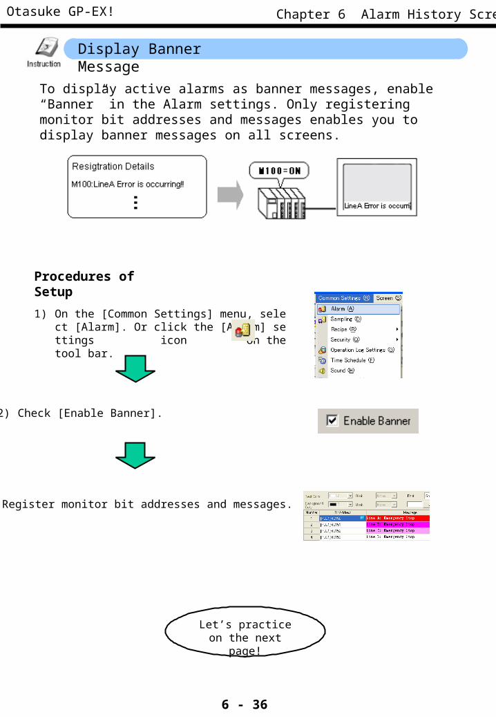
Display Banner Message
To display active alarms as banner messages, enable “Banner” in the Alarm settings. Only registering monitor bit addresses and messages enables you to display banner messages on all screens.
Procedures of Setup
1) On the [Common Settings] menu, select [Alarm]. Or click the [Alarm] settings icon on the tool bar.
2) Check [Enable Banner].
3) Register monitor bit addresses and messages.
Let’s practice on the next page!

Otasuke GP-EX!
6 - 37
Chapter 6 Alarm History Screen
Let’s Display Banner Messages
Let’s display banner messages of each line!
[Setup Procedure]1. Open the Alarm settings.2. Make the Alarm settings.
(1) Select Alarm Settings
1) On the [Common Settings] menu, select [Alarm]. Or click the [Alarm] settings icon on the tool bar.
(2) Register Monitor Bit Address and Messages
3) The [Banner] tab will be newly added.
1) On the [Common] tab, check [Enable Banner].
1
3
1
2) The window asking “The Banner Settings will be moved. Continue?” appears. Click [Yes].
2
<Practice Screen> <Completed Screen>

Otasuke GP-EX!
6 - 38
Chapter 6 Alarm History Screen
3) Set [Text Color], [Font], [Size], and [Background Color].
If you set [Blink], you can blink each color.
Set bit addresses to be monitored in [Bit Address] and messages to be displayed in [Message]. If [Print at Trigger Time] and [Print at Recovery Time] are set to ON and a printer is connected to the GP display, messages will be printed out at each status.
Here, set [Bit Address], [Message], [[Print at Trigger Time] and [Print at Recovery Time] as above.
4)
Click the [Save] icon on the tool bar.
(3) Save
Note
If any switches are behind the banner messages, touching the hidden part is unavailable. Please be sure to place parts, such as switches, not to hide behind the banner messages.
NG
3
4

Otasuke GP-EX!
6 - 39
Chapter 6 Alarm History Screen
Let’s Transfer Data to GP and Check Performance
1) Touch the alarm occurrence switch and check the alarm history. 2) Check performances of alarm message operation switches.
3) Touch the alarm message and check if the sub screen is displayed.
4) Touch the banner message switch and check if the banner messages is displayed.
1
2
3
4
<Completed Screen>

Otasuke GP-EX!
6 - 40
Chapter 6 Alarm History Screen
MEMO