Embed Size (px)
Citation preview
144
CHAPTER 6
ELASTIC-PLASTIC ANALYSIS OF HOMOGENEOUS
THICK-WALLED CIRCULAR CYLINDER UNDER
INTERNAL AND EXTERNAL PRESSURE WITH
STEADY STATE TEMPERATURE
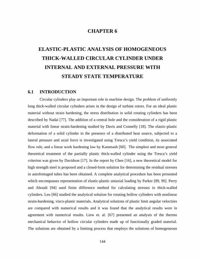
6.1 INTRODUCTION Circular cylinders play an important role in machine design. The problem of uniformly
long thick-walled circular cylinders arises in the design of turbine rotors. For an ideal plastic
material without strain hardening, the stress distribution in solid rotating cylinders has been
described by Nadai [77]. The addition of a central hole and the consideration of a rigid plastic
material with linear strain-hardening studied by Davis and Connelly [18]. The elastic-plastic
deformation of a solid cylinder in the presence of a distributed heat source, subjected to a
lateral pressure and axial force is investigated using Tresca’s yield condition, its associated
flow rule, and a linear work hardening law by Kammash [60]. The simplest and most general
theoretical treatment of the partially plastic thick-walled cylinder using the Tresca’s yield
criterion was given by Davidson [17]. In the report by Chen [16], a new theoretical model for
high strength steel is proposed and a closed-form solution for determining the residual stresses
in autofrettaged tubes has been obtained. A complete analytical procedure has been presented
which encompasses representation of elastic-plastic uniaxial loading by Parker [89, 90]. Perry
and Aboudi [94] used finite difference method for calculating stresses in thick-walled
cylinders. Leu [66] studied the analytical solution for rotating hollow cylinders with nonlinear
strain-hardening, visco-plastic materials. Analytical solutions of plastic limit angular velocities
are compared with numerical results and it was found that the analytical results were in
agreement with numerical results. Liew et. al. [67] presented an analysis of the thermo
mechanical behavior of hollow circular cylinders made up of functionally graded material.
The solutions are obtained by a limiting process that employs the solutions of homogeneous
145
hollow circular cylinders, with no recourse to the basic theory or the equations of
non-homogeneous thermo elasticity. Nie et. al. [81] presented a technique for functionally
graded linear elastic hollow cylinders and spheres to investigate stresses. The volume fractions
of two phases of a functionally graded material are assumed to vary only with the radius and
the effective material properties are estimated by using either the rule of mixtures or the Mori–
Tanaka scheme. A unified numerical method was developed by You and Zhang [144] for the
analysis of stresses in elastic–plastic rotating disks with arbitrary cross-sections of
continuously variable thickness and arbitrarily variable density made of non-linear strain-
hardening materials.The finite element model of the moderate rotation theory has been applied
on composite plates and shells by Palmerio et. al. [86]. These authors assumed
incompressibility of the material, yield conditions and power law relationship between stresses
and strains for the analysis. Infact, in most of the cases, it is not possible to find a solution in
closed form without these assumptions.
Transition theory [100, 111] does not require these assumptions and thus poses and
solves a more general problem from which cases pertaining to the above assumptions can be
worked out. It has been successfully applied to several problems, i.e. Sharma et.al. [118]
evaluated plastic stresses in thick-walled circular cylinder made of transversely isotropic
material while Sharma and Sahni [117] evaluated creep stresses in thick-walled rotating
cylinder under internal pressure made of transversely isotropic materials. Elastic-plastic
transition in a thin rotating disc with edge load has been studied by Gupta et. al. [42].
Elastic- plastic stresses in thin rotating disc with edge loading have been studied by Gupta et.
al. [43]. It is concluded that a rotating disc with edge load requires high increase in angular
speed to become fully plastic. Sharma [115] evaluated plastic stresses in thick-walled circular
cylinder made up of non-homogeneous materials while Gupta and Sharma [37] investigated
the elastic-plastic stresses in non-homogeneous circular cylinder under internal pressure with
temperature.
In this chapter, elastic-plastic stresses for a isotropic thick-walled circular cylinder with
internal and external pressure under steady state temperature have been obtained by using
Seth’s transition theory [100, 111]. The stresses as safety factors in cylinders with internal and
external pressure are in very high demand and are used in nuclear industry. Results obtained
have been discussed numerically and depicted graphically also.
146
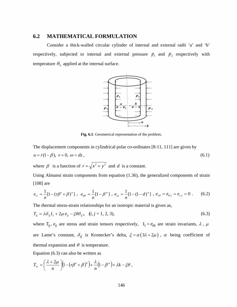
6.2 MATHEMATICAL FORMULATION Consider a thick-walled circular cylinder of internal and external radii ‘a’ and ‘b’
respectively, subjected to internal and external pressure 1p and 2p respectively with
temperature 0θ applied at the internal surface.
Fig. 6.1: Geometrical representation of the problem.
The displacement components in cylindrical polar co-ordinates [8-11, 111] are given by
dzvru ==−= ωβ ,0),1( , (6.1)
where β is a function of 22 yxr += and d is a constant.
Using Almansi strain components from equation (1.36), the generalized components of strain
[108] are
])(1[1 nrr r
ne ββ +′−= , ]1[1 n
ne βθθ −= ,
])1(1[1 n
zz dn
e −−= , 0=== zrzr eee θθ . (6.2)
The thermal stress-strain relationships for an isotropic material is given as,
ijijijij eIT ξθδµλδ −+= 21 , (i, j = 1, 2, 3), (6.3)
where ,ij ijT e are stress and strain tensors respectively, 1 kkI e= are strain invariants, λ , µ
are Lame’s constant, ijδ is Kronecker’s delta, ( )3 2ξ α λ µ= + , α being coefficient of
thermal expansion and θ is temperature.
Equation (6.3) can also be written as
( )( ) ( ) ξθλβλββµλ−+−++′−
+
= kn
rn
T nnrr 112 ,
147
( )( ) ( ) ξθλβµλββλθθ −+−
+
++′−
= k
nr
nT nn 121 ,
( )( ) ( ) ( ) ξθµλβλββλ−++−
++′−
= k
nr
nT nn
zz 211 ,
0=== θθ rzzr TTT , (6.4)
where ( )( )ndn
k −−= 111 .
Equations of equilibrium are all satisfied except,
0)( =
−
+r
TTT
drd rr
rrθθ . (6.5)
The temperature field satisfying Laplace equation 02 =∇ θ , with boundary conditions
0θθ = at r = a and 0=θ at r = b,
where 0θ is a constant, given by )/log()/log(
0 brba
θθ = (6.6)
6.3 IDENTIFICATION OF THE TRANSITION STATE
We know that as the point in the material has yielded, the material at the neighbouring
points is on their way to yield rather than they remain in their complete elastic state or fully
plastic state. Thus we can assume that there exists some state in between elastic and plastic
state which is called as transition state. So, at transition the differential system defining the
elastic state should attain some criticality.
The differential equation which comes out to be non–linear at transition state is
obtained by substituting equations (6.4) and (6.6) in equation (6.5), we get
( ) 02
1)1()1( 01 =+−−++
+++ −
nnn C
nCCPP
nCP
ddPPP
µβθξ
ββ , (6.7)
where Pr ββ =′ and )/(log
00 ba
θθ = .
The transitional or critical points of β in equation (6.7) are 1−→P and ±∞→P .
The boundary conditions are,
1pTrr −= at r = a, and 2pTrr −= at r = b . (6.8)
148
The resultant force normal to the plane z = constant is
122 ppdrrTb
azz −=∫π . (6.9)
6.4 SOLUTION THROUGH PRINCIPAL STRESS
The asymptotic solution at the transition points gives the solution for the transition
state of a particular configuration of the problem. The solution for the fully plastic state may
be obtained when the Poisson’s ratio is made to approach half. The material from elastic state
can go over into (i) plastic state, (ii) creep state or to any other state under external forces. All
these final states are reached through a transition state. As there are only principal stresses so
the transition can take place only through the principal stresses or through the principal stress
difference. It has been shown [8-11, 32, 44, 111-112, 115, 118, 128, 137] that the asymptotic
solution through the principal stress leads from elastic to plastic state at the transition point
±∞→P and thus, we define the transition function R as,
( )θαλ Ckn
TR rr 23 −+−=
= ( ) ( ) ( ){ }( ) ( )
−
−−−
−+−++−−
br
CC
nkCPC
nCnn log1
123111122
0θλαλβµ . (6.10)
Substituting the value of /dP dβ from equation (6.7) and taking the asymptotic value
±∞→P after taking the logarithmic differentiation of equation (6.10) w.r.t. ‘r’ which on
integrating yields CArR −= . (6.11)
where A is a constant of integration and µλ
µ2
2+
=C .
Using equation (6.11) in equation (6.10), we get
( )θα CBArT Crr 23 −−+= − , (6.12)
where kn
B λ= .
Using boundary conditions (6.8) in equation (6.12), we get
( ) ( )CC ba
ppCA −− −
−−−= 210 23αθ
, CAbpB −−−= 2 . (6.13)
Substituting the value of A and B in equation (6.12), we get
149
( ) ( ) ( ) ( )Cpbrba
ppCT CC
CCrr 2323
2210 −−−−
−−−−
= −−−− αθ
αθ . (6.14)
Using equation of equilibrium (6.5), we get
( ) ( ) ( )( ) ( )0 1 20 2
3 21 3 2 1 log .C C
C C
C p p rT C r b C pa b bθθ
αθαθ− −
− −
− − − = − − − − + − − (6.15)
The axial stress is obtained from equation (6.4) as
( )1 3 2 3 22 22 2 2zz rr zz
C C CT T T eC C Cθθ µ µ αθ− − − = + + − − − −
, (6.16)
where
[ ] ( )
( )
2 22 1
2 2
( ) (1 ) 3 22 (2 ) 2
3 22
b
rra
zz
p p r C CT T dr b aC C
eC b aC
θθ µαθπ
µ
− − − − + + − − − =− − −
∫. (6.17)
From equations (6.14) and (6.15), we get Tresca’s yield criterion as
( )CACrTT Crr 230 −−−=− − θαθθ (6.18)
Initial Yielding
It is found that the value of rrTT −θθ is maximum at ar = , which means yielding of the
cylinder will take place at the internal surface. Therefore, we have
( )0 3 2 (say) ,Crr r a
T T AC a C Yθθ αθ−=
− = − − − = (6.19)
where Y is yield stress.
The necessary effective pressure required for initial yielding is given by
2
31
2
21 1AA
AYppPi θ±=
−= , (6.20)
where CC
C
baCaA −−
−
−=2 ,
( )
−+
−−
−= −−
−
baC
baCaCA CC
C
log
23233 and
Y0
1αθ
θ = .
In the fully plastic state [8-11, 33, 42, 110-111, 115, 118, 121, 131] i.e. 0→C , equation (6.18)
become
150
,(say)log
3
log
3)(1
0021 Y
ba
ab
ppTTbrrr =
−
−−=−
=
αθαθθθ (6.21)
where 1Y is yield stress in fully plastic state.
The effective pressure required for fully plastic state is given from equation (6.21) as
1 2
1
logfp p bP
Y a− = =
. (6.22)
The radial, circumferential and axial stresses for fully plastic state are obtained by taking 0→C in equation (6.14) – (6.16) as
( )αθ
αθ3
log
log32
0
−−
−
= p
ab
brp
Trr ,
(6.23)
( )0
2 0
3 log 13 3 ,
log
rpbT p
ba
θθ
αθαθ αθ
− − = − − −
(6.24)
( )θθTTT rrzz +=21 . (6.25)
Now we introduce the following non-dimensional components as:
baR =0 ,
brR = ,
YTrr
r =σ , Y
Tθθθσ = ,
YTzz
z =σ , iiii
i PPY
ppP 21
21 −=−
=
ffff
f PPY
ppP 21
1
21 −=−
= .
The initial yielding in non-dimensional form from equation (6.20) is given as
5
61
5
1AA
APi θ±= , (6.26)
where CRCA
05 1−
= and ( )( )
−+
−−
−=00
6 log23
123
RC
RCCA C .
The transitional radial, circumferential and axial stresses in non-dimensional form from
equation (6.14) – (6.16) becomes,
151
( ) ( ) ( ) ( )( )
1 12
0 0
3 2 3 2 lo g1 ,
1 logi Crr
r iC
C P C RT R PY R R
θ θσ −− − −
= = − − −−
(6.27)
( ) ( )( ) ( ) ( )( )( ) i
CC
i PR
RCRCR
PCY
T2
0
1
0
1
loglog12311
123
−+−
−−−−
−−== − θθσ θθ
θ , (6.28)
( ) *1
0
1 log2 logz r zz
C ReC Rθσ σ σ θ− = + + − −
, (6.29)
where ( ) ( )
( )0
12 21 0
0*
20
(log / log )1 12 2 2
.1 12
rR
z
i
z
R RCb R dR RC
eR
Pθ
θσ σπ
− − − + + − − =
−
∫
The pressure required for fully plastic state 0→C in non-dimensional form from equation
(6.22) is given as
=
0
1logR
Pf . (6.30)
The radial, circumferential and axial stresses for fully plastic state in non-dimensional form
from equation (6.23) – (6.25) are given as
( ) ( )( ) 2
1 0
log,
logfrr
r f
P RT PY R
σ−
= = − (6.31)
( ) ( )( )( ) 2
1 0
1 log,
logf
f
P RT PY Rθθ
θσ− +
= = − (6.32)
( )θσσσ +== rzz
z YT
21
1
. (6.33)
6.5 CYLINDER UNDER EXTERNAL PRESSURE ONLY
The pressure required for fully plastic state 0→C in non-dimensional from equation
(6.30) is given as
==
01
2 1logRY
pPf , where fP is external pressure only. (6.34)
The radial, circumferential and axial stresses for fully plastic state in non-dimensional form
from equation (6.31) – (6.33) are given as
152
( ) ( )( )1 0
log,
logfrr
r
P RTY R
σ = = (6.35)
( ) ( )( )( )1 0
1 log,
logfP RT
Y Rθθ
θσ+
= = (6.36)
( )θσσσ +== rzz
z YT
21
1
. (6.37)
These equations are same as obtained by Sharma and Sahni [128].
6.6 NUMERICAL DISCUSSION AND CONCLUSION
As a numerical illustration, the values of pressure required for initial yielding and for
fully plastic state at different temperatures are taken as: p = 0, 25, 50, 75, 5.0,3.0,1.01 =θ .
The values of the compressibility factor is taken as C = 0.15, 0.35, 0.5.
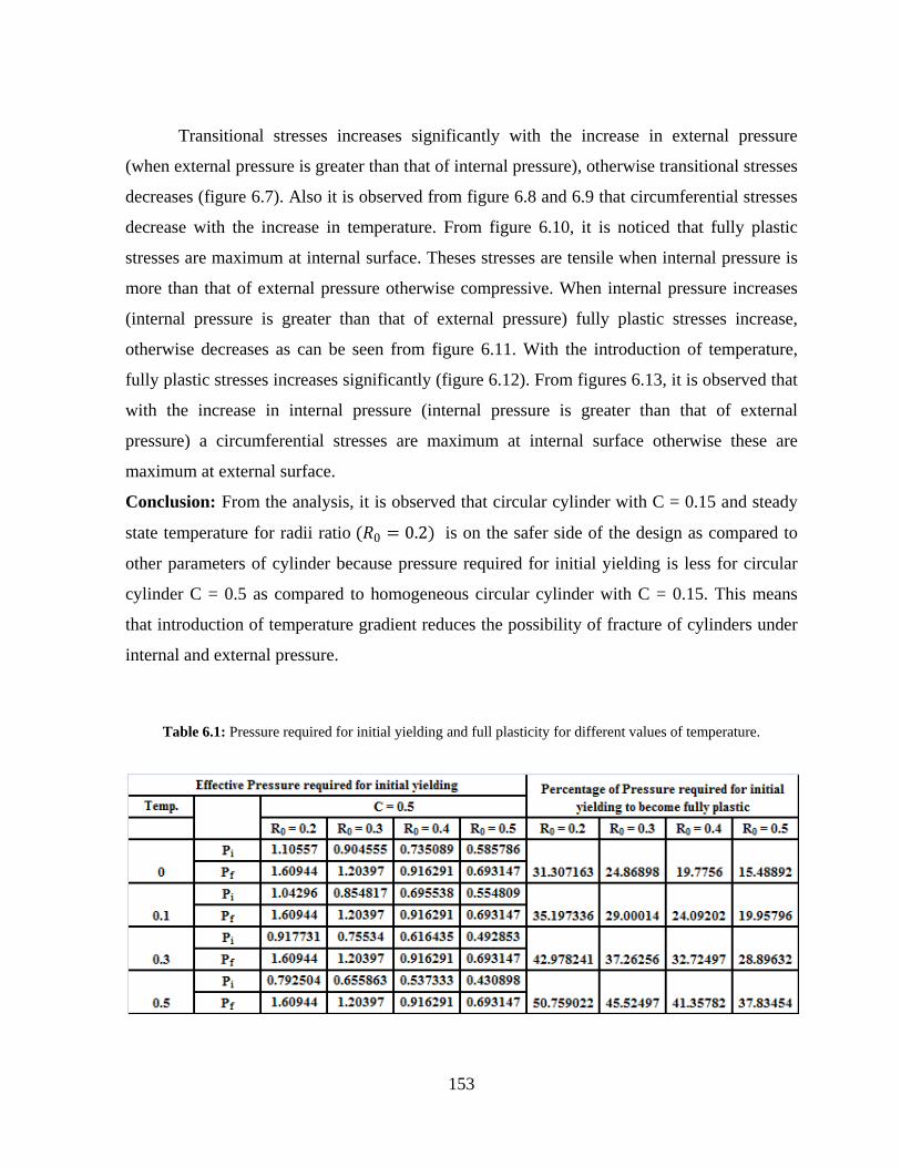
From table 6.1, it is observed that percentage increase in effective pressure required for
initial yielding to become fully plastic increases with the increase in temperature significantly.
Also, it is clear from table 6.1 that percentage increase in effective pressure required for initial
yielding to become fully plastic is high for circular cylinder with radii ratio 0.2 as compared to
cylinder with other radii ratios.
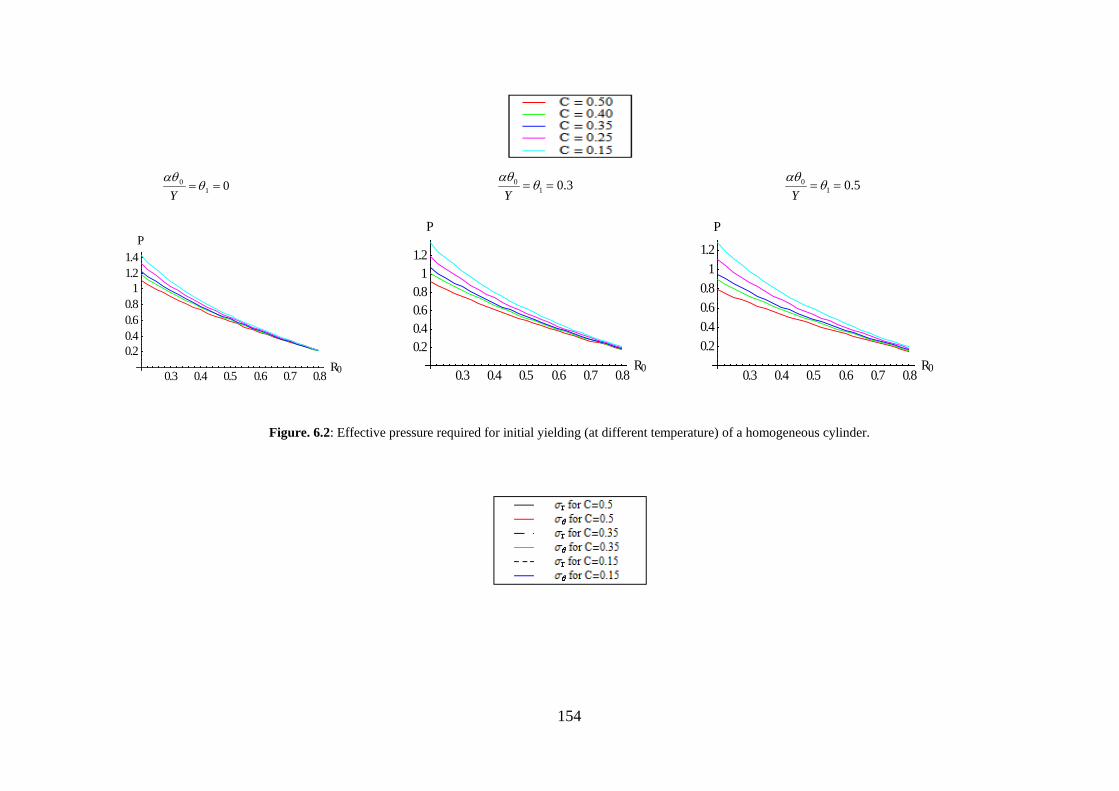
It is observed from figure 6.2 that without temperature, effective pressure required for
initial yielding maximum at internal surface. It is also noticed that pressure required for initial
yielding is less for circular cylinder with C = 0.5 as compared to homogeneous circular
cylinder C = 0.15. With the introduction of temperature, effective pressure required for initial
yielding decreases significantly.
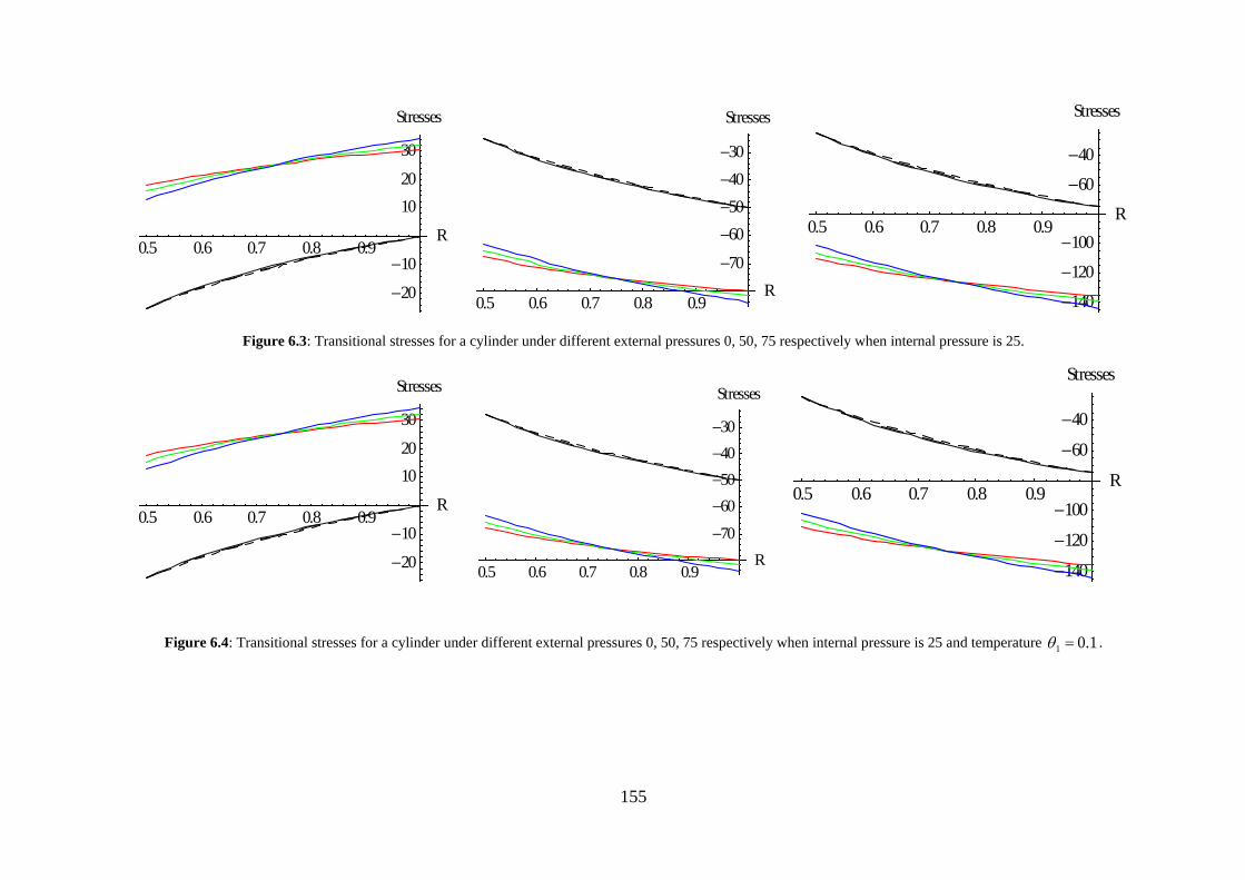
From figure 6.3, it is observed that cylinder whose internal pressure is fixed (say, 25)
transitional stresses are maximum at internal surface. When internal pressure is more than that
of external pressure, these stresses are compressible, otherwise tensile. It is clear from figure
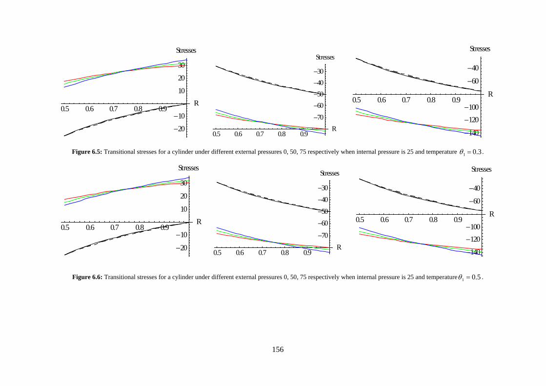
6.4 that with the introduction of temperature, circumferential stresses increases significantly
which further increases with the increase in temperature, as can be seen from figures 6.5 and
6.6. Also, it is observed that circular cylinder with C = 0.5 has less circumferential stress as
compared to circular cylinder C = 0.15.
153
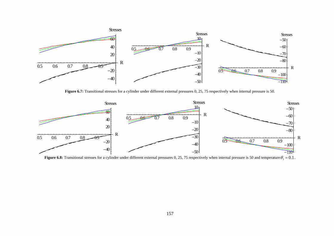
Transitional stresses increases significantly with the increase in external pressure
(when external pressure is greater than that of internal pressure), otherwise transitional stresses
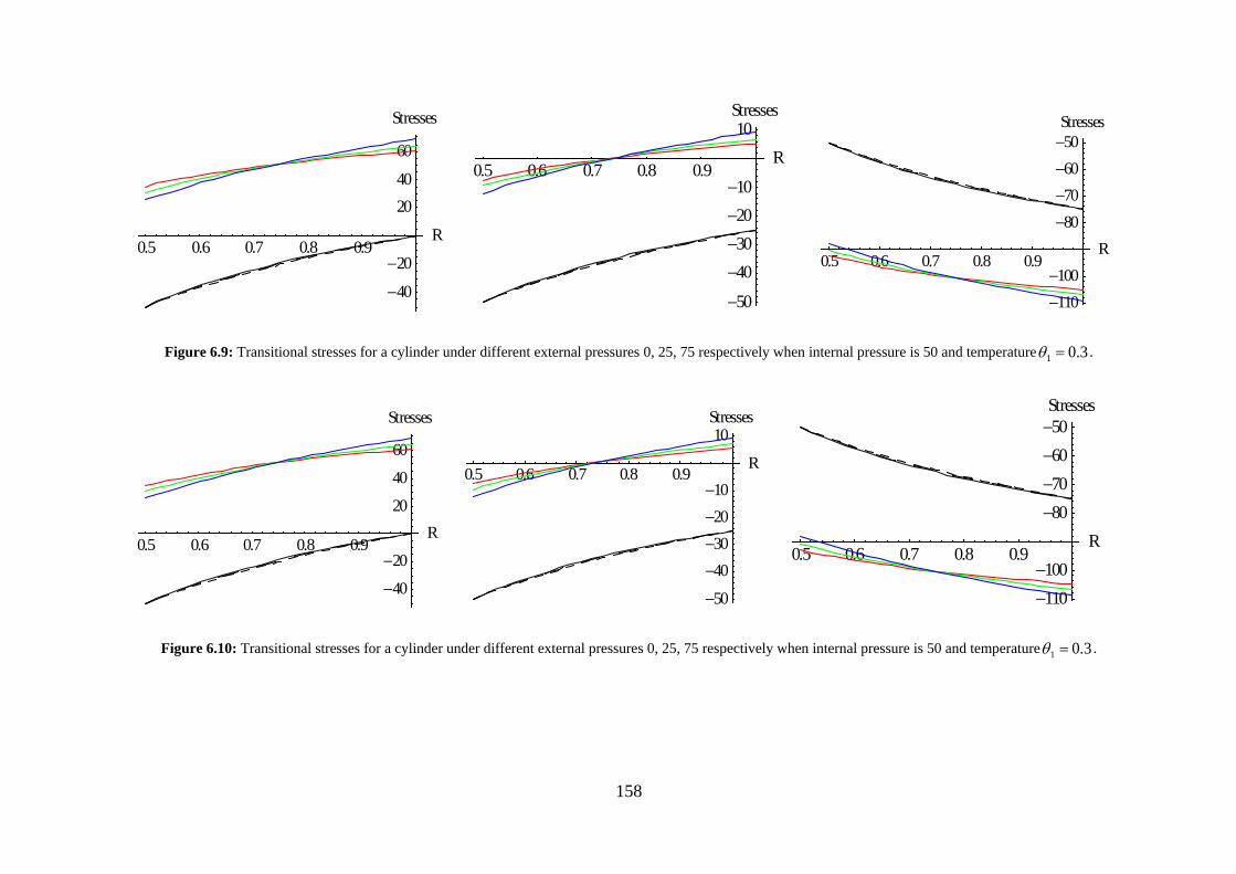
decreases (figure 6.7). Also it is observed from figure 6.8 and 6.9 that circumferential stresses
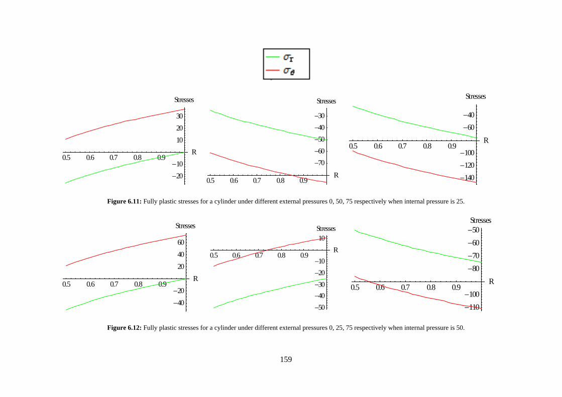
decrease with the increase in temperature. From figure 6.10, it is noticed that fully plastic
stresses are maximum at internal surface. Theses stresses are tensile when internal pressure is
more than that of external pressure otherwise compressive. When internal pressure increases
(internal pressure is greater than that of external pressure) fully plastic stresses increase,
otherwise decreases as can be seen from figure 6.11. With the introduction of temperature,
fully plastic stresses increases significantly (figure 6.12). From figures 6.13, it is observed that
with the increase in internal pressure (internal pressure is greater than that of external
pressure) a circumferential stresses are maximum at internal surface otherwise these are
maximum at external surface.
Conclusion: From the analysis, it is observed that circular cylinder with C = 0.15 and steady
state temperature for radii ratio (𝑅𝑅0 = 0.2) is on the safer side of the design as compared to
other parameters of cylinder because pressure required for initial yielding is less for circular
cylinder C = 0.5 as compared to homogeneous circular cylinder with C = 0.15. This means
that introduction of temperature gradient reduces the possibility of fracture of cylinders under
internal and external pressure.
Table 6.1: Pressure required for initial yielding and full plasticity for different values of temperature.
154
010 == θ
αθY
3.010 == θαθ
Y 5.01
0 == θαθY
Figure. 6.2: Effective pressure required for initial yielding (at different temperature) of a homogeneous cylinder.
0.3 0.4 0.5 0.6 0.7 0.8R0
0.20.40.60.8
11.21.4
P
0.3 0.4 0.5 0.6 0.7 0.8R0
0.20.40.60.8
11.2
P
0.3 0.4 0.5 0.6 0.7 0.8R0
0.20.40.60.8
11.2
P
155
Figure 6.3: Transitional stresses for a cylinder under different external pressures 0, 50, 75 respectively when internal pressure is 25.
Figure 6.4: Transitional stresses for a cylinder under different external pressures 0, 50, 75 respectively when internal pressure is 25 and temperature 1.01 =θ .
0.5 0.6 0.7 0.8 0.9R
20
10
1020
30
Stresses
0.5 0.6 0.7 0.8 0.9R
70
60504030
Stresses
0.5 0.6 0.7 0.8 0.9R
140
120
100
60
40
Stresses
0.5 0.6 0.7 0.8 0.9R
20
10
1020
30
Stresses
0.5 0.6 0.7 0.8 0.9R
70
60504030
Stresses
0.5 0.6 0.7 0.8 0.9R
140
120
100
60
40
Stresses
156
Figure 6.5: Transitional stresses for a cylinder under different external pressures 0, 50, 75 respectively when internal pressure is 25 and temperature
3.01 =θ .
Figure 6.6: Transitional stresses for a cylinder under different external pressures 0, 50, 75 respectively when internal pressure is 25 and temperature 5.01 =θ .
0.5 0.6 0.7 0.8 0.9R
20
10
10
20
30
Stresses
0.5 0.6 0.7 0.8 0.9R
70
60504030
Stresses
0.5 0.6 0.7 0.8 0.9R
140
120100
60
40
Stresses
0.5 0.6 0.7 0.8 0.9R
20
10
10
20
30
Stresses
0.5 0.6 0.7 0.8 0.9R
70
60504030
Stresses
0.5 0.6 0.7 0.8 0.9R
140
120100
60
40
Stresses
157
Figure 6.7: Transitional stresses for a cylinder under different external pressures 0, 25, 75 respectively when internal pressure is 50.
Figure 6.8: Transitional stresses for a cylinder under different external pressures 0, 25, 75 respectively when internal pressure is 50 and temperature 1.01 =θ .
0.5 0.6 0.7 0.8 0.9R
40
20
2040
60
Stresses
0.5 0.6 0.7 0.8 0.9R
50
40302010
10Stresses
0.5 0.6 0.7 0.8 0.9R
110100
80706050Stresses
0.5 0.6 0.7 0.8 0.9R
40
20
2040
60
Stresses
0.5 0.6 0.7 0.8 0.9R
50
40302010
10Stresses
0.5 0.6 0.7 0.8 0.9R
110100
80706050Stresses
158
Figure 6.9: Transitional stresses for a cylinder under different external pressures 0, 25, 75 respectively when internal pressure is 50 and temperature 3.01 =θ .
Figure 6.10: Transitional stresses for a cylinder under different external pressures 0, 25, 75 respectively when internal pressure is 50 and temperature 3.01 =θ .
0.5 0.6 0.7 0.8 0.9R
40
20
2040
60
Stresses
0.5 0.6 0.7 0.8 0.9R
50
40302010
10Stresses
0.5 0.6 0.7 0.8 0.9R
110100
80706050Stresses
0.5 0.6 0.7 0.8 0.9R
40
20
20
40
60
Stresses
0.5 0.6 0.7 0.8 0.9R
50
40302010
10Stresses
0.5 0.6 0.7 0.8 0.9R
110100
80706050Stresses
159
Figure 6.11: Fully plastic stresses for a cylinder under different external pressures 0, 50, 75 respectively when internal pressure is 25.
Figure 6.12: Fully plastic stresses for a cylinder under different external pressures 0, 25, 75 respectively when internal pressure is 50.
0.5 0.6 0.7 0.8 0.9R
2010
102030
Stresses
0.5 0.6 0.7 0.8 0.9R
7060504030
Stresses
0.5 0.6 0.7 0.8 0.9R
140120100
6040
Stresses
0.5 0.6 0.7 0.8 0.9R
4020
204060
Stresses
0.5 0.6 0.7 0.8 0.9R
5040302010
10Stresses
0.5 0.6 0.7 0.8 0.9R
110100
80706050Stresses