Embed Size (px)
Citation preview
107
CHAPTER 6
MICROSTRIP RECTANGULAR PATCH ARRAY WITH
FINITE GROUND PLANE EFFECTS
6.1 INTRODUCTION
The finite ground plane effects of microstrip antennas are one of the
issues for the wireless mobile communication applications given by Huang
(1983). To achieve exactly the specified beamwidth and front-to-back ratio,
especially for single element antennas or moderate size arrays, it is a difficult
task for the antenna designer with low cost, from Gonca Cakir and Levent
Sevgi (2005). It is very difficult to achieve the more accurate, efficient, and
flexible computation methods including the finite ground plane diffraction.
The spectral domain method of moment, from Ramesh and Yip (2003),
formulations based on the Green’s functions of an infinite grounded dielectric
slab yield, in most cases, accurate results for input impedances and resonant
frequencies. However, they will not allow us to predict the far field radiation
pattern correctly if the microstrip structure is finite. The simulation package,
IE3D (2003), uses the Methods of Moment (MOM) technique to evaluate the
finite ground plane effects. In this chapter, the various microstrip arrays are
designed with finite ground plane effects and compared with the infinite
counterpart.
From Lolit Kumar Singh et al (2012), the conventional microstrip
antennas assume infinitely large ground plane dimensions and thus they are
large in size. The size of ground plane is the limitation of antenna
108
characteristics, like distortion of radiation patterns, reduction of gain and
compactness.
Erik Lier and Kurt R. Jakobsen (1983) analyzed the rectangular
microstrip patch antenna extensively with regard to variation in its input
impedance and resonant frequency, both for infinite and finite ground plane
dimensions. Bhattacharyya A.K. (1990) reported an analytical technique for
the finite ground plane effect on radiation characteristics of a microstrip
antenna. The simulation results show that the gain of a circular patch antenna
varies with the ground plane size; also it is observed that the maximum gain is
achieved when the radius of the ground plane is 0.6 0. It was also found that
the input impedance changes widely with the ground plane dimension and
decreases with increase in the ground plane radius. The induced current on the
ground plane, derived therein, is an approximate one and does not include the
edge effects. Bhattacharyya A.K. (1991) reported the effects of ground plane
truncation on the impedance of a patch antenna. The input impedance was
found to vary widely with the ground plane dimensions, especially for
electrically thick substrates. In this chapter, the effect of finite ground plane
has considered for the linear and circular arrays with eight elements.
6.2 EM OPTIMIZATION WITH FINITE GROUND PLANES
In IE3D, on MGRID, structures are not described as parameterized
objects. All structures are described by polygons and polygons are described
by vertices. To change the shape of a structure, we need to change the
locations of vertices. It is necessary to identify which vertices to be adjusted
to change the values L and D. IE3DLIBRARY has complete parameterized
structure objects with equation-based dimensions. It is extremely flexible in
optimizing structures. Using this approach, a single patch has been designed
109
and further the same is used to design the microstrip array of various
configurations.
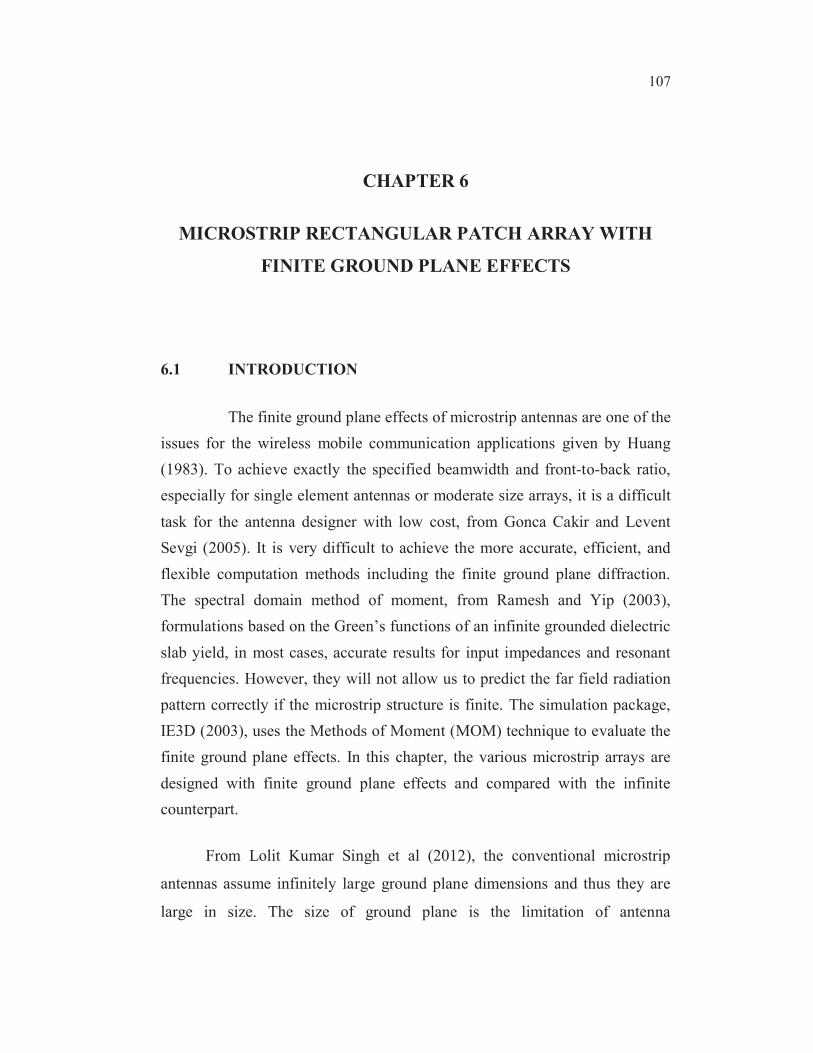
Figure 6.1 Plot of reflection coefficient without optimization
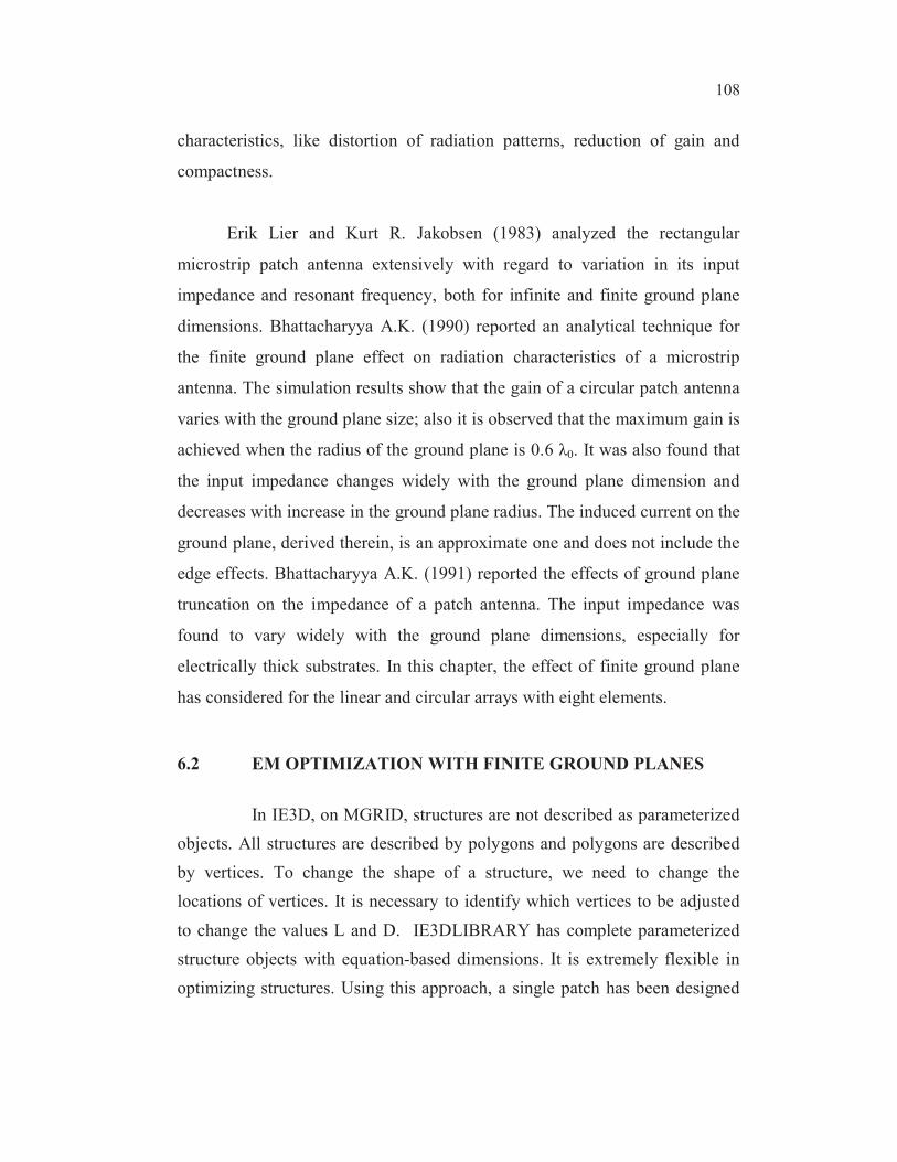
Figure 6.2 Plot of reflection coefficient of single patch with optimization
Figures 6.1 and 6.2, shows the reflection coefficient (S11) plot of
single patch microstrip antenna without and with optimization respectively. It
was observed that the reflection coefficient (S11) of - 47 dB has been achieved at
2.4 GHz by optimized patch antenna which can be used for WiMAX applications.
110
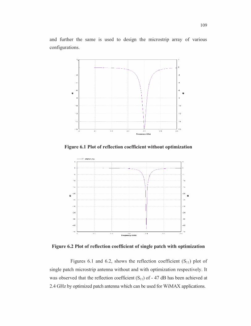
6.2.1 Optimization of Single Patch
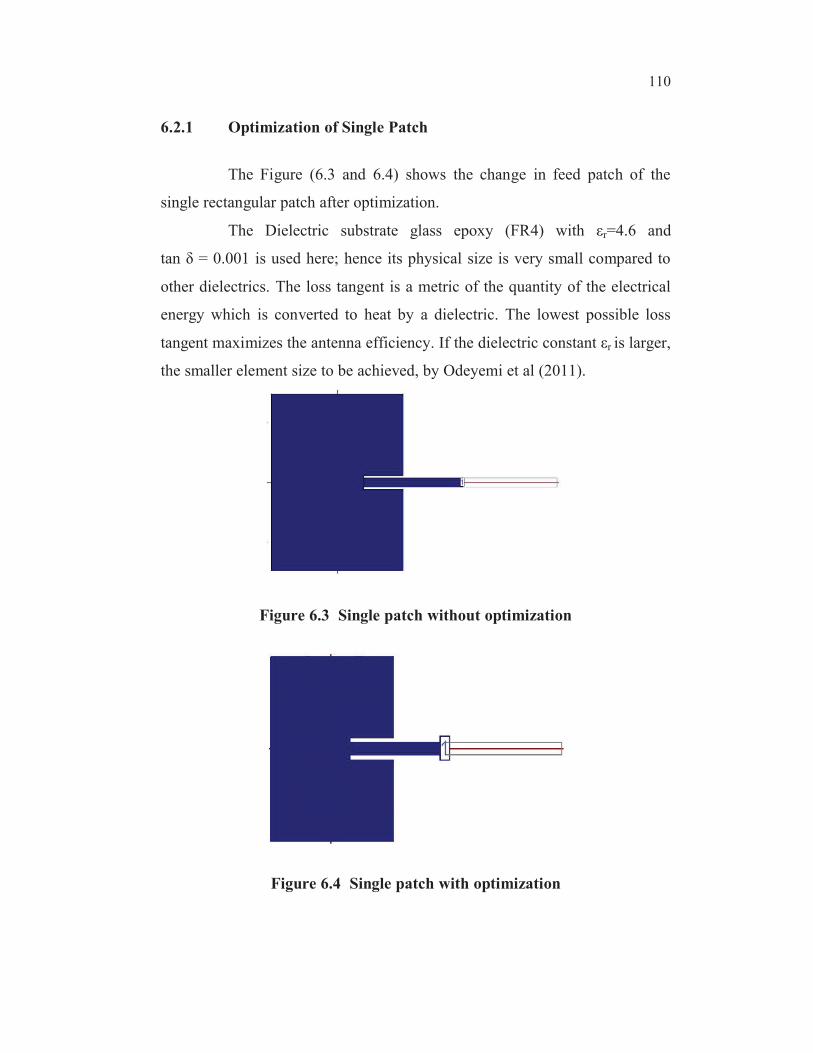
The Figure (6.3 and 6.4) shows the change in feed patch of the
single rectangular patch after optimization.
The Dielectric substrate glass epoxy (FR4) with r=4.6 and
tan = 0.001 is used here; hence its physical size is very small compared to
other dielectrics. The loss tangent is a metric of the quantity of the electrical
energy which is converted to heat by a dielectric. The lowest possible loss
tangent maximizes the antenna efficiency. If the dielectric constant r is larger,
the smaller element size to be achieved, by Odeyemi et al (2011).
Figure 6.3 Single patch without optimization
Figure 6.4 Single patch with optimization
111
The variable chosen here for optimization are length of the patch
and the depth of the inset feed given to the patch, from Jagdish (2010). The
corresponding vertices are selected and declared as variables for optimization
in ‘Optimization variable definition dialog’. The value of length is varied
from -100mils to 100mils from its default value. The value of inset depth is
varied from -150mils to 150mils from its default value. The optimization set
up is simulated for the resonant frequency 2.4 GHz with optimization goals as
real and imaginary part of s-parameter.
6.3 ARRAY CONFIGURATIONS AND ITS SIMULATIONS
USING IE3D
The microstrip linear, planar and circular microstrip arrays with and
without finite ground plane effects are simulated and the results were
compared at 2.4 GHz frequency.
6.3.1 Linear Array
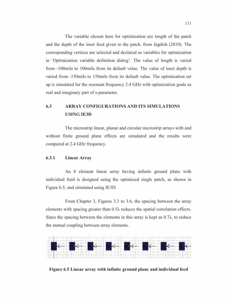
An 8 element linear array having infinite ground plane with
individual feed is designed using the optimized single patch, as shown in
Figure 6.5, and simulated using IE3D.
From Chapter 3, Figures 3.3 to 3.6, the spacing between the array
elements with spacing greater than 0.5 reduces the spatial correlation effects.
Since the spacing between the elements in this array is kept as 0.7 , to reduce
the mutual coupling between array elements.
Figure 6.5 Linear array with infinite ground plane and individual feed
112
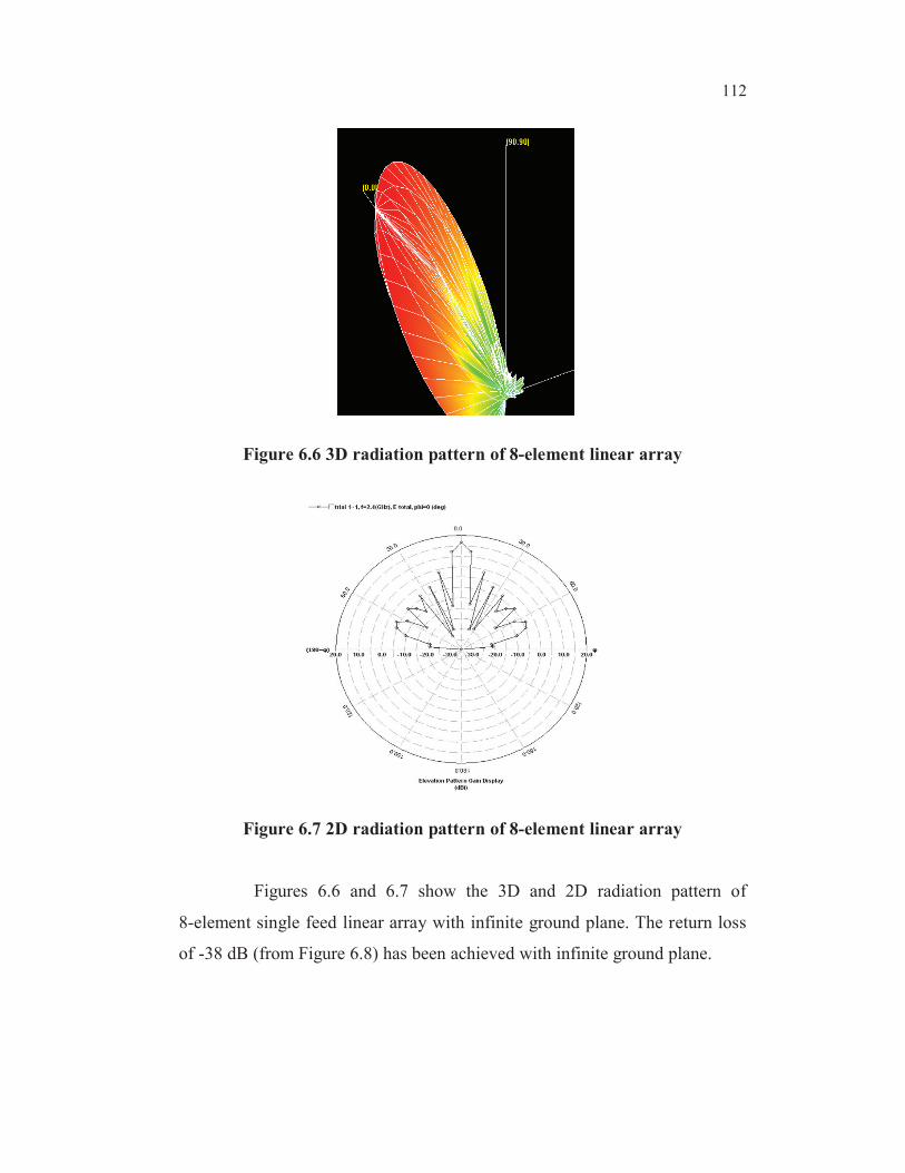
Figure 6.6 3D radiation pattern of 8-element linear array
Figure 6.7 2D radiation pattern of 8-element linear array
Figures 6.6 and 6.7 show the 3D and 2D radiation pattern of
8-element single feed linear array with infinite ground plane. The return loss
of -38 dB (from Figure 6.8) has been achieved with infinite ground plane.
113
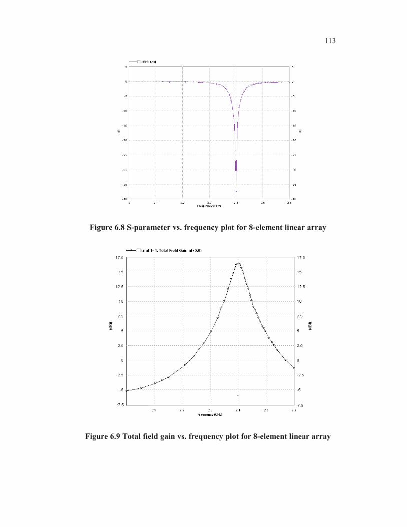
Figure 6.8 S-parameter vs. frequency plot for 8-element linear array
Figure 6.9 Total field gain vs. frequency plot for 8-element linear array
114
Figure 6.9 provides the variation of the gain (dBi) with respect to
frequency (GHz) for the 8 element linear array. The total field gain of around
16.5 dBi is obtained at the design frequency 2.4 GHz.
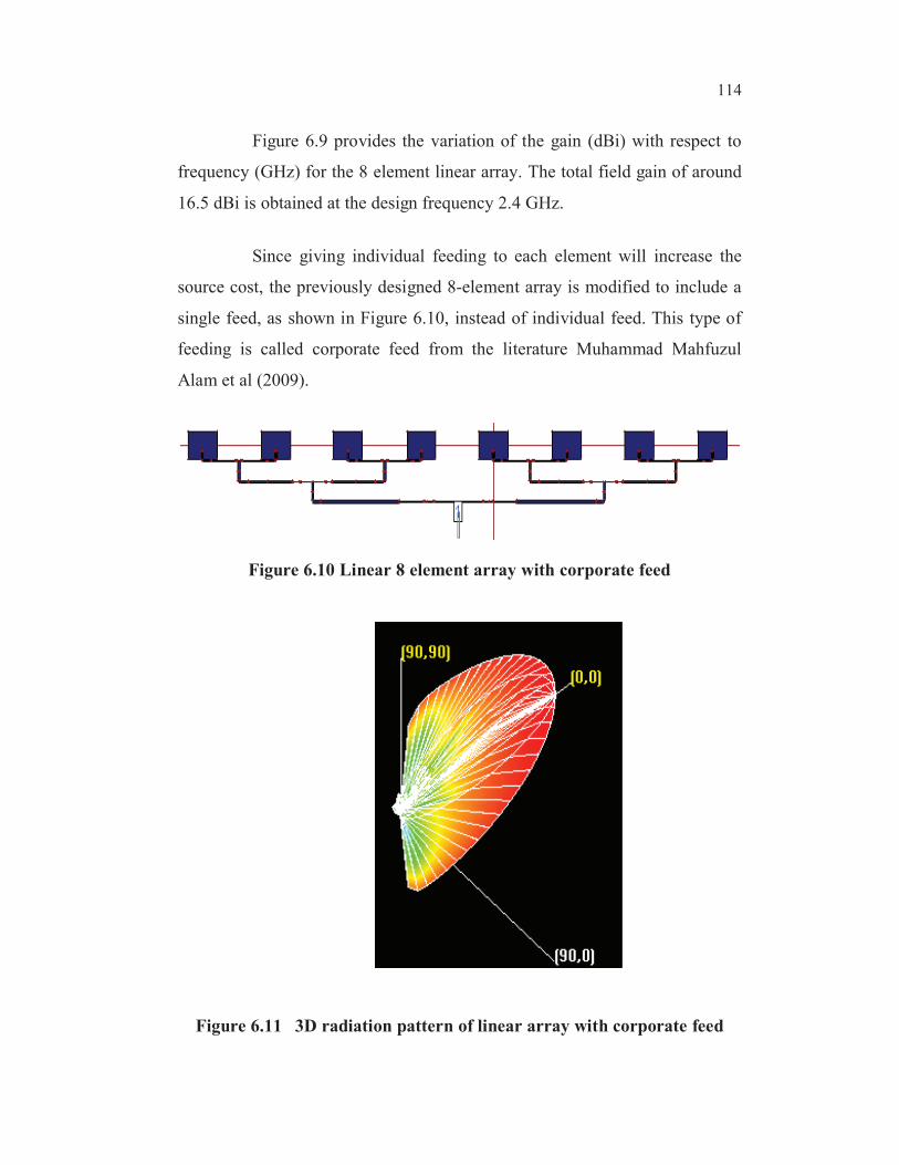
Since giving individual feeding to each element will increase the
source cost, the previously designed 8-element array is modified to include a
single feed, as shown in Figure 6.10, instead of individual feed. This type of
feeding is called corporate feed from the literature Muhammad Mahfuzul
Alam et al (2009).
Figure 6.10 Linear 8 element array with corporate feed
Figure 6.11 3D radiation pattern of linear array with corporate feed
115
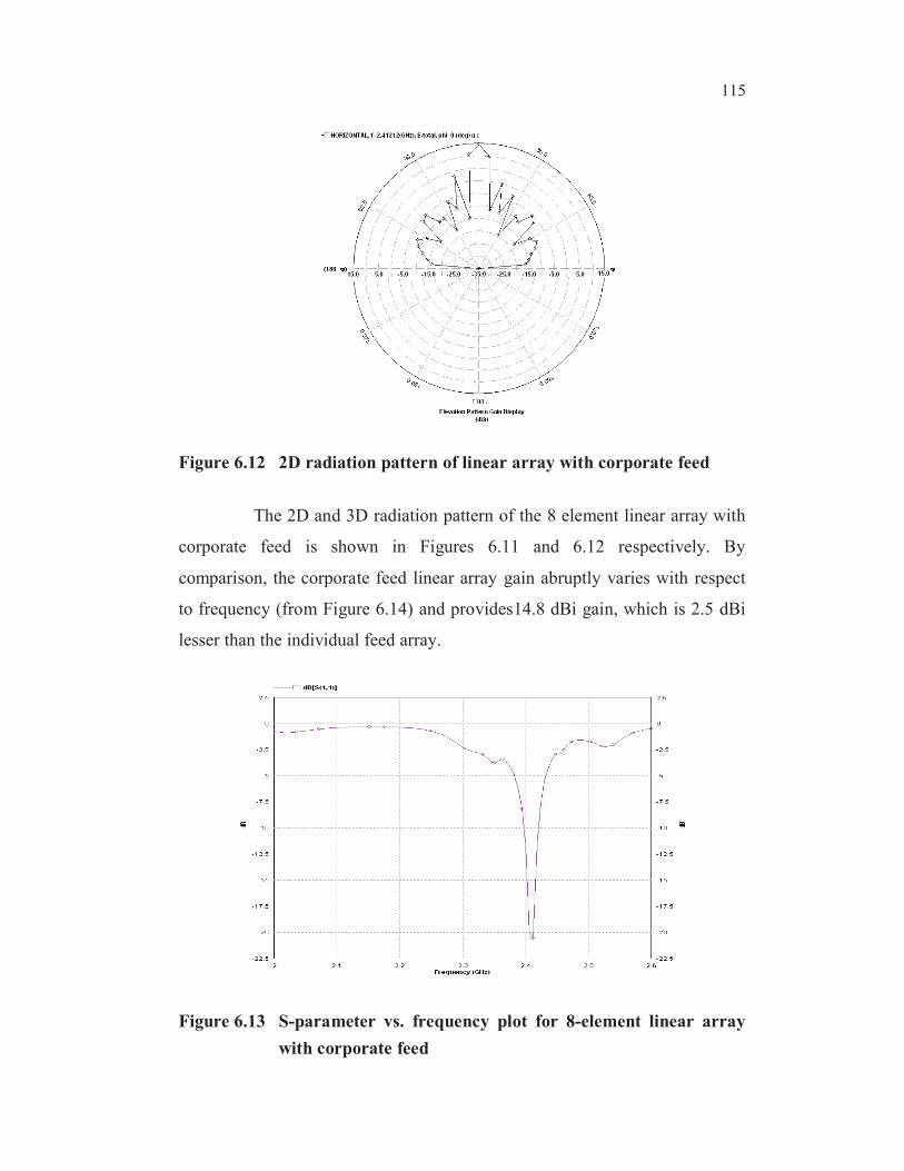
Figure 6.12 2D radiation pattern of linear array with corporate feed
The 2D and 3D radiation pattern of the 8 element linear array with
corporate feed is shown in Figures 6.11 and 6.12 respectively. By
comparison, the corporate feed linear array gain abruptly varies with respect
to frequency (from Figure 6.14) and provides14.8 dBi gain, which is 2.5 dBi
lesser than the individual feed array.
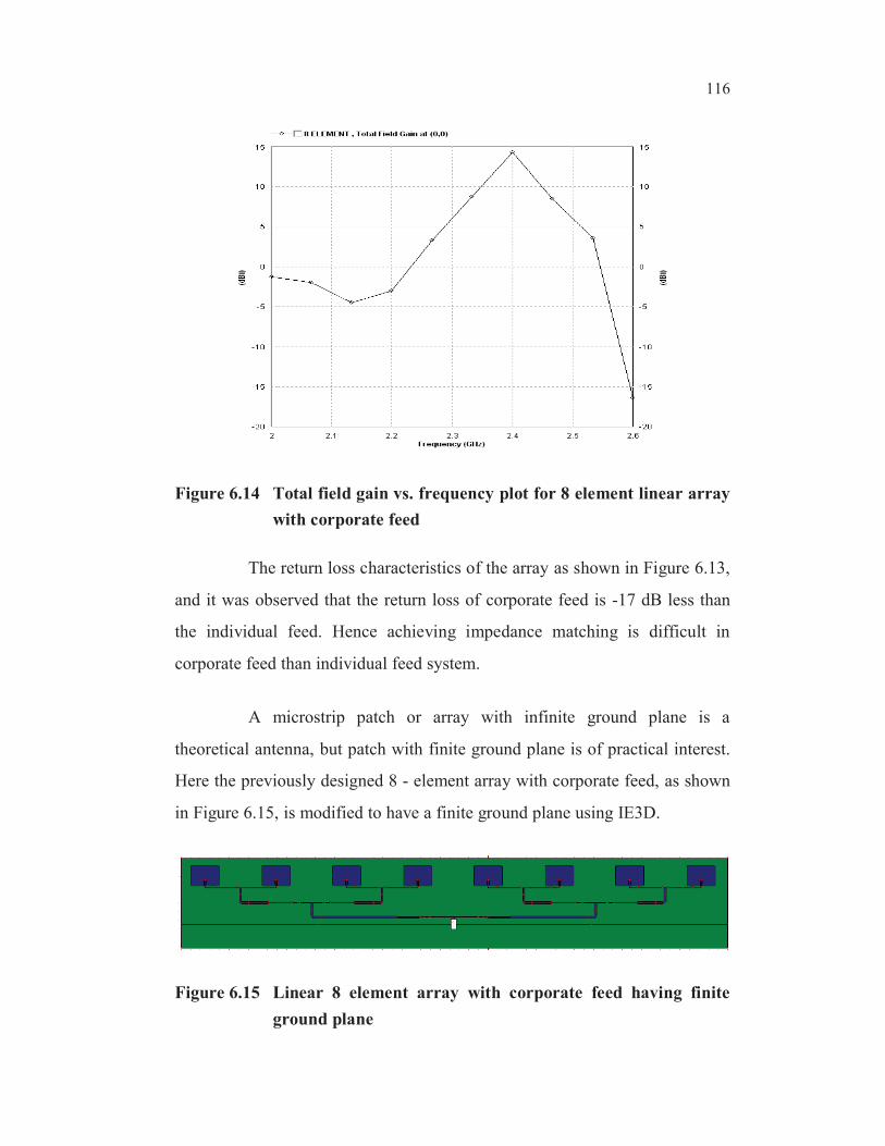
Figure 6.13 S-parameter vs. frequency plot for 8-element linear array
with corporate feed
116
Figure 6.14 Total field gain vs. frequency plot for 8 element linear array
with corporate feed
The return loss characteristics of the array as shown in Figure 6.13,
and it was observed that the return loss of corporate feed is -17 dB less than
the individual feed. Hence achieving impedance matching is difficult in
corporate feed than individual feed system.
A microstrip patch or array with infinite ground plane is a
theoretical antenna, but patch with finite ground plane is of practical interest.
Here the previously designed 8 - element array with corporate feed, as shown
in Figure 6.15, is modified to have a finite ground plane using IE3D.
Figure 6.15 Linear 8 element array with corporate feed having finite
ground plane
117
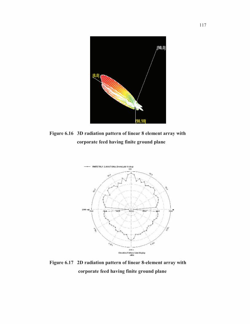
Figure 6.16 3D radiation pattern of linear 8 element array with
corporate feed having finite ground plane
Figure 6.17 2D radiation pattern of linear 8-element array with
corporate feed having finite ground plane
118
The 2D and 3D radiation pattern of 8 element linear array with
corporate feed under finite ground plane is shown in Figures 6.16 and 6.17
respectively.
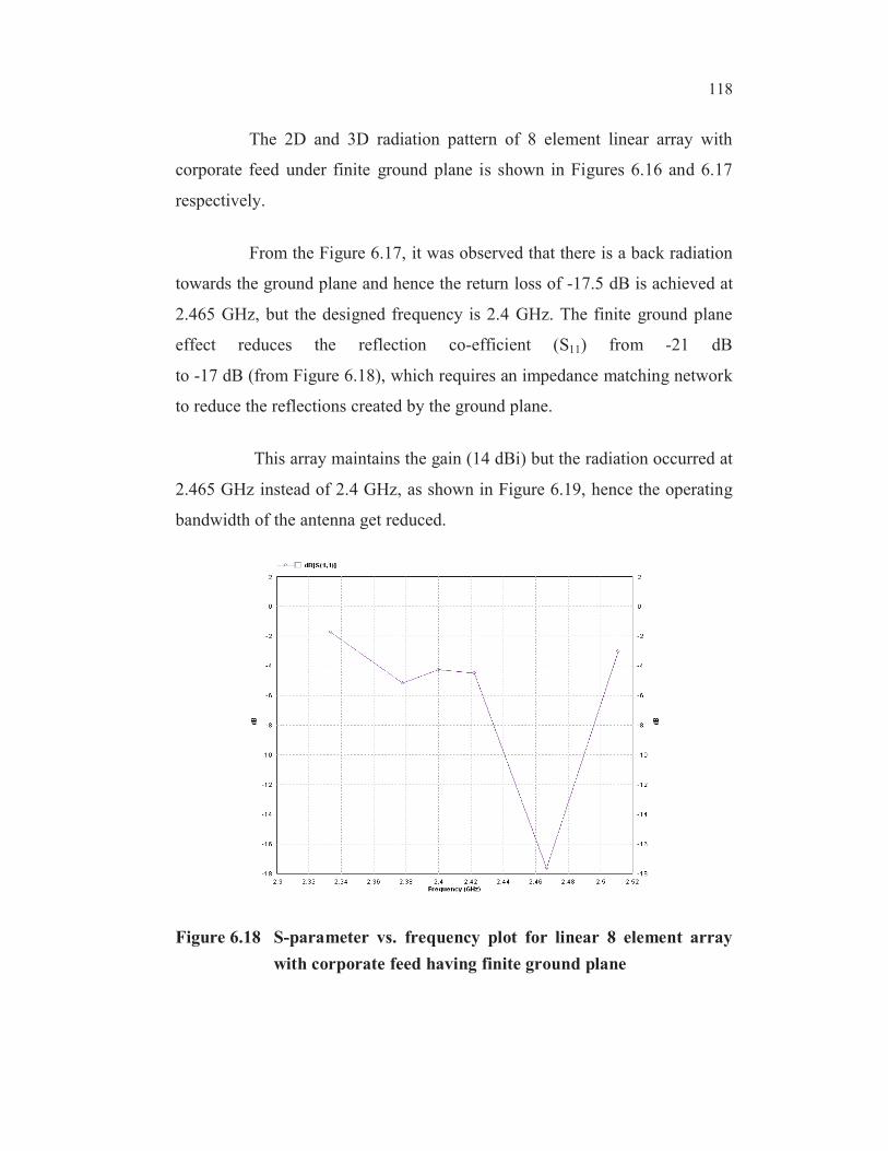
From the Figure 6.17, it was observed that there is a back radiation
towards the ground plane and hence the return loss of -17.5 dB is achieved at
2.465 GHz, but the designed frequency is 2.4 GHz. The finite ground plane
effect reduces the reflection co-efficient (S11) from -21 dB
to -17 dB (from Figure 6.18), which requires an impedance matching network
to reduce the reflections created by the ground plane.
This array maintains the gain (14 dBi) but the radiation occurred at
2.465 GHz instead of 2.4 GHz, as shown in Figure 6.19, hence the operating
bandwidth of the antenna get reduced.
Figure 6.18 S-parameter vs. frequency plot for linear 8 element array
with corporate feed having finite ground plane

119
Figure 6.19 Total field gain vs. frequency plot for linear 8-element array
with corporate feed having finite ground plane
When comparing the gain of individual feed linear array and
corporate feed linear array, there is a decrease of 2 dBi in the latter case. This
is acceptable when compared with the source cost of both the arrays.
6.3.2 Planar Array
Planar arrays are more versatile and can provide more symmetrical
patterns with lower side lobes. In addition, they can be used to scan the main
beam of the antenna towards any point in space.
Here planar array having (8x2) 16 elements with corporate feed
(2 feeds) is designed for 2.4 GHz and simulated using IE3D as shown in
Figure 6.20 with infinite ground plane.
120
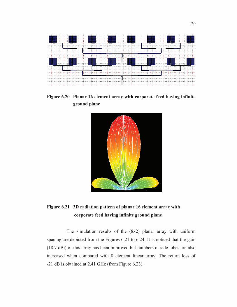
Figure 6.20 Planar 16 element array with corporate feed having infinite
ground plane
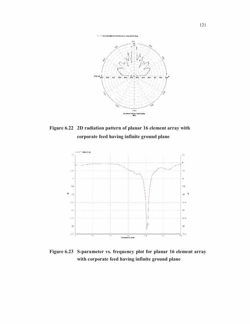
Figure 6.21 3D radiation pattern of planar 16 element array with
corporate feed having infinite ground plane
The simulation results of the (8x2) planar array with uniform
spacing are depicted from the Figures 6.21 to 6.24. It is noticed that the gain
(18.7 dBi) of this array has been improved but numbers of side lobes are also
increased when compared with 8 element linear array. The return loss of
-21 dB is obtained at 2.41 GHz (from Figure 6.23).
121
Figure 6.22 2D radiation pattern of planar 16 element array with
corporate feed having infinite ground plane
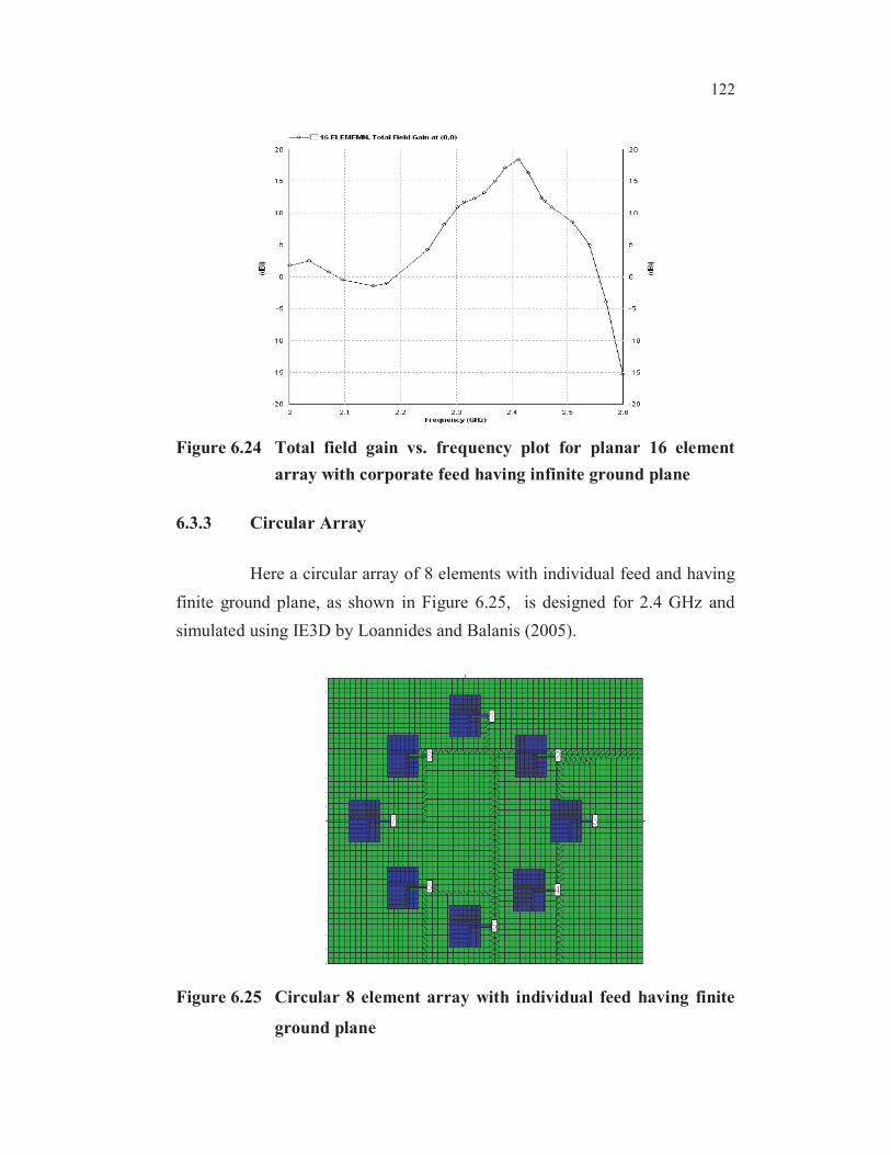
Figure 6.23 S-parameter vs. frequency plot for planar 16 element array
with corporate feed having infinite ground plane
122
Figure 6.24 Total field gain vs. frequency plot for planar 16 element
array with corporate feed having infinite ground plane
6.3.3 Circular Array
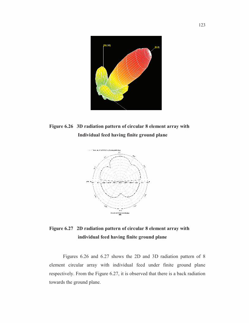
Here a circular array of 8 elements with individual feed and having
finite ground plane, as shown in Figure 6.25, is designed for 2.4 GHz and
simulated using IE3D by Loannides and Balanis (2005).
Figure 6.25 Circular 8 element array with individual feed having finite
ground plane
123
Figure 6.26 3D radiation pattern of circular 8 element array with
Individual feed having finite ground plane
Figure 6.27 2D radiation pattern of circular 8 element array with
individual feed having finite ground plane
Figures 6.26 and 6.27 shows the 2D and 3D radiation pattern of 8
element circular array with individual feed under finite ground plane
respectively. From the Figure 6.27, it is observed that there is a back radiation
towards the ground plane.
124
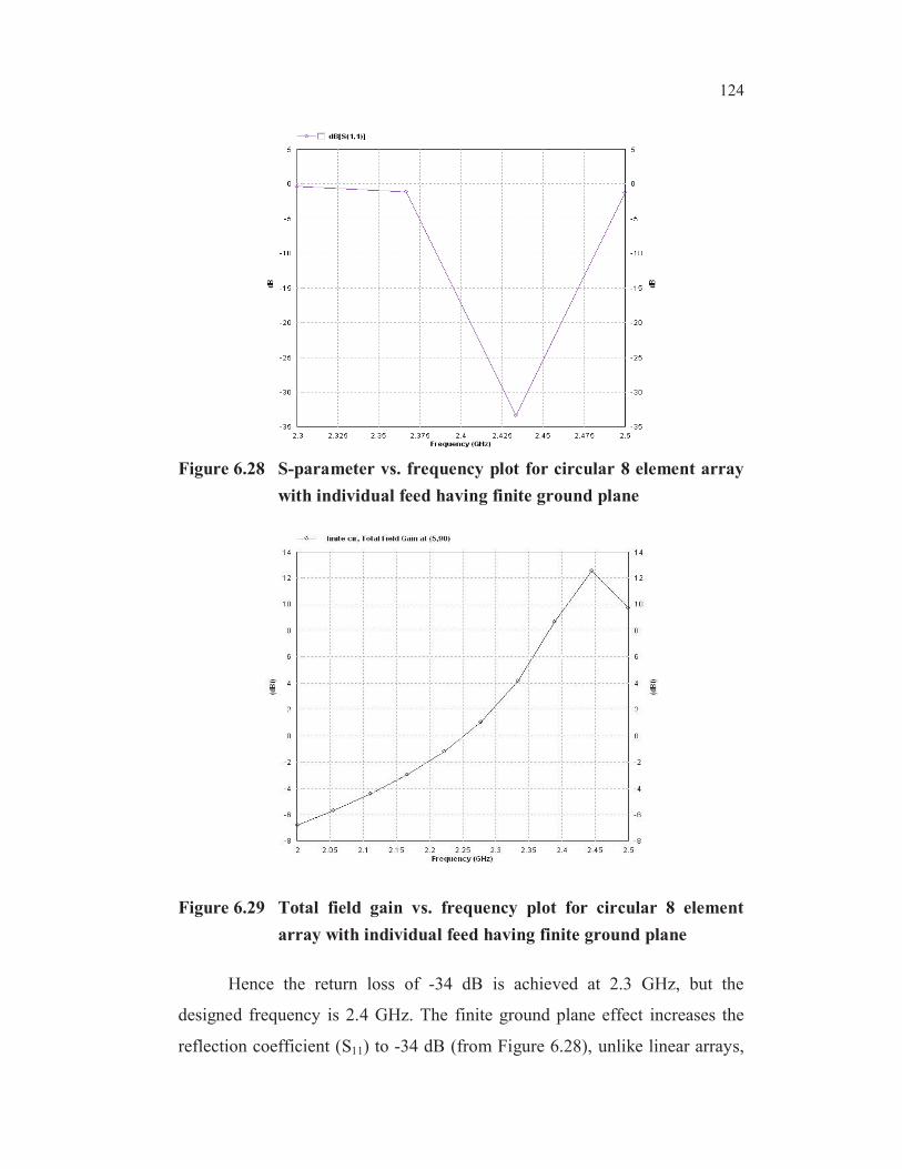
Figure 6.28 S-parameter vs. frequency plot for circular 8 element array
with individual feed having finite ground plane
Figure 6.29 Total field gain vs. frequency plot for circular 8 element
array with individual feed having finite ground plane
Hence the return loss of -34 dB is achieved at 2.3 GHz, but the
designed frequency is 2.4 GHz. The finite ground plane effect increases the
reflection coefficient (S11) to -34 dB (from Figure 6.28), unlike linear arrays,

125
it does not require an impedance matching network due to its configuration.
This array got the gain (12.5 dBi) but the radiation occurred at 2.5 GHz
instead of 2.4 GHz, as shown in Figure 6.29, hence the operating bandwidth
of the antenna get reduced.
Table 6.1 Comparisons of optimized array configurations using IE3D
with finite ground plane effects
Properties
Linear Array
(Finite
Ground)
Uniform
Planar
Circular
(Finite
Ground)
Frequency(GHz) 2.4 2.4 2.4
Incident Power(W) 0.08 0.08 0.08
Input Power (W) 0.00328395 0.00307067 0.00643603
Radiated Power(W) 0.00239989 0.000488037 0.00505084
Average Radiated Power (W/s) 0.000190977 3.88368e-005 0.000401933
Radiation Efficiency (%) 73.0794 15.8935 78.4775
Antenna Efficiency (%) 23.9989 2.44019 6.31355
Conjugate Match Efficiency (%) 36.5397 7.94676 39.2388
Voltage Source Efficiency % 11.4004 14.7947 8.36868
Total Field Properties
Gain (dBi) 8.92185 18.74999 2.42232
Directivity(dBi) 15.1199 17.8758 14.4196
3dB Beamwidth (deg) (7.91308,
58.6623)
(10.0932,
44.7466)
(27.7746,
30.6283)
Conjugate Match Gain (dBi) 10.7476 6.87766 10.3567
Voltage Source Gain (dBi) 5.6891 9.57682 3.6461
Radiated Power in Whole Space (w) 0.00239989 0.000488037 0.00505084
Radiated Power in Upper Space (w) 0.00220806 0.000488037 0.00480238
Radiated Power in Lower Space (w) 0.000191827 2.14112e-013 0.000248458
Radiation Efficiency in Whole Space (%) 73.0794 75.8935 78.4775
Radiation Efficiency in Upper Space (%) 67.238 69.7263 74.6171
Radiation Efficiency in Lower Space
(%)
5.84133 6.97281e-009 3.86043

126
6.4 RESULTS AND DISCUSSION
The optimized single patch has required return loss for the
WiMAX application but has poor directivity and gain.
From Table 6.1, it can be inferred as follows:
The different microstrip array configurations discussed found
to have the necessary gain and directivity (18 dBi) along with
optimum return loss (below -25 dB) for WiMAX application.
The individually fed linear array with 8 elements has
appreciable gain (8.9 dBi) and directivity (15.11 dBi) but has
N-1 (7 numbers) side lobes.
In individually fed linear array each element has to be excited
separately with individual source.
The linear 8-element array with corporate feed (single feed) is
economical when compared with individually fed array in case
excitation sources.
The linear 8-element array with corporate feed on a finite ground
plane is more practical in case of real time implementation. The
gain (8.9 dBi) is comparable with previous case.
Even though the linear array has higher directivity (15.11
dBi), it produces a flat beam (7.9 and 58.6 degrees, elevation
and azimuth sides respectively) which cannot be used for
smart WiMAX applications.
The simulated 16-element planar array is found to have
improved performance in case of gain (18.7 dBi) and

127
directivity (17.8 dBi) but the number of side lobes increased
when compared with 8-element linear array.
Circular configurations have highest radiated power
(0.05 Watts) and radiation efficiency (78.4 %) than any other
configurations.
By comparing all the configurations, it is found that 8-element
circular array has an optimum directivity (14.4 dBi) and
beamwidth (27.7 and 30.6 degrees, elevation and azimuth
sides respectively) which can be used for WiMAX.