Embed Size (px)
Citation preview
Chapter 6 (Oscillators)
555 Timers
Course Instructor (2EA)Ajay Kumar KadelAssistant Lecturer
Department of Electronics, Computer and Electrical EngineeringKathmandu Engineering College
Course Homepagewww.courses.esmartdesign.com
Lecture slides on 555 Timers 2
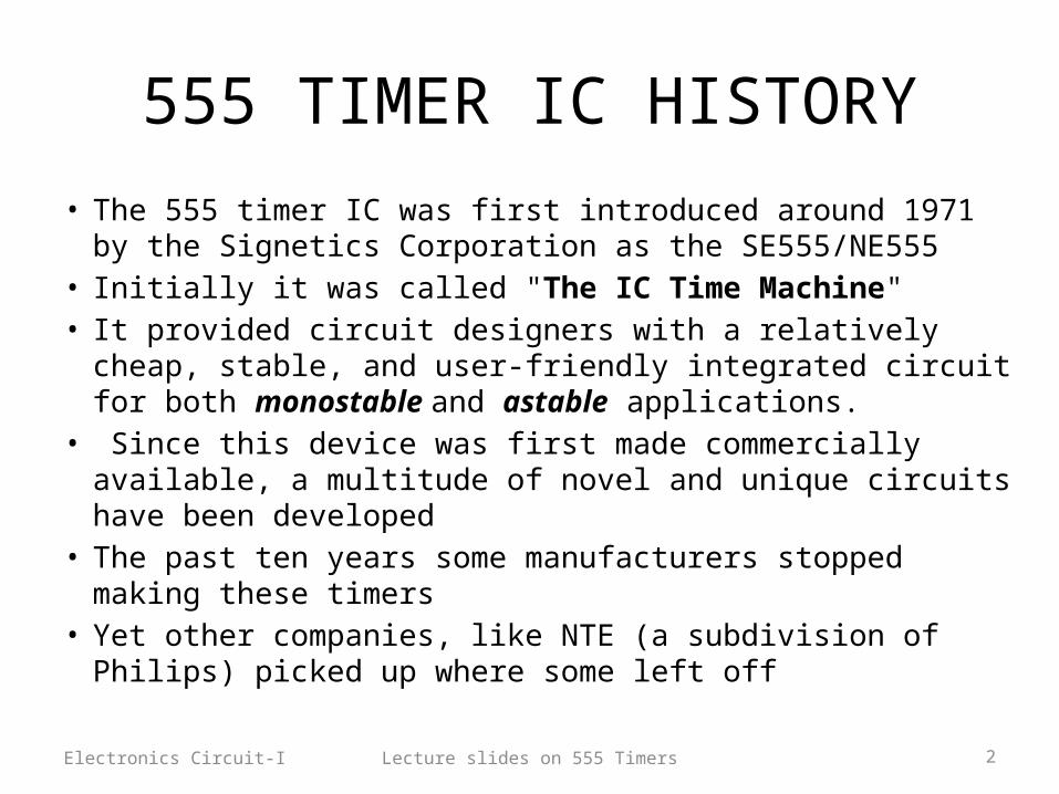
555 TIMER IC HISTORY
• The 555 timer IC was first introduced around 1971 by the Signetics Corporation as the SE555/NE555
• Initially it was called "The IC Time Machine" • It provided circuit designers with a relatively cheap, stable, and
user-friendly integrated circuit for both monostable and astable applications.
• Since this device was first made commercially available, a multitude of novel and unique circuits have been developed
• The past ten years some manufacturers stopped making these timers
• Yet other companies, like NTE (a subdivision of Philips) picked up where some left off
Electronics Circuit-I

Lecture slides on 555 Timers 3
555 Timer Schematic Diagram
It consists of 23 transistors, 2 diodes, and 16 resistors.
Electronics Circuit-I
Lecture slides on 555 Timers 4
Applications of 555 Timers
• Monostable &Astable Multivibrators
• Waveform generators• Burglar Alarms• Measurement ,Process &
Control Circuits• Missing pulse detectors• Traffic light control• Automatic Battery chargers• Logic probes• DC to DC Converters etc.
Electronics Circuit-I
Lecture slides on 555 Timers 5
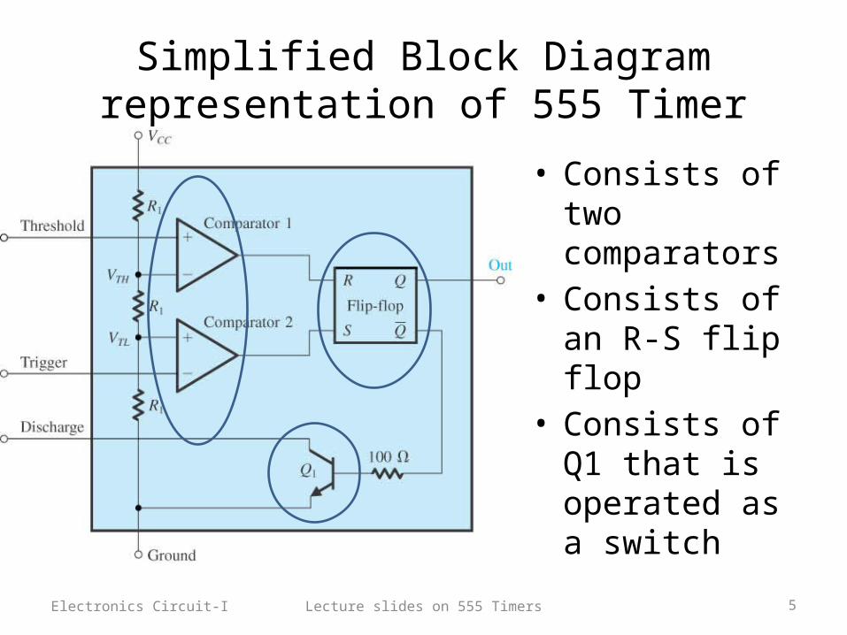
Simplified Block Diagram representation of 555 Timer
• Consists of two comparators
• Consists of an R-S flip flop
• Consists of Q1 that is operated as a switch
Electronics Circuit-I

Lecture slides on 555 Timers 6
R-S flip Flop Review
R S Q Action0 0 Last Value No change0 1 1 Set1 0 0 Reset1 1 ? Indeterminate(forbidden)
Electronics Circuit-I
Lecture slides on 555 Timers 7
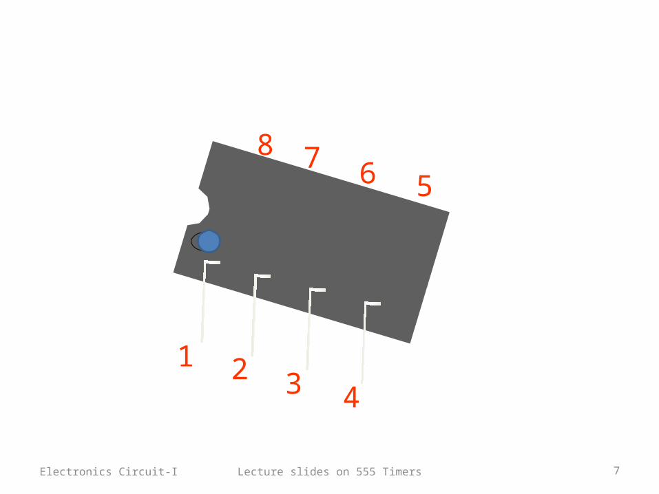
1 2 3 4
5678
Electronics Circuit-I
Lecture slides on 555 Timers 8
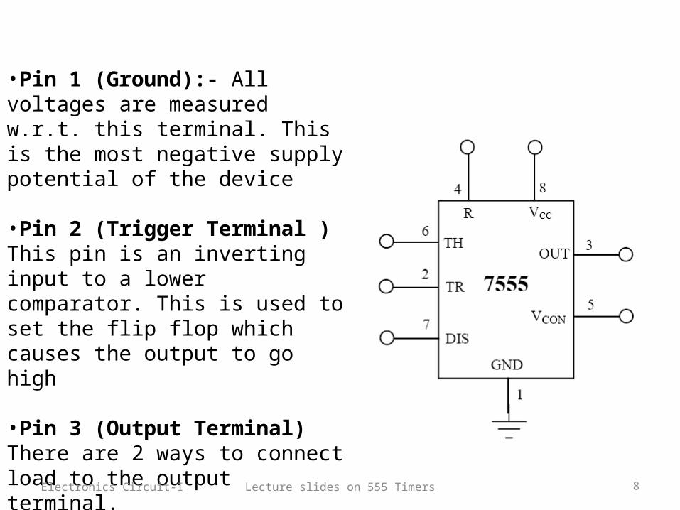
•Pin 1 (Ground):- All voltages are measured w.r.t. this terminal. This is the most negative supply potential of the device
•Pin 2 (Trigger Terminal )This pin is an inverting input to a lower comparator. This is used to set the flip flop which causes the output to go high
•Pin 3 (Output Terminal)There are 2 ways to connect load to the output terminal.Pin 3 & Vcc :- Normally On loadPin 3 & Ground:- Normally off load
Electronics Circuit-I
Lecture slides on 555 Timers 9
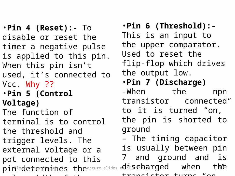
•Pin 4 (Reset):- To disable or reset the timer a negative pulse is applied to this pin. When this pin isn’t used, it’s connected to Vcc. Why ??•Pin 5 (Control Voltage)The function of terminal is to control the threshold and trigger levels. The external voltage or a pot connected to this pin determines the pulse width of the output waveform. When not in use, it should be connected to ground through a 0.01uF capacitor to avoid any noise problem.
Electronics Circuit-I
•Pin 6 (Threshold):- This is an input to the upper comparator. Used to reset the flip-flop which drives the output low.•Pin 7 (Discharge)-When the npn transistor connected to it is turned “on,” the pin is shorted to ground– The timing capacitor is usually between pin 7 and ground and is discharged when the transistor turns “on”•Pin 8 (Supply Voltage):- A positive supply voltage is applied to this terminal

Lecture slides on 555 Timers 10
BASIC TIMING CONCEPTS• A resistive voltage divider
consisting of 3 equal resistors R1 is employed
• VTH= 2Vcc/3 for comparator 1.• Flip Flop is reset whenever
threshold goes higher than 2Vcc/3.
• VTL=Vcc/3• Flip Flop is set whenever the
trigger goes below Vcc/3.• In set state output Q is high
(approx. equal to Vcc) and in reset the output is low
Electronics Circuit-I
2Vcc/3
Vcc/3
Lecture slides on 555 Timers 11
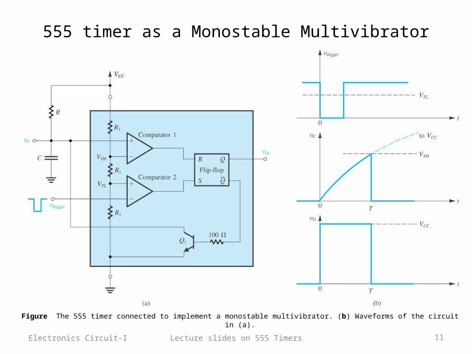
555 timer as a Monostable Multivibrator
Electronics Circuit-I
Figure The 555 timer connected to implement a monostable multivibrator. (b) Waveforms of the circuit in (a).
Lecture slides on 555 Timers 12
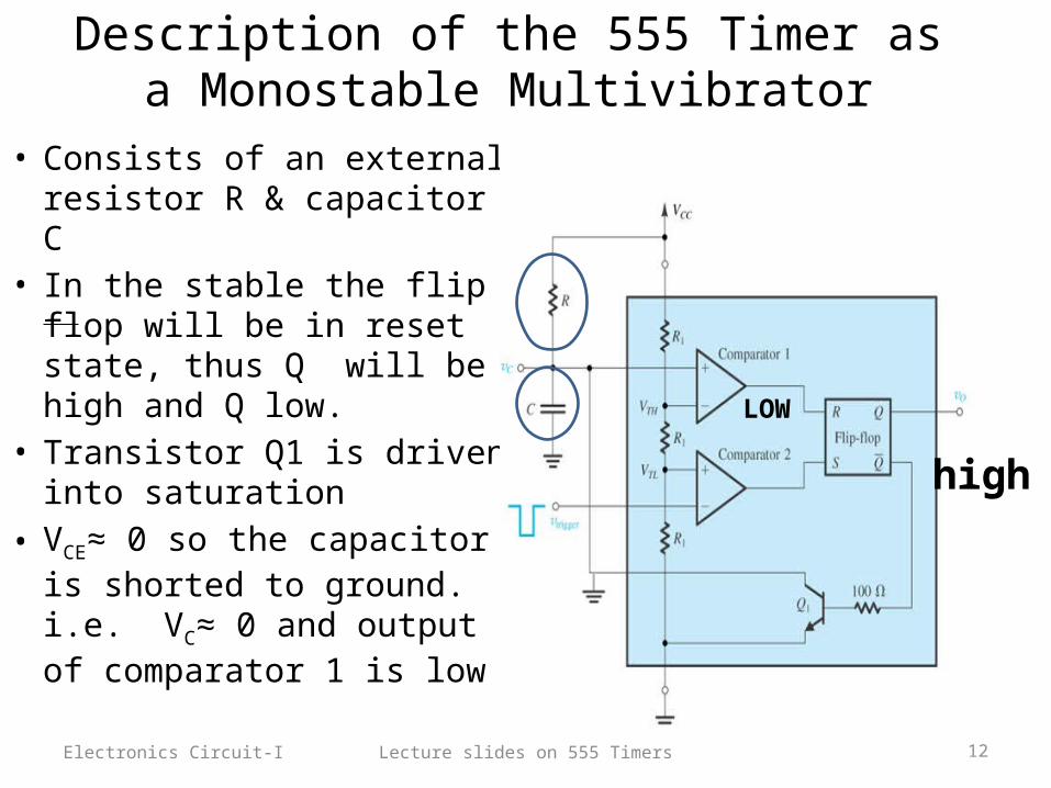
Description of the 555 Timer as a Monostable Multivibrator
• Consists of an external resistor R & capacitor C
• In the stable the flip flop will be in reset state, thus Q will be high and Q low.
• Transistor Q1 is driven into saturation
• VCE≈ 0 so the capacitor is shorted to ground. i.e. VC≈ 0 and output of comparator 1 is low
Electronics Circuit-I
high
LOW
Lecture slides on 555 Timers 13
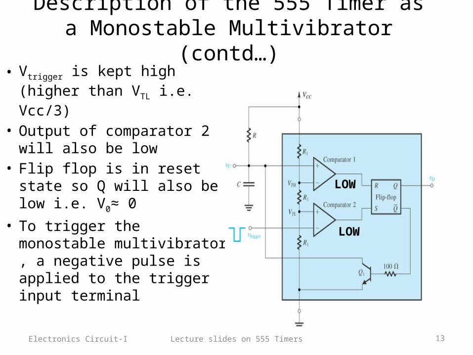
Description of the 555 Timer as a Monostable Multivibrator (contd…)
• Vtrigger is kept high (higher than VTL i.e. Vcc/3)
• Output of comparator 2 will also be low
• Flip flop is in reset state so Q will also be low i.e. V0≈ 0
• To trigger the monostable multivibrator , a negative pulse is applied to the trigger input terminal
Electronics Circuit-I
LOW
LOW

Lecture slides on 555 Timers 14
Description of the 555 Timer as a Monostable Multivibrator (contd…)
• As Vtrigger goes below VTL i.e. Vcc/3, the output of comparator 2 goes high thus setting the flip flop. i.e. Q=1 Q =0, so the transistor is cutoff
• Vtrigger is given for a short time so output of compartor 2 goes low again.
• Still the ouput is high because R=0 and S=0 result in Q to be in the previous state.
• Capacitor C now begins to charge through resistor R and Vc rises exponentially towards Vcc.
• The high voltage at the ouput is retained as long as Vc<VTH
Electronics Circuit-I
LOW
LOWHIGH
HIGH
LOWLOW

Lecture slides on 555 Timers 15
Description of the 555 Timer as a Monostable Multivibrator (contd…)
• Once Vc exceeds VTH , the output of comparator 1 goes high. Now R=1 and S=0 so Q=0
• The monostable multivibrator is now back in its stable state and is ready to receive a new triggering pulse
Electronics Circuit-I
LOW
LOW
HIGH
HIGH
HIGH LOW

Lecture slides on 555 Timers 16
Derivation for the width of the pulse in monostable multivibrator
• The width of the pulse , T is the time interval that the monostable multivibrator spends in quasi stable state.
• Denoting the time instant at which the trigger pulse is applied at t=0 , the voltage across capacitor Vc can be expressed as ,
Electronics Circuit-I
• Substituting Vc=VTH=2/3Vcc at t=T gives,
T=RC ln 3 =1.1 RC

Figure 13.28 (a) The 555 timer connected to implement a monostable multivibrator. (b) Waveforms of the circuit in (a).
Lecture slides on 555 Timers 18
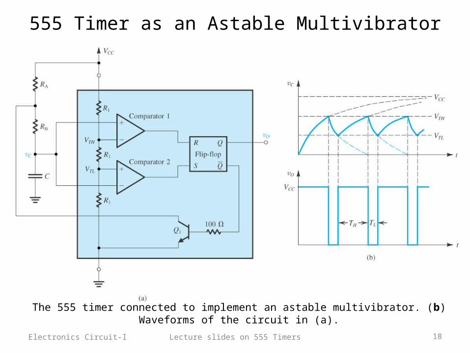
555 Timer as an Astable Multivibrator
Electronics Circuit-I
The 555 timer connected to implement an astable multivibrator. (b) Waveforms of the circuit in (a).

Lecture slides on 555 Timers 19
Description of 555 timer as an Astable Multivibrator
• Please refer to the handout of 555 timer provided to you.
Electronics Circuit-I