Embed Size (px)
Citation preview
1
Chapter 6: PipeliningChapter 6: Pipelining
2
OutlineOutline
An overview of pipeliningA pipelined datapathPipelined controlData hazards and forwardingData hazards and stallsBranch hazardsExceptionsSuperscalar and dynamic pipelining
3
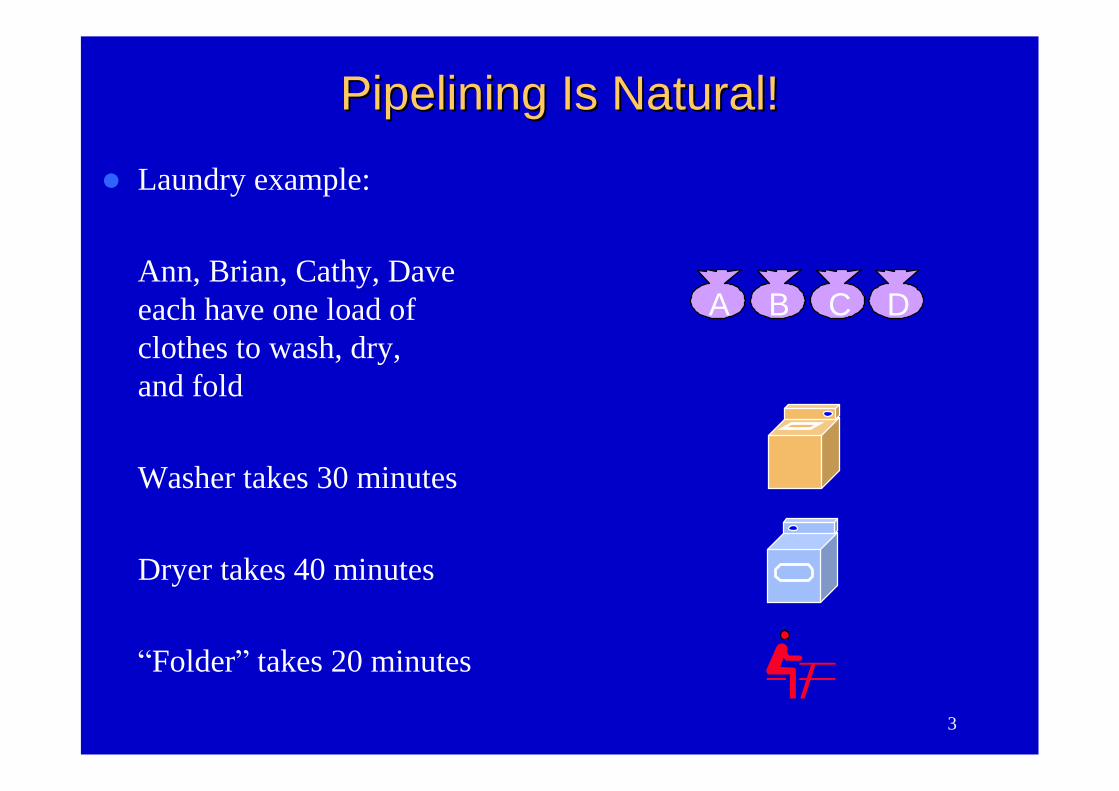
Laundry example:
Ann, Brian, Cathy, Daveeach have one load ofclothes to wash, dry,and fold
Washer takes 30 minutes
Dryer takes 40 minutes
“Folder”takes 20 minutes
A B C D
Pipelining Is Natural!Pipelining Is Natural!
4
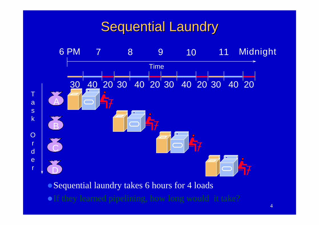
Sequential laundry takes 6 hours for 4 loadsIf they learned pipelining, how long would it take?
A
B
C
D
30 40 20 30 40 20 30 40 20 30 40 20
6 PM 7 8 9 10 11 Midnight
Task
Order
Time
Sequential LaundrySequential Laundry
5
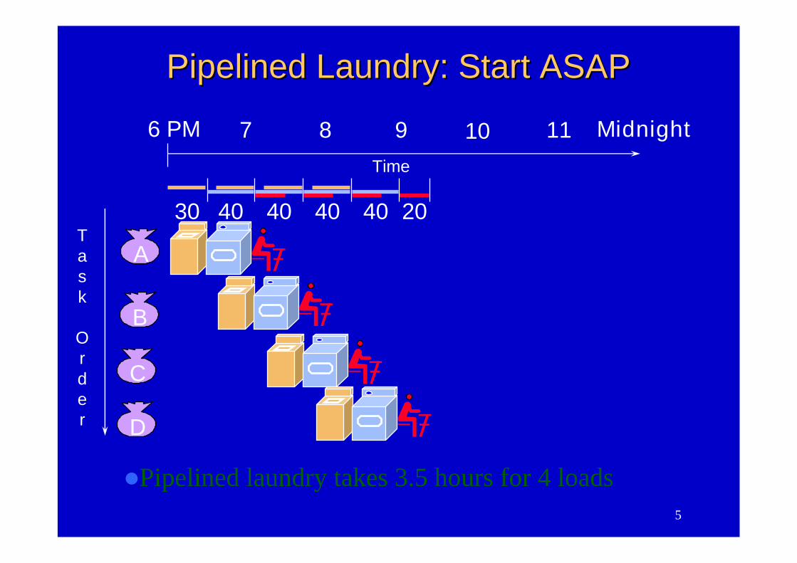
Pipelined laundry takes 3.5 hours for 4 loads
A
B
C
D
6 PM 7 8 9 10 11 Midnight
Task
Order
Time
30 40 40 40 40 20
Pipelined Laundry: Start ASAPPipelined Laundry: Start ASAP
6
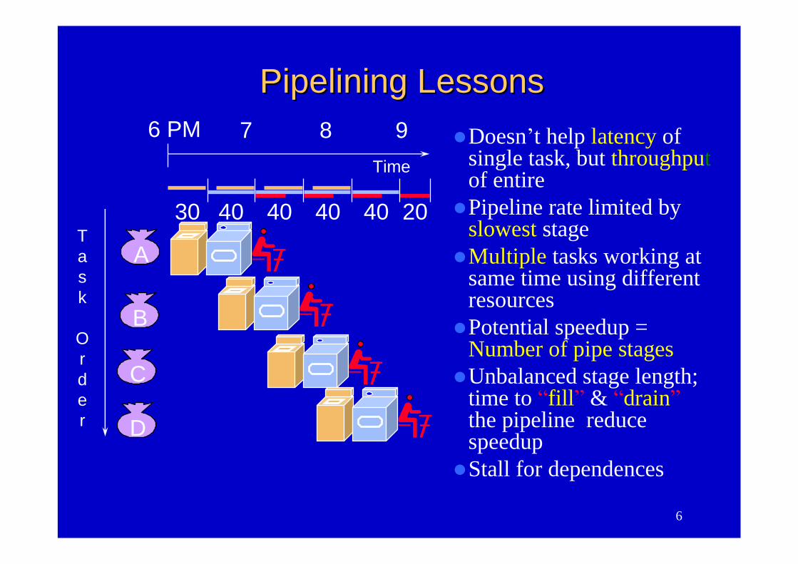
Pipelining LessonsPipelining LessonsDoesn’t help latency of
single task, but throughputof entirePipeline rate limited by
slowest stageMultiple tasks working at
same time using differentresourcesPotential speedup =
Number of pipe stagesUnbalanced stage length;
time to “fill”& “drain”the pipeline reducespeedupStall for dependences
A
B
C
D
6 PM 7 8 9
Task
Order
Time
30 40 40 40 40 20
7
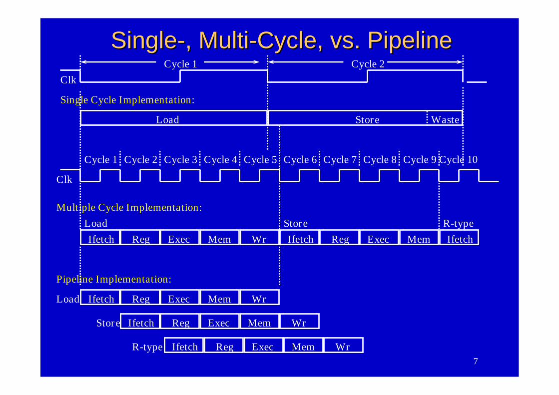
SingleSingle--, Multi, Multi--Cycle, vs. PipelineCycle, vs. Pipeline
Clk
Cycle 1
Multiple Cycle Implementation:
Ifetch Reg Exec Mem Wr
Cycle 2 Cycle 3 Cycle 4 Cycle 5 Cycle 6 Cycle 7 Cycle 8 Cycle 9 Cycle 10
Load Ifetch Reg Exec Mem Wr
Ifetch Reg Exec MemLoad Store
Pipeline Implementation:
Ifetch Reg Exec Mem WrStore
Clk
Single Cycle Implementation:
Load Store Waste
IfetchR-type
Ifetch Reg Exec Mem WrR-type
Cycle 1 Cycle 2
8
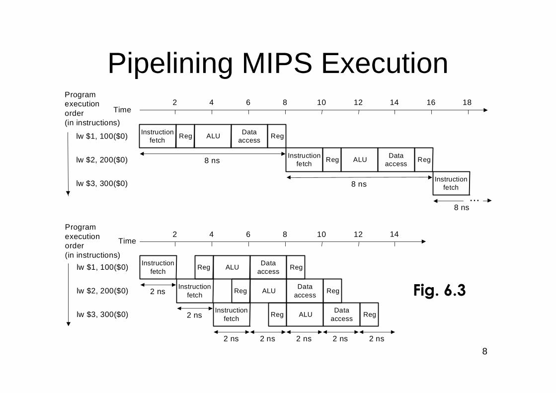
Pipelining MIPS Execution
Instructionfetch
Reg ALU Dataaccess
Reg
8 nsInstruction
fetchReg ALU Data
accessReg
8 nsInstruction
fetch
8 ns
Time
lw $1, 100($0)
lw $2, 200($0)
lw $3, 300($0)
2 4 6 8 10 12 14 16 18
2 4 6 8 10 12 14
...
Programexecutionorder(in instructions)
Instructionfetch
Reg ALUData
accessReg
Time
lw $1, 100($0)
lw $2, 200($0)
lw $3, 300($0)
2 nsInstruction
fetchReg ALU
Dataaccess
Reg
2 nsInstruction
fetchReg ALU
Dataaccess
Reg
2 ns 2 ns 2 ns 2 ns 2 ns
Programexecutionorder(in instructions)
Fig. 6.3
9
Instr.
Order
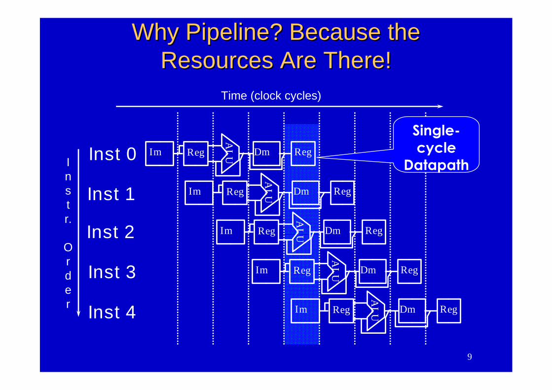
Time (clock cycles)
Inst 0
Inst 1
Inst 2
Inst 4
Inst 3A
LUIm Reg Dm Reg
AL
UIm Reg Dm Reg
AL
UIm Reg Dm Reg
AL
UIm Reg Dm Reg
AL
UIm Reg Dm Reg
Why Pipeline? Because theWhy Pipeline? Because theResources Are There!Resources Are There!
Single-cycle
Datapath
10
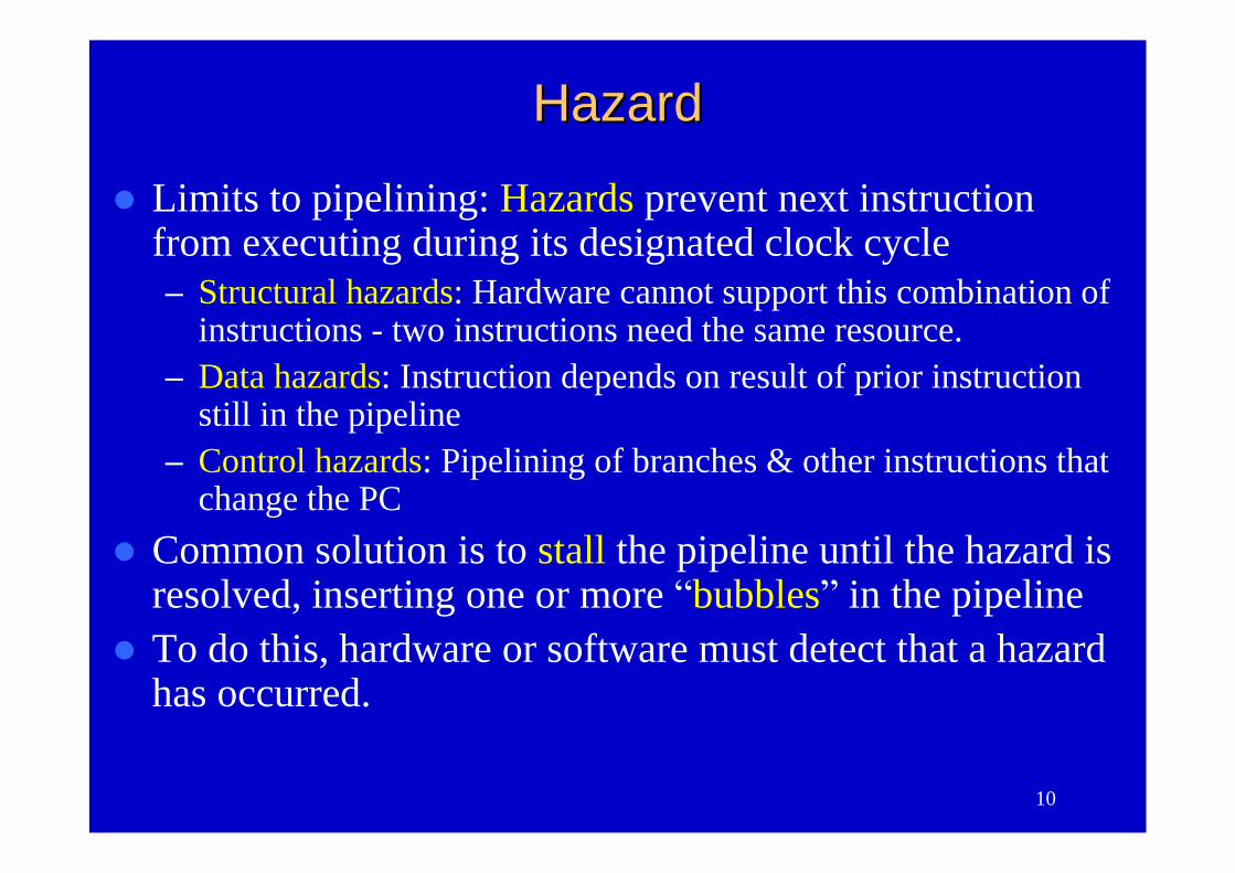
HazardHazard
Limits to pipelining: Hazards prevent next instructionfrom executing during its designated clock cycle–Structural hazards: Hardware cannot support this combination of
instructions - two instructions need the same resource.–Data hazards: Instruction depends on result of prior instruction
still in the pipeline–Control hazards: Pipelining of branches & other instructions that
change the PCCommon solution is to stall the pipeline until the hazard is
resolved, inserting one or more “bubbles”in the pipelineTo do this, hardware or software must detect that a hazard
has occurred.
11
Structural HazardsStructural Hazards
Structural hazards occur when two or more instructionsneed the same resource.
Common methods for eliminating structural hazards are:– Duplicate resources– Pipeline the resource– Reorder the instructions
It may be too expensive too eliminate a structural hazard,in which case the pipeline should stall.
When the pipeline stalls, no instructions are issued untilthe hazard has been resolved.
What are some examples of structural hazards?
12
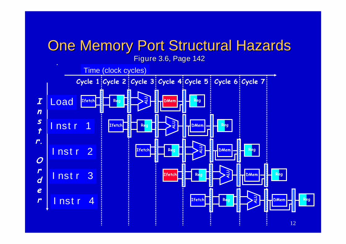
One Memory Port Structural HazardsOne Memory Port Structural HazardsFigure 3.6, Page 142Figure 3.6, Page 142
Time (clock cycles)
Instr.
Order
Load
Instr 1
Instr 2
Instr 3
Instr 4
Reg ALU DMemIfetch Reg
Reg ALU DMemIfetch Reg
Reg ALU DMemIfetch Reg
Reg ALU DMemIfetch Reg
Cycle 1 Cycle 2 Cycle 3 Cycle 4 Cycle 6 Cycle 7Cycle 5
Reg ALU DMemIfetch Reg
13
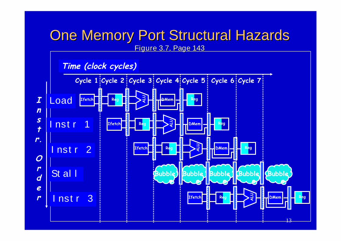
One Memory Port Structural HazardsOne Memory Port Structural HazardsFigure 3.7, Page 143Figure 3.7, Page 143
Instr.
Order
Time (clock cycles)
Load
Instr 1
Instr 2
Stall
Instr 3
Reg ALU DMemIfetch Reg
Reg ALU DMemIfetch Reg
Reg ALU DMemIfetch Reg
Cycle 1 Cycle 2 Cycle 3 Cycle 4 Cycle 6 Cycle 7Cycle 5
Reg ALU DMemIfetch Reg
Bubble Bubble Bubble BubbleBubble
14
OutlineOutline
An overview of pipeliningA pipelined datapath (6.2)Pipelined controlData hazards and forwardingData hazards and stallsBranch hazardsExceptionsSuperscalar and dynamic pipelining
15
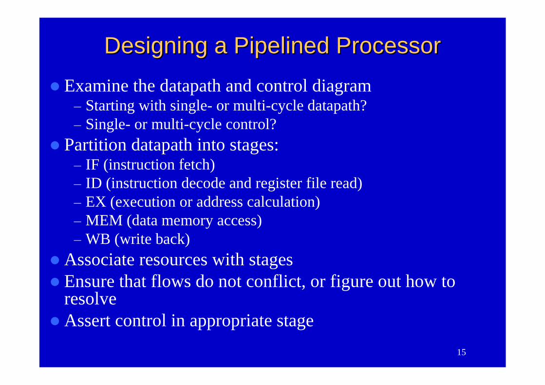
Designing a Pipelined ProcessorDesigning a Pipelined Processor
Examine the datapath and control diagram–Starting with single- or multi-cycle datapath?–Single- or multi-cycle control?
Partition datapath into stages:–IF (instruction fetch)–ID (instruction decode and register file read)–EX (execution or address calculation)–MEM (data memory access)–WB (write back)
Associate resources with stagesEnsure that flows do not conflict, or figure out how to
resolveAssert control in appropriate stage
16
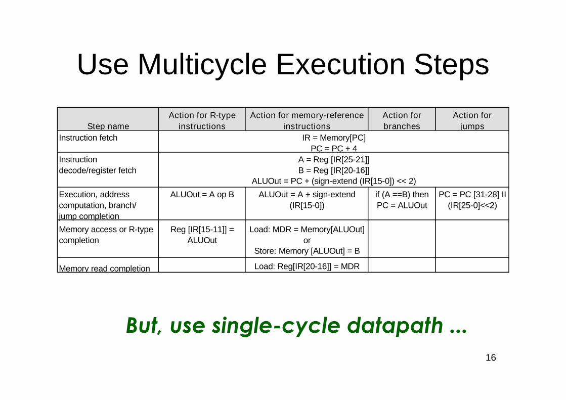
Use Multicycle Execution Steps
Step nameAction for R-type
instructionsAction for memory-reference
instructionsAction forbranches
Action forjumps
Instruction fetch IR = Memory[PC]PC = PC + 4
Instruction A = Reg [IR[25-21]]decode/register fetch B = Reg [IR[20-16]]
ALUOut = PC + (sign-extend (IR[15-0]) << 2)
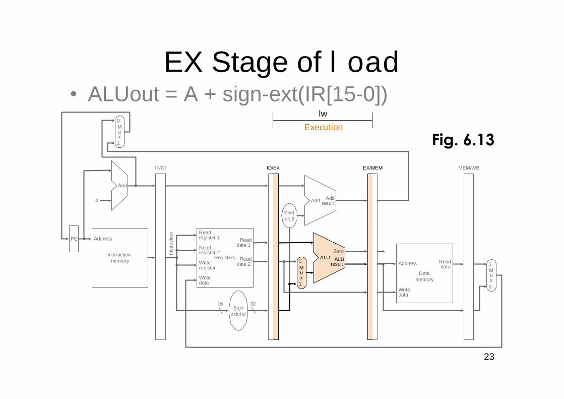
Execution, address ALUOut = A op B ALUOut = A + sign-extend if (A ==B) then PC = PC [31-28] IIcomputation, branch/ (IR[15-0]) PC = ALUOut (IR[25-0]<<2)jump completion
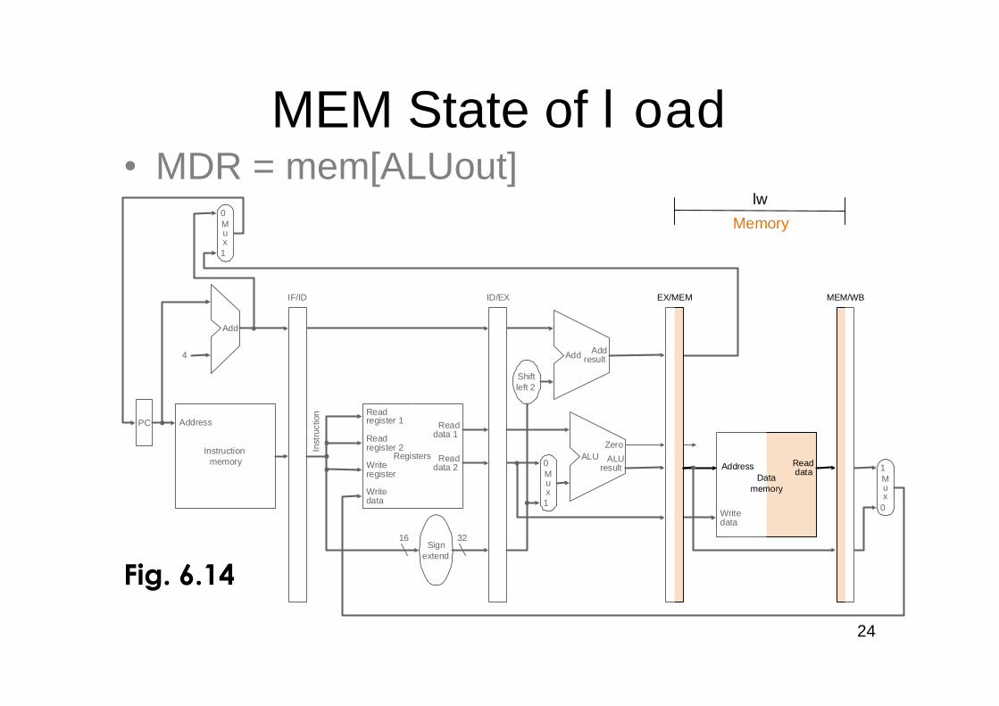
Memory access or R-type Reg [IR[15-11]] = Load: MDR = Memory[ALUOut]completion ALUOut or
Store: Memory [ALUOut] = B
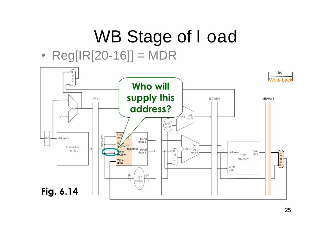
Memory read completion Load: Reg[IR[20-16]] = MDR
But, use single-cycle datapath ...
17
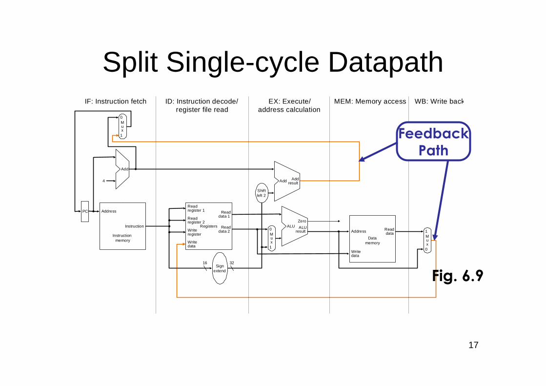
Split Single-cycle Datapath
Instructionmemory
Address
4
32
0
Add Addresult
Shiftleft 2
Instruction
Mux
0
1
Add
PC
0Writedata
Mux
1Registers
Readdata 1
Readdata 2
Readregister 1
Readregister 2
16Sign
extend
Writeregister
Writedata
ReaddataAddress
Datamemory
1
ALUresult
Mux
ALUZero
IF: Instruction fetch ID: Instruction decode/register file read
EX: Execute/address calculation
MEM: Memory access WB: Write back
Fig. 6.9
FeedbackPath
18
Instructionmemory
Address
4
32
0
Add Addresult
Shiftleft 2
Inst
ruct
ion
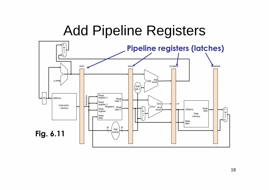
IF/ID EX/MEM MEM/WB
Mux
0
1
Add
PC
0Writedata
Mux
1Registers
Readdata 1
Readdata 2
Readregister 1
Readregister 2
16Sign
extend
Writeregister
Writedata
Readdata
1
ALUresult
Mux
ALUZero
ID/EX
Datamemory
Address
Pipeline registers (latches)
Add Pipeline Registers
Fig. 6.11
19
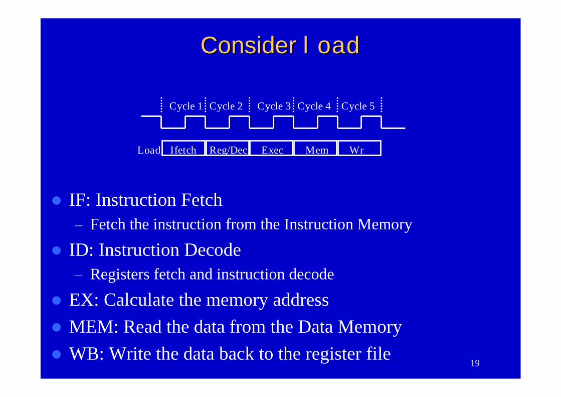
IF: Instruction Fetch–Fetch the instruction from the Instruction Memory
ID: Instruction Decode–Registers fetch and instruction decode
EX: Calculate the memory addressMEM: Read the data from the Data MemoryWB: Write the data back to the register file
Cycle 1 Cycle 2 Cycle 3 Cycle 4 Cycle 5
Ifetch Reg/Dec Exec Mem WrLoad
ConsiderConsider loadload
20
Clock
Cycle 1 Cycle 2 Cycle 3 Cycle 4 Cycle 5 Cycle 6 Cycle 7
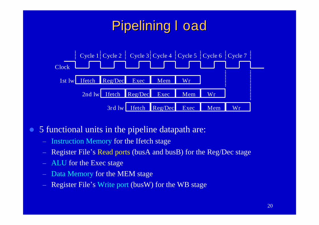
Ifetch Reg/Dec Exec Mem Wr1st lw
Ifetch Reg/Dec Exec Mem Wr2nd lw
Ifetch Reg/Dec Exec Mem Wr3rd lw
PipeliningPipelining loadload
5 functional units in the pipeline datapath are:– Instruction Memory for the Ifetch stage– Register File’s Read ports (busA and busB) for the Reg/Dec stage– ALU for the Exec stage– Data Memory for the MEM stage– Register File’s Write port (busW) for the WB stage
21
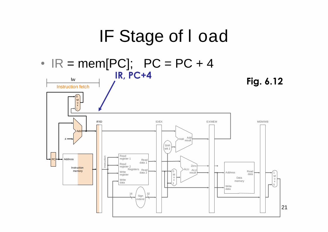
•IR = mem[PC]; PC = PC + 4
IF Stage of load
Instructionmemory
Address
4
32
0
Add Addresult
Shiftleft 2
Inst
ruct
ion
IF/ID EX/MEM MEM/WB
Mux
0
1
Add
PC
0Writedata
Mux
1Registers
Readdata 1
Readdata 2
Readregister 1
Readregister 2
16Sign
extend
Writeregister
Writedata
Readdata
1
ALUresult
Mux
ALUZero
ID/EX
Instruction fetch
lw
Address
Datamemory
IR, PC+4Fig. 6.12
22
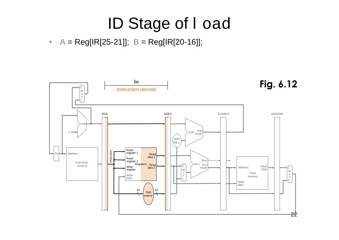
ID Stage of load• A = Reg[IR[25-21]]; B = Reg[IR[20-16]];
ALUout = PC + (sign-ext(IR[15-0]) << 2) (some ops moved to thenext stage)
Instructionmemory
Address
4
32
0
Add Addresult
Shiftleft 2
Inst
ruct
ion
IF/ID EX/MEM
Mux
0
1
Add
PC
0Writedata
Mux
1Registers
Readdata 1
Readdata 2
Readregister 1
Readregister 2
16Sign
extend
Writeregister
Writedata
Readdata
1
ALUresult
Mux
ALUZero
ID/EX MEM/WB
Instruction decode
lw
Address
Datamemory
Fig. 6.12
23
EX Stage of load•ALUout = A + sign-ext(IR[15-0])
Instructionmemory
Address
4
32
0
Add Addresult
Shiftleft 2
Inst
ruct
ion
IF/ID EX/MEM
Mux
0
1
Add
PC
0Writedata
Mux
1Registers
Readdata 1
Readdata 2
Readregister 1
Readregister 2
16Sign
extend
Writeregister
Writedata
Readdata
1
ALUresult
Mux
ALUZero
ID/EX MEM/WB
Execution
lw
Address
Datamemory
Fig. 6.13
24
MEM State of load•MDR = mem[ALUout]
Instructionmemory
Address
4
32
0
Add Addresult
Shiftleft 2
Inst
ruct
ion
IF/ID EX/MEM
Mux
0
1
Add
PC
0Writedata
Mux
1Registers
Readdata 1
Readdata 2
Readregister 1
Readregister 2
16Sign
extend
Writeregister
Writedata
Readdata
Datamemory
1
ALUresult
Mux
ALUZero
ID/EX MEM/WB
Memory
lw
Address
Fig. 6.14
25
WB Stage of load•Reg[IR[20-16]] = MDR
Instructionmemory
Address
4
32
0
Add Addresult
Shiftleft 2
Inst
ruct
ion
IF/ID EX/MEM
Mux
0
1
Add
PC
0Writedata
Mux
1Registers
Readdata 1
Readdata 2
Readregister 1
Readregister 2
16Sign
extend
Writedata
ReaddataData
memory
1
ALUresult
Mux
ALUZero
ID/EX MEM/WB
Write backlw
Writeregister
Address
Fig. 6.14
Who willsupply thisaddress?
26
Cycle 1 Cycle 2 Cycle 3 Cycle 4
Ifetch Reg/Dec Exec WrR-type
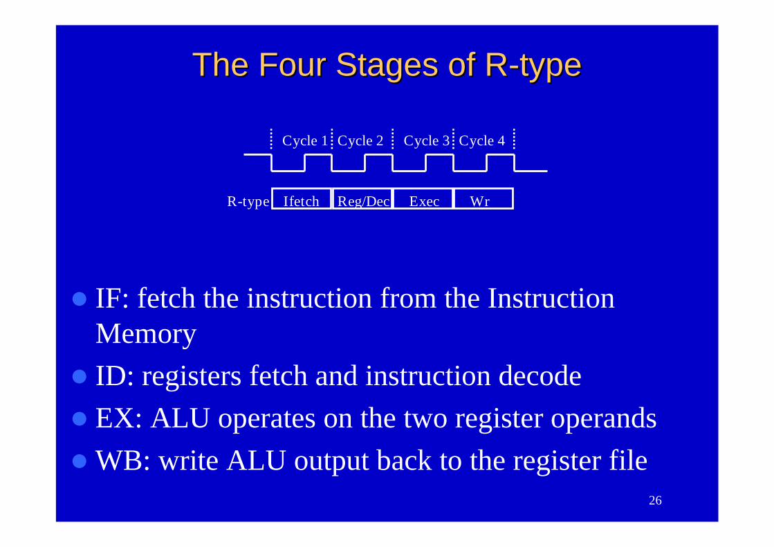
The Four Stages of RThe Four Stages of R--typetype
IF: fetch the instruction from the InstructionMemory
ID: registers fetch and instruction decodeEX: ALU operates on the two register operandsWB: write ALU output back to the register file
27
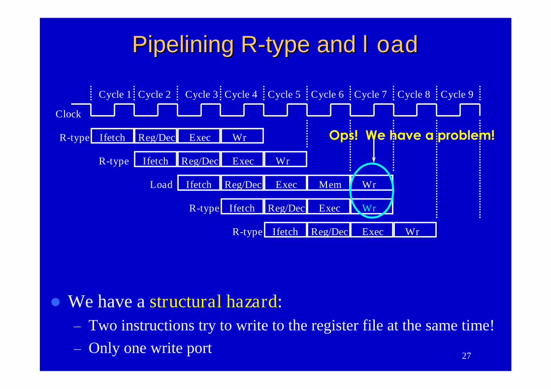
We have a structural hazard:–Two instructions try to write to the register file at the same time!–Only one write port
Clock
Cycle 1 Cycle 2 Cycle 3 Cycle 4 Cycle 5 Cycle 6 Cycle 7 Cycle 8 Cycle 9
Ifetch Reg/Dec Exec WrR-type
Ifetch Reg/Dec Exec WrR-type
Ifetch Reg/Dec Exec Mem WrLoad
Ifetch Reg/Dec Exec WrR-type
Ifetch Reg/Dec Exec WrR-type
Ops! We have a problem!
Pipelining RPipelining R--type andtype and loadload
28
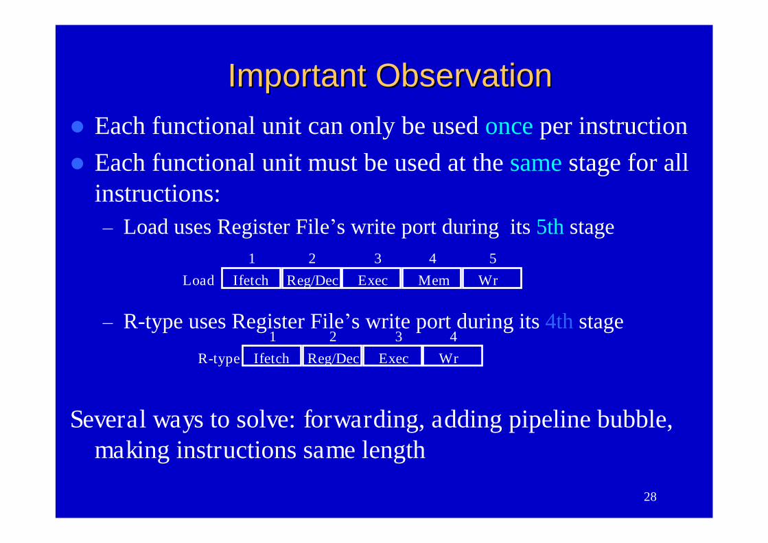
Important ObservationImportant Observation
Ifetch Reg/Dec Exec Mem WrLoad1 2 3 4 5
Ifetch Reg/Dec Exec WrR-type1 2 3 4
Each functional unit can only be used once per instructionEach functional unit must be used at the same stage for all
instructions:–Load uses Register File’s write port during its 5th stage
–R-type uses Register File’s write port during its 4th stage
Several ways to solve: forwarding, adding pipeline bubble,making instructions same length
29
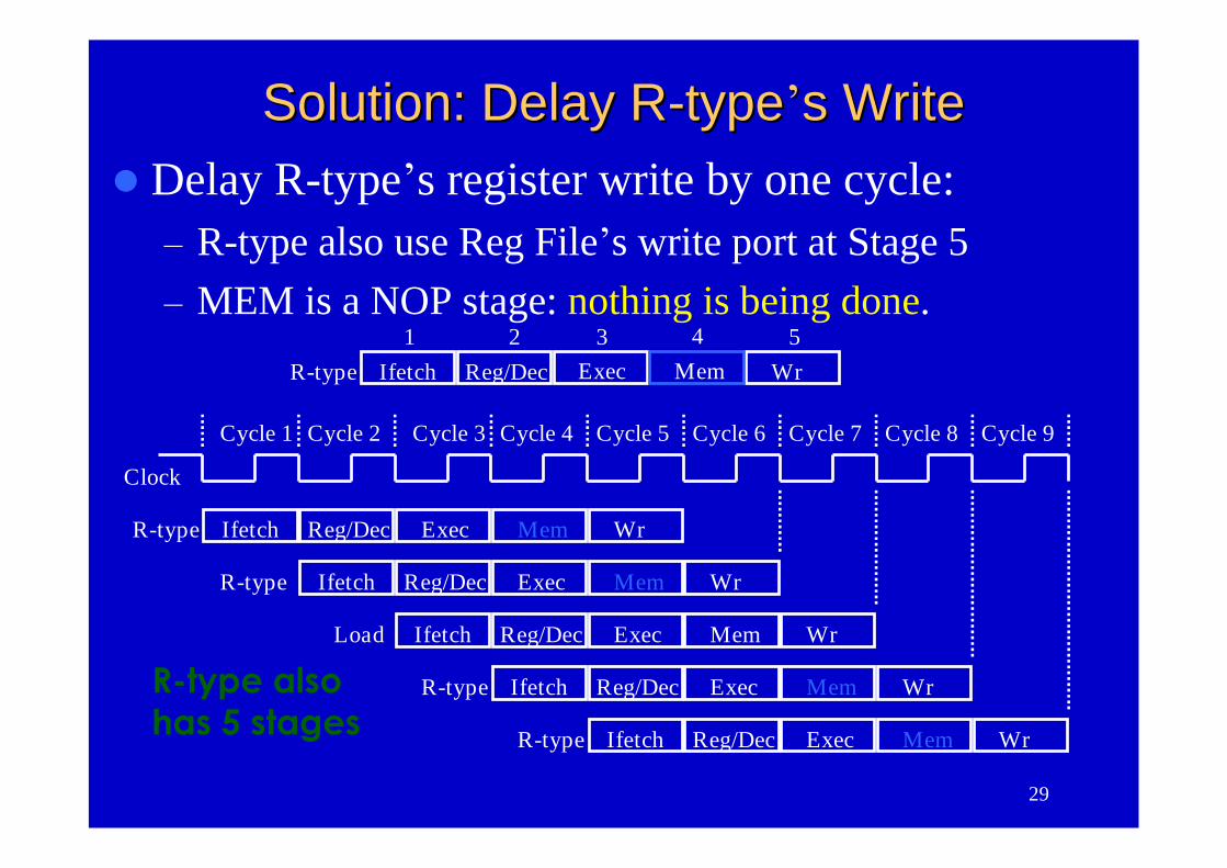
Clock
Cycle 1 Cycle 2 Cycle 3 Cycle 4 Cycle 5 Cycle 6 Cycle 7 Cycle 8 Cycle 9
Ifetch Reg/Dec Mem WrR-type
Ifetch Reg/Dec Mem WrR-type
Ifetch Reg/Dec Exec Mem WrLoad
Ifetch Reg/Dec Mem WrR-type
Ifetch Reg/Dec Mem WrR-type
Ifetch Reg/Dec Exec WrR-type Mem
Exec
Exec
Exec
Exec
1 2 3 4 5
Solution: Delay RSolution: Delay R--typetype’’s Writes WriteDelay R-type’s register write by one cycle:
–R-type also use Reg File’s write port at Stage 5–MEM is a NOP stage: nothing is being done.
R-type alsohas 5 stages
30
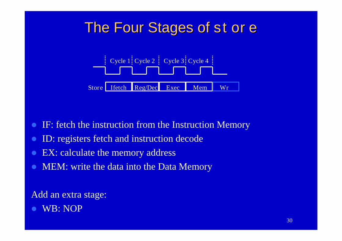
Cycle 1 Cycle 2 Cycle 3 Cycle 4
Ifetch Reg/Dec Exec MemStore Wr
The Four Stages ofThe Four Stages of storestore
IF: fetch the instruction from the Instruction Memory ID: registers fetch and instruction decode EX: calculate the memory address MEM: write the data into the Data Memory
Add an extra stage: WB: NOP
31
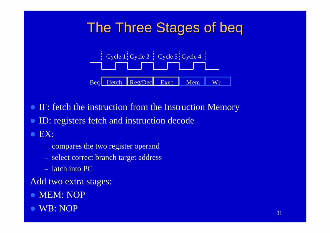
IF: fetch the instruction from the Instruction Memory ID: registers fetch and instruction decodeEX:
–compares the two register operand–select correct branch target address–latch into PC
Add two extra stages:MEM: NOPWB: NOP
Cycle 1 Cycle 2 Cycle 3 Cycle 4
Ifetch Reg/Dec Exec MemBeq Wr
The Three Stages ofThe Three Stages of beqbeq
32
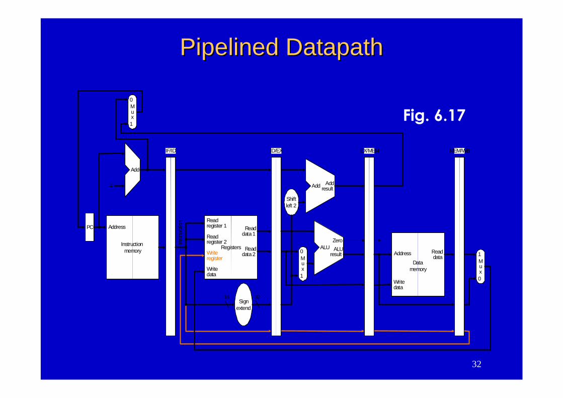
PipelinedPipelined DatapathDatapath
Instructionmemory
Address
4
32
0
Add Addresult
Shiftleft 2
Inst
ruct
ion
IF/ID EX/MEM MEM/WB
Mux
0
1
Add
PC
0
Address
Writedata
Mux
1Registers
Readdata1
Readdata2
Readregister 1
Readregister 2
16Sign
extend
Writeregister
Writedata
Readdata
Datamemory
1
ALUresult
Mux
ALUZero
ID/EX
Fig. 6.17
33
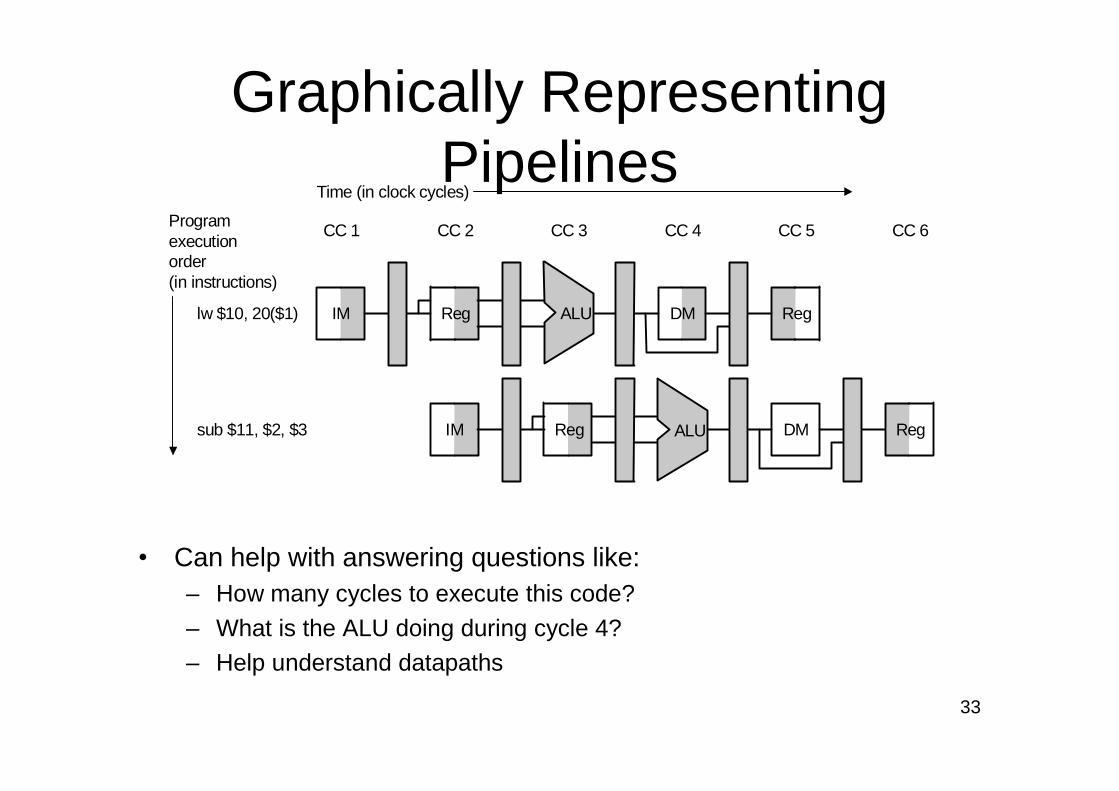
Graphically RepresentingPipelines
• Can help with answering questions like:– How many cycles to execute this code?– What is the ALU doing during cycle 4?– Help understand datapaths
IM Reg DM Reg
IM Reg DM Reg
CC 1 CC 2 CC 3 CC 4 CC 5 CC 6
Time (in clock cycles)
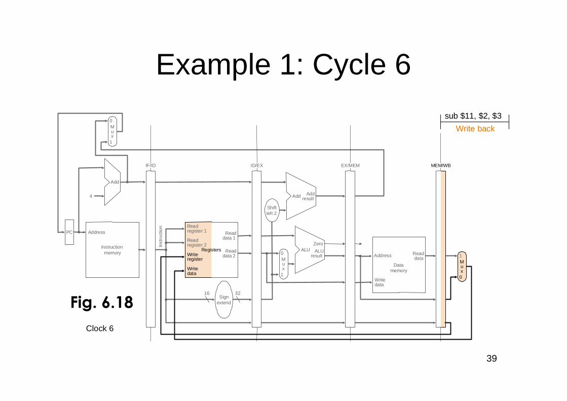
lw $10, 20($1)
Programexecutionorder(in instructions)
sub $11, $2, $3
ALU
ALU
34
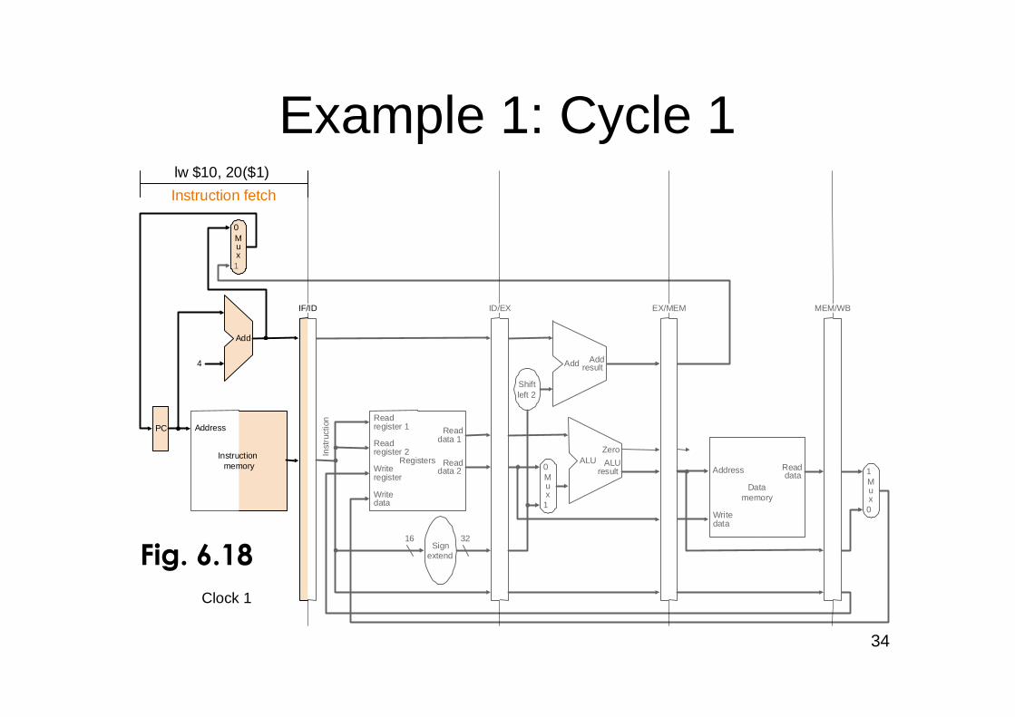
Example 1: Cycle 1
Instructionmemory
Address
4
32
0
Add Addresult
Shiftleft 2
Inst
ruct
ion
IF/ID EX/MEM MEM/WB
Mux
0
1
Add
PC
0Writedata
Mux
1Registers
Readdata 1
Readdata 2
Readregister 1
Readregister 2
16Sign
extend
Writeregister
Writedata
Readdata
1
ALUresult
Mux
ALUZero
ID/EX
Instruction fetch
lw $10, 20($1)
Address
Datamemory
Clock 1
Fig. 6.18
35
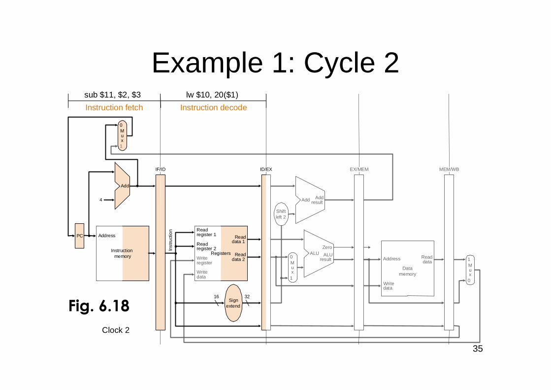
Example 1: Cycle 2
Instructionmemory
Address
4
32
0
Add Addresult
Shiftleft 2
Inst
ruct
ion
IF/ID EX/MEM MEM/WB
Mux
0
1
Add
PC
0Writedata
Mux
1Registers
Readdata 1
Readdata 2
Readregister 1
Readregister 2
16Sign
extend
Writeregister
Writedata
Readdata
1
ALUresult
Mux
ALUZero
ID/EX
Instruction decode
lw $10, 20($1)
Instruction fetch
sub $11, $2, $3
Address
Datamemory
Clock 2
Fig. 6.18
36
Instructionmemory
Address
4
0
Add Addresult
Shiftleft 2
Inst
ruct
ion
IF/ID EX/MEM MEM/WB
Mux
0
1
Add
PC
0Writedata
Mux
1Registers
Readdata 1
Readdata 2
Readregister 1
Readregister 2
Writeregister
Writedata
Readdata
1
ALUresult
Mux
ALUZero
ID/EX
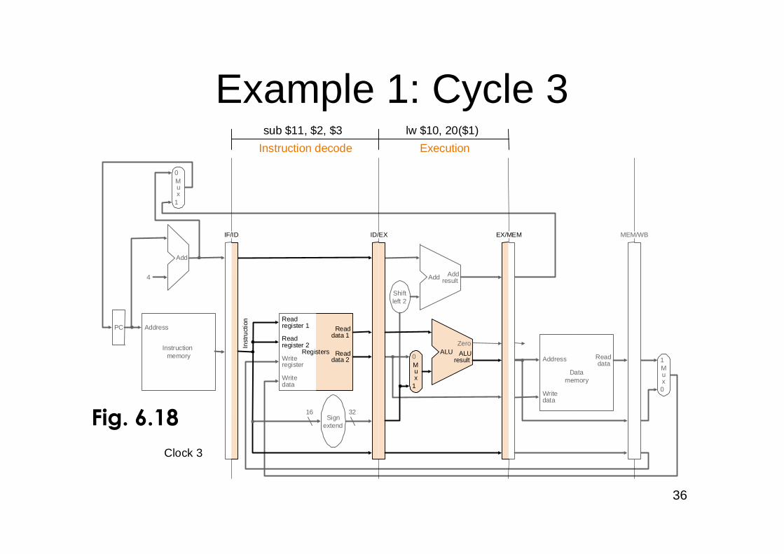
Execution
lw $10, 20($1)
Instruction decode
sub $11, $2, $3
3216Sign
extend
Address
Datamemory
Clock 3
Example 1: Cycle 3
Fig. 6.18
37
Instructionmemory
Address
4
0
Add Addresult
Shiftleft 2
Inst
ruct
ion
IF/ID EX/MEM MEM/WB
Mux
0
1
Add
PC
0Writedata
Mux
1Registers
Readdata 1
Readdata 2
Readregister 1
Readregister 2
3216Sign
extend
Writeregister
Writedata
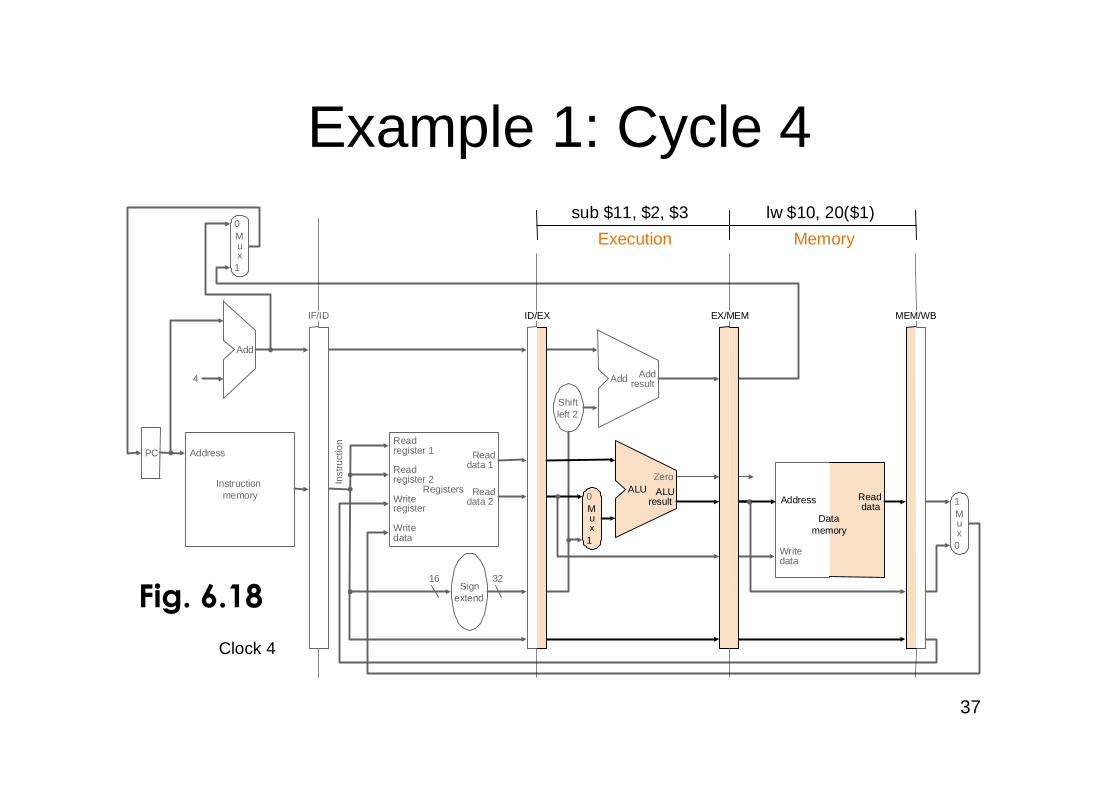
Memory
lw $10, 20($1)
Readdata
1
ALUresult
Mux
ALUZero
ID/EX
Execution
sub $11, $2, $3
Datamemory
Address
Clock 4
Example 1: Cycle 4
Fig. 6.18
38
Instructionmemory
Address
4
32
0
Add Addresult
1
ALUresult
Zero
Shiftleft 2
Inst
ruct
ion
IF/ID EX/MEMID/EX MEM/WB
Write backMux
0
1
Add
PC
0Writedata
Mux
1Registers
Readdata 1
Readdata 2
Readregister 1
Readregister 2
16Sign
extend
Mux
ALUReaddata
Writeregister
Writedata
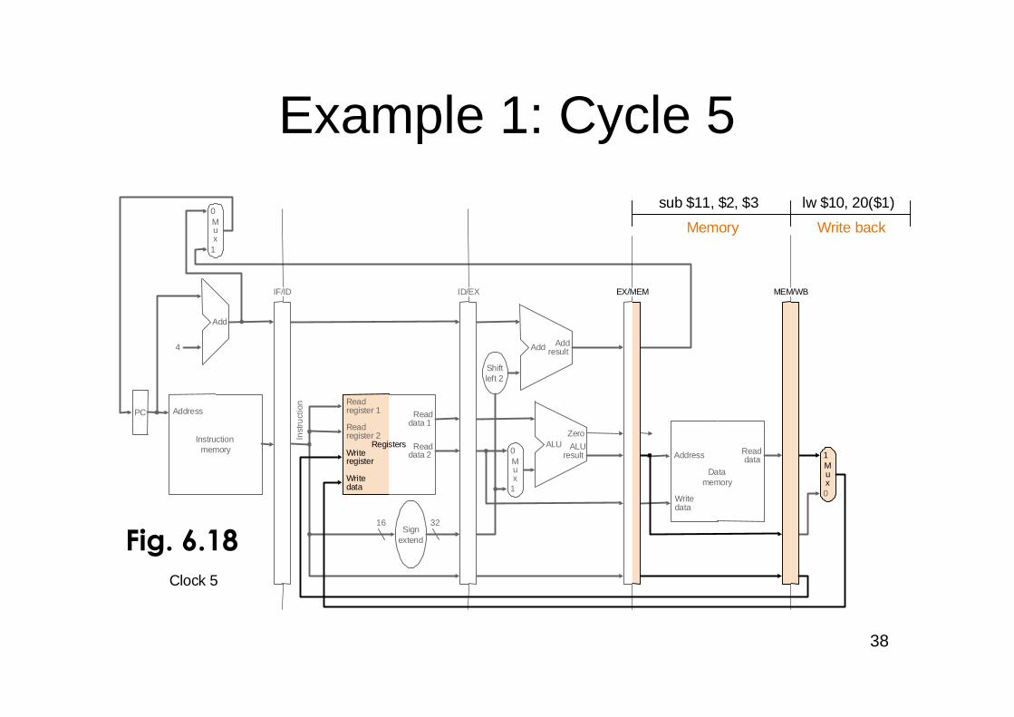
lw $10, 20($1)
Memory
sub $11, $2, $3
Address
Datamemory
Clock 5
Example 1: Cycle 5
Fig. 6.18
39
Instructionmemory
Address
4
32
0
Add Addresult
1
ALUresult
Zero
Shiftleft 2
Inst
ruct
ion
IF/ID EX/MEMID/EX MEM/WB
Write backMux
0
1
Add
PC
0Writedata
Mux
1Registers
Readdata 1
Readdata 2
Readregister 1
Readregister 2
16Sign
extend
Mux
ALUReaddata
Writeregister
Writedata
sub $11, $2, $3
Address
Datamemory
Clock 6
Example 1: Cycle 6
Fig. 6.18
40
OutlineOutline
An overview of pipeliningA pipelined datapathPipelined control (6.3)Data hazards and forwardingData hazards and stallsBranch hazardsExceptionsSuperscalar and dynamic pipelining
41
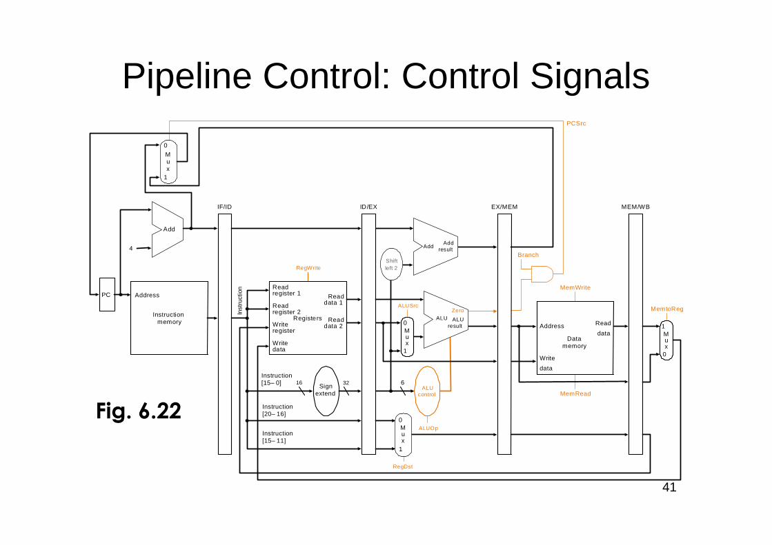
Pipeline Control: Control Signals
PC
Instructionmemory
Address
Inst
ruct
ion
Instruction[20–16]
MemtoReg
ALUOp
Branch
RegDst
ALUSrc
4
16 32Instruction[15–0]
0
0Registers
Writeregister
Writedata
Readdata 1
Readdata 2
Readregister 1
Readregister 2
Signextend
Mux
1Write
data
Read
data Mux
1
ALUcontrol
RegWrite
MemRead
Instruction[15–11]
6
IF/ID ID/EX EX/MEM MEM/WB
MemWrite
Address
Datamemory
PCSrc
Zero
AddAdd
result
Shiftleft 2
ALUresult
ALUZero
Add
0
1
Mux
0
1
Mux
Fig. 6.22
42
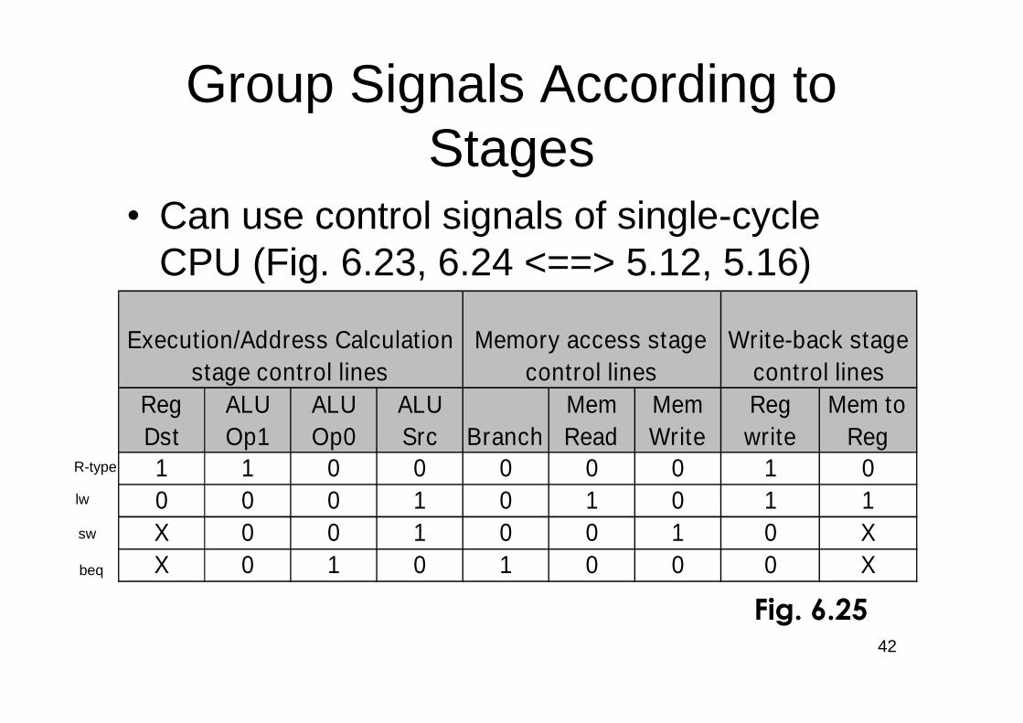
Execution/Address Calculationstage control lines
Memory access stagecontrol lines
Write-back stagecontrol lines
RegDst
ALUOp1
ALUOp0
ALUSrc Branch
MemRead
MemWrite
Regwrite
Mem toReg
1 1 0 0 0 0 0 1 00 0 0 1 0 1 0 1 1X 0 0 1 0 0 1 0 XX 0 1 0 1 0 0 0 X
Fig. 6.25
Group Signals According toStages
•Can use control signals of single-cycleCPU (Fig. 6.23, 6.24 <==> 5.12, 5.16)
R-type
lw
sw
beq
43
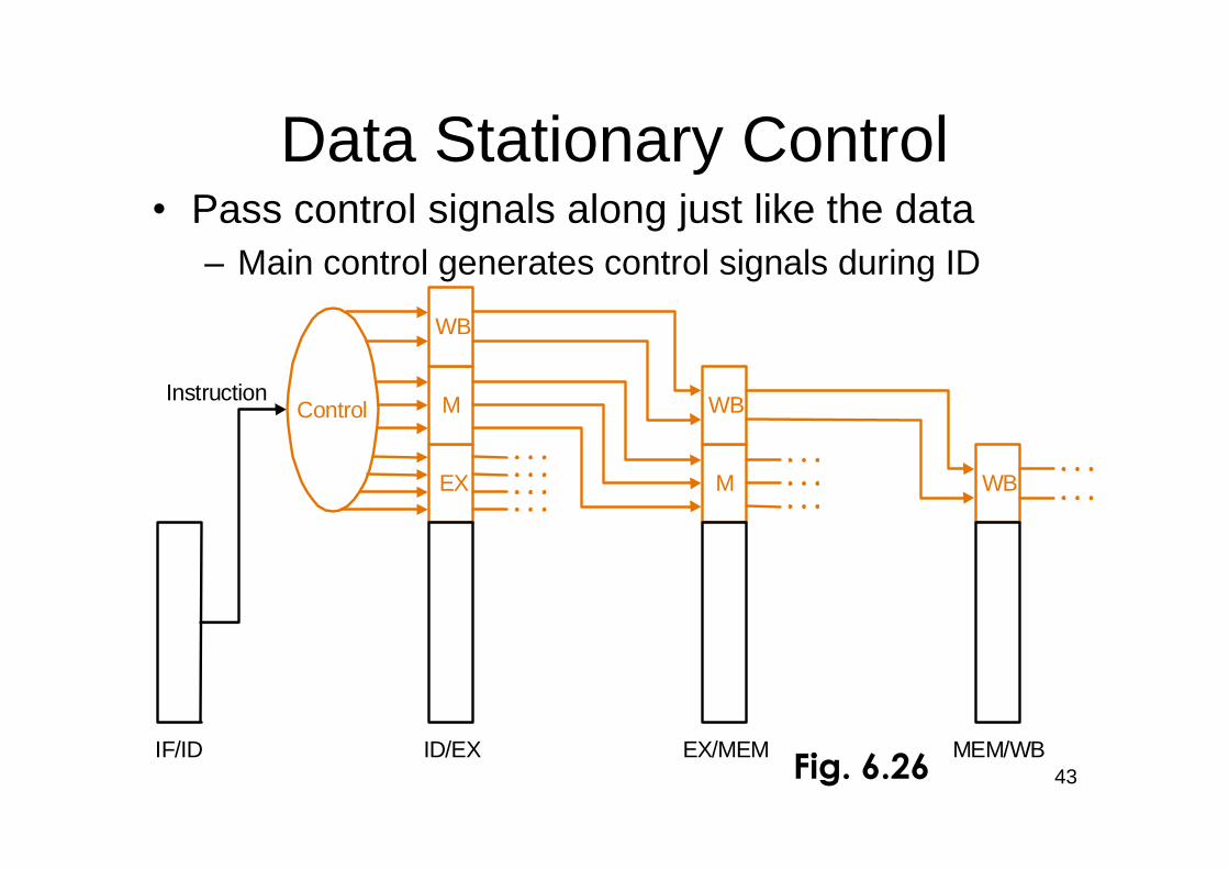
•Pass control signals along just like the data–Main control generates control signals during ID
Data Stationary Control
Control
EX
M
WB
M
WB
WB
IF/ID ID/EX EX/MEM MEM/WB
Instruction
Fig. 6.26
44
IF/ID
Register
ID/E
xR
egister
Ex/M
EM
Register
ME
M/W
BR
egister
ID EX MEM
ExtOp
ALUOp
RegDst
ALUSrc
BranchMemWr
MemtoRegRegWr
MainControl
ExtOp
ALUOp
RegDst
ALUSrc
MemtoRegRegWr
MemtoRegRegWr
MemtoRegRegWr
BranchMemWr Branch
MemW
WB
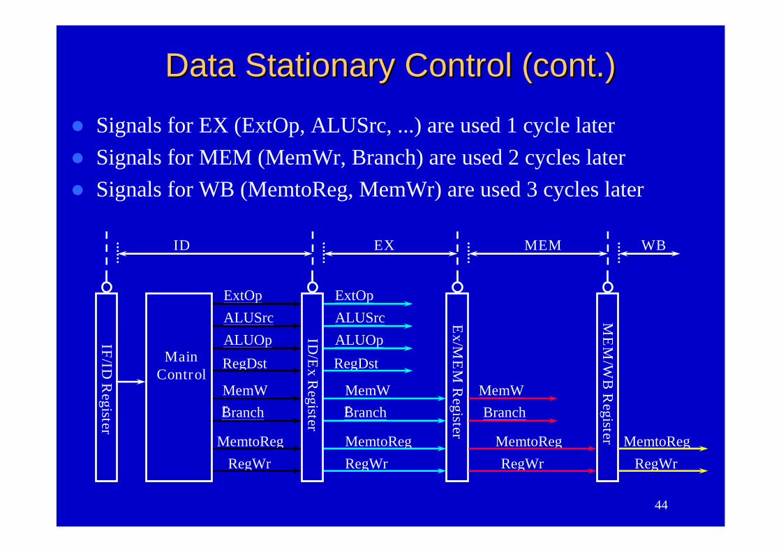
Data Stationary Control (cont.)Data Stationary Control (cont.)
Signals for EX (ExtOp, ALUSrc, ...) are used 1 cycle later Signals for MEM (MemWr, Branch) are used 2 cycles later Signals for WB (MemtoReg, MemWr) are used 3 cycles later

45
WB Stage of load•Reg[IR[20-16]] = MDR
Instructionmemory
Address
4
32
0
Add Addresult
Shiftleft 2
Inst
ruct
ion
IF/ID EX/MEM
Mux
0
1
Add
PC
0Writedata
Mux
1Registers
Readdata 1
Readdata 2
Readregister 1
Readregister 2
16Sign
extend
Writedata
ReaddataData
memory
1
ALUresult
Mux
ALUZero
ID/EX MEM/WB
Write backlw
Writeregister
Address
Fig. 6.14
Who willsupply thisaddress?
46
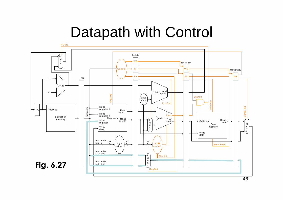
Datapath with Control
PC
Instructionmemory
Inst
ruct
ion
Add
Instruction[20–16]
Mem
toR
eg
ALUOp
Branch
RegDst
ALUSrc
4
16 32Instruction[15–0]
0
0
Mux
0
1
Add Addresult
RegistersW riteregister
W ritedata
Readdata 1
Readdata 2
Readregister 1
Readregister 2
Signextend
Mux
1
ALUresult
Zero
Writedata
Readdata
Mux
1
ALUcontrol
Shiftleft 2
Reg
Writ
e
MemRead
Control
ALU
Instruction[15–11]
6
EX
M
WB
M
WB
WBIF/ID
PCSrc
ID/EX
EX/MEM
MEM/WB
Mux
0
1
Mem
Writ
e
AddressData
memory
Address
Fig. 6.27
47
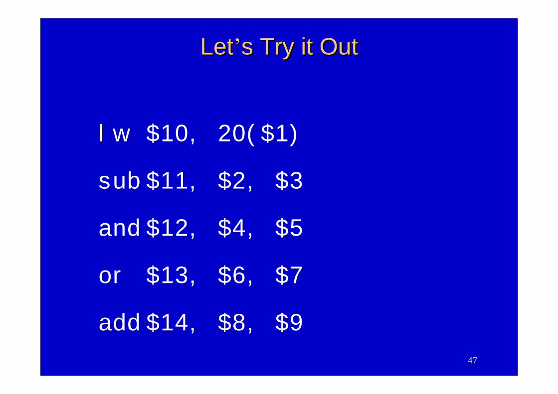
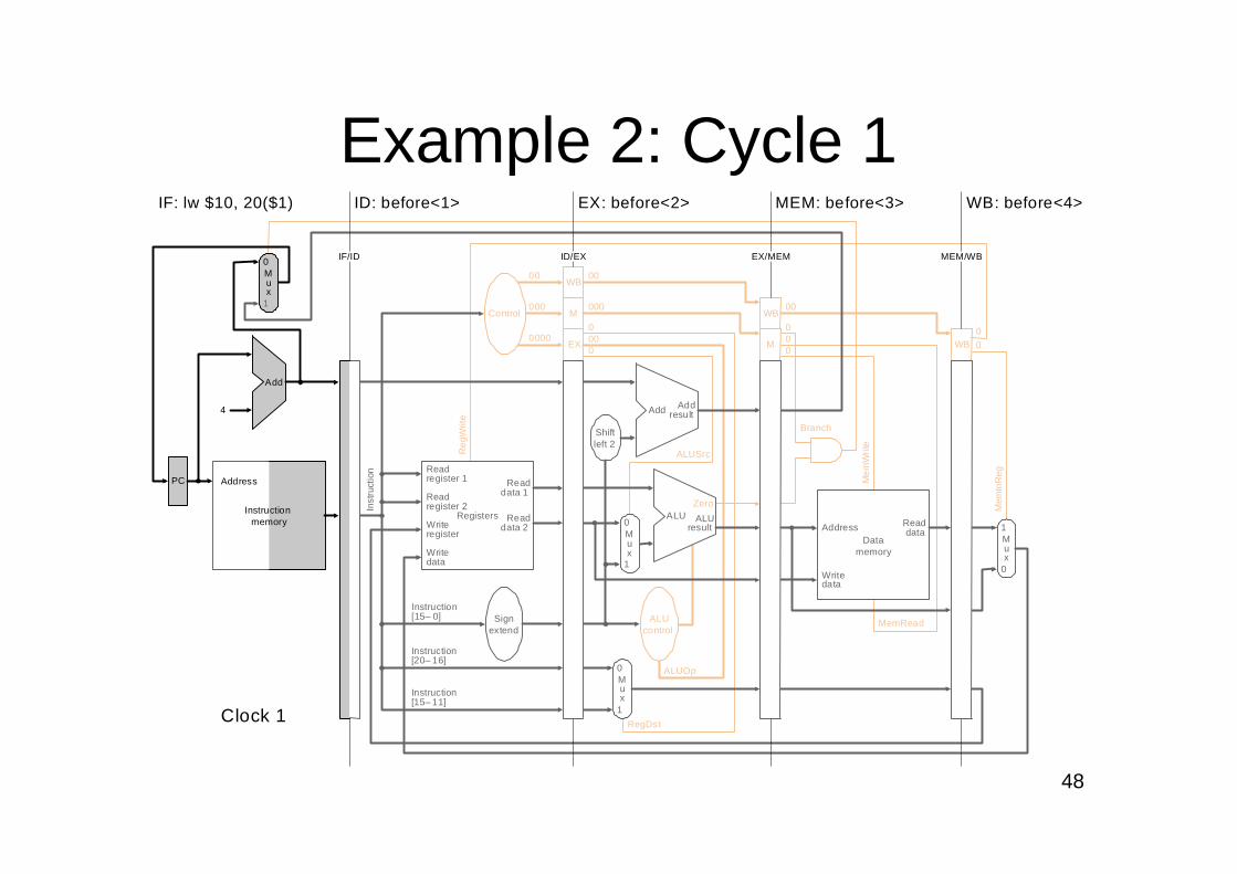
lw $10, 20($1)
sub $11, $2, $3
and $12, $4, $5
or $13, $6, $7
add $14, $8, $9
LetLet’’s Try it Outs Try it Out
48
Example 2: Cycle 1
Instructionmemory
Instruction[20–16]
Mem
toR
eg
ALUOp
Branch
RegDst
ALUSrc
4
Instruction[15–0]
0
Mux
0
1
Add Addresult
RegistersWriteregister
Writedata
Readdata 1
Readdata 2
Readregister 1
Readregister 2
Signextend
Mux
1
ALUresult
Zero
ALUcontrol
Shiftleft 2
Reg
Writ
e
MemRead
Control
ALU
Instruction[15–11]
EX
M
WB
M
WB
WB
Inst
ruct
ion
IF/ID EX/MEMID/EX
ID: before<1> EX: before<2> MEM: before<3> WB: before<4>
MEM/WB
IF: lw $10, 20($1)
000
00
0000
000
00
000
0
00
00
0
00
Mux
0
1
Add
PC
0
Datamemory
Address
Writedata
Readdata
Mux
1
Mem
Writ
e
Address
Clock 1
49
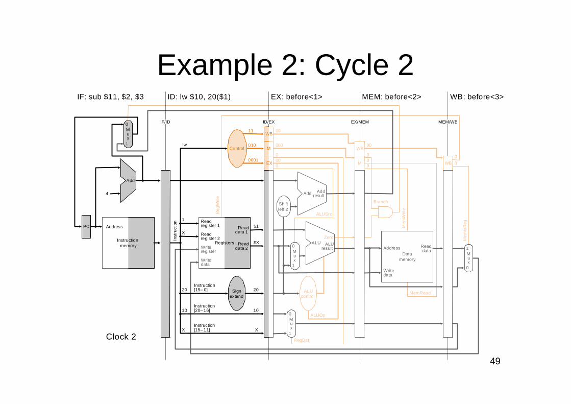
Example 2: Cycle 2
WB
EX
M
Instructionmemory
Mem
toR
eg
ALUOp
Branch
RegDst
ALUSrc
4
0
Mux
0
1
Add Addresult
Writeregister
Writedata
Mux
1
ALUresult
Zero
ALUcontrol
Shiftleft 2
Reg
Writ
e
ALU
M
WB
WB
Inst
ruct
ion
IF/ID EX/MEMID/EX
ID: lw $10, 20($1) EX: before<1> MEM: before<2> WB: before<3>
MEM/WB
IF: sub $11, $2, $3
010
11
0001
000
00
000
0
00
00
0
00
Mux
0
1
Add
PC
0Writedata
Readdata
Mux
1
lwControl
Registers
Readdata 1
Readdata 2
Readregister 1
Readregister 2
X
10
20
X
1
Instruction[20–16]
Instruction[15–0] Sign
extend
Instruction[15–11]
20
$X
$1
10
X
MemRead
Mem
Writ
e
Datamemory
Address
Address
Clock 2
50
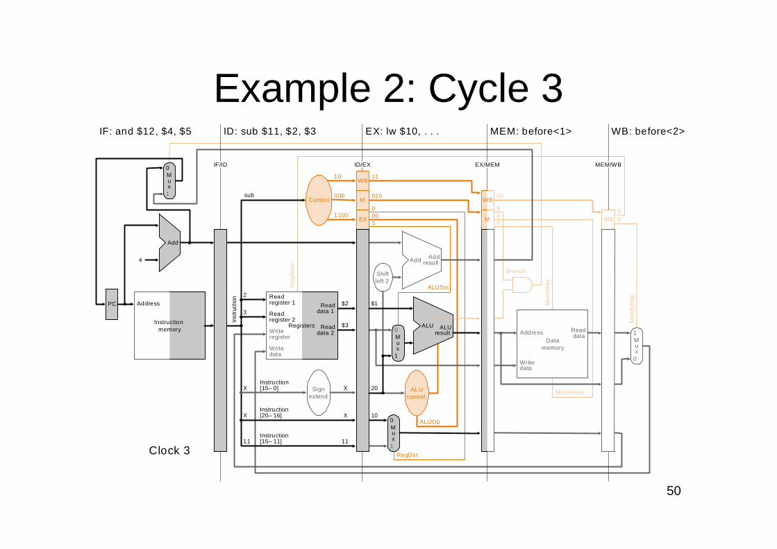
Instructionmemory
Address
Instruction[20–16]
Mem
toR
eg
Branch
ALUSrc
4
Instruction[15–0]
0
1
Add Addresult
RegistersWriteregister
Writedata
Readdata 1
Readdata 2
Readregister 1
Readregister 2
ALUresult
Shiftleft 2
Reg
Writ
e
MemRead
Control
ALU
Instruction[15–11]
EX
M
WB
WB
Inst
ruct
ion
IF/ID EX/MEMID/EX
ID: sub $11, $2, $3 EX: lw $10, . . . MEM: before<1> WB: before<2>
MEM/WB
IF: and $12, $4, $5
000
10
1100
010
11
000
1
00
00
0
00
Mux
0
1
Add
PC
0Writedata
Readdata
Mux
1
Mem
Writ
e
sub
11
X
X
3
2
X
$3
$2
X
11
$1
20
10
Mux
0
Mux
1
ALUOp
RegDst
ALUcontrol
M
WB
Zero
Signextend
Datamemory
Address
Clock 3
Example 2: Cycle 3
51
WB
EX
M
Instructionmemory
Address
Mem
toR
eg
ALUOp
Branch
RegDst
ALUSrc
4
0
0
1
Add Addresult
Writeregister
Writedata 1
ALUresult
ALUcontrol
Shiftleft 2
Reg
Writ
e
M
WB
Inst
ruct
ion
IF/ID EX/MEMID/EX
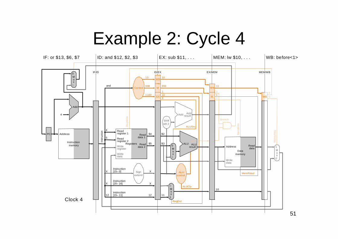
ID: and $12, $2, $3 EX: sub $11, . . . MEM: lw $10, . . . WB: before<1>
MEM/WB
IF: or $13, $6, $7
000
10
1100
000
10
101
0
11
10
0
00
Mux
0
1
Add
PC
0Writedata
Mux
1
andControl
Registers
Readdata 1
Readdata 2
Readregister 1
Readregister 2
12
X
X
5
4
Instruction[20–16]
Instruction[15–0]
Instruction[15–11]
X
$5
$4
X
12
MemRead
Mem
Writ
e
$3
$2
11
Mux
Mux
ALUAddress Read
dataData
memory
10
WB
Zero
Signextend
Clock 4
Example 2: Cycle 4
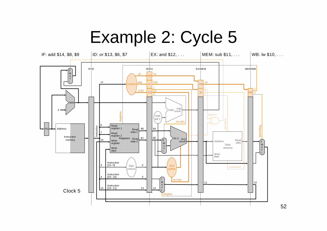
52
Example 2: Cycle 5
Instructionmemory
Address
Instruction[20–16]
Branch
ALUSrc
4
Instruction[15–0]
0
1
Add Addresult
RegistersWriteregister
Writedata
Readdata 1
Readdata 2
Readregister 1
Readregister 2
ALUresult
Shiftleft 2
Reg
Writ
e
MemRead
Control
ALU
Instruction[15–11]
EX
M
WB
Inst
ruct
ion
IF/ID EX/MEMID/EX
ID: or $13, $6, $7 EX: and $12, . . . MEM: sub $11, . . . WB: lw $10, . . .
MEM/WB
IF: add $14, $8, $9
000
10
1100
000
10
101
0
10
00
0
Mux
0
1
Add
PC
0Writedata
Readdata
Mux
1
Mem
Writ
e
or
13
X
X
7
6
X
$7
$6
X
13
$4
Mux
0
Mux
1
ALUOp
RegDst
ALUcontrol
M
WB
11 10
10$5
12
WB
Mem
toR
eg
11
Zero
Datamemory
Address
Signextend
Clock 5
53
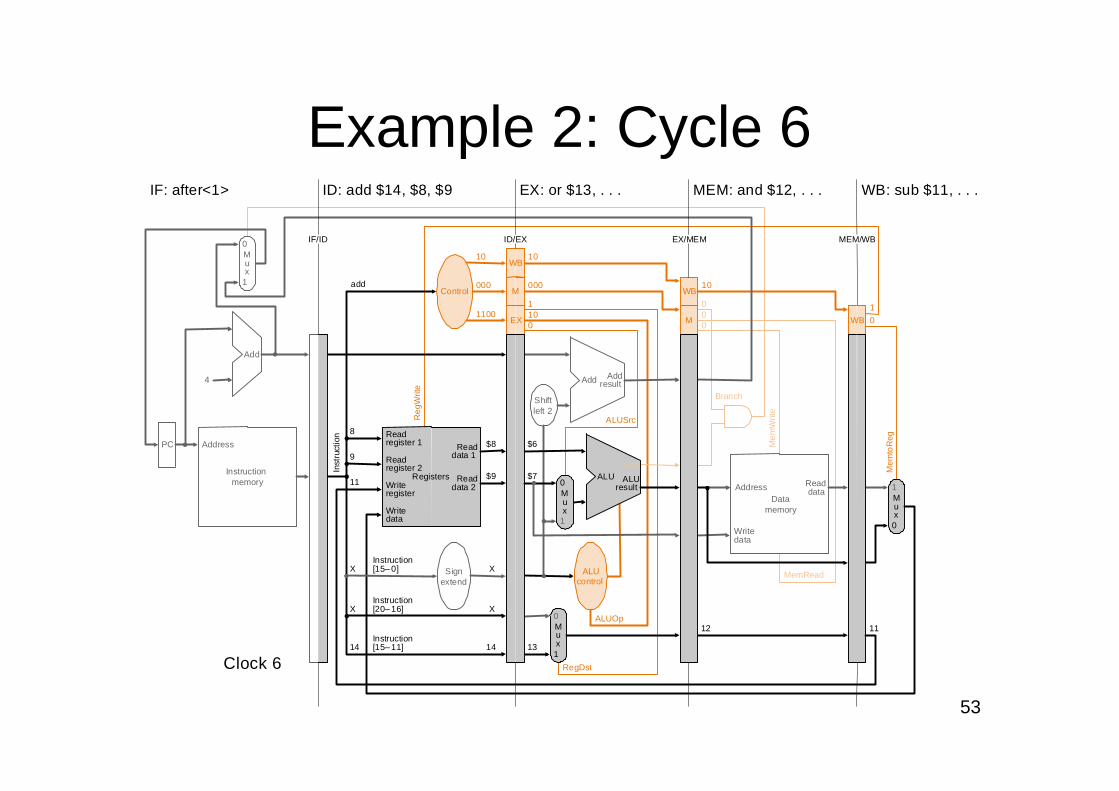
Example 2: Cycle 6
WB
EX
M
Instructionmemory
Address
Mem
toR
eg
ALUOp
Branch
RegDst
ALUSrc
4
0
0
1
Add Addresult
1
ALUresult
ALUcontrol
Shiftleft 2
Reg
Writ
e
M
WB
Inst
ruct
ion
IF/ID EX/MEMID/EX
ID: add $14, $8, $9 EX: or $13, . . . MEM: and $12, . . . WB: sub $11, . . .
MEM/WB
IF: after<1>
000
10
1100
000
10
101
0
10
00
0
10
Mux
0
1
Add
PC
0Writedata
Mux
1
addControl
Registers
Readdata 1
Readdata 2
Readregister 1
Readregister 2
14
X
X
9
8
Instruction[20–16]
Instruction[15–0]
Instruction[15–11]
X
$9
$8
X
14
MemRead
Mem
Writ
e
$7
$6
13
Mux
Mux
ALUReaddata
12
WB
11
11
Writeregister
Writedata
Zero
Datamemory
Address
Signextend
Clock 6
54
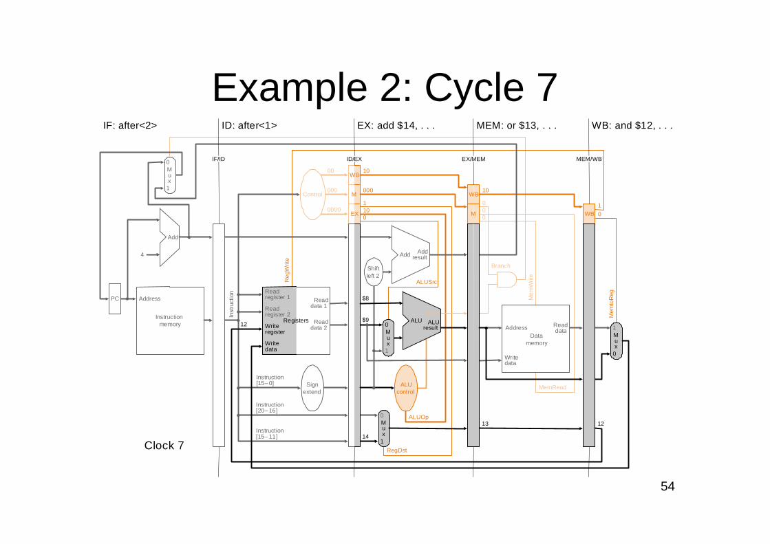
Example 2: Cycle 7
Fig. 6.34
Instructionmemory
Address
Instruction[20–16]
Branch
ALUSrc
4
Instruction[15–0]
0
1
Add Addresult
RegistersWriteregister
Writedata
ALUresult
Shiftleft 2
Reg
Writ
e
MemRead
Control
ALU
Instruction[15–11]
Signextend
EX
M
WB
Inst
ruct
ion
IF/ID EX/MEMID/EX
ID: after<1> EX: add $14, . . . MEM: or $13, . . . WB: and $12, . . .
MEM/WB
IF: after<2>
000
00
0000
000
10
101
0
10
00
0
Mux
0
1
Add
PC
0Writedata
Readdata
Mux
1
Mem
Writ
e
$8
Mux
0
Mux
1
ALUOp
RegDst
ALUcontrol
M
WB
13 12
12$9
14
WB
Mem
toR
eg
10
Readdata 1
Readdata 2
Readregister 1
Readregister 2 Zero
Datamemory
Address
Clock 7
55
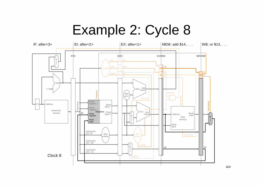
Example 2: Cycle 8
Fig. 6.34
WB
EX
M
Instructionmemory
Address
Mem
toR
eg
ALUOp
Branch
RegDst
ALUSrc
4
0
0
1
Add Addresult
1
ALUresult
Zero
ALUcontrol
Shiftleft 2
Reg
Writ
e
M
WB
Inst
ruct
ion
IF/ID EX/MEMID/EX
ID: after<2> EX: after<1> MEM: add $14, . . . WB: or $13, . . .
MEM/WB
IF: after<3>
000
00
0000
000
00
000
0
10
00
0
10
Mux
0
1
Add
PC
0Writedata
Mux
1
Control
Registers
Readdata 1
Readdata 2
Readregister 1
Readregister 2
Instruction[20–16]
Instruction[15–0] Sign
extend
Instruction[15–11]
MemRead
Mem
Writ
e
Mux
Mux
ALUReaddata
14
WB
13
13
Writeregister
Writedata
Datamemory
Address
Clock 8
56
WB
EX
M
Instructionmemory
Address
Mem
toR
eg
ALUOp
Branch
RegDst
ALUSrc
4
0
0
1
Add Addresult
1
ALUresult
Zero
ALUcontrol
Shiftleft 2
Reg
Writ
e
M
WB
Inst
ruct
ion
IF/ID EX/MEMID/EX
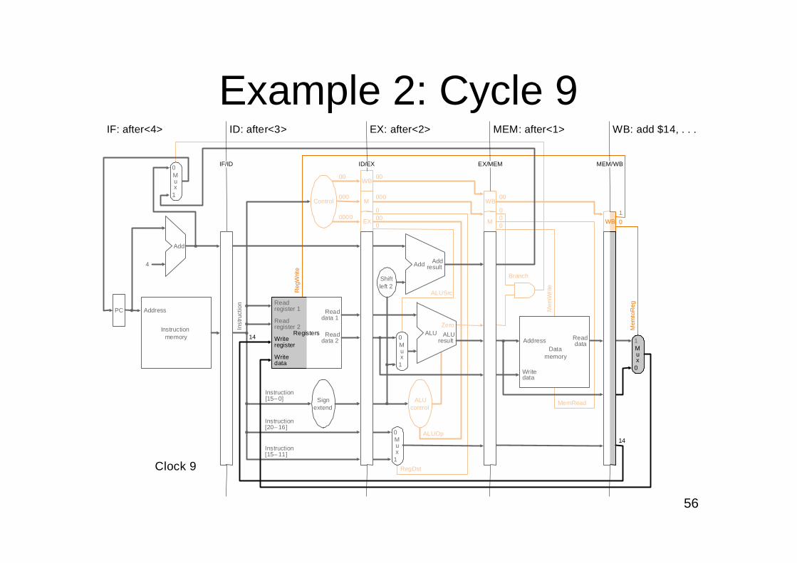
ID: after<3> EX: after<2> MEM: after<1> WB: add $14, . . .
MEM/WB
IF: after<4>
000
00
0000
000
00
000
0
00
00
0
10
Mux
0
1
Add
PC
0Writedata
Mux
1
Control
Registers
Readdata 1
Readdata 2
Readregister 1
Readregister 2
Instruction[20–16]
Instruction[15–0] Sign
extend
Instruction[15–11]
MemRead
Mem
Writ
e
Mux
Mux
ALUReaddata
WB
14
14
Writeregister
Writedata
Datamemory
Address
Clock 9
Example 2: Cycle 9
57
Summary of Pipeline BasicsSummary of Pipeline Basics
Pipelining is a fundamental concept–Multiple steps using distinct resources–Utilize capabilities of datapath by pipelined instruction
processing Start next instrunction while working on the current one Limited by length of longest stage (plus fill/flush) Need to detect and resolve hazards
What makes it easy in MIPS?–All instructions are of the same length–Just a few instruction formats–Memory operands only in loads and stores
What makes pipelining hard? hazards
58
OutlineOutline
An overview of pipeliningA pipelined datapathPipelined controlData hazards and forwarding (6.4)Data hazards and stalls (6.5)Branch hazardsExceptionsSuperscalar and dynamic pipelining
59
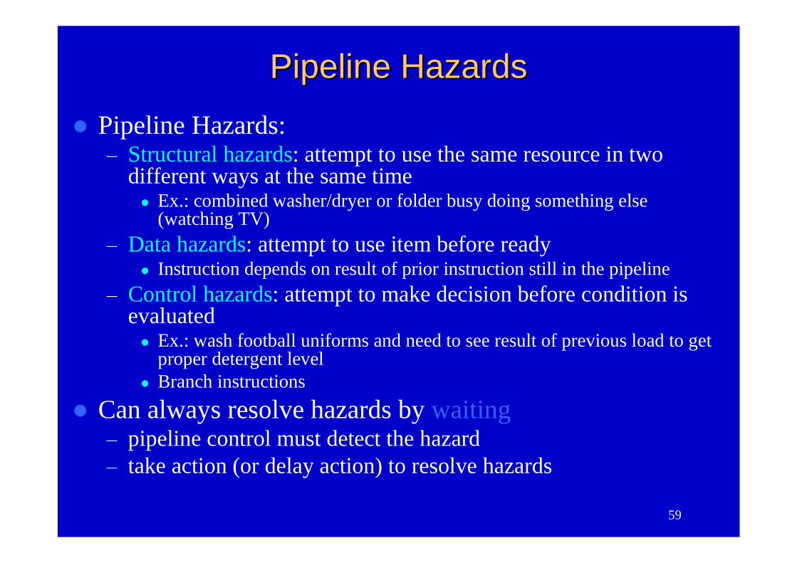
Pipeline HazardsPipeline Hazards
Pipeline Hazards:–Structural hazards: attempt to use the same resource in two
different ways at the same time Ex.: combined washer/dryer or folder busy doing something else
(watching TV)–Data hazards: attempt to use item before ready
Instruction depends on result of prior instruction still in the pipeline–Control hazards: attempt to make decision before condition is
evaluated Ex.: wash football uniforms and need to see result of previous load to get
proper detergent level Branch instructions
Can always resolve hazards by waiting–pipeline control must detect the hazard–take action (or delay action) to resolve hazards
60
Mem
Instr.
Order
Time
Load
Instr 1
Instr 2
Instr 3
Instr 4A
LUMem Reg Mem Reg
AL
UMem Reg Mem Reg
AL
UMem Reg Mem RegA
LUReg Mem Reg
AL
UMem Reg Mem Reg
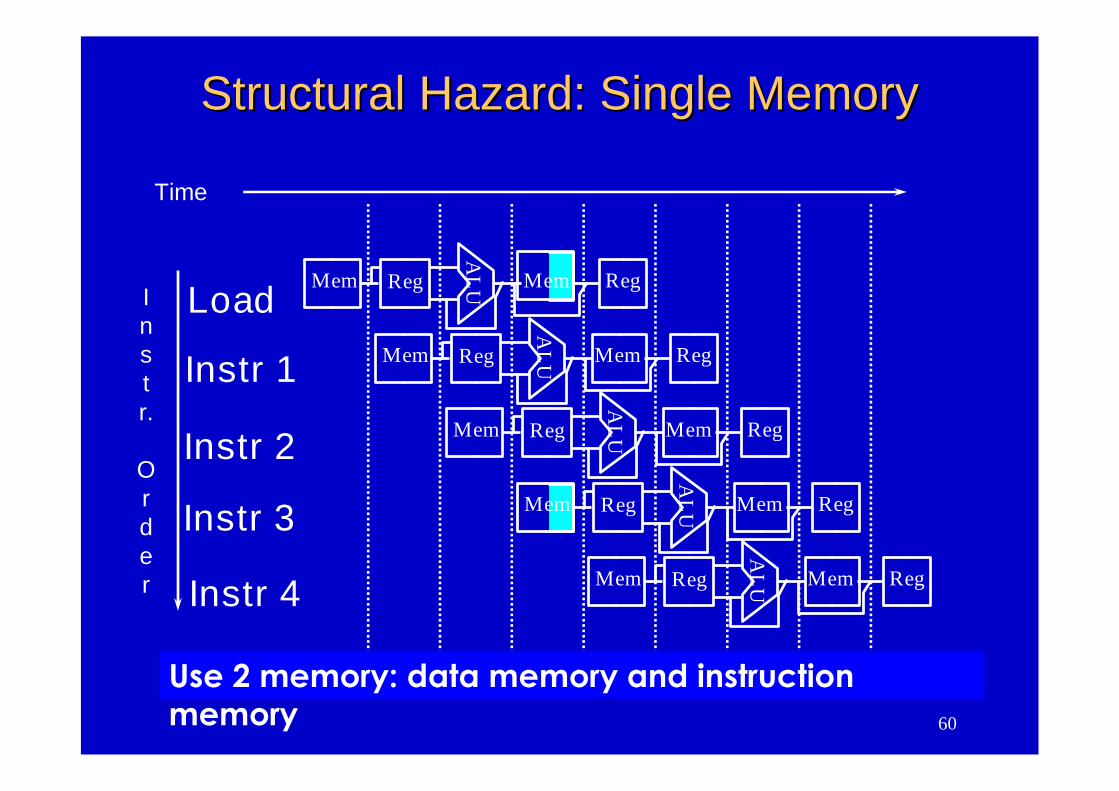
Use 2 memory: data memory and instructionmemory
Structural Hazard: Single MemoryStructural Hazard: Single Memory
61
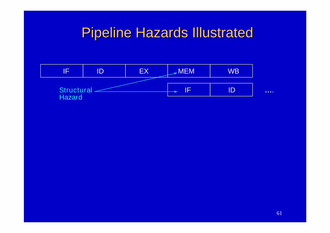
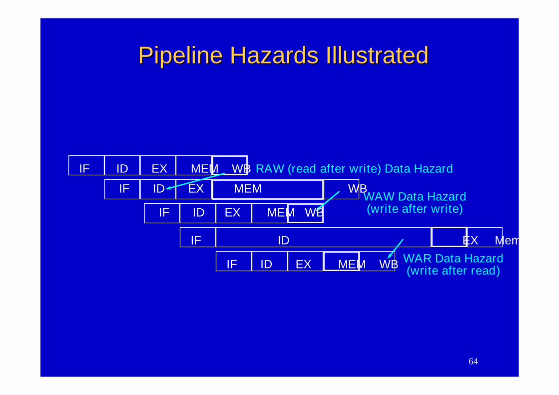
Pipeline Hazards IllustratedPipeline Hazards Illustrated
IF ID EX MEM WB
StructuralHazard
IF ID ….
62
Data Hazards
IM Reg
IM Reg
CC 1 CC 2 CC 3 CC 4 CC 5 CC 6
Time (in clock cycles)
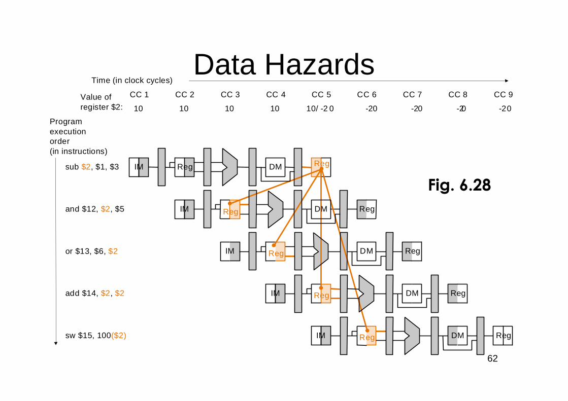
sub $2, $1, $3
Programexecutionorder(in instructions)
and $12, $2, $5
IM Reg DM Reg
IM DM Reg
IM DM Reg
CC 7 CC 8 CC 9
10 10 10 10 10/ -2 0 -20 -20 -20 -20
or $13, $6, $2
add $14, $2, $2
sw $15, 100($2)
Value ofregister $2:
DM Reg
Reg
Reg
Reg
DM
Fig. 6.28
63
Types of Data HazardsTypes of Data Hazards
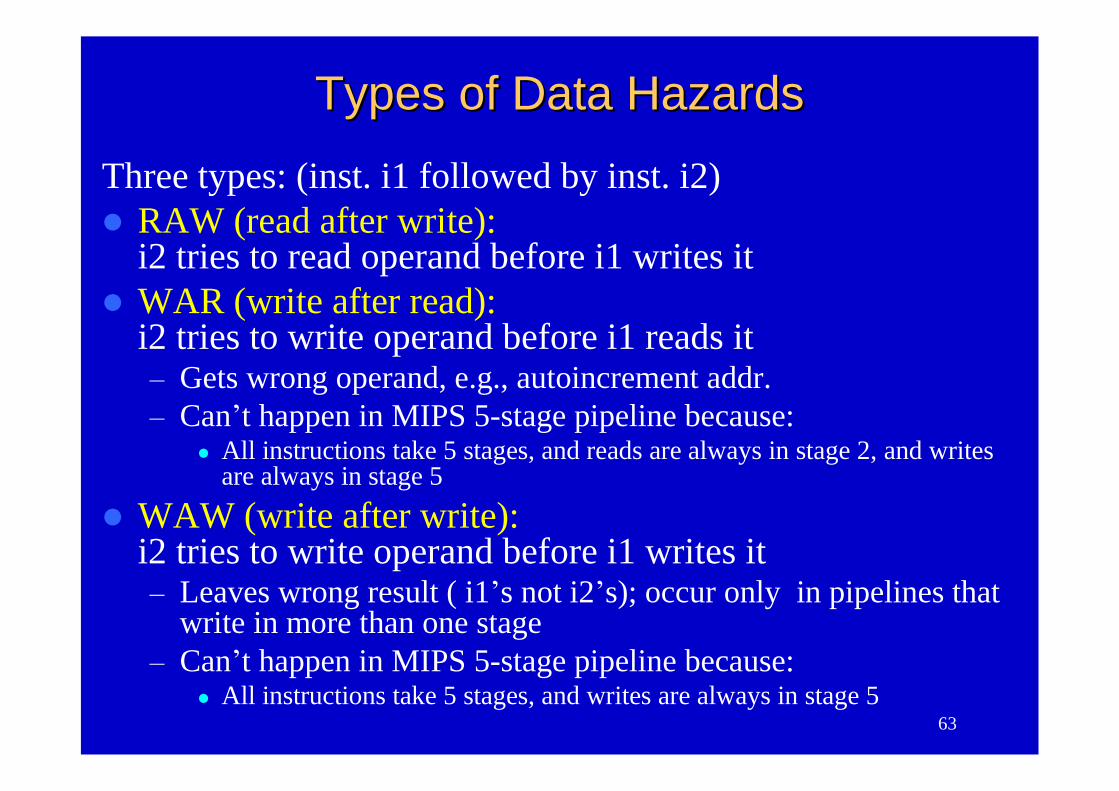
Three types: (inst. i1 followed by inst. i2)RAW (read after write):
i2 tries to read operand before i1 writes itWAR (write after read):
i2 tries to write operand before i1 reads it–Gets wrong operand, e.g., autoincrement addr.–Can’t happen in MIPS 5-stage pipeline because:
All instructions take 5 stages, and reads are always in stage 2, and writesare always in stage 5
WAW (write after write):i2 tries to write operand before i1 writes it–Leaves wrong result ( i1’s not i2’s); occur only in pipelines that
write in more than one stage–Can’t happen in MIPS 5-stage pipeline because:
All instructions take 5 stages, and writes are always in stage 5
64
Pipeline Hazards IllustratedPipeline Hazards Illustrated
IF ID EX MEM WB
IF ID EX Mem
RAW (read after write) Data Hazard
WAW Data Hazard(write after write)
IF ID EX MEM WB WAR Data Hazard(write after read)
IF ID EX MEM WB
IF ID EX MEM WB
65
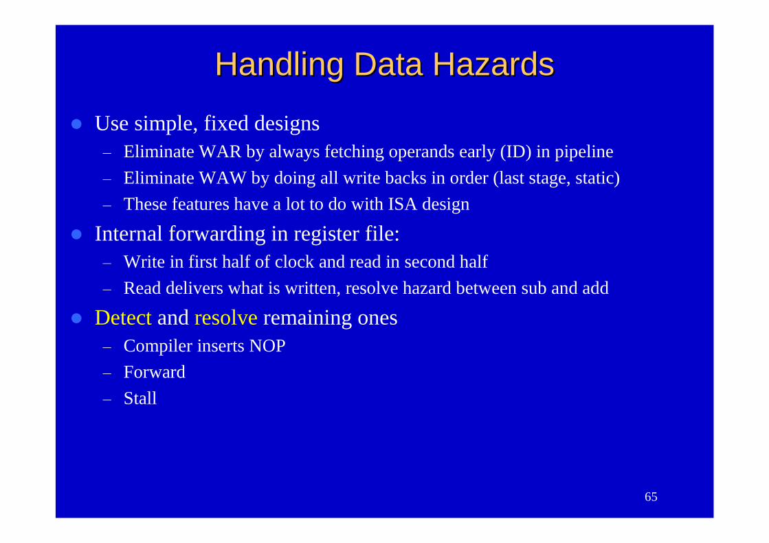
Handling Data HazardsHandling Data Hazards
Use simple, fixed designs– Eliminate WAR by always fetching operands early (ID) in pipeline– Eliminate WAW by doing all write backs in order (last stage, static)– These features have a lot to do with ISA design
Internal forwarding in register file:– Write in first half of clock and read in second half– Read delivers what is written, resolve hazard between sub and add
Detect and resolve remaining ones– Compiler inserts NOP– Forward– Stall
66
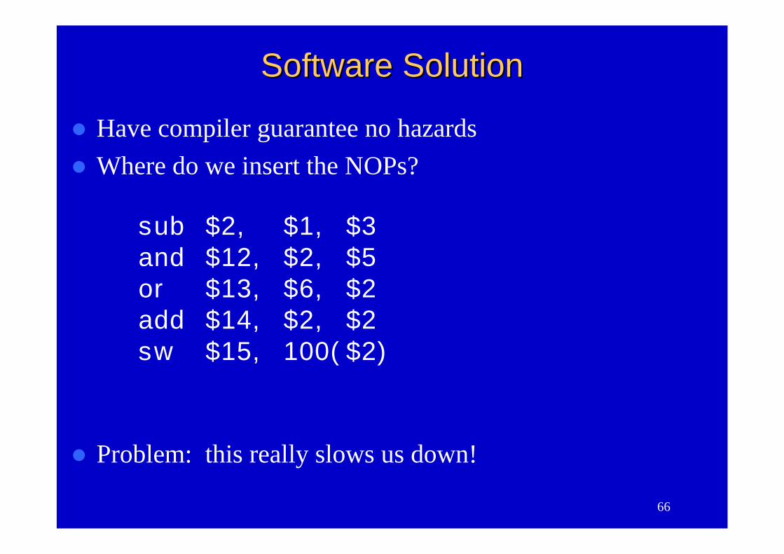
Software SolutionSoftware Solution
Have compiler guarantee no hazardsWhere do we insert the NOPs?
sub $2, $1, $3and $12, $2, $5or $13, $6, $2add $14, $2, $2sw $15, 100($2)
Problem: this really slows us down!
67
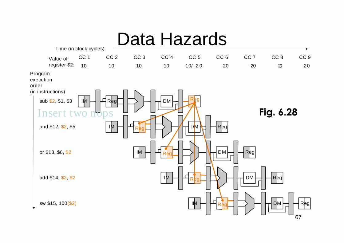
Data Hazards
IM Reg
IM Reg
CC 1 CC 2 CC 3 CC 4 CC 5 CC 6
Time (in clock cycles)
sub $2, $1, $3
Programexecutionorder(in instructions)
and $12, $2, $5
IM Reg DM Reg
IM DM Reg
IM DM Reg
CC 7 CC 8 CC 9
10 10 10 10 10/ -2 0 -20 -20 -20 -20
or $13, $6, $2
add $14, $2, $2
sw $15, 100($2)
Value ofregister $2:
DM Reg
Reg
Reg
Reg
DM
Fig. 6.28Insert two nops
68
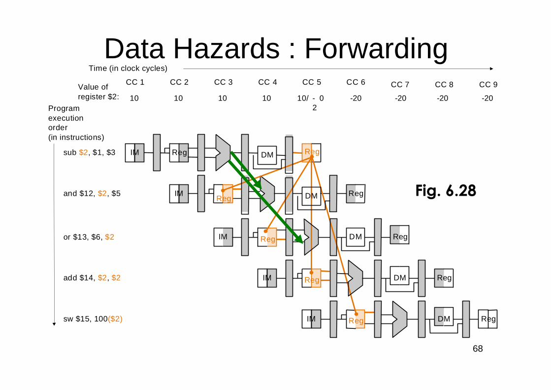
Data Hazards : Forwarding
IM Reg
IM Reg
CC 1 CC 2 CC 3 CC 4 CC 5 CC 6
Time (in clock cycles)
sub $2, $1, $3
Programexecutionorder(in instructions)
and $12, $2, $5
IM Reg DM Reg
IM DM Reg
IM DM Reg
CC 7 CC 8 CC 9
10 10 10 10 10/ -2
0 -20 -20 -20 -20
or $13, $6, $2
add $14, $2, $2
sw $15, 100($2)
Value ofregister $2:
DM Reg
Reg
Reg
Reg
DM Fig. 6.28

69
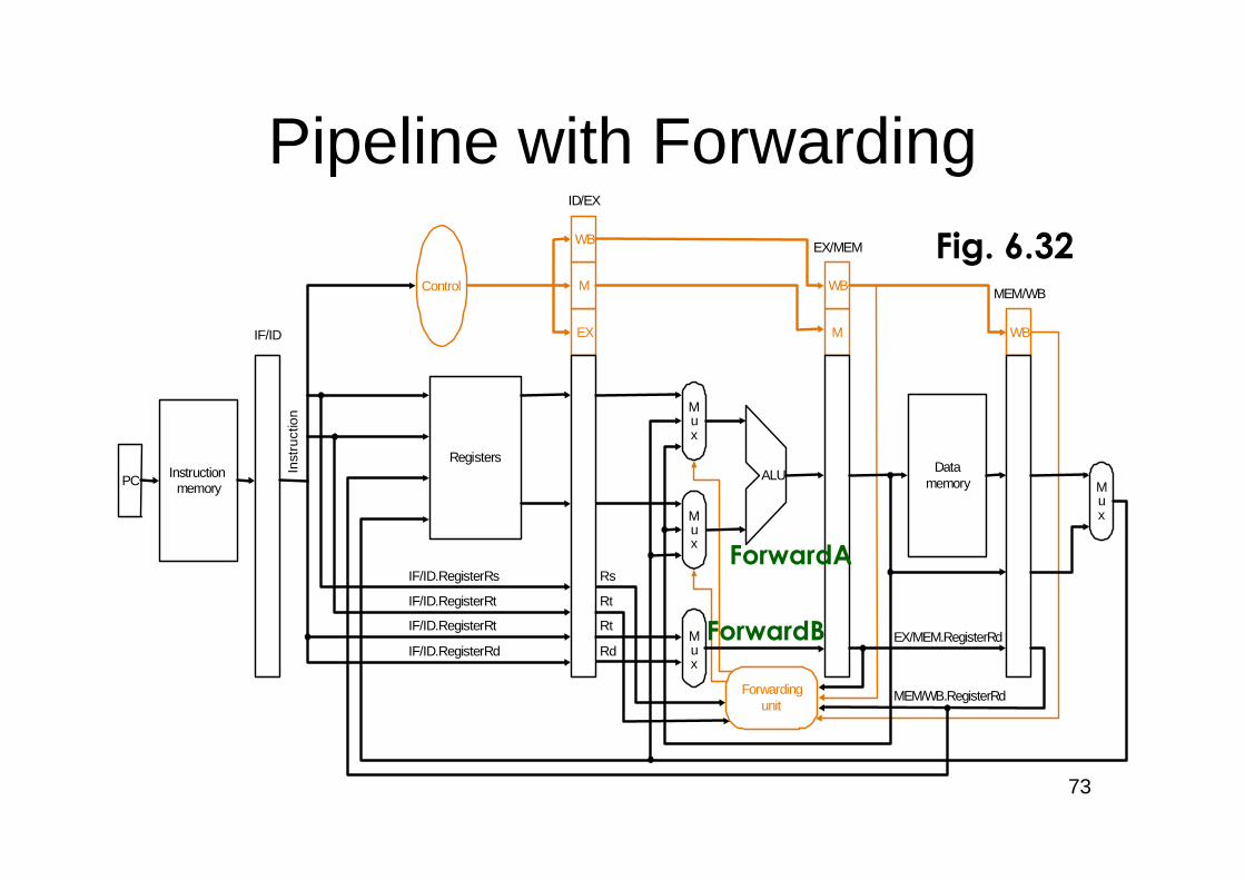
Pipeline with Forwarding
PC Instructionmemory
Registers
Mux
Mux
Control
ALU
EX
M
WB
M
WB
WB
ID/EX
EX/MEM
MEM/WB
Datamemory
Mux
Forwardingunit
IF/ID
Inst
ruct
ion
Mux
RdEX/MEM.RegisterRd
MEM/WB.RegisterRd
Rt
Rt
Rs
IF/ID.RegisterRd
IF/ID.RegisterRt
IF/ID.RegisterRt
IF/ID.RegisterRs
Fig. 6.32
ForwardA
ForwardB
70
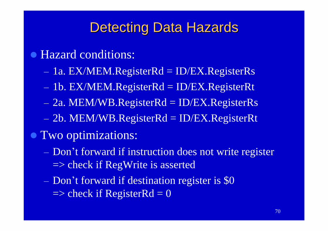
Detecting Data HazardsDetecting Data Hazards
Hazard conditions:–1a. EX/MEM.RegisterRd = ID/EX.RegisterRs–1b. EX/MEM.RegisterRd = ID/EX.RegisterRt–2a. MEM/WB.RegisterRd = ID/EX.RegisterRs–2b. MEM/WB.RegisterRd = ID/EX.RegisterRt
Two optimizations:–Don’t forward if instruction does not write register
=> check if RegWrite is asserted–Don’t forward if destination register is $0
=> check if RegisterRd = 0
71
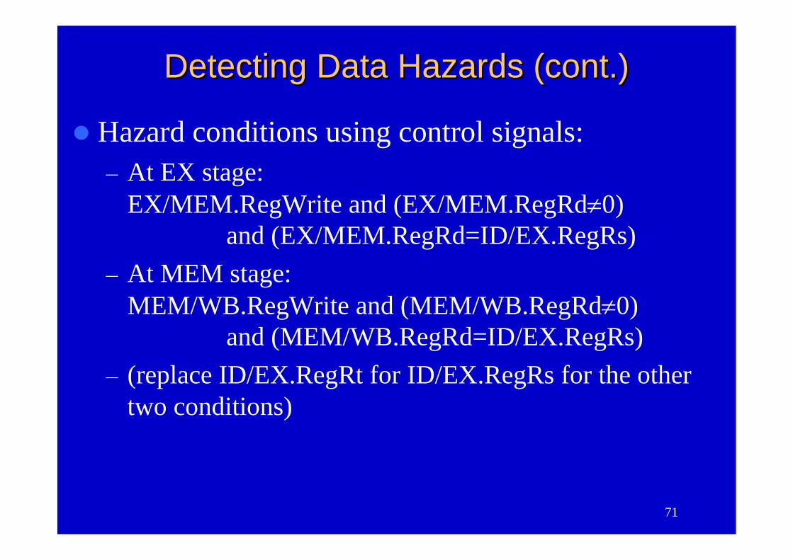
Detecting Data Hazards (cont.)Detecting Data Hazards (cont.)
Hazard conditions using control signals:–At EX stage:
EX/MEM.RegWrite and (EX/MEM.RegRd0)and (EX/MEM.RegRd=ID/EX.RegRs)
–At MEM stage:MEM/WB.RegWrite and (MEM/WB.RegRd0)
and (MEM/WB.RegRd=ID/EX.RegRs)–(replace ID/EX.RegRt for ID/EX.RegRs for the other
two conditions)
72
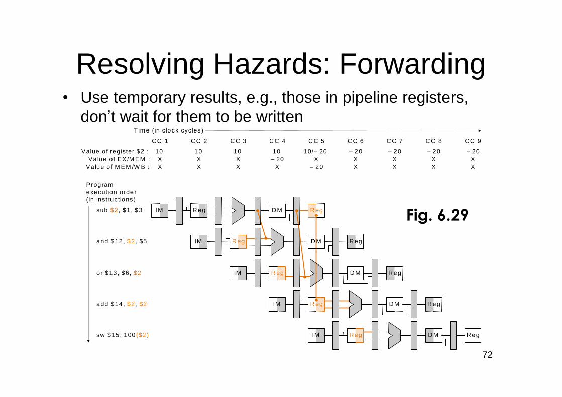
•Use temporary results, e.g., those in pipeline registers,don’t wait for them to be written
Resolving Hazards: Forwarding
IM R eg
IM Reg
CC 1 C C 2 C C 3 C C 4 C C 5 C C 6
Time (in c lock cyc les)
sub $2, $1 , $3
Programexecution orde r(in instruc tions)
and $12 , $2, $5
IM R eg D M R eg
IM DM R eg
IM D M Re g
C C 7 C C 8 C C 9
10 10 10 10 10/–20 –2 0 –20 –20 –20
or $13 , $6, $2
add $14 , $2, $2
sw $15 , 100($2)
Value o f register $2 :
DM R eg
Reg
Reg
R eg
X X X –20 X X X X XVa lue of EX/M EM :X X X X –20 X X X XVa lue o f M EM /W B :
D M
Fig. 6.29
73
Pipeline with Forwarding
PC Instructionmemory
Registers
Mux
Mux
Control
ALU
EX
M
WB
M
WB
WB
ID/EX
EX/MEM
MEM/WB
Datamemory
Mux
Forwardingunit
IF/ID
Inst
ruct
ion
Mux
RdEX/MEM.RegisterRd
MEM/WB.RegisterRd
Rt
Rt
Rs
IF/ID.RegisterRd
IF/ID.RegisterRt
IF/ID.RegisterRt
IF/ID.RegisterRs
Fig. 6.32
ForwardA
ForwardB
74
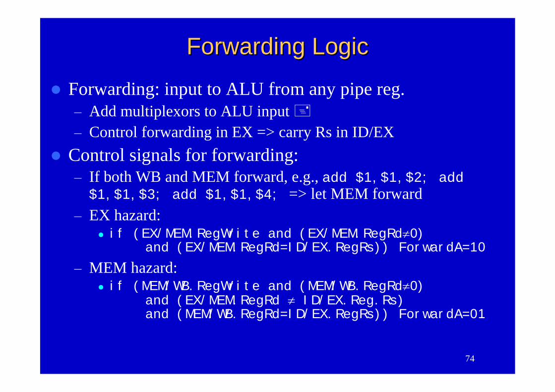
Forwarding LogicForwarding Logic
Forwarding: input to ALU from any pipe reg.–Add multiplexors to ALU input–Control forwarding in EX => carry Rs in ID/EX
Control signals for forwarding:–If both WB and MEM forward, e.g., add $1,$1,$2; add$1,$1,$3; add $1,$1,$4; => let MEM forward
–EX hazard: if (EX/MEM.RegWrite and (EX/MEM.RegRd0)
and (EX/MEM.RegRd=ID/EX.RegRs)) ForwardA=10–MEM hazard:
if (MEM/WB.RegWrite and (MEM/WB.RegRd0)and (EX/MEM.RegRd ID/EX.Reg.Rs)and (MEM/WB.RegRd=ID/EX.RegRs)) ForwardA=01
75
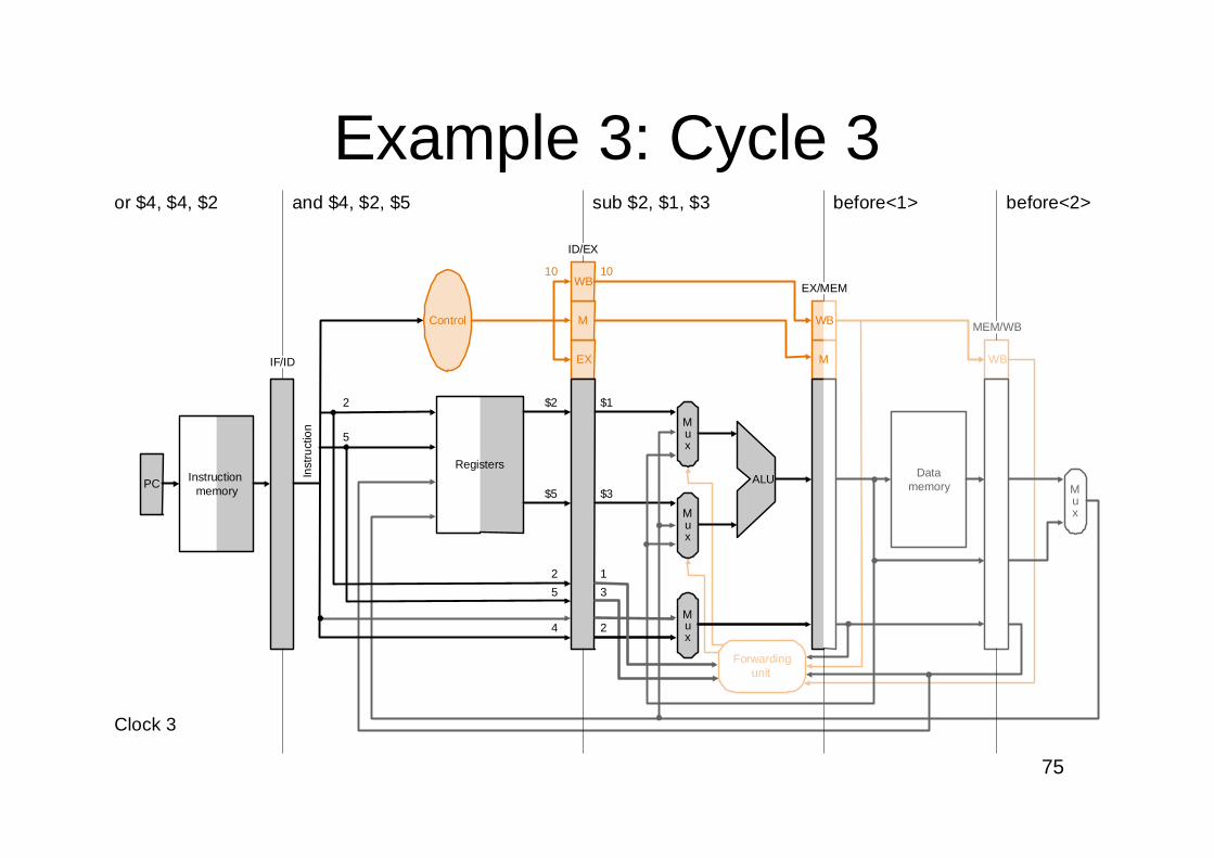
Example 3: Cycle 3
PC Instructionmemory
Registers
Mux
Mux
Mux
EX
M
WB
WB
Datamemory
Mux
Forwardingunit
Inst
ruct
ion
IF/ID
and $4, $2, $5 sub $2, $1, $3
ID/EX
before<1>
EX/MEM
before<2>
MEM/WB
or $4, $4, $2
Clock 3
2
5
10 10
$2
$5
5
2
4
$1
$3
3
1
2
Control
ALU
M
WB
76
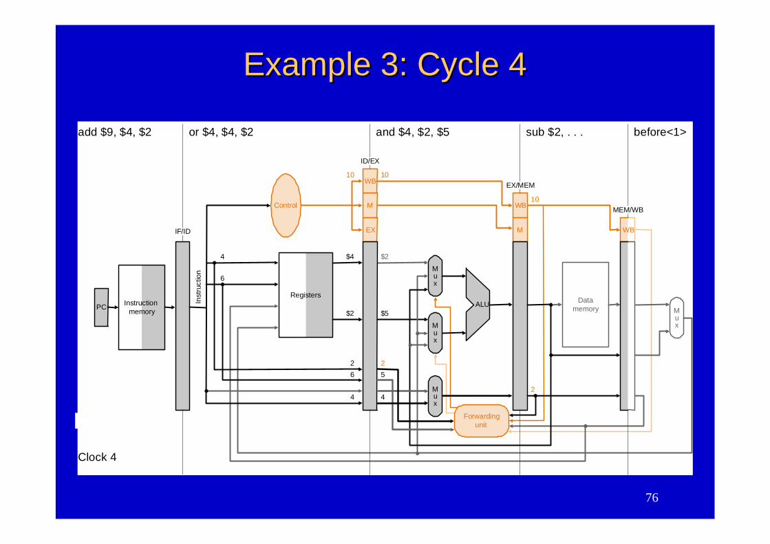
Example 3: Cycle 4Example 3: Cycle 4
Fig. 6.41
PC Instructionmemory
Registers
Mux
Mux
Mux
EX
M
WB
M
WB
Datamemory
Mux
Forwardingunit
Inst
ruct
ion
IF/ID
or $4, $4, $2 and $4, $2, $5
ID/EX
sub $2, . . .
EX/MEM
before<1>
MEM/WB
add $9, $4, $2
Clock 4
4
6
10 10
$4
$2
6
2
4
$2
$5
5
2
4
Control
ALU
10
2
WB
77
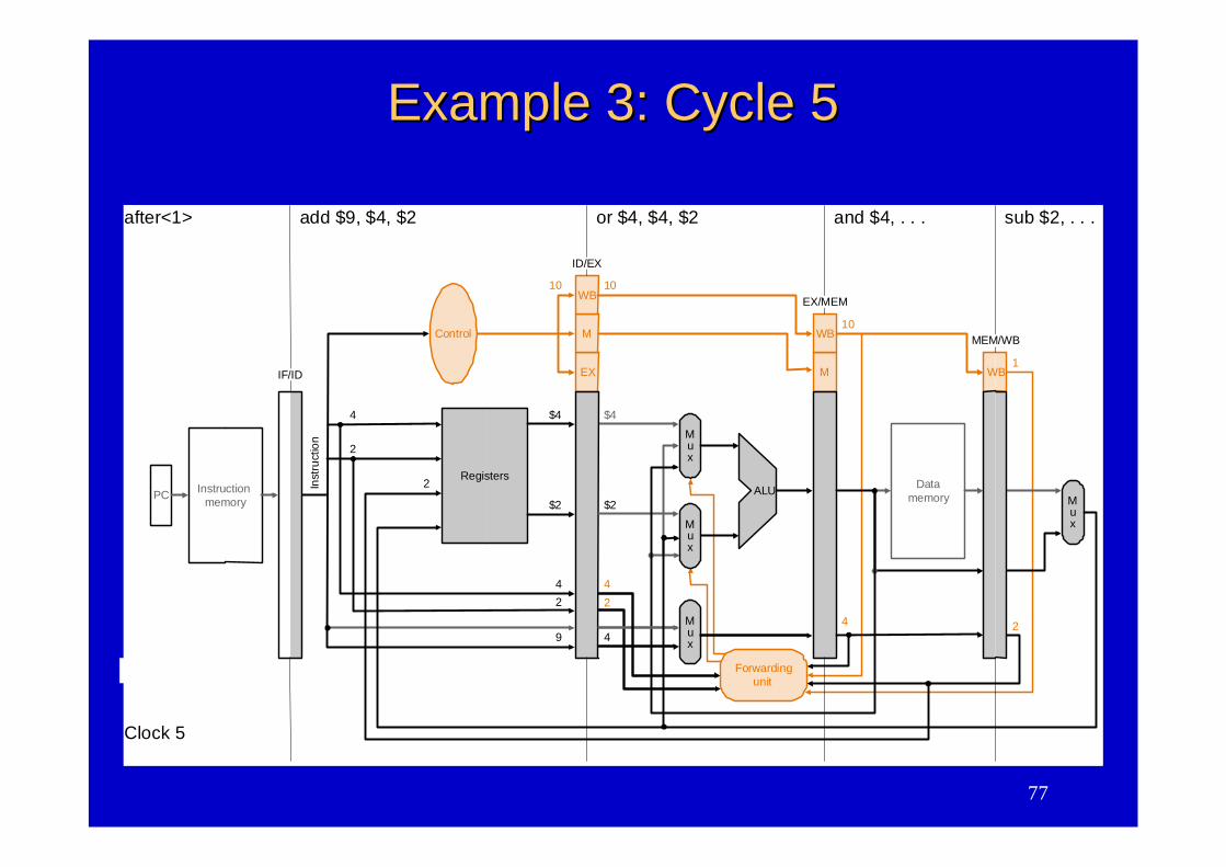
Example 3: Cycle 5Example 3: Cycle 5
Fig. 6.42
PC Instructionmemory
Registers
Mux
Mux
Mux
EX
M
WB
M
WB
Datamemory
Mux
Forwardingunit
Inst
ruct
ion
IF/ID
add $9, $4, $2 or $4, $4, $2
ID/EX
and $4, . . .
EX/MEM
sub $2, . . .
MEM/WB
after<1>
Clock 5
4
2
10 10
$4
$2
2
4
9
$4
$2
4
2
24
Control
ALU
10
WB
2
1
4
78
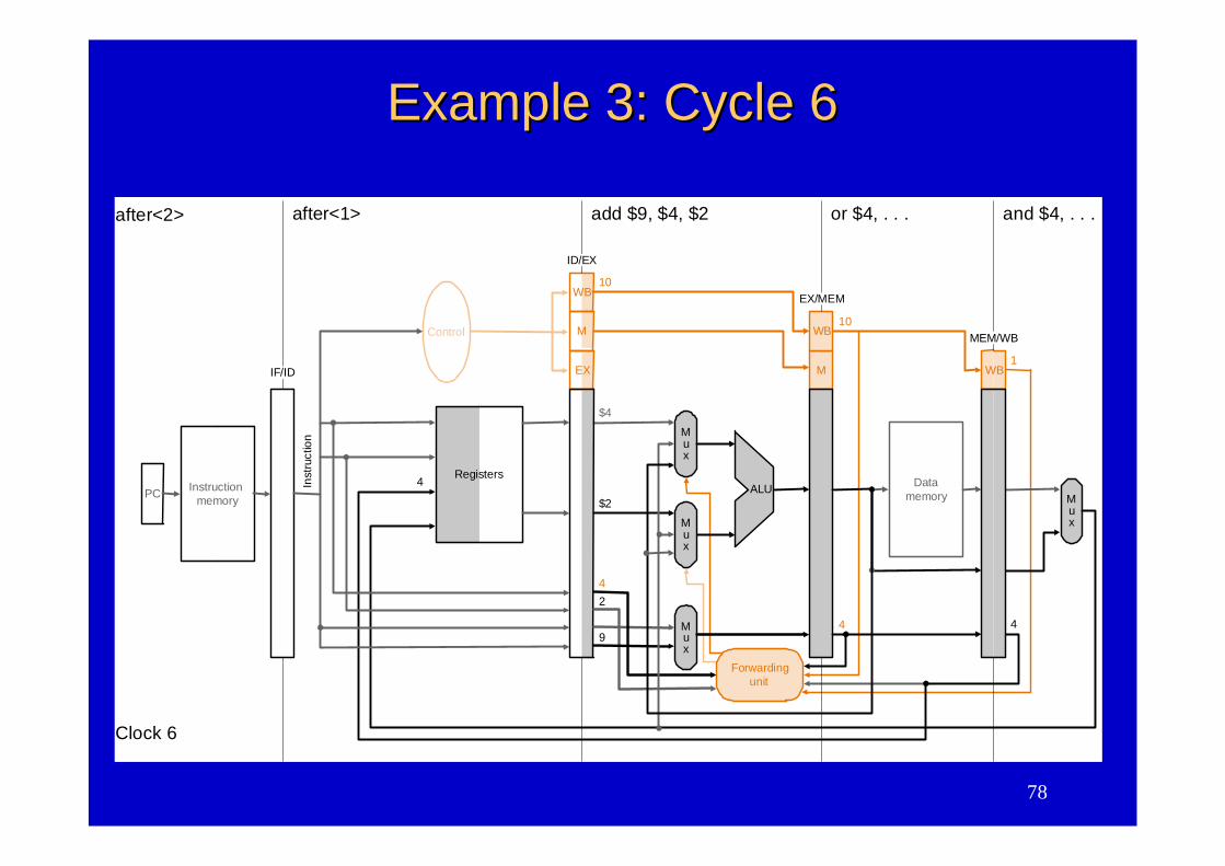
Example 3: Cycle 6Example 3: Cycle 6
Fig. 6.42
PC Instructionmemory
Mux
Mux
Mux
EX
M
WB
M
WB
Datamemory
Mux
Forwardingunit
after<1>after<2> add $9, $4, $2 or $4, . . .
EX/MEM
and $4, . . .
MEM/WB
Clock 6
10
$4
$2
2
4
9
ALU
10
4
WB
4
1
Registers
Inst
ruct
ion
IF/ID
ID/EX
4
Control
79
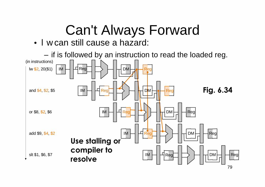
•lw can still cause a hazard:–if is followed by an instruction to read the loaded reg.
Reg
IM
Reg
Reg
IM
lw $2, 20($1)
(in instructions)
and $4, $2, $5
IM Reg DM Reg
IM DM Reg
IM DM Reg
or $8, $2, $6
add $9, $4, $2
slt $1, $6, $7
DM Reg
Reg
Reg
DM
Can't Always Forward
Use stalling orcompiler toresolve
Fig. 6.34
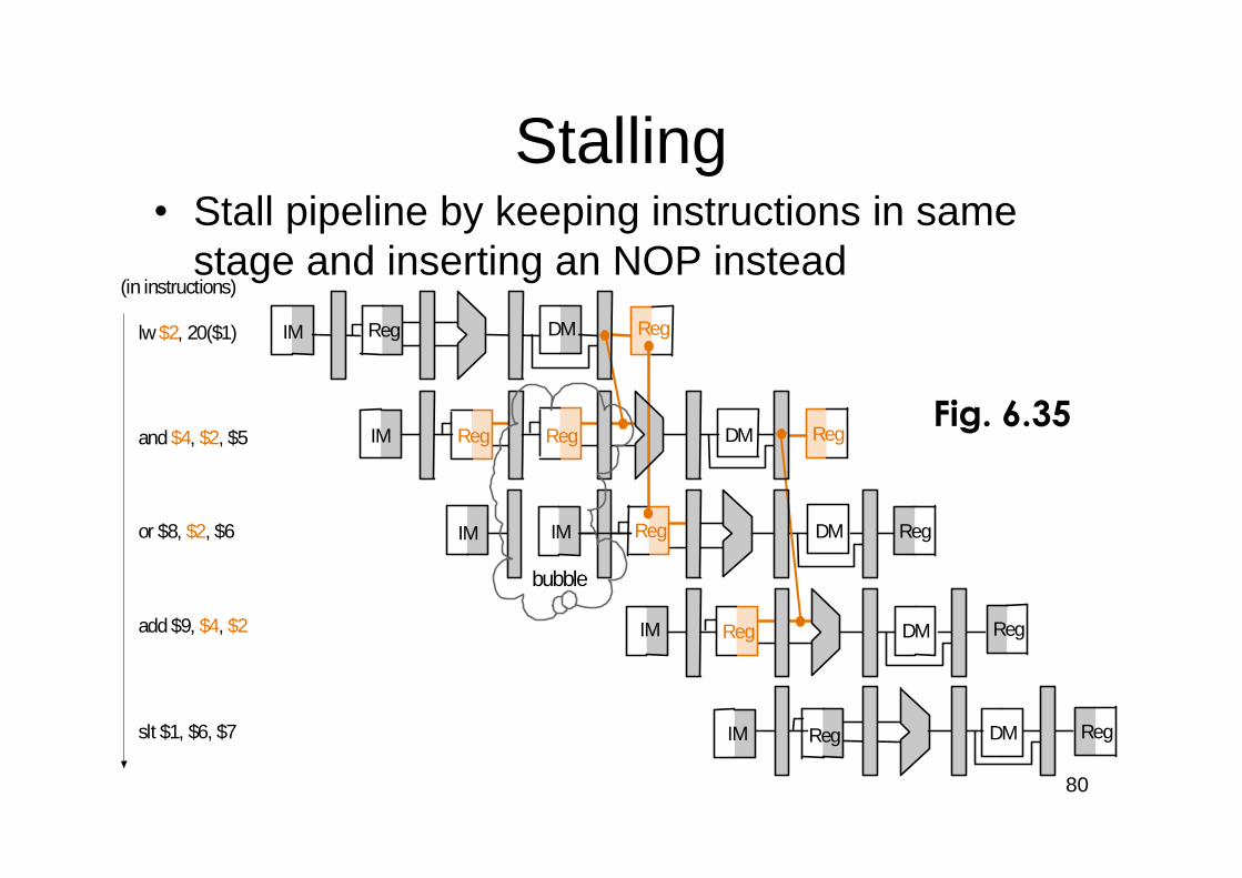
80
Stalling•Stall pipeline by keeping instructions in same
stage and inserting an NOP instead
lw$2, 20($1)
order(in instructions)
and $4, $2, $5
or $8, $2, $6
add $9, $4, $2
slt $1, $6, $7
Reg
IM
Reg
Reg
IM DM
IM Reg DM RegIM
IM DM Reg
IM DM Reg
DM Reg
RegReg
Reg
bubble
Fig. 6.35
81
PCInstruction
memory
Registers
Mux
Mux
Mux
Control
ALU
EX
M
WB
M
WB
WB
ID/EX
EX/MEM
MEM/WB
Datamemory
Mux
Hazarddetection
unit
Forwardingunit
0
Mux
IF/ID
Inst
ruct
ion
ID/EX.MemReadIF
/IDW
rite
PC
Writ
e
ID/EX.RegisterRt
IF/ID.RegisterRd
IF/ID.RegisterRtIF/ID.RegisterRt
IF/ID.RegisterRs
RtRs
Rd
Rt EX/MEM.RegisterRd
MEM/WB.RegisterRd
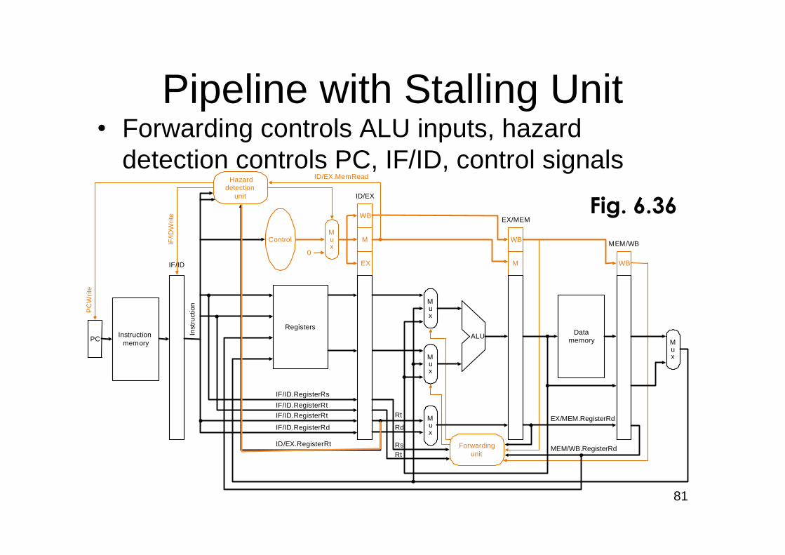
Pipeline with Stalling Unit•Forwarding controls ALU inputs, hazard
detection controls PC, IF/ID, control signals
Fig. 6.36
82
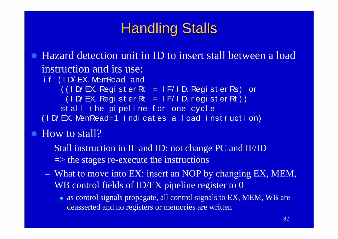
Handling StallsHandling Stalls
Hazard detection unit in ID to insert stall between a loadinstruction and its use:if (ID/EX.MemRead and
((ID/EX.RegisterRt = IF/ID.RegisterRs) or(ID/EX.RegisterRt = IF/ID.registerRt))stall the pipeline for one cycle
(ID/EX.MemRead=1 indicates a load instruction)
How to stall?–Stall instruction in IF and ID: not change PC and IF/ID
=> the stages re-execute the instructions–What to move into EX: insert an NOP by changing EX, MEM,
WB control fields of ID/EX pipeline register to 0 as control signals propagate, all control signals to EX, MEM, WB are
deasserted and no registers or memories are written
83
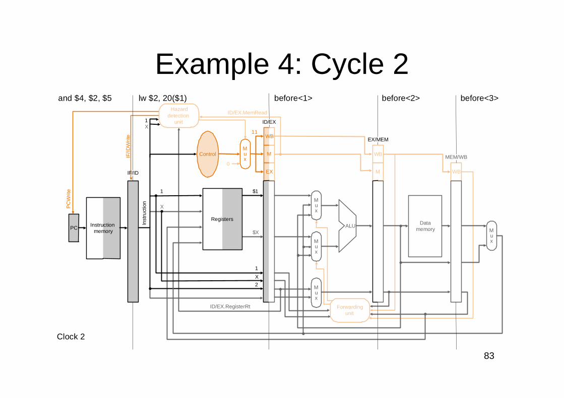
Example 4: Cycle 2Hazard
detectionunit
0
MuxIF/ID
Writ
e
PC
Writ
e
ID/EX.RegisterRt
ID/EX.MemRead
M
WB
$1
$X
X
1
2
before<3>
PC Instructionmemory
Registers
Mux
Mux
Mux
EX WB
Datamemory
Mux
Forwardingunit
Inst
ruct
ion
IF/ID
ID/EX
EX/MEM
MEM/WB
and $4, $2, $5 lw $2, 20($1) before<1> before<2>
Clock 2
1
1
X
X11
Control
ALU
M
WB
84
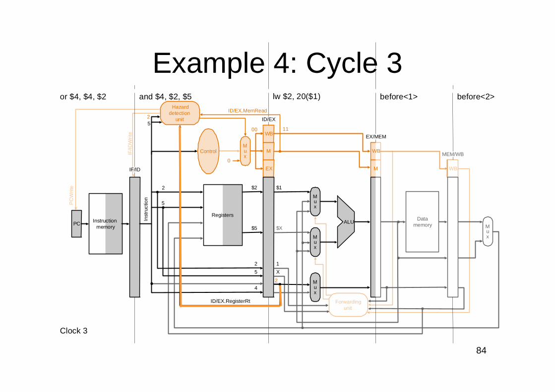
Example 4: Cycle 3Hazard
detectionunit
0
MuxIF
/IDW
rite
PC
Writ
e
ID/EX.RegisterRt
lw $2, 20($1)
PC Instructionmemory
Registers
Mux
Mux
Mux
EX
M
WB
WB
Datamemory
Mux
Forwardingunit
Inst
ruct
ion
IF/ID
and $4, $2, $5
ID/EX
before<1>
EX/MEM
before<2>
MEM/WB
or $4, $4, $2
Clock 3
2
5
2
500 11
$2
$5
5
2
4
$1
$X
X
1
2
Control
ALU
M
WB
ID/EX.MemRead
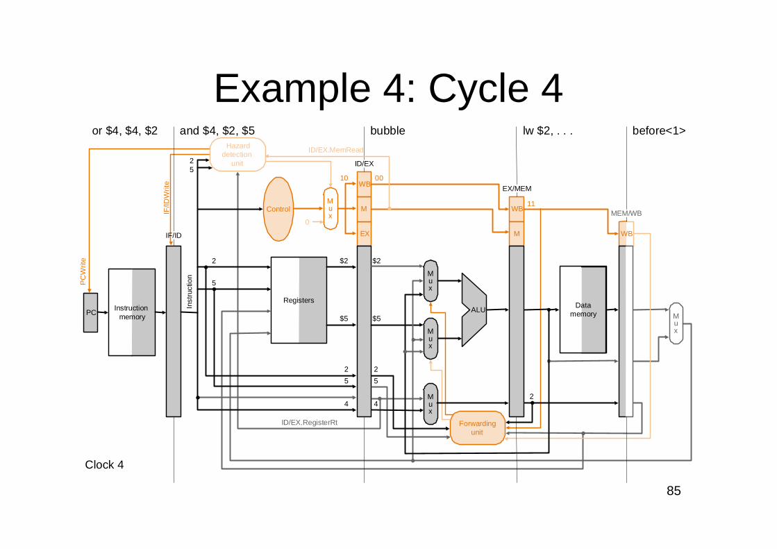
85
$2
$5
5
2
24
WB
Hazarddetection
unit
0
MuxIF
/IDW
rite
PC
Writ
e
ID/EX.RegisterRt
PCInstruction
memory
Registers
Mux
Mux
Mux
EX
M
WB
Datamemory
Mux
Inst
ruct
ion
IF/ID
and $4, $2, $5 bubble
ID/EX
lw $2, . . .
EX/MEM
before<1>
MEM/WB
Clock 4
2
2
5
510
11
00
$2
$5
5
2
4
Control
ALU
M
WB
Forwardingunit
ID/EX.MemRead
or $4, $4, $2
Example 4: Cycle 4
86
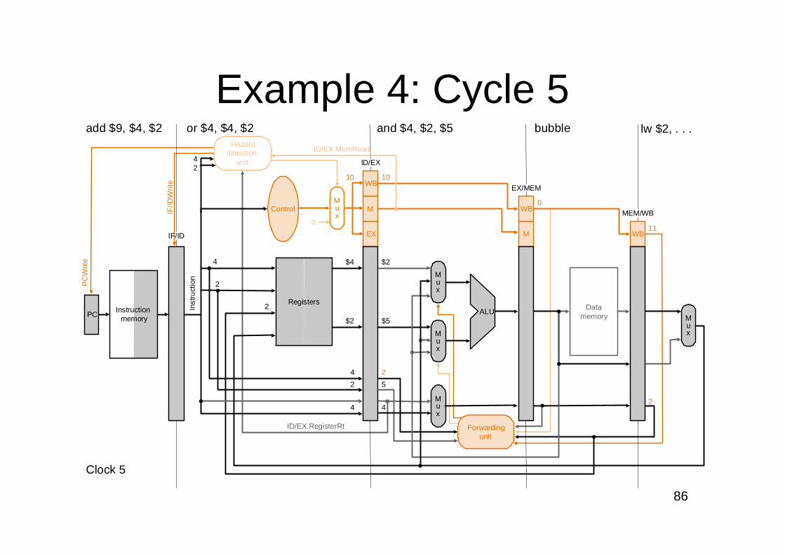
Hazarddetection
unit
0
MuxIF
/IDW
rite
PC
Writ
e
ID/EX.RegisterRt
2
bubble lw $2, . . .
PCInstruction
memory
Registers
Mux
Mux
Mux
EX
M
WB
M
WB
Datamemory
Mux
Forwardingunit
Inst
ruct
ion
IF/ID
and $4, $2, $5
ID/EX
EX/MEM
MEM/WB
add $9, $4, $2
Clock 5
2
210 10
11
$4
$2
2
4
4
4
2
4
$2
$5
5
2
4
Control
ALU
0
WB
ID/EX.MemRead
or $4, $4, $2
Example 4: Cycle 5
87
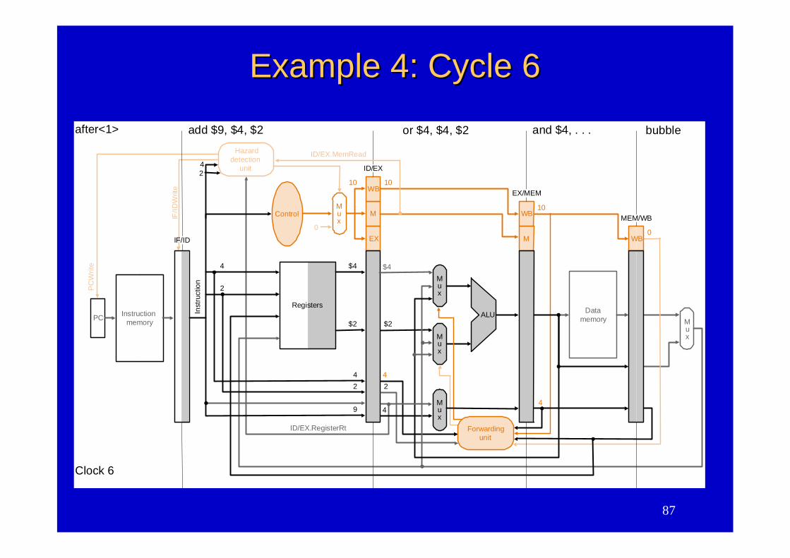
Example 4: Cycle 6Example 4: Cycle 6
Fig. 6.49
PC Instructionmemory
Hazarddetection
unit
0
MuxIF
/IDW
rite
PC
Writ
e
ID/EX.RegisterRt
bubble
Registers
Mux
Mux
EX
M
WB
M
WB
Datamemory
Mux
Inst
ruct
ion
IF/ID
add $9, $4, $2
ID/EX
and $4, . . .
EX/MEM
MEM/WB
Clock 6
4
4
2
210 10
$4
$2
2
4
49
$2
2
Control
ALU
10
WB0
after<1>
Forwardingunit
$4
4
4
or $4, $4, $2
ID/EX.MemRead
Mux
88
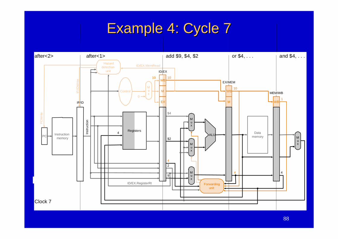
Example 4: Cycle 7Example 4: Cycle 7
Fig. 6.49
Registers
Inst
ruct
ion
ID/EX
4
Control
PC Instructionmemory
IF/ID
Writ
e
PC
Writ
e
add $9, $4, $2 or $4, . . . and $4, . . .after<2> after<1>
Clock 7
Mux
Mux
Mux
EX
M
WB
M
WB
Datamemory
Mux
Forwardingunit
EX/MEM
MEM/WB
10 10
$4
$2
2
4
9
ALU
10
WB
44
1
Hazarddetection
unit
0
Mux
ID/EX.RegisterRt
ID/EX.MemRead
IF/ID
89
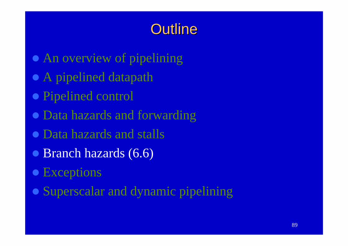
OutlineOutline
An overview of pipeliningA pipelined datapathPipelined controlData hazards and forwardingData hazards and stallsBranch hazards (6.6)ExceptionsSuperscalar and dynamic pipelining
90
Instructionmemory
Address
4
32
0
Add Addresult
Shiftleft 2
Inst
ruct
i on
IF/ID EX/MEM MEM/WB
Mux
0
1
Add
PC
0Writedata
Mux
1Registers
Readdata 1
Readdata 2
Readregister 1
Readregister 2
16Sign
extend
Writeregister
Writedata
Readdata
1
ALUresult
Mux
ALUZero
ID/EX
Datamemory
Address
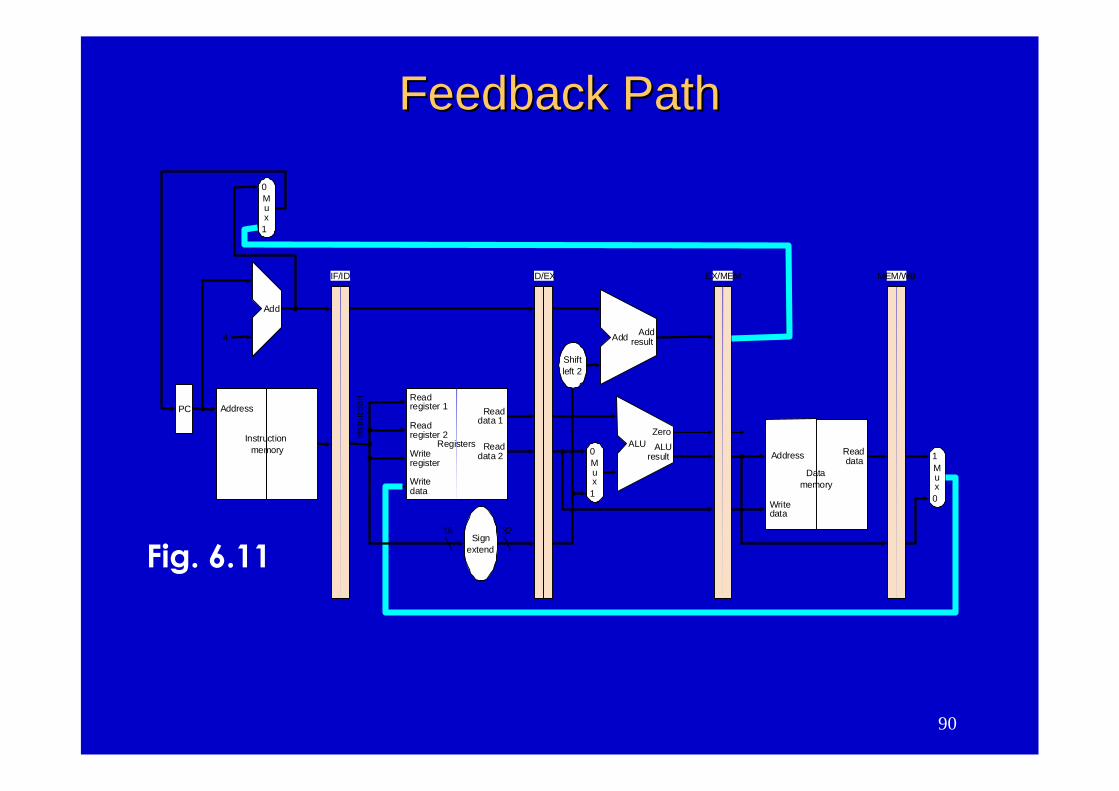
Feedback PathFeedback Path
Fig. 6.11
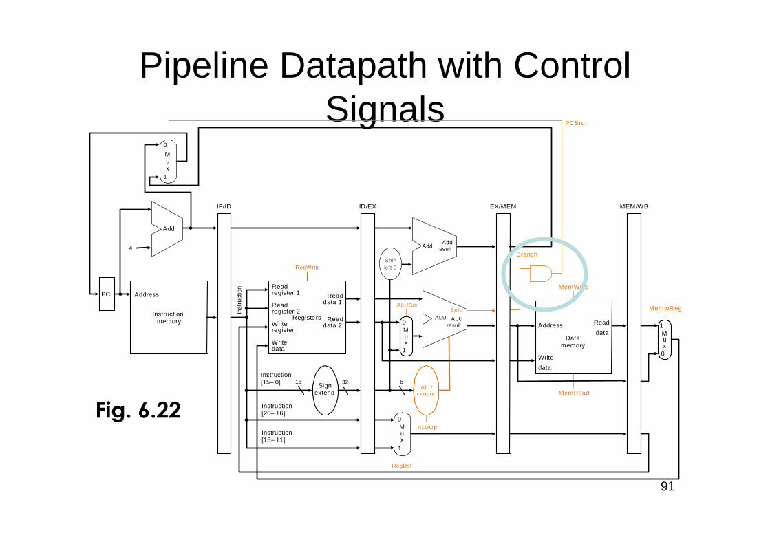
91
Pipeline Datapath with ControlSignals
PC
Instructionmemory
Address
Inst
ruct
ion
Instruction[20–16]
MemtoReg
ALUOp
Branch
RegDst
ALUSrc
4
16 32Instruction[15–0]
0
0Registers
Writeregister
Writedata
Readdata 1
Readdata 2
Readregister 1
Readregister 2
Signextend
Mux
1Write
data
Read
data Mux
1
ALUcontrol
RegWrite
MemRead
Instruction[15–11]
6
IF/ID ID/EX EX/MEM MEM/WB
MemWrite
Address
Datamemory
PCSrc
Zero
AddAdd
result
Shiftleft 2
ALUresult
ALUZero
Add
0
1
Mux
0
1
Mux
Fig. 6.22
92
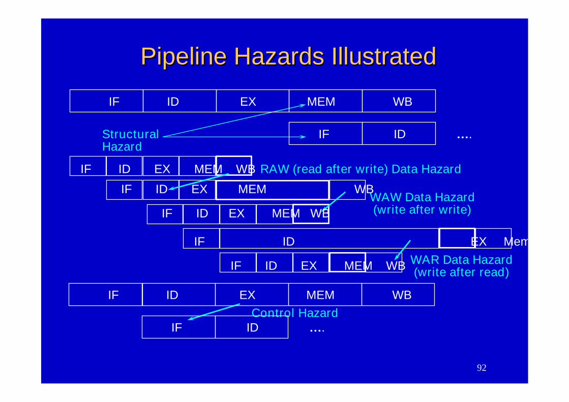
Pipeline Hazards IllustratedPipeline Hazards Illustrated
IF ID EX MEM WB
StructuralHazard
IF ID EX MEM WB
IF ID EX Mem
RAW (read after write) Data Hazard
WAW Data Hazard(write after write)
IF ID EX MEM WB WAR Data Hazard(write after read)
IF ID EX MEM WB
IF ID EX MEM WB
IF ID ….
Control HazardIF ID EX MEM WB
IF ID ….
93
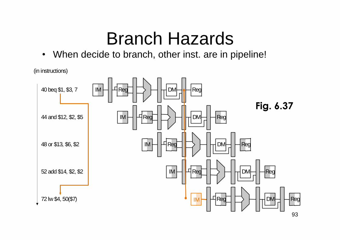
•When decide to branch, other inst. are in pipeline!
Reg
Reg
40 beq $1, $3, 7
order(in instructions)
IM Reg
IM DM
IM DM
IM DM
DM
DM Reg
Reg Reg
Reg
Reg
RegIM
44 and $12, $2, $5
48 or $13, $6, $2
52 add $14, $2, $2
72 lw $4, 50($7)
Reg
Branch Hazards
Fig. 6.37
94
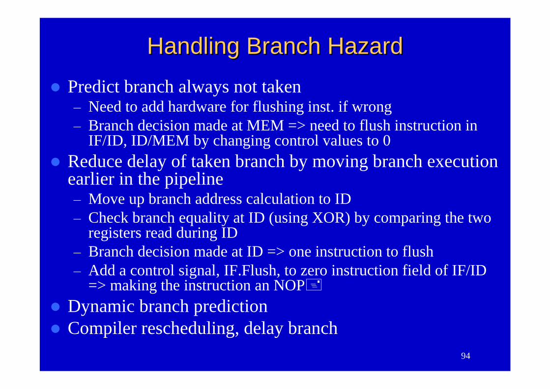
Handling Branch HazardHandling Branch Hazard
Predict branch always not taken–Need to add hardware for flushing inst. if wrong–Branch decision made at MEM => need to flush instruction in
IF/ID, ID/MEM by changing control values to 0Reduce delay of taken branch by moving branch execution
earlier in the pipeline–Move up branch address calculation to ID–Check branch equality at ID (using XOR) by comparing the two
registers read during ID–Branch decision made at ID => one instruction to flush–Add a control signal, IF.Flush, to zero instruction field of IF/ID
=> making the instruction an NOPDynamic branch predictionCompiler rescheduling, delay branch
95
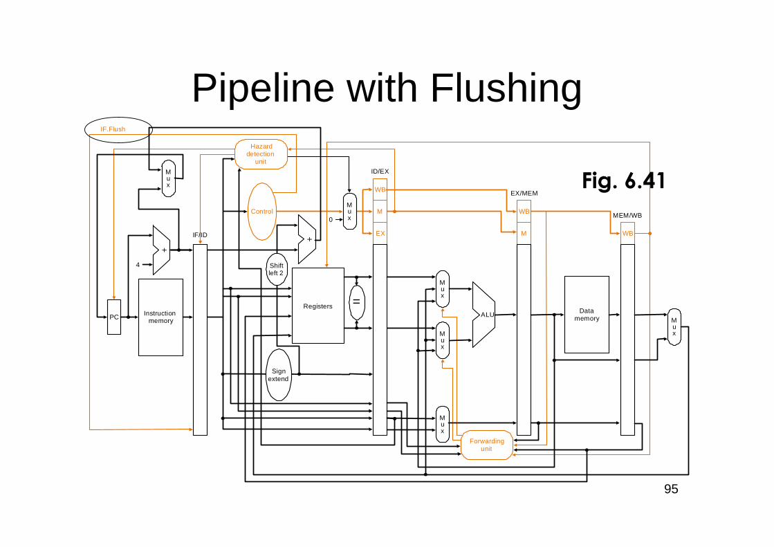
Pipeline with Flushing
PC Instructionmemory
4
Registers
Mux
Mux
Mux
ALU
EX
M
WB
M
WB
WB
ID/EX
0
EX/MEM
MEM/WB
Datamemory
Mux
Hazarddetection
unit
Forwardingunit
IF.Flush
IF/ID
Signextend
Control
Mux
=
Shiftleft 2
Mux
Fig. 6.41
96
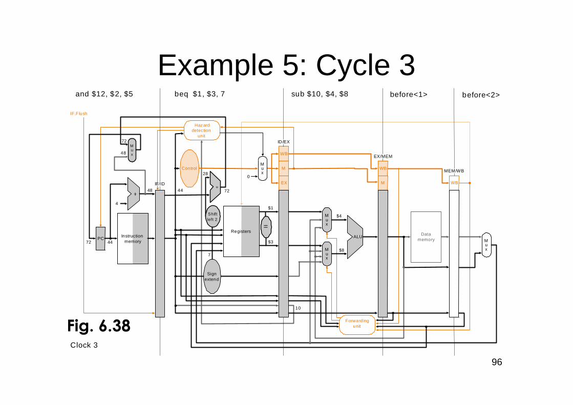
Example 5: Cycle 3
PC Instructionmemory
4
Registers
Signextend
Mux
Mux
Control
EX
M
WB
M
WB
WB
Mux
Hazarddetection
unit
Forwardingunit
Mux
IF.F lush
IF/ID
and $12, $2, $5 beq $1, $3, 7 sub $10, $4, $8
MEM/WB
EX/MEM
ID/EX
Clock 3
72 44
48 44
28
7
$1
$3
10
48
72
72
0
$4
$8
ALU Datamemory
Mux
Shiftleft 2
before<1> before<2>
=
Fig. 6.38
97
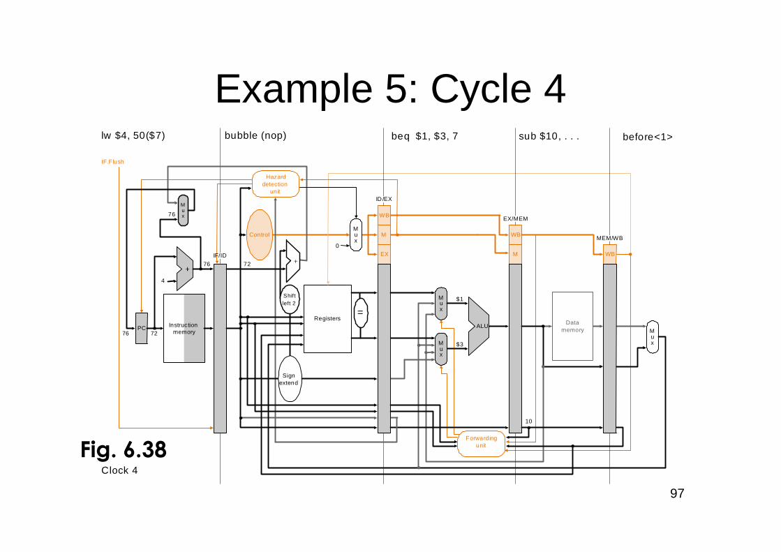
Example 5: Cycle 4
Mux
0
bubble (nop)lw $4, 50($7)
Clock 4
beq $1, $3, 7 sub $10, . . . before<1>
PC Instructionmemory
4
Registers
Signextend
Mux
Mux
Control
EX
M
WB
M
WB
WB
Mux
Hazarddetection
unit
Forwardingunit
IF.F lush
IF/ID
MEM/WB
EX/MEM
ID/EX
76 72
76 72
$1
$3
10
76
ALU Datamemory
Mux
Shiftleft 2
=
Fig. 6.38
98
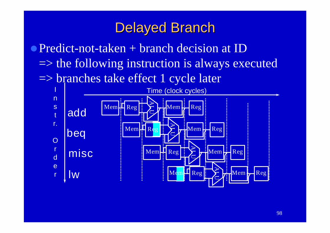
Predict-not-taken + branch decision at ID=> the following instruction is always executed=> branches take effect 1 cycle later
Instr.
Order
Time (clock cycles)
add
beq
misc
AL
UMem Reg Mem Reg
AL
UMem Reg Mem Reg
Mem
AL
UReg Mem Reg
lw Mem
AL
UReg Mem Reg
Delayed BranchDelayed Branch
99
Dynamic Branch PredictionDynamic Branch Prediction Performance = ƒ(accuracy, cost of misprediction)Branch History Table: Lower bits of PC address
index table of 1-bit values–Says whether or not branch taken last time–No address check
Problem: in a loop, 1-bit BHT will cause twomispredictions (avg is 9 iterations before exit):–End of loop case, when it exits instead of looping as
before–First time through loop on next time through code, when
it predicts exit instead of looping
100
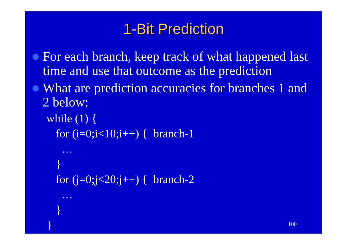
11--Bit PredictionBit Prediction
For each branch, keep track of what happened lasttime and use that outcome as the prediction
What are prediction accuracies for branches 1 and2 below:while (1) {
for (i=0;i<10;i++) { branch-1…
}for (j=0;j<20;j++) { branch-2…
}}
101
22--Bit PredictionBit Prediction
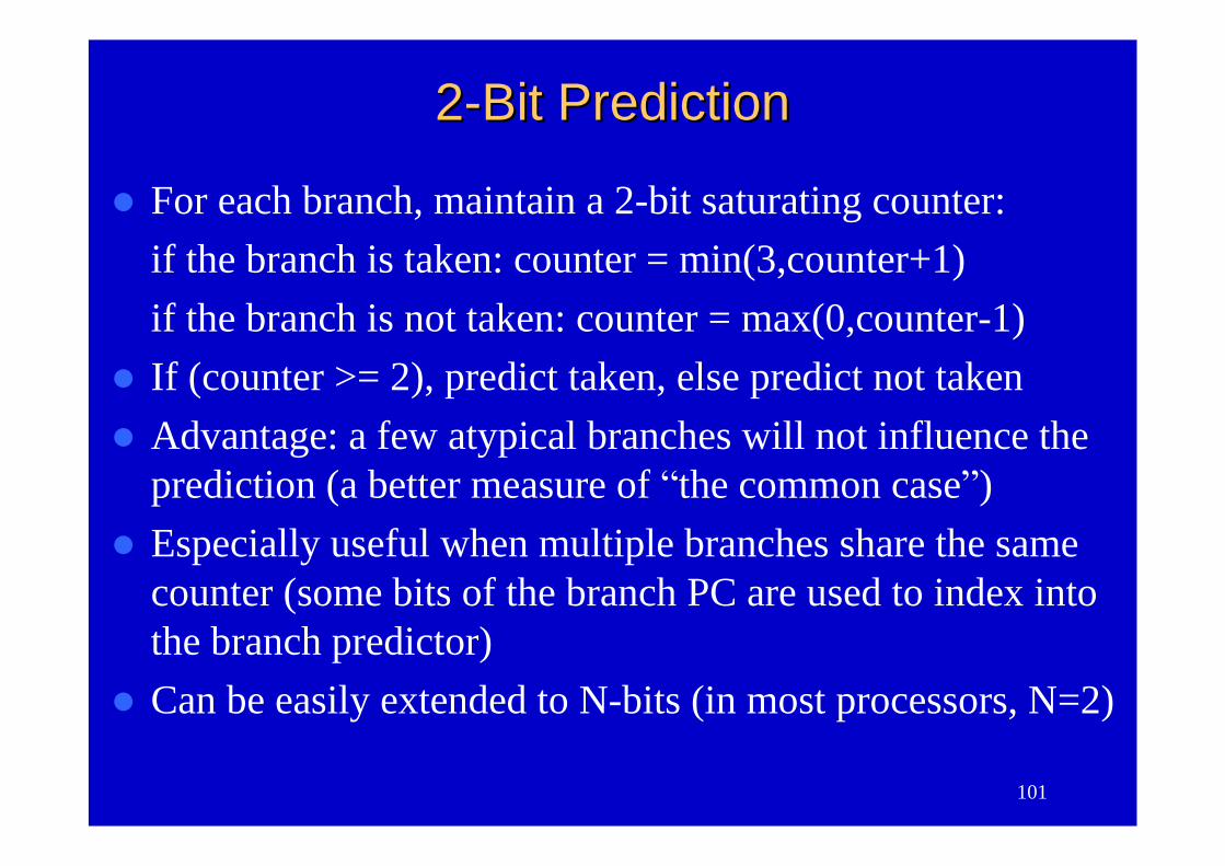
For each branch, maintain a 2-bit saturating counter:if the branch is taken: counter = min(3,counter+1)if the branch is not taken: counter = max(0,counter-1)
If (counter >= 2), predict taken, else predict not takenAdvantage: a few atypical branches will not influence the
prediction (a better measure of “the common case”)Especially useful when multiple branches share the same
counter (some bits of the branch PC are used to index intothe branch predictor)
Can be easily extended to N-bits (in most processors, N=2)
102
NN--bit Branch Prediction Buffersbit Branch Prediction Buffers
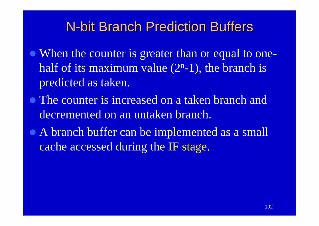
When the counter is greater than or equal to one-half of its maximum value (2n-1), the branch ispredicted as taken.
The counter is increased on a taken branch anddecremented on an untaken branch.
A branch buffer can be implemented as a smallcache accessed during the IF stage.
103
NN--bit Branch Prediction Buffersbit Branch Prediction Buffers
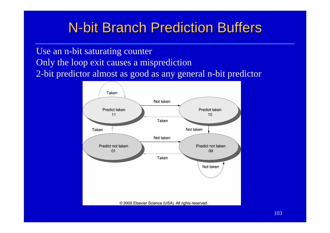
Use an n-bit saturating counterOnly the loop exit causes a misprediction2-bit predictor almost as good as any general n-bit predictor
104
Basic Branch Prediction BuffersBasic Branch Prediction Buffers
IR:
PC:
Branch Instruction
+ Branch Target
BHT
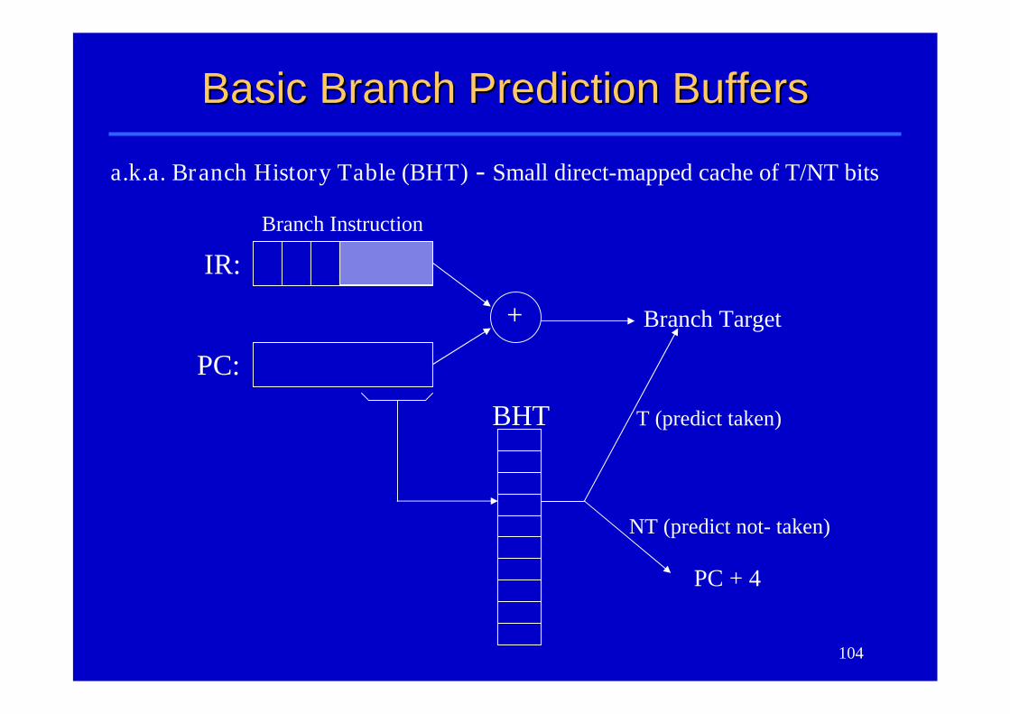
a.k.a. Branch History Table (BHT) - Small direct-mapped cache of T/NT bits
PC + 4
T (predict taken)
NT (predict not- taken)
105
OutlineOutline
An overview of pipeliningA pipelined datapathPipelined controlData hazards and forwardingData hazards and stallsBranch hazardsExceptionsSuperscalar and dynamic pipelining
106
What about Exceptions?What about Exceptions?
•Another form of branch hazard–How to stop the pipeline? restart?–Who caused the interrupt?–Who to serve first, if multiple interrupts at the
same time?
107
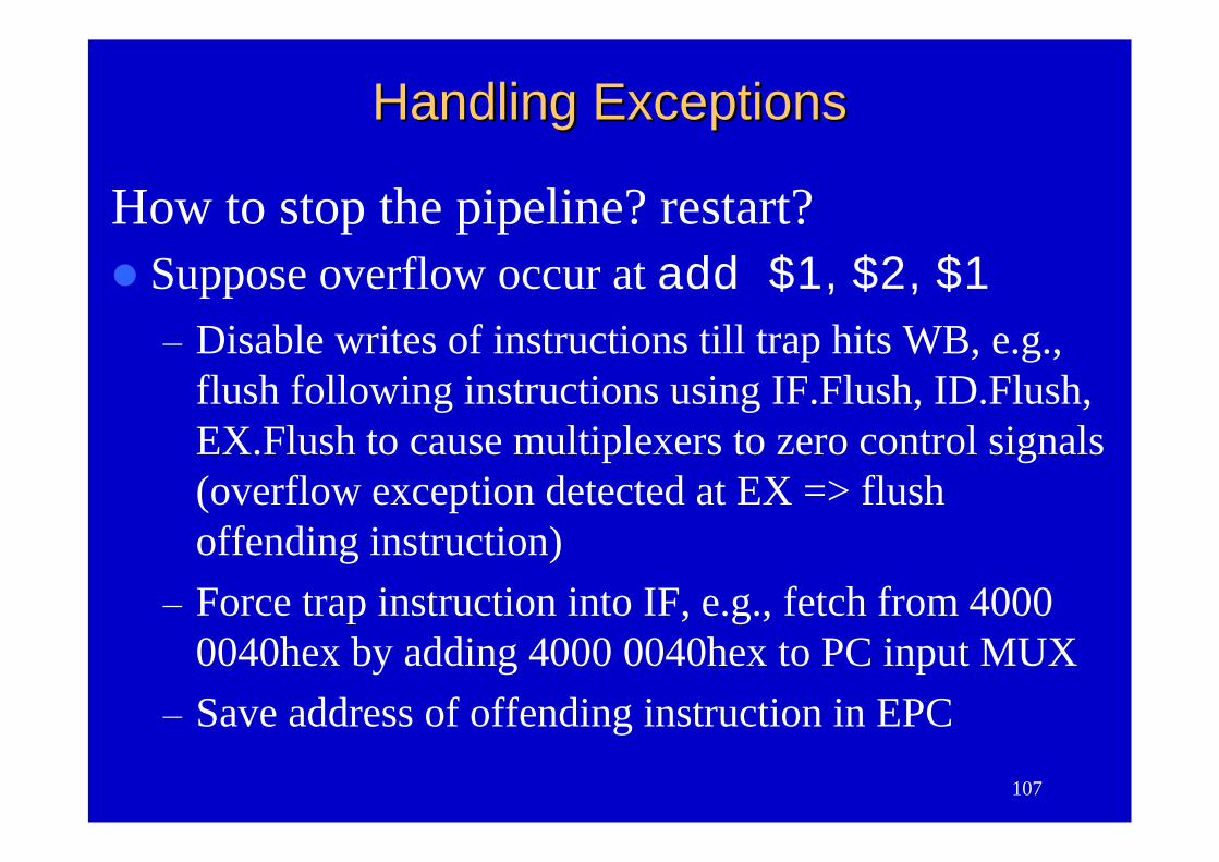
Handling ExceptionsHandling Exceptions
How to stop the pipeline? restart?Suppose overflow occur at add $1,$2,$1
–Disable writes of instructions till trap hits WB, e.g.,flush following instructions using IF.Flush, ID.Flush,EX.Flush to cause multiplexers to zero control signals(overflow exception detected at EX => flushoffending instruction)
–Force trap instruction into IF, e.g., fetch from 40000040hex by adding 4000 0040hex to PC input MUX
–Save address of offending instruction in EPC
108
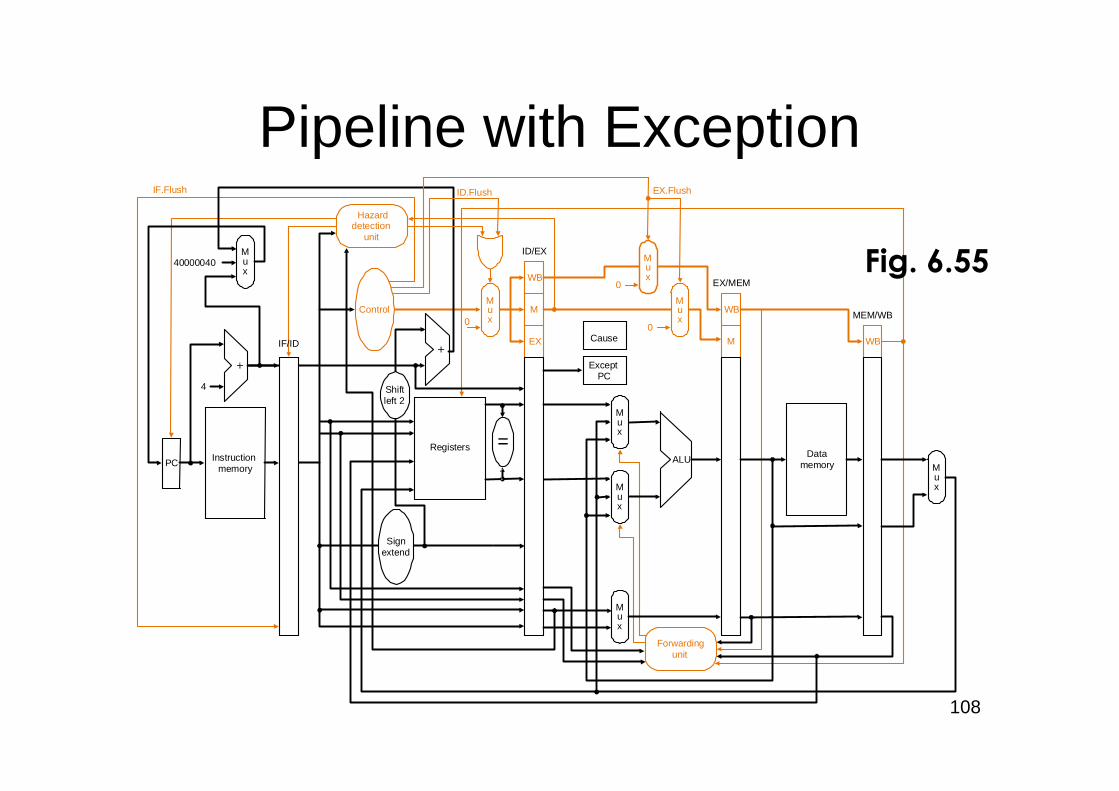
Pipeline with Exception
PC Instructionmemory
4
Registers
Signextend
Mux
Mux
Mux
Control
ALU
EX
M
WB
M
WB
WB
ID/EX
EX/MEM
MEM/WB
Mux
Datamemory
Mux
Hazarddetection
unit
Forwardingunit
IF.Flush
IF/ID
=
ExceptPC
40000040
0
Mux
0
Mux
0
Mux
ID.Flush EX.Flush
Cause
Shiftleft 2
Fig. 6.55
109
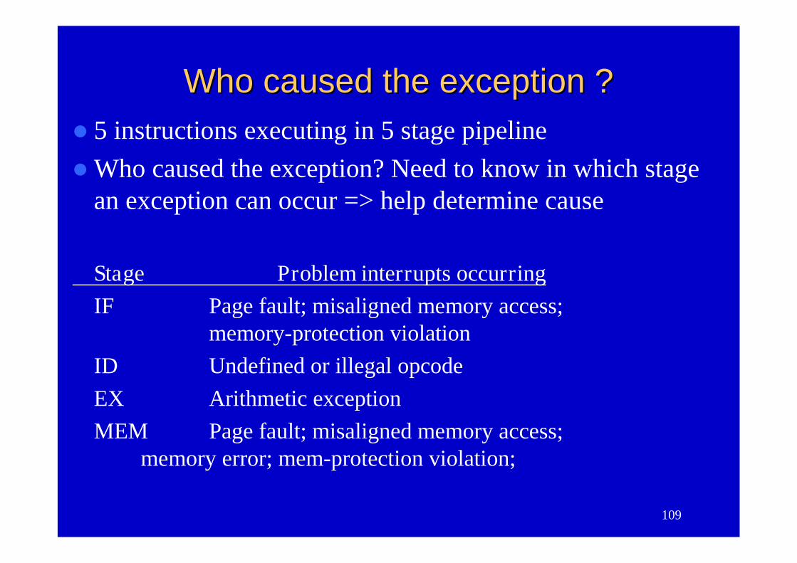
Who caused the exception ?Who caused the exception ?5 instructions executing in 5 stage pipelineWho caused the exception? Need to know in which stage
an exception can occur => help determine cause
Stage Problem interrupts occurringIF Page fault; misaligned memory access;
memory-protection violationID Undefined or illegal opcodeEX Arithmetic exceptionMEM Page fault; misaligned memory access;
memory error; mem-protection violation;
110
When to Serve?When to Serve?
Who to serve first, if multiple interrupts atthe same time?–Multiple interrupts: use priority hardware to
choose the earliest instruction to interrupt–External interrupts: flexible in when to
interrupt
111
OutlineOutline
An overview of pipeliningA pipelined datapathPipelined controlData hazards and forwardingData hazards and stallsBranch hazardsExceptionsSuperscalar and dynamic pipelining
112
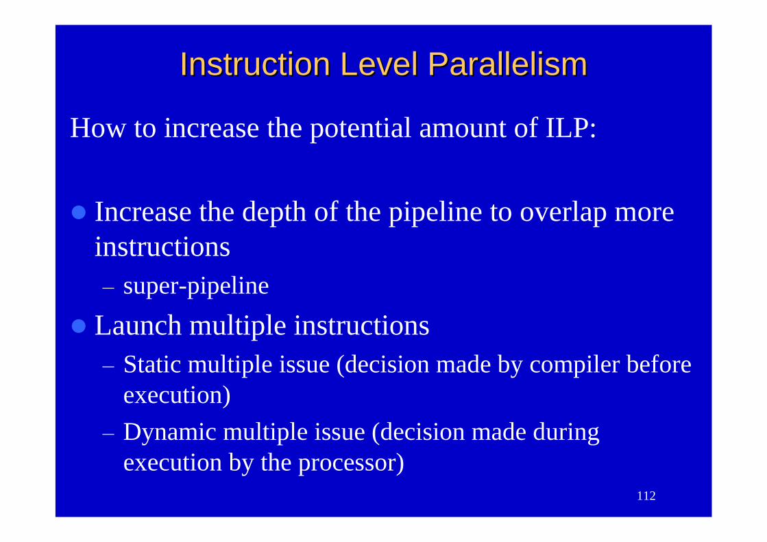
Instruction Level ParallelismInstruction Level Parallelism
How to increase the potential amount of ILP:
Increase the depth of the pipeline to overlap moreinstructions–super-pipeline
Launch multiple instructions–Static multiple issue (decision made by compiler before
execution)–Dynamic multiple issue (decision made during
execution by the processor)
113
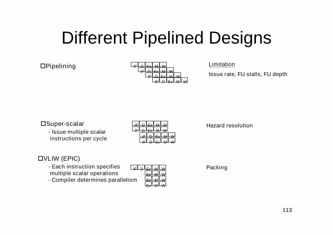
Different Pipelined DesignsPipelining
Super-scalar- Issue multiple scalarinstructions per cycle
VLIW (EPIC)- Each instruction specifiesmultiple scalar operations
- Compiler determines parallelism
Limitation
Issue rate, FU stalls, FU depth
Hazard resolution
Packing
IF D Ex M W
IF D Ex
IF D Ex M WIF D Ex M W
M W
IF D Ex M WIF D Ex M W
IF D Ex M WIF D Ex M W
IF D Ex M WEx M WEx M WEx M W
114
Static Multiple IssueStatic Multiple Issue
Use compiler to assist with packinginstructions and handling hazard
Very Long Instruction Word (VLIW)Explicitly Parallel Instruction Computer
(EPIC) (Intel IA-64)
115
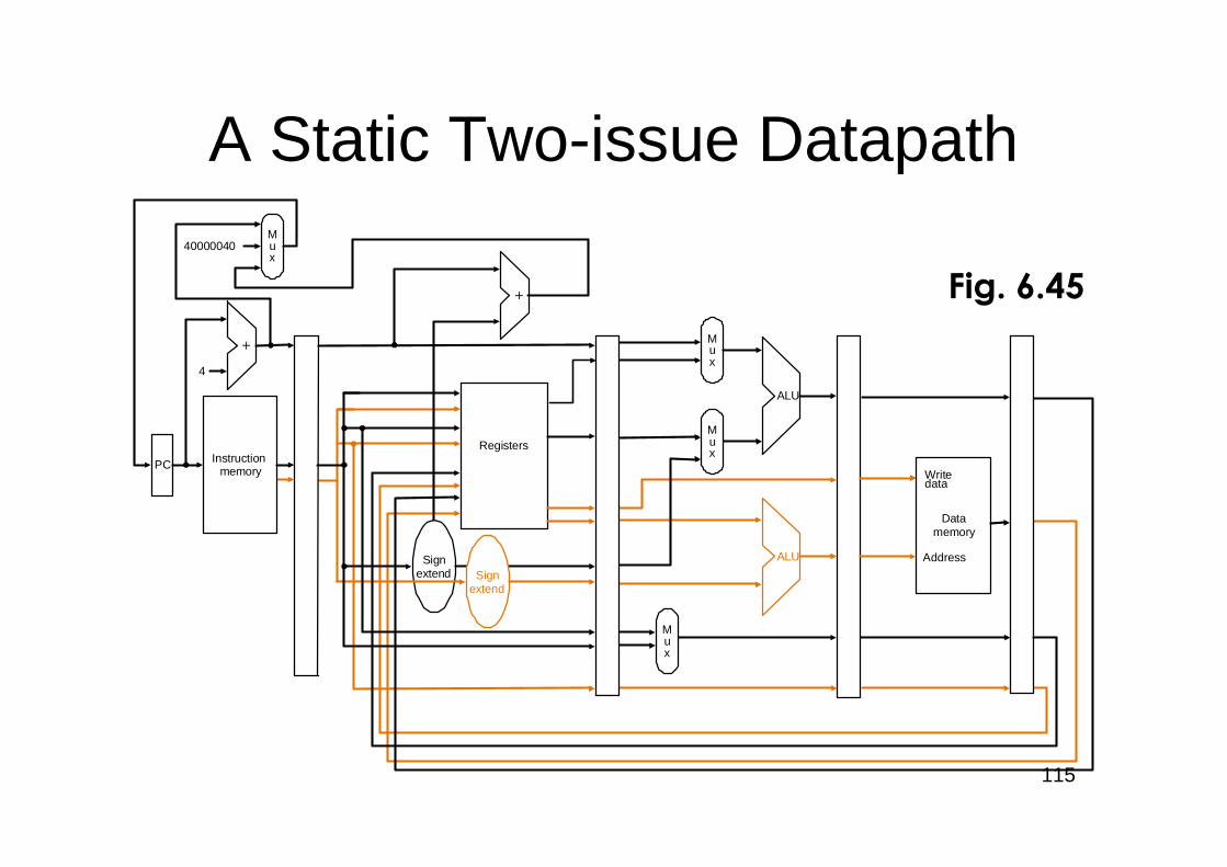
A Static Two-issue Datapath
PC Instructionmemory
4
RegistersMux
Mux
ALU
Mux
Datamemory
Mux
40000040
Signextend Sign
extend
ALU Address
Writedata
Fig. 6.45
116
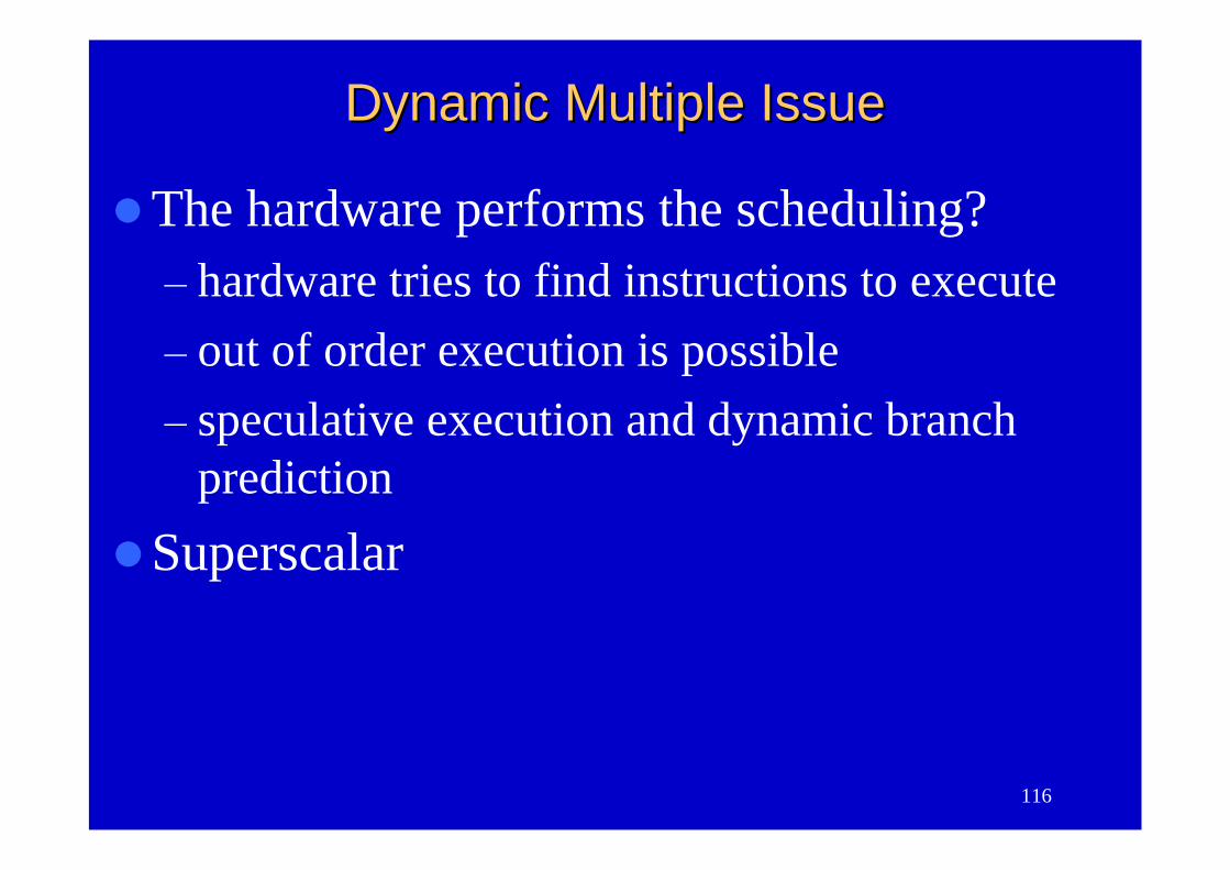
Dynamic Multiple IssueDynamic Multiple Issue
The hardware performs the scheduling?–hardware tries to find instructions to execute–out of order execution is possible–speculative execution and dynamic branch
prediction
Superscalar
117
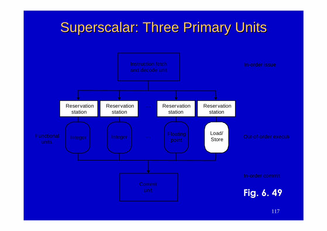
Superscalar: Three Primary UnitsSuperscalar: Three Primary Units
Commitunit
Instruction fetchand decode unit
…
In-order issue
In-order commit
Load/Store
Floatingpoint
IntegerInteger …Functionalunits
Out-of-order execute
Reservationstation
Reservationstation
Reservationstation
Reservationstation
Fig. 6. 49
118
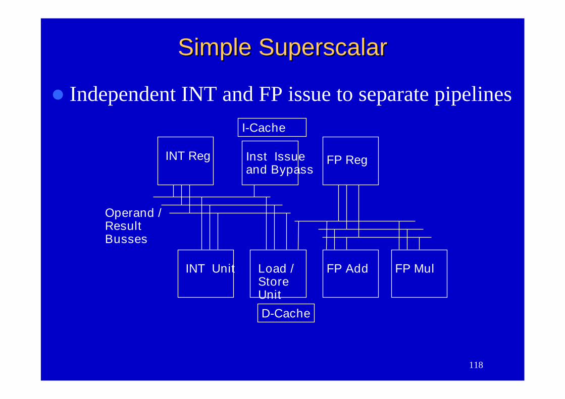
Independent INT and FP issue to separate pipelines
INT Reg Inst Issueand Bypass
FP Reg
Operand /ResultBusses
INT Unit
I-Cache
Load /StoreUnit
FP Add FP Mul
D-Cache
Simple SuperscalarSimple Superscalar
119
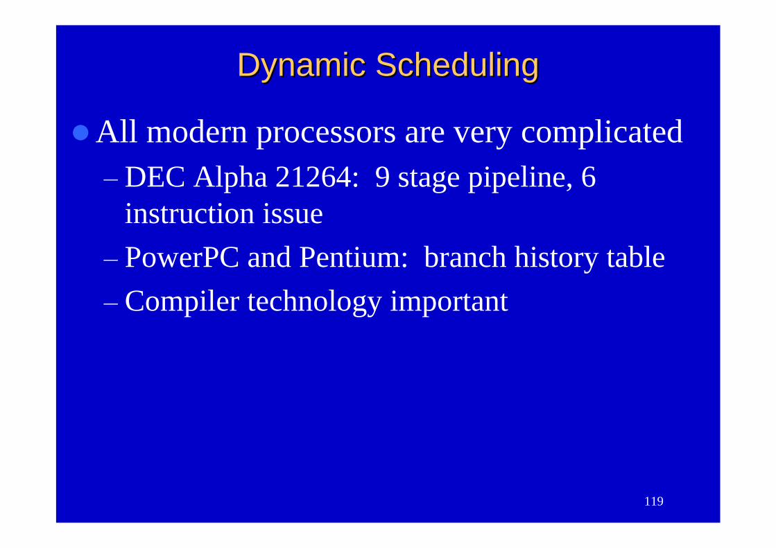
Dynamic SchedulingDynamic Scheduling
All modern processors are very complicated–DEC Alpha 21264: 9 stage pipeline, 6
instruction issue–PowerPC and Pentium: branch history table–Compiler technology important
120
SummarySummary
Pipelines pass control information down thepipe just as data moves down pipe
Forwarding/stalls handled by local controlExceptions stop the pipelineMIPS instruction set architecture made
pipeline visible (delayed branch, delayedload)
More performance from deeper pipelines,parallelism


![Pipelining & Parallel Processing - ics.kaist.ac.krics.kaist.ac.kr/ee878_2018f/[EE878]3 Pipelining and Parallel Processing.pdf · Pipelining processing By using pipelining latches](https://img.pdfslide.net/doc/110x75/5d40e26d88c99391748d47fb/pipelining-parallel-processing-icskaistackricskaistackree8782018fee8783.jpg)


![Software Pipelining and Superblock Scheduling: Compilation … · pipelining [6, 7] and superblock scheduling [8, 9, 10]. Software pipelining overlaps successive basic blocks from](https://img.pdfslide.net/doc/110x75/5f0469bd7e708231d40dd891/software-pipelining-and-superblock-scheduling-compilation-pipelining-6-7-and.jpg)