Embed Size (px)
Citation preview
Chapter 6Routing, Interface Assignment and RelatedCross-layer Issues in Multiradio Wireless MeshNetworks
Leonardo Badia, Marco Conti, Sajal K. Das, Luciano Lenzini,and Habiba Skalli
Abstract Many technological standards for Wireless Mesh Networks include thepossibility to use several nonoverlapping channels for data transmission. This repre-sents an opportunity that can be exploited by equipping the terminals with multiplenetwork interfaces. This opens up an interesting challenge, namely, how to simul-taneously use different frequencies, so as to limit collisions and therefore activatemultiple simultaneous transmissions in the same geographic area. At the same time,this poses new issues; for example, network connectivity is reduced, because nodesthat do not interfere are also unable to communicate with each other. Thus, morecomplex interface management techniques are required. Moreover, a paradigm shiftfrom the classic routing schemes is needed. Usual approaches are not always satis-factory because they often use shortest-path heuristic and tend to concentrate trans-missions to certain nodes. To efficiently exploit the presence of multiple channelsinstead, a proper routing algorithm should avoid congested links and possibly makeuse of an estimation of the actual network traffic. Therefore, cross-layer informationexchange can be useful for an efficient functioning of the routing protocols. In thischapter, we will analyze all these issues and propose and identify possible solutions.
6.1 Introduction
Wireless mesh networks (WMNs) [1, 2] are a network technology currently underdevelopment to provide end users with broadband wireless connectivity. In suchsystems, each mobile terminal owned by an end user, called mesh client (MC), islinked through a single radio hop to a mesh router (MR), a fixed infrastructure node.All the MRs are, in turn, interconnected to each other in a multihop fashion so as to
S.K. DasDepartment of Computer Science and Engineering, Center for Research in Wireless Mobility andNetworking (CReWMaN), The University of Texas at Arlington, Arlington, TX 76019-0015, USAe-mail: [email protected]
S. Misra et al. (eds.), Guide to Wireless Mesh Networks, Computer Communications 147and Networks, DOI 10.1007/978-1-84800-909-7 6,c© Springer Science+Business Media LLC 2009
148 L. Badia et al.
form what is referred to as the network backbone. This kind of structure is easy toinstall because several low cost nodes can be added to improve the backbone con-nectivity. Moreover, MRs do not need to be battery-powered, because they can beeasily placed in correspondence with a power outlet. Finally, the all-wireless struc-ture does not require cable deployment, thus making WMNs appealing for connect-ing both vast rural regions and crowded urban areas where cable deployment is notcost-effective.
In general, to attach the WMN to the Internet, some special MRs, called meshaccess points (MAPs), are equipped with wired connections and therefore can takethe role of Internet gateways. Therefore, they usually have better computationalcapabilities than the other MRs, which work as simple relay nodes; for this reason,it is sensible to think of MAPs as the centers of the network management operations.On the other hand, this determines a higher cost of such nodes and therefore theirnumber is reasonably limited. In most cases, just one or two MAPs are used; thiswill be also the case for the examples discussed throughout this chapter.
Because the communication between a MC and its reference MR is single-hop,most of the challenges of the WMN management are at the backbone level. Thispart of the network is similar to other kinds of wireless multihop networks, such asad hoc and sensor networks. Differently from them, however, the main problems inthe inter-MR communication do not relate to mobility and energy saving problems,which are avoided because of the assumptions made above. Instead, other majortechnical issues arise especially when the network size grows (scalability problem).Among them, one of the most challenging is represented by routing [3]. In fact, theperformance of WMNs in this sense is, similar to any other multihop network, lim-ited by wireless interference. The placement of additional relay nodes yet mitigatesthe problem, because it gives additional opportunities for traffic forwarding; how-ever, the performance improvement is often limited and does not linearly scale withthe number of nodes. Thus, the design of efficient routing algorithms plays a keyrole among WMN research topics.
Moreover, WMN solutions are often thought as utilizing existing standards, suchas IEEE 802.11 [4], without any modification. On the one hand, this enables to useoff-the-shelf network cards for the wireless mesh nodes, which keeps the infras-tructure costs low. On the other hand, a straightforward adaptation of existing tech-nologies, without taking into account the specific purposes of WMNs, will result inan inefficient management. In fact, these standards are commonly used in a differ-ent context; in particular, IEEE 802.11 is used almost exclusively in a single-hopfashion, whereas its collision avoidance mechanism is known to suffer from sev-eral problems in multihop scenarios, such as the decrease of network parallelismbecause of the exposed terminal problem [5].
In general, a compromise shall be sought between this inefficient usage and thedesign of entirely new protocols. A possible solution, in this sense, can be the ideaof finding new applications of possibilities already envisioned by the protocol butscarcely used in practice. An example where this concept can be applied concernsthe possibility of exploiting multiple portions of the available wireless spectrum.For example, the IEEE 802.11a/b/g specifications provide multiple channels, some
6 Routing, Interface Assignment and Related Cross-layer Issues 149
of which can be regarded, with a good degree of approximation, as nonoverlapping(specifically, 3 channels for IEEE 802.11b/g and and 12 channels for IEEE 802.11a).
There are two possible approaches to deal with multiple channels. In the major-ity of the literature, it is assumed that they are perfectly nonoverlapping; in thischapter we will consider this case only. There is also an interesting line of research,discussed in more detail in the following, where partial overlap of the channel istaken into account with the aim to exploit it [6]. However, this approach requiresto entirely reformulate the routing problem. The case of perfect nonoverlap is sim-pler, because it allows to regard the routing problem as a multicommodity allocationor a graph coloring issue. Notice that models for studying networks exploiting fre-quency diversity date back before the success of wireless networks, because theywere already investigated, e.g., for optical fiber networks [7].
Although multiple channels can be introduced, and actually they are alreadyavailable in existing standards, terminals are typically configured to operate on asingle radio channel: in fact, in a single-hop scenario, this frequency diversity ismostly introduced to avoid collisions from different networks. In a WMN case,instead, this feature can be used to increase the number of transmissions that canbe exchanged within a neighborhood. This imposes to differently tune the NetworkInterface Cards (NICs) of the involved MRs.
The opportunity given by multiple nonoverlapping channels is better exploitedif more than one NIC is available at a single node. In this way, one can avoid, orat least mitigate, the need for dynamically tuning to a common frequency the inter-faces of MRs that are meant to communicate with each other. As will be discussedin the following, fast frequency-switching transceivers are in fact not always fea-sible. Actually, the cost decrease for commodity hardware makes multi-interfaceterminals economically sustainable, even though in general it is not possible, formany practical reasons to provide each node with a single NIC per every availablechannel. However, as shown in [8], the largest advantage in terms of network capac-ity, intended as traffic that can be transmitted over the network in a collision-freemanner, is present already for a limited (though larger than one) number of NICsper node. The relative performance improvement when the number of interfacesapproaches the number of available channels becomes marginal.
Thus, we will focus on multiradio, i.e., multichannel and multi-interface, WMNs.The investigations carried out in the following concern the strategy to determine thechannels to which the NICs of every node shall be tuned, which can be regarded asa multiple allocation optimization problem, and how this affects routing strategiesover the WMN.
There is a two-fold relationship between the routing and the interface assignmentproblems. First, when the routing algorithm is applied, two nodes i and j can com-municate, and therefore it is possible to route traffic through a network link from i toj, only if they share a common channel assigned to at least one of their NICs. Con-versely, to be realized efficiently, the interface assignment should take into accountthe routing pattern of the network. In fact, because the use of different channelsdecreases not only the mutual interference but also the network connectivity, itshould leave the possibility of connecting the nodes along the main traffic routesand possibly decreasing the number of interfering links.
150 L. Badia et al.
Classic routing protocols for multihop networks [9,10] may be easily extended tosupport multiple interfaces at each node. However, those protocols typically selectshortest-hop routes, which may not be suitable for multichannel networks; as wasnoted in [11], routing metrics based on hop count only should be integrated by alsotaking into account the network load. Moreover, longer paths may be preferable ifthey allow to decrease interference and increase transmission parallelism. At thesame time, more bandwidth should be given to nodes that support higher traffic,i.e., channels assigned to these links should be shared among a fewer number ofnodes. More in general, the interface assignment strategy should be traffic-aware inthe sense that it matches the distribution of traffic load in the mesh backbone.
For these reasons, in the following we will overview solutions presented in theliterature and summarize basic criteria for routing and interface assignment in multi-radio WMNs, giving particular emphasis to the interaction between these two tightlyrelated problems that can be efficiently managed with an adequate knowledge of thenetwork traffic. In particular, we will discuss how to exploit the knowledge of theload on the links [12] and how to estimate it [13] and we give practical examples ofapplication.
The rest of this chapter is organized as follows. In Sect. 6.2 we overview paperson routing and channel assignment in WMNs appeared in the literature. In Sect. 6.3we give a comprehensive summary of different criteria that can be used to approachthe problem. In Sect. 6.4 we formally state the problem and introduce definitionsand notations. Section 6.5 describes a possible methodology to estimate the networkload, which, as previously argued, is extremely useful to achieve a good cross-layermanagement of routing and interface assignment; additionally, it outlines an opti-mization framework for a routing-aware channel assignment problem, where loadinformation is explicitly taken into account. Finally, the conclusions are drawn inSect. 6.6.
6.2 Background
The problem of frequency selection in a multichannel networks inherits someapproaches and methodologies, as well as the idea of using graph theory, from theproblem of assigning channels in an optical network [7]. In this case however, theedges are fixed, because they correspond to a cabled connection between nodes.Thus, that topic resembles more closely the classic graph coloring problem. In thewireless case instead, the possibility of managing not only the frequency on which aconnection is tuned to, but also the existence of the edge itself, requires an extendedtreatment. In this sense, another related problem is the frequency re-use planning incellular networks, where graph representations have been also used [14].
An interesting line of research dealing with multichannel WMNs is based onthe observation that most of the available channels are indeed partially overlapping.This, instead of being considered harmful, could be turned in an opportunity toachieve connectivity (though an imperfect one) in a less interference-prone way.
6 Routing, Interface Assignment and Related Cross-layer Issues 151
It is also possible to have a fully connected network and decrease interference whileusing a single NIC for all nodes.
Such an approach, investigated for example in [6] and [15], though very promis-ing, implies to entirely reformulate the network management, and is therefore outof the scope of the present chapter, where we deal instead with adapting existingrouting approaches to the multichannel case, and we consider different channels asperfectly separate in frequency.
Approaches for multiple orthogonal resource allocation mainly deal with time-division multiple access (TDMA), as for instance done by the earlier work reportedin [16]. In fact, this paper proposes to introduce multiple time slots, with a spe-cial control slot where the users can rendezvous to negotiate the access in a dis-tributed manner. However, this case can be easily extended, with few modification,to a frequency-division multiple access (FDMA) case. For example, [17] reports adescription of the issues that need to be faced when dealing with multiradio multi-hop networks and proposes a similar strategy where a common control channel isused to coordinate a distributed assignment of multiple channels.
Because of the similarity between FDMA and TDMA multiplexing, some papersjointly investigate, together with routing, both channel assignment and packetscheduling over time [18–20]. In [18], the goal of finding a joint channel assignment,routing and scheduling technique that optimizes throughput of the MCs is studied.The problem is formulated as a linear programming (LP) framework. The approachused by this paper for tackling multichannel networks is similar to the one adoptedin [21] where an analogous optimization framework is extended to the multichannelcase. Under specific interference assumptions, necessary and sufficient conditionsare described, under which collision free link schedule can be obtained. In particular,as done by most of the papers related to this topic, the protocol interference modelis used, as introduced in [22]. This dictates to model interference through collisions,and can be equivalently mapped through a so-called conflict graph. Actually, sucha model is not perfect, because it implies some approximations in modeling inter-ference as pointed out, for example, in [23]. Nevertheless, it is quite simple andis, in fact, often used by those papers modeling channel assignment through LPframeworks. However, because the problem of achieving the optimal allocation ofscheduling times over several frequencies is shown to be NP-hard, the final solutionproposed by [18] is an efficient heuristic approach, which can be proved to be atmost a given factor away from the optimum.
In [20] a similar problem of joint routing, channel assignment and scheduling isinvestigated, where the goal is again on throughput maximization. Interference isagain modeled through a K-dimensional version of the protocol interference model.After that, the feasibility of a schedule is verified by means of a sufficient condition,that is considering whether the conflict graph can be properly colored, by using asmany colors as TDMA slots so that conflicting edges are differently colored (i.e.,they are active over different time instants).
Another similar optimization is also considered in [19]; to deal with the highcomplexity of the resulting problem, the solution is sought through SimulatedAnnealing [24], which is an evolutionary technique for LP problems offering a
152 L. Badia et al.
good trade-off between accuracy and computational complexity. The solution oper-ates in two steps, i.e., the routing/channel assignment problem is split between twoparts. First, routing is solved by means of a shortest-path strategy. Then, a simu-lated annealing algorithm tries to optimize the assignment of the NICs. Becausethis optimization technique needs a starting solution as input, channels are initiallyassigned randomly, provided that they satisfy interference constraints. Subsequently,the system evolves according to the simulated annealing procedure, which seeks tomaximize the throughput.
An even simpler solution to overcome the NP-completeness of the problem isto propose efficient heuristic strategies. This methodology is adopted for examplein [8, 25, 26]. In spite of their simplicity, these strategies can achieve good perfor-mance, especially in light of the fact that they do not need particularly complexcomputations. It is worth noting that, for the most, they employ the conflict graphmodel to represent interference, and therefore the proposed heuristic is related tograph coloring considerations.
All these approaches refer to a centralized solution, hence they assume theavailability of a central controller (e.g., located in one of the MAPs) that takescare of solving the allocation problem and signalling the obtained solution to theother nodes. Instead, [12] proposes a decentralized maximization problem, wherethe interference constraints refer only to neighboring transmissions. An extendedversion, proposed in [15] by the same authors, investigates the case of partiallynonorthogonal channels. This is done based on a technique in which a channelweighing matrix is calculated. An original aspect of this approach is that, eventhough interference is still based on the protocol model, or, equivalently, on con-flict graphs, instead of simply preventing collision from arising at all, it is taken intoaccount how they affect (i.e., degrade) the capacity of the links, which allows for amore tunable problem characterization.
6.3 Thoughts for Practitioners
In this section we review some practical criteria that have been proposed to deter-mine interface assignment in multiradio WMNs. The technical contributions in thisfield are very heterogeneous for what concerns the depth of theoretical investiga-tions. Thus, we try to discuss relevant points of interest that distinguish the existingproposals and we identify practical general criteria. The reported references can givefurther details on these topics.
6.3.1 Static vs. Dynamic Assignment
Interface assignment strategies can be classified according to the time-scaleinvolved in the assignment, i.e., the rate of variability of the channel allocation.
6 Routing, Interface Assignment and Related Cross-layer Issues 153
Following [17], the schemes proposed in the literature can be divided into static anddynamic interface assignment. Hybrid schemes are also possible.
Within the static strategy, the interfaces are assigned with a constant value overtime, or at least they are unchanged over a time period that is significantly largerthan the packet scheduling time unit. The simplest possibility for a static assignmentis the so-called common channel assignment (CCA), which was proposed in [25],actually more as a theoretical comparison scheme than a real policy. In CCA, theinterfaces of each node are all assigned the same set of channels. For example, ifeach node has two radios, then the same two channels are used at every node. Hence,the connectivity of the network is the same as that of the single channel approach,possibly with redundant repetitions. Thus, there is still an advantage because mul-tiple channels can be leveraged to increase throughput. However, the improvementachieved with respect to the single channel case is far below the highest potentialgain of using multiple radios. Thus, varying channel assignment (VCA) strategiesare usually proposed, where the variation is meant over space, not over time, as theassignment is still static, but allocates different sets of channels to different radiointerfaces. VCA techniques are usually more efficient than CCA but have the poten-tial risk of partitioning the network, and in general the length of routes betweenMRs increases.
In contrast, dynamic strategies allow all channels to be associated with any inter-face freely and continuously update the assignment that is potentially changed on aper packet basis. However, the challenge associated with this scheme is that when-ever two nodes need to communicate with each other, a coordination scheme had toexist to ensure that they are on a common channel. For example, a common channelcan be used as a rendezvous point to negotiate the allocation for the next transmis-sion phase, as done in [27]. Another example is the slotted seeded channel hopping(SSCH) mechanism [28] in which each node switches channels synchronously ina pseudo-random sequence to allow all neighbors to meet periodically in the samechannel.
The advantage of dynamic assignment [29], is the potential to exploit all chan-nels with few interfaces. Their main problem relates to the demanding hardwarerequirements. In fact, real time services, which WMN are supposed to provide,have stringent delay requirements, which are therefore hardly met if the additionaldelay imposed by NIC switching time is introduced. Thus, these schemes havelimited practicality unless expensive terminals are employed. Moreover, switchinginterfaces may result in a deafness problem, occurring when a node wants to com-municate with another, which is tuned on another channel. Channel access issuesarise, because the transmitter, being deaf, is unaware that the receiver may be busyin another transmission. This problem can be solved by introducing appropriate ren-dezvous on certain channels at certain time instants, and determines many chal-lenges that are out of the scope of this chapter.
Finally, hybrid schemes apply a static scheme to some interfaces and a dynamicone for the rest. Examples of this kind are the link layer protocols described in [17]in which a VCA is used for the fixed interfaces. CCA may also be used for the fixedinterfaces as is the case in the interference-aware channel assignment in [30]. In this
154 L. Badia et al.
case, there is certainty that any communication through some of the links can beestablished using the static part, but still the requirement of fast-switching NICs ispresent.
6.3.2 Centralized vs. Distributed Assignment
As any other resource allocation strategy, interface assignment schemes can be gen-erally realized in centralized or distributed fashion. In the centralized schemes thechannels are assigned by a central controller, usually located in one of the MAPs.In the distributed schemes, instead, each node assigns channels to its interfaces ina more loosely coordinated fashion, because no global network knowledge is avail-able. Thus, the decision is based on neighborhood information. The complexity ofthis latter case is much lower, at the cost of lower efficiency. Especially, the effec-tiveness of distributed strategy is critical in relationship with routing awareness,which demands for network-wise knowledge.
In general, most of the techniques reviewed in this chapter are directly appli-cable within a centralized management. Extensions to distributed management arealso possible, but they usually require information exchange to acquire some globalknowledge at each node. Similar techniques to obtain a distributed implementationof routing and interface-assignment can be found for example in [8, 16, 29].
6.3.3 Heuristic vs. Optimization Strategies
As pointed out in Sect. 6.2, the joint routing and interface assignment problem canbe investigated through a proper optimization framework, but the resulting com-plexity is very high. It is then possible to draw another classification of possibleapproaches, even though it does not relate to design aspects, but rather on practicalmethodologies to solve the problem. In fact, in the literature several papers investi-gate the problem through LP approaches [12,18,20,21], but also many contributionsproposing a heuristic approach [17, 25, 26, 29].
From a general point of view, these two choices are extreme points of a trade-off. LP solutions offer better accuracy, heuristics have lower complexity. Interme-diate solutions are also possible, such as meta-heuristic techniques like SimulatedAnnealing, as proposed in [19]. However, we remark that these two possibilities arenot perfectly separated. In fact, though LP approaches are usually limited to smallerWMNs and suffer from scalability problems, they can shed light on heuristic tech-niques in a more rigorous and appropriate manner. As a matter of fact, the afore-mentioned papers that give an LP formalization also investigate heuristic criteria tosolve the problem inspired by the theoretical findings.
6 Routing, Interface Assignment and Related Cross-layer Issues 155
6.3.4 The Gateway Bottleneck
A practical criterion to assign channels to interfaces, useful especially for heuristicprocedures, is to consider the MAPs at first, because during the execution of analgorithm the first nodes to receive an assignment can usually select the frequenciesin a less constrained manner. In [31], where many inefficiencies possibly arisingin WMNs are described, it was observed that the most congested nodes are likelyto be the MAPs, where all the routes converge, a property referred to as gatewaybottleneck. Also, the bottleneck is particularly limiting if a single gateway is presentin the network; hence, it is suggested to always activate multiple MAPs (of course,this has beneficial effects not only in terms of network capacity, but also, e.g., incase of failure).
This implies that such nodes should be the ones where frequency diversity canbe applied achieving the highest benefit. Especially if a single MAP is present, wecould state a “rule of thumbs” of starting the channel assignment algorithm from it.Note also that in this case the property can be generalized, to some extent, by sayingthat the closer (in terms of number of hops) is a node to the MAP, the more criticalcan it be in terms of congestion. This is especially true for the node with the bestconnectivity to the gateway (e.g., in terms of highest rate, lowest interference, orboth) among the neighbors of the gateway itself.
Actually, this strongly depends on the network topology. If the gateway has a sin-gle neighbor, the gateway bottleneck is simply translated to this node. On the otherhand, if the network has a star topology, with all non-MAP nodes being neighborsof the gateway with relatively similar connectivity, there is no bottleneck whatso-ever, or at least, no more than what dictated by the medium access control (MAC),because all multiple transmissions collide. However, in practical scenarios, the dis-tance to the MAP in terms of number of hops can be a good heuristic weight todetermine the priority in receiving a channel assignment. To some extent, this crite-rion is implicitly taken into account by certain existing heuristic algorithms [25,26].
6.4 Notation and Terminology
As done by many related contributions, we adopt in the following a graph-basedrepresentation of the WMN backbone. All terminals belonging to the backbone,i.e., all the MRs also including the MAPs, can be represented as nodes includedin a set N. If two nodes can communicate, i.e., there exist conditions where theycan exchange packets with sufficiently high success probability, we consider themas linked through a graph edge. This may require that all the other nodes in thebackbone do not transmit, because the condition of successful transmission canbe violated in the presence of interference from other nodes. For this reason, theexistence of an edge is a necessary condition, but not a sufficient one, to have anerror-free communication. In addition to the existence of an edge, also certain inter-ference conditions must be verified, which may vary according to the interference
156 L. Badia et al.
model adopted. In this way, a notation is commonly achieved in many radio allo-cation problems, where the network is represented as a graph G = (N,E), wherethe set E ⊆ N×N contains the network edges. Note that, from the physical point ofview, the edges in E should be directed. This means that, given i, j ∈ N, (i, j) ∈ Edoes not necessarily imply ( j, i) ∈ E. Even though rarely taken into account, linkasymmetry is very frequent in radio networks [32]. However, there are certain MACprotocols, most notably the IEEE 802.11 one, which explicitly assume the links tobe bidirectional, e.g., for handshake exchange. In this case, it is implicitly assumedthat nonsymmetric edges are discarded from E. This is actually a nontrivial assump-tion, as argued in [33], but we take it since it is both simple and also very commonin the literature. In the following, we will therefore refer to this case and take edgesas bidirectional. Most of the reasonings can however be easily extended to moregeneral scenarios where directed links are present as well.
We observe that the terminology used throughout the literature concerning graphrepresentation of the network is rather assorted: the existence of an edge from ito j is also sometimes referred to as “ j is within communication range of i” or“node j can hear node i.” Even though these descriptions are not rigorous from thepropagation point of view, as the radio transmission involves more parameters thanjust distance, they are often adopted in the exposition and we sometimes will usethem as well. Similarly, notice that “topology” is a term often used as a synonymof “graph,” in particular channel assignment seen on graph representations is oftenreferred to as “topology control” problem.
In channel assignment problems there is an additional requirement for networkrepresentation, i.e., to describe radio interfaces, and whether they are tuned on thesame frequency, otherwise no communication can occur between them. Note thatinterference conditions are entirely orthogonal to this latter issue, i.e., to exchangepackets, two nodes must at the same time meet the requirement of having a sharedNIC allocation and interference free communication.
Usually, to depict frequency allocation, the graph representation is split in twoparts. In both of them, the set of nodes N is the same, but they differ in the set ofthe edges. In the first one, called physical topology GP = (N,EP), the set of theedges consider all possible connections among nodes, with the only requirementof radio propagation. However, when the channels are assigned to the radio inter-faces, it could happen that some nodes do not share a channel where to commu-nicate, even though they are linked through an edge in EP (and therefore they canhear each other). To represent the network connectivity after the channel assign-ments have been determined, a logical topology GL = (N,EL) is employed, whereEL is determined by imposing the additional condition that only nodes sharing acommon channel can be linked through an edge. Actually, because there may benodes sharing more than one channel, there can also be multiple edges in EL link-ing the same pair of nodes. In this sense, EL is not strictly speaking a subset ofEP because the channel graph may contain more than one element correspondingto the same edge in the physical topology. We also remark that the symmetry con-siderations previously made apply to both physical and logical topologies, becausethe property of sharing a channel assignment on a network interface is a symmetricproperty for any pair of nodes.
6 Routing, Interface Assignment and Related Cross-layer Issues 157
Moreover, we need a notation to specifically represent the channel assignment. Ifthere are K orthogonal channels available, without loss of generality we can use theset of integers K = {1,2, . . . ,K} to denote them. For all i ∈ N, we denote with ν(i)the number of NICs owned by node i. The exact channel assignment is representedby an interface allocation variable denoted as yq
i , where i ∈ N and q ∈ K, which isa binary variable equal to 1 if node i has a NIC tuned on channel q and 0 otherwise.Note that ∑K
r=1 yqi = ν(i) for all nodes i ∈ N. Similarly, if i, j ∈ N and q ∈ K, we
define a binary channel edge variable called xqi j and defined as equal to 1 if i can
transmit to j using the q the channel, and 0 otherwise. If the link symmetry assump-tion holds, it is reflected in that xq
i j = xqji. These variables are connected through the
relationship xqi j = yq
i · yqj .
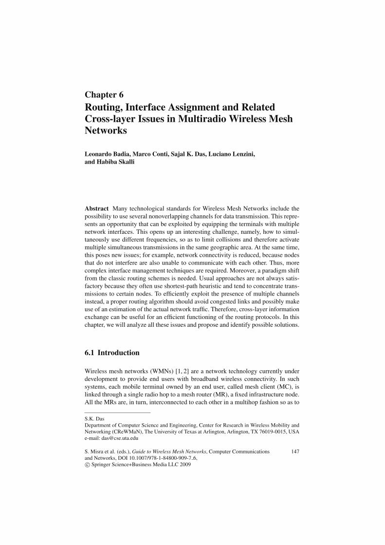
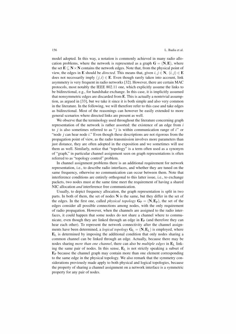
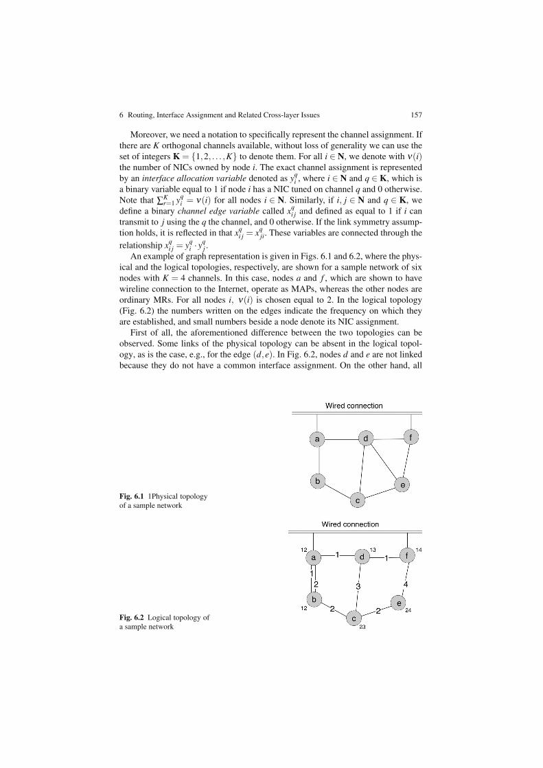
An example of graph representation is given in Figs. 6.1 and 6.2, where the phys-ical and the logical topologies, respectively, are shown for a sample network of sixnodes with K = 4 channels. In this case, nodes a and f , which are shown to havewireline connection to the Internet, operate as MAPs, whereas the other nodes areordinary MRs. For all nodes i, ν(i) is chosen equal to 2. In the logical topology(Fig. 6.2) the numbers written on the edges indicate the frequency on which theyare established, and small numbers beside a node denote its NIC assignment.
First of all, the aforementioned difference between the two topologies can beobserved. Some links of the physical topology can be absent in the logical topol-ogy, as is the case, e.g., for the edge (d,e). In Fig. 6.2, nodes d and e are not linkedbecause they do not have a common interface assignment. On the other hand, all
Fig. 6.1 1Physical topologyof a sample network
Fig. 6.2 Logical topology ofa sample network
158 L. Badia et al.
pairs of nodes in Fig. 6.1 are linked through one edge at most, whereas in Fig. 6.2two edges connect nodes a and b because they share both of their interface assign-ment on channels 1 and 2.
By looking at Fig. 6.2, the interface allocation variables can be derived, for exam-ple y1
a = y2a = 1, y3
a = y4a = 0, or y2
e = y4e = 1, y1
e = y3e = 0. The channel edge variables
are similarly determined, e.g., x1ab = x2
ab = x3cd = 1, x3
ab = x4ab = x1
de = 0.As discussed previously, in most of the investigations related to interface assign-
ment, wireless interference is modeled through the so-called protocol model [22].For our purposes this means that any edge (i, j) ∈ EP is associated with a set J(i, j),called conflicting link set, containing all the edges (x,y) ∈ EP whose activation onthe same frequency than link (i, j) prevents a reliable transmission on it. For practi-cal purposes, we adopt the convention of including also (i, j) in its own conflictinglink set, i.e., (i, j) ∈ J(i, j), which simplifies the notation. The conflict relationshipis mainly because of propagation phenomena; sometimes the conflicting link setsare defined based on simplified models, related for example to the distance betweennodes. It is worth mentioning that this formulation is an abstraction useful for itsconceptual simplicity, and for this reason will be used thereinafter. Yet, from theviewpoint of correctly modeling interference, more realistic descriptions, such asthe so-called physical interference model [22] would be preferable. However, withsome modifications, the reasonings presented in the following could be extendedto alternative interference models as well. A detailed discussion about interferencemodels is out of the scope of the present chapter. The interested reader can foundoverviews on this subject for example in [34, 35].
To instantiate the routing problem in the multichannel environment, we needalso to define for all links (i, j) ∈ EP a parameter c(P)
i j that describes their physicalcapacity, i.e, their nominal data rate (e.g., expressed in Mbps). For completeness,we can introduce a value c(P)
i j = 0 if (i, j) /∈ EP. According to whether edge (i, j) is
reflected in the logical topology also, c(P)i j will be mirrored into a logical capacity
value. Because there are several channels, this latter value depends also on the chan-nel q. Thus, for i, j ∈ N and q ∈ K, we define c(q)
i j that can be larger than zero onlyif xq
i j = 1.Moreover, we denote with γ(s,d) the expected end-to-end traffic to be delivered
from source s to destination d. Typically, in WMN either s or d will coincide withone of the MAPs. We also call λ q
i, j the amount of traffic (involving any pair source-destination) that passes through edge (i, j) over channel q. To put these quantitiesin relationship, it is useful to introduce a binary routing variable called a(m,n),q
i, jdefined as
a(s,d),qi, j =
{1 if traffic from s to d is routed over (i, j) on channel q0 otherwise . (6.1)
These variables will be put in relationship with each other in Sect. 6.5.3, where weuse them to characterize traffic aware routing strategies.
6 Routing, Interface Assignment and Related Cross-layer Issues 159
6.5 Link Load Estimation and Traffic-aware InterfaceAssignment
The task of assigning channels to the available NICs can benefit from the exploita-tion of traffic information. In fact, because the purpose of utilizing multiple channelsat the same time is to decrease interference and promote network parallelism, thisshould be done especially around the most congested links. In this section we dis-cuss possible strategies to retrieve this knowledge and exploit it.
6.5.1 Link Load Estimation
There are different methods for deriving a rough estimate of the expected link traf-fic load. These methods depend on the routing strategy used (e.g., load balancedrouting, multipath routing, shortest path routing, and so on). A possible approachis based on the concept of load criticality [13]. This method assumes perfect loadbalancing across all acceptable paths between each communicating pair of nodes.Let P(s,d) denote the number of loop-free paths between a source-destination pairof nodes (s,d) ∈ N×N, and let Pl(s,d) be the number of them that pass through agiven link � ∈ EP. Then the expected traffic load Φl on link � is calculated as
Φl = ∑(s,d)∈EL
Pl(s,d)P(s,d)
· γ(s,d). (6.2)
This equation implies that the initial expected traffic on a link is the sum of the loadsfrom all acceptable paths, across all possible node pairs, that pass through the link.Because of the assumption of uniform multipath routing, the load that an acceptablepath between a pair of nodes is expected to carry is equal to the expected load of thepair of nodes divided by the total number of acceptable paths between them.
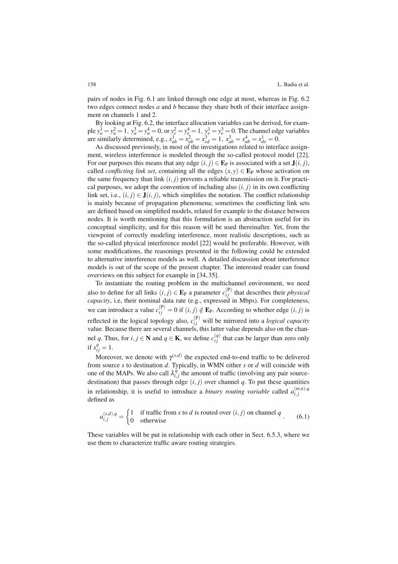
Consider the logical topology as shown in Fig. 6.3 and assume that we have thethree flows reported in Table 6.1.
Fig. 6.3 Multichannel wire-less mesh network
160 L. Badia et al.
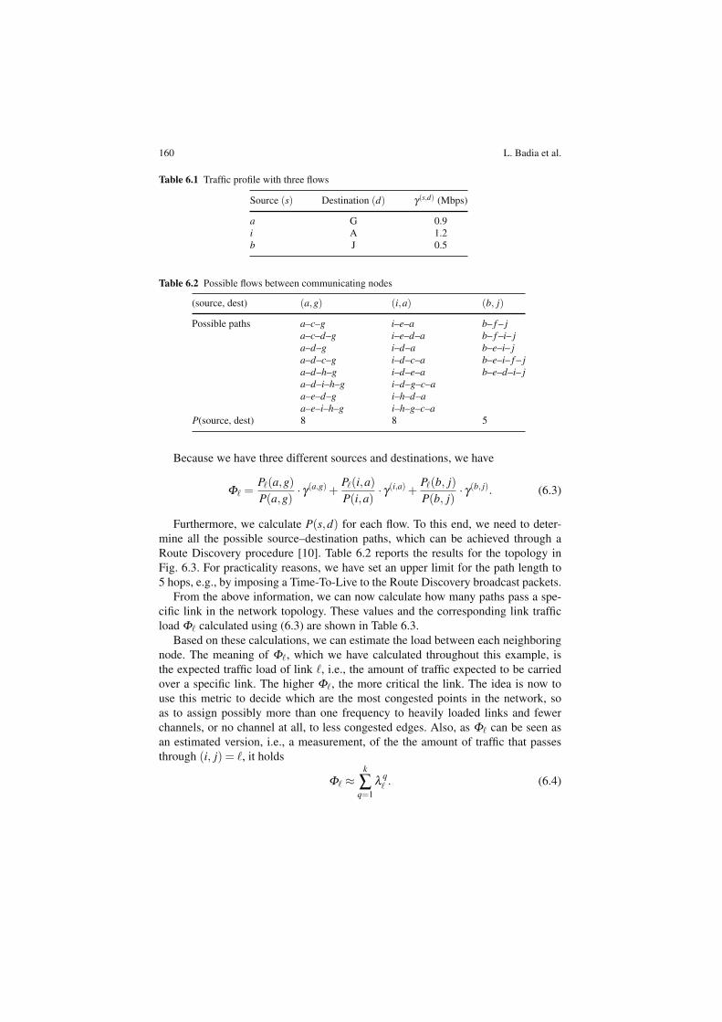
Table 6.1 Traffic profile with three flows
Source (s) Destination (d) γ(s,d) (Mbps)
a G 0.9i A 1.2b J 0.5
Table 6.2 Possible flows between communicating nodes
(source, dest) (a,g) (i,a) (b, j)
Possible paths a–c–g i–e–a b– f – ja–c–d–g i–e–d–a b– f –i– ja–d–g i–d–a b–e–i– ja–d–c–g i–d–c–a b–e–i– f – ja–d–h–g i–d–e–a b–e–d–i– ja–d–i–h–g i–d–g–c–aa–e–d–g i–h–d–aa–e–i–h–g i–h–g–c–a
P(source, dest) 8 8 5
Because we have three different sources and destinations, we have
Φ� =P�(a,g)P(a,g)
· γ(a,g) +P�(i,a)P(i,a)
· γ(i,a) +P�(b, j)P(b, j)
· γ(b, j). (6.3)
Furthermore, we calculate P(s,d) for each flow. To this end, we need to deter-mine all the possible source–destination paths, which can be achieved through aRoute Discovery procedure [10]. Table 6.2 reports the results for the topology inFig. 6.3. For practicality reasons, we have set an upper limit for the path length to5 hops, e.g., by imposing a Time-To-Live to the Route Discovery broadcast packets.
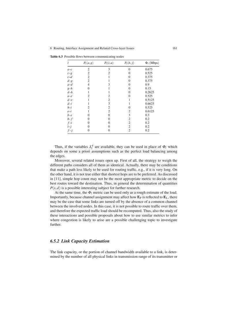
From the above information, we can now calculate how many paths pass a spe-cific link in the network topology. These values and the corresponding link trafficload Φ� calculated using (6.3) are shown in Table 6.3.
Based on these calculations, we can estimate the load between each neighboringnode. The meaning of Φ�, which we have calculated throughout this example, isthe expected traffic load of link �, i.e., the amount of traffic expected to be carriedover a specific link. The higher Φ�, the more critical the link. The idea is now touse this metric to decide which are the most congested points in the network, soas to assign possibly more than one frequency to heavily loaded links and fewerchannels, or no channel at all, to less congested edges. Also, as Φ� can be seen asan estimated version, i.e., a measurement, of the the amount of traffic that passesthrough (i, j) = �, it holds
Φ� ≈k
∑q=1
λ q� . (6.4)
6 Routing, Interface Assignment and Related Cross-layer Issues 161
Table 6.3 Possible flows between communicating nodes
� P�(a,g) P�(i,a) P�(b, j) Φ� (Mbps)
a–c 2 3 0 0.675c–g 2 2 0 0.525c–d 2 1 0 0.375d–g 2 1 0 0.375a–d 4 3 0 0.9g–h 0 1 0 0.15d–h 1 1 0 0.2625a–e 2 2 0 0.525d–e 1 2 1 0.5125d–i 1 3 1 0.6625h–i 2 2 0 0.525e–i 1 2 2 0.6125b–e 0 0 3 0.3b– f 0 0 2 0.2f –i 0 0 2 0.2i– j 0 0 2 0.2f – j 0 0 2 0.2
Thus, if the variables λ q� are available, they can be used in place of Φ� which
depends on some a priori assumptions such as the perfect load balancing amongthe edges.
Moreover, several related issues open up. First of all, the strategy to weigh thedifferent paths considers all of them as identical. Actually, there may be conditionsthat make a path less likely to be used for routing traffic, e.g., if it is very long. Onthe other hand, it is not true either that shortest hops are to be preferred. As discussedin [11], simple hop count may not be the most appropriate metric to decide on thebest routes toward the destination. Thus, in general the determination of quantitiesP(s,d) is a possible interesting subject for further research.
At the same time, the Φ� metric can be used only as a rough estimate of the load.Importantly, because channel assignment may affect how EP is reflected to EL, theremay be the case that some links are turned off by the absence of a common channelbetween the involved nodes. In this case, it is not possible to route traffic over them,and therefore the expected traffic load should be recomputed. Thus, also the study ofthese interactions and possible proposals about how to use similar metrics to inferwhere congestion is likely to arise are a possible challenging topic to investigatefurther.
6.5.2 Link Capacity Estimation
The link capacity, or the portion of channel bandwidth available to a link, is deter-mined by the number of all physical links in transmission range of its transmitter or
162 L. Badia et al.
its receiver, i.e., in its conflicting link set, that are also assigned to the same channel.Obviously, the exact short-term instantaneous bandwidth available to each link isdynamic and continuously changing depending on several propagation and interfer-ence phenomena [13]. The goal here is to derive an approximation of the long-termbandwidth share available. Thus, the capacity b(q)
i j assigned to link (i, j) on channelq can be obtained using the following equation:
b(q)i j =
λ qi j
∑(x,y)∈J(i, j)
λ qxy· c(q)
i j . (6.5)
Note that if ν(i) = ν , constant for all the nodes,
K
∑q=1
b(q)i j ≈
Φi jν · c(P)i j
∑(x,y)∈J(i, j)
Φxy. (6.6)
In other words, the capacity share available to a link is approximately proportionalto its expected load.
6.5.3 Traffic-Aware Joint Interface Assignment and Routing
Giving the preliminaries defined in Sect. 6.4 and the results reported previously,we may specify relationships among the variables that can be used, for example, inan LP context as done by [12]. We stress the important aspect that a comprehen-sive framework includes channel assignment (represented by variables yq
i and xqi j),
routing variables a(m,n),qi, j , and finally traffic information (variables γ(s,d)). Thus, it is
appropriate to refer to the resulting model as a traffic-aware joint interface assign-ment and routing. We focus on the model only, whereas the solution techniques areout of the scope of the present analysis. Only, we remark here that the model is rathergeneral and can be solved in a plethora of ways, including exact and approximate,centralized and distributed ones.
The variables of the model are related as per the following relationship, whichcan be seen as LP constraints. The aggregate traffic on a given link depends on therouting variables and the traffic requirements, so that
λ qi, j = ∑
(s,d)∈N×Na(s,d),q
i, j γ(s,d). (6.7)
The effective capacity c(q)i j of link (i, j) on any channel q cannot exceed the nominal
capacity c(P)i j and it is zero if i and j do not share channel assignment q. Thus,
c(q)i j = xq
i jc(P)i j . (6.8)
6 Routing, Interface Assignment and Related Cross-layer Issues 163
Moreover, the aggregate traffic λ qi, j must be less than c(q)
i j . Actually, in [12] it isproposed to strengthen this constraint by including a parameter Λ ≤ 1. The motiva-tion is that perfect capacity sharing among all interfering links is not true in prac-tice. Thus, this constraint may be ineffective because it overestimates the effectivecapacity. Obviously, this is just an artifice and other solutions to cope with this prob-lem are possible as well. Then, we impose
λ qi, j ≤ Λc(q)
i j . (6.9)
Finally, we impose a constraint describing conservation of the flows, i.e.,
∑j∈N
(i, j)∈EP
K
∑q=1
a(s,d),qi, j γ(s,d)− ∑
j∈N(i, j)∈EP
K
∑q=1
a(s,d),qj,i γ(s,d) =
⎧⎨
⎩
γ(s,d) if s = i−γ(s,d) if d = i
0 otherwise. (6.10)
At this point, several metrics can be chosen as the metric to optimize. For exam-ple, following again [12], we can choose to minimize the ratio between load andavailable capacity share on the most congested link. This implies to optimize theutilization of the most congested link and results in the following objective:
min(i, j)∈EP
maxxq
i j=1
λ qi, j
b(q)i j
. (6.11)
This somehow determines a performance bound in terms of capacity, which is inde-pendent of the absolute values of load requirements γ(s,d). In fact, they can berescaled until constraint (6.9) is violated. Therefore, the most congested link givesthe capacity bottleneck for the throughput of the whole network. Of course, otherobjectives are possible as well, for example also introducing fairness considera-tions. Finally, once the objective function has been identified, the problem can beapproached by both LP optimization frameworks and heuristic techniques, and bothin a centralized and a distributed manner. The choice of the specific technique to usemostly relates to general design issues such as the computational capability of theterminals.
6.6 Directions for Future Research
Even though many algorithms have been proposed in this context, the design of effi-cient techniques for interface assignment and routing in multiradio WMN is still anopen issue. In the previous sections, we have identified certain possible enhance-ments to the usual routing and channel assignment metrics. However, the researchcommunity need also to face the issue of implementing these techniques within anoptimization framework.
164 L. Badia et al.
In this context, two related problems appear to be of primary importance. First ofall, scalability is known as the main challenge not only, e.g., for routing problems,but also for any resource allocation issue in WMNs. Because the impact of WMNis expected to be very pervasive, and it is often assumed that at least hundreds ofnodes can be part of the network, we must acknowledge a difficulty in identifyingpractical algorithms for large networks. This involves the trade-off between exactsolutions, whose computational complexity may explode as the number of variables(nodes times interfaces) can be extremely high, and heuristic techniques, which canoften manage WMNs with many nodes but are very difficult to validate, because itis hard to tell how far from optimality they are. Moreover, another problem, whichstill relates to scalability issues, is to identify where the source of the computationalcapabilities is located, i.e., how to coordinate the mesh routers to achieve an efficientallocation. In this sense, another trade-off is involved, namely, centralized vs. dis-tributed management. Centralized solutions can work only if the MAP is powerfulenough and the number of nodes is not high, so that global awareness about nodesand channels is possible. Otherwise, distributed solutions should be sought. How-ever, these techniques do not always achieve the same performance than centralizedmanagement.
For these reasons, it is key that new research on the topics of routing and interfaceassignment in multiradio WMNs involves a significant effort to determine efficientoptimization techniques with low computational complexity, and also distributedimplementations that approach the performance of centralized solutions. Moreover,we recognize the study of clustered networks [36] as a possible application of theseprinciples. Aggregating terminals in small clusters that are easy to manage allow adramatic reduction of the computational complexity. If the network partitioning isperformend efficiently, the solution found is still close to the optimal. Finally, clus-tered managements of WMNs can be seen as an intermediate solution between thefully distributed (but also inefficient) and the fully centralized (with acute computa-tional problems) approaches.
6.7 Conclusions
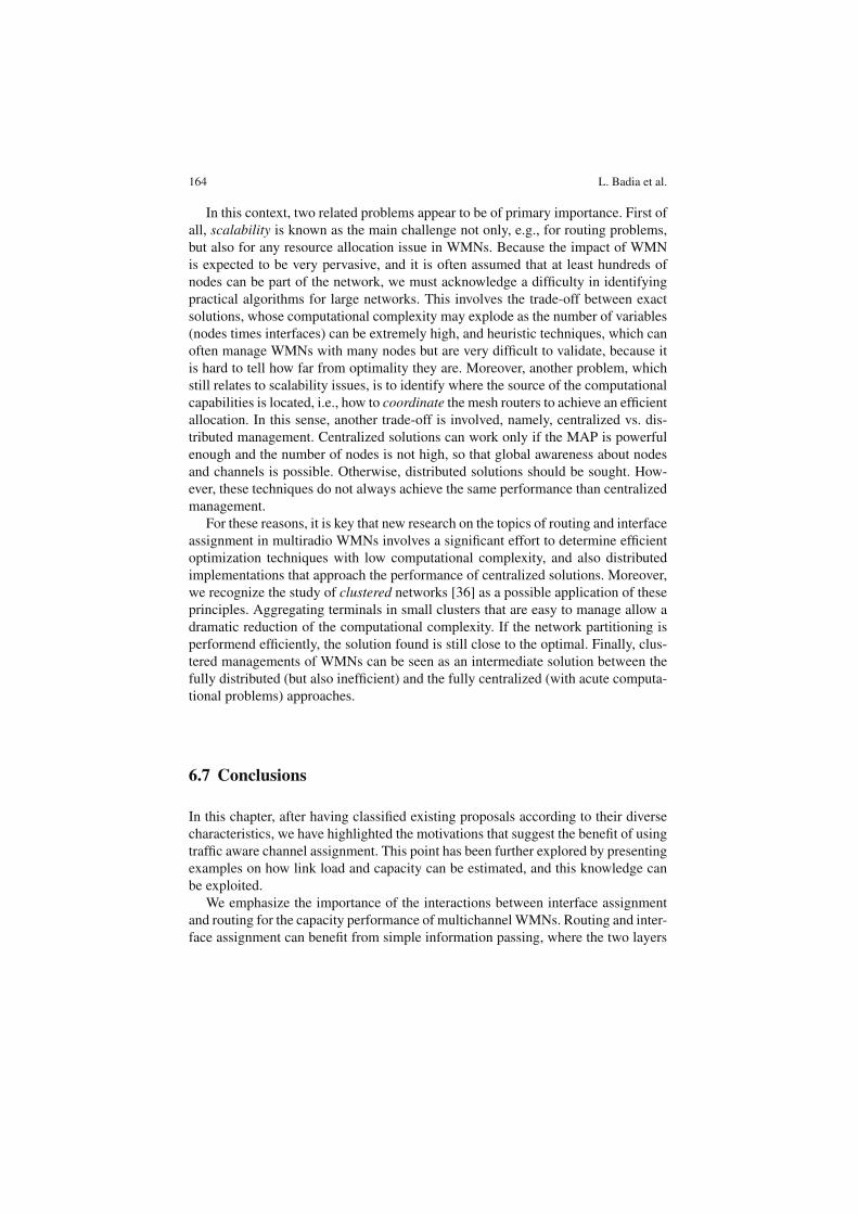
In this chapter, after having classified existing proposals according to their diversecharacteristics, we have highlighted the motivations that suggest the benefit of usingtraffic aware channel assignment. This point has been further explored by presentingexamples on how link load and capacity can be estimated, and this knowledge canbe exploited.
We emphasize the importance of the interactions between interface assignmentand routing for the capacity performance of multichannel WMNs. Routing and inter-face assignment can benefit from simple information passing, where the two layers
6 Routing, Interface Assignment and Related Cross-layer Issues 165
are still separated but cooperating. Moreover, if the terminal capabilities allow forit, one can also think of merging together the related strategies with a cross-layerapproach.
To sum up, from a general viewpoint there are strong expectations about multira-dio WMNs providing end users with high network capacity. However, routing andinterface assignment, require a careful, and possibly joint, investigation because oftheir tight interdependencies. Traffic aware algorithms, which offer the opportunityto turn this relationship to an advantage, appear as very promising to make this goaleasier to reach.
6.8 Terminologies
1. Wireless mesh network (WMN). It is a communication network, where clientsare connected via radio to routers that are in turn interconnected via multi-hop wireless links. Its structure is entirely wireless, thus making WMNs espe-cially applicable where cable deployment is difficult or too expensive. Becausethe wireless medium is intrinsically broadcast, the radio nodes belonging tothe WMN need special procedures to work in harmony with each other andenable dedicated communications.
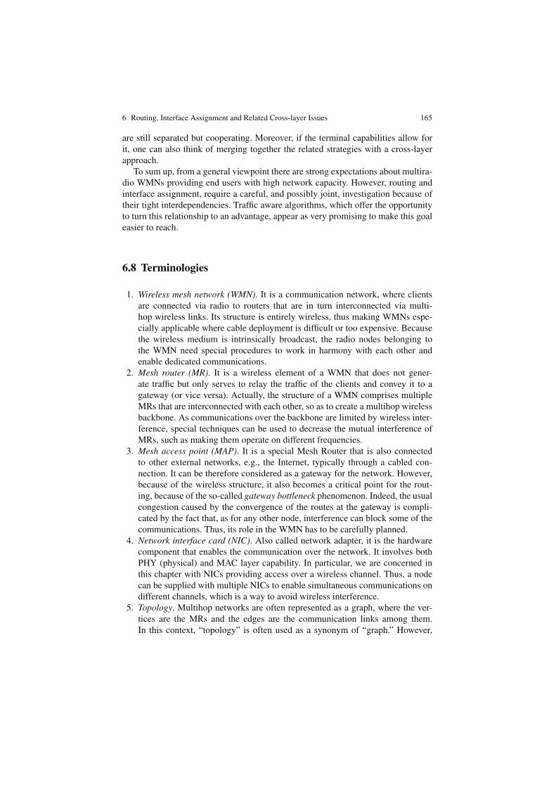
2. Mesh router (MR). It is a wireless element of a WMN that does not gener-ate traffic but only serves to relay the traffic of the clients and convey it to agateway (or vice versa). Actually, the structure of a WMN comprises multipleMRs that are interconnected with each other, so as to create a multihop wirelessbackbone. As communications over the backbone are limited by wireless inter-ference, special techniques can be used to decrease the mutual interference ofMRs, such as making them operate on different frequencies.
3. Mesh access point (MAP). It is a special Mesh Router that is also connectedto other external networks, e.g., the Internet, typically through a cabled con-nection. It can be therefore considered as a gateway for the network. However,because of the wireless structure, it also becomes a critical point for the rout-ing, because of the so-called gateway bottleneck phenomenon. Indeed, the usualcongestion caused by the convergence of the routes at the gateway is compli-cated by the fact that, as for any other node, interference can block some of thecommunications. Thus, its role in the WMN has to be carefully planned.
4. Network interface card (NIC). Also called network adapter, it is the hardwarecomponent that enables the communication over the network. It involves bothPHY (physical) and MAC layer capability. In particular, we are concerned inthis chapter with NICs providing access over a wireless channel. Thus, a nodecan be supplied with multiple NICs to enable simultaneous communications ondifferent channels, which is a way to avoid wireless interference.
5. Topology. Multihop networks are often represented as a graph, where the ver-tices are the MRs and the edges are the communication links among them.In this context, “topology” is often used as a synonym of “graph.” However,
166 L. Badia et al.
when multiple frequencies are introduced, different graph representations (andtherefore, different topologies) need to be considered, where the set of vertices,i.e., the MRs, is always the same but the set of edges changes.
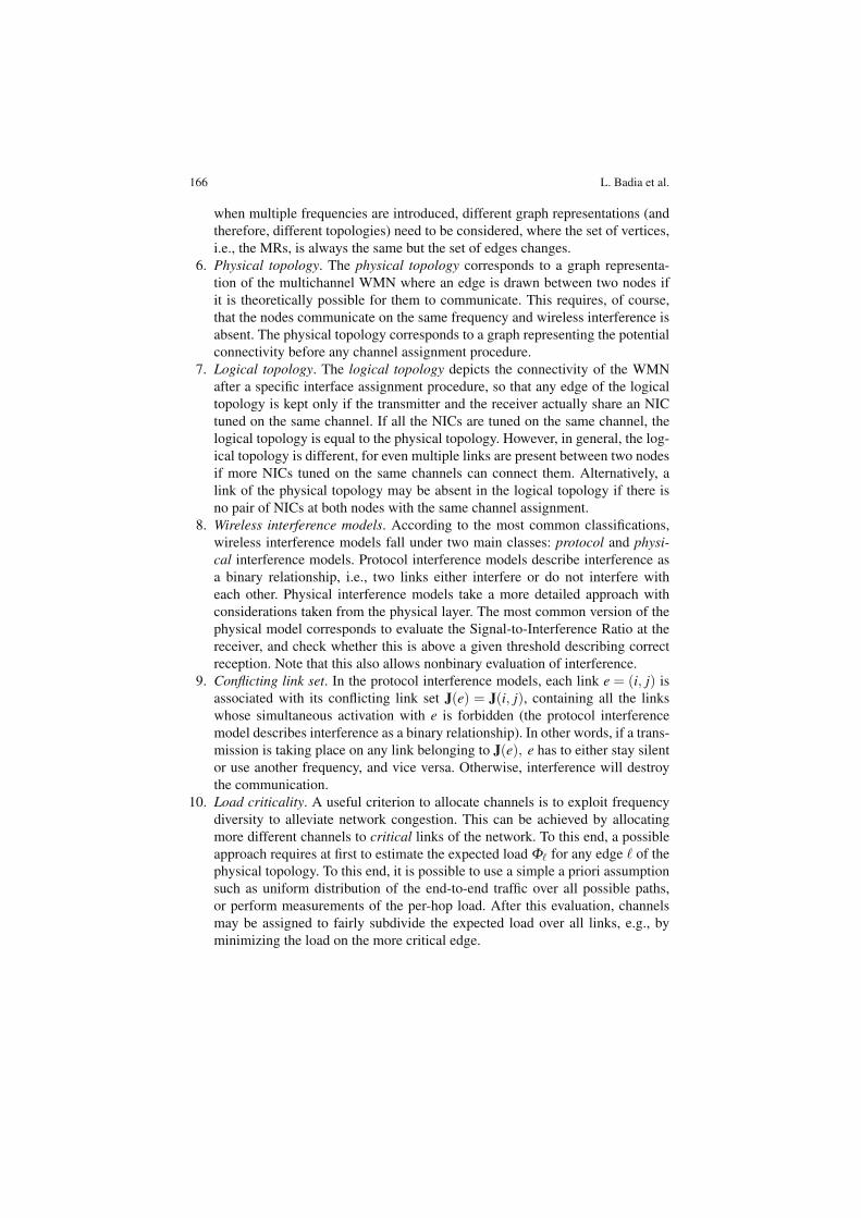
6. Physical topology. The physical topology corresponds to a graph representa-tion of the multichannel WMN where an edge is drawn between two nodes ifit is theoretically possible for them to communicate. This requires, of course,that the nodes communicate on the same frequency and wireless interference isabsent. The physical topology corresponds to a graph representing the potentialconnectivity before any channel assignment procedure.
7. Logical topology. The logical topology depicts the connectivity of the WMNafter a specific interface assignment procedure, so that any edge of the logicaltopology is kept only if the transmitter and the receiver actually share an NICtuned on the same channel. If all the NICs are tuned on the same channel, thelogical topology is equal to the physical topology. However, in general, the log-ical topology is different, for even multiple links are present between two nodesif more NICs tuned on the same channels can connect them. Alternatively, alink of the physical topology may be absent in the logical topology if there isno pair of NICs at both nodes with the same channel assignment.
8. Wireless interference models. According to the most common classifications,wireless interference models fall under two main classes: protocol and physi-cal interference models. Protocol interference models describe interference asa binary relationship, i.e., two links either interfere or do not interfere witheach other. Physical interference models take a more detailed approach withconsiderations taken from the physical layer. The most common version of thephysical model corresponds to evaluate the Signal-to-Interference Ratio at thereceiver, and check whether this is above a given threshold describing correctreception. Note that this also allows nonbinary evaluation of interference.
9. Conflicting link set. In the protocol interference models, each link e = (i, j) isassociated with its conflicting link set J(e) = J(i, j), containing all the linkswhose simultaneous activation with e is forbidden (the protocol interferencemodel describes interference as a binary relationship). In other words, if a trans-mission is taking place on any link belonging to J(e), e has to either stay silentor use another frequency, and vice versa. Otherwise, interference will destroythe communication.
10. Load criticality. A useful criterion to allocate channels is to exploit frequencydiversity to alleviate network congestion. This can be achieved by allocatingmore different channels to critical links of the network. To this end, a possibleapproach requires at first to estimate the expected load Φ� for any edge � of thephysical topology. To this end, it is possible to use a simple a priori assumptionsuch as uniform distribution of the end-to-end traffic over all possible paths,or perform measurements of the per-hop load. After this evaluation, channelsmay be assigned to fairly subdivide the expected load over all links, e.g., byminimizing the load on the more critical edge.
6 Routing, Interface Assignment and Related Cross-layer Issues 167
6.9 Questions
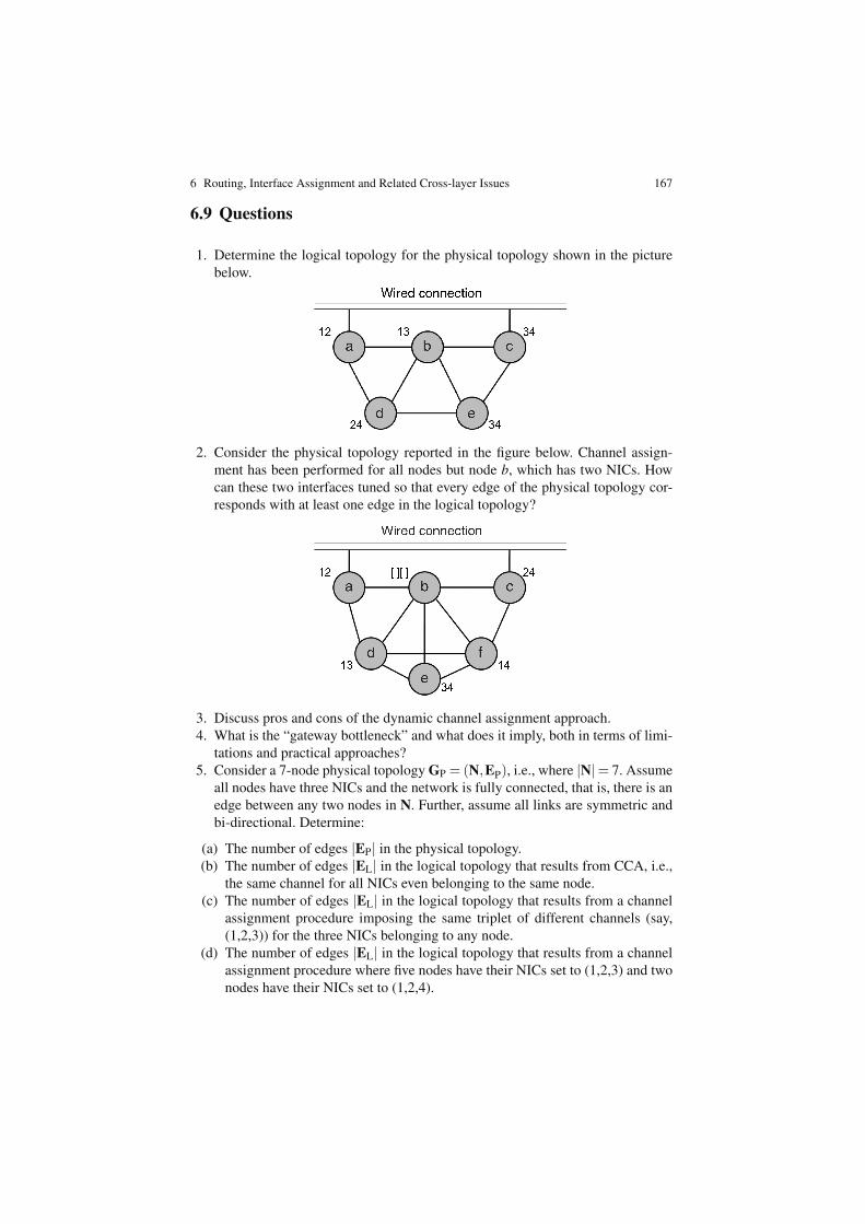
1. Determine the logical topology for the physical topology shown in the picturebelow.
2. Consider the physical topology reported in the figure below. Channel assign-ment has been performed for all nodes but node b, which has two NICs. Howcan these two interfaces tuned so that every edge of the physical topology cor-responds with at least one edge in the logical topology?
3. Discuss pros and cons of the dynamic channel assignment approach.4. What is the “gateway bottleneck” and what does it imply, both in terms of limi-
tations and practical approaches?5. Consider a 7-node physical topology GP = (N,EP), i.e., where |N|= 7. Assume
all nodes have three NICs and the network is fully connected, that is, there is anedge between any two nodes in N. Further, assume all links are symmetric andbi-directional. Determine:
(a) The number of edges |EP| in the physical topology.(b) The number of edges |EL| in the logical topology that results from CCA, i.e.,
the same channel for all NICs even belonging to the same node.(c) The number of edges |EL| in the logical topology that results from a channel
assignment procedure imposing the same triplet of different channels (say,(1,2,3)) for the three NICs belonging to any node.
(d) The number of edges |EL| in the logical topology that results from a channelassignment procedure where five nodes have their NICs set to (1,2,3) and twonodes have their NICs set to (1,2,4).
168 L. Badia et al.
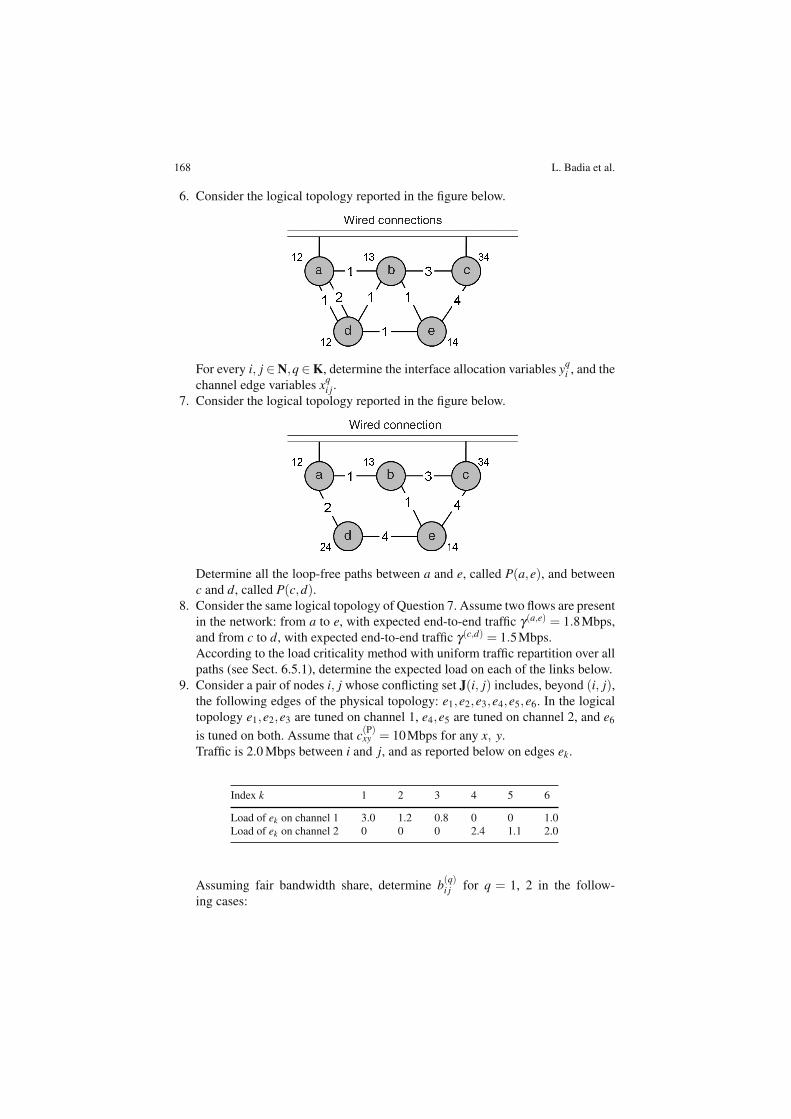
6. Consider the logical topology reported in the figure below.
For every i, j ∈ N,q ∈ K, determine the interface allocation variables yqi , and the
channel edge variables xqi j.
7. Consider the logical topology reported in the figure below.
Determine all the loop-free paths between a and e, called P(a,e), and betweenc and d, called P(c,d).
8. Consider the same logical topology of Question 7. Assume two flows are presentin the network: from a to e, with expected end-to-end traffic γ(a,e) = 1.8Mbps,and from c to d, with expected end-to-end traffic γ(c,d) = 1.5Mbps.According to the load criticality method with uniform traffic repartition over allpaths (see Sect. 6.5.1), determine the expected load on each of the links below.
9. Consider a pair of nodes i, j whose conflicting set J(i, j) includes, beyond (i, j),the following edges of the physical topology: e1,e2,e3,e4,e5,e6. In the logicaltopology e1,e2,e3 are tuned on channel 1, e4,e5 are tuned on channel 2, and e6
is tuned on both. Assume that c(P)xy = 10Mbps for any x, y.
Traffic is 2.0 Mbps between i and j, and as reported below on edges ek.
Index k 1 2 3 4 5 6
Load of ek on channel 1 3.0 1.2 0.8 0 0 1.0Load of ek on channel 2 0 0 0 2.4 1.1 2.0
Assuming fair bandwidth share, determine b(q)i j for q = 1, 2 in the follow-
ing cases:
6 Routing, Interface Assignment and Related Cross-layer Issues 169
(a) Nodes i and j share one NIC assignment on channel 1.(b) Nodes i and j share one NIC assignment on channel 2.(c) Nodes i and j share two NIC assignments on both channels 1 and 2, and the
traffic is equally split between the resulting two links in the logical topology.
10. Consider the same setup of Question 9 (point (c)) but now assume we want totake the objective of optimal utilization into account, as per (6.11). Assume link(i, j) is the most critical of the network. How should its traffic be split betweenchannels 1 and 2?
References
1. I.F. Akyildiz, X. Wang, and W. Wang, Wireless mesh networks: a survey. Comput. Networks(Elsevier) 47(4): 445–487 (2005).
2. R. Bruno, M. Conti, and E. Gregori, Mesh networks: commodity multihop ad hoc networks.IEEE Commun. 43(3): 123–131 (2005).
3. X. Hong, K. Xu, and M. Gerla, Scalable routing protocols for mobile ad hoc networks. IEEENetwork 16(4): 11–21 (2002).
4. Wireless LAN medium access control (MAC) and physical layer (PHY) specification”, IEEEStd. 802.11, (1997).
5. S. Basagni, M. Conti, S. Giordano, and I. Stojmenovı́c, Eds., Mobile Ad Hoc Networking.IEEE/Wiley, New York, NY (2004).
6. A. Mishra, V. Shrivastava, S. Banerjee, and W. Arbaugh, Partially overlapped channels notconsidered harmful. Proc. ACM SIGMetrics Perform., 63–74 (2006).
7. D. Banerjee and B. Mukherjee, A practical approach for routing and wavelength assignmentin largewavelength-routed optical networks. IEEE J. Select. Areas Commun. 14(5): 903–908 (1996).
8. P. Kyasanur and N.H. Vaidya, Capacity of multichannel wireless networks: impact of numberof channels and interfaces. Proc. ACM MobiCom, 43–57 (2005).
9. D.B. Johnson, D.A. Maltz, and J. Broch, DSR: The dynamic source routing protocol for mul-tihop wireless ad hoc networks. In: Perkins C.E. (Ed.) Ad Hoc Networking. Addison-Wesley,London, Chap. 5, 139–172 (2001).
10. C. Perkins, E. Belding-Royer, and S.R. Das Ad Hoc On-Demand Distance Vector (AODV)Routing. IETF RFC 3561 (2003).
11. R. Draves, J. Padhye, and B. Zill Routing in multi-radio, multi-hop wireless mesh networks.Proc. ACM MobiCom, 114–128 (2004).
12. A.H. Mohsenian Rad and V.W.S. Wong Joint optimal channel allocation, interface assignment,and MAC design for multi-channel wireless mesh networks. Proc. IEEE INFOCOM, 1469–1477 (2007).
13. A. Raniwala, K. Gopalan, and T. Chiueh Centralized channel assignment and routing algo-rithms for multi-channel wireless mesh networks. ACM Mobile Comput. Commun. Rev.(MC2R) 8(2): 50–65 (2004).
14. I. Katzela and M. Naghshineh Channel assignment schemes for cellular mobile telecommuni-cationsystems: a comprehensive survey. IEEE Pers. Commun. 3(3): 10–31 (1996).
15. A.H. Mohsenian Rad and V.W.S. Wong, Partially overlapped channel assignment for multi-channel wireless mesh networks. Proc. IEEE ICC, 3770–3775 (2007).
16. I. Cidon and M. Sidi, Distributed assignment algorithms for multihop packet radionetworks.IEEE Trans. Comput. 38(10): 1353–1361, (1989).
17. P. Kyasanur and N.H. Vaidya, Routing and interface assignment in multi-channel multi-interface wireless networks. Proc. IEEE WCNC 4: 2051–2056 (2005).
170 L. Badia et al.
18. M. Alicherry, R. Bhatia, and L.E. Li, Joint channel assignment and routing for throughputoptimization in multiradio wireless mesh networks. IEEE J. Select. Areas Commun. 24(11):1960–1971 (2006).
19. Y.Y. Chen, S.C. Liu, and C. Chen, Channel assignment and routing for multi-channel wirelessmesh networks using simulated annealing. Proc. of IEEE Globecom, 1–5 (2006).
20. X. Meng, K. Tan, and Q. Zhang, Joint routing and channel assignment in multi-radio wirelessmesh networks. Proc. IEEE ICC 8: 3596–3601 (2006).
21. M. Kodialam and T. Nandagopal, Characterizing the capacity region in multi-radio multi-channel wireless mesh networks. Proc. ACM MobiCom, 73–87 (2005).
22. P. Gupta and P.R. Kumar, The capacity of wireless networks. IEEE Trans. Inform. Theory46(8): 388–404 (2000).
23. G. Brar, D. Blough, and P. Santi, Computationally efficient scheduling with the physical inter-ference model for throughput improvement in wireless mesh networks. Proc. ACM MobiCom,2–13 (2006).
24. S. Kirkpatrick, C.D. Gelatt, and M.P. Vecchi, Optimization by simulated annealing. Science220: 671–680 (1983).
25. M.K. Marina and S.R. Das A topology control approach for utilizing multiple channels inmulti-radio wireless mesh networks. Proc. Int. Conf. Broadband Netw., 381–390 (2005).
26. H. Skalli, S. Ghosh, S.K. Das, L. Lenzini, and M. Conti Channel assignment strategies formulti-radio wireless mesh networks: issues and solutions. IEEE Commun. Mag. 45(11): 86–95 (2007).
27. J. So and N.H. Vaidya Multi-channel MAC for ad hoc networks: handling multi-channel hid-den terminals using a single transceiver. Proc. ACM MobiHoc, 222–233 (2004).
28. P. Bahl, R. Chandra, and J. Dunagan, SSCH: Slotted seeded channel hopping for capac-ity improvement in IEEE 802.11 ad-hoc wireless networks. Proc. ACM Mobicom, 216–230(2004).
29. A. Raniwala and T. Chiueh, Architecture and algorithms for an IEEE 802.11-based multi-channel wireless mesh network. Proc. IEEE INFOCOM, 2223–2234 (2005).
30. K. Ramachandran, K. Almeroth, E. Belding-Royer, and M. Buddhikot, Interference awarechannel assignment in multi-radio wireless mesh networks. Proc. IEEE INFOCOM, 1–12(2006).
31. J. Jun and M.L. Sichitiu, The nominal capacity of wireless mesh networks. IEEE WirelessCommun. 10(5): 8–14 (2003).
32. D. Kotz, C. Newport, R.S. Gray, J. Liu, Y. Yuan, and C. Elliott, Experimental evaluation ofwireless simulation assumptions. Proc. ACM MSWiM, 78–82 (2004).
33. M.K. Marina and S.R. Das, Routing performance in the presence of unidirectional links inmultihop wireless networks. Proc. ACM MobiHoc, 12–23 (2002).
34. L. Badia, A. Erta, L. Lenzini, and M. Zorzi, A general interference-aware framework for jointrouting and link scheduling in wireless mesh networks. IEEE Netw. 22(1): 32–38 (2008).
35. A. Iyer, C. Rosenberg, and A. Karnik, What is the right model for wireless channel interfer-ence?. Proc. Qshine, No. 2, invited paper (2006).
36. L. Badia, N. Bui, M. Miozzo, M. Rossi, and M. Zorzi, On the exploitation of user aggregationstrategies in heterogeneous wireless networks. Proc. of the 11th IEEE Int. Workshop CAMAD,8–15 (2007).