Embed Size (px)
Citation preview

TRAFFIC DESIGN MANUAL 6-1 MARCH 2012 CHAPTER 6 – SIGNING AND PAVEMENT MARKINGS
CHAPTER 6 SIGNING AND PAVEMENT MARKINGS
6.0 GENERAL
The designer is responsible for ensuring signing and/or pavement marking projects comply with the following documents:
Manual on Uniform Traffic Control Devices (MUTCD). The MUTCD is the obligatory guide for signing and pavement marking. It is published by Federal Highway Administration (FHWA) in conjunction with the Institute of Transportation Engineers (ITE), American Traffic Safety Services Association (ATSSA), and American Association of State Highway and Transportation Officials (AASHTO). The designer should review the FHWA MUTCD website for the latest edition of the MUTCD along with any interim updates and compliance dates.
Standard Highway Signs, FHWA. This document contains detailed drawings of all standard highway signs in addition to standard alphabets, symbols, and arrows. Each sign is identified by a unique designation. Signs not included in the Standard Highway Signs or in the TDOT Supplement to Standard Highway Signs must be detailed in the plans.
TDOT Supplement to Standard Highway Signs. This document provides detailed drawings for signs and symbols that are applicable to Tennessee, but are not addressed in the MUTCD.
Standard Specifications for Structural Supports for Highway Signs, Luminaires and Traffic Signals, AASHTO. This document provides the design criteria for the structural design of highway sign supports, luminaires, and traffic signals.
Roadway Standard Drawings. These standards are composed of a number of standard drawings or indexes that address specific situations that occur on a large majority of construction projects.
TDOT Standard Specifications for Road and Bridge Construction (Standard Specifications). The Standard Specifications are the requirements adopted by the Department for work methods, materials, and basis of payment used in construction. The Standard Specifications are intended for general and repetitive use. They provide Department criteria for the scope of work, control of work, control of materials, legal regulations and responsibilities to the public, contract prosecution and progress, and measurement and payment of contract items.
TDOT Roadway Design Guidelines. These Guidelines establish uniform procedures for roadway design activities within the Department and provide guidance in the preparation of roadway plans and estimates.
6.1 SIGNING
All regulatory and warning signs shall meet the design and installation requirements of the MUTCD. Effective signing provides clear information and instruction to motor vehicle operators, pedestrians, and bicyclists. Properly installed signing facilitates legal, safe, and orderly progress on public roadways.

TRAFFIC DESIGN MANUAL 6-2 MARCH 2012 CHAPTER 6 – SIGNING AND PAVEMENT MARKINGS
6.1.1 MUTCD
The guidance provided in the MUTCD is divided into four categories — standard, guidance, option, and support. These categories are used to determine the appropriate application for the various traffic control devices. Where applicable, the designer is required to meet the criteria presented in the “Standard” and “Guidance” categories. These categories are sometimes modified by the “Option” category. Where TDOT has elected to adopt the “Option” condition, the designer will be required to meet the “Option” criteria presented in the MUTCD. “Support” statements provide additional information on the topic and do not convey any degree of mandate, recommendation, authorization, prohibition, or enforceable condition. The designer should review the “Support” statements for a better understanding of when and where to use the traffic control device.
6.1.2 Application
Signs should be used only where justified by engineering judgment or studies, as provided in Section 1A.09 of the MUTCD. Results from traffic engineering studies of physical and traffic factors should indicate the locations where signs are deemed necessary or desirable. Roadway geometric design and sign application should be coordinated so that signing can be effectively placed to give the road user any necessary regulatory, warning, guidance, and other information.1
6.1.3 Sign Layouts
The MUTCD, TDOT Supplement to Standard Highway Signs, and TDOT Roadway Standard Drawings provide guidance on the placement of regulatory signs, warning signs, guide signs, information signs, service signs, and other signs used in Tennessee.
6.1.4 Conventional Highways (Non-Access Controlled) Signs
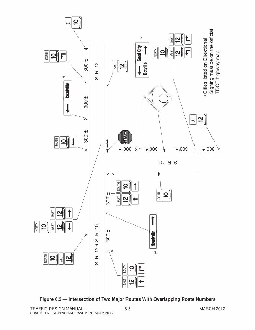
6.1.4.1 Directional and Route Signing at Intersections
The following figures illustrate typical sign assemblies for directional assemblies and route signing at intersections:
1. Figure 6.1 — Intersection of Two Major Routes (4-Way Intersection) 2. Figure 6.2 — Intersection of Two Major Routes (3-Way Intersection) 3. Figure 6.3 — Intersection of Two Major Routes with Overlapping Route
Numbers 4. Figure 6.4 — 4-Way Intersection Route Signing with Scenic (Bird) Route 5. Figure 6.5 — 3-Way Intersection Route Signing with Scenic (Bird) Route 6. Figure 6.6 — 3-Way Intersection Route Signing with Scenic (Bird) Route
with Overlapping Route Numbers
1 2009 MUTCD, FHWA, Section 2A.03 “Standardization of Application”

TRAFFIC DESIGN MANUAL 6-3 MARCH 2012 CHAPTER 6 – SIGNING AND PAVEMENT MARKINGS
Figure 6.1 — Intersection of Two Major Routes (4-Way Intersections)

TRAFFIC DESIGN MANUAL 6-4 MARCH 2012 CHAPTER 6 – SIGNING AND PAVEMENT MARKINGS
Figure 6.2 — Intersection of Two Major Routes (3-Way Intersections)
TRAFFIC DESIGN MANUAL 6-5 MARCH 2012 CHAPTER 6 – SIGNING AND PAVEMENT MARKINGS
Figure 6.3 — Intersection of Two Major Routes With Overlapping Route Numbers

TRAFFIC DESIGN MANUAL 6-6 MARCH 2012 CHAPTER 6 – SIGNING AND PAVEMENT MARKINGS
Figure 6.4 — 4-Way Intersection Route Signing With a Scenic (Bird) Route

TRAFFIC DESIGN MANUAL 6-7 MARCH 2012 CHAPTER 6 – SIGNING AND PAVEMENT MARKINGS
Figure 6.5 — 3-Way Intersection Route Signing With a Scenic (Bird) Route

TRAFFIC DESIGN MANUAL 6-8 MARCH 2012 CHAPTER 6 – SIGNING AND PAVEMENT MARKINGS
Figure 6.6 — 3-Way Intersection Route Signing With a Scenic (Bird) Route With Overlapping Route Numbers
TRAFFIC DESIGN MANUAL 6-9 MARCH 2012 CHAPTER 6 – SIGNING AND PAVEMENT MARKINGS
6.1.4.2 One-Way and Wrong-Way Signing at Median Crossovers
ONE WAY signs shall be used to denote streets where only one direction of traffic is allowed.
When installed, they should be placed on the near right and far left corners of the intersection.
ONE WAY signs are not required for divided streets with a median width of less than 30 feet.
The following figures illustrate typical ONE-Way and WRONG-WAY signing at median crossovers:
1. Figure 6.7 — Crossroad Signing, Medians less than 30 feet, One-Way and Wrong-Way Signing
2. Figure 6.8 — Signalized Intersection, Medians less than 30 feet, One-Way and Wrong-Way Signing
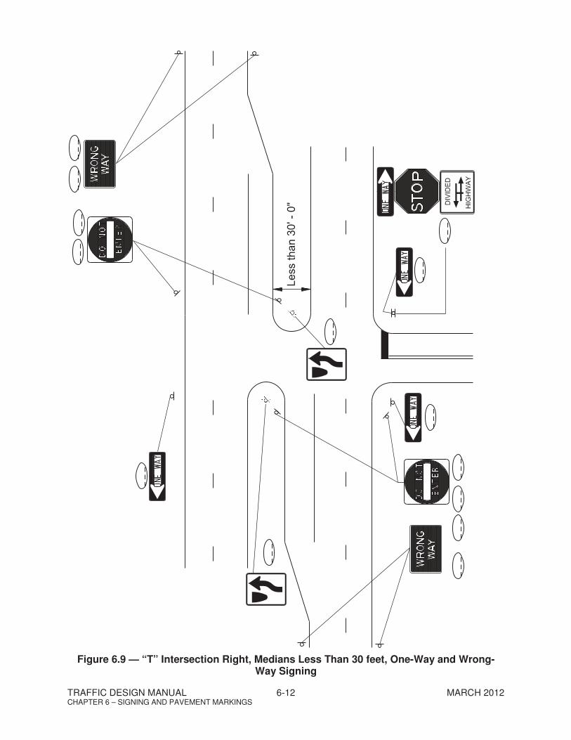
3. Figure 6.9 — “T” Intersection Right, Medians less than 30 feet, One-Way and Wrong-Way Signing
4. Figure 6.10 — “T” Intersection Left, Medians less than 30 feet, One-Way and Wrong-Way Signing
5. Figure 6.11 — Median Crossover, Medians less than 30 feet, One-Way and Wrong-Way Signing
6. Figure 6.12 — Crossroad Signing, Medians 30 feet or greater, One-Way and Wrong-Way Signing
7. Figure 6.13 — Signalized Intersection, Medians 30 feet or greater, One-Way and Wrong-Way Signing
8. Figure 6.14 — “T” Intersection Right, Medians 30 feet or greater, One-Way and Wrong-Way Signing
9. Figure 6.15 — “T” Intersection Left, Medians 30 feet or greater, One-Way and Wrong-Way Signing
10. Figure 6.16 — Median Crossover, Medians 30 feet or greater, One-Way and Wrong-Way Signing

TRAFFIC DESIGN MANUAL 6-10 MARCH 2012 CHAPTER 6 – SIGNING AND PAVEMENT MARKINGS
Figure 6.7 — Crossroad Signing, Medians Less Than 30 feet, One-Way and Wrong-Way Signing

TRAFFIC DESIGN MANUAL 6-11 MARCH 2012 CHAPTER 6 – SIGNING AND PAVEMENT MARKINGS
Figure 6.8 — Signalized Intersections, Medians Less Than 30 feet, One-Way and Wrong-
Way Signing
TRAFFIC DESIGN MANUAL 6-12 MARCH 2012 CHAPTER 6 – SIGNING AND PAVEMENT MARKINGS
Figure 6.9 — “T” Intersection Right, Medians Less Than 30 feet, One-Way and Wrong-Way Signing

TRAFFIC DESIGN MANUAL 6-13 MARCH 2012 CHAPTER 6 – SIGNING AND PAVEMENT MARKINGS
Figure 6.10 — “T” Intersection Left, Medians Less Than 30 feet, One-Way and Wrong-Way
Signing

TRAFFIC DESIGN MANUAL 6-14 MARCH 2012 CHAPTER 6 – SIGNING AND PAVEMENT MARKINGS
Figure 6.11 — Median Crossover, Medians Less Than 30 feet, One-Way and Wrong-Way
Signing

TRAFFIC DESIGN MANUAL 6-15 MARCH 2012 CHAPTER 6 – SIGNING AND PAVEMENT MARKINGS
Figure 6.12 — Crossroad Signing, Medians 30 feet or Greater, One-Way and Wrong-Way
Signing

TRAFFIC DESIGN MANUAL 6-16 MARCH 2012 CHAPTER 6 – SIGNING AND PAVEMENT MARKINGS
Figure 6.13 — Signalized Intersection, Medians 30 feet or Greater, One-Way and Wrong-
Way Signing

TRAFFIC DESIGN MANUAL 6-17 MARCH 2012 CHAPTER 6 – SIGNING AND PAVEMENT MARKINGS
Figure 6.14 — “T” Intersection Right, Medians 30 feet or Greater, One-Way and Wrong-Way Signing

TRAFFIC DESIGN MANUAL 6-18 MARCH 2012 CHAPTER 6 – SIGNING AND PAVEMENT MARKINGS
Figure 6.15 — “T” Intersection Left, Medians 30 feet or Greater, One-Way and Wrong-Way
Signing

TRAFFIC DESIGN MANUAL 6-19 MARCH 2012 CHAPTER 6 – SIGNING AND PAVEMENT MARKINGS
Figure 6.16 — Median Crossover, Medians 30 feet or Greater, One-Way and Wrong-Way Signing

TRAFFIC DESIGN MANUAL 6-20 MARCH 2012 CHAPTER 6 – SIGNING AND PAVEMENT MARKINGS
6.1.4.3 Roadside Sign Supports
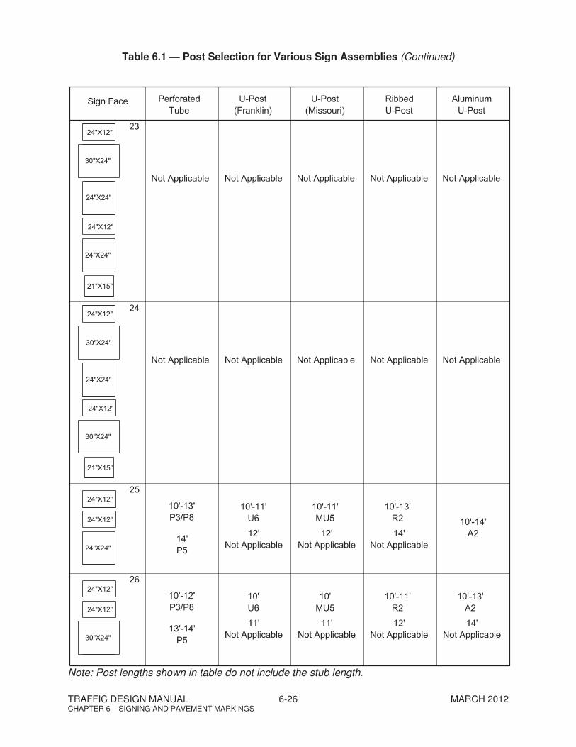
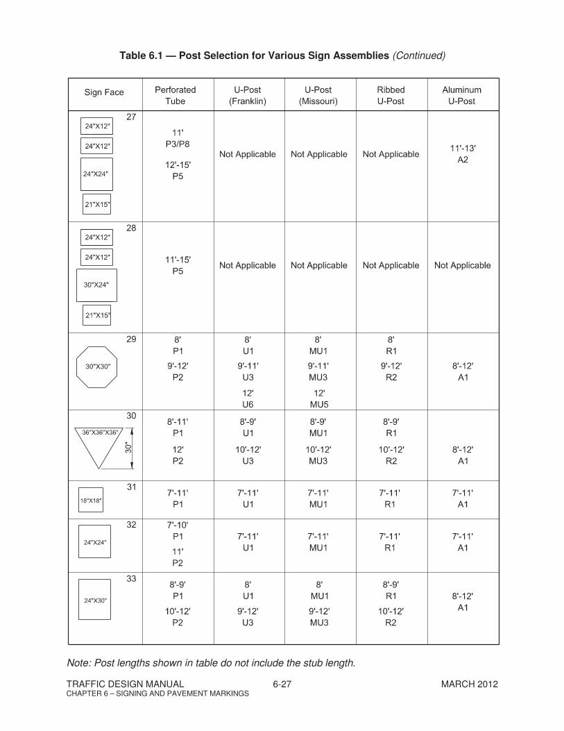
For roadside signs on two-lane, four-lane, and five-lane, non-access controlled, conventional highways, U-posts and P-posts sign supports are most commonly used. Table 6.1 provides guidance on the selection of the appropriate post types based on the support length and sign assembly. For design purposes and quantity calculations, only use P-posts or U-posts, as applicable. When noted on the Sign Schedule Sheet, the Contractor may substitute the post type used in the design with an alternative post type (i.e., MU-post or R-posts).
Figure 6.17 illustrates how to estimate the length of the sign supports for rural and urban roadside signs. Note the support lengths shown in Table 6.1 do not include the stub length in the ground. For P-posts, add 3 feet for the stub. For U-Posts, add 3.5 feet for the stub. For guidance on larger sign supports, including breakaway supports, see Section 6.1.5.3.
Supply and installation of U-posts and P-posts are measured for payment by the pound. Compute the weight of U-posts using the weight per foot of the support multiplied by the combined length of the main post and stub post. Compute the weight of P-Posts using the weight per foot multiplied by the length of the support (excluding the stub) and then add the weight of the stub to the total. Table 6.2 provides the nominal weight per foot for the U-post and P-posts supports used by TDOT.
6.1.4.4 Strain Poles
Certain overhead signs (e.g., street name signs, exclusive lane signs) are commonly attached to a cable wire over the roadway. The cable is then attached to a steel strain pole. Where steel strain poles are included in the design, the designer is responsible for including the strain pole foundation design in the Signing Detail Sheets. Figure 6.18 illustrates a typical foundation design and cable connection details for a strain pole. The strain pole itself is to be designed by the Contractor and is to meet the criteria in the latest version of the AASHTO Standard Specifications for Structural Supports for Highway Signs, Luminaires and Traffic Signals.

TRAFFIC DESIGN MANUAL 6-21 MARCH 2012 CHAPTER 6 – SIGNING AND PAVEMENT MARKINGS
Table 6.1 — Post Selection for Various Sign Assemblies Note: Post lengths shown in table do not include the stub length.

TRAFFIC DESIGN MANUAL 6-22 MARCH 2012 CHAPTER 6 – SIGNING AND PAVEMENT MARKINGS
Table 6.1 — Post Selection for Various Sign Assemblies (Continued) Note: Post lengths shown in table do not include the stub length.

TRAFFIC DESIGN MANUAL 6-23 MARCH 2012 CHAPTER 6 – SIGNING AND PAVEMENT MARKINGS
Table 6.1 — Post Selection for Various Sign Assemblies (Continued) Note: Post lengths shown in table do not include the stub length.

TRAFFIC DESIGN MANUAL 6-24 MARCH 2012 CHAPTER 6 – SIGNING AND PAVEMENT MARKINGS
Table 6.1 — Post Selection for Various Sign Assemblies (Continued) Note: Post lengths shown in table do not include the stub length.

TRAFFIC DESIGN MANUAL 6-25 MARCH 2012 CHAPTER 6 – SIGNING AND PAVEMENT MARKINGS
Table 6.1 — Post Selection for Various Sign Assemblies (Continued) Note: Post lengths shown in table do not include the stub length.
TRAFFIC DESIGN MANUAL 6-26 MARCH 2012 CHAPTER 6 – SIGNING AND PAVEMENT MARKINGS
Table 6.1 — Post Selection for Various Sign Assemblies (Continued)
Note: Post lengths shown in table do not include the stub length.
TRAFFIC DESIGN MANUAL 6-27 MARCH 2012 CHAPTER 6 – SIGNING AND PAVEMENT MARKINGS
Table 6.1 — Post Selection for Various Sign Assemblies (Continued) Note: Post lengths shown in table do not include the stub length.

TRAFFIC DESIGN MANUAL 6-28 MARCH 2012 CHAPTER 6 – SIGNING AND PAVEMENT MARKINGS
Table 6.1 — Post Selection for Various Sign Assemblies (Continued) Note: Post lengths shown in table do not include the stub length.
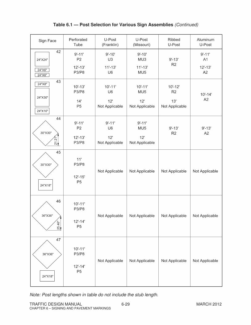
TRAFFIC DESIGN MANUAL 6-29 MARCH 2012 CHAPTER 6 – SIGNING AND PAVEMENT MARKINGS
Table 6.1 — Post Selection for Various Sign Assemblies (Continued) Note: Post lengths shown in table do not include the stub length.

TRAFFIC DESIGN MANUAL 6-30 MARCH 2012 CHAPTER 6 – SIGNING AND PAVEMENT MARKINGS
Table 6.1 — Post Selection for Various Sign Assemblies (Continued) Note: Post lengths shown in table do not include the stub length.

TRAFFIC DESIGN MANUAL 6-31 MARCH 2012 CHAPTER 6 – SIGNING AND PAVEMENT MARKINGS
Table 6.1 — Post Selection for Various Sign Assemblies (Continued) Note: Post lengths shown in table do not include the stub length.

TRAFFIC DESIGN MANUAL 6-32 MARCH 2012 CHAPTER 6 – SIGNING AND PAVEMENT MARKINGS
Figure 6.17 — Estimating Length of Support

TRAFFIC DESIGN MANUAL 6-33 MARCH 2012 CHAPTER 6 – SIGNING AND PAVEMENT MARKINGS
Table 6.2 — Determining Weight of Sign Supports
Perforated Tube (P-Post) U-Post
Member Designation
Unit Post Weight
(LBS/FT)
Stub Below Ground(1)
(LBS)
Member Designation
Unit Post Weight
(LBS/FT)
Stub Below Ground(2)
(LBS/FT)
P1 1.702 1½ 11.09 U1 2.00 2.00
P2 2.060 1¾ 12.96 U2 2.25 2.25
P3 2.416 2 14.84 U3 2.50 2.50
P4 2.773 2¼ 14.84 U4 2.75 2.75
P5 3.141 2½ 23.72 U5 2.75 2.75
P6 4.006 2½ 24.59 U6 3.00 3.00
P7 1.882 1¾ 8.66 U7 4.00 4.00
P8 2.164 2 9.94
(1) To determine the weight of the post, multiply the length of the support (above ground) by
the unit weight in the table and then add the weight of the stub. (2) Add the length of stub (3.5 feet) to the post length as determined from Figure 6.17 and
multiply the total length by the unit weight shown in the table.

TRAFFIC DESIGN MANUAL 6-34 MARCH 2012 CHAPTER 6 – SIGNING AND PAVEMENT MARKINGS
Figure 6.18 — Strain Pole Foundation and Cable Connection Details

TRAFFIC DESIGN MANUAL 6-35 MARCH 2012 CHAPTER 6 – SIGNING AND PAVEMENT MARKINGS
6.1.5 Freeway and Expressway (Access Controlled) Signs
6.1.5.1 Overhead Signing
For overhead signs on access-controlled facilities, the designer is responsible for including the necessary information on the Signing Detail Sheets to allow the Contractor to adequately design the overhead sign bridge or cantilever sign support. The cross-sectional view should include the following:
the overall span length of the overhead structure;
width and height dimensions of the overhead sign, also include the dimension for any auxiliary plaques;
distance from each structural support to the overhead sign, width of the sign, and spacing between signs (if applicable);
the traveled way width and the distance from edge of the traveled way to each structural support;
signs centered vertically on the truss and centered over the appropriate lane of traffic;
the location and distance of the minimum clearance between the roadway surface and the bottom of the tallest overhead sign;
the sign number and station of the sign;
the sign structure ID number (Note: The designer must submit a print of the Detail Sheet to the Structure Division to obtain the ID number.);
in the sign design data, the design area of the sign, the minimum wind velocity, and applicable soil data parameters, see Standard Drawing STD-8-4 for guidance; and
other details notes to the Contractor.
Figure 6.19 illustrates an example of an Overhead Sign Detail Sheet.
The design area of the sign is determined by multiplying the width of the traveled way, auxiliary lanes, and ramp width by the height of the tallest sign. Typically, the sign area for auxiliary plaques is not included in the overall design area of the sign.
The minimum wind velocity for overhead signs is 90 mph. See the AASHTO Standard Specifications for Structural Supports for Highway Signs, Luminaires, and Traffic Signals for guidance.

TRAFFIC DESIGN MANUAL 6-36 MARCH 2012 CHAPTER 6 – SIGNING AND PAVEMENT MARKINGS
Figure 6.19 — Example of Overhead Sign Detail Sheet

TRAFFIC DESIGN MANUAL 6-37 MARCH 2012 CHAPTER 6 – SIGNING AND PAVEMENT MARKINGS
6.1.5.2 Structural Support Foundations
If a sign is mounted on a concrete median barrier (CMB), the designer is responsible for ensuring the applicable Standard Drawings are noted in the contract plans.
6.1.5.3 Roadside Supports
The following supports are commonly used for roadside signs on four-lane, six-lane and eight-lane, access-controlled freeways and expressways:
2, 2½ and 3-inch square posts, S3x5.7 to S7x15.3 steel posts, and W6x15 to W10x30 I-beam steel posts.
Table 6.3 provides guidance on the selection of the appropriate post types for typical sign assemblies assuming a 90-mph wind speed.
Table 6.3 — Support Selection for Access-Control Roadside Signs
(Table 6.3 to be prepared at a later date.)
6.1.6 Sign Vertical Clearances2
Sign vertical clearances are as follows:
1. Rural. The minimum height, measured vertically from the bottom of the sign to the elevation of the near edge of the pavement, of signs installed at the side of the road in rural areas shall be 5 feet (see Figure 6.20). The height to the bottom of a secondary sign mounted below another sign may be 1 foot less.
2. Urban. The minimum height, measured vertically from the bottom of the sign to the top of the curb, or in the absence of curb, measured vertically from the bottom of the sign to the elevation of the near edge of the traveled way, of signs installed at the side of the road in business, commercial, or residential areas where parking or pedestrian movements are likely to occur, or where the view of the sign might be obstructed, shall be 7 feet (see Figure 6-20).
The height to the bottom of a secondary sign mounted below another sign may be 1 foot less than the height specified above.
The minimum height, measured vertically from the bottom of the sign to the sidewalk, of signs installed above sidewalks shall be 7 feet.
If the bottom of a secondary sign that is mounted below another sign is mounted lower than 7 feet above a pedestrian sidewalk or pathway, the
2 2009 MUTCD, FHWA, Section 2A.18 “Mounting Height”
TRAFFIC DESIGN MANUAL 6-38 MARCH 2012 CHAPTER 6 – SIGNING AND PAVEMENT MARKINGS
secondary sign shall not project more than 4 inches into the pedestrian facility.
Signs that are placed 30 feet or more from the edge of the traveled way may be installed with a minimum height of 5 feet, measured vertically from the bottom of the sign to the elevation of the near edge of the pavement.
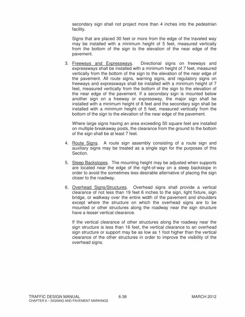
3. Freeways and Expressways. Directional signs on freeways and expressways shall be installed with a minimum height of 7 feet, measured vertically from the bottom of the sign to the elevation of the near edge of the pavement. All route signs, warning signs, and regulatory signs on freeways and expressways shall be installed with a minimum height of 7 feet, measured vertically from the bottom of the sign to the elevation of the near edge of the pavement. If a secondary sign is mounted below another sign on a freeway or expressway, the major sign shall be installed with a minimum height of 8 feet and the secondary sign shall be installed with a minimum height of 5 feet, measured vertically from the bottom of the sign to the elevation of the near edge of the pavement.
Where large signs having an area exceeding 50 square feet are installed on multiple breakaway posts, the clearance from the ground to the bottom of the sign shall be at least 7 feet.
4. Route Signs. A route sign assembly consisting of a route sign and auxiliary signs may be treated as a single sign for the purposes of this Section.
5. Steep Backslopes. The mounting height may be adjusted when supports are located near the edge of the right-of-way on a steep backslope in order to avoid the sometimes less desirable alternative of placing the sign closer to the roadway.
6. Overhead Signs/Structures. Overhead signs shall provide a vertical clearance of not less than 19 feet 6 inches to the sign, light fixture, sign bridge, or walkway over the entire width of the pavement and shoulders except where the structure on which the overhead signs are to be mounted or other structures along the roadway near the sign structure have a lesser vertical clearance.
If the vertical clearance of other structures along the roadway near the sign structure is less than 16 feet, the vertical clearance to an overhead sign structure or support may be as low as 1 foot higher than the vertical clearance of the other structures in order to improve the visibility of the overhead signs.

TRAFFIC DESIGN MANUAL 6-39 MARCH 2012 CHAPTER 6 – SIGNING AND PAVEMENT MARKINGS
Figure 6.20 — Sign Vertical Clearances

TRAFFIC DESIGN MANUAL 6-40 MARCH 2012 CHAPTER 6 – SIGNING AND PAVEMENT MARKINGS
6.1.7 Traffic Signal Signs
The following guidance is provided for traffic control signs at or in advance of signalized intersections. Figure 6.21 illustrates some of the traffic signs associated with traffic signals.
6.1.7.1 Span Wire/Mast Arm Mounted
Where overhead signs are provided, the minimum vertical clearance over the entire roadway is 19 feet 6 inches.
6.1.7.1.1 LEFT TURN SIGNAL Signs (R10-10, R10-12)
1. LEFT TURN SIGNAL Sign (R10-10). This sign is normally installed with a protected only left turn phase. The R10-10 sign is required when a Red Ball indication is used (R, Y, G). Install the sign directly adjacent to and left of the signal head. Additionally, install this sign to the left of each left turn signal (R,
Y, G) in a dual left turn situation.
2. LEFT TURN YIELD ON GREEN BALL Signs (R10-12). This optional sign may be installed with a protected–permissive left turn phase adjacent to and to the left of the five-section left turn signal head (R, Y, G, Y, G).
6.1.7.1.2 Shared Lanes
Where two or more movements from a specific lane and where a one of the movement is not normally expected, install an Optional Movement Lane Control Sign (R3-6).
6.1.7.1.3 Lane Control Signs (R3-5 and R3-8)
Lane use control signs should be used to alert drivers of unexpected or unusual turn requirements for a lane. Where needed, mount these signs overhead in the center of the lane to which they apply. The use of an overhead sign for one lane does not require the installation of signs for the other lanes.
The R3-5 and R3-8 series signs are intended for overhead use. Install these signs directly over a lane for which they apply in order to convey the proper message to a driver. They should not be used for side of road installations. See the 2009 MUTCD for guidance on post mounted lane use control signs.

TRAFFIC DESIGN MANUAL 6-41 MARCH 2012 CHAPTER 6 – SIGNING AND PAVEMENT MARKINGS
Figure 6.21 — Typical Signal Related Signs
6.1.7.1.4 Turn Prohibition Signs (Signs R3-1, R3-2, R3-3, R3-4)
In general, where turns are prohibited, install the appropriate turn prohibitions signs (R3-1 through R3-4), unless one-way signs are used.
1. The NO RIGHT TURN sign (R3-1) may be installed adjacent to the signal face for the right lane.
2. The NO LEFT TURN (R3-2) or NO U-TURN (R3-4) signs may be installed adjacent to a signal face viewed by road users in the left lane.

TRAFFIC DESIGN MANUAL 6-42 MARCH 2012 CHAPTER 6 – SIGNING AND PAVEMENT MARKINGS
3. A NO TURNS (R3-3) sign may be placed adjacent to a signal face for all lanes on that approach or two signs should be used.
4. Where ONE WAY signs are used, turn prohibition signs may be omitted.
6.1.7.1.5 LEFT or RIGHT ON GREEN ARROW ONLY Sign (R10-5)
Where needed, install the R10-5 sign adjacent to the applicable turn signal head. The R10-5 sign is used where it is unsafe to turn left or right except when protected by the green arrow display. Use this sign if a sign is installed for an all arrow turn signal.
6.1.7.1.6 NO TURN ON RED (R10-11a)
Where needed, install the R10-11a sign near the appropriate signal head. A No Turn on Red sign should be considered when an engineering study finds that one or more of the following conditions exists:
Where there is inadequate sight distance to vehicles approaching from the left (or right, if applicable).
Where there are geometrics or operational characteristics of the intersection that might result in unexpected conflicts.
Where there is an exclusive pedestrian phase.
Where there are an unacceptable number of pedestrian conflicts with right-turn-on-red maneuvers, especially involving children, older pedestrians, or persons with disabilities.
Where there are more than three right-turn-on-red crashes reported in a 12-month period for the particular approach.
Where the skew angle of the intersecting roadways creates difficulty for drivers to see traffic approaching from their left.
At railroad crossings where the design vehicle cannot be safely stored in the clear storage distance between the railroad crossing and the adjacent traffic signal (i.e., to prevent trapping a vehicle). See Section 4.8.2 for further guidance.
For multi-lane applications the use of R10-11c or R10-11d may be used to restrict the right-turns-on-red from a specific lane.
6.1.7.1.7 Blank Out Signs
Blank Out Signs are internally illuminated signs that are blanked out (show no message) when not illuminated. They are often used when a turn prohibition is in effect only at certain times of the day or during one or more portion(s) of a particular cycle of the traffic signal.
Another application of blank out signs is where a signal has a railroad preemption sequence and left and right turns towards the tracks are prohibited once an approaching train is detected. In this turn prohibition

TRAFFIC DESIGN MANUAL 6-43 MARCH 2012 CHAPTER 6 – SIGNING AND PAVEMENT MARKINGS
application, the blank sign would be located to the right of the right most signal if the right turn is prohibited, and to the left of the left turn signal if the left turn is prohibited.
6.1.7.1.8 Street Name Signs (D3-1)
Street name signs are installed by the local jurisdiction. If mounted overhead, the lettering should be composed of initial upper-case letters at least 12 inches in height and lower-case letters at least 9 inches in height. Ensure the support poles are designed to accommodate loadings for street name signs if they will be installed during or after the project.
6.1.7.2 Ground Mounted Signs
The following discuss ground-mounted signs to be used at or in advance of signalized intersections.
6.1.7.2.1 Turn Lane Supplemental Signs (R3-7)
Ground mounted mandatory lane control signs should be used to alert drivers of unexpected or unusual turn requirements for a lane or if turning movement traffic frequently fills the turn lane to capacity. The R3-7 signs, LEFT (RIGHT) LANE MUST TURN LEFT (RIGHT) can be installed to alert the driver, but is not required for all turn lanes.
Simply having a dedicated right turn lane does not automatically require the installation of RIGHT LANE MUST TURN RIGHT signs. However, if a through lane ends as a right turn only lane, then install the appropriate R3-5 overhead sign and/or R3-7 ground mounted sign.
6.1.7.2.2 SIGNAL AHEAD Sign (W3-3)
The installation of this sign is appropriate under the following conditions:
1. Signal Visibility. Where visibility of the traffic signal heads on any approach is less than the distances shown in MUTCD Table 4D-2, install an advance Signal Ahead sign (W3-3) to warn approaching traffic of the signal.
2. Speed. On high-speed rural approaches, approaching the first signal in an urbanized area, the W3-3 sign may be justified.
3. Engineering Judgment. In other situations where engineering judgment reveals the need for the W3-3 sign (e.g., for additional emphasis even where the visibility distance to the device is sufficient).
A warning beacon may be used to provide additional emphasis to a Signal Ahead sign (see Section 5.2.6).
6.1.7.2.3 Street Name Signs (D3-1)
Street name signs are installed only by the local jurisdiction. The minimum lettering heights are 6 inches for initial upper-case letters and

TRAFFIC DESIGN MANUAL 6-44 MARCH 2012 CHAPTER 6 – SIGNING AND PAVEMENT MARKINGS
4.5 inches for lower-case letters. For multi-lane facilities where the speed limit is greater than 40 mph, the minimum lettering heights are 8 inches for initial upper-case letters and 6 inches for lower-case letters.
6.1.8 Other Traffic Control Signs
6.1.8.1 SPEED LIMIT Signs (R-2 series)
SPEED LIMIT signs shall be posted at the points where the speed limits change. Ensure that both directions are consistent. Additional signs should be installed beyond major intersections to inform traffic of the posted speed limit.
6.1.8.2 Two-Way Left-Turn Lane Signs (R3-9 series)
Two-Way Left-Turn Lane signs are installed to inform drivers of the required use of a center turn lane. They are installed as a supplement to the standard pavement markings and should be located as often as the speed limit signs.
6.1.8.3 School Signs
School signs shall have a fluorescent yellow-green background with a black legend and border.

TRAFFIC DESIGN MANUAL 6-45 MARCH 2012 CHAPTER 6 – SIGNING AND PAVEMENT MARKINGS
6.2 PAVEMENT MARKINGS
All pavement markings shall meet the design and installation requirements of the MUTCD. Pavement markings are constantly degrading and must be replaced at regular intervals to be effective.
6.2.1 Stop Lines3
6.2.1.1 Guidance
Stop lines should be used to indicate the point behind which vehicles are required to stop to be in compliance with a stop sign, traffic signal, or other traffic control devices. Stop lines have the following characteristics:
Line Type – solid Line Width – 24 inches Color – white Orientation – generally parallel to cross street curb line (see Figures 6.22
and 6.23)
6.2.1.2 Placement
When determining the placement of the stop line, consider the following:
1. Sight Distance. Position the stop line to allow the motorist adequate sight distance of the cross street traffic.
2. Staggered. Stop lines may be staggered longitudinally on a lane-by-lane basis; see Figure 6.22. Check turning paths of the design vehicles from the cross street to ensure there are no conflicts. For must intersections, use the turning path of a single-unit (SU) design vehicle to determine the location of the stop line.
3. Crosswalks. Where used, place the stop line a minimum of 4 feet in advance of the nearest crosswalk line at controlled intersections, except at midblock crosswalks (see Figure 6.23).
4. No Crosswalk. In the absence of a marked crosswalk, place the stop line at the desired stopping point, but not more than 30 feet or less than 4 feet from the nearest edge of the intersecting traveled way (see Figure 6.23).
5. Mid-block Crossings. Stop lines at midblock signalized locations should be placed at least 40 feet in advance of the nearest signal indication.
6. Uncontrolled Multi-lane Approaches. If stop lines are used at a crosswalk that crosses an uncontrolled multi-lane approach, the stop lines should be placed 20 feet to 50 feet in advance of the nearest crosswalk line, and parking prohibited in the area between the stop line and the crosswalk.
3 2009 MUTCD, FHWA, Section 3B.16 “Stop and Yield Lines”

TRAFFIC DESIGN MANUAL 6-46 MARCH 2012 CHAPTER 6 – SIGNING AND PAVEMENT MARKINGS
Figure 6.22 — Stop Line Placement

TRAFFIC DESIGN MANUAL 6-47 MARCH 2012 CHAPTER 6 – SIGNING AND PAVEMENT MARKINGS
Figure 6.23 — Stop Line Locations

TRAFFIC DESIGN MANUAL 6-48 MARCH 2012 CHAPTER 6 – SIGNING AND PAVEMENT MARKINGS
6.2.2 Yield Lines4
6.2.2.1 Guidance
Yield lines may be used to indicate the point behind which vehicles are required to yield in compliance with a YIELD (R1-2) sign or a Yield Here To Pedestrians (R1-5 or R1-5a) sign. Yield lines have the following characteristics:
Symbol – solid triangle Base Width – 12 inches to 24 inches Height – 1.5 times the base width Color – white Orientation – generally parallel to cross street curb line Spacing Between Triangles – 3 inches to 12 inches
6.2.2.2 Placement
When determining the placement of the yield line, consider the following:
1. Sight Distance. Position the yield line to allow the motorist adequate sight distance of the cross street traffic.
2. Staggered. Yield lines may be staggered longitudinally on a lane-by-lane basis. Check turning paths of the design vehicles from the cross street to ensure there are no conflicts. For most intersections, use the turning path of a single-unit (SU) design vehicle to determine the location of the yield line.
3. Crosswalks. Where used, place the yield line a minimum of 4 feet in advance of the nearest crosswalk line at controlled intersections or roundabouts, except at midblock crosswalks.
4. No Crosswalk. In the absence of a marked crosswalk, place the yield line at the desired yield point, but not more than 30 feet or less than 4 feet from the nearest edge of the intersecting traveled way.
5. Uncontrolled Multi-lane Approaches. If yield lines are used at a crosswalk that crosses an uncontrolled multi-lane approach, the yield line should be placed 20 feet to 50 feet in advance of the nearest crosswalk line, and parking prohibited in the area between the yield line and the crosswalk. If yield lines are used at a crosswalk that crosses an uncontrolled multi-lane approach, Yield Here To (Stop Here For) Pedestrians (R1-5 series) signs shall be used.
6. Roundabouts. A yield line may be used to indicate the point behind which vehicles are required to yield at the entrance to a roundabout.
4 Ibid. 3B.16
TRAFFIC DESIGN MANUAL 6-49 MARCH 2012 CHAPTER 6 – SIGNING AND PAVEMENT MARKINGS
6.2.3 Crosswalks5
6.2.3.1 Guidance
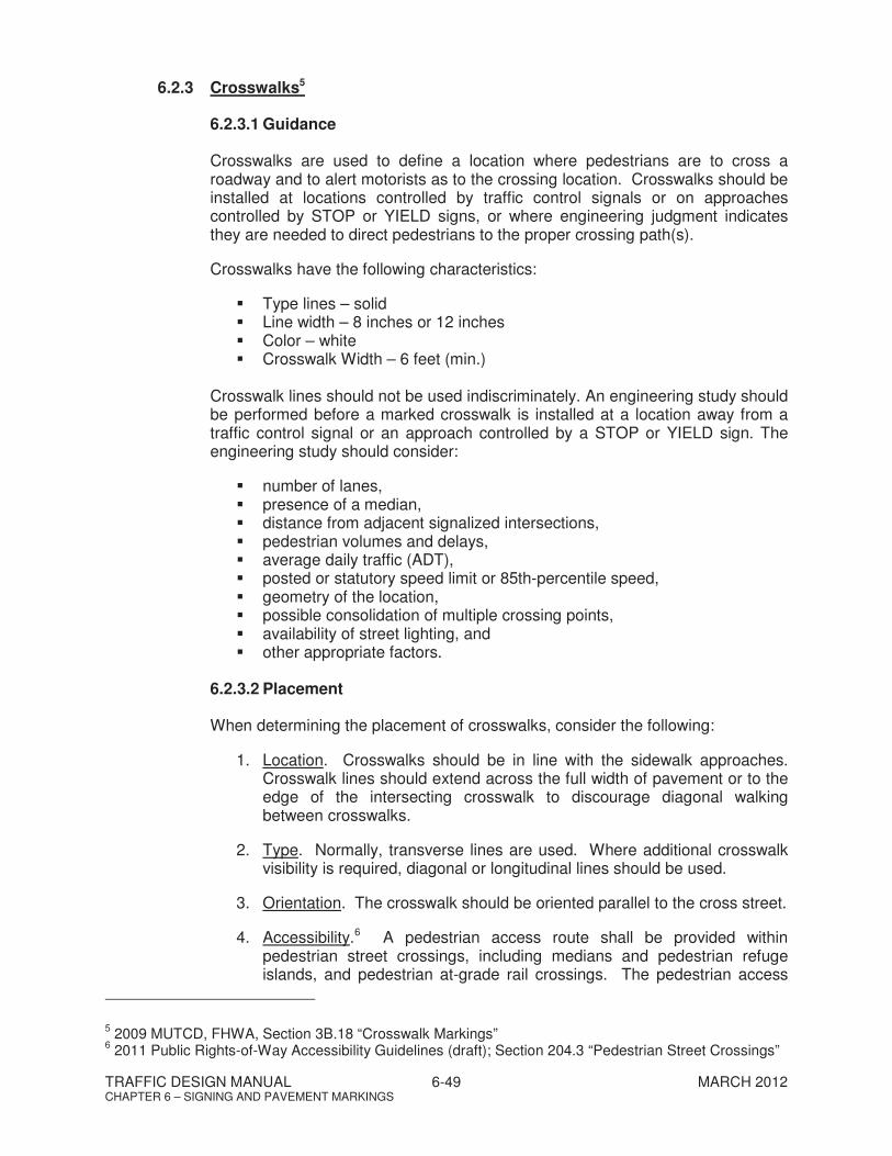
Crosswalks are used to define a location where pedestrians are to cross a roadway and to alert motorists as to the crossing location. Crosswalks should be installed at locations controlled by traffic control signals or on approaches controlled by STOP or YIELD signs, or where engineering judgment indicates they are needed to direct pedestrians to the proper crossing path(s).
Crosswalks have the following characteristics:
Type lines – solid Line width – 8 inches or 12 inches Color – white Crosswalk Width – 6 feet (min.)
Crosswalk lines should not be used indiscriminately. An engineering study should be performed before a marked crosswalk is installed at a location away from a traffic control signal or an approach controlled by a STOP or YIELD sign. The engineering study should consider:
number of lanes, presence of a median, distance from adjacent signalized intersections, pedestrian volumes and delays, average daily traffic (ADT), posted or statutory speed limit or 85th-percentile speed, geometry of the location, possible consolidation of multiple crossing points, availability of street lighting, and other appropriate factors.
6.2.3.2 Placement
When determining the placement of crosswalks, consider the following:
1. Location. Crosswalks should be in line with the sidewalk approaches. Crosswalk lines should extend across the full width of pavement or to the edge of the intersecting crosswalk to discourage diagonal walking between crosswalks.
2. Type. Normally, transverse lines are used. Where additional crosswalk visibility is required, diagonal or longitudinal lines should be used.
3. Orientation. The crosswalk should be oriented parallel to the cross street.
4. Accessibility.6 A pedestrian access route shall be provided within pedestrian street crossings, including medians and pedestrian refuge islands, and pedestrian at-grade rail crossings. The pedestrian access
5 2009 MUTCD, FHWA, Section 3B.18 “Crosswalk Markings” 6 2011 Public Rights-of-Way Accessibility Guidelines (draft); Section 204.3 “Pedestrian Street Crossings”

TRAFFIC DESIGN MANUAL 6-50 MARCH 2012 CHAPTER 6 – SIGNING AND PAVEMENT MARKINGS
route shall connect departure and arrival sidewalks. All pedestrian street crossings must be accessible to pedestrians with disabilities. If pedestrian crossing is prohibited at certain locations, No Pedestrian Crossing signs (R9-3) should be provided along with detectable features (e.g., grass strips, landscaping, planters, chains, fencing, railings).
5. Curb Ramps. The curb ramp, excluding any flared sides, or blended transition shall be contained wholly within the width of the pedestrian street crossing served.
6. Roundabouts. Pedestrian crosswalks shall not be marked to or from the central island of roundabouts. If pedestrian facilities are provided, crosswalks should be marked across roundabout entrances and exits to indicate where pedestrians are intended to cross. Crosswalks should be a minimum of 20 feet from the edge of the circulatory roadway.
6.2.4 Arrows
Pavement marking arrows should be used for specific turn lanes. The turn arrow marking will suffice, the word “ONLY” is optional. Where a through lane approaching an intersection becomes a mandatory turn lane the word “ONLY” used with the turn arrow is required.
6.2.5 Materials
All stop lines, crosswalks, and arrows shall be constructed of reflectorized thermoplastic or pre-formed plastic pavement marking material. The material used shall be in accordance with the TDOT Standard Specifications.