Embed Size (px)
Citation preview

Chapter 6
Smoke Test for Cabin Materials
6.1 Scope
6.1.1 This test method is used to determine the smoke generating characteristics of airplane
passenger cabin interior materials to demonstrate compliance with the requirements of FAR
25.853.
6.2 Definitions
6.2.1 Specific Optical Density (Ds)-Specific Optical Density
Specific optical density (Ds)-specific optical density is a dimensionless measure of the amount
of smoke produced per unit area by a material when it is burned. In this test, the maximum
value of Ds that occurs during the first 4 minutes of a test, 4Dm, is reported.
6.3 Test Apparatus
6.3.1 Required Equipment
The test chamber and related equipment (e.g., radiant heat furnace, heat flux density gauge,
specimen holders, photometric system, multidirectional pilot burner, etc.) are defined as
follows.
6.3.1.1 Test Chamber
The test chamber will be a square-cornered box with inside dimensions of 36 ± 0.13
inches (914 ± 3 mm) wide, 24 ± 0.13 inches (610 ± 3 mm) deep, and 36 ± 0.13
inches (914 ± 3 mm) high. A typical test chamber is shown in figure 6-1. The
location or size of items such as the chamber door, chamber controls, flowmeters,
etc., is optional except as mandated in the following sections.
6.3.1.1.1 The interior surfaces (except for the chamber door, vents, etc.) will be
porcelain-enameled metal or equivalent coated metal that is resistant to
chemical attack and corrosion and suitable for periodic cleaning. The
chamber will be equipped with a door such as that indicated in figure 6-
1 to provide convenient access for changing test specimens and for
cleaning the chamber walls as required. The door will have a viewing
window to observe the sample and pilot flamelets behavior during a
test, especially when any of the flamelets extinguish (see section
6.7.2.10).
Figure 6-1. Typical Smoke Density Chamber

6.3.1.1.2 An inlet-outlet vent for pressure equalization will be provided. The
vent and chamber door will have a seal so that when it is closed during
tests, there will be no leakage of chamber contents and a small positive
pressure can be developed and maintained inside the test chamber.
6.3.1.2 Manometer
A device such as a manometer or pressure transducer will be provided to monitor
chamber pressure and leakage. The device will have a range up to 6 inches (152
mm) of water and be connected to a suitable port in the test chamber.
6.3.1.3 Pressure Regulator
A pressure regulator will be provided that consists of a water-filled bottle vented to
a suitable exhaust system and a piece of tubing, not to exceed 10 feet (305 cm) in
length, that has an inside diameter of at least 1 inch (25 mm). One end of the
tubing will be connected to a port within 6 inches of the top of the chamber; the
other end of the tubing will be held in position 4 inches (102 mm) below the water
surface.
6.3.1.4 Test Chamber Wall Thermocouple
The temperature of the test chamber wall will be monitored by a thermocouple
suitable for measuring a temperature of 35°C. The thermocouple will be mounted
with its junction secured to the geometric center of the inner rear wall panel of the
chamber using an electrically insulating disk cover.
6.3.1.5 Electric Power
A single-phase electric power of 650 W will be provided for the radiant heat
furnace and accessories. Where line voltage fluctuations exceed 2.5 percent, a
constant voltage transformer will be provided.
6.3.1.6 Radiant Heat Furnace
An electric furnace and associated controlling devices (see figures 6-2 and 6-3) will
be provided that are capable of providing a constant thermal flux density of 2.5 ±
0.05 W/cm2 (2.2 ± 0.04 Btu/ft
2/second) on the specimen surface.
6.3.1.6.1 Furnace Construction
The dimensions shown in figure 6-2 for the electric furnace are critical.
The furnace will be located centrally along the long axis of the
chamber, with the opening facing toward and approximately 12 inches
(305 mm) from the right wall. The centerline of the furnace will be
approximately 7.75 inches (197 mm) above the chamber floor.
6.3.1.6.2 Heating Element
The heating element will consist of a coiled wire capable of dissipating
about 525 W. With the furnace installed, the heating element will be
positioned so that the coil loops are at the 12 o’clock position, as shown
in figure 6-3.
6.3.1.6.3 Furnace Control System
The furnace control system will be capable of controlling the radiant
heat output at the required level of 2.5 ± 0.05 W/cm2 (2.2 ± 0.04
Btu/ft2/second), as measured by the heat flux density gauge, under
steady-state conditions with the chamber door closed for at least 5
minutes. The control system will consist of an AC solid-state voltage
or power controller and a voltmeter or other means for monitoring the
electrical input.

Figure 6-2. Furnace Section
Figure 6-3. Heater Orientation
6.3.1.6.4 Heat Flux Density Gauge
An air-cooled heat flux density gauge will be provided for calibrating
the output of the radiant heat furnace. The heat flux density gauge will
be a circular foil type, the operation of which was described by Gardon.
6.3.1.6.4.1 Compressed air at a pressure of 15 to 30 psi (0.1 to 0.21
MPa) will be provided to cool the heat flux density gauge.
The body temperature of the heat flux density gauge will
be monitored with a thermometer having an accuracy of
2°F (1°C) at 200°F (93°C) in a 0.5- by 0.5- by 1.5-inch
(13- by 13- by 38-mm) -long brass or copper well drilled
to accept the thermometer with a close fit. Silicone
grease will be used to provide good thermal contact. The
circular receiving surface of the heat flux density gauge
will be spray-coated with an infrared-absorbing black
paint. The heat flux density gauge will be calibrated

calorimetrically using a procedure that is acceptable to the
FAA Administrator.
6.3.1.7 Pilot Burner
The pilot burner will be a multiple flamelet type with six tubes, as shown in figure
6-4. The six tubes will be fabricated from stainless steel tubing having an outer
diameter of 0.125 inch (3.2 mm) and an inner diameter of 0.055 inch (1.4 mm) ±
0.001 inch (0.025 mm). The six tubes will be attached to a common manifold, as
shown in figure 6-4, fabricated from stainless steel tubing having an outer diameter
of 0.25 inch (6.4 mm) and a wall thickness of 0.035 inch (0.9 mm). One end of the
manifold will be closed and the other end will be attached to a gas supply fitting on
the chamber floor.
Figure 6-4. Alignment of Holder and Burner
6.3.1.7.1 The two outer tubes of the pilot burner will be directed perpendicular to
the surface of the specimen. The two inner tubes will be directed at an
angle of 45 degrees downward. The two intermediate tubes will be
directed vertically downward into the drip pan of the specimen holder.
6.3.1.7.2 The pilot burner will be centered in front of and parallel to the
specimen holder. The tips of the two outer tubes will be placed 0.25 ±

0.06 inch (6.4 ± 1.5 mm) above the lower opening of the specimen
holder and 0.25 ± 0.06 inch (6.4 ± 1.5 mm) away from the face of the
specimen surface.
6.3.1.8 Pilot Burner Fuel
The gas fuel for the pilot burner will be prepared by mixing filtered oil-free air with
95 percent minimum purity propane. This mixture will then be fed to the pilot
burner. Each gas will be metered through separate, calibrated flowmeters and
needle valves. The air-propane mixture will consist of an air flow rate equivalent
to 0.018 ± 0.001 ft3/min (500 ± 20 cm
3/min) at standard temperature and pressure
(STP) and a propane flow rate equivalent to 0.0018 ± 0.0001 ft3/min (50 ± 3
cm3/min) at STP. The compressed air supply will be fed to its flowmeter at 20 ± 5
psi (0.14 ± 0.03 MPa) and the propane at 15 ± 3 psi (0.1 ± 0.02 MPa).
6.3.1.8.1 The visible parts of the pilot burner flamelets should be approximately
0.25 inch (6 mm) long with a luminous inner cone approximately 0.13
inch (3 mm) long, as shown in figure 6-5. If the flamelets are not that
approximate size, there is probably a difficulty with the air/propane fuel
mixture and/or flow rate(s), in which case the accuracy of the
flowmeters should be checked.
Figure 6-5. Flame Size
6.3.1.9 Specimen Holder
The specimen holder will consist of a stainless steel frame, a backing made of
insulation millboard, a spring and retaining rod to secure the specimen in place,
and aluminum foil for wrapping the specimen.
6.3.1.9.1 Specimen Holder Frame
The specimen holder frame will be fabricated of stainless steel sheet by
bending and brazing (or spot welding) stainless steel sheet of 0.025 ±
0.002 inch (0.64 ± 0.05 mm) nominal thickness to conform in shape
and dimension to figure 6-6. The frame will be at least 1.5 inches (38
mm) deep and will provide an exposed specimen surface that is

nominally 2.56 by 2.56 inches (65 by 65 mm) and that is at least 6.5
inches2 (4,194 mm
2) in area.
6.3.1.9.1.1 A drip pan to catch and retain dripping material will be
attached to the bottom front of the holder.
6.3.1.9.1.2 Guides to permit accurate alignment of the exposed
specimen area in front of the furnace opening will be
attached to the top and bottom of the holder frame.
Figure 6-6. Details of Specimen Holder
6.3.1.9.1.3 Two wires made of 0.02 ± 0.005-inch (0.5 ± 0.12-mm)
diameter stainless steel, vertically oriented and evenly
spaced (0.85 inch from the edge of the holder’s vertical
face openings and 0.85 inch from each other), will be
attached to the holder face.
6.3.1.9.2 Specimen Backing
A piece of insulation millboard will be used as a backing for the
specimen and as a simulated blank specimen. The millboard will be
nominally 0.5 inch (13 mm) thick with a density of 50 ± 10 lb/ft3 (0.8 ±
0.16 g/cm3), or equivalent. Pieces will be cut 2.91 ± 0.03 inches by
2.91 ± 0.03 inches (74 ± 1 mm by 74 ± 1 mm) to fit inside the specimen
holder.
6.3.1.9.3 Retaining Spring
A spring bent from a 3- (76-mm) by 2.94- (75-mm) by 0.01-inch (0.25-
mm) -thick stainless steel sheet will be used with a stainless steel
retaining rod to securely hold the specimen and millboard backing in
position during testing.
Thickness
0.025 ±±±± 0.002 in
(0.64 ±±±± 0.05 mm)

6.3.1.9.4 Aluminum Foil
Smooth aluminum foil that is 0.0012 ± 0.0005 inch (0.03 ± 0.01 mm)
thick will be used to wrap test specimens prior to their insertion in the
holder.
6.3.1.10 Support for Radiant Heat Furnace and Specimen Holder
A typical support frame to support the radiant heat furnace and specimen holder is
shown in figure 6-7. This support frame will have a provision to establish accurate
alignment for the furnace opening so that it is 1.5 ± 0.031 inches (38 ± 1 mm) away
from, parallel to, and centered with the exposed specimen surface. Adjustment
screws will be provided to align the furnace with reference to the specimen.
Figure 6-7. Typical Furnace Support
The framework will have two 0.38-inch (10-mm) -diameter transverse rods of
stainless steel to accept the guides of the specimen holder. The rods will support
the holder so that the exposed specimen surface is parallel to the furnace opening.
Spacing stops will be mounted at both ends of each rod to permit rapid and accurate
lateral positioning of the specimen holder. An externally operated control rod will
be provided to replace the test specimen with the blank specimen holder in front of
the furnace.
6.3.1.11 Photometric System
A photometric system capable of detecting light transmittance values of 1 percent
minimum to an accuracy of 0.03 percent will be provided. The system will consist
of a light source and photomultiplier tube that are oriented vertically to reduce
measurement variations due to stratification of the smoke in the chamber during the
test, a photomultiplier microphotometer that converts the photomultiplier tube
output either to relative intensity and/or to optical density, and a strip chart recorder
or other suitable means to record light transmission versus time. A typical system
is shown in figures 6-8 and 6-9.
6.3.1.11.1 Light Source
The light source will be an incandescent lamp mounted in a sealed,
lighttight box below the chamber floor, operated at a light brightness

temperature of 2200 ± 100K controlled by a constant-voltage
transformer. The box will contain the necessary optics to produce a
collimated light beam 1.5 ± 0.13 inches (38 ± 3 mm) in diameter,
passing vertically up through the chamber. The light source and its
optics will be isolated from the chamber atmosphere by a glass window
that is mounted flush with the chamber bottom panel and sealed to
prevent leakage of chamber contents. To minimize smoke
condensation, the window will be provided with a ring-type electric
heater mounted in the lighttight box, out of the light path, that
maintains a minimum window temperature of 125°F (52°C) on the
surface of the window inside the chamber.

Figure 6-8. Photometer Detail

Figure 6-9. Photometer Location
6.3.1.11.2 Photomultiplier Tube
The photomultiplier tube will have an S-4 linear spectral response and a
dark current less than 10-9
ampere.
6.3.1.11.2.1 The photomultiplier tube and associated optics will be
mounted in a second lighttight box that is located above
the chamber ceiling directly opposite the light source.
The photomultiplier tube and its optics will be isolated
from the chamber atmosphere by a glass window that is
mounted flush with the chamber ceiling panel. The
window, which permits viewing a cross section of 1.5 ±
0.13 inches (38 ± 3 mm), will be sealed to prevent
leakage of chamber contents.
6.3.1.11.3 Microphotometer
The microphotometer will be capable of converting the signal from the
photomultiplier tube to relative intensity and/or to optical density. The
microphotometer/photomultiplier tube combination will be sensitive
enough that the microphotometer can be adjusted to produce a full-
scale reading (100 percent relative light intensity or optical density = 1)
using the photomultiplier tube’s response (output) to the light source
when a filter of 0.5 or greater optical density is placed in the light path.
6.3.1.11.4 Alignment Fixture
The two optical windows and their housings will be kept in alignment
and spaced 36 ± 0.125 inches (914 ± 3 mm) apart with an alignment
fixture consisting of three metal rods 0.5 - 0.75 inch (13 - 19 mm) in
diameter fastened securely to 0.31-inch (8-mm) -thick externally
mounted top and bottom plates and symmetrically arranged about the
collimated light beam.
6.3.1.11.5 Optical Filters
A set of nine neutral color optical filters of 0.1, 0.2, 0.3, 0.4, 0.5, 0.6,
0.7, 0.8, and 0.9 optical density will also be provided. The optical
filters, one or more as required, may be mounted in the light path in the
optical measuring system to compensate for the sensitivity of the

photomultiplier tube. These filters may also be used to adjust the
photometric system as the light source and/or photomultiplier tube
change sensitivity through aging and/or as discoloration or
deterioration of the optical windows occurs.
6.3.1.11.6 Recorder
A recording device will be furnished that provides a record of the
percent light transmission and/or optical density versus time during the
test. The record will consist either of a continuous curve on a chart
recorder or discrete values taken at least every 5 seconds with a
computerized data acquisition system.
6.3.1.12 Exhaust Hood
A method for removing the chamber contents after each test will be provided. A
fitting for removing the chamber contents may be connected to a suitable exhaust
hood. Locating an exhaust hood directly above the smoke chamber door is
recommended as an additional safety device.
6.3.1.13 Conditioning Chamber
A conditioning chamber capable of maintaining test specimens at a temperature of
70° ± 5°F (21° ± 3°C) and 50% ± 5% relative humidity will be provided.
6.4 Test Specimen Selection and Preparation
6.4.1 Specimen Number
A minimum of three specimens will be prepared and tested for each part/construction.
6.4.2 Specimen Selection
Specimens will either be taken from an actual part or built to simulate a part.
6.4.2.1 Flat sections of the same thickness and composition may be tested in place of curved,
molded, or specialty parts.
6.4.2.2 Both faces of a multilayer assembly will be tested as a separate part/construction if
the outer materials are different on the faces and if both sides are exposed to the
passenger cabin interior. If both faces must be tested, two sets of specimens will be
provided.
6.4.3 Specimen Size
Each specimen will be 2.9 ± 0.06 by 2.9 ± 0.06 inches (73 ± 2 by 73 ± 2 mm). The specimens
will be the same thickness as the thickness of the part/construction.
6.4.4 Specimen Orientation
For materials that may have anisotropic flammability properties (i.e., different properties in
different directions, such as machine and cross-machine directions for extrusions, warp and fill
directions of a woven fabric, etc.), specimens will be tested in the orientation thought to give
the highest result. If the average 4Dm is greater than 180, a second set of specimens will be
prepared and tested in the orientation that is perpendicular to the orientation used for the first
set of specimens. The higher of the two average 4Dm values will be reported.
6.4.5 Specimen Preparation
All surfaces of the specimen, except the surface to be exposed for the test, will be wrapped
with aluminum foil (see section 6.3.1.9.4) prior to placing them in a specimen holder. The side
of the foil with dull finish will be placed next to the specimen. After the specimen is placed in
a specimen holder, any aluminum foil on the exposed specimen will be removed from the
bottom (to avoid interference with the pilot burner flamelets) and either removed or folded

back on the other three sides (to avoid covering any of the exposed specimen surface area).
The specimen will be placed in a holder, followed by an alumina-silica backing board, the
spring plate, and the retaining rod (see figure 6-6).
6.5 Specimen Conditioning
6.5.1 Specimens will be conditioned at a temperature of 70° ± 5°F (21° ± 3°C) and 50% ± 5%
relative humidity for a minimum of 24 hours unless otherwise specified. Only one specimen at
a time will be removed from the conditioning chamber. When removed, the specimen will be
immediately tested.
6.6 Test Chamber Calibration
6.6.1 Furnace Protection
Prepare a blank specimen consisting of 0.5-inch-thick alumina-silica millboard (see section
6.3.1.9.2) mounted in a specimen holder. To reduce problems with the stability of the heat
flux density from the furnace, maintain the blank specimen in front of the furnace when no
testing or calibration is being conducted.
6.6.2 Periodic Calibration Procedure
Conduct a periodic calibration of the system as follows.
6.6.2.1 Photometric System
The photometric system used in this test method is an inherently linear device.
Check the system for proper photocell alignment. Verify, at least every 2 months,
the linearity of the system using a set of neutral optical density filters or equivalent.
If erratic behavior is observed or suspected, check the system more frequently.
6.6.2.2 Furnace
Use the approved heat flux density gauge to monitor the heat flux density produced
by the furnace. Place the heat flux density gauge on the horizontal rods of the
furnace support framework and accurately position it in front of the furnace
opening by sliding and displacing the blank specimen holder against the spacing
stop (see section 6.3.1.10). With the chamber door closed and the inlet vent
opened, adjust the compressed air supply to the heat flux density gauge cooler to
maintain its body temperature at 200° ± 50°F (93° ± 3°C). Adjust the setting of the
furnace control voltage or power controller to obtain the calibrated millivolt output
of the heat flux density gauge corresponding to a steady-state irradiance of 2.5 ±
0.05 W/cm2 (2.2 ± 0.04 Btu/ft
2/second). After the irradiance has reached the
required value and has remained steady-state for at least 5 minutes, remove the heat
flux density gauge from the chamber and replace it with the blank specimen holder.
6.6.2.2.1 Record the setting of the furnace control voltage or power controller
and use this setting until a future calibration indicates it should be
changed.
6.6.2.3 Chamber Leak Test
Test the smoke density chamber leak rate at least once a month, or more often if
loss of chamber pressure is suspected, using the following procedure.
6.6.2.3.1 Close the inlet vent and the chamber door.
6.6.2.3.2 Pressurize (e.g., by bleeding in a small amount of air through the port
used for the heat flux density gauge) the chamber to at least 3 inches of
water above ambient as indicated by the manometer.
6.6.2.3.3 Note the chamber pressure. Verify that the chamber pressure leakage
rate is less than 2 inches of water in 2 minutes.

6.6.2.4 Total System
Check the total system at least once a month by testing a material that has shown a
consistent specimen-to-specimen 4Dm value in the range of 150 to 220
4Dm and that
is, and will continue to be, readily available. Maintain a record of the test results
obtained. If erratic values are observed, identify and correct any instrumental or
operational deficiencies.
6.6.3 Chamber Cleaning
Clean the optical system windows, viewing window, chamber walls, and specimen holders as
follows.
6.6.3.1 Optical System Windows
Clean the exposed surfaces of the glass separating the photo detector and light
source housings from the interior of the chamber after each test. Clean the top
window first, then the bottom window, using a nonabrasive cloth dampened with a
suitable cleaner. Dry the window to prevent streaking or film buildup. Do not use
any cleaners that contain wax because wax will cause the smoke to adsorb to the
glass more quickly.
6.6.3.2 Viewing Window
Clean the viewing window periodically as required to allow viewing the chamber
interior during testing. The same cleaners used in section 6.6.3.1 have been found
satisfactory.
6.6.3.3 Chamber Walls
Clean the chamber walls periodically to prevent excessive build-up of smoke
products. An ammoniated spray detergent and nonabrasive scouring pad have been
found effective.
6.6.3.4 Specimen Holders
Remove any charred residue on the specimen holders and horizontal rods securing
the holder position to prevent contamination of subsequent specimens.
6.7 Test Procedure
6.7.1 Each day, prior to testing, adjust the chamber as follows.
6.7.1.1 Calibrate the furnace output according to section 6.6.2.2 to determine the correct
furnace voltage.
6.7.1.2 Balance the photomultiplier dark current and set the clear beam reading to 100
percent relative transmission or to optical density 0.00.
6.7.1.3 Set the photomultiplier scale at 100. Shut the lower shutter blade (D) directly
below photomultiplier tube (B) (see figure 6-8). Set zero on the data recording
device.
6.7.2 Conduct the test procedure as follows.
6.7.2.1 Ensure that the specimen(s) have been properly prepared per sections 6.4.1 through
6.4.5.
6.7.2.2 Ensure that the chamber wall temperature is 95° ± 4°F (35° ± 2°C).
6.7.2.3 Ensure that the furnace voltage has been set correctly.
6.7.2.4 Set the clear beam reading to 100 percent relative transmission or to optical density
0.00. See section 6.7.1.2.

6.7.2.5 Position the pilot burner in front of and parallel to the specimen holder. Turn on
the pilot burner fuel (see section 6.3.1.8) and light the flamelets on the pilot burner.
Make sure all flamelets are ignited and properly adjusted.
6.7.2.6 Remove a test specimen from the conditioning chamber, open the test chamber
door, and place the specimen holder on the support. Immediately push the
specimen holder into position in front of the furnace, displacing the blank specimen
holder to the prepositioned stop, and close the chamber door and inlet vent. For
chambers with an external device to move the specimen holder in front of the
furnace, place the holder on the support, close the door, slide the sample into
position, and simultaneously start the timer and recorder for light transmission.
6.7.2.7 Continue the test for a minimum of 4 minutes (240 seconds). Do not perform any
analysis of the chamber contents, such as gas sampling, during the first 4 minutes
(240 seconds) of testing.
6.7.2.8 Record the percent light transmission and/or optical density versus time (minutes)
during the test.
6.7.2.9 Monitor the chamber pressure during the test. If negative pressure (below ambient
atmospheric) develops, open the inlet valve slightly to relieve negative pressure.
6.7.2.10 Monitor the pilot burner flamelets during the test. Note and record if either of the
outer flamelets oriented perpendicular to the specimen surface or if either of the
inner flamelets oriented 45 degrees to the specimen surface extinguishes and
remains continuously extinguished for more than 3 seconds. If such extinguishing
occurs, the test results from that specimen are not valid, and the test may be
terminated and another test started with a new test specimen.
6.7.2.11 At the termination of the test, remove the test specimen holder from its position in
front of the furnace and replace it with the blank specimen holder using the exterior
control rod. Begin exhausting the chamber of smoke within 1 minute by opening
the door and the inlet vent (and exhaust vent, if used).
6.7.2.11.1 Continue to exhaust the chamber until all smoke has been removed.
6.7.2.12 Clean the windows to the housings for the photomultiplier tube and the light source
per section 6.6.3.1.
6.7.2.13 Calculate and record the maximum specific optical density, 4Dm, during the 4-
minute (240-second) test for each specimen according to the formula:
( ) ( )( )m
mm
T
TLAVD4
10
410
4
/100log132
/100log/
=
=
where:
V = chamber volume = 18.00 ft3 (0.510 m
3)
L = light path length = 3.00 ft (0.914 m)
A = exposed specimen area = 6.57 in2 (0.00424 m
2)
4T = minimum percent light transmission during 4 minutes
log10(100/4Tm) = maximum optical density during 4 minutes
6.7.2.14 Calculate and record the average 4Dm value and its standard deviation for all the
specimens tested for each part/construction. Use the actual 4Dm values for this
average; do not use the average light transmission value to determine the average 4Dm value.

6.8 Report
6.8.1 Report a complete identification of the part/construction tested, such as material construction,
thickness, weight, etc.
6.8.2 Report the number of specimens tested and the average 4Dm.
6.8.3 Report any additional data or observations as applicable and/or required by the test plan.
6.9 Requirements
6.9.1 Through FAR 25.853(c-1) Amendment 25-72, the average 4Dm during the 4-minute test will
not exceed 200.

Chapter 6 Supplement
This supplement contains advisory material pertinent to referenced paragraphs.
6.2.1 In most cases, the maximum specific optical density (4Dm) should be at 4 minutes; however, due to
coagulation of smoke particles, or to adsorption of smoke particles to the walls of the chamber, it is
possible for the maximum to occur earlier in the test.
6.3.1 Recommended Equipment
The following items are recommended but not required:
• Digital Voltmeter—Preferred to monitor furnace voltage and heat flux density gauge output. A
Keithley Model 165 Autoranging Multimeter or equivalent has been found acceptable.
• Constant Voltage Transformer—A constant voltage transformer is recommended for all
installations (see section 6.3.1.5).
• Pilot Burner Positioning Fixture—A fixture to accurately position the pilot burner is
recommended to establish a precise pilot burner position for testing and to facilitate accurate
repositioning of pilot burner after removal and replacement (see figure 6-10).
Figure 6-10. Burner Position (Optional)
A more precise positioning device is available from Newport Scientific. Its part number is 680860354000.
• Reignition System—A reignition system is recommended to relight the horizontal and 45-degree
pilot burner flamelets to ensure that none of them extinguishes for more than 3 seconds during the
test. The preferred method of reignition is a manually operated sliding tube, with a propane and
air mix, adjusted to impinge on the pilot outlets as it is moved across an area adjacent to the pilot
flames. A method of operating this could be made similar to the device in the smoke chamber that
moves the sample, i.e., push-pull rod (see figure 6-4). If an electric sparking device is used, an
appropriate method of suppression and equipment shielding must be applied to have no
interference with the ability of the data acquisition equipment to accurately record data.

6.3.1.1 Commercially available panels of porcelain-enameled steel (interior surface) permanently
laminated to a magnesia insulation core and backed with galvanized steel (exterior surface) have been
found acceptable.
A thin sheet of transparent material may be placed over optical and viewing windows to protect them from
corrosive components in the smoke.
6.3.1.3 Venting the water-filled pressure regulator to a suitable exhaust system is necessary to prevent
the buildup of unknown contaminates in the laboratory area. The location of the pressure relief tube should
be on or within 6 inches of the top of the chamber.
6.3.1.5 A powerstat variable autotransformer, Type 21, from Superior Electric Co., Bristol,
Connecticut, or equivalent has been found satisfactory to transform electric power to that required by the
chamber.
A constant voltage transformer from Sola Electric Co., Chicago, Illinois, Catalog Number 23-13-150, or
equivalent, has been found satisfactory. A Sorenson Model 200S AC voltage regulator, or equivalent, has
been found satisfactory.
6.3.1.6 Furnace model P/N 6806025700 from Newport Scientific has been found acceptable.
Furnace model P/N 680860380000 from Newport Scientific has also been found acceptable. A calibration
device, P/N 4-5808, is also available from Newport Scientific.
6.3.1.6.3 A model 470 Series power controller manufactured by Eurotherm and a Model 3AEV1B10C1
Triac manufactured by General Electric Company, or equivalent, have been found satisfactory.
The furnace control system should be a reputable unit that provides the parameters to fulfill the
requirements of the furnace.
It is recommended to use a digital voltmeter to monitor the furnace voltage output and a digital
amperemeter to monitor the furnace current.
6.3.1.6.4 Gardon, R., “An Instrument for the Direct Measurement of Intense Thermal Radiation,”
Review of Scientific Instruments, Vol. 24, 1953, pp. 360-370.
A thermocouple system capable of measuring 200° ± 2°F is an acceptable alternate method to monitor the
body temperature of the heat flux density gauge.
6.3.1.7 The pilot burner should be aligned with a sample holder and backing board in place. A
description of a suitable method of alignment is shown in figure 6-4. Care should be taken to ensure
accurate positioning of the pilot tips to the sample holder.
6.3.1.8 Commercially bottled propane has been found acceptable.
6.3.1.9.1 Mounting the wire through holes made in the drip pan attachment mount between the top of the
drip pan and the bottom of the holder across the face of the specimen and over the top of the holder, and
through holes made in the flange of the top guide just above the top of the holder has been found
satisfactory. This scheme permits the use of only one piece of wire threaded through the four holes with
the two ends twisted together behind the guide at the top of the holder.
Sample holders must be checked for accuracy with each other; for example, top and bottom mounting
devices consistent with each other. It has been noted that misalignment between holders does result in pilot
position errors.
6.3.1.9.2 A recommended material is Marinite I.
6.3.1.9.4 Aluminum foil used for household food wrapping is acceptable.
6.3.1.11.2 A thin sheet of transparent material may be placed over optical and viewing windows to
protect them from corrosive components in the smoke.
6.4.1 Conditions may require as many as six specimens. For test purposes, specimens should be marked
with an arrow for a consistent direction by manufacturers or operators.
6.6.3.1 Ethyl alcohol, methyl ethyl ketone, or equivalent has been found satisfactory.
6.7.1.2 This procedure is described in AMINCO NBS Smoke Density Chamber, Catalog No. 4-5800B,
Instruction 941B.
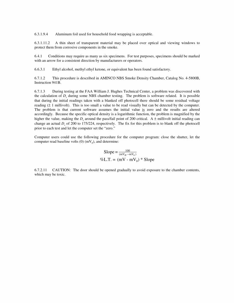
6.7.1.3 During testing at the FAA William J. Hughes Technical Center, a problem was discovered with
the calculation of Ds during some NBS chamber testing. The problem is software related. It is possible
that during the initial readings taken with a blanked off photocell there should be some residual voltage
reading (± 1 millivolt). This is too small a value to be read visually but can be detected by the computer.
The problem is that current software assumes the initial value is zero and the results are altered
accordingly. Because the specific optical density is a logarithmic function, the problem is magnified by the
higher the value, making the Ds around the pass/fail point of 200 critical. A ± millivolt initial reading can
change an actual Ds of 200 to 175/224, respectively. The fix for this problem is to blank off the photocell
prior to each test and let the computer set the “zero.”
Computer users could use the following procedure for the computer program: close the shutter, let the
computer read baseline volts (0) (mVb), and determine:
)mV(mV
100 = SlopebH −
%L.T. = (mV - mVb) * Slope
6.7.2.11 CAUTION: The door should be opened gradually to avoid exposure to the chamber contents,
which may be toxic.