Embed Size (px)
Citation preview

RPS V1 - March 2006 Part 11 - Planning Scheme Policy 9 - Infrastructure Works - Chapter 6 - Page 95
Chapter 6 - Stormwater Management 9.6.1 Purpose (1) The purpose of this chapter of the policy is to -
(a) set out the requirements for the preparation and submission of plans and technical reports for the design of stormwater management systems associated with development applications under the planning scheme;
(b) ensure stormwater run-off does not adversely impact the quality of receiving waters, including waterways, wetlands, Moreton Bay and the marine environment;
(c) provide an efficient and effective stormwater management system that provides adequate protection for people and property from the effects of overland flow or flooding;
(d) maintain the natural flow regime of the site; (e) identify the requirements for the implementation of Water Sensitive Urban Design (WSUD)
Principles. 9.6.2 Applicability This chapter of the policy applies to all development sites under the planning scheme which are subject to stormwater run-off. 9.6.3 Legislative Framework 9.6.3.1 Context (1) The local government’s approved specifications for stormwater construction works conform to
AUS-SPEC # 1- Construction, except as amended in this policy. (2) The Stormwater Management Code and this chapter of the policy aim to ensure that development
within the local government area is consistent with Ecologically Sustainable Development (ESD) and the requirements of -
(a) Integrated Planning Act 1997;
(b) Environmental Protection Act 1994;
(c) Environmental Protection (Water) Policy 1997;
(d) the local government Corporate Plan;
(e) South East Queensland Regional Water Quality Management Strategy (SEQWRMS);
(f) Redland Shire Council Urban Stormwater Management Plan 2002.
(3) The local government Urban Stormwater Management Plan (USMP) establishes the framework
for the management of stormwater in a way consistent with ESD. This is achieved through the promotion of Water Sensitive Urban Design Principles.
(4) Water Sensitive Urban Design Principles essential to the USMP -
(a) minimise the contamination of waters by stormwater;
(b) maximise the infiltration of water into the ground;
(c) reduce the velocity of stormwater;
(d) remove contaminants from the stormwater.

Page 96 - Part 11 - Planning Scheme Policy 9 - Infrastructure Works - Chapter 6 RPS V1 - March 2006
(5) Measures to achieve these principles include -
(a) flow rate mitigation;
(b) erosion control;
(c) infiltration areas;
(d) grassed or vegetated drainage lines;
(e) vegetated waterway buffers;
(f) conservation or restoration of riparian vegetation;
(g) artificial wetlands;
(h) gross pollutant traps;
(i) retention basins;
(j) trash racks. (6) Planning and design approaches for stormwater systems have regard to the needs of the local
community. Approaches include -
(a) minimising ecological impacts on local waterways;
(b) acceptable health risks;
(c) aesthetics;
(d) protection from flooding;
(e) public safety and other social concerns;
(f) making use of stormwater for recycling and water conservation;
(g) making use of drainage corridors for improved recreational values and open space or landscape areas.
(7) Investigating opportunities to build contaminant control measures and re-establish riparian
vegetation and aesthetically pleasing environments in drainage corridors. (8) Integrating stormwater management planning with catchment-based planning and land use
planning. (9) Implementing viable alternatives to the release of stormwater through outlets across beaches or
into waters with poor circulation. (10) Ensure the design of the stormwater system maintains an acceptable level of maintenance. (11) The Stormwater Management Code and policy provides a mechanism to implement commitments
made in the local government Urban Stormwater Management Plan (USMP). The provisions contained within the code and policy reflects best practice methods of achieving these goals.
(12) Applicable guidelines include -
(a) Urban Stormwater Best Practice Environmental Management Guidelines - CSIRO 1999;
(b) Stormwater Quality Control Guidelines for Local Government - Department of Natural Resources Mines and Energy and Department of Environment 1998;
RPS V1 - March 2006 Part 11 - Planning Scheme Policy 9 - Infrastructure Works - Chapter 6 - Page 97
(c) The Constructed Wetland Manual Volume 1 and 2 - Department of Land and Water Conservation NSW 1998;
(d) Natural Channel Design Guidelines - Brisbane City Council December 2000;
(e) Stormwater Outlets in Parks and Waterways - Brisbane City Council Version 2/2003;
(f) Australian Run-off Quality.
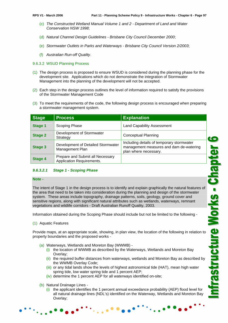
9.6.3.2 WSUD Planning Process (1) The design process is proposed to ensure WSUD is considered during the planning phase for the
development site. Applications which do not demonstrate the integration of Stormwater Management into the planning of the development will not be accepted.
(2) Each step in the design process outlines the level of information required to satisfy the provisions
of the Stormwater Management Code (3) To meet the requirements of the code, the following design process is encouraged when preparing
a stormwater management system. Stage Process Explanation Stage 1 Scoping Phase Land Capability Assessment
Stage 2 Development of Stormwater Strategy Conceptual Planning
Stage 3 Development of Detailed Stormwater Management Plan
Including details of temporary stormwater management measures and dam de-watering plan where necessary.
Stage 4 Prepare and Submit all Necessary Application Requirements.
9.6.3.2.1 Stage 1 - Scoping Phase Note - The intent of Stage 1 in the design process is to identify and explain graphically the natural features of the area that need to be taken into consideration during the planning and design of the stormwater system. These areas include topography, drainage patterns, soils, geology, ground cover and sensitive regions, along with significant natural attributes such as wetlands, waterways, remnant vegetations and wildlife corridors - Draft Australian Runoff Quality, 2003. Information obtained during the Scoping Phase should include but not be limited to the following - (1) Aquatic Features Provide maps, at an appropriate scale, showing, in plan view, the location of the following in relation to property boundaries and the proposed works -
(a) Waterways, Wetlands and Moreton Bay (WWMB) - (i) the location of WWMB as described by the Waterways, Wetlands and Moreton Bay
Overlay; (ii) the required buffer distances from waterways, wetlands and Moreton Bay as described by
the WWMB Overlay Code; (iii) or any tidal lands show the levels of highest astronomical tide (HAT), mean high water
spring tide, low water spring tide and 1 percent AEP; (iv) determine the 1 percent AEP for all waterways identified on-site;
(b) Natural Drainage Lines -
(i) the applicant identifies the 1 percent annual exceedance probability (AEP) flood level for all natural drainage lines (NDL’s) identified on the Waterway, Wetlands and Moreton Bay Overlay;

Page 98 - Part 11 - Planning Scheme Policy 9 - Infrastructure Works - Chapter 6 RPS V1 - March 2006
(ii) the natural drainage flowpath areas identified as below the 1 percent AEP flood event level are preserved or enhanced in a natural state where the - a. development has an upstream catchment area of 5 hectares or more; or b. premises has an area of 2500m2 or greater;
(iii) drainage flowpaths which intersect at an existing road sag and have an upstream area greater than 5 hectares, are retained for the full natural width of the 1 percent AEP flood level on the downstream side of the road in order to preserve the natural drainage lines;
(iv) roads may be constructed along natural drainage lines if the upstream catchment is less than 5 hectares in order to cater for the 1 percent AEP flood level event;
(v) the minimum width preserved for a natural drainage line is 15 metres; Note - The Waterways, Wetlands and Moreton Bay Overlay may not show all NDL’s within the development site. It is the applicant’s responsibility to identify all NDL’s on-site.
(c) other aquatic features within or adjacent to the site including intermittent water features, dams, man made channels and other relevant features;
(2) Drainage Patterns and Soil Types -
(a) provide information relating to the topography of the site - the topography of the area will assist in determining the range of applicable stormwater treatment measures which can be incorporated into the planning of the development site;
(b) identify the soil types present and provide comments on their erodability and their potential for
infiltration. (3) Environmental Values and Water Quality objectives -
(a) identify the relevant environmental values and associated water quality objectives as per Schedule 11.
(4) Vegetation -
(a) identify graphically all on-site vegetation;
(b) identify the location of enhancement corridors and enhancement habitat as specified in the Habitat Protection Overlay.
(5) Open Space -
(a) identify the location of proposed open space. 9.6.3.2.2 Stage 2 - Development of a Stormwater Strategy (1) Stage 2 in the design process involves the conceptual design of the stormwater management
system using Water Sensitive Urban Design principles. Refer to section 9.6.3.1 - (3). (2) The Stormwater Management Code and policy promotes the use of a treatment train approach
when designing the stormwater system. A treatment train approach refers to the implementation of stormwater quality improvement measures in a series to maximise their performance. The treatment train consists of the following -
Source ⇓
Conveyance ⇓
Discharge :
Natural Systems Planning

RPS V1 - March 2006 Part 11 - Planning Scheme Policy 9 - Infrastructure Works - Chapter 6 - Page 99
(3) This approach minimises stormwater pollution by in-transit measures and maximises the performance of individual components through correct placement in the treatment train. As depicted in Diagram 1, no single treatment measure is capable of treating the full spectrum of pollutants. Therefore it is essential to ensure that a number of treatments are used to meet water quality objectives.
Diagram 1
(4) The selection and implementation of structural treatment measures involves six steps -
(a) determine treatment objectives - (i) identify the relevant environmental values and associated water quality objectives for the
area as per Schedule 11; (ii) establish the pollutants of concern in the catchment such as litter, sediments and
nutrients; (iii) establish the level of treatment required to meet the water quality objectives;
(b) develop a treatment train -
(i) assess the treatment process required to maximise the efficiency of each component of the stormwater treatment train;
(ii) for example, remove coarse sediments and control flow prior to removal of nutrients; Note - When designing the treatment train, aspects of road design, public open space, landscaping and other criteria are considered.
(c) Site identification - identify potential sites and site constraints using information obtained during Stage 1 - Scoping Phase;
(d) Shortlist potential treatments and identify all applicable treatment measures, for example -
(i) litter traps; (ii) swales; (iii) infiltration trenches; (iv) bio-retention systems; (v) wetlands; (vi) stormwater re-use; (vii) road designs landscape design;
(e) Compare potential treatments - compare all potential treatments for removal efficiency,
maintenance requirements, social impacts and costs;

Page 100 - Part 11 - Planning Scheme Policy 9 - Infrastructure Works - Chapter 6 RPS V1 - March 2006
Note - Refer Diagram 2 for example of stormwater treatment train. Diagram 2 - Sketch Depicting Stormwater Treatment Train
5 Hectares
OpenSpace
NaturalDrainage
Line
Future DevelopmentArea
5 Hectares
AreaFuture Development
Minor Waterway
Legend
Point of stormwater discharge from development
Swale drainStormwater catchment boundaries of approx 5 hectare
Kerb and channel
Future road extentionConstructed wetland
Approximately
Approximately
Waterway Buffer
9.6.3.2.3 Stage 3 - Detailed Stormwater Management Plan (1) Applicants undertake adequate hydraulic and hydrologic studies showing the measures
undertaken to provide non-worsening of current stormwater discharge. This ensures that the quality, velocity and quantity of stormwater discharge post-development is not increased over the predevelopment state at the downstream discharge point.
(2) Refer Infrastructure Works Policy - Chapter 4 - Erosion Prevention and Sediment Control, for
further details.

RPS V1 - March 2006 Part 11 - Planning Scheme Policy 9 - Infrastructure Works - Chapter 6 - Page 101
Note - A maintenance lifecycle cost analysis is supplied with designs of stormwater treatment systems. Stormwater design is in accordance with the following standards. 9.6.4 Standards 9.6.4.1 Stormwater Management Systems Stormwater management systems are designed in accordance with the requirements of the Queensland Urban Drainage Manual (QUDM), and Australian Rainfall and Runoff (ARR), except when it is otherwise specified in this chapter of the policy. Note - References in this chapter of the policy are to clause or table numbers in the QUDM unless stated otherwise. 9.6.4.2 Design Criteria (1) Preliminary calculations for overland stormwater flow on roads and natural flow-paths are included
when the application is submitted for the development layout inspection, in order to verify that the overland flow paths are adequate at all locations throughout the development. The initial preliminary calculations do not need to be precise.
(2) Design calculations similar to the format given in QUDM and in accordance with requirements of
QUDM or ARR, as appropriate, are submitted with the development application for examination by the local government.
(3) Electronic data files that have been used to analyse the stormwater flows are supplied in
electronic and hard copy format. 9.6.4.3 Calculation of Runoff (1) Methods of stormwater run-off calculation or modeling are selected by considering the suitability of
use of the particular method in accordance with QUDM and ARR requirements. (2) The rational method is not acceptable for catchments which contain significant storage areas.
Methods as described in QUDM and ARR are used for such catchments. 9.6.4.4 Intensities (1) Rainfall intensities are calculated in accordance with procedures of ARR. (2) The local government’s Table 1 in this chapter may be used as a guide to determine rainfall
intensities used in stormwater runoff calculations for storm durations. 9.6.4.5 Coefficient of Runoff The local government’s Table 2 in this chapter is recommended for use for the determination of coefficients of run-off. Refer QUDM Table 5.04.1 for fraction impervious values vs. development categories. 9.6.4.6 Time of Concentration (1) QUDM Table 5.05.1 may be used for the calculation of inlet time for Urban Residential Zone and
Medium Density Residential Zone lots but not for Low Density Residential Zone. (2) A calculation in accordance with recommendations in QUDM and/or ARR is adopted for Park
Residential Zone lots and larger upstream lots.

Page 102 - Part 11 - Planning Scheme Policy 9 - Infrastructure Works - Chapter 6 RPS V1 - March 2006
9.6.4.7 Design Frequency (1) The major system design is 1 percent AEP (100 years ARI). (2) The minor system design is in accordance with the local government planning scheme Stormwater
Management Code, Table 1. Table 1 is generally in accordance with QUDM Table 5.06.1. (3) In addition to Table 1 of the Stormwater Management Code, the following design frequencies
apply -
(a) Pedestrian bridges over waterways, pedestrian paths and recreation equipment in active and passive recreation areas are above the 50 percent AEP. The underside of the bridge deck support is above the design water surface level;
(b) Floor levels of amenities buildings, which are not connected to the sewerage reticulation
system in parks or recreation areas, are above the 10 percent AEP. Those connected to the sewerage reticulation system are above the 1 percent AEP;
(c) Open area sporting areas and playing fields are above the 100 percent AEP;
(d) Urban residential Level III inter-lot drainage is designed for a 50 percent AEP flood level.
(4) The drainage in a catchment that is receiving discharge from an area of a higher AEP is designed
to cater for the greater design discharge from upstream. The AEP in the downstream catchment may be reduced to its normal recurrence interval at a convenient location such as a park area where the higher design flow can surcharge safely.
(5) The drainage in a catchment that is receiving discharge from an area of a lower AEP is designed
to cater for a discharge from that upstream area at the same frequency as the downstream catchment. Sufficient inlet capacity is provided to cater for the additional design bypass flow from the upstream catchment where it meets a catchment of higher design recurrence interval.
(6) Design frequencies for drainage of the Department of Main Roads and Queensland Railways
Infrastructure are in accordance with the current policies of the Department of Main Roads and Queensland Rail.

RPS V1 - March 2006 Part 11 - Planning Scheme Policy 9 - Infrastructure Works - Chapter 6 - Page 103
Table 1 Intensity Frequency Duration
Rainfall Intensity in mm/hr Duration ANNUAL EXCEEDENCE PROBABILITY (Minutes) 100% 50% 20% 10% 5% 3.3% 2% 1%
5 6 7 8 9
121 114 107 102 97
154 144 136 130 124
190 178 168 160 153
210 197 186 177 169
238 224 212 201 192
254 239 226 215 206
275 258 244 232 222
302 284 269 256 245
10 11 12 13 14
93 89 86 83 80
118 114 110 106 102
146 141 136 131 127
162 156 150 145 141
184 177 171 165 160
197 190 183 177 171
213 205 198 191 185
235 226 218 211 204
15 16 17 18 19
78 76 74 72 70
99 96 94 91 89
123 119 116 113 110
136 133 129 126 122
155 151 147 143 139
166 161 157 153 149
180 174 170 165 161
198 192 187 182 178
20 21 22 23 24
68 66 65 64 62
87 85 83 81 79
108 105 103 100 98
119 117 114 112 109
136 133 130 127 124
145 142 139 136 133
157 154 150 147 144
174 170 166 163 159
25 26 27 28 29
61 60 59 57 56
78 76 75 73 72
96 95 93 91 89
107 105 103 101 99
122 120 117 115 113
131 128 126 123 121
141 139 136 134 131
156 153 150 148 145
30 31 32 33 34
55 54 54 53 52
71 69 68 67 66
88 86 85 84 82
98 96 95 93 92
111 110 108 106 104
119 117 115 114 112
129 127 125 123 121
143 140 138 136 134
35 36 37 38 39
51 50
49.6 48.8 48.2
65 64 63 62 61
81 80 79 78 77
90 89 88 86 85
103 101 100 99 97
110 109 107 106 104
119 118 116 114 113
132 130 128 126 125
40 41 42 43 44
47.5 46.9 46.3 45.7 45.1
61 60 59 58 57
76 75 74 73 72
84 83 82 81 80
96 95 93 92 91
103 101 100 99 98
111 110 108 107 106
123 121 120 118 117
45 46 47 48 49
44.5 44.0 43.5 43.0 42.5
57 56 55 55 54
71 70 69 68 68
79 78 77 76 75
90 89 88 87 86
97 95 94 93 92
105 103 102 101 100
116 114 113 112 111
50 51 52 53 54
42.0 41.5 41.1 40.6 40.2
54 53 52 52 51
67 66 65 65 64
75 74 73 72 72
85 84 83 82 82
91 90 89 88 87
99 98 97 96 95
109 108 107 106 105
55 56 57 58 59 60
39.8 39.4 39.0 38.6 38.2 37.9
51 50
49.8 49.3 48.8 48.3
63 63 62 62 61 60
1 70 69 69 68 67
1 80 79 78 78 77
87 86 85 84 83 83
94 93 92 91 90 89
104 103 102 101 100 99

Page 104 - Part 11 - Planning Scheme Policy 9 - Infrastructure Works - Chapter 6 RPS V1 - March 2006
Table 2
Fractions Impervious and Coefficients
Description Fraction
Impervious (includes roads) f
100% AEP C
50% AEP C
10% AEP C
1% AEP C
Medium Density Residential Zone (including sub-area MDR 1) Urban Residential Zone Fee Simple Lots. 300m2 400m2 500m2 (Urban Res.) 550m2 600m2 700m2 800m2 900m2 Low Density Res. 2000m2 Park Residential 6000m2 Parks & Open Space Canal Estates Central Business Commercial Industrial Roads and car parking areas
0.80 0.80 0.70 0.60 0.55 0.50 0.45 0.40 0.35 0.30 0.20 0.00 0.75 1.00 0.90 0.90 0.90
0.53
0.72 0.70 0.68 0.67 0.66 0.65 0.65 0.64 0.62 0.60 0.56 0.75 0.75
0.85 0.85 0.82 0.80 0.79 0.78 0.77 0.76 0.75 0.73 0.71 066 0.84 0.90 0.88 0.88 0.88
1.00 1.00 0.98 0.96 0.95 0.94 0.92 0.91 0.90 0.88 0.85 0.79 1.00 1.00 1.00 1.00 1.00

RPS V1 - March 2006 Part 11 - Planning Scheme Policy 9 - Infrastructure Works - Chapter 6 - Page 105
9.6.5 Roof and Inter-lot Drainage 9.6.5.1 General (1) Developers are to provide either Level I or II roof water drainage or Level III roof and surface inter-
lot drainage to Urban Residential Zone developments. For multiple dwelling developments, community management statement, commercial and industrial developments, developers are to provide Level III or Level IV or Level V drainage. Applicability of such provisions is in accordance with the requirements of the Queensland Urban Drainage Manual (QUDM), except as specified herein.
(2) A rear of lot roof or inter-lot drainage system is provided to all lots where -
(a) The lot generally falls away from the frontage kerb and channel, such that a roof water drainage pipe cannot be connected to the frontage kerb and channel or the street drainage system;
(b) The finished surface level of the lot is less than 600mm at the middle of the lot above the
lowest invert level along the frontage kerb and channel where no accessible street drainage system exists;
(c) New Urban Residential Zone lots are being created downstream of existing lots which have no
drainage system. Surface water from existing lots and roof water down pipes from the existing dwellings are connected to the new drainage system at the developer’s expense. If the developer were not able to obtain permission to enter the existing lots to carry out such work, the local government would assist the developer in obtaining such approvals;
(d) Urban Residential Zone developments in which proposed lots would naturally discharge run-
off onto existing or possible future lower lots, or in which higher land would naturally concentrate runoff onto proposed lots.
(3) Private easements in favour of the upstream property owners are provided over Level III and V
inter-lot drainage pipes. The easement width is to encompass the drainage infrastructure and will generally be a minimum width of 1.5 metres.
(4) Easements are not required over Level II roof water drainage lines where only two lots are
connected. (5) A minimum Level I standard of roof drainage is required in Park Residential Zones. (6) Where roof drains connect to kerb and channel, the pipe across the verge may be uPVC class
SN4 or equivalent placed on compacted sand bedding or, where applicable, galvanised steel rectangular hollow section of 100mm maximum height.
(7) Where more than one such RHS is required, each is placed not less than 25mm apart and welded
together, using a steel spacer between the sections. The whole item is galvanised after fabrication.
(8) The pipe or RHS is connected to the kerb and channel via a kerb adaptor (KA), the end of which is
to match the profile of the kerb and channel at the point where the kerb adaptor passes through the kerb.
(9) The kerb adaptor may be cast in at the time the kerb is constructed. (10) The opening may be saw cut and reinstated with mortar after the kerb adaptor is installed - refer to
standard drawing number R-RSC-7. 9.6.5.2 Urban Residential Roof Drainage (1) As a minimum, provision is made for a Level I or Level II roof drainage connection for all Urban
Residential Zone lots in new reconfigurations.

Page 106 - Part 11 - Planning Scheme Policy 9 - Infrastructure Works - Chapter 6 RPS V1 - March 2006
(2) A roof drainage system is provided for Urban Residential Zone lots, which are subject to run-off from higher lots. The standard is QUDM Level II. Roof drainage Level II may be used where no more than one line of higher lots contributes runoff to the lower lots before a street intervenes.
(3) Notwithstanding the detail in QUDM Figure 5.18.1(b), roof drainage is provided via a 150mm
diameter pipe through a downhill lot with only one upper lot and the lower lot connected to the pipe and discharging to the lower street.
(4) Roofwater connection points provided to each upper lot are located 4 metre upstream from the
lower side property boundary and 1 metre past the alignment of the sewer line. (5) Notwithstanding the requirements of QUDM, the trunk drainage system is designed essentially
without consideration of the Level I and Level II roof drainage system where only two lots are connected, except for the location of stormwater inlets and access chambers. Catchment boundaries remain unchanged.
(6) There will be no penalty in terms of increased head loss or flow on the street drainage system
where the Level I or Level II, maximum 2 lots roof drainage system connects. (7) One connection point is provided on the roof water drainage line for each property. This
connection is in the form of an inspection opening Y junction (I0YJ) in each lot. (8) Roof drainage may be connected to a street gully pit where the location is suitable. (9) Where the stormwater from a property discharges through a mountable kerb into the channeling
network of the roadway, the design and materials used to create the outfall is of sufficient strength and durability to withstand the loads to which it would be subjected for the duration of the service life of the kerbing into which it has been installed.
9.6.5.3 Urban Residential Inter-lot Drainage (1) Urban Residential Zone developments in which proposed lots would naturally discharge run-off
onto existing or possible future lower lots, or in which higher land would naturally discharge run-off onto proposed lots, will require an inter-lot roof and surface drainage system to Level III standard.
(2) Notwithstanding the requirements of QUDM, where a potential catchment of approximately 0.5
hectares, approximately 8 lots, will contribute overland stormwater flow along the upper side of the rear boundary of adjoining lower lots, an inter-lot drainage system is provided.
(3) A potential catchment is regarded as a contributing catchment which may be created by the
erection of fences, earth bunds, retaining walls or similar obstructions along the upper boundaries of downhill lots.
(4) Inter-lot drain lines are constructed on a nominal 0.5 metre alignment in the higher lots with a
grated inlet provided in each uphill property to capture surface flow. A 150mm diameter pipe stub with an inspection opening and end cap is provided at the inlet connection.
(5) The standard of lot drainage conforms to the Queensland Urban Drainage Manual (QUDM) Level
III. The effects of this drainage upon the trunk drainage system is determined from QUDM Section 5.18.6 and catered for in the developer's proposed design with the catchment boundaries adjusted accordingly.
(6) Inter-lot drain line connections to the trunk drainage system are to a catch-pit, gully inlet pit or
access chamber unless otherwise approved by the local government. (7) The maximum size of a pipe connection to a street catch-pit is 300mm diameter. Larger pipes are
connected to access chambers in the trunk drainage system. (8) Other requirements for the design of inter-lot drainage are generally in accordance with the
requirements for the trunk drainage system in this chapter. (9) All lots that are higher and abut the rear boundaries of lower lots which are less than 450m2 are
provided with an inter-lot drainage system to Level III as specified in QUDM.

RPS V1 - March 2006 Part 11 - Planning Scheme Policy 9 - Infrastructure Works - Chapter 6 - Page 107
9.6.5.4 Commercial, Industrial, Community Management Statements and Multiple Dwelling Lots - Roof and Lot Drainage
(1) Roof and lot drainage is in accordance with -
(a) The Queensland Urban Drainage Manual (QUDM);
(b) AS3500.3.1 National plumbing and drainage - Stormwater drainage - Performance requirements (1998);
(c) AS3500.3.2 National plumbing and drainage - Stormwater drainage - Acceptable solutions
(1998);
(d) However, the local government’s Stormwater Management Code and this policy take precedence.
(2) Within community management statements, multiple dwelling developments and industrial and
commercial zoned lots, provisions are made for the interception and collection of roof and surface stormwater run-off within lots, via a pipe connection to a legal point of discharge or street drainage system.
(3) Roof and surface stormwater discharge from community management statements, multiple
dwelling developments, industrial and commercial developments is incorporated with the street drainage system and the catchment boundaries are adjusted accordingly.
(4) Overland flow paths are provided and indicated by arrows on a plan view for flows in excess of the
capacity of the lot piped system. Calculations for overland flow are required and are certified by the supervising engineer that there is no conflict between the engineering design and the landscaping plans.
(5) Commercial and Industrial lots may have a maximum 3.3 percent AEP (30 year ARI) flood
conveyed by underground drainage. An overland flow path is provided to cater for the balance of flow which is a 1 percent AEP storm minus a 3.3 percent AEP storm (100 year ARI - 30 year ARI).
(6) The developer is required to connect to a legal point of discharge on or adjacent to the site as
nominated by the local government. 9.6.5.5 Drainage Plan (1) Drainage plans are to show -
(a) Location of down pipes;
(b) Location, surface and invert level of stormwater inlets, access chambers and grated inlets where applicable;
(c) Location, size, grade, and type of stormwater pipes;
(d) Sufficient surface levels of site and adjacent properties to determine drainage patterns;
(e) External catchments. Provision is made to accept discharge from external catchments when
applicable;
(f) Details where stormwater lines cross other services;
(g) Private drainage easements in favour of the upstream property owners, when applicable;
(h) Location of overland flow paths from community management statements, multiple dwelling lots and commercial and industrial sites;
(i) All levels on Australian Height Datum (AHD).
Page 108 - Part 11 - Planning Scheme Policy 9 - Infrastructure Works - Chapter 6 RPS V1 - March 2006
9.6.5.6 Access Chambers 9.6.5.6.1 Dimensions (1) Access chambers for roof and lot surface drainage systems are 1050mm diameter wholly cast-in-
situ units, or reinforced concrete cast in-situ base units with precast concrete upper units. The minimum depth is 750mm.
(2) Where possible, pipes are constructed invert to invert in access chambers for maintenance
purposes. (3) Access chambers are required at junctions and bends where pipes are 225mm diameter or
greater. Inspection Y junctions or inspection opening bends are acceptable at other locations. 9.6.5.6.2 Precast Units (1) Precast units have adbate or equivalent joints for positive prevention of uplift. The starter section
is keyed at the base and embedded into a wet cast in-situ concrete base slab. Cut outs for pipe penetrations are made using concrete saws and/or drills in such a manner as to minimise damage to the unit.
9.6.5.6.3 Reinforced Concrete Units (1) Access chamber shaft sections consisting of reinforced concrete may be precast except that the
shaft is cast in-situ to at least a level 75mm above the crown of the highest pipe. 9.6.5.6.4 Base Slabs (1) Base slabs of access chambers up to 1200mm deep are at least 200mm greater in diameter than
the outside diameter of the shaft. (2) The base slab consists of 10mm maximum aggregate size, class N32 cast in-situ concrete,
100mm thick and reinforced with F82 steel fabric, placed with 40mm cover from the top of the slab.
9.6.5.6.5 Lids (1) Lids to access chambers match the finished surface ground slope and sit 75mm proud. Lids are
bolt down class D type and marked to indicate that they relate to stormwater usage. 9.6.5.6.6 Other Requirements (1) Access chambers are designed in accordance with AS3600 - Concrete structures, 2001. (2) Access chambers in areas where vehicular traffic may occur are designed for A14 loading. (3) Access chambers are benched in the same manner as sewer access chambers. (4) Where an access chamber is provided in a property, the branch line connection to the property is
provided from the grated inlet pit rather than from the access chamber. The property branch connection has an inspection opening adjacent to the grated inlet pit.
(5) In all other respects, access chambers for lot drainage will generally comply with the requirements
of Section 9.6.6 Minor Drainage System Design - (4) Access Chambers, of this chapter of the policy.
9.6.5.7 Alignment (1) Lines and access chambers are generally located in the properties they serve. (2) The centre of access chambers are located from 0.7 metres to 1.2 metres from property
boundaries, clear of fences and sewer maintenance holes.

RPS V1 - March 2006 Part 11 - Planning Scheme Policy 9 - Infrastructure Works - Chapter 6 - Page 109
9.6.5.8 Connection Points (1) Connection points to access chambers or to other lines are located 0.5 metres to 1.0 metres from
the lowest property boundary. 9.6.5.9 Outlets (1) Where applicable, outlets at a catch-pit or access chamber from an inter-lot drainage system to
the street are located within 1.0 metre of the lowest side lot boundary. 9.6.5.10 Drain Lines (1) Roof and inter-lot drainage pipelines are located on a nominal 0.5 metre alignment from the side
and rear property boundaries. 9.6.5.11 Grated Inlets (1) Grated inlet pits for Urban Residential Zone developments with inter-lot drainage are 250mm by
250mm clear opening with a bolt down 300mm by 300mm non-slip pedestrian safe steel grate. A 150mm diameter roof water connection stub with an inspection opening is provided to the inlet.
(2) Grated inlet pits for community management statements, multiple dwelling developments,
commercial and industrial developments are a minimum size of 300mm by 300mm clear opening with a bolt down 350mm by 350mm non-slip pedestrian safe steel grate. The actual need and size for grated inlets at these locations is subject to necessity and hydraulic design.
(3) Grated inlets are designed in accordance with AS3600 - Concrete structures (2001). (4) Grated inlets in areas where vehicular traffic may occur are designed for A14 loading. 9.6.5.12 SMBI Residential Roof Drainage (1) Except for a lot or premises that is located on the high side of a constructed road with kerb
and channel soakage chambers, absorption trenches and rubble pits may be used where located at least 3 metres from any downstream boundary and constructed in accordance with AS/NZ3500.3.2 Parts 6.4 and 6.5.

Page 110 - Part 11 - Planning Scheme Policy 9 - Infrastructure Works - Chapter 6 RPS V1 - March 2006
Diagram 3
Refer also to Standard Drawing D-RSC-7

RPS V1 - March 2006 Part 11 - Planning Scheme Policy 9 - Infrastructure Works - Chapter 6 - Page 111
Diagram 4

Page 112 - Part 11 - Planning Scheme Policy 9 - Infrastructure Works - Chapter 6 RPS V1 - March 2006
9.6.6 Minor Drainage System Design 9.6.6.1 Kerb and Channel Flow (1) Further to QUDM, for pedestrian safety, a reduction in flow is necessary at certain locations such
as around kerb returns where the kerb radii are approximately 15 metres or less. The maximum flow around a kerb return is 0.03 cumecs.
(2) Roadway capacities may be calculated using methods in the QUDM Volume 1 Clause 5.09. Refer
Table 5.09.1. 9.6.6.2 Catchpits (1) Catchpit Capacity -
(a) The inflow capacity of catchpit inlets is determined in accordance with QUDM Volume 1, clause 5.10 and Table 5.10.1;
(b) The local government’s inflow capacity charts, refer standard drawings D-RSC-12 to D-RSC-
17 are used for the local government’s standard catchpit, refer standard drawings D-RSC-3 and D-RSC-6;
(c) For drainway side inlet manholes inflow capacity charts, refer QUDM Volume 2, Appendix 3 -
Inlet Capacity Charts. (2) Types of Catchpits -
(a) The types of catchpits are as shown in the local government’s standard drawings D-RSC-3, D-RSC-6, D-RSC-4 and D-0067;
(b) All catchpits are benched to reduce turbulence.
(3) Catchpit Locations -
(a) Catchpits are located where required in accordance with QUDM. Generally, catchpits are located on the projection of the lot side boundaries;
(b) Where two falling grades meet at an intersection, where possible, the low point is located clear
of the kerb return. The crossfall may be varied locally within the range of 2 percent to 5 percent to achieve this. Kerb units are always located on straights. Anti-ponding catchpits are located in a sag on a kerb return with additional catchpits at the kerb tangent points as required;
(c) The tangent point catchpits are designed to collect the total flow with a maximum bypass from
each tangent point catchpit to an anti-ponding catchpit of approximately 0.01 cumec. The maximum discharge received at an anti-ponding catchpit is therefore 0.02 cumec;
(d) Other services such as water mains are considered when locating catchpits at intersections.
(4) Catchpits in Medians and Traffic Islands -
(a) Where super-elevation on arterial roads or reverse pavement crossfall will result in pavement runoff flowing against median or traffic island kerbs, catchpits are provided at the ends of medians or islands to prevent flow across the traffic lanes. They will be placed intermittently as necessary to prevent excessive flow width or sheet flow, which may endanger traffic safety as determined by the local government. Refer to Guide to the Design of Road Surface Drainage NAASRA 1986;
(b) Where standard catchpits are used, they are recessed into the median or traffic island with the
grate clear of the traffic lane. Where the median or traffic island is of insufficient width, antiponding catchpits may be approved depending on the discharge. Additional catchpits may be required upstream to reduce the flow at these pits.

RPS V1 - March 2006 Part 11 - Planning Scheme Policy 9 - Infrastructure Works - Chapter 6 - Page 113
9.6.6.3 Field Inlets (1) Field inlets are designed in accordance with QUDM and constructed in accordance with the local
government’s approved standard drawing D-0050. (2) The maximum allowable depth of ponding above the grate level of field inlets for design purposes
is 225mm. 9.6.6.4 Access Chambers (1) Access chambers are provided at the locations recommended by QUDM, at changes of angle, at
the end of lines, with a minimum depth of 1.5 metres for maintenance purposes. Should approval for a depth of less than 1.5 metres be granted by the local government, a rectangular lid as per the local government’s approved standard drawing D-0017 is used.
(2) In accordance with the local government’s approved standard drawings numbered D-0010 to D-
0017, standard access chambers are used wherever possible, but for multiple junctions it may be necessary to design a special chamber. Such chambers are designed to the requirements of AS3600 - Concrete structures (2001) for A14 loading on arterial roads, collector roads, industrial access roads and 75 percent of A14 loading on other roads.
(3) All access chambers are benched to reduce turbulence. (4) Precast access chambers may be used subject to the following conditions -
(a) Installation is in accordance with the manufacturer's specifications and/or guidelines except that access chambers in road reserves and trafficable areas are fitted with cast iron lids and frames with the converter slab a minimum of 300mm below the finished surface level;
(b) If pre-cast is used, the pre-cast shaft is 75 mm above the pipe obvert and the whole of the
access chamber is checked for buoyancy;
(c) The minimum access chamber diameter is 1050mm. (5) IPWEAQ side inlet access chambers are acceptable. Refer standard drawing D-0067. These
may be used as a combination catchpit-access chamber or in conjunction with standard access chambers.
(6) Access chambers may be omitted and substituted with a curve in flat terrain developments
provided prior approval is received from the local government. This may be done where the use of curves instead of access chambers would reduce the hydraulic head loss in the system and consequently eliminate surcharge for the design storm.
(7) Long radius curves may be permitted provided that the radii adopted conforms to the
manufacturers' specifications. (8) Short radius curves with splayed pipes may be used with the minimum radius varying from 12
metres for a 1200mm-dia pipe to 15 metres for a 2100mm-dia pipe. (9) All joints on curves are mortared and have external bands. (10) The access chamber may be omitted and a factory manufactured joint substituted under the
following conditions -
(a) When an anti-ponding catchpit is connected to the main line with a maximum deflection angle of 45° to the main line;
(b) The maximum length of pipe from the anti-ponding catchpit to the joint is 10 metres;
(c) The minimum slope in the connection pipe is 2 percent;
(d) The maximum distance from the centre lines of the joint to the downstream access chamber is
25 metres.

Page 114 - Part 11 - Planning Scheme Policy 9 - Infrastructure Works - Chapter 6 RPS V1 - March 2006
(11) As the geometry of pipes at access chambers is critical with regard to hydraulic head loss, the deflection of flow in plan is reduced to a minimum. All incoming pipes are contained within a 90° arc. Notwithstanding the requirements of QUDM, 90° is the maximum allowable deflection for pipes 600mm diameter and less and 67½° is the maximum deflection angle for pipes greater than 600mm diameter.
(12) Piped drainlines are generally graded obvert to obvert at access chambers where there is an
increase in pipe diameter. (13) Pipes are connected at access chambers using flexible joints allowing for differential movement of
the pipes and access chambers. 9.6.6.5 Drainline Locations (1) Pipe connections between standard catchpits at intersections of Type A roads are acceptable
provided the combined maximum discharge is less than 0.15 cumecs, and the deflection angle is not greater than 90°.
(2) Notwithstanding the recommendations of QUDM, the standard location for drainlines in road
reserves is as detailed in the local government’s approved standard drawings R-RSC-9 and R-RSC-10.
(3) When Institute of Public Works Engineering Australia, Queensland (IPWEAQ) or equivalent side
inlet access chambers are used, pipes with a maximum diameter of 600mm may be located under the kerb and channel when running along the road.
(4) Where drainlines are permitted by the local government to be located within lots, easements in
favour of the local government are required over the drainlines. The minimum easement widths are in accordance with the recommendations of QUDM Volume 1, Section 3.04 (h).
9.6.6.6 Drainline Inlets and Outlets (1) The location, invert level, and hydraulic grade level at all pipe outlets requires approval by the
local government. (2) Outlets built such that the invert level is below that of the surrounding land will not be permitted
except in special circumstances which require prior approval of the local government. (3) Approval to discharge stormwater onto private property or local government owned or controlled
land is obtained prior to examination of the engineering drawing. Written permission from downstream owners and/or statutory bodies is submitted with the application, including intention to grant an easement, where applicable.
(4) Drainage outlets are constructed a minimum of two metres past the boundary of developed lots.
The actual location of the drainage outlet is approved by the local government’s representative on site in order to ensure that siltation and scouring at the outlet and at points downstream is avoided.
(5) Safety at drainage inlets and outlets is taken into account in the developer's design. (6) Stormwater drainage design and routes minimises growth of biting insect populations in sub-
divisions proposed near tidal lands, low lying lands or freshwater swamps. (7) Drains are designed to avoid silt accumulation and be free draining. (8) Exit points from drains into waterways or wetlands are designed to avoid habitat changes at
discharge points, such as will occur if organically enriched drainage from urban areas is directed into mangrove areas or other wetlands.
(9) Misdirected stormwater into mangrove and wetland habitats can create new biting insect
production sites or increase existing production by favouring certain aquatic and semi aquatic vegetation species that restrict drainage flow.

RPS V1 - March 2006 Part 11 - Planning Scheme Policy 9 - Infrastructure Works - Chapter 6 - Page 115
(10) Care is taken to avoid increasing tidal influence back up drains into freshwater wetlands as this will increase the possibility of saltmarsh mosquito breeding.
(11) Further advice can be obtained by contacting the local government, Co-ordinator for Mosquito and
Pest Management. 9.6.6.7 Culverts (1) Culvert design is in accordance with the Road Drainage Design Manual, Department of Main
Roads Queensland, 2003. (2) The effect of a 50 percent blockage in culverts is considered in overland flow calculations. 9.6.6.8 Pipe and Other Materials Standards (1) Pipes and other materials standards will be prepared from time to time and a list of current
approved materials will be made available on request. (2) Materials that will be accepted for use in stormwater pipes include -
(a) uPVC sewer pipe minimum class SN4, or an equivalent uPVC drainage pipe;
(b) uPVC drainage pipe PLASCOR or equivalent rubber ring jointed pipe, of comparable class to uPVC sewer class SN4;
(c) reinforced concrete pipe class 2; or
(d) FRC pipe class 1 or 2.
(3) Pipe class is subject to design where normal conditions vary. (4) Joint types are to comply with the recommendations of QUDM, Clause 5.13.3. All pipes with an
invert below RL 1.6m AHD are designed for saltwater conditions. (5) Standard manufacturer’s fittings are used in all cases, site fitted saddles are not used. (6) Notwithstanding the requirements of QUDM Clause 5.13.3, the minimum diameter of any pipe is
375mm, except from anti-ponding catchpits on kerb returns, which may be a minimum 300mm diameter.
(7) The standard bedding type for design purposes is in accordance with the local government’s
approved standard drawings D-RSC-11 and D-0031, unless otherwise recommended by the pipe manufacturer.
(8) Multiple pipes are backfilled in accordance with the pipe manufacturer's recommendations or a
specification approved by the local government. (9) The minimum cover to pipelines along roadways is 600mm or such greater amount as is required
to allow for service crossings. (10) The minimum vertical and horizontal clearance between a stormwater pipe and any other pipe or
service conduit is 150mm. 9.6.6.9 Box Section Standards (1) Notwithstanding the provisions of QUDM Clause 5.13.4, the minimum internal vertical dimension
of any box section is 450mm unless otherwise approved by the local government. (2) Box culvert bases may be cast in-situ with a V shaped invert having a nominal minimum cross-fall
of 5 percent (1 in 20). (3) Where multiple reinforced concrete box culverts (RCBC's) are proposed, one barrel should have
such a V-shaped invert, which is the lowest invert.

Page 116 - Part 11 - Planning Scheme Policy 9 - Infrastructure Works - Chapter 6 RPS V1 - March 2006
9.6.6.10 Pipeline Grading (1) Minimum Velocity - notwithstanding the provisions of QUDM Table 5.16.1, the absolute minimum
flow velocities permitted are those given as desirable minimum values in that Table. (2) Hydraulic Design -
(a) Pipelines are designed to operate under a maximum head of 2 metres at the pipe obvert such that the maximum height of the Hydraulic Grade Line (HGL) is 2 metres above the obvert;
(b) The Hydraulic Grade Line level at the outlet of the system is not lower than any of the
applicable items - (i) free outlet - obvert of pipe; (ii) tidal water - reduced level 1.0 metre AHD; (iii) dam or creek - estimated water level for a storm of the design frequency; (iv) connecting to an existing pipe system - calculated H.G.L. from the outlet of the existing
system, or a known level in the existing system. Consult the local government for information regarding existing design calculations. If the existing system is undersized, the local government will determine the criteria used for design. If the local government does not require the drainage system to be upgraded, the H.G.L. is calculated from the surface level of the first existing structure downstream, at which surcharging occurs.
9.6.6.11 Areas Subject to Tidal Influences (1) Pipe drainage direct to tidal areas between lowest astronomical tide and highest astronomical tide,
of waterways and foreshores, if approved by the local government, Marine Board of Queensland, and the Environmental Protection Authority, are constructed to an approved point of discharge and to such levels as are determined for each case. The design is in accordance with QUDM and ARR. Design tailwater levels are -
(a) Minor storm: Mean High Water Springs (MHWS);
(b) Major storm: Highest Astronomical Tide (HAT)
(2) Concrete design and construction complies with the requirements of AS3600 - Concrete
structures- 2001, except as specified. 9.6.6.12 Non-Tidal Outfalls (1) Design of tailwater levels for non-tidal outfalls is in accordance with the details in the Queensland
Urban Drainage Manual and the Guidelines - Stormwater Outlets in Parks and Waterways: Brisbane City Council, Version 2/2003.
(2) The discharge level and location are approved by the local government. 9.6.6.13 Drainage in Park Residential Areas (6000m2 Lots) (1) Design of drainage in park residential developments complies with the requirements of this
Clause. (2) Full underground drainage to the local government’s standards is constructed as necessary to
drain every road and such parts of every lot as determined by the local government. (3) Underground drainage is discharged to natural depressions and waterways. (4) Underground drainage may not be required within lots where stormwater flow is confined to
defined natural waterways and no danger of erosion exists as assessed by the local government. (5) Provision is made for overland flow paths in approved locations, in addition to underground
drainage, to the requirements of the local government. Overland flow is not designed to pass through lots but where this is unavoidable; approval may be sought from the local government to relax this requirement.

RPS V1 - March 2006 Part 11 - Planning Scheme Policy 9 - Infrastructure Works - Chapter 6 - Page 117
(6) Drainage easements in park residential lots are as determined by the local government. 9.6.6.14 Drainage in Parks (1) Drainage in parks complies with the local government’s Park Code and policy; the Flood Prone,
Storm Tide and Drainage Constrained Land Overlay Code and policy; and this chapter of the Infrastructure Works Policy.
(2) Waterways, significant natural drainage paths, and flood plains are preserved in their natural state
for environmental purposes. (3) The local government’s goals for drainage systems in parks are-
(a) To provide adequate drainage systems to allow for the passage of stormwater in a manner that minimises adverse impact on the natural environment;
(b) The design and construction of drainage systems within parkland has regard to safeguarding
life and property and protection against visual and environmental degradation due to changes to water quality, volume and velocity;
(c) The design of parks containing drainage systems has regard to the multi-functional use of the
park by integration of the various components to maximise aesthetic, environment, economic and recreational benefits and is capable of effective and efficient maintenance.
(4) The local government recognises the following categories of drainage in relation to public areas
within parks -
(a) Natural overland flowpaths in parks - this category is applicable when no underground drainage pipes are required and overland flow through parks is accommodated in a natural creek or waterway, with or without floodplains, at a minimum frequency of 1 percent AEP. Flood flow across a park to the main waterway or creek, at a frequency up to 50 percent AEP, is in a wide shallow sheet flow at a safe velocity and depth for pedestrians. The depth in metres multiplied by velocity does not exceed 0.4.
(b) Natural overland flowpaths and underground pipe systems within parks - this category is the
most usual form of drainage within parks used for active recreation. Underground drainage is designed to collect surface run-off within the park. It consists of pipes designed and constructed at a frequency of 100 percent AEP and discharge stormwater from the active recreation area to a location approved by the local government. The overland flowpath/s on the active recreation area, combined with the underground system, discharges stormwater off the recreation area at a frequency of 1 percent AEP without flooding adjoining private property but may inundate playing fields. Flow from external catchments is normally confined to a natural creek or waterway through the park at a minimum frequency of 1 percent AEP.
(c) Detention and retention basins in conjunction with other works - this category may be used to
reduce downstream flows and velocities to values acceptable to the local government to enable better use of downstream land by preserving or reducing the extent of flooding downstream. Refer Queensland Urban Drainage Manual, Part 6 - Detention Basins and Australian Rainfall & Runoff, Book 8 - Urban Stormwater Management.
9.6.7 Major Stormwater Management Systems 9.6.7.1 Basic Design Requirement for Stormwater Overland Flowpaths (1) The requirements for stormwater overland flow is given consideration from the initial conception of
a development, and a continuous system of flowpaths, roads, waterways and or park land is provided along artificial and natural drainage routes.
(2) Notwithstanding the requirements of QUDM, it is the local government's clear intention to
discourage forms of development where more than 10 percent AEP (10 year ARI) storm discharge from Urban Residential Zone and Medium Density Residential Zone areas is conveyed by underground drainage. Commercial and industrial areas may have a maximum 3.3 percent AEP

Page 118 - Part 11 - Planning Scheme Policy 9 - Infrastructure Works - Chapter 6 RPS V1 - March 2006
(30 year ARI) flood level conveyed by underground drainage. An overland flow path is provided to cater for the balance of the flow.
(3) In existing areas where there is limited available overland flowpaths, alternative methods may be
considered such as detention and retention basins. Refer to Queensland Urban Drainage Manual, Part 6 - Detention Basins and Australian Rainfall & Runoff, Book 8 - Urban Stormwater Management.
(4) The backwater effect (afflux) caused by the construction of structures such as roads, culverts or
causeways is not to create nuisance or adverse flood effects to upstream or adjoining lots. (5) The effect of a 50 percent blockage in culverts, inlets and catchpits is considered in overland flow
calculations to ensure that building floor levels are not inundated. (6) Design calculations, in accordance with the Queensland Urban Drainage Manual (QUDM), or
Australian Rainfall and Runoff (ARR) as appropriate, are submitted to satisfy the local government that these requirements are satisfactorily complied with. This information is submitted with the development application.
9.6.7.2 Location of Overland Flowpaths (1) Notwithstanding the requirements of QUDM, overland flowpaths from external catchments are not
directed through private property except through Park Residential Zone and Rural Non-Urban Zone lots where a drainage easement is provided for maintenance purposes. In community management statements, retirement villages and commercial developments where, in the opinion of the local government, the external flow path can be accommodated within the lots, a drainage easement of appropriate dimensions to facilitate maintenance is provided.
(2) Overland flow paths located between lots are not less than 15 metre in width and the flow
conditions conform to the same requirements as for downhill access places, culs-de-sac, as stipulated in this chapter.
(3) Pedestrian and vehicular access to sewerage pump stations is not impeded by overland flow at
any time, particularly in times of emergency when flooding occurs. 9.6.7.3 Overland Flow in Roads (1) Limitations for overland flow in roads and streets conform with the requirements in QUDM Clauses
5.08 and 5.09, except that where lots are below the road level, the depth of flow is not above the top of the kerb. Even if the footpath is formed higher, it may be later cut down at driveway crossovers.
9.6.7.4 Overland Flow in Parks (1) The width of any overland flowpath in parkland between building sites is determined by
calculation, but is not less than 15 metres. (2) The 1 percent AEP level in parks is generally preserved in its natural existing condition. (3) The 50 percent AEP level is generally designed as a sheet flow, taking into consideration -
(a) scour prevention;
(b) downstream flood reduction by maintaining or increasing the existing time of concentration. 9.6.7.5 Overland Flow from Downhill Access Places (Culs-de-sac) (1) Downhill culs-de-sac are provided with an overland flowpath designed to cater for excess flow not
contained in the underground drainage system for a 1 percent AEP (100 year ARI) level. (2) The design limits are deemed to comply with the following requirements -

RPS V1 - March 2006 Part 11 - Planning Scheme Policy 9 - Infrastructure Works - Chapter 6 - Page 119
(a) the minimum width of the overland flowpath at the road reserve boundary is 15 metres with a maximum contributing catchment area of 2 hectares;
(b) the road verge at the sag location has a nominal 3 percent fall from the top of the kerb to the
adjacent edge of the road reserve, along the centre line of the overland flowpath. Overland flow will not encroach on any adjacent property;
(c) the stormwater inlet at the low point of the kerb and channel is a side inlet access chamber or
similar approved inlet;
(d) the turfed flowpath is constructed in a V shape to minimise silting and restrict wet areas;
(e) pedestrian concrete paths are constructed clear of the flow path above the 50 percent AEP line to the satisfaction of the local government;
(f) maximum flow depth is 150mm;
(g) maximum velocity is 2.0m/s;
(h) maximum side slope is 1 in 6;
(i) maximum depth of excavation is 0.50 metres.
9.6.8 Environmentally Sensitive Soil Areas 9.6.8.1 General (1) The intention of this section is to address stormwater drainage disposal in areas where there are
environmentally sensitive soils such as sand, sandy loam or similar extensively erosion prone soils. The aim is to achieve high management standards in stormwater disposal in such areas by identifying and addressing related issues and formulating strategies.
(2) Definitions -
(a) On Site Detention (OSD) - means a temporary storage of stormwater located at the site, either at surface level or underground, with no or little restrictions to flow movement into the ground;
(b) Discharge Control Mechanism (DCM) - means the mechanism that controls the outlets
discharge from OSD;
(c) Catchment Area - means the area of precipitation contributing for stormwater flow generation at a particular location in concern;
(d) Control Area (CA) of OSD - means the contribution of catchment area from which the flow of
the 50 percent AEP (2 year ARI) event is fully diverted into the ground by the OSD;
(e) Sub-surface Flow - means the part of stormwater diverted into the natural ground as ground absorption;
(f) Annual Exceedance Probability (AEP) - refer to Schedule 3, Division 2 - Administrative Terms
of the planning scheme;
(g) Permissible Site Discharge (PSD) - means the maximum allowable discharge for a particular AEP storm leaving the site;
(h) Site Outlet Level (SOL) - means the invert level of the outlet opening of the OSD to allow
escape of excessive spill overflows.

Page 120 - Part 11 - Planning Scheme Policy 9 - Infrastructure Works - Chapter 6 RPS V1 - March 2006
9.6.8.2 Issues and Controls (1) Lot Layout Issues - Lot layout and streetscape control stormwater drainage disposal to some extent. The layout of a development is determined so that strategies described in this chapter are achieved. Focus is given to minimising inter-property drainage problems. (2) Loss of Sub-surface Infiltration - Ground surface sealing by development works is inevitable. Roofs, footpaths, tennis courts, car parks and such like are main contributors. As a result of building activities, ground water infiltration that could exist in an otherwise natural state is certainly reduced or even completely sealed off in some locations. Fine loams and sandy areas have a very good potential for high sub-surface infiltration with naturally existing granular sub-surface conditions. Therefore the effect of surface sealing could bring long term detrimental changes to the natural drainage pattern of the areas. This section identifies the need for compensating the loss of natural ground water infiltration in developments, using flow retardation or detention basins on porous media. Therefore, OSD facilities are provided in all such lots in these areas. (3) Maintenance and Operations of OSD Facilities -
(a) OSD facilities on private property are maintained by the property owner. This section identifies measures for protection against likely blockages that could occur at the inlet or outlet side of OSD - (i) suitable grates are used in the inlet side; (ii) flows other than stormwater are not discharged to or from OSD; (iii) the local government requires certification for OSDs in private properties, pursuant to
relevant section(s) of the Environment Protection Act 1994. The local government may carry out inspections of these facilities from time to time. A plan indicating their location is submitted to the local government by the developer.
(iv) overflows from upstream OSDs may be connected to another OSD downstream. However, the numbers of such series connections of OSD facilities are limited to a maximum of 2 connections as failure of the one connection may affect the performance of the other.
(4) Erosion by Flow Concentration - Fine granular material is found in most parts of North Stradbroke Island, some parts of the Southern Moreton Bay Islands and occasionally on the mainland of the local government area. These materials are vulnerable to erosive forces. Flow concentration on these kinds of materials could lead to scouring. There is an identified need for taking adequate and effective precautions in the way of erosion control in all situations of flow concentrations. 9.6.8.3 Design Considerations (1) General -
(a) Overland flow from sites adjoining roads and flow from external undeveloped catchments as referred to by area Type (b), see reference below, flows to the road reserve. Considerable flow could accumulate on the road surface depending on how large this area is. Kerbing and channeling flow along pavements is considered as the general method of conveying surface flow from properties to the natural drainage paths and ponding areas. All necessary actions needed are taken to minimise erosion at all outlets;
(b) The flow depth and width requirements conform to the requirements of the Queensland Urban
Drainage Manual (QUDM). (2) Major Flood Events.
(a) Erosion control measures such as outlined in Chapter 4 of this policy or other approved methods are required when flows are likely to cause extensive erosion damage during major flood flows.

RPS V1 - March 2006 Part 11 - Planning Scheme Policy 9 - Infrastructure Works - Chapter 6 - Page 121
(3) Minor Flood Events -
(a) The minor flood flows are reduced as a result of the incorporation of OSD facilities. Theoretically, no flow will be generated from Type (a) areas, see reference below, unless greater than a 50 percent AEP event occurs when all the OSD facilities are functioning without fail. However, a margin of 20 percent of Type (a) area is allowed as a safety factor against malfunction of some OSD facilities.
(4) OSD facilities -
(a) OSD locations are decided by the topography of the site or the CA of the OSD;
(b) Pipes from roof water and any sealed areas such as driveways, tennis courts or similar are directly connected to OSD storage;
(c) Pipes are provided for connection of future and proposed sealed areas and the developer
provides inlet structures to intercept all the run-off in the interim;
(d) Provision is made for reasonable access to the OSD for cleaning purposes;
(e) Developers are to obtain the local government’s endorsement for use of particular OSD methods that satisfy the considerations of this section;
(f) The run-off to OSD is governed by the catchment area at the location of the OSD. The
catchment is likely to be comprised of two area types - (i) Type (a) - the site; (ii) Type (b) - any external upstream area that is not subject to development;
(g) The Type (a) area is the CA of OSD. As the area Type (b) could not be classified as a site,
the developer is not required to make arrangements for flow retardation from this area. Area Type (b) could be much larger compared to area Type (a) and therefore OSDs are designed for safe bypassing of flows generating from area Type (b);
(h) The size of OSD storage is determined as follows -
(i) run-off flow at 50 percent AEP event that is contributed by the CA of OSD is not allowed to escape from OSD storage;
(ii) the permissible site discharge (PSD), based on the CA of OSD for 10 percent AEP is the difference of peak flows between 10 percent and 50 percent AEP flood events of respective storms;
(iii) storage routing for sizing OSDs is carried out for all storm durations, incorporating relevant percolation rates, depending on the soil conditions, in order to find out the highest storage requirements. Scouring at the outlet is minimised by controls at the SOL.

Page 122 - Part 11 - Planning Scheme Policy 9 - Infrastructure Works - Chapter 6 RPS V1 - March 2006
this page purposely left blank