Embed Size (px)
Citation preview
CHAPTER 6: UPPER EXTREMITY BLOCKS Anatomy of the brachial plexus………………………………………………………. 91Interscalene block with nerve stimulation……………………………………………. 97Interscalene block with ultrasound…………………………………………………… 101Supraclavicular block with nerve stimulation………………………………………... 104Supraclavicular block with ultrasound……………………………………………….. 110Infraclavicular block with nerve stimulation…………………………………………. 114Infraclavicular block with ultrasound………………………………………………… 118Axillary block with nerve stimulation………………………………………………... 122Axillary block with ultrasound……………………………………………………….. 127 UPPER EXTREMITY BLOCKS
AnatomyofthebrachialplexusRoots
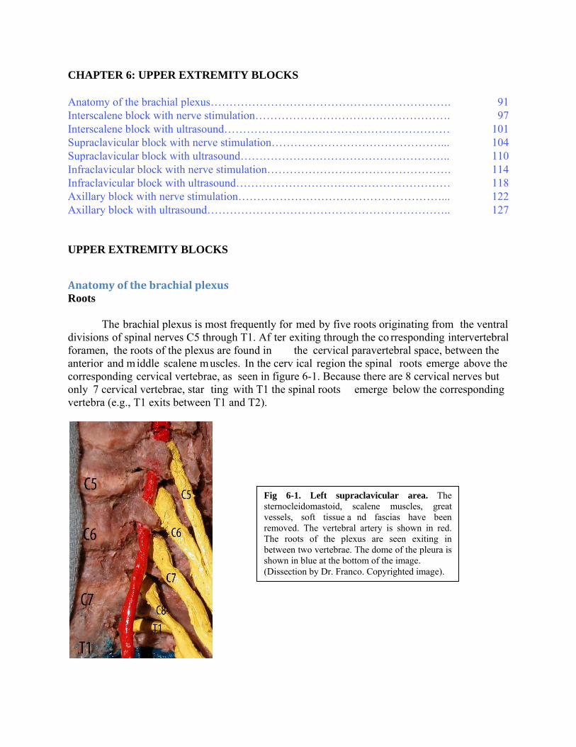
The brachial plexus is most frequently for med by five roots originating from the ventral divisions of spinal nerves C5 through T1. Af ter exiting through the co rresponding intervertebral foramen, the roots of the plexus are found in the cervical paravertebral space, between the anterior and middle scalene muscles. In the cerv ical region the spinal roots emerge above the corresponding cervical vertebrae, as seen in figure 6-1. Because there are 8 cervical nerves but only 7 cervical vertebrae, star ting with T1 the spinal roots emerge below the corresponding vertebra (e.g., T1 exits between T1 and T2).
Fig 6-1. Left supraclavicular area. The sternocleidomastoid, scalene muscles, great vessels, soft tissue a nd fascias have been removed. The vertebral artery is shown in red. The roots of the plexus are seen exiting in between two vertebrae. The dome of the pleura is shown in blue at the bottom of the image. (Dissection by Dr. Franco. Copyrighted image).

The distance from C5 to T1 roots is large and irreducible, and equal to the height of four
vertebrae. This fact in itself could help explain the frequent lack of dense anesthesia in the C8-T1 dermatomes after an injection perform ed at the level of the C5-C6 roots (interscalene block). Another important and frequently ignored reason is the expansive wave created by the pulse of the subclavian artery and felt m ostly by the dist al roots of the plexus (C8-T1), the lower trunk and its divisions. Because the local anesthetic diffuses to points of least resistance, this expanding pulsatile force may keep the local anesthetic from reaching the most distal elements of the plexus.
In addition to knowing the form ation of the plexus and its archit ecture throughout its trajectory, it is also important from my perspec tive to understand the plexus in term s of its relative surface area at different locations. The five roots occupy an area th at is elongated in the frontal plane, but very narrow in the sagittal plane (anteroposterior). W hen the five roots combine together to form three trunks, not only there is a 40% reduction in the number of nerve structures (from 5 to 3), but al so the trunks become physically contiguous, as shown in figure 6-2, helping reduce their com bined surface area. In fa ct this is the poin t at which the brachial plexus is reduced to its sm allest surface area. This striking convergence of innervation is unique to the brachial plexus and has no parallel in the lower extremity and helps explain the rapid onset and high success rate of the supraclavicular approach. The surface area of the plexus increases again when the trunks originate six divisions although they stay together so the small increase in surface area is com pensated by a larger su rface of absorpti on. The surface area in creases the most at the level of the axilla where the plexus gives off the terminal branches.
Thescalenemuscles
The anterior scalene muscle orig inates in the anterior tubercles of the transvers e processes of C3 to C6 and inserts o n the scalene tubercle of the superior aspect of the first rib. The middle scalene muscle originates in the posterior tubercles of the transverse processes of C2 to C7 and inserts on a large area of superior aspect of the first rib, behind the subclavian groove.
Fig. 6-2. Left supraclavicular area. The SCM, great vessels and fascias have been removed. The trunks (S, M, I) of the plexus are seen emerging in between the anterior scalene (AS) a nd medial scalene (MS). Also shown are the a nterior (a) and posterior (p) divisions of the upper trunk and its supraescapular branch (supr), the subclavian artery (SA) and vertebral artery (VA). (Dissection by Dr. Franco. Copyrighted image).
Brachial plexus structure: Trunks to terminal branches
The five roots converge toward each other to form three trunks -upper, middle and lower- stacked one on top of the other, as they traverse the triangular interscalene space formed between the anterior and middle scalene muscles. This space becomes wider in the anteropo sterior plane as the muscles approach their insertion on the first rib.
While the roots of the plexus are long, the trunks are alm ost as short (app 1cm ) as they are wide, soon giving rise to a tota l of six divisions (three anterior and three posterior), as they reach the clavicle. The area of the trunks corres ponds to the point where the b rachial plexus is confined to its sm allest surface area, three nerve stru ctures, closely related to o ne another, carrying the entire sensory, m otor and sympathetic innervation of the uppe r extremity, with the exception of a s mall area in the axilla and upper middle arm, which is innervated by the intercostobrachial nerve, a branch of the second in tercostal nerve. This great reduction in surface area allows the plexus to negotiate the narrow passage between the clavicle and the first rib at the apex of the axilla.
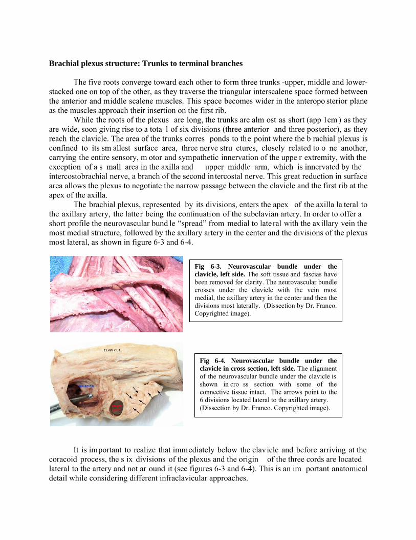
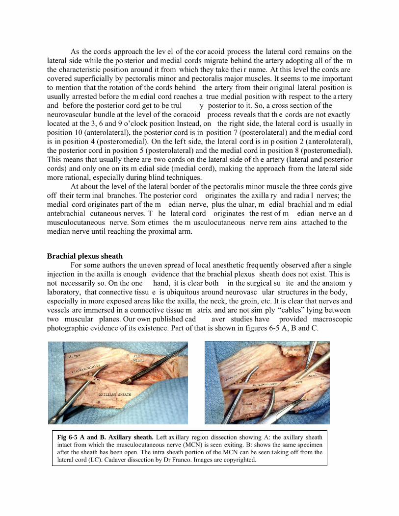
The brachial plexus, represented by its divisions, enters the apex of the axilla la teral to the axillary artery, the latter being the continuation of the subclavian artery. In order to offer a short profile the neurovascular bund le “spread” from medial to late ral with the ax illary vein the most medial structure, followed by the axillary artery in the center and the divisions of the plexus most lateral, as shown in figure 6-3 and 6-4.
It is important to realize that immediately below the clavicle and before arriving at the
coracoid process, the s ix divisions of the plexus and the origin of the three cords are located lateral to the artery and not ar ound it (see figures 6-3 and 6-4). This is an im portant anatomical detail while considering different infraclavicular approaches.
Fig 6-3. Neurovascular bundle under the clavicle, left side. The soft tissue and fascias have been removed for clarity. The neurovascular bundle crosses under the clavicle with the vein most medial, the axillary artery in the center and then the divisions most laterally. (Dissection by Dr. Franco. Copyrighted image).
Fig 6-4. Neurovascular bundle under the clavicle in cross section, left side. The alignment of the neurovascular bundle under the clavicle is shown in cro ss section with some of the connective tissue intact. The arrows point to the 6 divisions located lateral to the axillary artery. (Dissection by Dr. Franco. Copyrighted image).
As the cords approach the lev el of the cor acoid process the lateral cord remains on the lateral side while the po sterior and medial cords migrate behind the artery adopting all of the m the characteristic position around it from which they take thei r name. At this level the cords are covered superficially by pectoralis minor and pectoralis major muscles. It seems to me important to mention that the rotation of the cords behind the artery from their original lateral position is usually arrested before the m edial cord reaches a true medial position with respect to the a rtery and before the posterior cord get to be trul y posterior to it. So, a cross section of the neurovascular bundle at the level of the coracoid process reveals that th e cords are not exactly located at the 3, 6 and 9 o’clock position Instead, on the right side, the lateral cord is usually in position 10 (anterolateral), the posterior cord is in position 7 (posterolateral) and the medial cord is in position 4 (posteromedial). On the lef t side, the lateral cord is in p osition 2 (anterolateral), the posterior cord in position 5 (posterolateral) and the medial cord in position 8 (posteromedial). This means that usually there are two cords on the lateral side of th e artery (lateral and posterior cords) and only one on its m edial side (medial cord), making the approach from the lateral side more rational, especially during blind techniques.
At about the level of the lateral border of the pectoralis minor muscle the three cords give off their term inal branches. The posterior cord originates the axilla ry and radia l nerves; the medial cord originates part of the m edian nerve, plus the ulnar, m edial brachial and m edial antebrachial cutaneous nerves. T he lateral cord originates the rest of m edian nerve an d musculocutaneous nerve. Som etimes the m usculocutaneous nerve rem ains attached to the median nerve until reaching the proximal arm.
Brachial plexus sheath
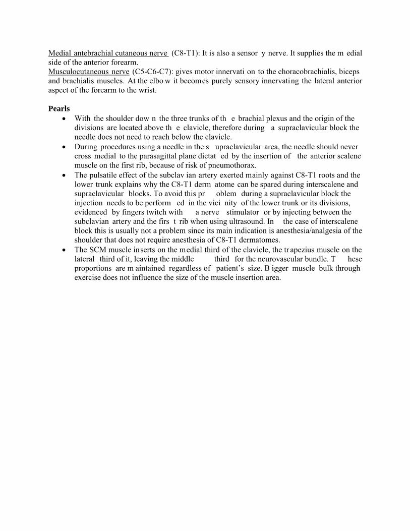
For some authors the uneven spread of local anesthetic frequently observed after a single injection in the axilla is enough evidence that the brachial plexus sheath does not exist. This is not necessarily so. On the one hand, it is clear both in the surgical su ite and the anatom y laboratory, that connective tissu e is ubiquitous around neurovasc ular structures in the body, especially in more exposed areas like the axilla, the neck, the groin, etc. It is clear that nerves and vessels are immersed in a connective tissue m atrix and are not sim ply “cables” lying between two muscular planes. Our own published cad aver studies have provided macroscopic photographic evidence of its existence. Part of that is shown in figures 6-5 A, B and C.
Fig 6-5 A and B. Axillary sheath. Left ax illary region dissection showing A: the axillary sheath intact from which the musculocutaneous nerve (MCN) is seen exiting. B: shows the same specimen after the sheath has been open. The intra sheath portion of the MCN can be seen taking off from the lateral cord (LC). Cadaver dissection by Dr Franco. Images are copyrighted.

Ultrasound, on the other hand, has confirm ed that nerves and vessels in all regions of the body, but especially in exposed p laces like the axilla, are em bedded in a m atrix of soft connective tissue contained within a fascial sheath. This loose connective tissue within the sheath absorbs the local anesthetic solution like a sponge, lim iting to some degree its free diffusion. In addition to this in ternal (within the sheath) factor, there are other factors outside the sheath that may also play a role on the spread of local anesthesia within it. An example is the pulsatile effect of the subclavian artery affecting the spread to C8-T1 levels in interscalene and supraclavicular blocks.
Distributionofthebranchesofthebrachialplexus Axillary nerve (C5-C6): gives an articular branch to the shoulder joint, motor innervation to the deltoid and teres minor muscles and sensory innervation to part of deltoid and scapular regions. Radial nerve (C5-C6-C7-C8): supplies the skin of th e posterior and late ral arm down to the elbow, the posterior forearm down to the wrist, lateral part of the dorsum of the hand and the dorsal surface of the first th ree and one-half fingers proximal to the nail beds. It also provides motor innervation to the triceps, anconeus, part of the brachialis , brachioradialis, extensor carpi radialis and all the ex tensor muscles of the poster ior compartment of the f orearm. Its injur y produces a characteristic “wrist drop”. Median nerve (C5-C6-C7-C8-T1): gives off no cutaneous or motor branches in the axilla or the arm. In the forearm it provides motor innervation to the anterior compartment except the flexor carpi ulnaris and the m edial half of the flexor digitorum profundus (ulnar nerve). In the hand provides motor innervation to the thenar em inence and the first two lumbricals. It provides the sensory innervation of the lateral half of the palm of the hand and dorsum of first three and one-half fingers including the nail beds. Ulnar nerve (C8-T1): like the m edian nerve, the ulnar nerve does not give off branches in the axilla or the arm. Its motor component supplies the flexor carpi ulnaris and the medial half of the flexor digitorum profundus. In the hand it provides the m otor supply to all the sm all muscles of the hand except the thenar em inence and first two lumbricals (median). Its sensory branches supply the medial third of the dorsum and palmar sides of the hand and dorsum of the 5th finger and dorsum of the medial side of 4th finger. Medial brachial cutaneous nerve (T1): it is solely a sensor y nerve. It supplies the skin of the medial side of the arm . It is joined here by the intercostobrachial nerve, branch of the second intercostal.
Fig 6-5 C. Axillary sheath in cross section. The axillary sheath just below the clavicle (apex) is shown with arrows as a well defined sturdy fascia surrounding the neurovascular bundle. The interior is o therwise filled with loose connective tissue. The three cords of the plexus (c) are shown lateral to the artery. Cadaver dissection by Dr Franco. Image is copyrighted.
Medial antebrachial cutaneous nerve (C8-T1): It is also a sensor y nerve. It supplies the m edial side of the anterior forearm. Musculocutaneous nerve (C5-C6-C7): gives motor innervati on to the choracobrachialis, biceps and brachialis muscles. At the elbo w it becomes purely sensory innervating the lateral anterior aspect of the forearm to the wrist. Pearls
With the shoulder dow n the three trunks of th e brachial plexus and the origin of the divisions are located above th e clavicle, therefore during a supraclavicular block the needle does not need to reach below the clavicle.
During procedures using a needle in the s upraclavicular area, the needle should never cross medial to the parasagittal plane dictat ed by the insertion of the anterior scalene muscle on the first rib, because of risk of pneumothorax.
The pulsatile effect of the subclav ian artery exerted mainly against C8-T1 roots and the lower trunk explains why the C8-T1 derm atome can be spared during interscalene and supraclavicular blocks. To avoid this pr oblem during a supraclavicular block the injection needs to be perform ed in the vici nity of the lower trunk or its divisions, evidenced by fingers twitch with a nerve stimulator or by injecting between the subclavian artery and the firs t rib when using ultrasound. In the case of interscalene block this is usually not a problem since its main indication is anesthesia/analgesia of the shoulder that does not require anesthesia of C8-T1 dermatomes.
The SCM muscle inserts on the medial third of the clavicle, the tr apezius muscle on the lateral third of it, leaving the middle third for the neurovascular bundle. T hese proportions are m aintained regardless of patient’s size. B igger muscle bulk through exercise does not influence the size of the muscle insertion area.

INTERSCALENE BLOCK NERVE STIMULATOR TECHNIQUE Indications
Its main indication is anesthesia or analgesi a of the shoulder, including the clavicle and proximal part of the humerus. Point of contact of the needle with the brachial plexus
The needle approaches the plexus at the level of the roots, high in the interscalene sp ace, approximately at the level of C5-C6 roots (most likely C5). Main characteristics
This block is superficial and usually easy to perform. Characteristically it misses the C8-T1 dermatomes, which include the sensory territories of ulnar, m edial antebrachial cutaneous, and medial brachial cutaneous nerves (medial side of the upper extremity). Patient position and landmarks
The patient is lightly sedated. Older, obese and recent trauma patients can be expected to be extremely sensitive to the depres sant effects of benzodiazepines and/or narcotics. Titrate to effect.
The patient is placed in a sem i sitting position and the spa ce between the cricoid and thyroid cartilages (cricothyroid m embrane) is located and marked as shown in figu re 6-6. The patient is asked to lower his shoulders and to sli ghtly rotate the head to the opposite side. It is important to emphasize here that the patient should rotate and not incline the head away so as to keep the midline neutral. With the midline in neutral position the intervertebral foram en looks caudal, lateral and slightly posterior. Tilting the head away from the operator, on the other hand, could align the intervertebral foramen with the needle trajectory.
A horizontal plane that starts at the cricothy roid membrane medially and intercepts the posterior border of the SCM laterally is established, as shown in figure 6-7.
Fig 6-6. Cricoid thyroid membrane. The level of the cricothyroid membrane is located by palpation and marked on the skin. (On a model with permission).

The index and m iddle fingers of the palpati ng hand are placed behind the SCM at this
level pushing it slightly forward (medially), as shown in figure 6-8. T his maneuver brings the palpating fingers under the SCM and on top (anterior) to the anterior scalene muscle. The fingers are then rolled back until they f all into the interscalene groove, which at this proximal point in the neck is a real structure and easy to identify. This is the point of needle insertion.
Type of needle
A 2.5 cm or 5cm, 22-G, insulated needle can be used.
Nerve stimulator settings The nerve stimulator is set to deliver a curre nt of 0.8-0.9 mA, at a pulse frequency of 1
Hz and pulse duration of 0.1 m sec (100 m icrosec). A sm all skin wheal is raised with 1% lidocaine or 1% mepivacaine using a small needle (ideally 27-G). Needle insertion
The needle is in troduced between the two pa lpating fingers in a m edial and slightly caudal direction, but m ost importantly with a 20 to 30-degree pos terior direction, as shown in figure 6-9.
Fig 6-8. Point of needle insertion. The interscalene groove is found at th e intersection of the cricoid plane with the posterior border of the SCM. (On a model with permission).
Fig 6-7. Cricoid-SCM plane. The level of the cricothyroid membrane is projected laterally to intercept the posterior border of the SCM. (On a model with permission).

It is important to realize that this is a superficial block th at should take place within the confines of the tips of the palpating f ingers and not beyond them. In no circumstance the needle should be introduced further than the projection of the clavicular head of the SCM.
Any distal motor twitch as well as biceps, triceps or deltoid muscles are adequate. There is some controversy in the lite rature as to whether a sh oulder twitch is acceptable for an interscalene block. Besides the usual arm twitches, anatomical and clinical evidence support accepting deltoid twitches. Motor twitches from trapezius (spinal accessory nerv e) and levator scapulae (dorsal scapular nerve) are not acceptab le. For further reading on this issue please see: Silverstein W et al. Interscalene block with a nerve stim ulator: A deltoid m otor response is a satisfactory endpoint f or successful block. Reg Anesth Pain Med 2000; 25:356-359 and accompanying editorial by William Urmey, same journal page 340-342.
A twitch of the abdomen signals phrenic nerv e stimulation and it is evidence that the needle is anterior to the anterior scalen e. In this cas e the needle sh ould be withdrawn and redirected slightly posteriorly. A motor twitch of the scapulae or trapezius muscle indicates that the position of the needle is too posterior and needs to be repositioned anteriorly.
Local anesthetic and volume
For single shot techniques in adults, 30 mL of 1.5% mepivacaine plain provides 2-3 h of anesthesia. The addition of 1:400,000 of epinephrine prolongs the anesthesia to about 3-4 h. The residual analgesia post anesthesia is variable in duration, although rarely persists for more than 2 h after block resolution. The addition of lyophilized tetracaine (20 mg per 10 mL of solution) to 1.5% mepivacaine, for a final con centration of 0.2% tetracaine, provides around 6 h of surgical anesthesia.
Ropivacaine or bupivacaine 0.5% p lus epinephrine 1:400,000 can be u sed in the sam e volume to provide 12 h plus of anesthesia. For more rapid onset and long duration we use 10 mL of 1.5% m epivacaine followed by 20 m L of 0. 5% ropivacaine or bupivacaine p lus 1:400,000 epinephrine.
For postoperative analgesia 20 mL of 0.2% ropivacaine can be used.
Side effects and complications Systemic local an esthetic reaction can occu r as with any block. Mo re specific (and
frequent) side effects related to in terscalene block are: Horner’s syndrome (ptosis, miosis and anhydrosis) due to stella te ganglion block and hoarseness due to recurrent laryngeal n erve involvement. Characteristically th is block produces also 100% of phrenic nerv e block with diaphragmatic paralysis (Urm ey et al, Anes th Analg, 1991). This can produce dyspnea and
Fig 6-9. Needle insertion. The needle is advanced medial, caudal and posterior. (On a model with permission).
reductions in respiratory volum es of up to 30%. Pneumothorax is possible, but rare with this block.
Clinical pearls
Because of the positio n of the shoulder, so close to the head of the patient, the anesthesiologist must carefully ev aluate the patient and surgeon before deciding to perform an interscalene block as the only anesthesia for the case. A nervous patient and a rough surgeon could be indications for interscalene analgesia com bined with general anesthesia.
It must be remembered that some of these procedures are performed in positions other than supine (e.g., beach chair, lateral), which can make the management of the airway, if needed, a bit more challenging.
A language barrier between patient and anesthesiologist is also a relative contraindication for interscalene block as the sole anesthetic.
This is a very superficial block that can be performed at 1-2 cm from the skin in most patients.

INTERSCALENE BLOCK ULTRASOUND TECHNIQUE Indications
Shoulder anesthesia and/or analgesia, including clavicle and proximal humerus.
Patient position The patient is placed semi seated, with the shoulder down and the head slightly turned the
opposite way, as shown in figure 6-10.
Type of needle A 2.5 cm or 5 cm, 22-G, insulated needle is what we frequently use.
Type of transducer This is a su perficial block for which a hi gh frequency (8-15 MHz) linear probe is well suited. Scanning
Two are the most frequent ways to scan the neck to visualize the roots of the plexus. One is to start a transverse scan over the sternocleidomastoid muscle (SCM) just lateral to the cricoid cartilage, or start more distally parallel to the clavicle and then trace the plexus proximally to the roots. In either case the probe ends in a semi transverse position (cephalad rotation) overlapping the SCM with a slight distal orientation as shown in figure 6-11.
The image obtained at this level is shown in figure 6-12.
Fig 6-10. Position. The patient is semi seated, with shoulder down and head slightly rotated to the opposite side. The ultrasound machine is placed on the opposite side. (On a model with permission).
Fig 6-11. Probe position. To get a good perpendicular cut of the roots, the probe is slightly rotated as s hown. (On a m odel with permission)

Needle insertion The needle can be advanced in plane from medial to lateral, or lateral to medial, or out of
plane usually from cephalad to caudal. It is our preference to insert the needle in p lane from lateral to medial as shown in figures 6-13 and 6-14.
This technique resembles Winnie’s classical interscalene approach. W ith the needle
under direct visualization the injection is perform ed in the proxim ity of C6 root. The spread of local anesthetic should expand the interscalene space and bathe C5-C6 and C7 roots, as shown in figure 6-14. If the sp read is insuf ficient around a par ticular root the needle is re positioned accordingly for a new injection. Local anesthetic and volume We use between 20-30 mL of local anesthetic of the same kind used for nerve stimulation techniques. Side effects and complications
Fig 6-12. Interscalene image. With the probe in the position shown in fig 6-11 it is p ossible to visualize part o f the SCM, ant and m iddle scalene m uscles and the proximal roots of the plexus. (Author’s archive)
Fig 6-13. Needle insertion. The needle is in troduced in plane from lateral to medial. (On a m odel with permission)
Fig 6-14. US image. Vertical arrows show the needle while the two horizontal arrows show part of the hypoechoic spread of local anesthetic around the plexus roots. (Author’s archive)

The side effects and com plications are essentially the same described for nerve stimulation techniques. It is pos sible that ultrasound techniques, w ith a more targeted injection and potentially smaller volumes, may theoretically decrease the incidence of side effects, but this remains to be proven.
SUPRACLAVICULAR BLOCK NERVE STIMULATOR TECHNIQUE Indications
This block is indicated for any surgery on the upper extremity distal to the shoulder or for analgesia of the entire upper extremity. Point of contact of the needle with the brachial plexus
The needle approaches the plexus at th e level of the trunks, and ideally the inje ction should take place in the vicinity of the lower trunk. Main characteristics
This block is considered by som e as more difficult to learn than other upper extremity blocks and historically it has be en associated with a high er risk of pneumothorax. The literature cites pneumothorax rates between 0.5-6.1 percen t. However with good anatom y and meticulous technique we have been able to practically eliminate this risk.
A supraclavicular block is us ually associated with a short onset, dens e anesthesia and high success rate. As we discussed it in the an atomy section, this is due to the com pact arrangement of the plexus at the level of tr unks and divisions. Because of these favorable characteristics, the supraclavicular block has been called the “spinal of the upper extremity”.
We perform our own variation of the supraclavicular block, a very anatomical approach that starts by determining the pleura boundaries as the first step. This allows us to take advantage of such extraordinary block while limiting its potential drawbacks. Our e xperience to late 2009 includes more than 5,000 supracla vicular blocks without ever having demonstrated a single pneumothorax. A common question posed to us is whether we perform routine chest X-rays after a supraclavicular block. The answer is no. In fact we only do an X-ray when the clinical situation merits it (e.g., an unusually difficult technique and or sym ptomatic patient). Traditionally our anesthesiology textbooks have left the impression that a pneumothorax following a supraclavicular block has a late onset, m aking the technique a bad choice for outpatients. Our review of the lite rature fails to demonstrate this. In f act most of the cases of pneumothorax associated with supraclavicular block published in the literature, have been diagnosed within a few hours after the block and most of them have been investigated because of the patients’ early symptoms. We perform this technique with great success in all kinds of patients, including sam e day surgery and trauma patients.
SomehistoryofthesupraclavicularapproachThe supraclavicular block was introduced into clinical practice in Ger many by
Kulenkampff in 1911. A publication of his technique appeared later in the English literature in 1928. Kulenkampff accurately described the plexus as being m ore compacted in the neighborhood of the subclavian ar tery, where he rightly believed that a single injection could provide adequate anesthesia of the entire upper extrem ity. Kulenkampff’s technique was simple and in many ways sound. Unfortunately his reco mmendation to introduce the needle toward the first rib, in the direction of the spinous proce ss of T2 or T3, carried an inherited risk for pneumothorax that would be responsible for the technique falling into disfavor.
Albeit with several modifica tions, the supraclavicular ap proach remained a po pular choice until the early 1960’s. Eventually, the co mbined effect of pneumothorax fear and the
introduction of the axi llary approach by A ccardo and Adrian i in 1949, and especially by Burnham in 1958, marked the beginning of the decline for one of the best approaches in regional anesthesia.
The axillary approach introduced a good techni que with its share of shortcom ings (e.g., smaller area of anesthes ia than supraclavicular, tendency to produce “pat chy” blocks and lower overall success rate), but defini tely devoid of pneum othorax risk. The axillary block received a big push when in 1961 De Jong published an articl e in Anesthesiology praising it. His paper was based on cadaver dissections and included the no w famous calculation of 42 m L as the volum e needed to fill a cylinder 6 cm long that, ac cording to De Jong, “s hould be sufficient to completely bathe all branches of the brachial plexus”. Coincidentally (or not) the sam e journal issue carried a paper by Brand and Papper out of New York, com paring axillary and supraclavicular techniques in their hands. This article is the source of the 6.1% pneum othorax rate frequently quoted for supraclavicular block. The authors were determined to prove tha t the axillary block was safer and better than the supraclavicular block. They succeeded by not only producing the highest percentage of pneumothorax (6.1%), but the highest number (14 cases) for an individual study. This study should be considered an aberration.
In retrospect these two articles could be considered the turning point at which the axillary route became the preferred approach here in th e United States and the rest of the world. W ith some exceptions this is still true to day. Fortunately ultrasound in regional anesthesia has caused a renewed interest in this approach and we could not be happier.
The supraclavicular technique with its rapid onse t, density, high success rate along with large area of anesthesia are hi ghly desirable. These good characteri stics are, according to David Brown and colleagues, “unrivaled” by other tec hniques. In our practice the sup raclavicular approach is the cornerstone of upper extremity regional anesthesia. Patient position and landmarks
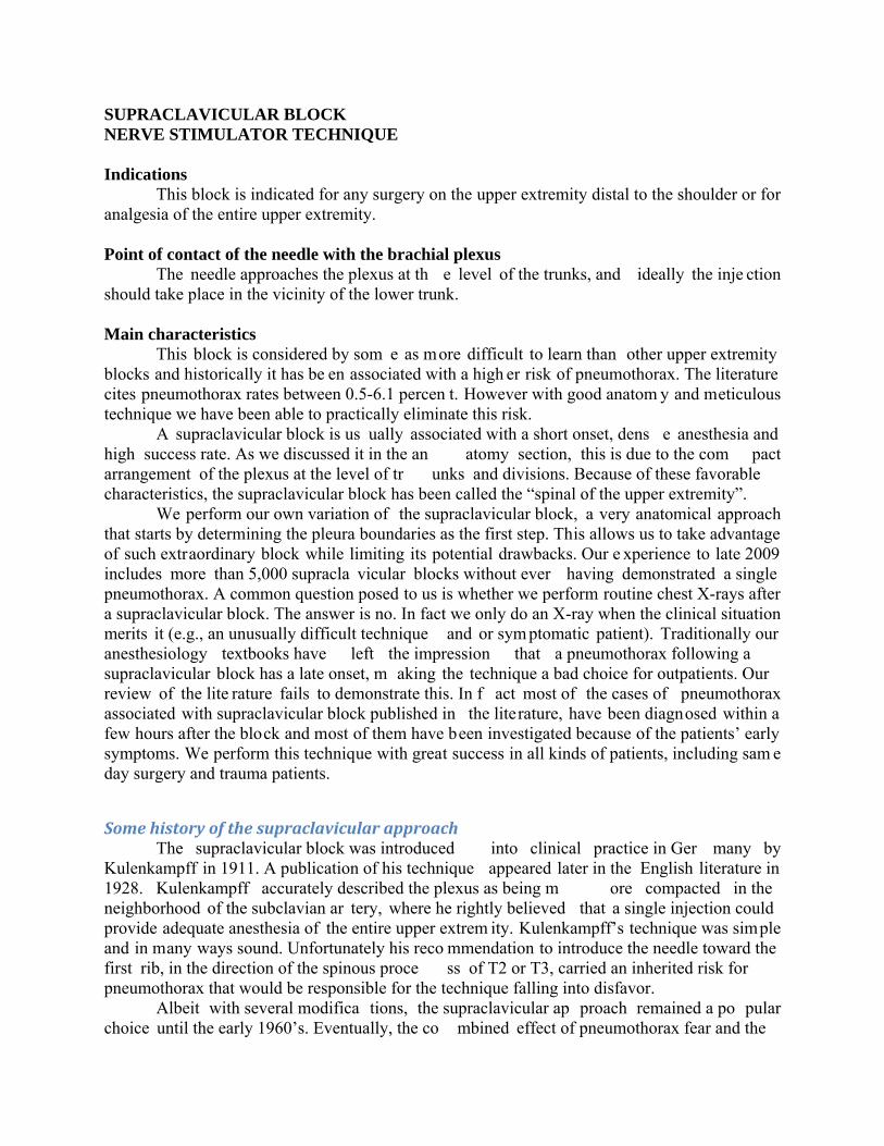
The patient lies in the s emi sitting position, the ipsilateral shoulder down and the head turned to the opposite side, as shown in figure 6-15. The arm to be blocked is flexed at the elbow and, if possible, the wrist is supinated to easily detect a twitch of the fingers.
The point at which the clavicu lar head of the SCM muscle inserts in the clavicle is then
identified, as shown in fig 6-16. A parasagittal (para llel to the m idline) plane at this level determines an “unsafe” zone m edial to it, wher e the risk of pneum othorax is high and a lateral zone that is safer.
Fig 6-15. Patient position. The patient is semi seated with the head of the be d elevated 30 degrees. The head of the patient is tu rned away, th e shoulder is down and the arm is flexed a t the elbow and supinated at the wrist. (On a model with permission).

Because the trunks are short and run in a very steep direction caudally towards the clavicle, there is a narrow “window of opportunity ” to perform the block above the clavicle. It must be performed at enough distance from the insertion of the SCM on the clavicle to be safely away from the pleural dome, but not too far to miss the trunks and the plexus completely. We call this distance “the safety m argin”. In adults we calculate this distance to be about 1 inch (2. 5 cm), which corresponds to the width of the autho r’s thumb. This distance is m arked on the skin over the clavicle for orientation, as shown in figure 6-17.
This is only an orientation point that usually will coincide with the m idpoint of the clavicle in an adult patient. At this level the brachial plexus is usually easily palpable, either as a groove or as som e type of bum p(s). This is usually called “intersc alene groove”, but the interscalene groove only exists high in the C5-C6 level. The groove is lost more distally as the scalene muscles diverge from each other in the fr ontal and sagittal p lanes. The palpation of the plexus is w hat determines the actual point of needle entrance and not a fixed distance. The plexus can be palpated a few mm medial or lateral to the orientation point, but never too far from it.
The palpating finger is p laced parallel to the cl avicle and the point of needle en trance is located immediately cephalad to it, as shown in figure 6-18.
Fig 6-16. Lateral head of SCM. The most lateral in sertion of th e SCM on the clavicle is found and marked with an arrow. Crossing this plane medially increases the risk of pneum othorax. (On a model with permission).
Fig 6-17. Safety margin. A safety margin of 1” (2.5 cm) lateral to the insertion of the SCM on the clavicle is marked on the skin. (On a model with permission).
Fig 6-18. Orientation arrows. The medial arrow pointing up shows the lateral in sertion of SCM (pleura’s lateral b oundary). The lateral arro w pointing caudally shows the needle entrance point. The two lateral arrows poi nting at each othe r show the needle trajectory (parallel to the patient’s midline). (On a model with permission).
Type of needle
A 5cm, 22-G, insulated needle is used for this technique.
Nerve stimulator settings The nerve stimulator is set to deliver a cu rrent of 0.8-0.9 mA, at a pulse frequency of 1
Hz and pulse duration of 0.1 m sec (100 m icrosec). A sm all skin wheal is raised with 1% lidocaine or 1% mepivacaine using a small needle (ideally 27-G). Needle insertion
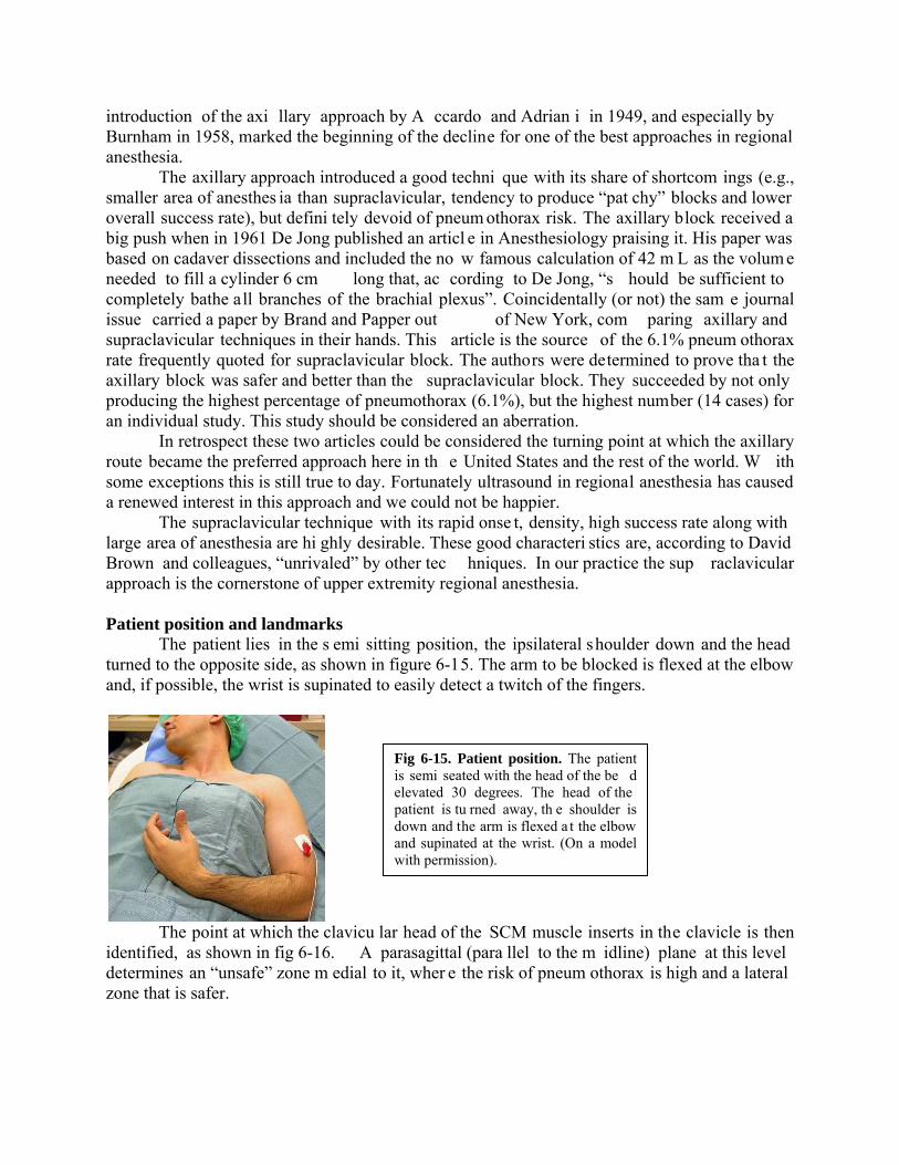
The needle is inse rted first anteroposterior (toward the bed) with a 30 degree caudal orientation, as shown in figure 6-19, for a distance of a few mm and up to 1.5 cm , depending on the amount of subcutaneous tissue. After a shor t distance, a twitch of the upper trunk (shoulder) is usually found as evidence that the needle is approaching the frontal plane of the plexus.
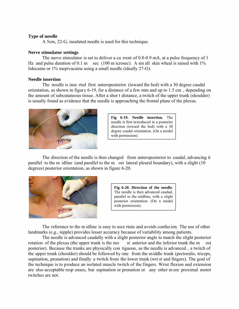
The direction of the needle is then changed from anteroposterior to caudal, advancing it parallel to the m idline (and parallel to the m ost lateral pleural boundary), with a slight (10 degrees) posterior orientation, as shown in figure 6-20.
The reference to the m idline is easy to asce rtain and avoids confus ion. The use of other landmarks (e.g., nipple) provides lesser accuracy because of variability among patients.
The needle is advanced caudally with a slight posterior angle to match the slight posterior rotation of the plexus (the upper trunk is the mo st anterior and the inferior trunk the m ost posterior). Because the trunks are physically con tiguous, as the needle is advanced , a twitch of the upper trunk (shoulder) should be followed by one from the middle trunk (pectoralis, triceps, supination, pronation) and finally a twitch from the lower trunk (wri st and fingers). The goal of the technique is to produce an isolated muscle twitch of the fingers. Wrist flexion and extension are also acceptable resp onses, but supination or pronation or any other m ore proximal motor twitches are not.
Fig 6-19. Needle insertion. The needle is first in troduced in a posterior direction (toward the bed) with a 30 degree caudal orientation. (On a model with permission).
Fig 6-20. Direction of the needle. The needle is then advanced caudad, parallel to the midline, with a slight posterior orientation. (On a model with permission).
If after advancing the needle the motor twitch of the shoulder disappears and no twitch is elicited from the middle trunk, it usually means that the angle of insertion of the needle is not matching the orientation of the trunks, and that th e tip of the needle is wandering aw ay from the trunks (usually anteriorly). The needle should be slowly withdrawn until th e original twitch is elicited once again, and then redirected either posteriorly (most of the times) or anteriorly, but always parallel to the midline.
It is very important not to advance the needle more than 2 cm in the caudal direction if no twitch is visible. In this case the situation should be reassessed starting with the nerve stimulator and its connections and determ ination of landmarks. On the other hand, when a twitch from the brachial plexus is being elicited the depth of n eedle insertion is le ss important as such m otor twitch reveals that the needle is still in close proximity to the plexus. Local anesthetic and volume
For single shot techniques in adults, 30 mL of 1.5% mepivacaine plain provides 2-3 h of anesthesia. The addition of 1:400,000 of epinephrine prolongs the anesthesia to about 3-4 h. The residual analgesia post anesthesia is variable in duration, although rarely persists for more than 2 h after block resolution. The addi tion of lyophilized tetracaine (20 mg per 10 mL of solution) to 1.5% mepivacaine, for a final con centration of 0.2% tetracaine, provides around 6 h of surgical anesthesia.
Ropivacaine or bupivacaine 0.5% p lus epinephrine 1:400,000 can be u sed in the sam e volume to provide 12 h plus of anesthesia. For more rapid onset and long duration we use 10 mL of 1.5% m epivacaine followed by 20 m L of 0. 5% ropivacaine or bupivacaine plus 1:400,000 epinephrine.
For postoperative analgesia 20 mL of 0.2% ropivacaine can be used.
Sideeffectsandcomplications
Besides the common com plications accompanying any block, the supraclavicula r technique can also be followed by Horner’s s yndrome, hoarseness and phrenic nerve palsy, but less frequently than after interscalene block. Neal et al in 1998 studied diaphragmatic paralysis in 8 volunteers after supraclavicula r block using ultrasound (replicati ng what Urmey et al did in 1991 to demonstrate 100% of diaphragm atic paralysis after interscalene block). They found an incidence of 50% of diaphragm atic paralysis. No s ubject experienced changes in pulm onary function tests (PFTs) or subjective symptoms of respiratory difficulty. This is our experience too.
In the issue of pneum othorax, I already mentioned that the literature cites a risk of 0.5% to 6.1%, the latter being an ab erration. A careful and m eticulous technique should carry a minimal risk of pneumothorax. In our long experience including thousands of cases in all sorts of patients we have never demonstrated a case of pneumothorax.
Clinicalpearls
This is not a block for a practitioner that rarely performs peripheral nerve blocks. The person interested in learning to perform it should first beco me familiar with the anatomy of the supraclav icular area in cluding the location of the dome of the pleura. U sing ultrasound makes the visualization of the pleura easier, but s till requires the operator to be familiar with the anatomy of the area.

When using a nerve stimulator technique, the block should not be attem pted unless the insertion of the sternocleidomastoid in the c lavicle is clearly established. In fact this is a must especially for a person not ex perienced with the te chnique. With time it becomes easier to ascertain the boundaries of the SCM.
It helps to know that the neurovascular bundl e crosses the clavicle under the m idpoint of it, so this should be kept in mind as a reliable reference.
Due to the steep direction of the plexus from the neck to the axilla, the higher in the neck (the further away from the clavicle) the more medial the plexus is. By the same token, the further below the clavicle the more lateral to its midpoint the plexus is.
The needle should never be inserted m ore than 2 cm caudal if no twitch is elicited. This warning applies to every patient regardless of weight.
The injection should always be slow, alternated with frequent and gentle aspirations. This technique provides time to recogn ize accidental intravascular injection in those cases where blood is not aspirated. I also believe it helps to keep the needle from moving backwards as a result of high speed flow at the tip of the needle.
SUPRACLAVICULARBLOCK
ULTRASOUNDTECHNIQUE Indications Anesthesia and/or analgesia for any procedure on the uppe r extremity distal to the shoulder. Patient position
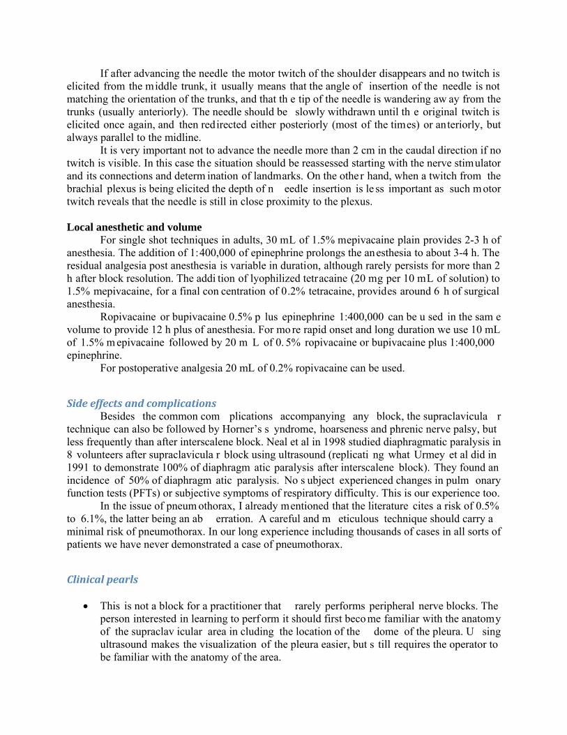
The patient is placed in the semi seated position as shown in figure 6-21.
Type of needle
A 5cm, 22-G, insulated needle is used.
Type of transducer This is also a superficial block for which a high frequency (8-15 MHz) is used.
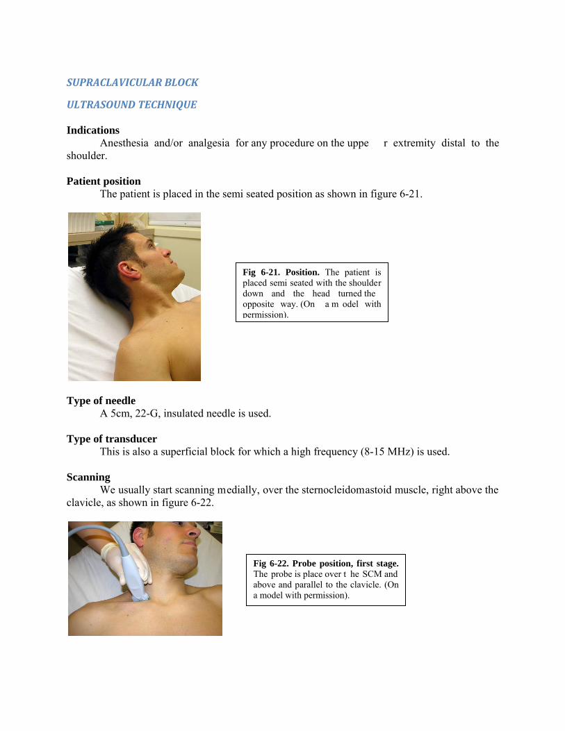
Scanning We usually start scanning medially, over the sternocleidomastoid muscle, right above the
clavicle, as shown in figure 6-22.
Fig 6-21. Position. The patient is placed semi seated with the shoulder down and the head turned the opposite way. (On a m odel with permission).
Fig 6-22. Probe position, first stage. The probe is place over t he SCM and above and parallel to the clavicle. (On a model with permission).

At this level we get to see the dom e of the pleura and above it, the subclavian vein at that point where it is joining the internal jugular vein to form the brachiocephalic vein, as shown in figure 6-23.
The probe is then slid laterally towards the midpoint of the clavicle, as shown in figure 6-
24,
At this leve l a cro ss section of the subclavian artery, the first rib and plexus can be visualized, as shown in figure 6-25.
Fig 6-23. Scanning, first image. With the probe over the SCM the subclavian vein and pleural dome can be visualized. (Author’s archive).
Fig 6-24. Probe position, second stage. The probe is moved laterally to visualize the p lexus as it p asses over the 1st rib. (On a model with permission).
Fig 6-25. Scanning the plexus above the clavicle. The subclavian artery (SA) is s een above the first rib, which is shown with three arrows pointing up. A small arrow pointing down shows the pleura while the larger single arrow shows the position of the divisions of the plexus. (Author’s archive).
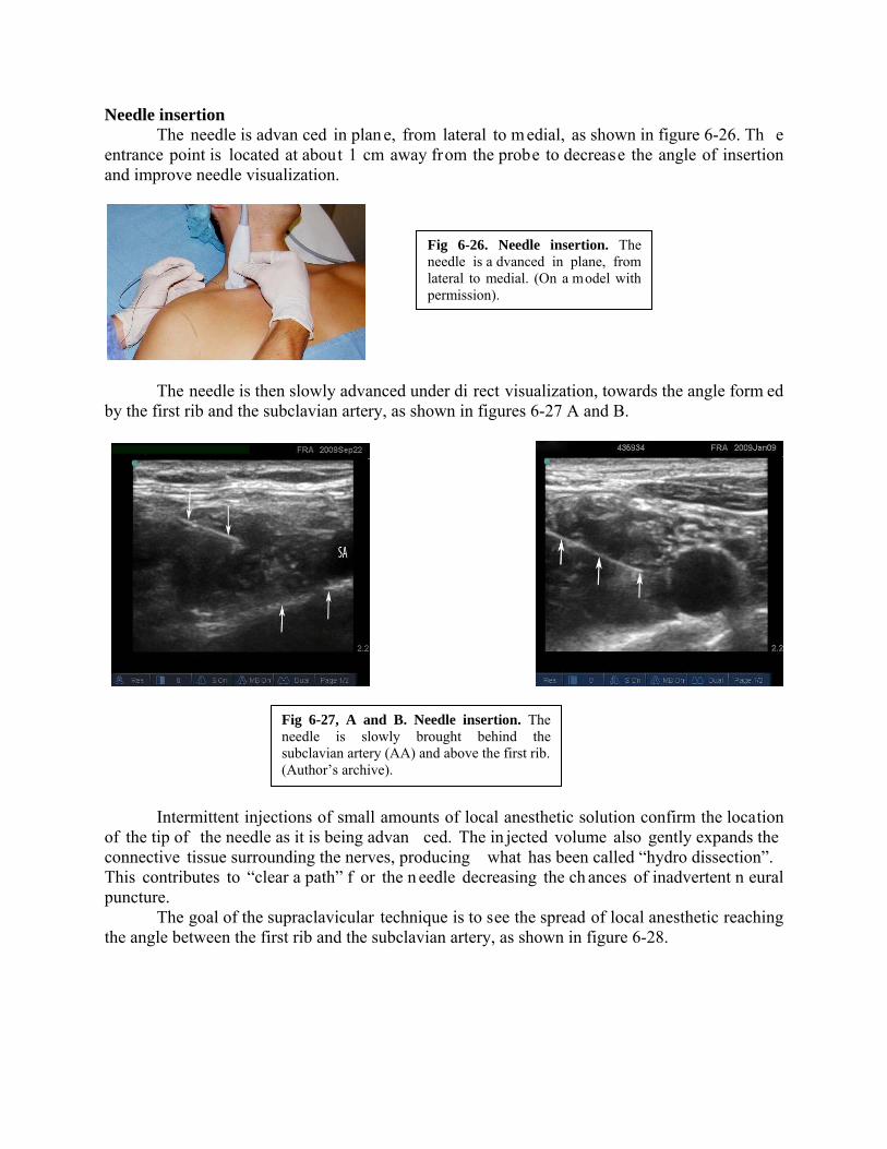
Needle insertion The needle is advan ced in plan e, from lateral to m edial, as shown in figure 6-26. Th e
entrance point is located at about 1 cm away from the probe to decrease the angle of insertion and improve needle visualization.
The needle is then slowly advanced under di rect visualization, towards the angle form ed by the first rib and the subclavian artery, as shown in figures 6-27 A and B.
Intermittent injections of small amounts of local anesthetic solution confirm the location of the tip of the needle as it is being advan ced. The in jected volume also gently expands the connective tissue surrounding the nerves, producing what has been called “hydro dissection”. This contributes to “clear a path” f or the n eedle decreasing the ch ances of inadvertent n eural puncture.
The goal of the supraclavicular technique is to see the spread of local anesthetic reaching the angle between the first rib and the subclavian artery, as shown in figure 6-28.
Fig 6-26. Needle insertion. The needle is a dvanced in plane, from lateral to medial. (On a model with permission).
Fig 6-27, A and B. Needle insertion. The needle is slowly brought behind the subclavian artery (AA) and above the first rib. (Author’s archive).

LocalanestheticandvolumeFor single shot techniques in adults, 30 mL of 1.5% mepivacaine plain will provide 2-3 h
of anesthesia. The addition of 1:400,000 epinephrin e prolongs the anesthesia to about 3-4 h. The residual analgesia post anesthesia is variable in duration, although it rarely persists for more than 2 h after block resolution. Th e addition of 2 m g/mL of l yophilized tetracaine to 1.5% mepivacaine, for a final concentration of 0.2% tetracaine, prolongs the duratio n of surgical anesthesia to 4-6 hours.
For longer anesthesia/analgesia 30 mL of 0.5% ropivacaine or bupivacaine can pro vide more than 12 h of anesthesia, although the onset is delayed to 20-30 min. If a more rapid onset is needed we use 5-10 mL of 1.5% m epivacaine followed by 20 m l of 0.5% ropivacaine o r bupivacaine. We always add epinephrine 1:400,000 as intravascular marker.
Also 20-30 mL of 0.2% ropivacaine can be us ed to provide postoperative analgesia for surgery performed under general anesthesia.
Fig 6-28. Injection. The local anesthetic spread should be seen reaching the angle formed by the 1st rib (vertical arrows pointing up) and the subclavian artery (SA). The local anesthetic is seen as a hypoechoic (dark) shadow projecting from the tip of the needle. (Author’s archive).

INFRACLAVICULAR BLOCK NERVE STIMULATOR TECHNIQUE Indications
This block can prov ide anesthesia/analgesia of a large area of the u pper extremity including the elbow, especially if performed proximally near th e apex of the axilla. It is considered a good approach for continuous techniques because it offers more stability than other more mobile locations. Point of contact of the needle with the brachial plexus
The needle approaches the plexu s at the level of the cords, or even divisions if the block is performed proximally, closed to the clavicle. Main characteristics
The infraclavicular block could be considered an axilla ry block in which th e needle enters the axilla through its anterior wall (pectoralis m uscles), instead of through its base. The infraclavicular space of the anesthesiologists corresponds to pa rt of the axillar y pyramid of the anatomists. With the arm in adduction it is represented on the skin by a triangular area whose base is superior (clavicle), a m edial wall formed by the projecti on on the skin of the thorac ic cage and a lateral wall form ed by the m edial side of the upper arm . Depending on the patient’s amount of subcutaneous tissue an d/or muscle this block can be deep. Patients should be adequately sedated.
It is widely recomm ended when using a nerve stimulator to obtain a dis tal twitch in the hand or wrist and to avoid either a biceps twitc h (musculocutaneous nerve or lateral cord) or pronation of the forearm (lateral cord). This re commendation is based on clinical experience. A biceps twitch could be the result of musculocutaneous nerve stim ulation, outside the sheath, or from lateral cord stimulation ins ide the sh eath. Because the operator can not accurately distinguish one from the other, this response is unreliable.
It is likely that a twitch from the poster ior cord (elbow, wrist and or f inger extension) could be best, because the posteri or cord is loc ated at about the same distance from the other two, and th e spread of local anes thetic from this central location m ight be m ore even. There could be another good reason to inject behind the artery, although it may be more difficult to get there. Because the posterior structures (including the posterior cord) are more closely packed, the spread of local anesthetic from anterior to posterior may be more difficult than from posterior to anterior. Ultrasound, with visualization of the ax illary artery and the cords around it, m akes this injection easier to accomplish.
Different infraclavicular tec hniques have been described. A simple technique is the coracoid approach first described by W hiffler in the British Journal of Anaesthesia in 1981 and later redefined by MRI studies performed in 40 volunteers by Wilson, Brown et al, and published in Regional Anesthesia in 1998. This is the tech nique we most frequently perform when using nerve stimulation.
PatientpositionandlandmarksThe patient is placed sem i seated with the ipsilateral shoulder down. The arm is slightly
abducted 30-45 degrees, as shown in figure 6-29, to bring the neurovascular bundle away from the thoracic cage and decrease the chance of pneumothorax.
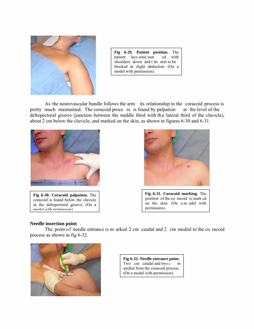
As the neurovascular bundle follows the arm its relationship to the coracoid process is pretty much maintained. The coracoid proce ss is found by palpation at the level of the deltopectoral groove (junction between the middle third with th e lateral third of the clavicle), about 2 cm below the clavicle, and marked on the skin, as shown in figures 6-30 and 6-31.
Needle insertion point The point o f needle entrance is m arked 2 cm caudal and 2 cm medial to the co racoid
process as shown in fig 6-32.
Fig 6-32. Needle entrance point. Two cm caudal and two c m medial from the coracoid process. (On a model with permission).
Fig 6-29. Patient position. The patient lays semi seat ed with shoulders down and t he arm to be blocked in slight abduction. (On a model with permission).
Fig 6-30. Coracoid palpation. The coracoid is found below the clavicle in the deltopectoral groove. (On a model with permission).
Fig 6-31. Coracoid marking. The position of the co racoid is mark ed on the skin. (On a m odel with permission).

Type of needle It is possible to use sometimes a 5cm, 22-G insulated needle, but a 10cm, 21-G insulated needle is usually necessary.
Nervestimulatorsettings
Thenervestimulatorissettodeliveracurrentof0.8‐0.9mA,pulsefrequencyof1Hzandpulsedurationof0.1msec(100microsec).
NeedleinsertionThe needle attached to the ne rve stimulator is advanced in the anteroposterior direction,
towards the bed, as shown in figure 6-33.
Before entering in contact with the plexus th e needle passes through pectoralis major and pectoralis minor muscles producing a visible local twitch. The brac hial plexus is found deep to them. If not response from the plexus is obtained, the needle is redirected caudal (most of the times) or cephalad, but m aintaining the same pa rasagital plane without medial or lateral deviation.
LocalanestheticandvolumeThe nerve stimulator-guided infraclavicular technique usually requires a relatively high
volume of l ocal anesthetic for better results. Usually 40 mL of 1.5% m epivacaine plain will provide 2-3 h of anesthesia. The addition of 1:400,000 epinephrine prolongs the anesthesia to about 3-4 h. The residual analgesia post anesthesia is variable in duration, although it rarely persists for m ore than 2 h after block resolution. The addi tion of 2 m g/mL of lyophilized tetracaine to 1.5% m epivacaine, for a final c oncentration of 0.2% te tracaine, prolongs the duration of surgical anesthesia to 4-6 hours.
For longer anesthesia/analgesia 30 mL of 0.5% ropivacaine or bupivacaine can pro vide more than 12 h of anesthesia, although the onset is delayed to 20-30 min. If a more rapid onset is needed we use 5-10 mL of 1.5% m epivacaine followed by 20 m l of 0.5% ropivacaine o r bupivacaine. We always add epinephrine 1:400,000 as intravascular marker.
Fig 6-33. Needle insertion. The needle is introduced from anterior to posterior. (On a model with permission).

Ropivacaine 0.5% can be used in the same volume for more than 12 h of anesthesia. Also 20-30 mL of 0.2% ropivacaine can be used to provide postoperative analgesia for surgery performed under general anesthesia.
SideeffectsandcomplicationsMuscle pain and hematomas, which can be large in size, can happen. Pneum othorax can
occur due to injury of the pleura through an intercostal space.
Clinicalpearls
This is a good place to put a catheter because it is easier to fix it. Use adequate sedation, as this block is m ore uncomfortable for patients than other more
superficial blocks. The junction between lateral and middle third of the clavicle can be used to locate the
deltopectoral groove and the coracoid process. Placing the arm in slight abduction (30-40 degrees) brings the neurovascular bundle away
from the thoracic cage (it follows the arm) and decreases the chance of pneumothorax.
INFRACLAVICULARBLOCK
ULTRASOUNDTECHNIQUE Indications The same indications m entioned for ne rve stimulation techniques, basically anesthesia/analgesia of elbow, forearm wrist and hand. Two main infraclavicular techniques Ultrasound introduces a degree of flexibility to our techniques of regional anesthesia that we did not have before. It certainly gives the operator the chance to choose the best needle path based on the anatomy and the ultrasound image obtained, without necessarily having to conform strictly to any particular technique already described.
When using ultrasound in the in fraclavicular area I distingu ish two main approaches, a proximal one just under the clavicle and a more distal one at the level of the coracoid process. As I mentioned in the anatom y section, the brachial plexus crosses under the clavicle as divisions before forming th ree cords. The divisions and the proxim al trajectory of the cords below th e clavicle are located la teral to the axillary artery. When the cord s approach the coracoid process they rotate and surround the artery to take the position from which they get their names.
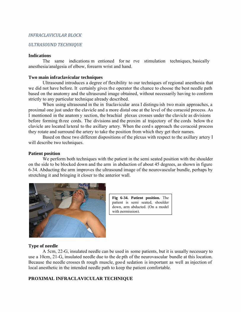
Based on these two different dispositions of the plexus with respect to the axillary artery I will describe two techniques. Patient position We perform both techniques with the patient in the semi seated position with the shoulder on the side to be blocked down and the arm in abduction of about 45 degrees, as shown in figure 6-34. Abducting the arm improves the ultrasound image of the neurovascular bundle, perhaps by stretching it and bringing it closer to the anterior wall.
Type of needle A 5cm, 22-G, insulated needle can be used in some patients, but it is usually necessary to use a 10cm, 21-G, insulated needle due to the de pth of the neurovascular bundle at this location. Because the needle crosses th rough muscle, good sedation is important as well as injection of local anesthetic in the intended needle path to keep the patient comfortable. PROXIMAL INFRACLAVICULAR TECHNIQUE
Fig 6-34. Patient position. The patient is semi seated, shoulder down, arm abducted. (On a model with permission).

Type of transducer Depending on the thickness of th e patient’s chest wall the operator can use a linear high
frequency (8-15 MHz) probe or a curved low frequency (3-7 MHz) one.
Scanning For this more proximal approach we place the transducer parallel and immediately below to the midpoint of the clavicle, as shown in figure 6-35.
The image obtained at this prox imal level is a cross section of the neurovascular bundle as it aligns under the clavicle in a form ation that has the axilla ry vein as the most m edial structure, followed by the axillary arte ry in th e center and the divisions of the plexus m ost laterally, as shown in figure 6-36.
Needle insertion The needle can be advanced out of plane fr om caudal to cephalad, but we usually prefer an in plane technique from lateral to medial, as shown in figure 6-37.
Fig 6-35. Proximal scanning, left side. The transducer is placed parallel to the midpoint of the clavicle and immediately below it. (On a model with permission).
Fig 6-36. Proximal scanning, left side. At this proximal level pectoralis major (Pec major) is the main muscle seen superficial to the neurovascular bundle. Pectoralis minor is located distally to this US sect ion. Among the neurovascular bundle structures the axillary vein (AV) is the most medial, followed by the axillary artery (AA) and then the divisions of the plexus most laterally. (Author’s archive).
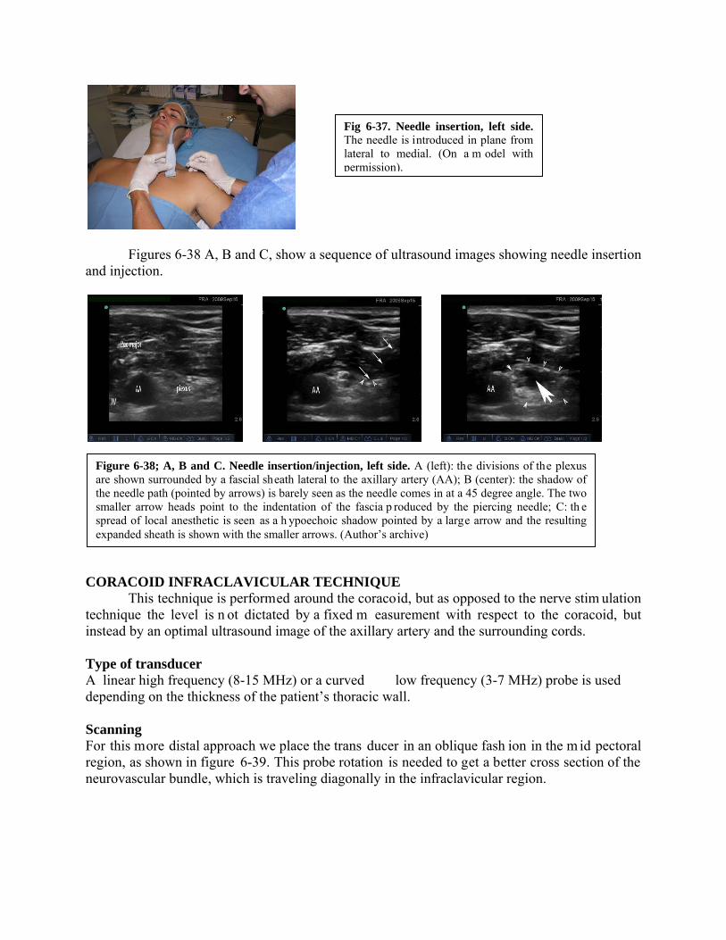
Figures 6-38 A, B and C, show a sequence of ultrasound images showing needle insertion and injection.
CORACOID INFRACLAVICULAR TECHNIQUE
This technique is performed around the coracoid, but as opposed to the nerve stim ulation technique the level is n ot dictated by a fixed m easurement with respect to the coracoid, but instead by an optimal ultrasound image of the axillary artery and the surrounding cords. Type of transducer A linear high frequency (8-15 MHz) or a curved low frequency (3-7 MHz) probe is used depending on the thickness of the patient’s thoracic wall. Scanning For this more distal approach we place the trans ducer in an oblique fash ion in the m id pectoral region, as shown in figure 6-39. This probe rotation is needed to get a better cross section of the neurovascular bundle, which is traveling diagonally in the infraclavicular region.
Fig 6-37. Needle insertion, left side. The needle is introduced in plane from lateral to medial. (On a m odel with permission).
Figure 6-38; A, B and C. Needle insertion/injection, left side. A (left): the divisions of the plexus are shown surrounded by a fascial sheath lateral to the axillary artery (AA); B (center): the shadow of the needle path (pointed by arrows) is barely seen as the needle comes in at a 45 degree angle. The two smaller arrow heads point to the indentation of the fascia p roduced by the piercing needle; C: th e spread of local anesthetic is seen as a h ypoechoic shadow pointed by a large arrow and the resulting expanded sheath is shown with the smaller arrows. (Author’s archive)

The ultrasound im age obtained at this level is shown in figure 6-40. At this level the cords of the plexus have already rotated behind the axillary artery and adopted their arrangement around it from which they take their names, medial, posterior and lateral.
Needle insertion As it is the case with the more proximal approach, the needle can be inserted out of plane, from caudal to cepha lad, but we usually p refer to advanc e it in p lane, from lateral to m edial (superior to inferior), as shown in figure 6-41.
Clinical pearls
The proximal infraclavicular app roach is a bl ock of the divisions of the plexus and as such it can resemble a supraclavicular block in onset and density of anesthesia.
Fig 6-40. Coracoid level scanning, right side. With the p robe at the lev el of the coracoid process the neurovascular bundle appears under both pectoralis muscles. The axillary vein (V) is m ore medial, close to the chest wall, while the axillary artery (A) is more lateral, su rrounded by the three cords, lateral (L), posterior (P) and medial (M). (Author’s archive).
Fig 6-41. Needle insertion, right side. The needle is in troduced in plane, from lateral (sup erior) to medial (inferior). (On a model with permission).
Fig 6-39. Coracoid level scanning, right side. The transducer is pl aced in an oblique fashion to g et a p erpendicular cut of the neurovascular bundle at the level of the coracoid process. (On a model with
AXILLARY BLOCK NERVE STIMULATOR TECHNIQUE Indications
It is best suited for anesthesia/analgesia of the upper extremity distal to the elbow. Point of contact of the needle with the brachial plexus
The needle approaches the plexus at the level of its terminal branches. Main characteristics
The axillary block is not pr operly a brachial plexus block, but rather a block of its terminal branches. The larger surface area that the branches as a whole occupy and the tendency for the local anesthetic to follow the paths of low resistance along indivi dual nerves affect the circumferential spread of the local anesthetic within the sheath (please see discussion on axillary brachial plexus sheath in the anatomy section) . A single injection tech nique is an option, but multiple injections have shown to increase the success rate at this level. If a single injection is to be attempted, the operator needs to specif ically target the nerve feeding the surgical area. If the surgical area involves more than one term inal nerve, the single injection technique should be performed in the proximity of the radial nerve because, as mentioned in the anatomy discussion, the local anesthetic solution tends to spread inside the sheath more easily from back to front that vice versa. In addition, m y observations in the anatomy lab show that better circumferential spread of lo cal anesthetic may be o btained with a s light elevation of the elbow, b ecause this maneuver releases some of the stretching of the neurovascular bundle.
Some authors advice to perform the block high in the axilla to improve its ove rall success. This can b e uncomfortable to the patie nt and challenging to th e anesthesiologist. The only perceived advantage would be to increase the chances of blocking the m usculocutaneous nerve before it leaves the sheath, b ut since its ta ke off is variab le the operator could never be certain. I b elieve that a bette r strategy is to start the axillary block by first blocking the musculocutaneous nerve in the proxim al arm and then complete the block according to what is needed.
Although some variability exists, usually the median nerve is superficial (anterior) to the axillary artery, following its sam e direction; the ulnar nerve (and m edial brachial/antebrachial cutaneous nerves) are medial and som ewhat posterior to the artery; the musculocutaneous nerve is lateral to the ar tery (and eventually under the biceps m uscle); and the radial nerve is posterior to the artery.
I believe that in the 21st century, with the variety of tools at our disposal, there is no good reason to perform a trans axillary technique.
Patient position and landmarks
The patient is supine, the arm is abducted to about 80-90 degrees and the elbow is slightly elevated 20-30 degrees by using a small pillow or folded blanket.
The biceps muscle is identified by visualiza tion and/or palpation. The coracobrachialis muscle is found i mmediately under it (posterior). W hile biceps is highly mobile the coracobrachialis is palpated as a thick poorly m ovable mass. The pulsation of the axillary artery is found immediately under the coracobrachialis. Sometimes it helps to displace the latter slightly

anterior to feel the pulsation of the artery. Figure 6-42 shows the arm position in abduction with a small pillow under the elbow and the trajectory of the axillary artery marked in blue.
Type of needle
This is usually a superficial block, even in obese patients. A 5cm, 22-G, insulated needle usually suffices.
Single injection axillary block
As I mentioned before, evidence shows that success rate in the ax illary region increases with 2 and 3 injection techniques as opposed to a single injection. If a single injection technique is employed the “epicenter” of the injection should occur at the nerve that is more relevant to the surgical site. If more than one nerve is involved in the innervation of the surgical site, the single injection technique should be pe rformed preferably in front of the radial nerve. The volume of local anesthetic needed for a single injection technique is 40 to 50 mL. If more than one injection is performed the volume should be divided accordi ngly. If only one nerve is needed 5 mL o f local anesthetic solution is enough for anesthesia. A so lution of 1.5% m epivacaine plus 1:400,000 epinephrine provides 3-4 hr of anesthes ia. If longer anesthesia is desired 0.5% ropivacaine or bupivacaine with epinephrine provi des 12 hr plus of anesthesia. For analgesia 0.2% ropivacaine is adequate.
In order to perform a targeted injection of a specific nerv e in the axilla it is neces sary to know how to block each individual nerve. The following is a description of each technique.
MUSCULOCUTANEOUS NERVE BLOCK The musculocutaneous nerve originates from the lateral co rd (it can take off from the median nerve already in the arm) and because of its uncertain take off level we lik e to block it first. Nerve stimulator setting The nerve stimulator is set to deliver a current of 0.8-09 mA, pulse frequency of 1 Hz and pulse duration of 0.1 msec (100 microsec). A small skin wheal is raised with 1% lidocaine or 1% mepivacaine using a small needle, ideally 27-G. Needle insertion
The operator identifies and holds the patient’s biceps m uscle with one hand and directs the needle with the oth er in a direction perp endicular to the main axis of the arm, advancing it between biceps and coracobrachialis, as shown in figure 6-43.
Fig 6-42. Patient position and axillary artery marking. The arm is abducted about 80° to 90°, the elbow is elevated slightly with a small p illow and the axillary artery is marked. (On a model with permission).

Type of response
As the needle approach es the m usculocutaneous nerve a motor twitc h of biceps with flexion of the elbow is obtained. The current is reduced to 0.5 mA and, if a response is still visible at this level, the injection is started. MEDIAN NERVE BLOCK The median nerve is most frequently located anterior (superficial) to the axillary artery running in the same direction, making it a very superficial block. Nerve stimulator settings The nerve stimulator is set to deliver a current of 0.8-09 mA, pulse frequency of 1 Hz and pulse duration of 0.1 msec (100 microsec). A small skin wheal is raised with 1% lidocaine or 1% mepivacaine using a small needle, ideally 27-G. Needle insertion
Using the mark of the axillary ar tery on the skin as a ref erence, the needle is introduced very tangential to the skin (shallow angle), in the same direction of the artery, as shown in figure 6-44.
It is be tter to mark the course of the artery on the sk in than to keep the fingers on the
pulse to av oid bringing the artery even closer to the skin and increasing the chances for accidental artery puncture. ULNAR NERVE BLOCK
Fig 6-43. Blocking the musculo cutaneous nerve. The needle is introduced under the biceps perpendicular to the main axis of the arm. (On a model with permission).
Fig 6-44. Median nerve block. The needle is in troduced in reference to the axillary artery with a very shallow angle and in the same direction than the artery. (On a model with permission).

The ulnar n erve is lo cated immediately medial to th e artery, slightly deeper than the median nerve. It g ives sensory innervation to th e medial side of the han d. Because the m edial brachial and the m edial antebrachial cutaneous nerves run along with the ulnar nerve on the medial side of the axillary artery, the ulnar nerve technique is perf ormed for anesthesia of the medial arm and medial forearm. Nerve stimulator settings The nerve stimulator is set to deliver a current of 0.8-09 mA, pulse frequency of 1 Hz and pulse duration of 0.1 msec (100 microsec). Needle insertion
Using the mark of the axilla ry artery on the skin as a ref erence, the needle is directed slightly medial to the artery, as shown in figure 6-45.
RADIAL NERVE BLOCK The radial nerve is most frequently located pos terior (deeper) to the axillary ar tery. It is the largest of the terminal branches of the plexus. Nerve stimulator setting The nerve stimulator is set to deliver a current of 0.8-09 mA, pulse frequency of 1 Hz and pulse duration of 0.1 msec (100 microsec). Needle insertion
The operator uses two fingers of one hand as “hooks” to slightly displace the artery out of the way in order to reach the radial nerve located posterior to it. The needle is inserted posterior with a 30 degree cephalad orientation, as shown in figure 6-46.
Fig 6-45. Ulnar nerve block. The needle is introduced slightly medial to the line representing the axillary artery. Notice the small difference in the angle of insertion compared to the median nerve block. (On a model with permission).

ComplicationsPneumothorax is virtually impossible to get from this location. Hematomas from vascular
puncture are more common and can be associated with nerve damage. Pearls
This is a block mainly indicated for surgery on the distal forearm, wrist and hand. It is not a good choice for elbow surgery. Tourniquet pain is an issue and not necessari ly due to intercostobrachial nerve, but
mainly due to insufficient proximal anesthesia of the deeper planes of the arm. Two and three injection techniques have proven more successful, but if a single in jection
is preferred this injection should be in front of the nerv e most responsible for the sensory innervation of the surgical site. If more than one nerve is involved the injection should be performed in front of the radial nerve.
Fig 6-46. Radial nerve block. The axillary artery is displaced towards the biceps to gain entrance to its p osterior aspect. The needle is then introduced in reference to the mark on the skin with a 30 degree ce phalad orientation. (On a model with permission).
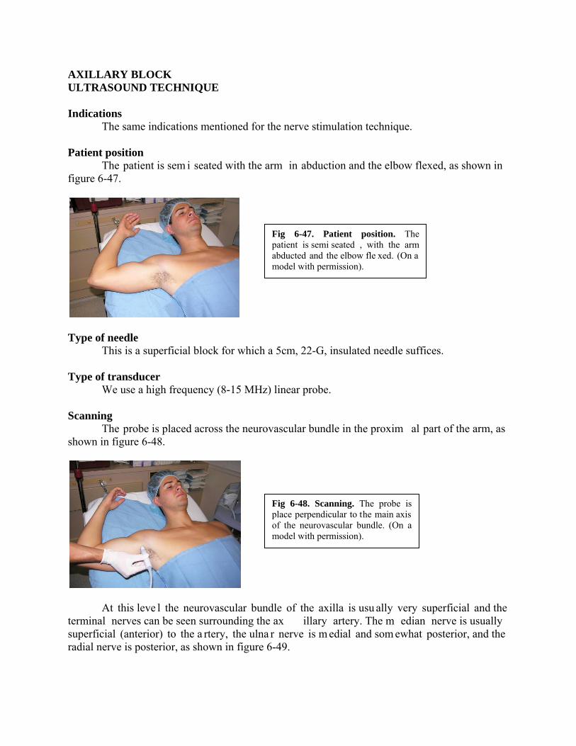
AXILLARY BLOCK ULTRASOUND TECHNIQUE Indications The same indications mentioned for the nerve stimulation technique. Patient position The patient is sem i seated with the arm in abduction and the elbow flexed, as shown in figure 6-47.
Type of needle This is a superficial block for which a 5cm, 22-G, insulated needle suffices. Type of transducer We use a high frequency (8-15 MHz) linear probe. Scanning The probe is placed across the neurovascular bundle in the proxim al part of the arm, as shown in figure 6-48.
At this leve l the neurovascular bundle of the axilla is usu ally very superficial and the terminal nerves can be seen surrounding the ax illary artery. The m edian nerve is usually superficial (anterior) to the a rtery, the ulna r nerve is m edial and som ewhat posterior, and the radial nerve is posterior, as shown in figure 6-49.
Fig 6-47. Patient position. The patient is semi seated , with the arm abducted and the elbow fle xed. (On a model with permission).
Fig 6-48. Scanning. The probe is place perpendicular to the main axis of the neurovascular bundle. (On a model with permission).

Distally in the ax illa the rad ial nerve starts shifting more lateral, but it still r emains posterior to the artery. The m usculocutaneous is lateral to the ar tery at all tim es and it can b e traced from its origin in the la teral cord proximally to its loc ation between biceps and coracobrachialis distally. If a single injection is planned it should be made in the proximity of the radial nerve. Individual injections of terminal nerves can be done as needed. An i mage of the neurovascular bundle of the axilla in cross section is shown in figure 6-50.
Needle insertion The needle is advanced in plane from lateral to medial, as shown in figure 6-51.
Fig 6-49. Terminal branches. The axillary sheath has been removed to show the relative location of the nerves with respect to the axillary artery. MACN: medial antebrachial cutaneous nerve; axi: axillary nerve. Cadaver dissection by Dr Franco. Image is copyrighted.
Fig 6-50. Axillary scanning. With the probe across the axilla the axillary artery (AA) is seen su rrounded by three main nerves, median (M), Ulna r (U) and Radial (R). Als o seen is Musculocutaneous nerve (MC), axillary vein (AV) and some muscles. (Author’s archive).
Fig 6-51. Needle insertion. The needle is advanced in plane from lateral (superior) to medial (inferior) and aimed toward the desired nerve. (On a model with permission).
We usually block first the m usculocutaneous nerve located in betw een biceps and coracobrachialis. To target this nerve the need le needs to be inserted at an angle of 30-45 degrees. Then the rest of the terminal branches are targeted as needed. These branches are m ore superficial so they need a much smaller angle of insertion, which facilitates needle visualization. Local anesthetic and volume
Because the nerves can be targeted individually it is possible to inject about 5 mL of local anesthetic solution around the desired nerve(s), usually requiring a total volum e of 20-30 m L. For anesthesia we u se 1.5% mepivacaine plus 1:400,000 epinephrine, which gives 3-4 hours of surgical anesthesia. For more prolonged anesthesia 0.5% ropiv acaine or bupiv acaine with epinephrine can be used. For postoperative analgesia we recommend 0.2% ropivacaine. Side effects and complications The most common complication at the axillary lev el is hematoma at the site , but ultrasound usually provides a good visualization of vessels and nerves at this location possibly decreasing the risk for inadvertent vascular punctures.
References
1. Brown DL. Brachial plexus anesthesia: an analysis of options. Yale J Biol Med 1993; 66: 415-431
2. Winnie AP. Interscalene brachial plexus block. Anesth Analg 1970; 49: 455-466 3. Kulenkampff D, Persky MA. Brachial plexus anesthesia. Ann Surg 1928; 87: 883-891 4. Winnie AP, Collins VJ. The subclavian perivascula r technique of brachial ple xus
anesthesia. Anesthesiology 1964; 25: 353-363 5. Franco CD, Vieira Z. 1,001 subclavian perivasc ular brachial plexus blocks: success with
a nerve stimulator. Reg Anesth Pain Med 2000; 25: 41-46 6. Franco CD. The subclavian perivascular block. Tech Reg Anesth Pain Med 1999; 3: 212-
216 7. De Andres J, Sala-Blan ch X. Perip heral nerve stimulation in the p ractice of brachial
plexus anesthesia: a review. Reg Anesth Pain Med 2001; 26: 478-483 8. Greenblatt Gm, Denson GS. Need le nerve stimu lator-locator: nerve blocks with a new
instrument for locating nerves. Anesth Analg 1962; 41: 599-602 9. Hadzic A, Vloka J, Hadzic N, et al. Nerve stimulators used for peripheral nerve blocks
vary in their electrical characteristics. Anesthesiology 2003; 98: 969-974 10. Passannante AN. Spinal anesthes ia and perm anent neurologic deficit after interscalene
block. Anesth Analg 1996; 82: 873-874 11. Urmey WF, Grossi P, Sharrock N E, Stanton J, Gloeggler PJ. Digi tal pressure during
interscalene block is clin ically ineffective in preventing anesthetic spread to the cervical plexus. Anesth Analg 1996; 83: 366-370
12. Silverstein WB, Saiyed M, Brown AR. Inte rscalene block with a nerve stim ulator: A deltoid motor response is a satisfactory endpoi nt for successful block. Reg Anesth pain Med 2000; 25: 356-359
13. Urmey WF, Talts KH, Sharrock NE. One hundred percent incidence of hemidiaphragmatic paresis asso ciated with intersca lene brachial plexus anesthesia as diagnosed by ultrasonography. Anesth Analg 1991; 72: 498-503
14. Urmey WF. Interscalene block: The truth abou t twitches (editorial ). Reg Anesth pain Med 2000; 25: 340-342
15. Brand L, Papper EM. A com parison of supr aclavicular and axillary techniques for brachial plexus blocks. Anesthesiology 1961; 22: 226-229
16. Brown DL. Atlas of regional anesthesia. Philadelphia, PA: W.B. Saunders, 1992 17. Mulroy MF. Regional anesth esia: An illu strated procedural guide. 3 rd edition.
Philadelphia, PA; Lippincott Williams & Wilkins 2002 18. Urmey WF, Stanton J. Inability to consiste ntly elicit a motor response following sensory
paresthesia during interscalene block administration. Anesthesiology 2002; 96: 552-554 19. Neal JM, Moore JM, Kopacz DJ, Liu SS, Kramer DJ, Plo rde JJ. Quantitative analysis of
respiratory, motor, and sensory function afte r supraclavicular block. Anesth Analg 1998; 86: 1239-1244
20. Franco CD, Domashevich V, Voronov G, Rafizad A, Jelev T. The s upraclavicular block with a nerve stimulator: To decrease or not to decrease, that is the question. Anesth Analg 2004; 98: 1167-1171
21. Franco CD, Gloss FJ, Voronov G, Tyler SG, Stojiljkovic LS. Supraclavicular block in the obese population: An analysis of 2020 blocks. Anesth Analg 2006; 102: 1252-1254

22. Perlas A, Chan V: Ultrasound-assisted nerve blocks. In: Textbook of Regional Anesthesia, Hadzic A (ed). New York, McGraw Hill, 2007, pp 663-672
23. Franco CD, et al. Gross anatom y of the brach ial plexus sheath in human cadavers. Reg Anesth Pain Med 2008; 33: 64-69
24. Neal JM, Gerancher JC, Hebl JR, Ilfeld BM, McCartney CJL, Franco CD, Hogan QH. Upper Extremity Regional Anesth esia: Essentials of Our Current Understanding. Reg Anesth Pain Med 2009; 34: 134-170