Embed Size (px)
Citation preview
ARM Exceptions Hsung-Pin ChangDepartment of Computer ScienceNational Chung Hsing University

Outlineo ARM Exceptionso Entering and Leaving an Exceptiono Installing an Exception Handlero SWI Handlerso Interrupt Handlerso Reset Handlerso Undefined Instruction Handlerso Prefetch Abort Handlero Data Abort Handler

ARM Exceptionso ARM Exception Types
o ARM Exception Vector Table
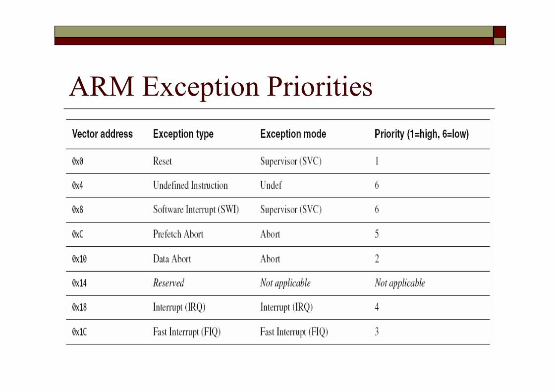
o ARM Exception Priorities
o Use of Modes and Registers by Exceptions

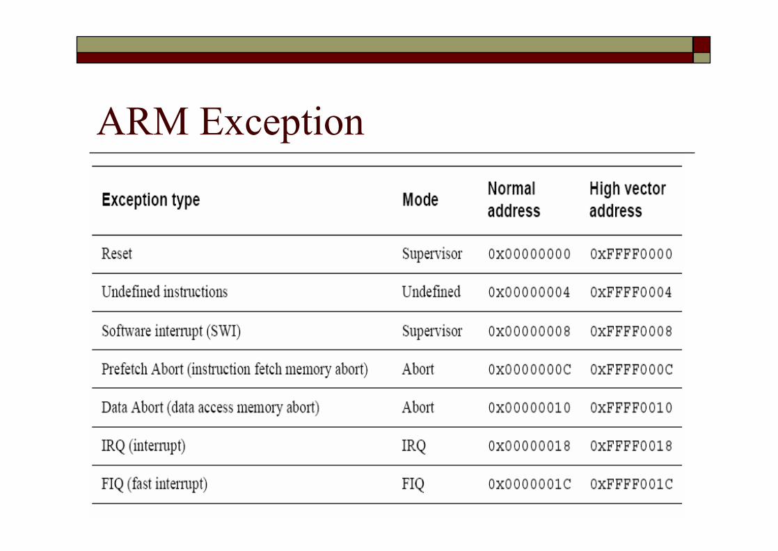
ARM Exception Typeso Reseto Undefined instructiono Software Interrupt (SWI)o Prefetch Aborto Data Aborto IRQo FIQ
ARM Exceptions Types (Cont.)o Reset
n Occurs when the processor reset pin is assertedo For signaling Power-upo For resetting as if the processor has just powered up
n Software reseto Can be done by branching to the reset vector (0x0000)
o Undefined instructionn Occurs when the processor or coprocessors cannot
recognize the currently execution instruction

ARM Exceptions Types (Cont.)o Software Interrupt (SWI)
n User-defined interrupt instructionn Allow a program running in User mode to request
privileged operations that are in Supervisor modeo For example, RTOS functions
o Prefetch Abortn Fetch an instruction from an illegal address, the
instruction is flagged as invalidn However, instructions already in the pipeline continue to
execute until the invalid instruction is reached and then a Prefetch Abort is generated.
ARM Exceptions Types (Cont.)o Data Abort
n A data transfer instruction attempts to load or store data at an illegal address
o IRQn The processor external interrupt request pin is asserted
(LOW) and the I bit in the CPSR is clear (enable)o FIQ
n The processor external fast interrupt request pin is asserted (LOW) and the F bit in the CPSR is clear (enable)
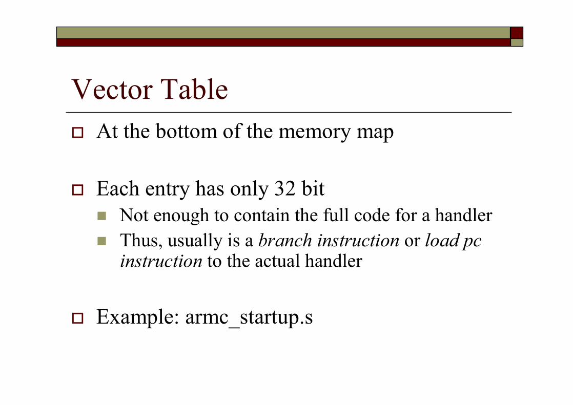
Vector Tableo At the bottom of the memory map
o Each entry has only 32 bitn Not enough to contain the full code for a handlern Thus, usually is a branch instruction or load pc
instruction to the actual handler
o Example: armc_startup.s
ARM Exception
ARM Exception Vector Table
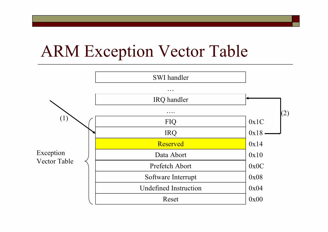
ResetUndefined Instruction
Software InterruptPrefetch Abort
Data AbortReserved
IRQFIQ
0x000x040x080x0C0x100x140x180x1C
Exception Vector Table
….IRQ handler…
SWI handler
(1)(2)

ARM Exception Events
ARM Exception Priorities
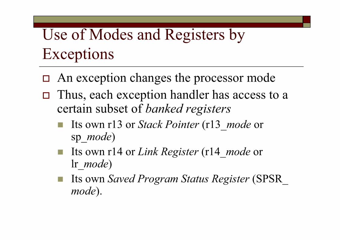
Use of Modes and Registers by Exceptionso An exception changes the processor modeo Thus, each exception handler has access to a
certain subset of banked registersn Its own r13 or Stack Pointer (r13_mode or
sp_mode)n Its own r14 or Link Register (r14_mode or
lr_mode)n Its own Saved Program Status Register (SPSR_
mode).

Register Organization in ARM States
Entering and Leaving an Exceptiono The Process Response to an Exception
o Returning from an Exception Handler
o The Return Address and Return Instruction

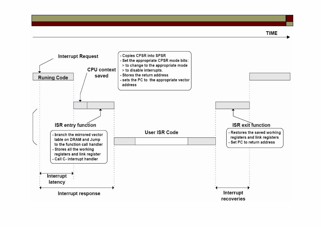
The Process Response to an Exceptiono Copies the CPSR into the SPSR for the mode in which the
exception is to be handled.n Saves the current mode, interrupt mask, and condition flags.
o Changes the appropriate CPSR mode bitsn Change to the appropriate mode
o Map in the appropriate banked registers for that modeo Disable interrupts
n IRQs are disabled when any exception occurs.n FIQs are disabled when a FIQ occurs, and on reset
o Set lr_mode to the return addressn Discuss in the next few slides
o Set the program counter to the vector address for the exception

The Process Response to an Exception (Cont.)o For example, when reset, ARMn Overwrites R14_svc and SPSR_svc by copying
the current values of the PC and CPSR into themn Forces M[4:0] to 10011 (Supervisor mode), sets
the I and F bits in the CPSR, and clears the CPSR's T bit
n Forces the PC to fetch the next instruction from address 0x00.
n Execution resumes in ARM state.
The Process Response to an Exception (Cont.)
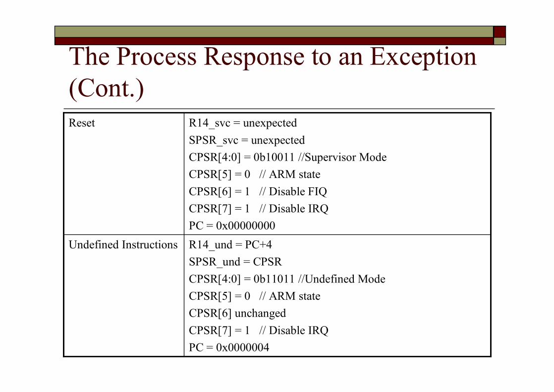
R14_und = PC+4 SPSR_und = CPSRCPSR[4:0] = 0b11011 //Undefined ModeCPSR[5] = 0 // ARM stateCPSR[6] unchangedCPSR[7] = 1 // Disable IRQPC = 0x0000004
Undefined Instructions
R14_svc = unexpected SPSR_svc = unexpectedCPSR[4:0] = 0b10011 //Supervisor ModeCPSR[5] = 0 // ARM stateCPSR[6] = 1 // Disable FIQCPSR[7] = 1 // Disable IRQPC = 0x00000000
Reset
The Process Response to an Exception (Cont.)
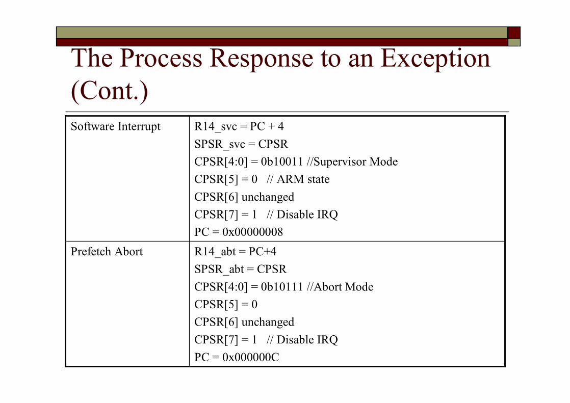
R14_abt = PC+4 SPSR_abt = CPSRCPSR[4:0] = 0b10111 //Abort ModeCPSR[5] = 0CPSR[6] unchangedCPSR[7] = 1 // Disable IRQPC = 0x000000C
Prefetch Abort
R14_svc = PC + 4SPSR_svc = CPSRCPSR[4:0] = 0b10011 //Supervisor ModeCPSR[5] = 0 // ARM stateCPSR[6] unchangedCPSR[7] = 1 // Disable IRQPC = 0x00000008
Software Interrupt

The Process Response to an Exception (Cont.)
R14_abt = PC+4 SPSR_abt = CPSRCPSR[4:0] = 0b10010 //Abort ModeCPSR[5] = 0CPSR[6] unchangedCPSR[7] = 1 // Disable IRQPC = 0x0000018
Interrupt Request
R14_abt = PC + 8SPSR_abt = CPSRCPSR[4:0] = 0b10111 //Abort ModeCPSR[5] = 0 // ARM stateCPSR[6] unchangedCPSR[7] = 1 // Disable IRQPC = 0x00000010
Data Abort
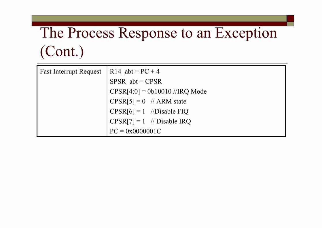
The Process Response to an Exception (Cont.)
R14_abt = PC + 4SPSR_abt = CPSRCPSR[4:0] = 0b10010 //IRQ ModeCPSR[5] = 0 // ARM stateCPSR[6] = 1 //Disable FIQCPSR[7] = 1 // Disable IRQPC = 0x0000001C
Fast Interrupt Request

Returning From an Exception Handlero Returning from an exception handlern Depend on whether the exception handler uses
the stack operations or not
o Generally, to return execution to the original execution placen Restore the CPSR from spsr_moden Restore the program counter using the return
address stored in lr_mode

Returning From an Exception Handler : Simple Returno If not require the destination mode registers
to be restored from the stackn Above two operations can be carried out by a
data processing instruction witho The S flag (bit 20) set
n Update the CPSR flags when executing the data processing instruction
n SUBS, MOVSo The program counter as the destination register
n Example: MOVS pc, lr //pc = lr
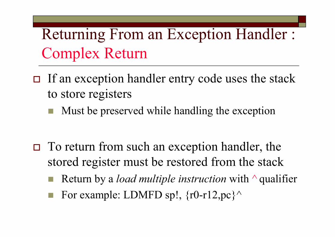
Returning From an Exception Handler : Complex Returno If an exception handler entry code uses the stack
to store registers n Must be preserved while handling the exception
o To return from such an exception handler, the stored register must be restored from the stackn Return by a load multiple instruction with ^ qualifiern For example: LDMFD sp!, {r0-r12,pc}^
Returning From an Exception Handlero Note, do not need to return from the reset
handlern The reset handler executes your main code directly
o The actual location when an exception is taken depends on the exception typen The return address may not necessarily be the next
instruction pointed to by the pc
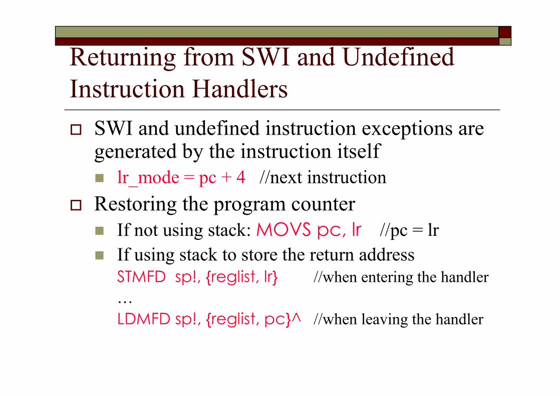
Returning from SWI and Undefined Instruction Handlerso SWI and undefined instruction exceptions are
generated by the instruction itselfn lr_mode = pc + 4 //next instruction
o Restoring the program countern If not using stack: MOVS pc, lr //pc = lrn If using stack to store the return address
STMFD sp!, {reglist, lr} //when entering the handler…LDMFD sp!, {reglist, pc}^ //when leaving the handler

Returning from FIQ and IRQo FIQ and IRQ are generated only after the
execution of an instructionn The program counter has been updated
n lr_mode = PC + 4o Point to one instruction beyond the end of the
instruction in which the exception occurred
PCFIQ or IRQ occurs
PC+4
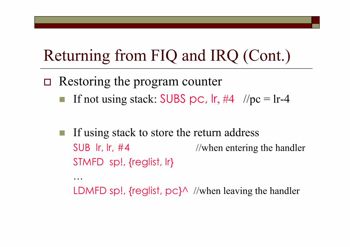
Returning from FIQ and IRQ (Cont.)o Restoring the program countern If not using stack: SUBS pc, lr, #4 //pc = lr-4
n If using stack to store the return addressSUB lr, lr, #4 //when entering the handlerSTMFD sp!, {reglist, lr}…LDMFD sp!, {reglist, pc}^ //when leaving the handler
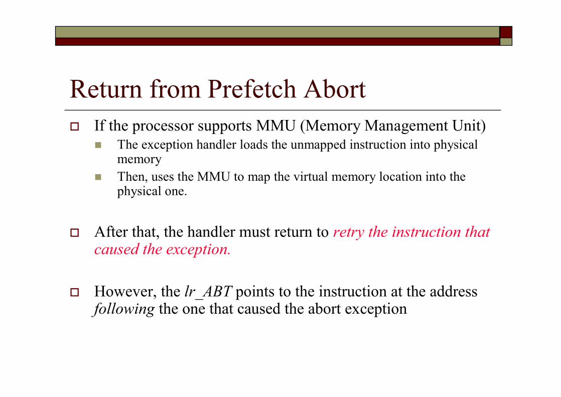
Return from Prefetch Abort o If the processor supports MMU (Memory Management Unit)
n The exception handler loads the unmapped instruction into physical memory
n Then, uses the MMU to map the virtual memory location into the physical one.
o After that, the handler must return to retry the instruction that caused the exception.
o However, the lr_ABT points to the instruction at the address following the one that caused the abort exception
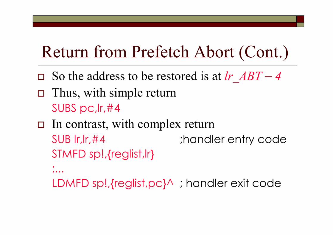
Return from Prefetch Abort (Cont.)o So the address to be restored is at lr_ABT – 4o Thus, with simple return
SUBS pc,lr,#4o In contrast, with complex return
SUB lr,lr,#4 ;handler entry codeSTMFD sp!,{reglist,lr};...LDMFD sp!,{reglist,pc}^ ; handler exit code
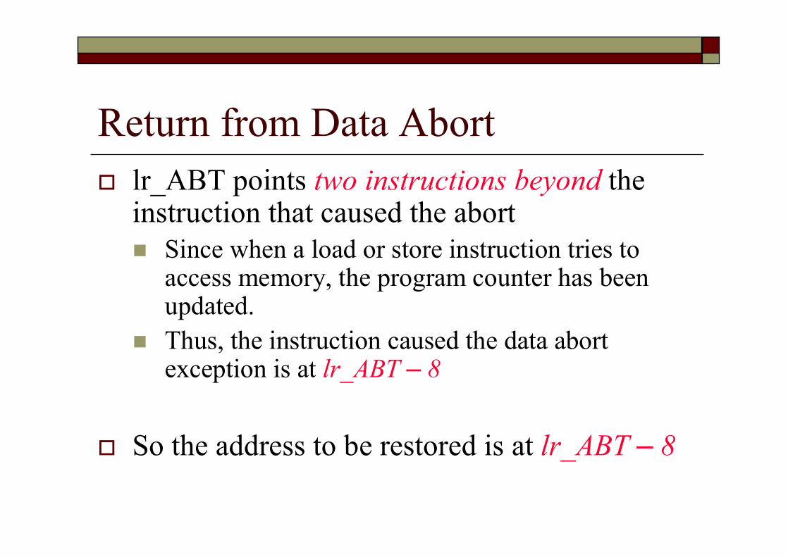
Return from Data Aborto lr_ABT points two instructions beyond the
instruction that caused the abortn Since when a load or store instruction tries to
access memory, the program counter has been updated.
n Thus, the instruction caused the data abort exception is at lr_ABT – 8
o So the address to be restored is at lr_ABT – 8
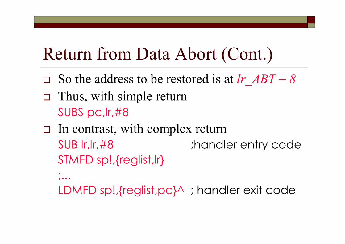
Return from Data Abort (Cont.)o So the address to be restored is at lr_ABT – 8o Thus, with simple return
SUBS pc,lr,#8o In contrast, with complex return
SUB lr,lr,#8 ;handler entry codeSTMFD sp!,{reglist,lr};...LDMFD sp!,{reglist,pc}^ ; handler exit code
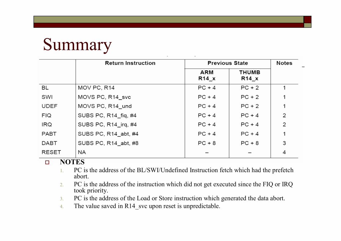
Summary
o NOTES1. PC is the address of the BL/SWI/Undefined Instruction fetch which had the prefetch
abort.2. PC is the address of the instruction which did not get executed since the FIQ or IRQ
took priority.3. PC is the address of the Load or Store instruction which generated the data abort.4. The value saved in R14_svc upon reset is unpredictable.

Install an Exception Handlero Any new exception handler must be installed in the
vector table
o Exception handlers can be installed in two waysn Branch instruction: simple but have one limitation
o Branch instruction only has a range of 32 MB relative to the pc
n Load pc instruction: set pc byo Load instruction to load the handler address into the program
counter
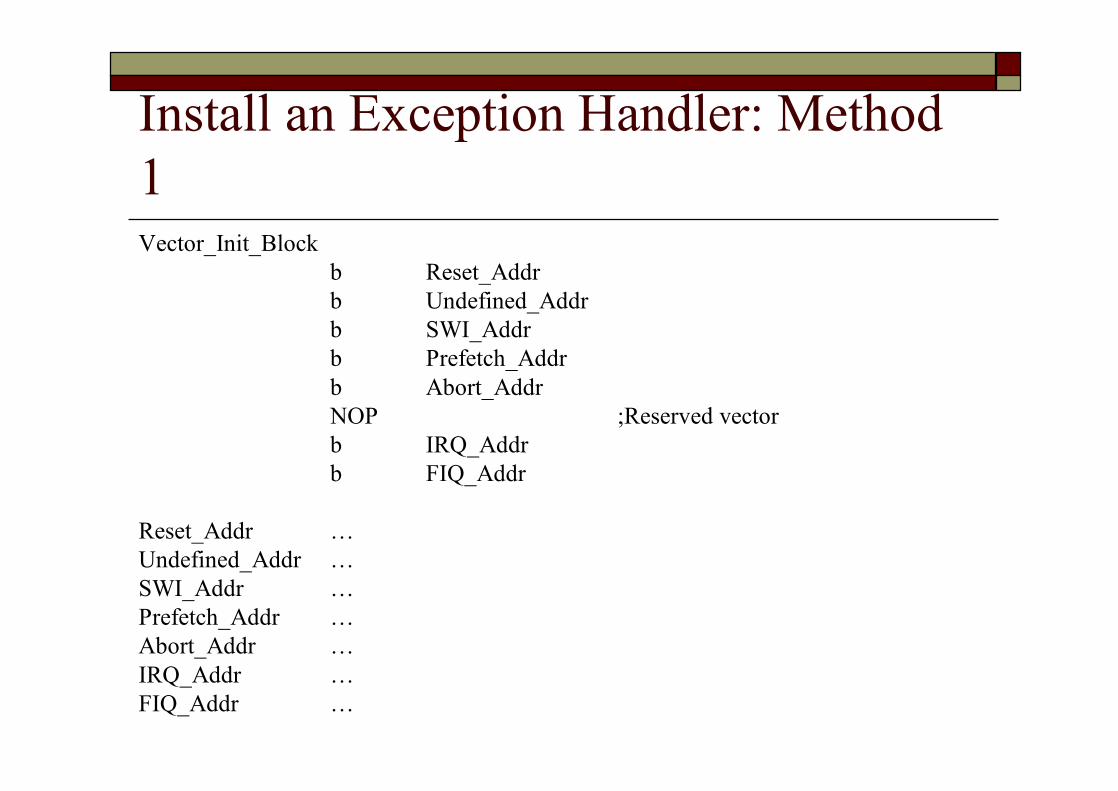
Install an Exception Handler: Method 1Vector_Init_Block
b Reset_Addrb Undefined_Addrb SWI_Addrb Prefetch_Addrb Abort_AddrNOP ;Reserved vectorb IRQ_Addrb FIQ_Addr
Reset_Addr …Undefined_Addr …SWI_Addr …Prefetch_Addr …Abort_Addr …IRQ_Addr …FIQ_Addr …

Install an Exception Handler: Method 2
Vector_Init_BlockLDR PC, Reset_AddrLDR PC, Undefined_AddrLDR PC, SWI_AddrLDR PC, Prefetch_AddrLDR PC, Abort_AddrNOP ;Reserved vectorLDR PC, IRQ_AddrLDR PC, FIQ_Addr
Reset_Addr DCD Start_BootUndefined_Addr DCD Undefined_HandlerSWI_Addr DCD SWI_HandlerPrefetch_Addr DCD Prefetch_HandlerAbort_Addr DCD Abort_Handler
DCD 0 ;Reserved vectorIRQ_Addr DCD IRQ_HandlerFIQ_Addr DCD FIQ_Handler
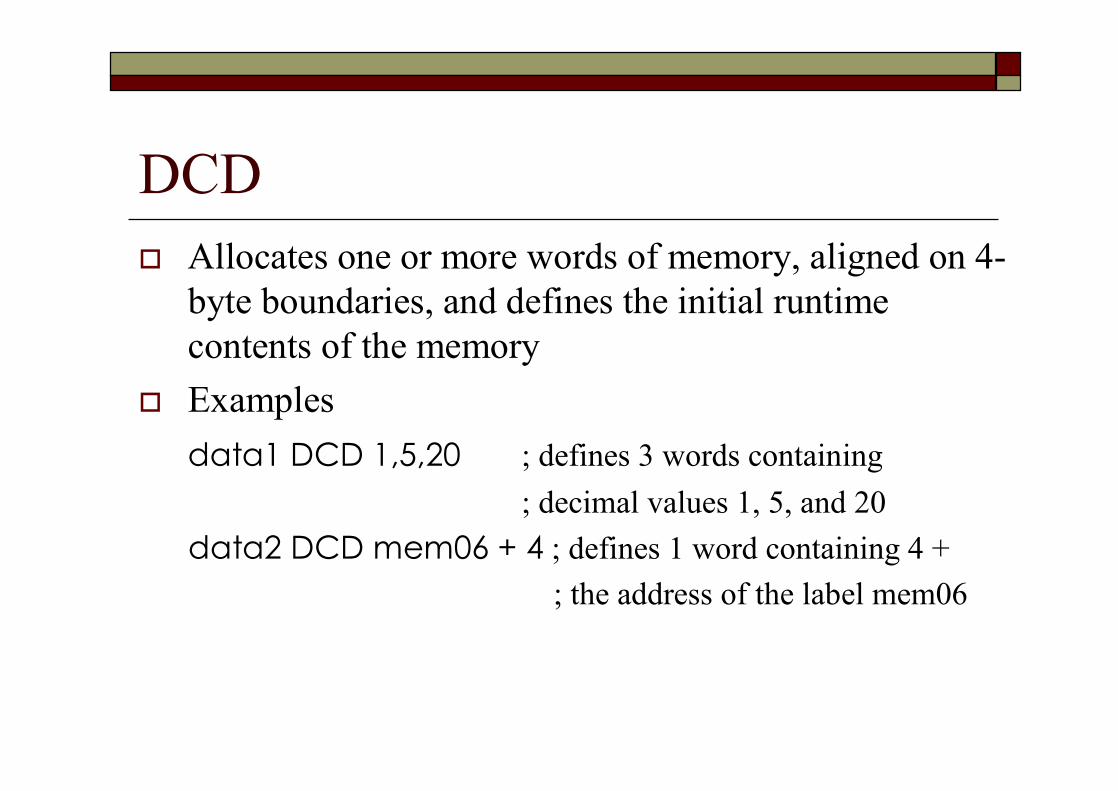
DCDo Allocates one or more words of memory, aligned on 4-
byte boundaries, and defines the initial runtime contents of the memory
o Examplesdata1 DCD 1,5,20 ; defines 3 words containing
; decimal values 1, 5, and 20data2 DCD mem06 + 4 ; defines 1 word containing 4 +
; the address of the label mem06
SWI Handlerso Top-Level SWI Handlerso SWI Routine in Assembly Languageo SWI Routine in Co How to Pass Values in and out of a SWI
Routineo Calling SWIs from an Application
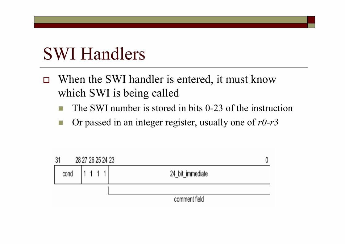
SWI Handlerso When the SWI handler is entered, it must know
which SWI is being calledn The SWI number is stored in bits 0-23 of the instructionn Or passed in an integer register, usually one of r0-r3

Top-Level SWI Handlerso Because SVC only has its own LR_svc and SP_svc
n Save all other r0~r12 to the stacko To calculate the SWI number
n Calculate the instruction address causing the SWIo Since lr_SVC holds the address of the instruction that follows the
SWI instruction, thuso LDR r0, [lr, #-4] ; derive the SWI instruction’s address
n The SWI number is extracted by clearing the top eight bits of the opcode:o BIC r0, r0, #0xFF000000
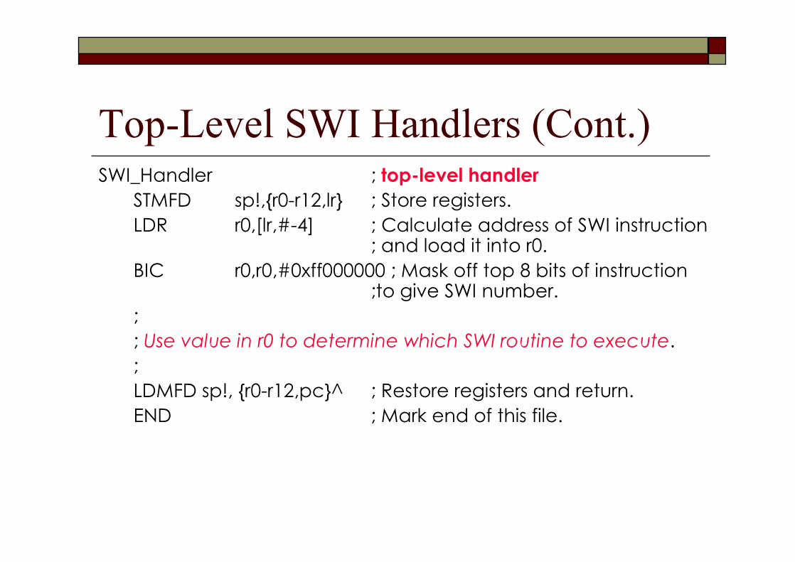
Top-Level SWI Handlers (Cont.)SWI_Handler ; top-level handler
STMFD sp!,{r0-r12,lr} ; Store registers.LDR r0,[lr,#-4] ; Calculate address of SWI instruction
; and load it into r0.BIC r0,r0,#0xff000000 ; Mask off top 8 bits of instruction
;to give SWI number.;; Use value in r0 to determine which SWI routine to execute.;LDMFD sp!, {r0-r12,pc}^ ; Restore registers and return.END ; Mark end of this file.

Top-Level SWI Handlers (Cont.)o Above program is called top-level handlern Must always be written in ARM assembly
language
o However, the routines to handle each SWI can be written in either assembly language or in C
SWI Routine in Assembly Languageo If the routines to handle each SWI in written
in Assembly Languagen The easiest way is using a jump table
o In the top-level handler, the r0 contains the SWI number
o Thus, the following code can be inserted into the top-level handler, i.e., SWI_Handlern Following on from the BIC instruction
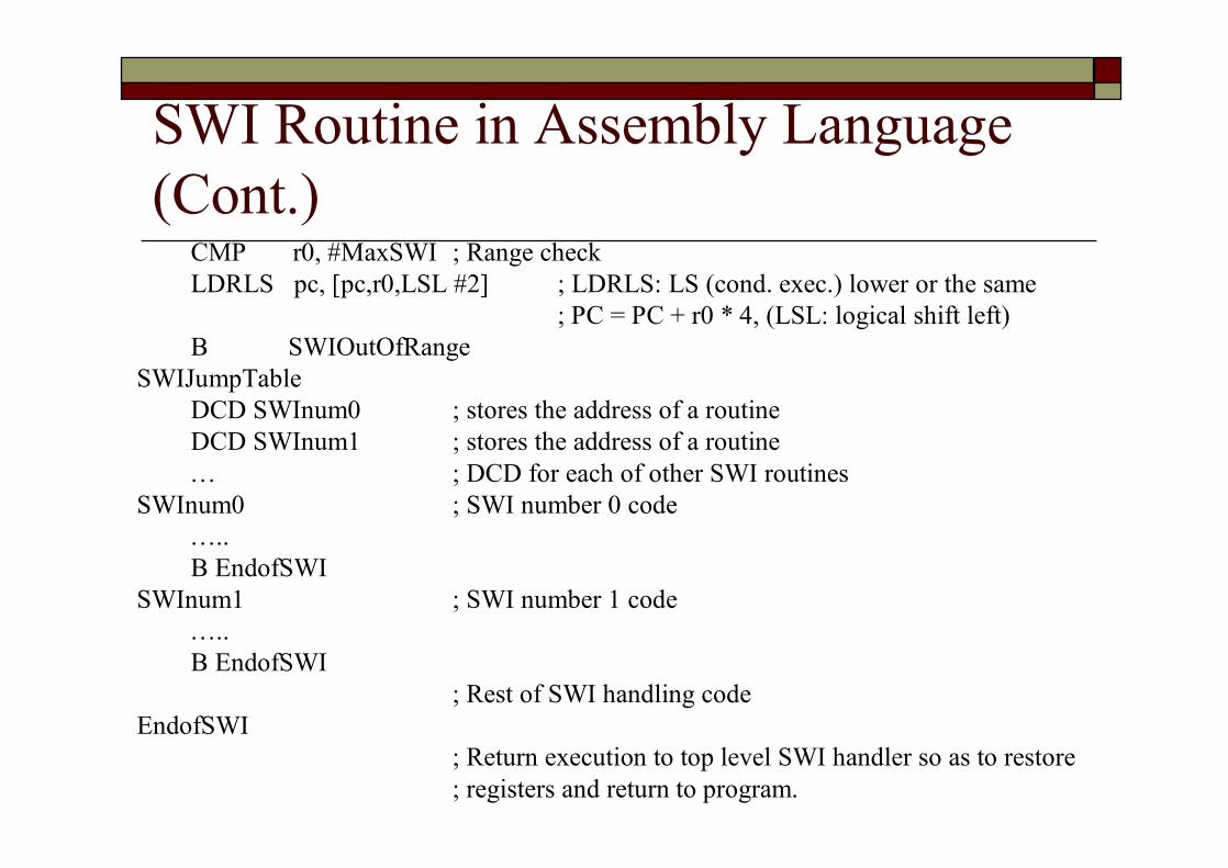
SWI Routine in Assembly Language (Cont.)
CMP r0, #MaxSWI ; Range checkLDRLS pc, [pc,r0,LSL #2] ; LDRLS: LS (cond. exec.) lower or the same
; PC = PC + r0 * 4, (LSL: logical shift left)B SWIOutOfRange
SWIJumpTableDCD SWInum0 ; stores the address of a routineDCD SWInum1 ; stores the address of a routine… ; DCD for each of other SWI routines
SWInum0 ; SWI number 0 code…..B EndofSWI
SWInum1 ; SWI number 1 code…..B EndofSWI
; Rest of SWI handling codeEndofSWI
; Return execution to top level SWI handler so as to restore; registers and return to program.
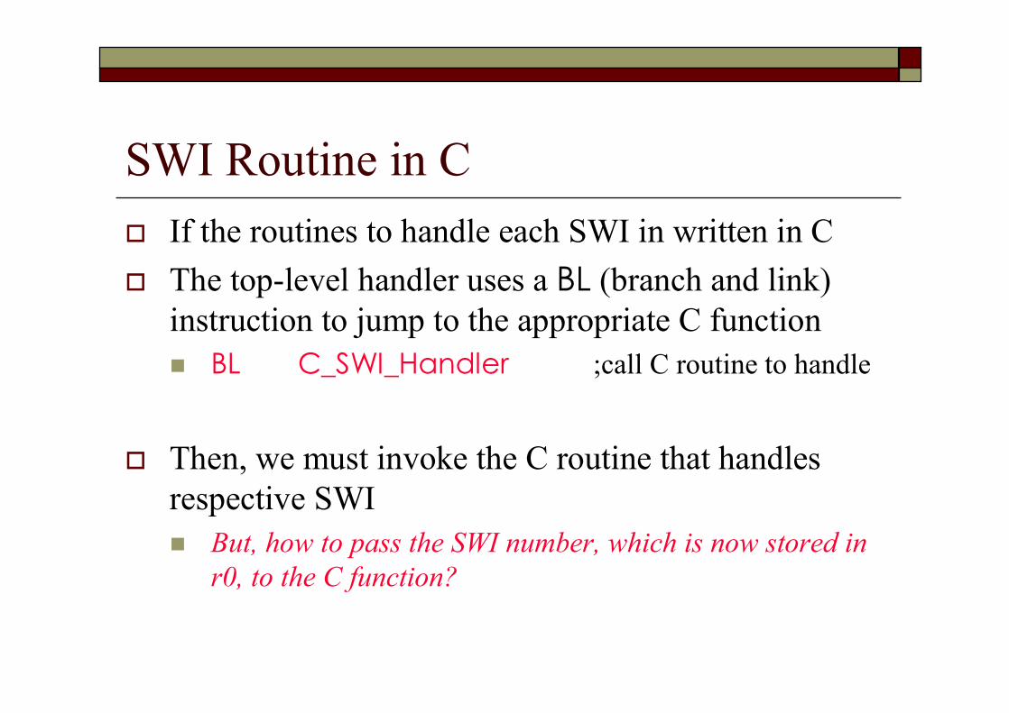
SWI Routine in Co If the routines to handle each SWI in written in Co The top-level handler uses a BL (branch and link)
instruction to jump to the appropriate C functionn BL C_SWI_Handler ;call C routine to handle
o Then, we must invoke the C routine that handles respective SWIn But, how to pass the SWI number, which is now stored in
r0, to the C function?
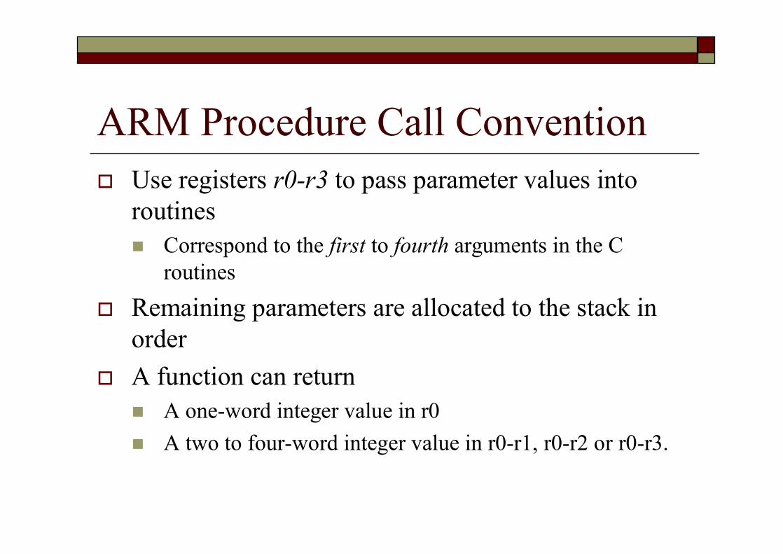
ARM Procedure Call Conventiono Use registers r0-r3 to pass parameter values into
routinesn Correspond to the first to fourth arguments in the C
routineso Remaining parameters are allocated to the stack in
ordero A function can return
n A one-word integer value in r0n A two to four-word integer value in r0-r1, r0-r2 or r0-r3.
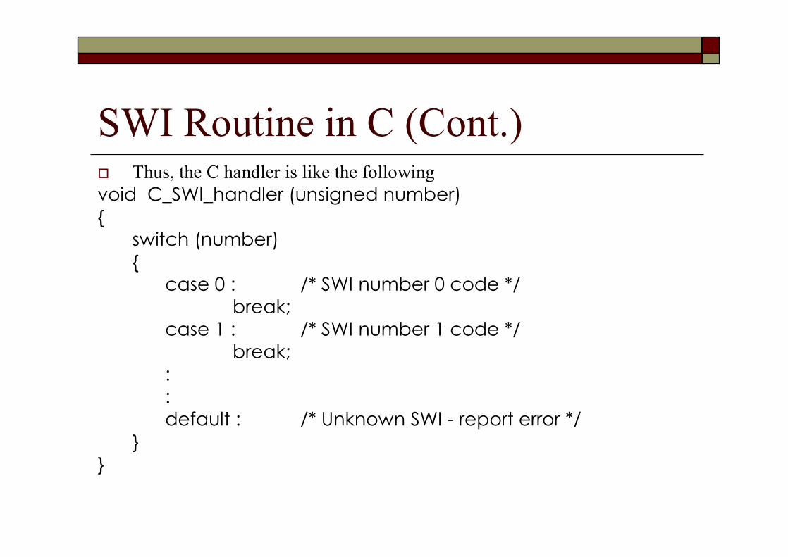
SWI Routine in C (Cont.)o Thus, the C handler is like the followingvoid C_SWI_handler (unsigned number) {
switch (number){
case 0 : /* SWI number 0 code */break;
case 1 : /* SWI number 1 code */break;
::default : /* Unknown SWI - report error */
}}
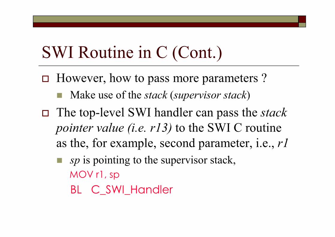
SWI Routine in C (Cont.)o However, how to pass more parameters ?n Make use of the stack (supervisor stack)
o The top-level SWI handler can pass the stack pointer value (i.e. r13) to the SWI C routine as the, for example, second parameter, i.e., r1n sp is pointing to the supervisor stack,
MOV r1, spBL C_SWI_Handler
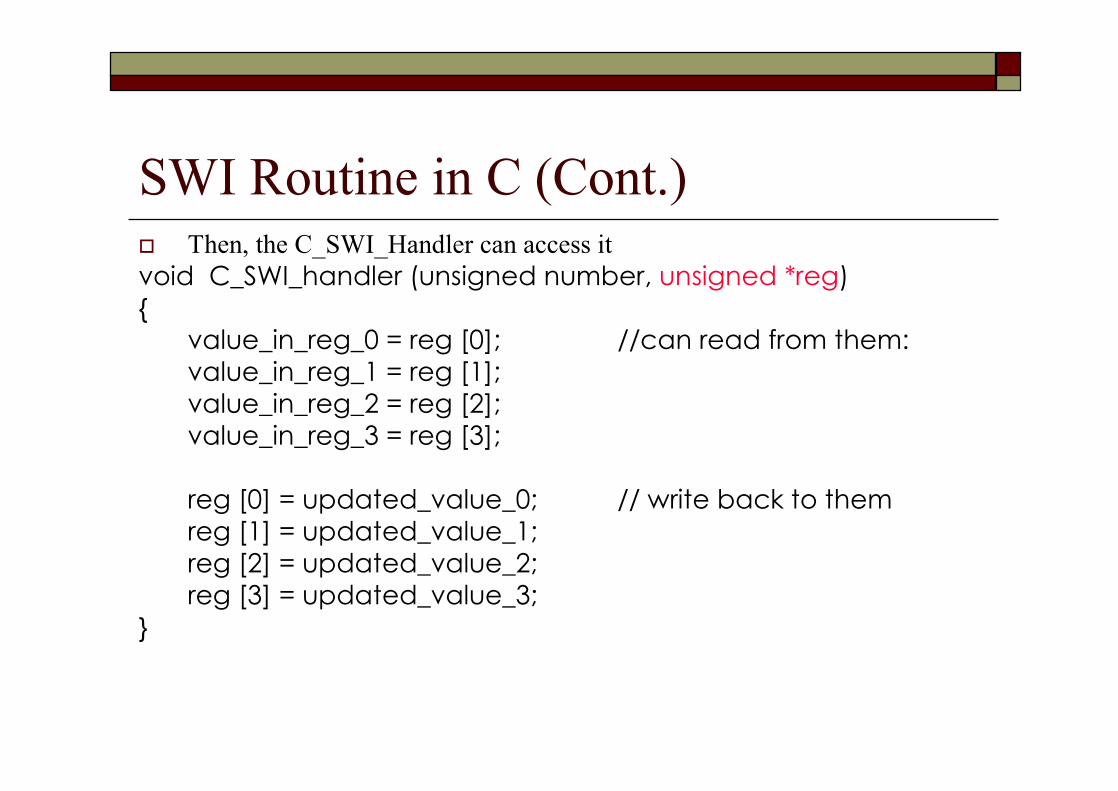
SWI Routine in C (Cont.)o Then, the C_SWI_Handler can access itvoid C_SWI_handler (unsigned number, unsigned *reg) {
value_in_reg_0 = reg [0]; //can read from them:value_in_reg_1 = reg [1];value_in_reg_2 = reg [2];value_in_reg_3 = reg [3];
reg [0] = updated_value_0; // write back to themreg [1] = updated_value_1;reg [2] = updated_value_2;reg [3] = updated_value_3;
}
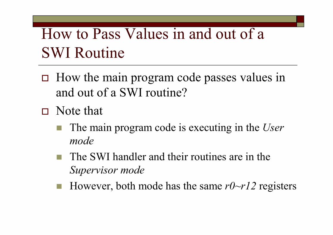
How to Pass Values in and out of a SWI Routineo How the main program code passes values in
and out of a SWI routine?o Note thatn The main program code is executing in the User
moden The SWI handler and their routines are in the
Supervisor mode n However, both mode has the same r0~r12 registers
How to Pass Values in and out of a SWI Routine (Cont.)o Thus, the application code and SWI routine
can communicate by r0~r12 registers
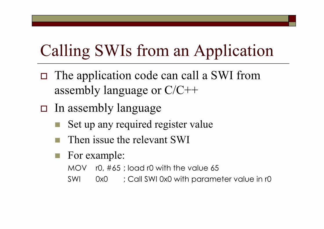
Calling SWIs from an Applicationo The application code can call a SWI from
assembly language or C/C++o In assembly languagen Set up any required register valuen Then issue the relevant SWI n For example:
MOV r0, #65 ; load r0 with the value 65SWI 0x0 ; Call SWI 0x0 with parameter value in r0
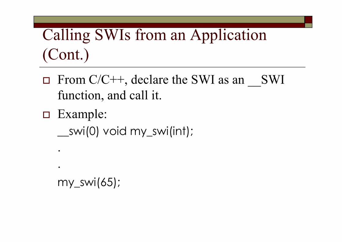
Calling SWIs from an Application (Cont.)o From C/C++, declare the SWI as an __SWI
function, and call it.o Example:
__swi(0) void my_swi(int);..my_swi(65);
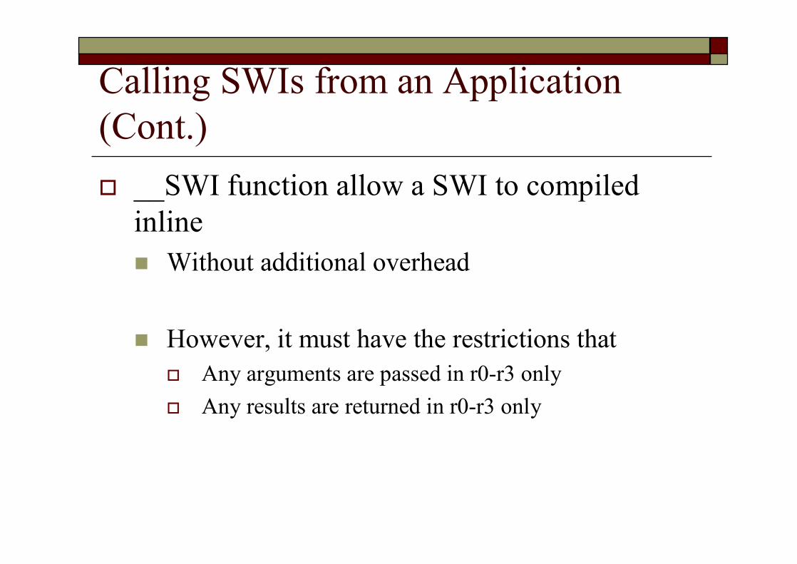
Calling SWIs from an Application (Cont.)o __SWI function allow a SWI to compiled
inlinen Without additional overhead
n However, it must have the restrictions thato Any arguments are passed in r0-r3 onlyo Any results are returned in r0-r3 only
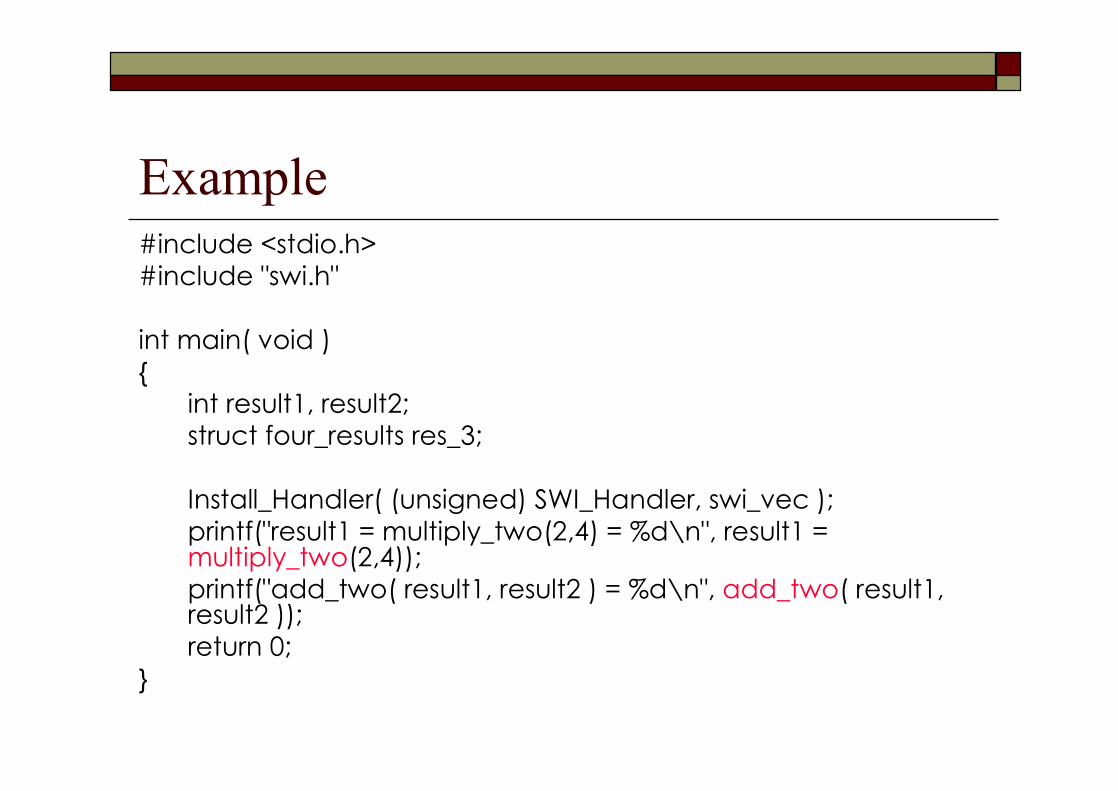
Example#include <stdio.h>#include "swi.h"
int main( void ){
int result1, result2;struct four_results res_3;
Install_Handler( (unsigned) SWI_Handler, swi_vec );printf("result1 = multiply_two(2,4) = %d\n", result1 = multiply_two(2,4));printf("add_two( result1, result2 ) = %d\n", add_two( result1, result2 ));return 0;
}

Calling SWIs from an Application (Cont.)o swi.h
__swi(0) int multiply_two(int, int);__swi(1) int add_two(int, int);
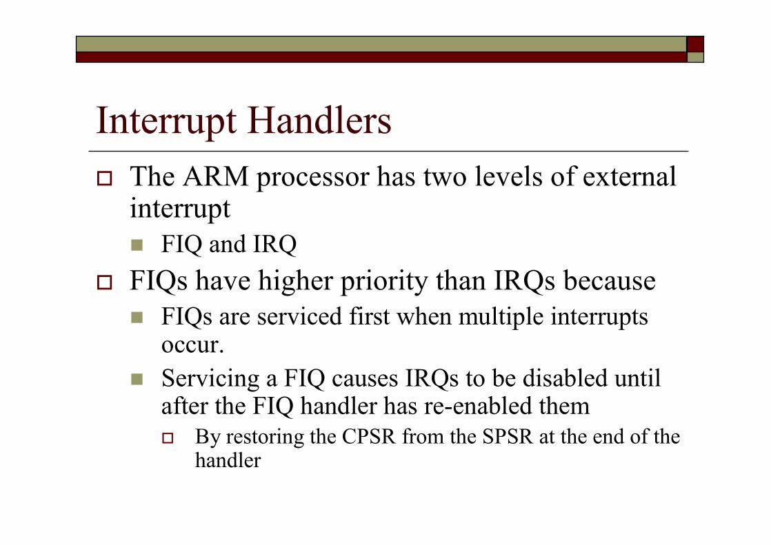
Interrupt Handlerso The ARM processor has two levels of external
interruptn FIQ and IRQ
o FIQs have higher priority than IRQs becausen FIQs are serviced first when multiple interrupts
occur.n Servicing a FIQ causes IRQs to be disabled until
after the FIQ handler has re-enabled themo By restoring the CPSR from the SPSR at the end of the
handler
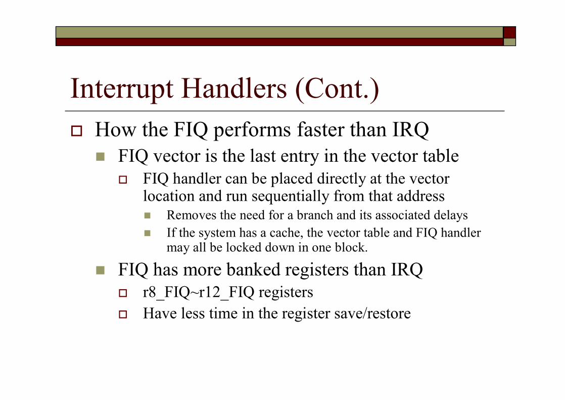
Interrupt Handlers (Cont.)o How the FIQ performs faster than IRQn FIQ vector is the last entry in the vector table
o FIQ handler can be placed directly at the vector location and run sequentially from that addressn Removes the need for a branch and its associated delaysn If the system has a cache, the vector table and FIQ handler
may all be locked down in one block.
n FIQ has more banked registers than IRQo r8_FIQ~r12_FIQ registerso Have less time in the register save/restore

IRQ HandlerIRQ_Handler: ; top-level handler
STMFD sp!,{r0-r12,lr} ; Store registers.BL ISR_IRQ
LDMFD sp!, {r0-r12,pc} ; Restore registers and returnSUBS pc, lr, #4END ; Mark end of this file.
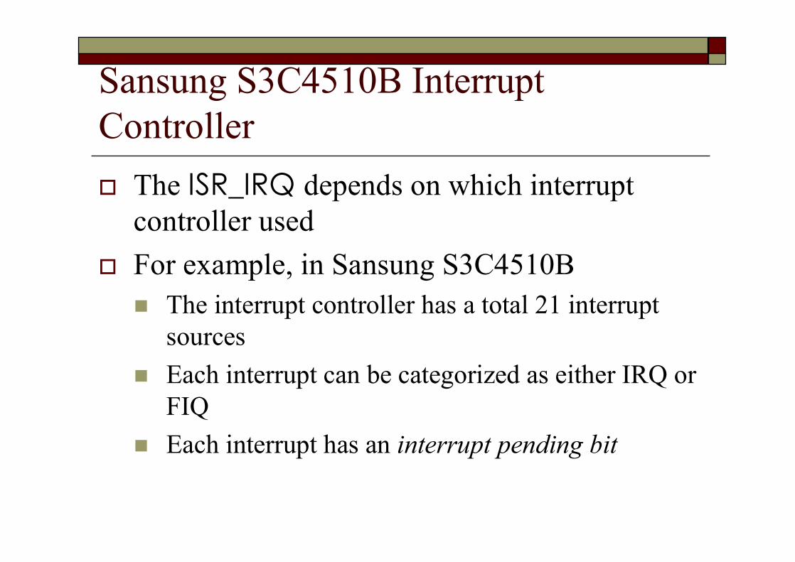
Sansung S3C4510B Interrupt Controllero The ISR_IRQ depends on which interrupt
controller usedo For example, in Sansung S3C4510Bn The interrupt controller has a total 21 interrupt
sourcesn Each interrupt can be categorized as either IRQ or
FIQn Each interrupt has an interrupt pending bit
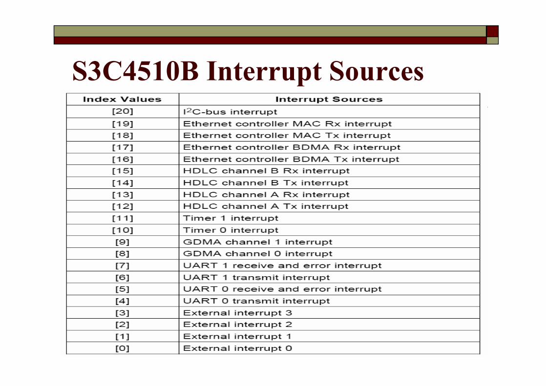
S3C4510B Interrupt Sources

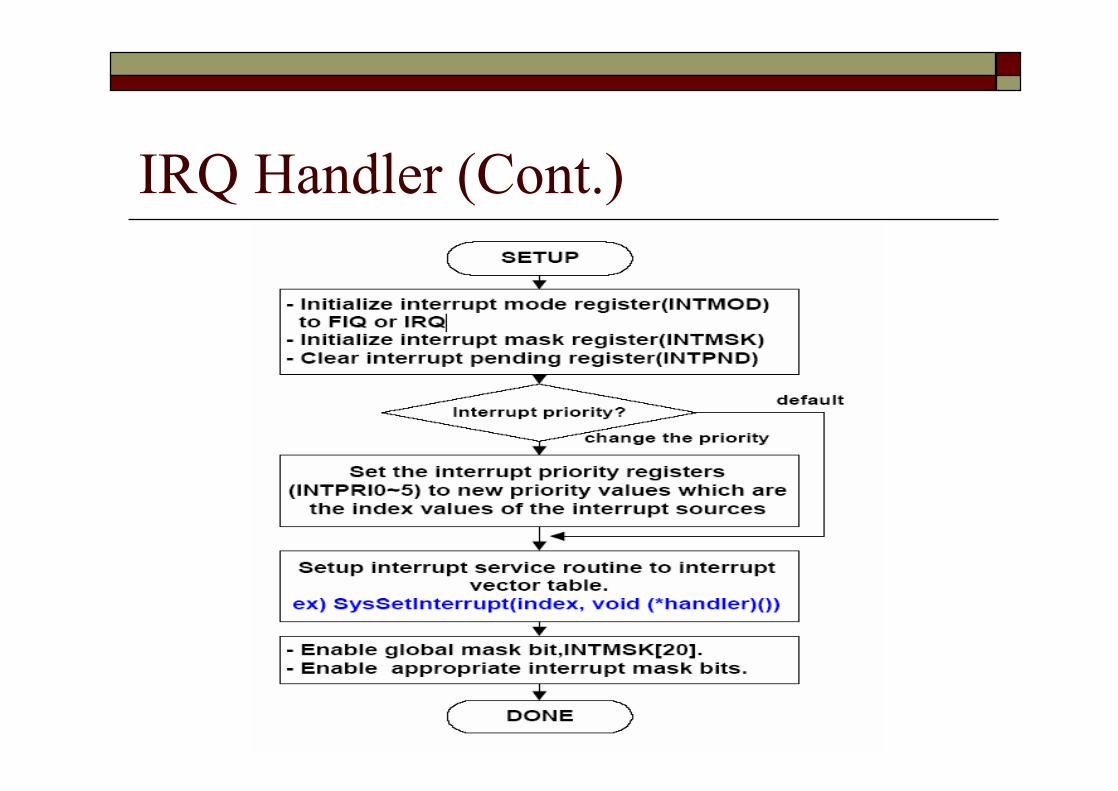
Sansung S3C4510B Interrupt Controller (Cont.)o Five special registers used to control the interrupt generation
and handlingn Interrupt mode register
o Defines the interrupt mode, IRQ or FIQ, for each interrupt source.n Interrupt pending register
o Indicates that an interrupt request is pendingn Interrupt mask register
o The current interrupt is disabled if the corresponding mask bit is "1“o If the global mask bit (bit 21) is set to "1", no interrupts are serviced.
n Interrupt priority registerso Determine the interrupt priority
n Interrupt offset registero Determine the highest priority among the pending interrupts.
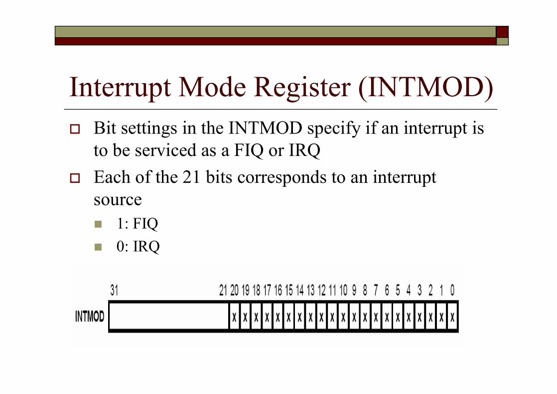
Interrupt Mode Register (INTMOD)o Bit settings in the INTMOD specify if an interrupt is
to be serviced as a FIQ or IRQo Each of the 21 bits corresponds to an interrupt
sourcen 1: FIQn 0: IRQ

Interrupt Pending Register (INTPND)o Contains interrupt pending bits for each interrupt
sourceo Each of the 21 bits corresponds to an interrupt source
n When an interrupt request is generated, its pending bit is set to 1
n The service routine must then clear the pending condition by writing a 1 to the appropriate pending bit at start.

Interrupt Mask Register (INTMSK)o Contains interrupt mask bits for each interrupt
sourceo Each of the 21 bits in the interrupt mask
register corresponds to an interrupt source.n If bit is 1, the interrupt is not serviced by the CPU
when the corresponding interrupt is generatedn If the mask bit is 0, the interrupt is serviced upon
request
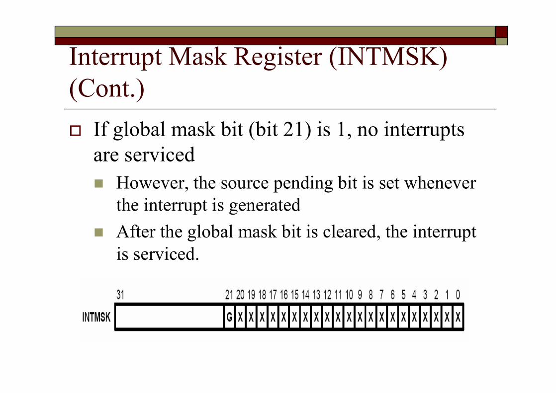
Interrupt Mask Register (INTMSK) (Cont.)o If global mask bit (bit 21) is 1, no interrupts
are servicedn However, the source pending bit is set whenever
the interrupt is generatedn After the global mask bit is cleared, the interrupt
is serviced.

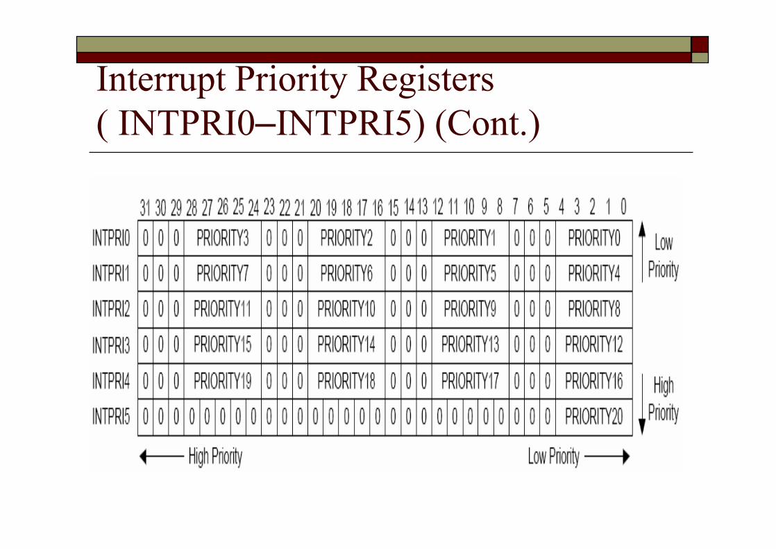
Interrupt Priority Registers ( INTPRI0–INTPRI5)o Contain information about which interrupt source is
assigned to the pre-defined interrupt priorityo Each INTPRIn register value determines the priority
of the corresponding interrupt sourcen The lowest priority value is priority 0, and the highest
priority value is priority 20n The index value of each interrupt source is written to one
of the above 21 positionso See the next slide
Interrupt Priority Registers ( INTPRI0–INTPRI5) (Cont.)
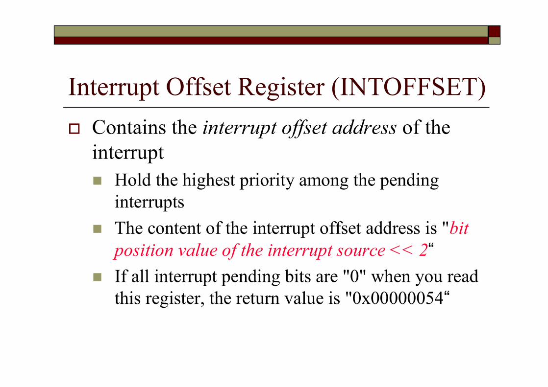
Interrupt Offset Register (INTOFFSET)o Contains the interrupt offset address of the
interruptn Hold the highest priority among the pending
interruptsn The content of the interrupt offset address is "bit
position value of the interrupt source << 2“n If all interrupt pending bits are "0" when you read
this register, the return value is "0x00000054“
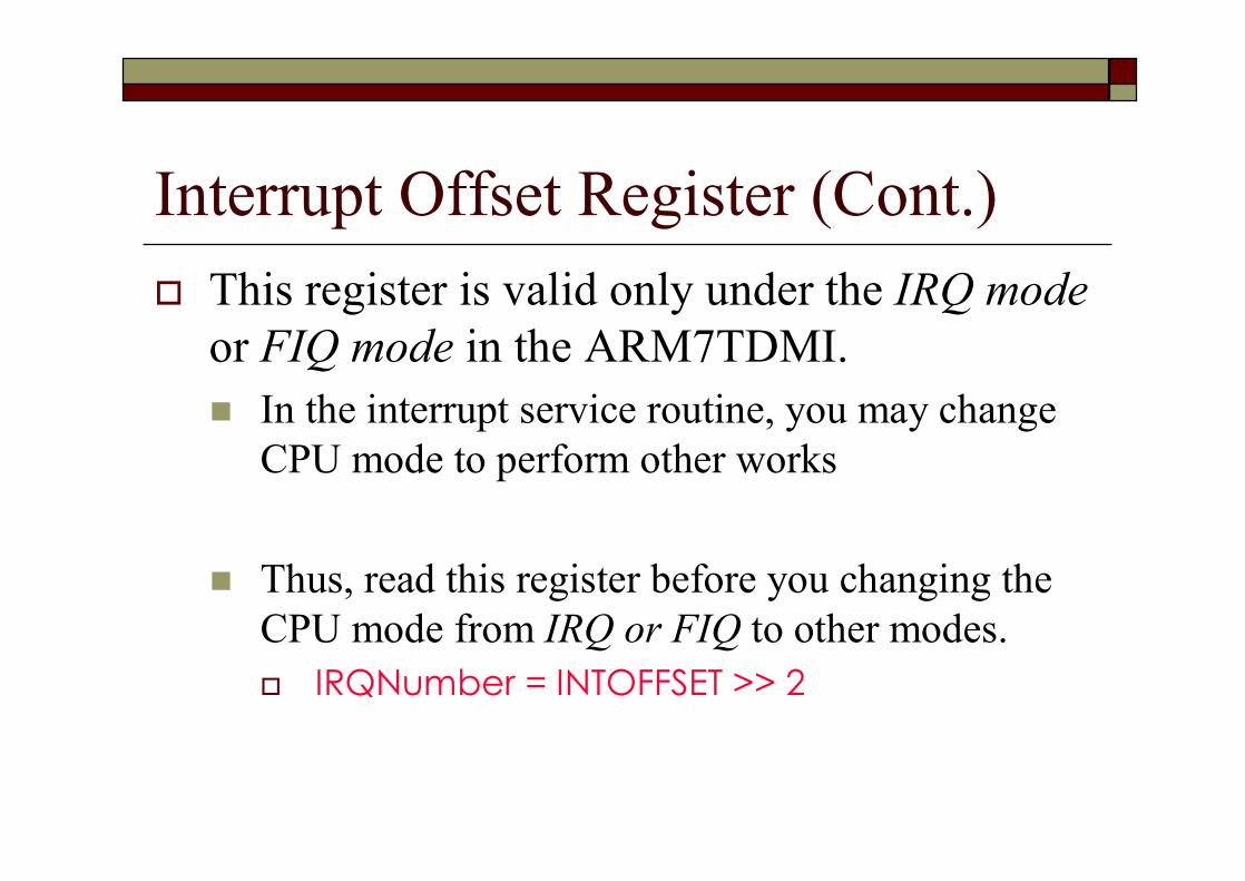
Interrupt Offset Register (Cont.)o This register is valid only under the IRQ mode
or FIQ mode in the ARM7TDMI.n In the interrupt service routine, you may change
CPU mode to perform other works
n Thus, read this register before you changing the CPU mode from IRQ or FIQ to other modes.o IRQNumber = INTOFFSET >> 2
Interrupt Offset Register (Cont.)o INTOSET_FIQ/INTOSET_IRQ register can
also be used to get the highest priority interruptn INTOSET_FIQ: FIQ interrupt offset register
n INTOSET_IRQ: IRQ interrupt offset register
IRQ Handler (Cont.)

FIQ HandlerFIQ_Handler
STMFD sp!, {r0-r7, lr}BL ISR_FiqHandlerLDMFD sp!, {r0-r7, lr}SUBS pc, lr, #4
o The same as IRQ Handlern Except the number of saved unbanked registers

Reset Handlero The operation depend on the system for which the
software is being developedo For example
n Initialize stacks and registers.n Initialize the memory system, if using an MMU.n Initialize any critical I/O devices.n Enable interrupts.n Change processor mode and/or state.n Initialize variables required by C and call the main
application
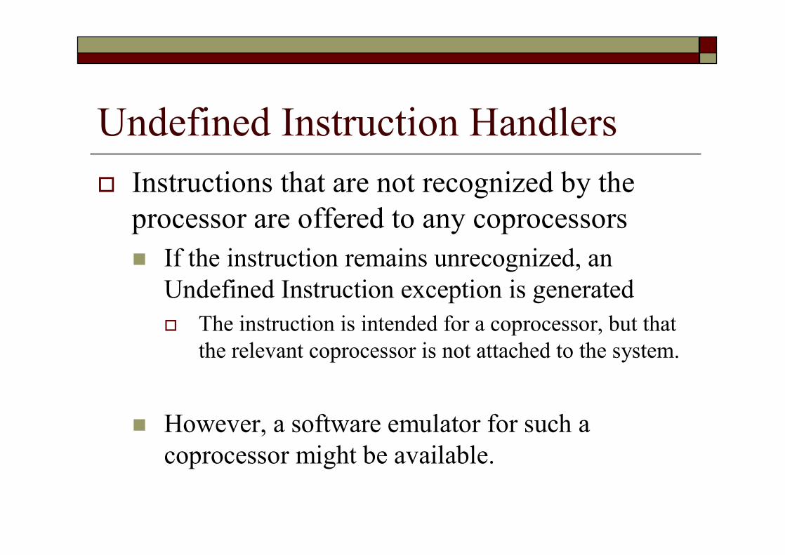
Undefined Instruction Handlerso Instructions that are not recognized by the
processor are offered to any coprocessors n If the instruction remains unrecognized, an
Undefined Instruction exception is generatedo The instruction is intended for a coprocessor, but that
the relevant coprocessor is not attached to the system.
n However, a software emulator for such a coprocessor might be available.

Software Emulatoro Attach itself to the Undefined Instruction vector and
store the old contents.o Examine the undefined instruction to see if it should
be emulated. n If bits 27 to 24 = b1110 or b110x,
o The instruction is a coprocessor instructionn Bits 8-11: CP# (Co-Process Number)
o Specify which coprocessor is being called upon
o If not, the emulator passes the exception onto the original handler or the next emulator in the chain
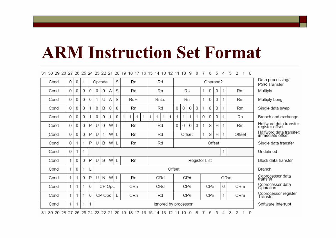
ARM Instruction Set Format

Prefetch Aborto If the system has no MMU
n The Prefetch Abort handler can simply report the error and quit
o Otherwisen The address that caused the abort must be restored into
physical memoryo In both cases, the handler must return to the
instruction causing the prefetch abort exceptionn SUBS pc, lr, #4
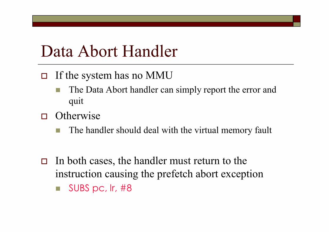
Data Abort Handlero If the system has no MMU
n The Data Abort handler can simply report the error and quit
o Otherwisen The handler should deal with the virtual memory fault
o In both cases, the handler must return to the instruction causing the prefetch abort exceptionn SUBS pc, lr, #8
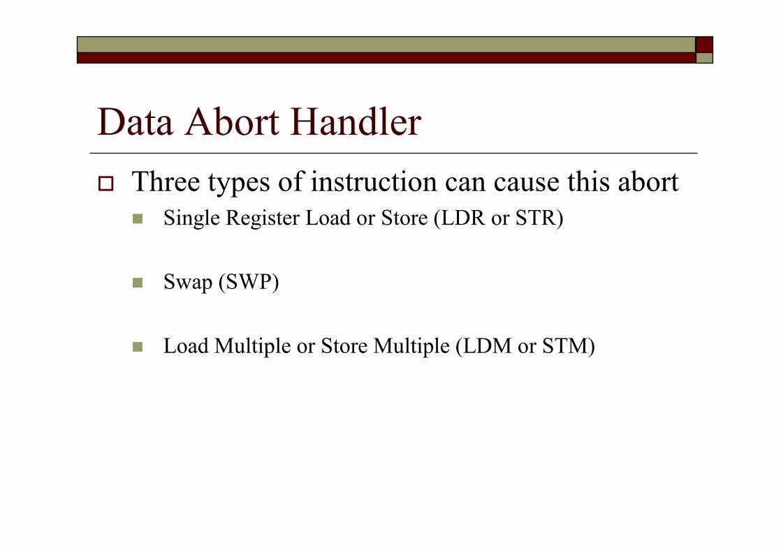
Data Abort Handlero Three types of instruction can cause this abort
n Single Register Load or Store (LDR or STR)
n Swap (SWP)
n Load Multiple or Store Multiple (LDM or STM)

Referenceo Sansung S3C4510B User’s Manual
n Chapter 13 Interrupt Controllern http://www.samsung.com/Products/Semiconductor/Syste
mLSI/Networks/PersonalNTASSP/CommunicationProcessor/S3C4510B/S3C4510B.htm
o Sansung S3C4510B application notesn http://www.samsung.com/Products/Semiconductor/Syste
mLSI/Networks/PersonalNTASSP/CommunicationProcessor/S3C4510B/S3C4510B.htm
o ARM® Developer Suite: Developer Guiden Chapter 5: Handing Processor Exceptions