Embed Size (px)
Citation preview
Chapter 7:
Components of Optical
Instruments
** This presentation contains data from several books and open access internet sources. It can
only be used for non-profit education purposes.
Chem 305- Instrumental Analysis course notes by Prof. Dr. Şerife H. Yalçın
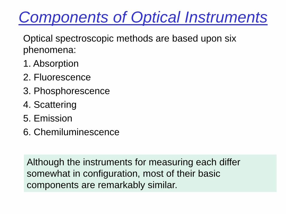
Components of Optical Instruments
Optical spectroscopic methods are based upon six
phenomena:
1. Absorption
2. Fluorescence
3. Phosphorescence
4. Scattering
5. Emission
6. Chemiluminescence
Although the instruments for measuring each differ
somewhat in configuration, most of their basic
components are remarkably similar.
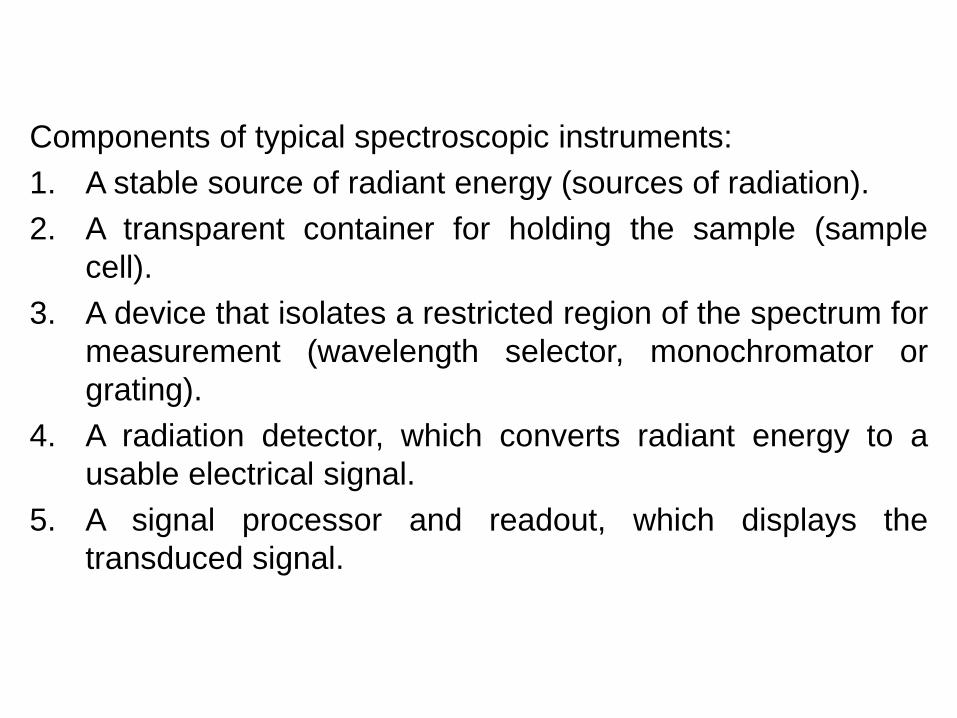
Components of typical spectroscopic instruments:
1. A stable source of radiant energy (sources of radiation).
2. A transparent container for holding the sample (sample
cell).
3. A device that isolates a restricted region of the spectrum for
measurement (wavelength selector, monochromator or
grating).
4. A radiation detector, which converts radiant energy to a
usable electrical signal.
5. A signal processor and readout, which displays the
transduced signal.
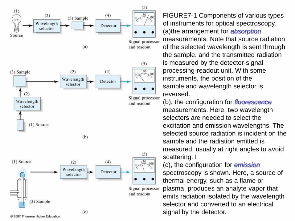
FIGURE7-1 Components of various types
of instruments for optical spectroscopy.
(a)the arrangement for absorption
measurements. Note that source radiation
of the selected wavelength is sent through
the sample, and the transmitted radiation
is measured by the detector-signal
processing-readout unit. With some
instruments, the position of the
sample and wavelength selector is
reversed.
(b), the configuration for fluorescence
measurements. Here, two wavelength
selectors are needed to select the
excitation and emission wavelengths. The
selected source radiation is incident on the
sample and the radiation emitted is
measured, usually at right angles to avoid
scattering. I
(c), the configuration for emission
spectroscopy is shown. Here, a source of
thermal energy, such as a flame or
plasma, produces an analyte vapor that
emits radiation isolated by the wavelength
selector and converted to an electrical
signal by the detector.
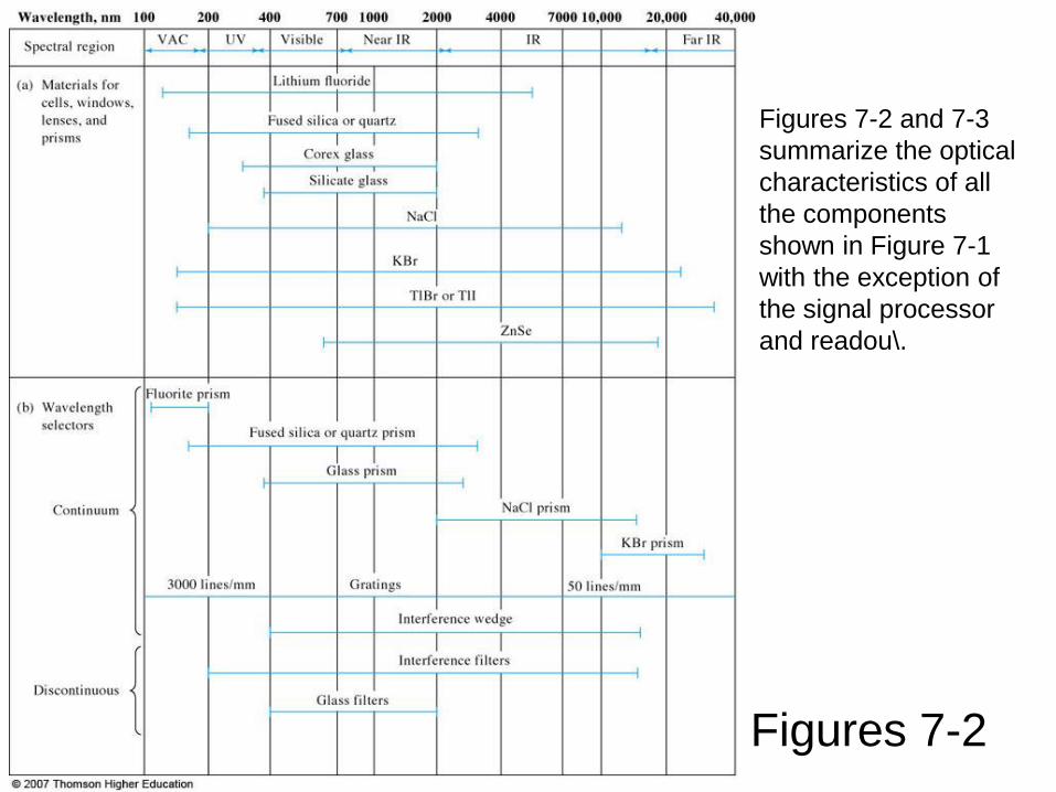
Figures 7-2 and 7-3
summarize the optical
characteristics of all
the components
shown in Figure 7-1
with the exception of
the signal processor
and readou\.
Figures 7-2
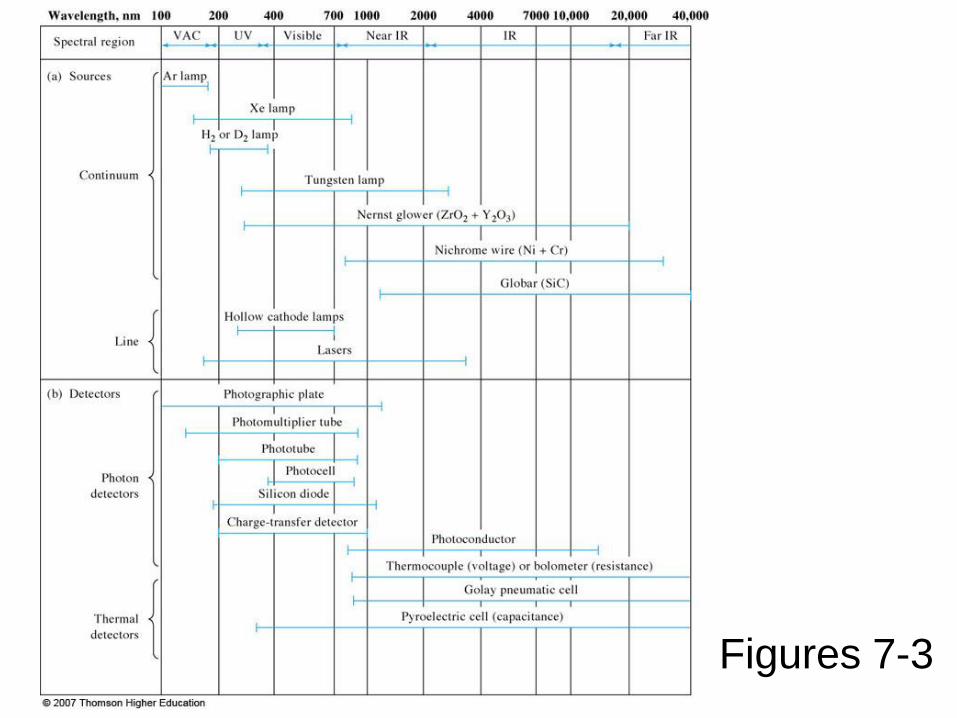
Figures 7-3
Sources of Radiation
* In order to be suitable for spectroscopic studies, a source
- must generate a beam of radiation with sufficient power for
easy detection and measurement,
- output power should be stable for reasonable periods.
* Sources are of two types.
1. Continuum sources
2. Line Sources
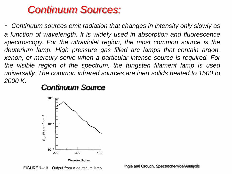
Continuum Sources:
- Continuum sources emit radiation that changes in intensity only slowly as
a function of wavelength. It is widely used in absorption and fluorescence
spectroscopy. For the ultraviolet region, the most common source is the
deuterium lamp. High pressure gas filled arc lamps that contain argon,
xenon, or mercury serve when a particular intense source is required. For
the visible region of the spectrum, the tungsten filament lamp is used
universally. The common infrared sources are inert solids heated to 1500 to
2000 K. Continuum Source
Ingle and Crouch, Spectrochemical Analysis
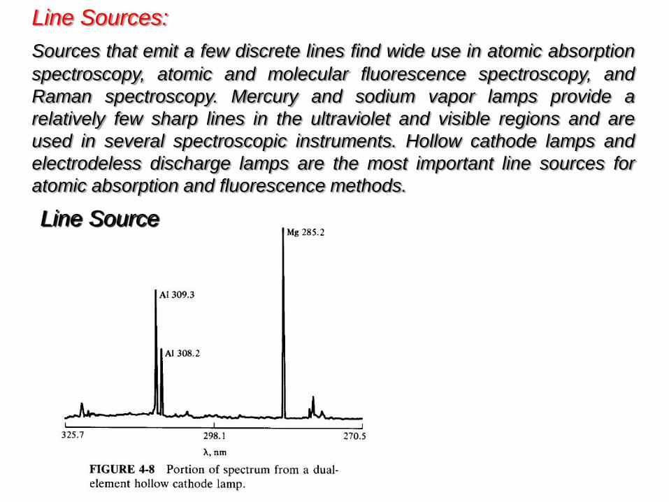
Line Sources:
Sources that emit a few discrete lines find wide use in atomic absorption
spectroscopy, atomic and molecular fluorescence spectroscopy, and
Raman spectroscopy. Mercury and sodium vapor lamps provide a
relatively few sharp lines in the ultraviolet and visible regions and are
used in several spectroscopic instruments. Hollow cathode lamps and
electrodeless discharge lamps are the most important line sources for
atomic absorption and fluorescence methods.
Line Source
Laser Sources
* The term ‘LASER’ is an acronym for Light Amplification by
Stimulated Emission of Radiation.
* The first laser was introduced in 1960 and since then too many,
highly important applications of lasers in chemistry were described.
* Laser are highly useful because of their
- very high intensities,
- narrow bandwidths,
- single wavelength, and
- coherent radiation.
* Laser are widely used in high-resolution spectroscopy.
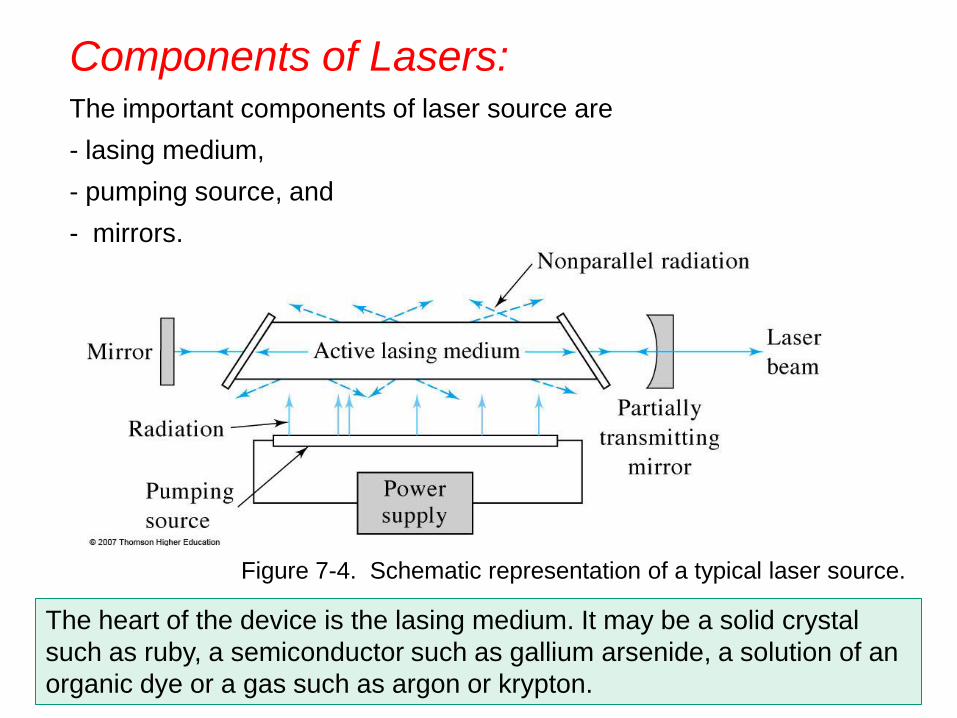
Components of Lasers: The important components of laser source are
- lasing medium,
- pumping source, and
- mirrors.
The heart of the device is the lasing medium. It may be a solid crystal
such as ruby, a semiconductor such as gallium arsenide, a solution of an
organic dye or a gas such as argon or krypton.
Figure 7-4. Schematic representation of a typical laser source.
Four processes in Lasing Mechanism:
1. Pumping
2. Spontaneous emission (fluorescence)
3. Stimulated emission
4. Absorption
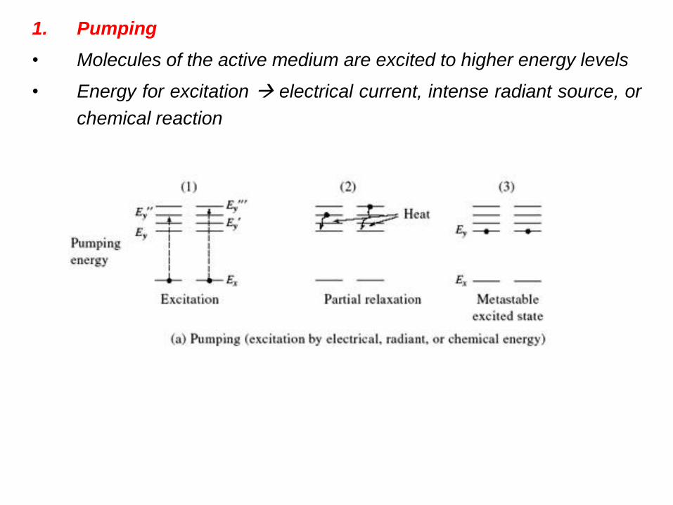
1. Pumping
• Molecules of the active medium are excited to higher energy levels
• Energy for excitation electrical current, intense radiant source, or
chemical reaction
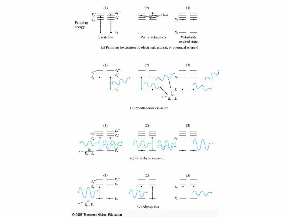
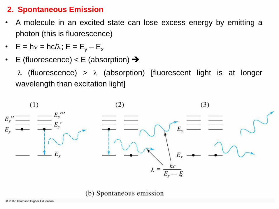
2. Spontaneous Emission
• A molecule in an excited state can lose excess energy by emitting a
photon (this is fluorescence)
• E = h = hc/; E = Ey – Ex
• E (fluorescence) < E (absorption)
(fluorescence) > (absorption) [fluorescent light is at longer
wavelength than excitation light]
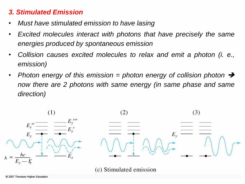
3. Stimulated Emission
• Must have stimulated emission to have lasing
• Excited molecules interact with photons that have precisely the same
energies produced by spontaneous emission
• Collision causes excited molecules to relax and emit a photon (i. e.,
emission)
• Photon energy of this emission = photon energy of collision photon
now there are 2 photons with same energy (in same phase and same
direction)
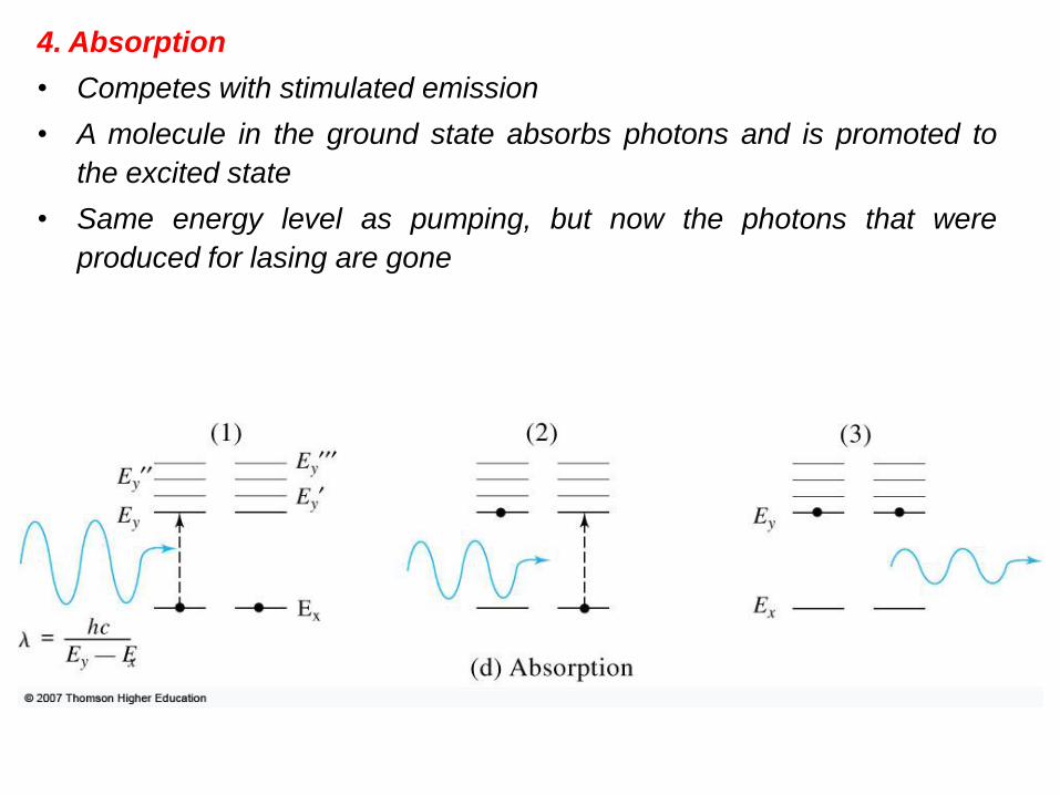
4. Absorption
• Competes with stimulated emission
• A molecule in the ground state absorbs photons and is promoted to
the excited state
• Same energy level as pumping, but now the photons that were
produced for lasing are gone
Population Inversion:
• To have light amplification in a laser, the number of photons produced by
stimulated emission must exceed the number lost by absorption.
• Must have population inversion to sustain lasing.
• Population of molecules is inverted (relative to how the population
normally exists).
• Normally: there are more molecules in the ground state than in the
excited state (need > 50 %).
• Population inversion: More molecules in the excited state than in the
ground state.
Why is it important?
– More molecules in the ground state more molecules that can
absorb photons
– Remember: absorption competes with stimulated emission
– Light is attenuated rather than amplified
– More molecules in the excited state net gain in photons produced
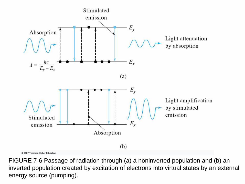
FIGURE 7-6 Passage of radiation through (a) a noninverted population and (b) an
inverted population created by excitation of electrons into virtual states by an external
energy source (pumping).
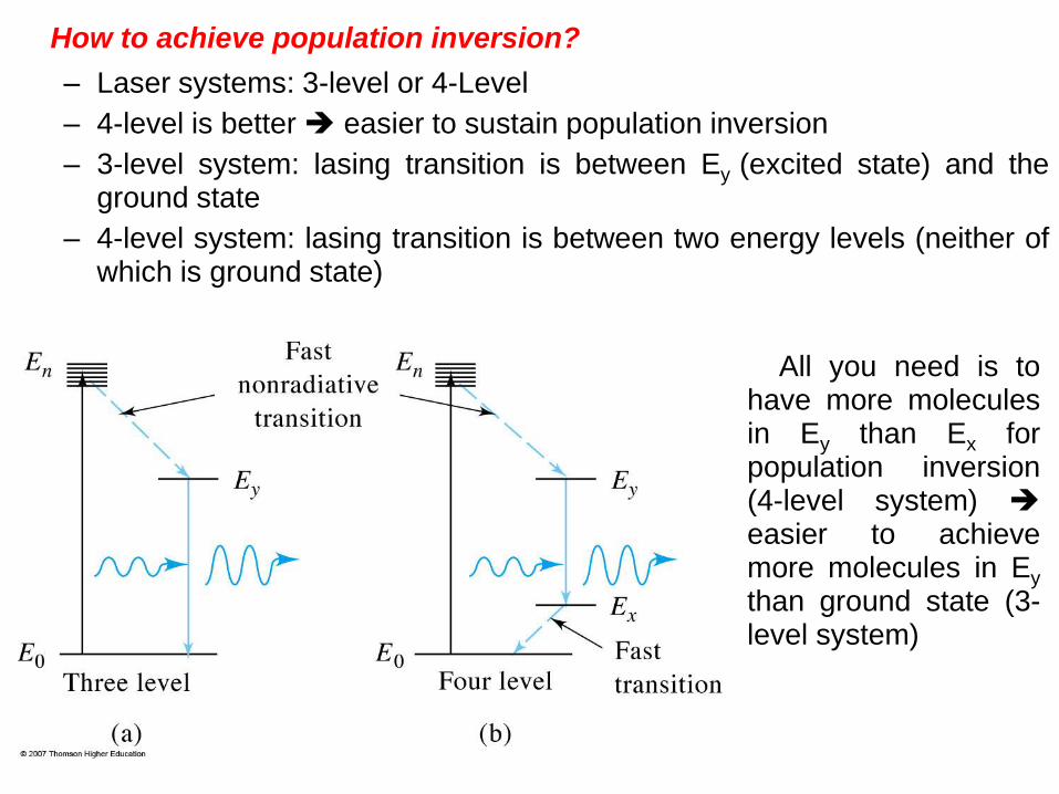
How to achieve population inversion?
– Laser systems: 3-level or 4-Level
– 4-level is better easier to sustain population inversion
– 3-level system: lasing transition is between Ey (excited state) and the ground state
– 4-level system: lasing transition is between two energy levels (neither of which is ground state)
All you need is to have more molecules in Ey than Ex for population inversion (4-level system) easier to achieve more molecules in Ey than ground state (3-level system)
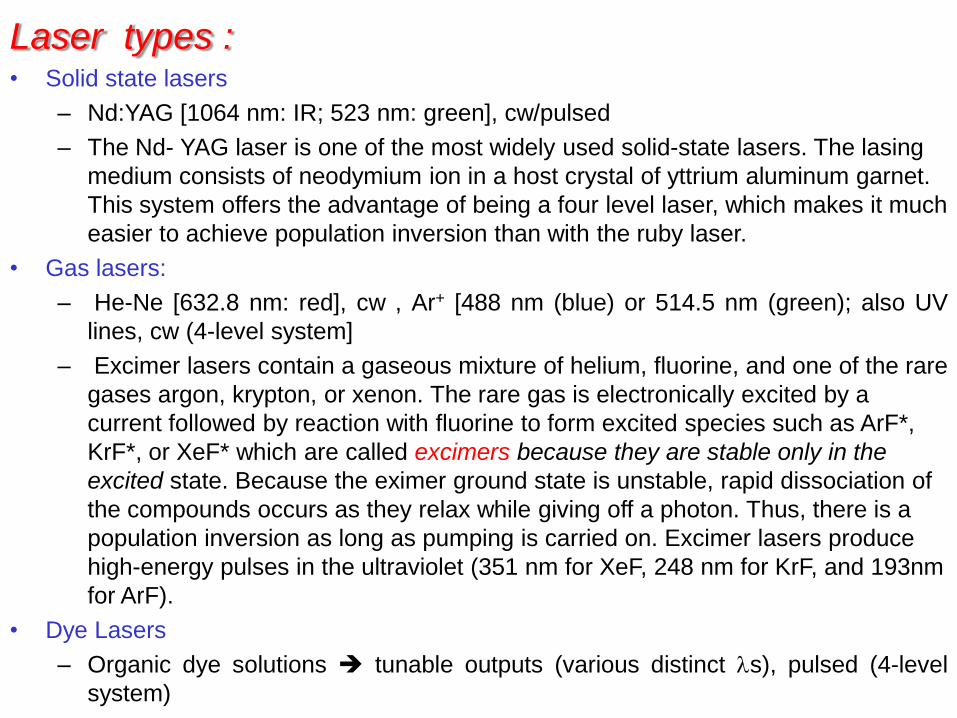
Laser types : • Solid state lasers
– Nd:YAG [1064 nm: IR; 523 nm: green], cw/pulsed
– The Nd- YAG laser is one of the most widely used solid-state lasers. The lasing
medium consists of neodymium ion in a host crystal of yttrium aluminum garnet.
This system offers the advantage of being a four level laser, which makes it much
easier to achieve population inversion than with the ruby laser.
• Gas lasers:
– He-Ne [632.8 nm: red], cw , Ar+ [488 nm (blue) or 514.5 nm (green); also UV
lines, cw (4-level system]
– Excimer lasers contain a gaseous mixture of helium, fluorine, and one of the rare
gases argon, krypton, or xenon. The rare gas is electronically excited by a
current followed by reaction with fluorine to form excited species such as ArF*,
KrF*, or XeF* which are called excimers because they are stable only in the
excited state. Because the eximer ground state is unstable, rapid dissociation of
the compounds occurs as they relax while giving off a photon. Thus, there is a
population inversion as long as pumping is carried on. Excimer lasers produce
high-energy pulses in the ultraviolet (351 nm for XeF, 248 nm for KrF, and 193nm
for ArF).
• Dye Lasers
– Organic dye solutions tunable outputs (various distinct s), pulsed (4-level
system)
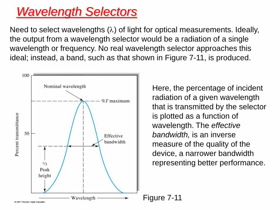
Need to select wavelengths () of light for optical measurements. Ideally,
the output from a wavelength selector would be a radiation of a single
wavelength or frequency. No real wavelength selector approaches this
ideal; instead, a band, such as that shown in Figure 7-11, is produced.
Wavelength Selectors
Figure 7-11
Here, the percentage of incident
radiation of a given wavelength
that is transmitted by the selector
is plotted as a function of
wavelength. The effective
bandwidth, is an inverse
measure of the quality of the
device, a narrower bandwidth
representing better performance.
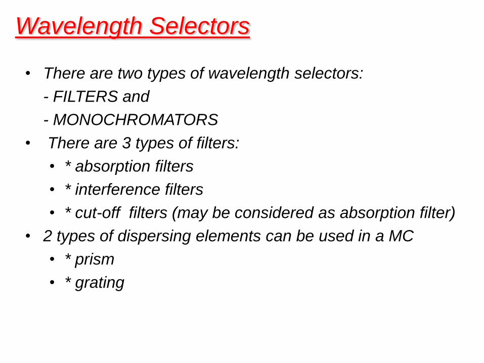
• There are two types of wavelength selectors:
- FILTERS and
- MONOCHROMATORS
• There are 3 types of filters:
• * absorption filters
• * interference filters
• * cut-off filters (may be considered as absorption filter)
• 2 types of dispersing elements can be used in a MC
• * prism
• * grating
Wavelength Selectors
- Simple, rugged (no moving parts in general)
- Relatively inexpensive
- Can select some broad range of wavelengths
- Most often used in ;
- field instruments
- simpler instruments
- instruments dedicated to monitoring a single wavelength
range.
FILTERS
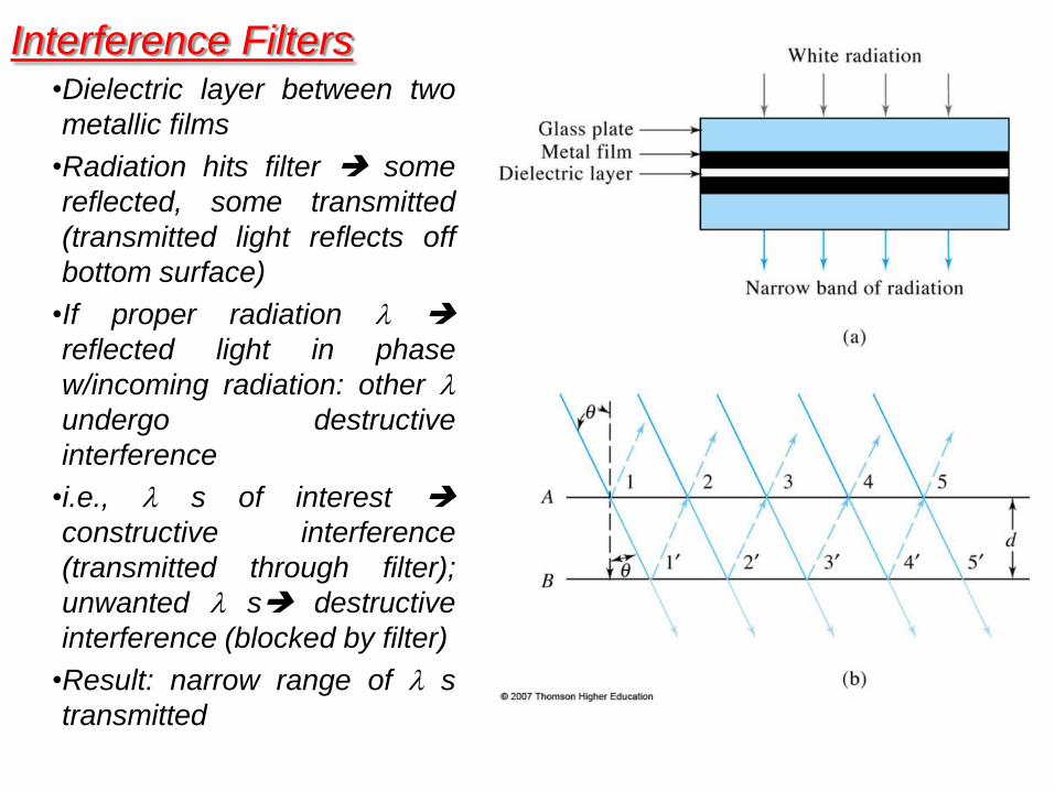
Interference Filters •Dielectric layer between two
metallic films
•Radiation hits filter some
reflected, some transmitted
(transmitted light reflects off
bottom surface)
•If proper radiation
reflected light in phase
w/incoming radiation: other
undergo destructive
interference
•i.e., s of interest
constructive interference
(transmitted through filter);
unwanted s destructive
interference (blocked by filter)
•Result: narrow range of s
transmitted
Interference Filters
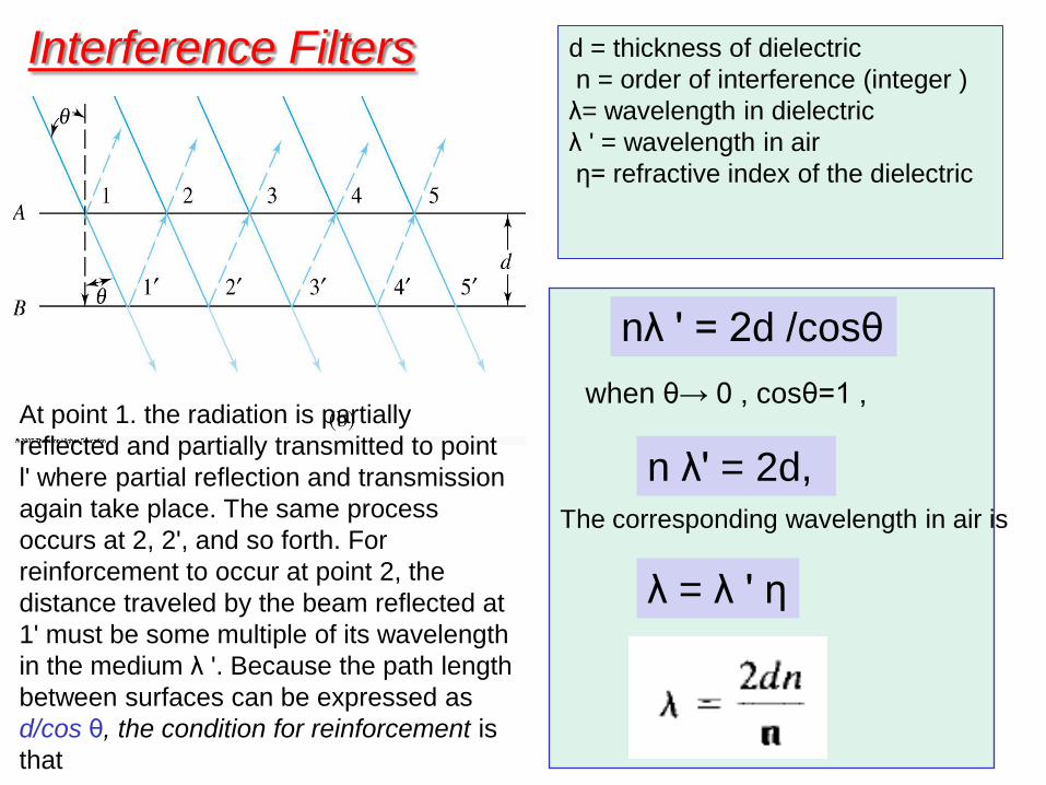
At point 1. the radiation is partially
reflected and partially transmitted to point
l' where partial reflection and transmission
again take place. The same process
occurs at 2, 2', and so forth. For
reinforcement to occur at point 2, the
distance traveled by the beam reflected at
1' must be some multiple of its wavelength
in the medium λ '. Because the path length
between surfaces can be expressed as
d/cos θ, the condition for reinforcement is
that
when θ→ 0 , cosθ=1 ,
nλ ' = 2d /cosθ
n λ' = 2d, The corresponding wavelength in air is
λ = λ ' η
d = thickness of dielectric
n = order of interference (integer )
λ= wavelength in dielectric
λ ' = wavelength in air
η= refractive index of the dielectric
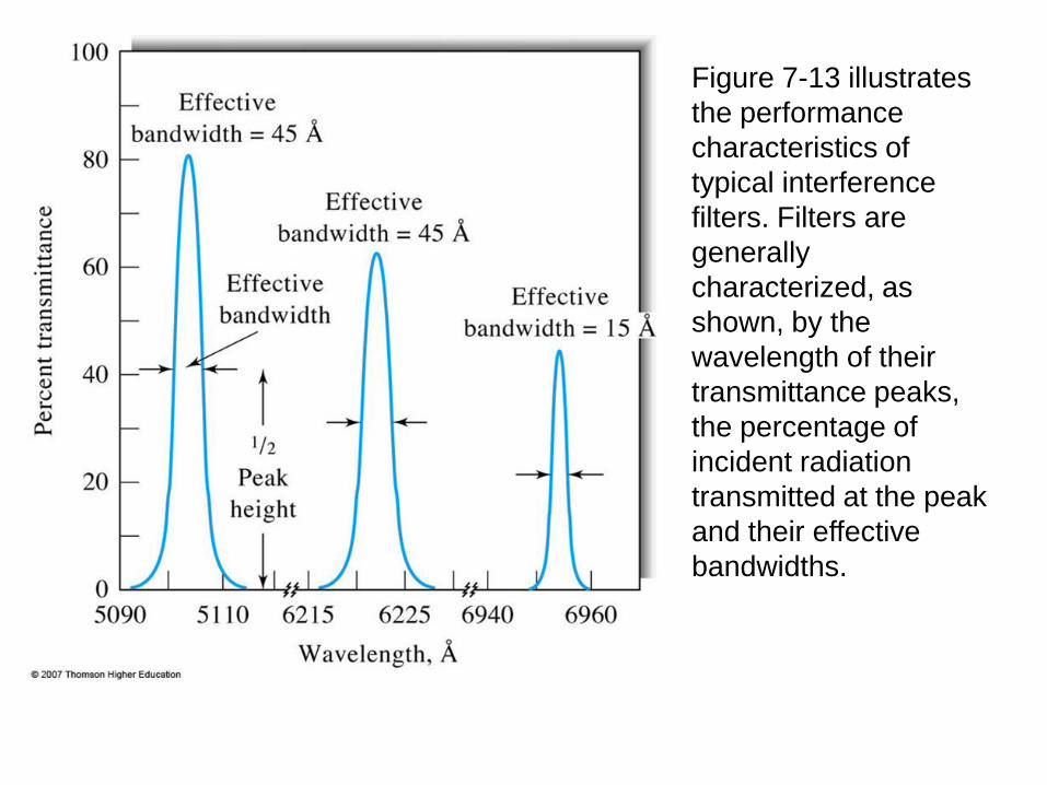
Figure 7-13 illustrates
the performance
characteristics of
typical interference
filters. Filters are
generally
characterized, as
shown, by the
wavelength of their
transmittance peaks,
the percentage of
incident radiation
transmitted at the peak
and their effective
bandwidths.
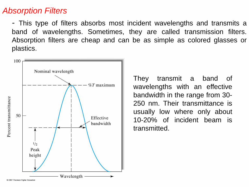
Absorption Filters
- This type of filters absorbs most incident wavelengths and transmits a
band of wavelengths. Sometimes, they are called transmission filters.
Absorption filters are cheap and can be as simple as colored glasses or
plastics.
They transmit a band of
wavelengths with an effective
bandwidth in the range from 30-
250 nm. Their transmittance is
usually low where only about
10-20% of incident beam is
transmitted.
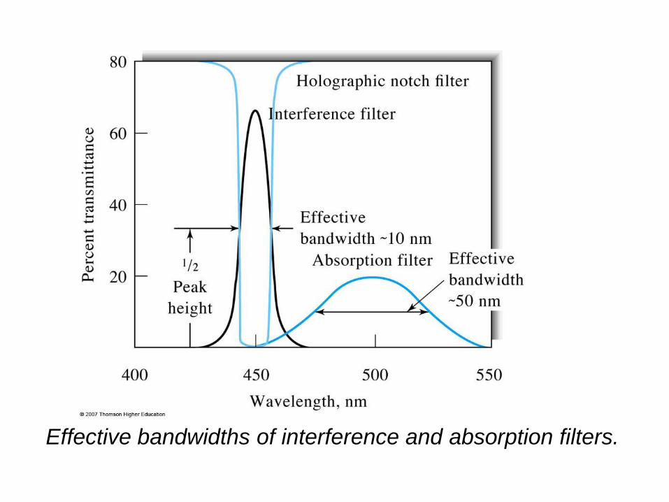
Effective bandwidths of interference and absorption filters.
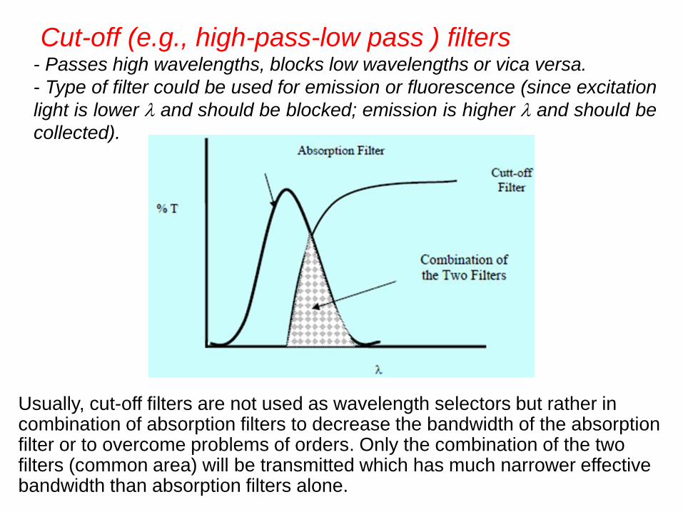
Cut-off (e.g., high-pass-low pass ) filters - Passes high wavelengths, blocks low wavelengths or vica versa.
- Type of filter could be used for emission or fluorescence (since excitation
light is lower and should be blocked; emission is higher and should be
collected).
Usually, cut-off filters are not used as wavelength selectors but rather in combination of absorption filters to decrease the bandwidth of the absorption filter or to overcome problems of orders. Only the combination of the two filters (common area) will be transmitted which has much narrower effective bandwidth than absorption filters alone.
Monochromators
- For many spectroscopic methods, it is necessary or
desirable to be able to continuously vary the wavelength
of radiation over a broad range. This process is called
scanning a spectrum.
- Monochromators are designed for spectral scanning.
Monochromators for ultraviolet, visible, and infrared
radiation are all similar in mechanical construction in the
sense that they use slits, lenses, mirrors, windows, and
gratings or prisms.
- The materials from which these components are
fabricated depend on the wavelength region of intended
use.
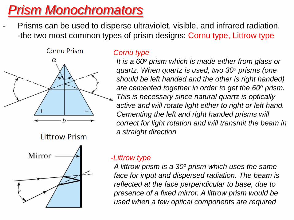
Prism Monochromators - Prisms can be used to disperse ultraviolet, visible, and infrared radiation.
-the two most common types of prism designs: Cornu type, Littrow type
Cornu type
It is a 60o prism which is made either from glass or
quartz. When quartz is used, two 30o prisms (one
should be left handed and the other is right handed)
are cemented together in order to get the 60o prism.
This is necessary since natural quartz is optically
active and will rotate light either to right or left hand.
Cementing the left and right handed prisms will
correct for light rotation and will transmit the beam in
a straight direction
-Littrow type
A littrow prism is a 30o prism which uses the same
face for input and dispersed radiation. The beam is
reflected at the face perpendicular to base, due to
presence of a fixed mirror. A littrow prism would be
used when a few optical components are required
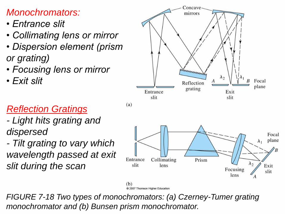
Monochromators:
• Entrance slit
• Collimating lens or mirror
• Dispersion element (prism
or grating)
• Focusing lens or mirror
• Exit slit
FIGURE 7-18 Two types of monochromators: (a) Czerney-Tumer grating
monochromator and (b) Bunsen prism monochromator.
Reflection Gratings
- Light hits grating and
dispersed
- Tilt grating to vary which
wavelength passed at exit
slit during the scan
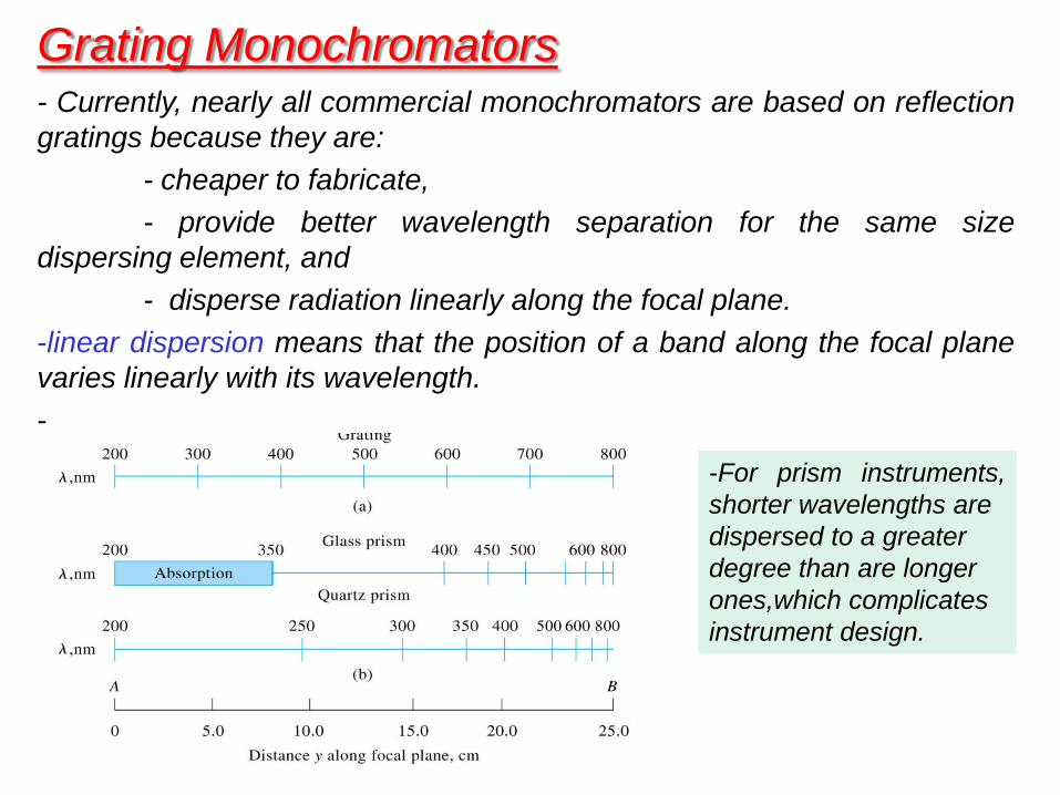
Grating Monochromators - Currently, nearly all commercial monochromators are based on reflection
gratings because they are:
- cheaper to fabricate,
- provide better wavelength separation for the same size
dispersing element, and
- disperse radiation linearly along the focal plane.
-linear dispersion means that the position of a band along the focal plane
varies linearly with its wavelength.
-
-For prism instruments,
shorter wavelengths are
dispersed to a greater
degree than are longer
ones,which complicates
instrument design.
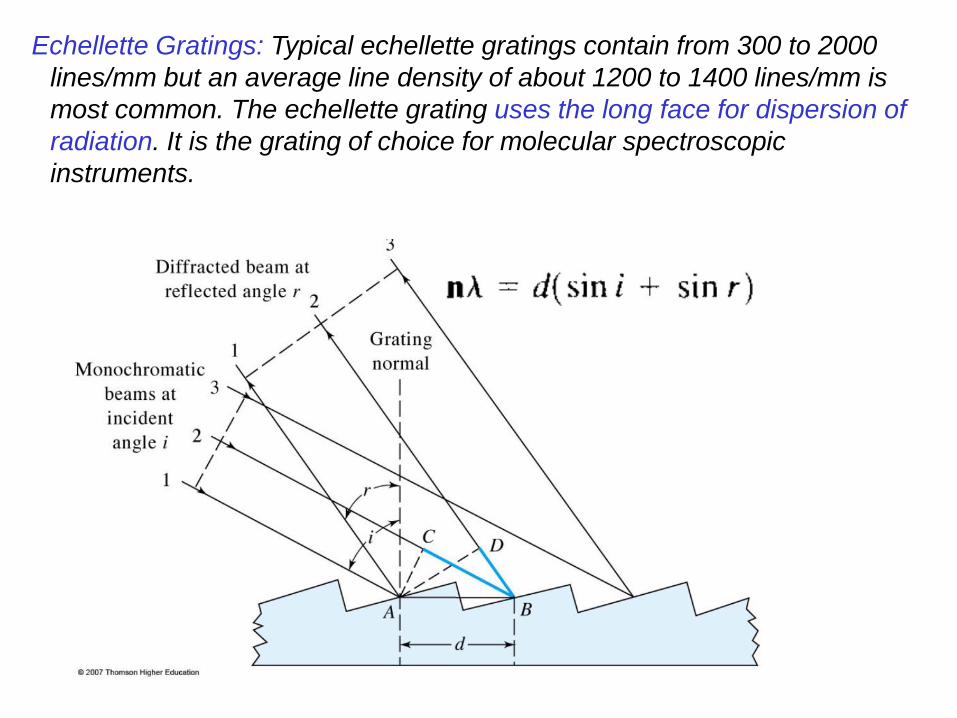
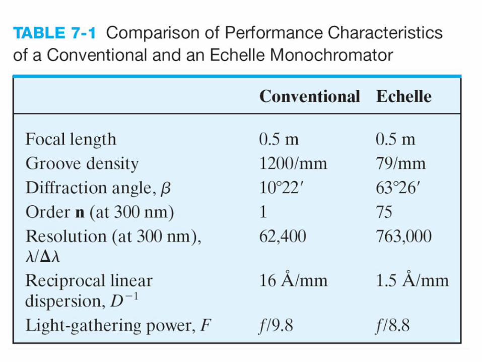
Echellette Gratings: Typical echellette gratings contain from 300 to 2000
lines/mm but an average line density of about 1200 to 1400 lines/mm is
most common. The echellette grating uses the long face for dispersion of
radiation. It is the grating of choice for molecular spectroscopic
instruments.
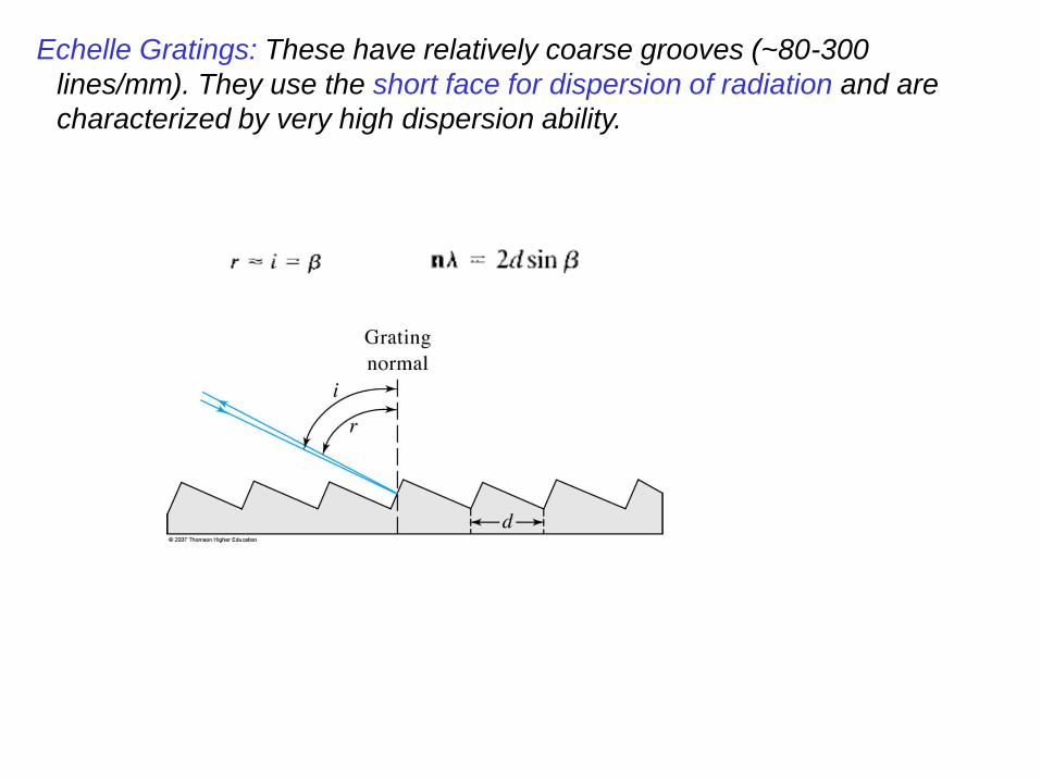
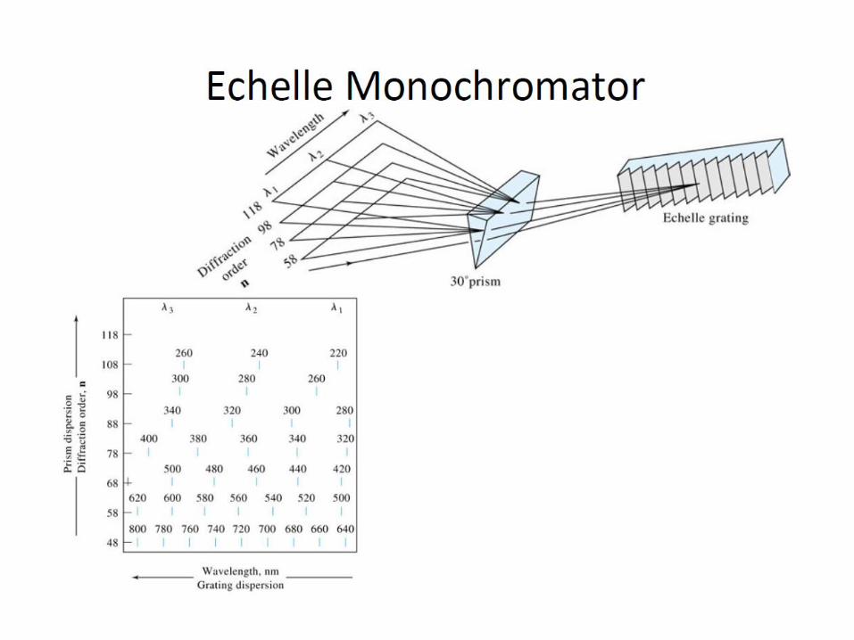
Echelle Gratings: These have relatively coarse grooves (~80-300
lines/mm). They use the short face for dispersion of radiation and are
characterized by very high dispersion ability.
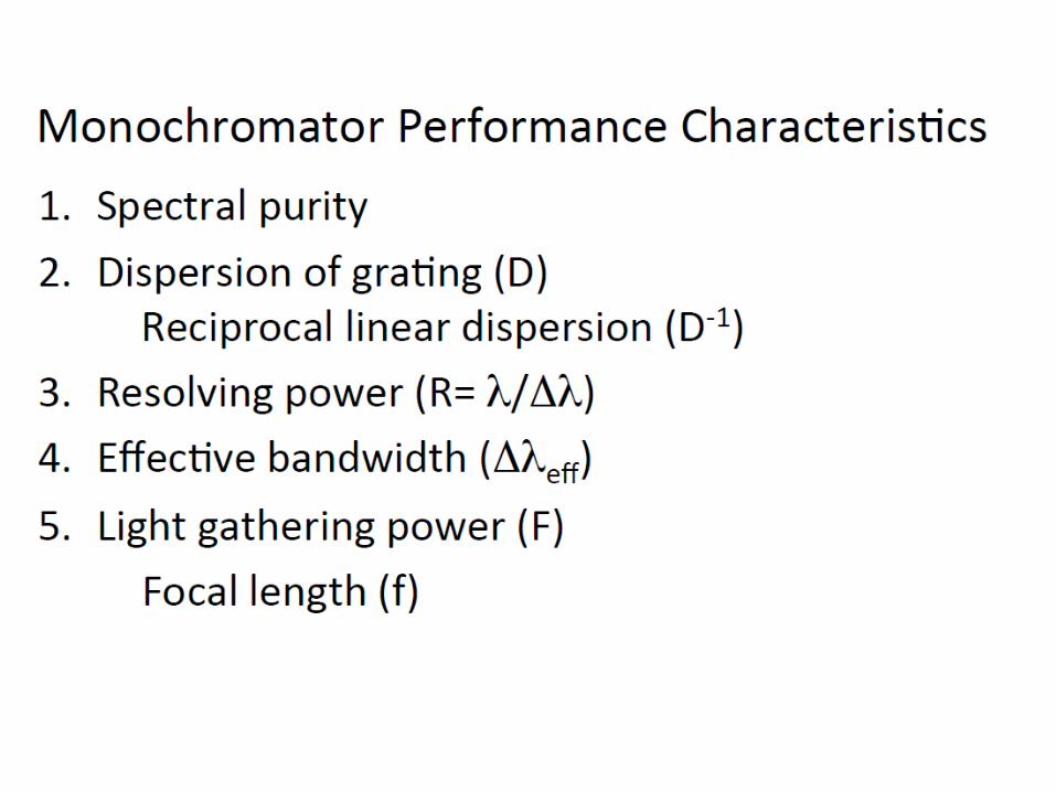
Performance Characteristics of Grating MC
Four main properties can assess the performance of grating MC
1. Spectral Purity
If the exiting beam is thoroughly studied, it will always be observed that it
is contaminated with small amounts of wavelengths far from that of the
instrumental setting. This is mainly due to the following reasons:
a) Scattered radiation due to presence of dust particulates inside the monochromator as well as on various optical surfaces. This drawback can be overcome by sealing the monochromator entrance and exit slits by suitable windows.
b) Stray radiation which is radiation that exits the monochromator without passing through the dispersion element. This problem as well as all other problems related to spurious radiation, including scattering, can be largely eliminated by introducing baffles at appropriate locations inside the monochromator, as well as painting the internal walls of the monochromator by a black paint.
c) Imperfections of monochromator components, like broken or uneven blazes, uneven lens or mirror surfaces, etc, would lead to important problems regarding the quality of obtained wavelengths.
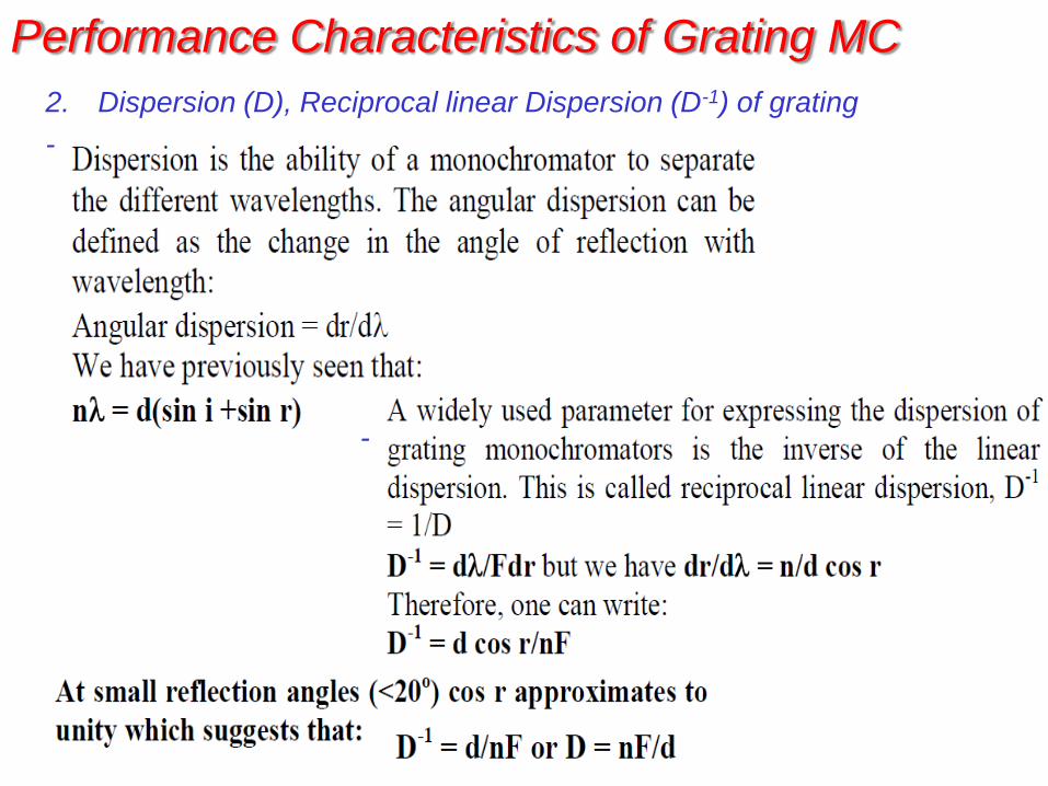
2. Dispersion (D), Reciprocal linear Dispersion (D-1) of grating
-
-
Performance Characteristics of Grating MC
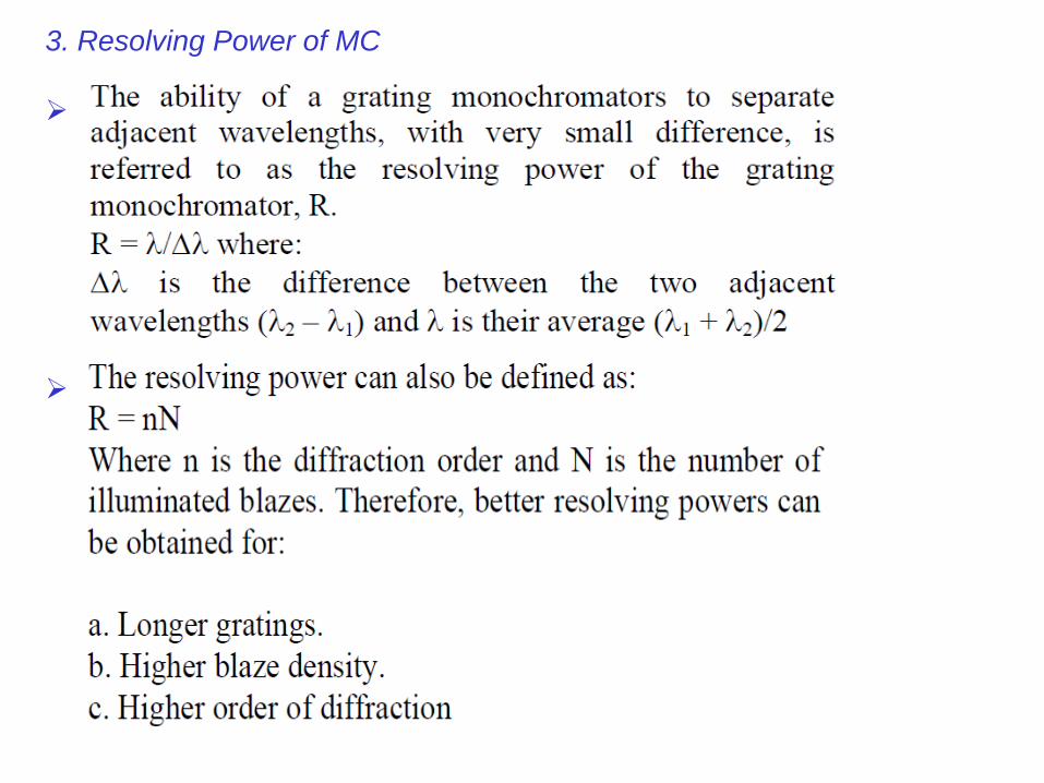
3. Resolving Power of MC
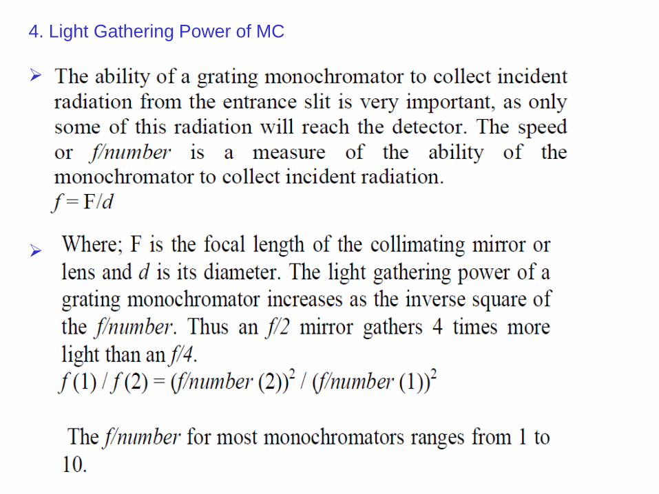
4. Light Gathering Power of MC
Monochromator Slits
A slit is machined from two pieces of metal to give sharp
edges that are exactly aligned (same plane) and parallel
Since the effective bandwidth of a monochromator is
dependent on its dispersion (Dleff = wD-1) and the slit width,
careful choice of the slit width must be done
A narrower slit should be preferred for best wavelengths
resolution. However, as the slit width gets narrower, the radiant
power reaching the detector will decrease, which is too bad for
quantitative analysis. Overall, adjustment of the slit width is a
compromise between detectability and resolution
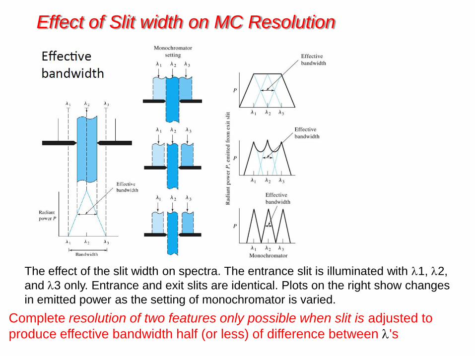
Effect of Slit width on MC Resolution
The effect of the slit width on spectra. The entrance slit is illuminated with 1, 2,
and 3 only. Entrance and exit slits are identical. Plots on the right show changes
in emitted power as the setting of monochromator is varied.
Complete resolution of two features only possible when slit is adjusted to
produce effective bandwidth half (or less) of difference between 's
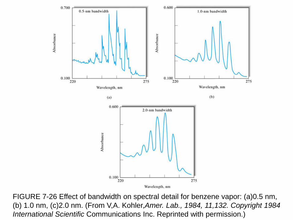
FIGURE 7-26 Effect of bandwidth on spectral detail for benzene vapor: (a)0.5 nm,
(b) 1.0 nm, (c)2.0 nm. (From V,A. Kohler,Amer. Lab., 1984, 11,132. Copyright 1984
International Scientific Communications Inc. Reprinted with permission.)
Sample Containers and Optics
- The cells or cuvettes that hold the samples must be made
of material that is transparent to radiation in the spectral
region of interest.
- Quartz or fused silica is required for work in the ultraviolet
region (below 350 nm), both of these substances are
transparent in the visible region.
- Silicate glasses can be employed in the region between
350 and 2000 nm.
- Plastic containers can be used in the visible region.
- Crystalline NaCl is the most common cell windows in the
IR region.
Radiation Transducers:
The detectors for early spectroscopic instruments were the human
eye or a photographic plate or film. Nowadays more modern detectors
are in use that convert radiant energy into electrical signal.
What do we want in a transducer? Ideal transducer
– High sensitivity
– High S/N (low noise)
– Constant response over many ’s (wide range of
wavelength)
– Fast response time
– S = 0 if no light present (low dark current)
– Signal P (where P = radiant power)
• Rugged, cheap and simple
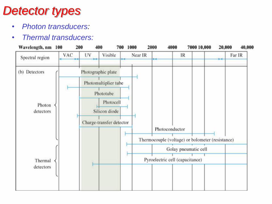
Detector types
• Photon transducers:
• Thermal transducers:
Photon Transducers:
• Respond to incident photon rate
• Highly variable spectral response (determined by photosensitive
material)
• Respond quickly (microseconds or faster)
• Single or multi channel (1-D or 2-D)
• Used largely for measurement of UV-Vis radiation
• Phototransducers are not applicable in infrared because photons
in this region lack the energy to cause photoemission of
electrons.
• Photon transducers are:
– photovoltaic cells,
– phototubes,
– photomultiplier tubes,
– photoconductivity transducers,
– silicon photodiodes,
– charge-transfer transducers
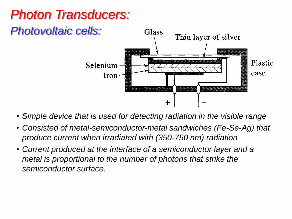
Photovoltaic cells:
• Simple device that is used for detecting radiation in the visible range
• Consisted of metal-semiconductor-metal sandwiches (Fe-Se-Ag) that
produce current when irradiated with (350-750 nm) radiation
• Current produced at the interface of a semiconductor layer and a
metal is proportional to the number of photons that strike the
semiconductor surface.
Photon Transducers:
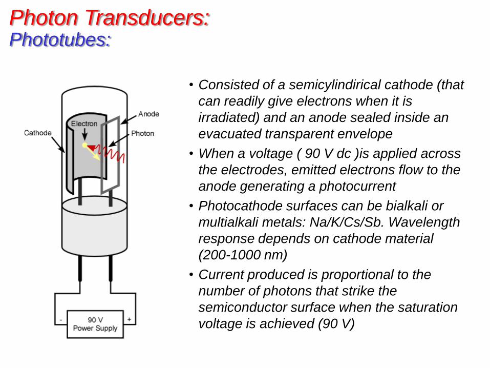
• Consisted of a semicylindirical cathode (that
can readily give electrons when it is
irradiated) and an anode sealed inside an
evacuated transparent envelope
• When a voltage ( 90 V dc )is applied across
the electrodes, emitted electrons flow to the
anode generating a photocurrent
• Photocathode surfaces can be bialkali or
multialkali metals: Na/K/Cs/Sb. Wavelength
response depends on cathode material
(200-1000 nm)
• Current produced is proportional to the
number of photons that strike the
semiconductor surface when the saturation
voltage is achieved (90 V)
Phototubes: Photon Transducers:
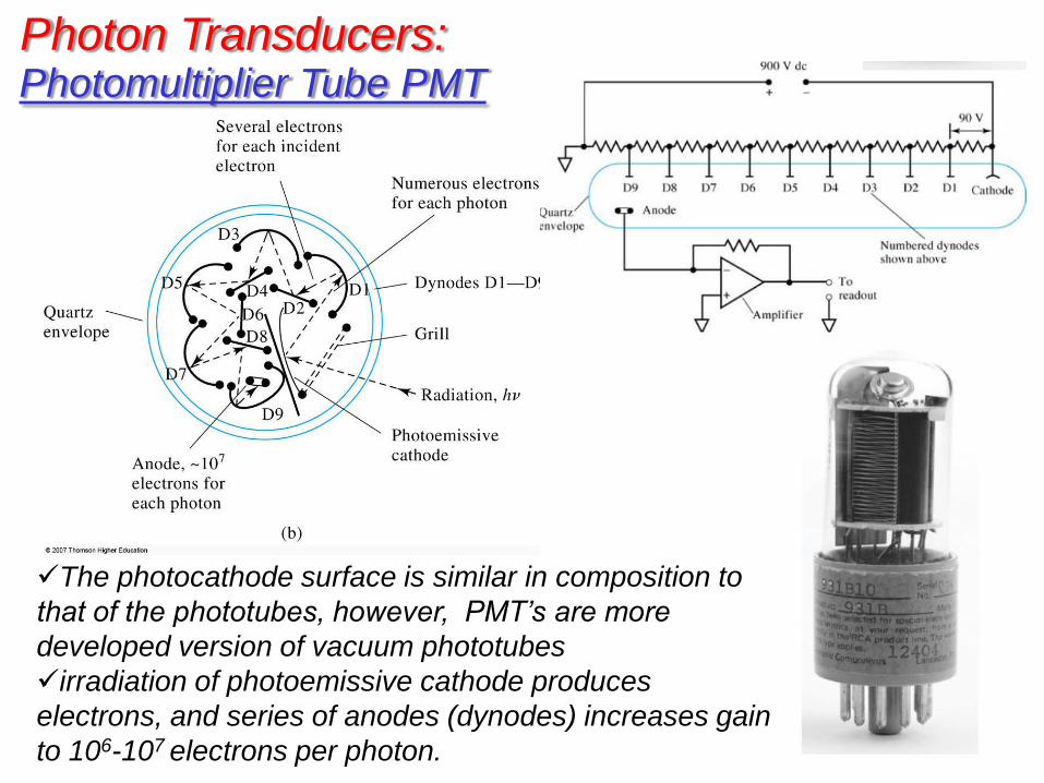
Photomultiplier Tube PMT
The photocathode surface is similar in composition to
that of the phototubes, however, PMT’s are more
developed version of vacuum phototubes
irradiation of photoemissive cathode produces
electrons, and series of anodes (dynodes) increases gain
to 106-107 electrons per photon.
Photon Transducers:
PMT-cont’d
• Extremely sensitive (used for low light applications).
• Light strikes photocathode, several electrons per photon are emitted
(~106 –107 electrons collected at the anode)
• Bias voltage applied (900 V), electrons emitted towards a more
positive dynode than photocathode (electrons attracted to it), each
electron causes emission of several electrons.
• These electrons are accelerated towards dynode #2 (90 V more
positive than dynode # 1) …etc., this process continues for 9 dynodes
• Result is the flow of electrons ~106 –107 electrons collected at the anode.
• Is there a drawback? Sensitivity usually limited by dark current.
• Dark current = current generated by thermal emission of electrons in the absence of light.
• Thermal emission can be reduced by cooling.
• Under optimal conditions, PMTs can detect single photons.
• Only used for low-light applications; it is possible to fry the photocathode.
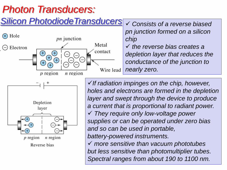
Silicon PhotodiodeTransducers Consists of a reverse biased
pn junction formed on a silicon
chip
the reverse bias creates a
depletion layer that reduces the
conductance of the junction to
nearly zero.
If radiation impinges on the chip, however,
holes and electrons are formed in the depletion
layer and swept through the device to produce
a current that is proportional to radiant power.
They require only low-voltage power
supplies or can be operated under zero bias
and so can be used in portable,
battery-powered instruments.
more sensitive than vacuum phototubes
but less sensitive than photomultiplier tubes.
Spectral ranges from about 190 to 1100 nm.
Photon Transducers:
Multichannel Photon Transducers
• Modern multichannel transducers consist of an array of small
photosensitive elements arranged either linearly or in a two-dimensional
pattern on a single semiconductor chip.
• The chip, which is usually silicon and typically has dimensions of a few
millimeters on a side, also contains electronic circuitry to provide an
output signal from each of the elements either sequentially or
simultaneously.
• For spectroscopic studies, a multichannel transducer is generally placed
in the focal plane of a spectrometer so that various elements of the
dispersed spectrum can be transduced and measured simultaneously.
• Three types of multichannel devices are used in commercial instruments
– photodiode arrays, (PDAs),
– charge-injection devices (ClDs),
– charge-coupled devices (CCDs).
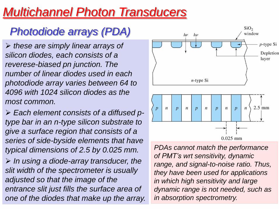
these are simply linear arrays of
silicon diodes, each consists of a
reverese-biased pn junction. The
number of linear diodes used in each
photodiode array varies between 64 to
4096 with 1024 silicon diodes as the
most common.
Each element consists of a diffused p-
type bar in an n-type silicon substrate to
give a surface region that consists of a
series of side-byside elements that have
typical dimensions of 2.5 by 0.025 mm.
In using a diode-array transducer, the
slit width of the spectrometer is usually
adjusted so that the image of the
entrance slit just fills the surface area of
one of the diodes that make up the array.
Photodiode arrays (PDA)
Multichannel Photon Transducers
PDAs cannot match the performance
of PMT’s wrt sensitivity, dynamic
range, and signal-to-noise ratio. Thus,
they have been used for applications
in which high sensitivity and large
dynamic range is not needed, such as
in absorption spectrometry.
Multichannel Photon Transducers
Charge-Transfer Devices: -charge-injection devices (ClDs),
-charge-coupled devices (CCDs)
The performance characteristics of CTDs approach or sometimes
surpass those of PMTs in addition to having the multichannel advantage
CTDs offer great sensitivity and high resolution to low light detection.
CTDs operate like a photographic film in the sense that they integrate
signal information as radiation strikes them.
The charges developed in a Si-crystal as a result of absorption of photons
are collected and measured
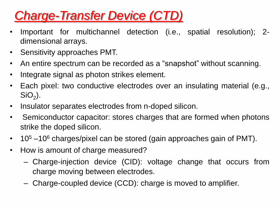
Charge-Transfer Device (CTD)
• Important for multichannel detection (i.e., spatial resolution); 2-
dimensional arrays.
• Sensitivity approaches PMT.
• An entire spectrum can be recorded as a “snapshot” without scanning.
• Integrate signal as photon strikes element.
• Each pixel: two conductive electrodes over an insulating material (e.g.,
SiO2).
• Insulator separates electrodes from n-doped silicon.
• Semiconductor capacitor: stores charges that are formed when photons
strike the doped silicon.
• 105 –106 charges/pixel can be stored (gain approaches gain of PMT).
• How is amount of charge measured?
– Charge-injection device (CID): voltage change that occurs from
charge moving between electrodes.
– Charge-coupled device (CCD): charge is moved to amplifier.
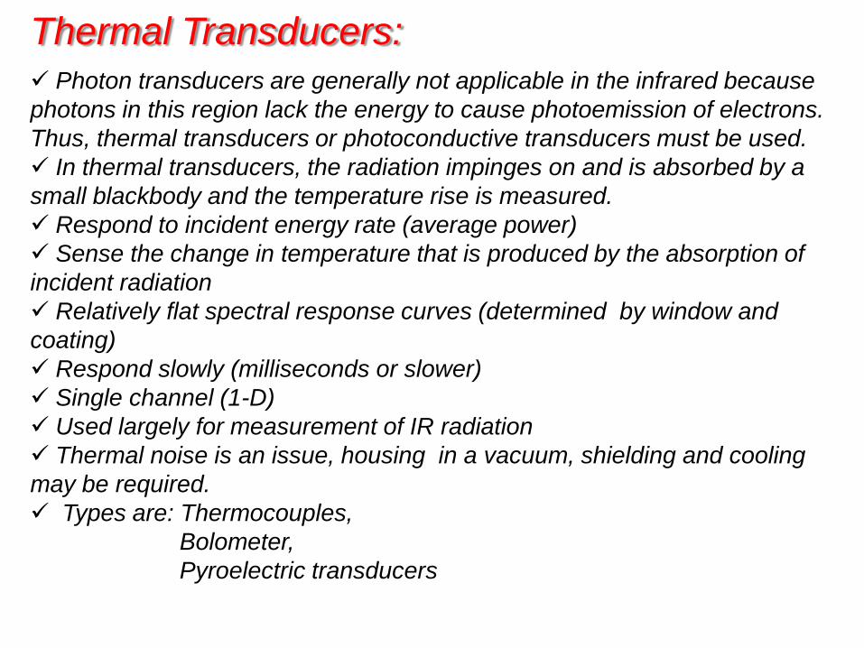
Thermal Transducers: Photon transducers are generally not applicable in the infrared because
photons in this region lack the energy to cause photoemission of electrons.
Thus, thermal transducers or photoconductive transducers must be used.
In thermal transducers, the radiation impinges on and is absorbed by a
small blackbody and the temperature rise is measured.
Respond to incident energy rate (average power)
Sense the change in temperature that is produced by the absorption of
incident radiation
Relatively flat spectral response curves (determined by window and
coating)
Respond slowly (milliseconds or slower)
Single channel (1-D)
Used largely for measurement of IR radiation
Thermal noise is an issue, housing in a vacuum, shielding and cooling
may be required.
Types are: Thermocouples,
Bolometer,
Pyroelectric transducers
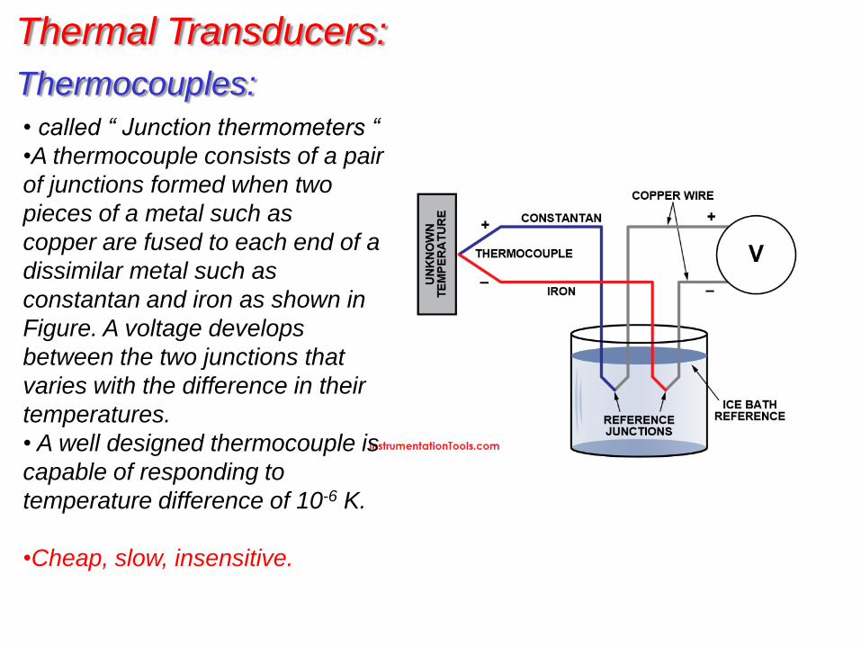
Thermal Transducers:
Thermocouples:
• called “ Junction thermometers “
•A thermocouple consists of a pair
of junctions formed when two
pieces of a metal such as
copper are fused to each end of a
dissimilar metal such as
constantan and iron as shown in
Figure. A voltage develops
between the two junctions that
varies with the difference in their
temperatures.
• A well designed thermocouple is
capable of responding to
temperature difference of 10-6 K.
•Cheap, slow, insensitive.
Thermal Transducers:
Bolometers: • called “ resistance thermometers “
• constructed of strips of metals, such as platinum or nickel or of a
semiconductor. Semiconductor bolometers are often called thermistors.
• These materials exhibit a relatively large change in resistance as a
function of temperature. The responsive element is kept small and
blackened to absorb radiant heat.
• Bolometers are not so extensively used as other infrared transducers for
the mid-infrared region. However, a germanium bolometer,
operated at 1.5 K, is nearly an ideal transducer for radiation in the 5 to 400
cm-1 (2000 to 25 m) range.
Highly sensitive
•Pyroelectric transducers are constructed from single crystalline wafers of
pyroelectric materials, which are insulators (dielectric materials) with very special
thermal and electrical properties.
•Triglycine sulfate (NH2CH2COOH)3,H2SO4,(usually deuterated or with a fraction of
the glycines replaced with alanine), is the most important pyroelectric material used
in the construction of infrared transducers.
•When an electric field is applied across any dielectric material, electric polarization
takes place whose magnitude is a function of the dielectric constant of the material.
For most dielectrics, this induced polarization rapidly decays to zero when the
external field is removed. Pyroelectric substances, in contrast, retain a strong
temperature-dependent polarization after removal of the field. Thus, by sandwiching
the pyroelectric crystal between two electrodes (one of which is infrared transparent)
a temperature-dependent capacitor is produced. Changing its temperature by
irradiating it with infrared radiation alters the charge distribution across the crystal,
which creates a measurable current in an external electrical circuit that connects the
two sides of the capacitor. The magnitude of this current is proportional to the
surface area of the crystal and to its rate of change of polarization with temperature.
•Pyroelectric transducers exhibit response times that are fast enough to allow them
to track the changes in the time-domain signal from an interferometer. For this
reason, most Fourier transform infrared spectrometers use this type of transducer.
Pyroelectric Transducers: Thermal Transducers:
Signal Processors and Readouts
The signal processor is ordinarily an electronic device that
amplifies the electrical signal from the transducer. In
addition, it may alter the signal from dc to ac (or the
reverse), change the phase of the signal, and filter it to
remove unwanted components. Furthermore, the signal
processor may be called upon to perform such
mathematical operations on the signal as differentiation,
integration, or conversion to a logarithm.