Embed Size (px)
Citation preview
Chapter 7
Energy Storage Elements
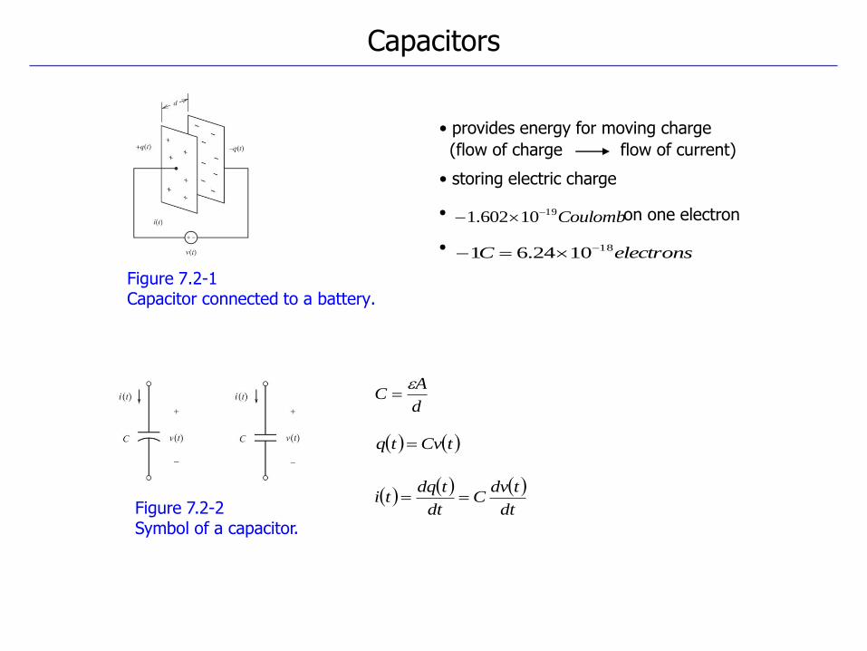
Figure 7.2-1 Capacitor connected to a battery.
Figure 7.2-2 Symbol of a capacitor.
Capacitors
tCvtq
d
AC
Coulomb1910602.1
electronsC 181024.61
• on one electron
•
• provides energy for moving charge
(flow of charge flow of current)
• storing electric charge
dt
tdvC
dt
tdqti
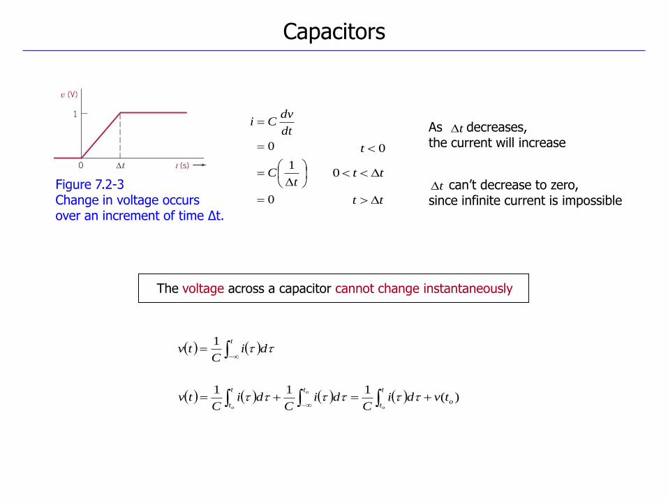
Figure 7.2-3 Change in voltage occurs over an increment of time Δt.
Capacitors
The voltage across a capacitor cannot change instantaneously
t
0
1
0
tC
dt
dvCi
0t
tt 0
tt
As decreases, the current will increase
can’t decrease to zero, since infinite current is impossible
t
diC
tv 1
t
)(111
o
t
t
tt
ttvdi
Cdi
Cdi
Ctv
o
o
o
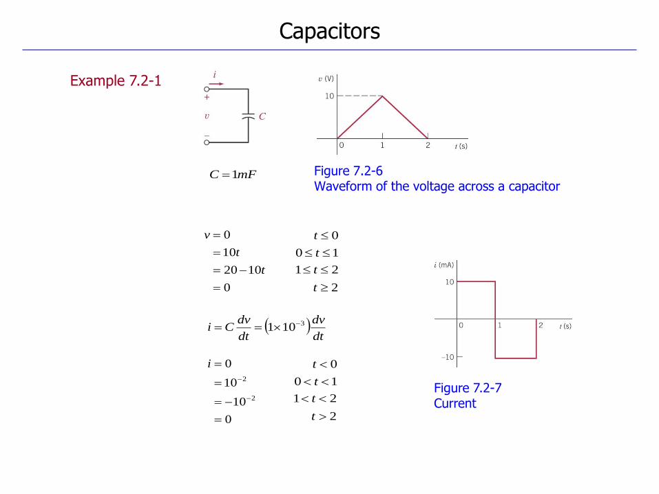
Figure 7.2-6 Waveform of the voltage across a capacitor
Example 7.2-1
Figure 7.2-7 Current
Capacitors
mFC 1
dt
dv
dt
dvCi 3101
0
1020
10
0
t
t
v
0
10
10
0
2
2
i
0t
10 t
2t
21 t
0t
10 t
2t
21 t
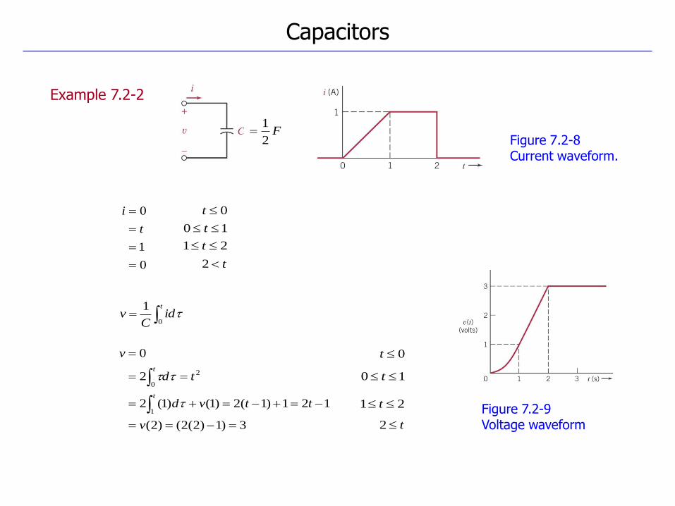
Figure 7.2-8 Current waveform.
Example 7.2-2
Figure 7.2-9 Voltage waveform
Capacitors
0
1
0
t
i 0t
10 t
t2
21 t
t
idC
v0
1
3)1)2(2()2(
121)1(2)1()1(2
2
0
1
2
0
v
ttvd
td
v
t
t
0t
10 t
t2
21 t
F2
1
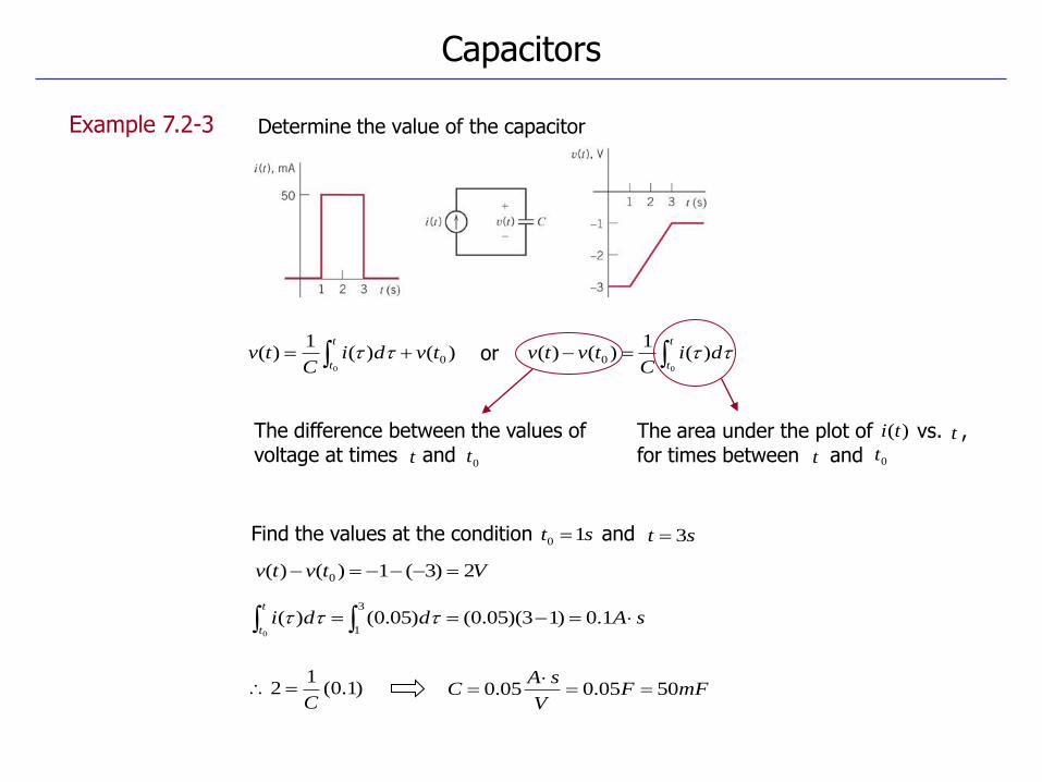
Example 7.2-3
Capacitors
Determine the value of the capacitor
0tt
The difference between the values of voltage at times and
)()(1
)( 00
tvdiC
tvt
t
t
tdi
Ctvtv
0
)(1
)()( 0 or
sAddit
t 1.0)13)(05.0()05.0()(
3
10
Vtvtv 2)3(1)()( 0
The area under the plot of vs. , for times between and 0tt
)(ti t
Find the values at the condition and st 10 st 3
)1.0(1
2C
mFFV
sAC 5005.005.0
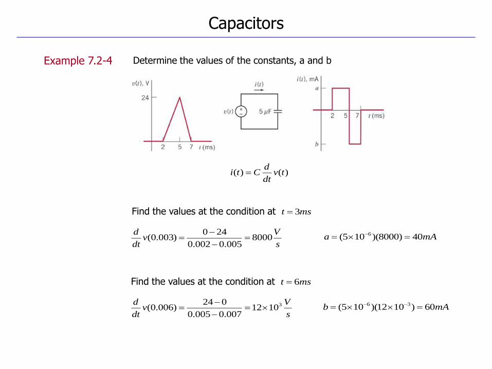
Example 7.2-4
Capacitors
Determine the values of the constants, a and b
)()( tvdt
dCti
Find the values at the condition at mst 3
mAa 40)8000)(105( 6
s
Vv
dt
d8000
005.0002.0
240)003.0(
mAb 60)1012)(105( 36
s
Vv
dt
d 31012007.0005.0
024)006.0(
Find the values at the condition at mst 6
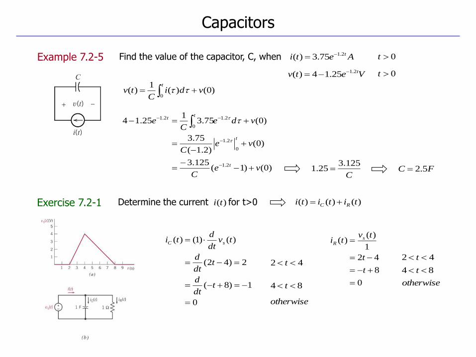
Exercise 7.2-1
Example 7.2-5
Capacitors
Determine the current for t>0 )(ti
t
vdiC
tv0
)0()(1
)(
)0()1(125.3
)0()2.1(
75.3
)0(75.31
25.14
2.1
0
2.1
2.1
0
2.1
veC
veC
vdeC
e
t
t
tt
Find the value of the capacitor, C, when
Vetv t2.125.14)(
Aeti t2.175.3)( 0t
0t
C
125.325.1 FC 5.2
)()()( tititi RC
0
1)8(
2)42(
)()1()(
tdt
d
tdt
d
tvdt
dti sC
0
8
42
1
)()(
t
t
tvti s
R
42 t
84 t
otherwise
42 t
84 t
otherwise
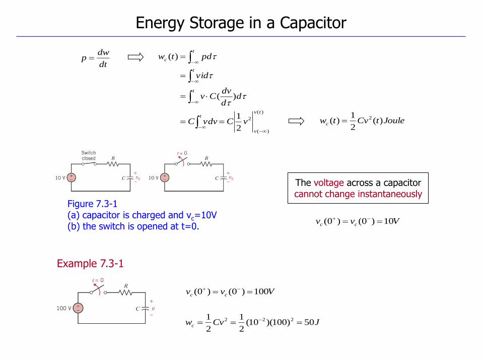
Figure 7.3-1 (a) capacitor is charged and vc=10V (b) the switch is opened at t=0.
Example 7.3-1
Energy Storage in a Capacitor
dt
dwp
Vvv cc 10)0()0(
)(
)(
2
2
1
)(
)(
tv
v
t
t
t
t
c
vCvdvC
dd
dvCv
vid
pdtw
JouletCvtwc )(2
1)( 2
The voltage across a capacitor cannot change instantaneously
Vvv cc 100)0()0(
JCvwc 50)100)(10(2
1
2
1 222
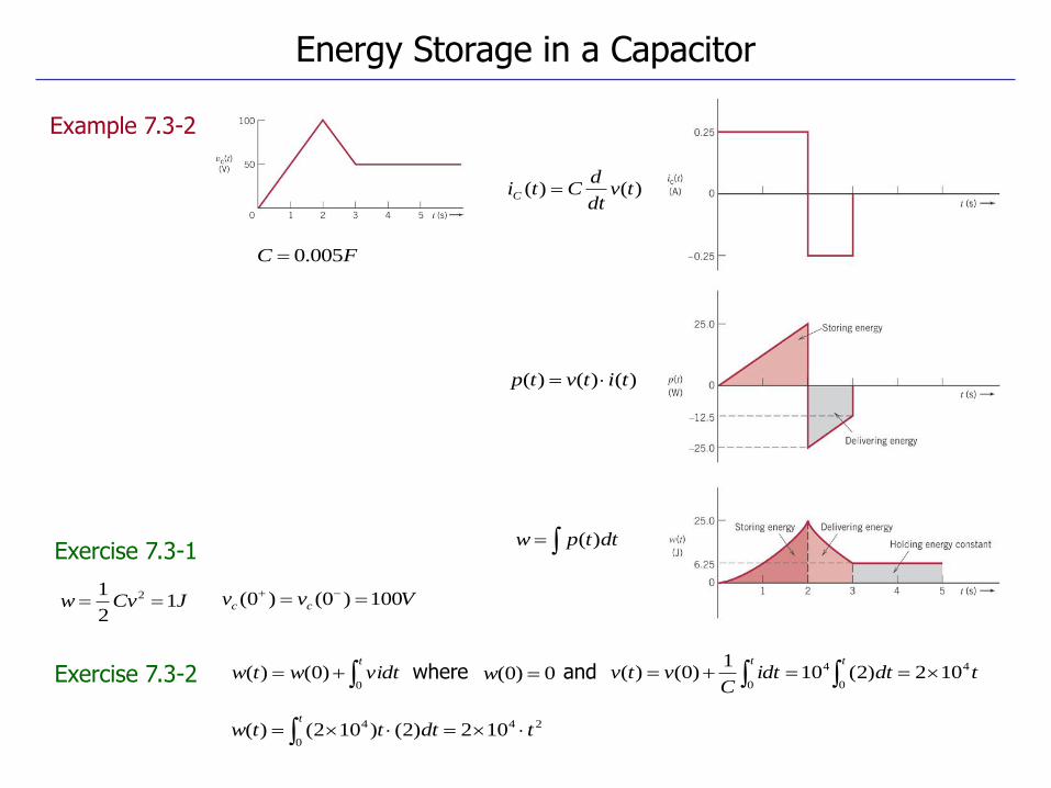
Example 7.3-2
Exercise 7.3-1
Exercise 7.3-2
Energy Storage in a Capacitor
FC 005.0
)()( tvdt
dCtiC
)()()( titvtp
dttpw )(
t
vidtwtw0
)0()(
JCvw 12
1 2 Vvv cc 100)0()0(
24
0
4 102)2()102()( tdtttwt
0)0( wwhere and tdtidtC
vtvtt
4
0
4
0102)2(10
1)0()(
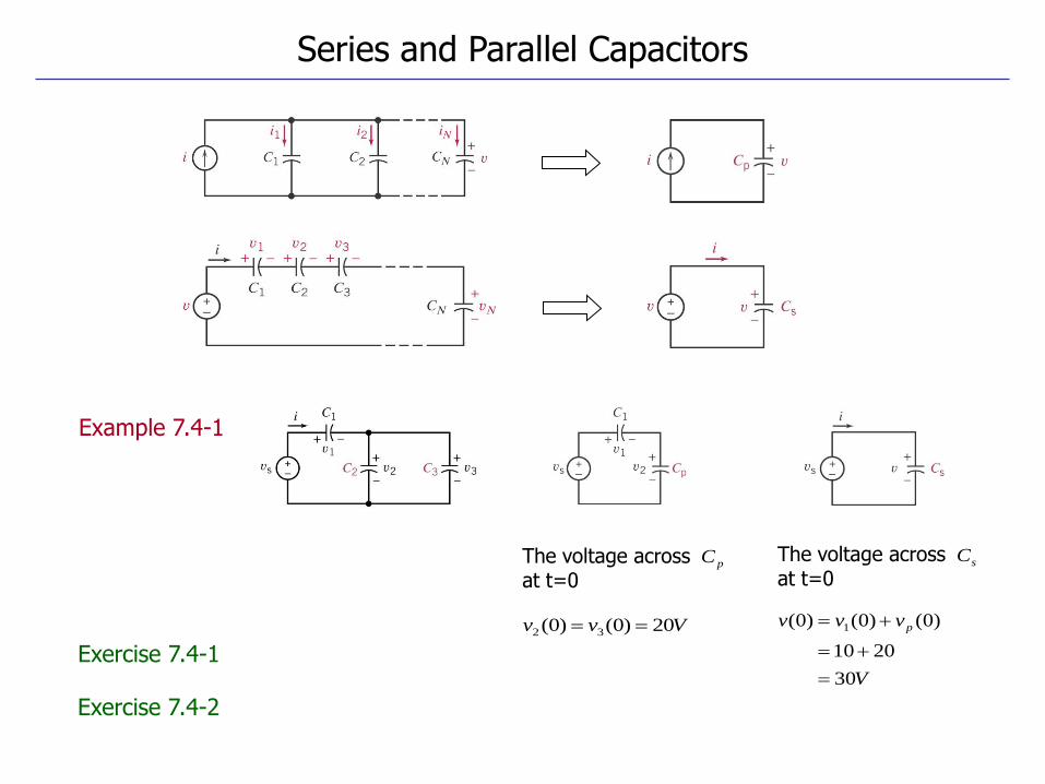
Series and Parallel Capacitors
Example 7.4-1
Exercise 7.4-1
Exercise 7.4-2
Vvv 20)0()0( 32
pCThe voltage across at t=0
sCThe voltage across at t=0
V
vvv p
30
2010
)0()0()0( 1
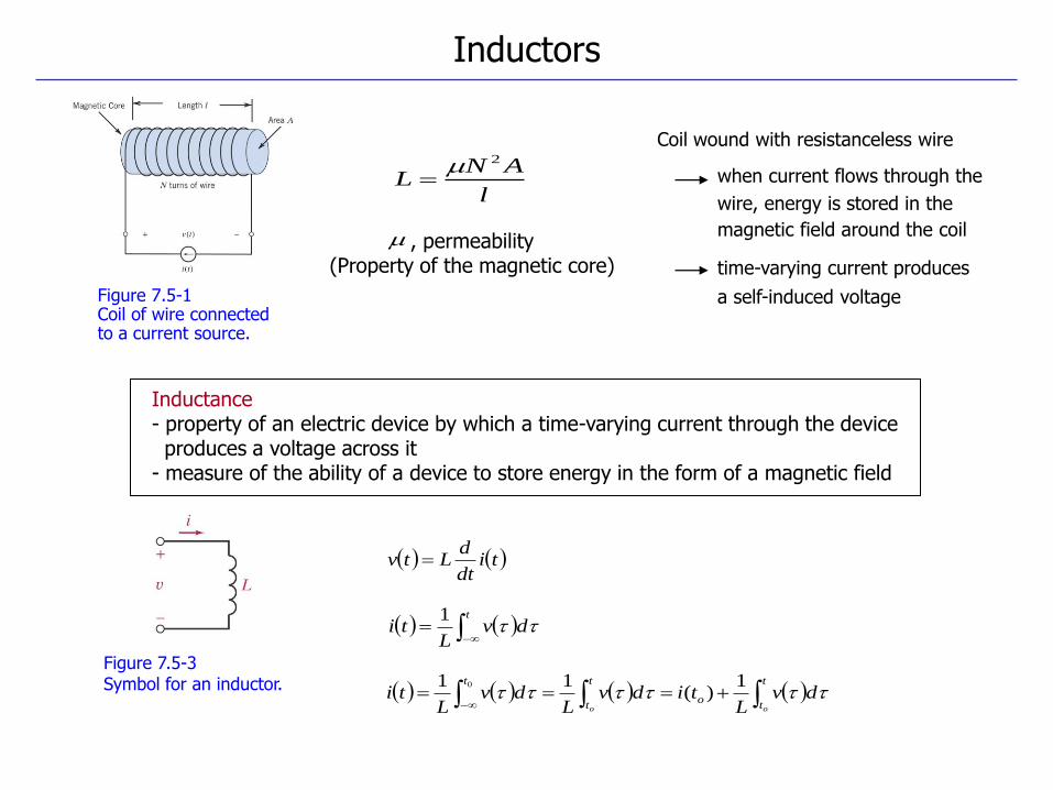
Figure 7.5-1 Coil of wire connected to a current source.
Figure 7.5-3 Symbol for an inductor.
Inductors
Inductance - property of an electric device by which a time-varying current through the device produces a voltage across it - measure of the ability of a device to store energy in the form of a magnetic field
Coil wound with resistanceless wire
when current flows through the
wire, energy is stored in the
magnetic field around the coil
time-varying current produces
a self-induced voltage
l
ANL
2
, permeability (Property of the magnetic core)
tidt
dLtv
t
to
t
t
t
oo
dvL
tidvL
dvL
ti 1
)(11 0
t
dvL
ti 1
Inductors
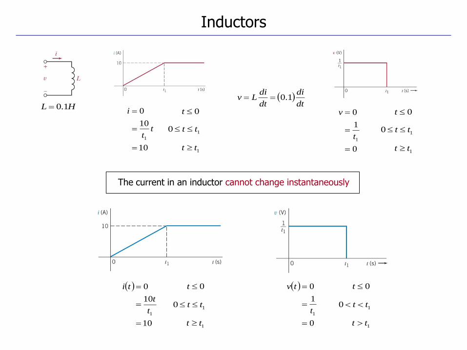
HL 1.0
dt
di
dt
diLv 1.0
0
1
0
1
t
v
10
10
0
1
tt
i 0t
10 tt
1tt
0t
10 tt
1tt
The current in an inductor cannot change instantaneously
10
10
0
1
t
t
ti 0t
10 tt
1tt
0
1
0
1
t
tv 0t
10 tt
1tt
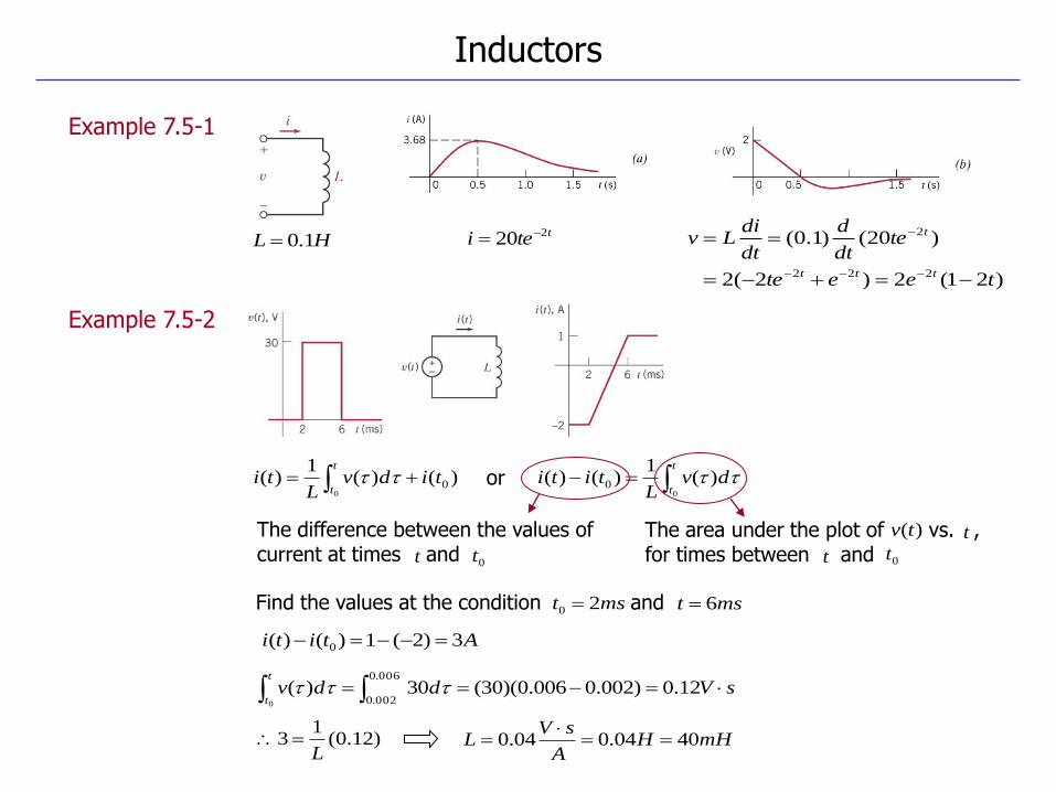
Example 7.5-1
Example 7.5-2
HL 1.0ttei 220
)21(2)2(2
)20()1.0(
222
2
teete
tedt
d
dt
diLv
ttt
t
0tt
The difference between the values of current at times and
The area under the plot of vs. , for times between and 0tt
)(tv t
Find the values at the condition and mst 20 mst 6
)()(1
)( 00
tidvL
tit
t
t
tdv
Ltiti
0
)(1
)()( 0 or
sVddvt
t 12.0)002.0006.0)(30(30)(
006.0
002.00
Atiti 3)2(1)()( 0
)12.0(1
3L
mHHA
sVL 4004.004.0
Inductors
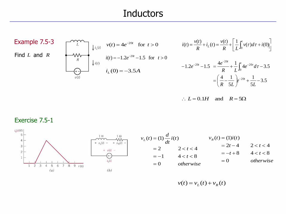
Exercise 7.5-1
Example 7.5-3
Find and RL0for 5.12.1)( 20 teti t
AiL 5.3)0(
0for 4)( 20 tetv t
5 and 1.0 RHL
t
L idvLR
tvti
R
tvti
0)0()(
1)()(
)()(
5.35
1
5
14
5.3414
5.12.1
20
0
2020
20
Le
LR
deLR
ee
t
tt
t
otherwise
t
t
tidt
dtvL
0
84 1
42 2
)()1()(
)()()( tvtvtv RL
otherwise
tt
tt
titvR
0
84 8
42 42
)()1()(
Inductors
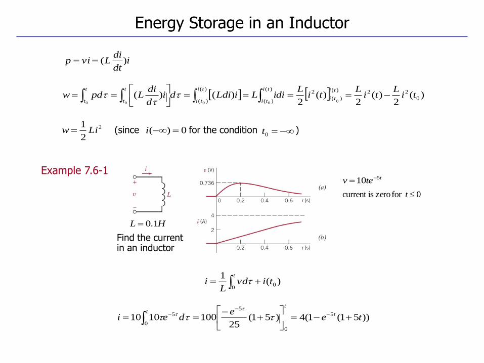
Example 7.6-1
idt
diLvip )(
)(2
)(2
)(2
)()( 0
22)(
)(
2)(
)(
)(
)( 00000
tiL
tiL
tiL
idiLiLdidid
diLpdw
ti
ti
ti
ti
ti
ti
t
t
t
t
Energy Storage in an Inductor
2
2
1Liw 0)( i 0t(since for the condition )
HL 1.0
)(1
00
tivdL
it
0for zero iscurrent t
ttev 510
Find the current in an inductor
))51(1(4)51(25
1001010 5
0
5
0
5 tee
dei t
tt
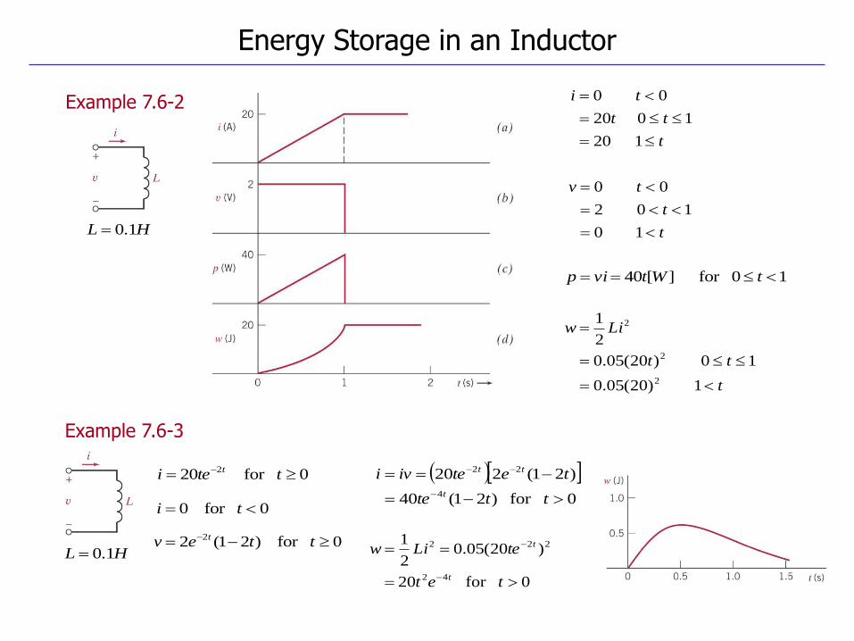
Example 7.6-2
Example 7.6-3
Energy Storage in an Inductor
t
tt
ti
1 20
10 20
0 0
HL 1.0
10for ][40 tWtvip
t
t
tv
1 0
10 2
0 0
t
tt
Liw
1 )20(05.0
10 )20(05.0
2
1
2
2
2
HL 1.0
0for 20 2 ttei t
0for )21(2 2 ttev t
0for 0 ti
0for )21(40
)21(220
4
22
ttte
teteivi
t
tt
0for 20
)20(05.02
1
42
222
tet
teLiw
t
t
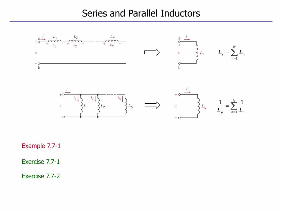
Series and Parallel Inductors
Example 7.7-1
Exercise 7.7-1
Exercise 7.7-2
N
n
ns LL1
N
n np LL 1
11
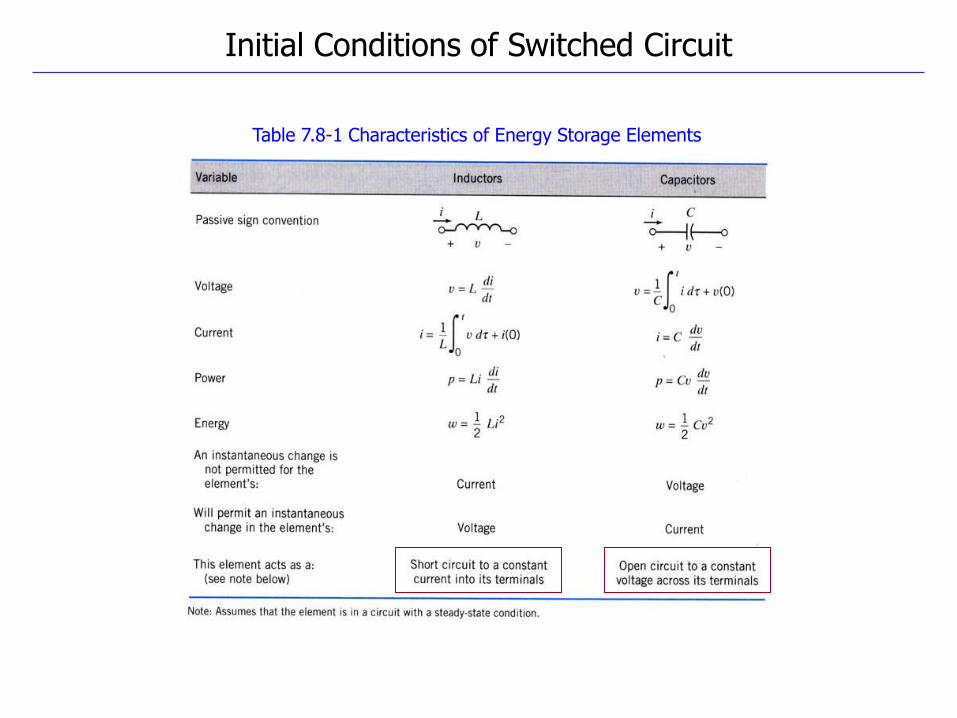
Initial Conditions of Switched Circuit
Table 7.8-1 Characteristics of Energy Storage Elements
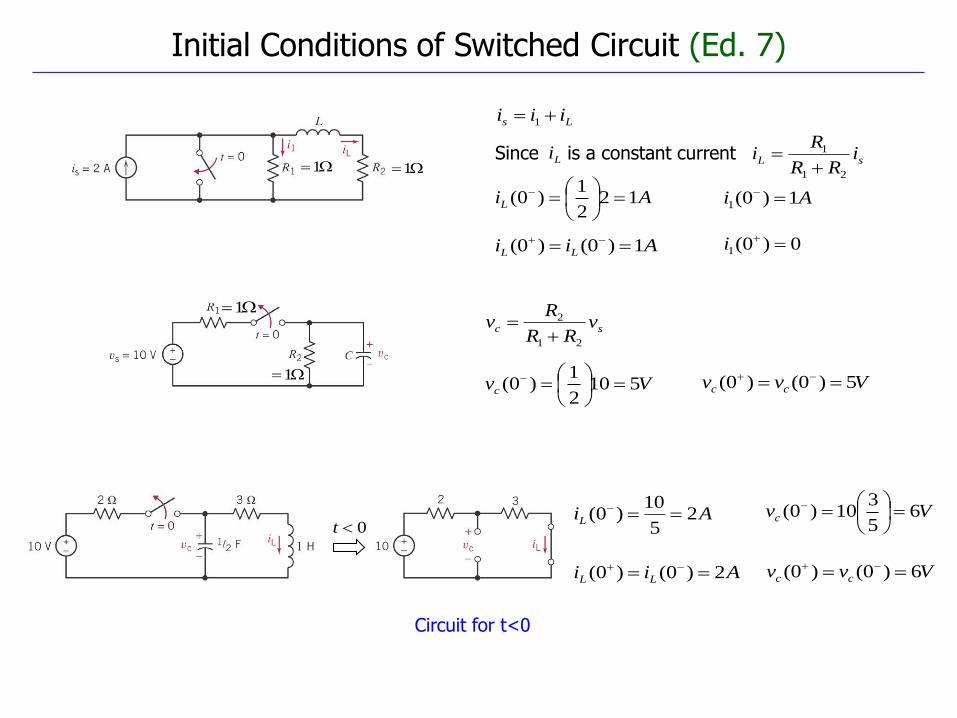
Circuit for t<0
Initial Conditions of Switched Circuit (Ed. 7)
Ls iii 1
11sL i
RR
Ri
21
1
LiSince is a constant current
AiL 122
1)0(
Aii LL 1)0()0(
Ai 1)0(1
0)0(1 i
1
1
sc vRR
Rv
21
2
Vvc 5102
1)0(
Vvv cc 5)0()0(
AiL 25
10)0( Vvc 6
5
310)0(
Aii LL 2)0()0( Vvv cc 6)0()0(
0t
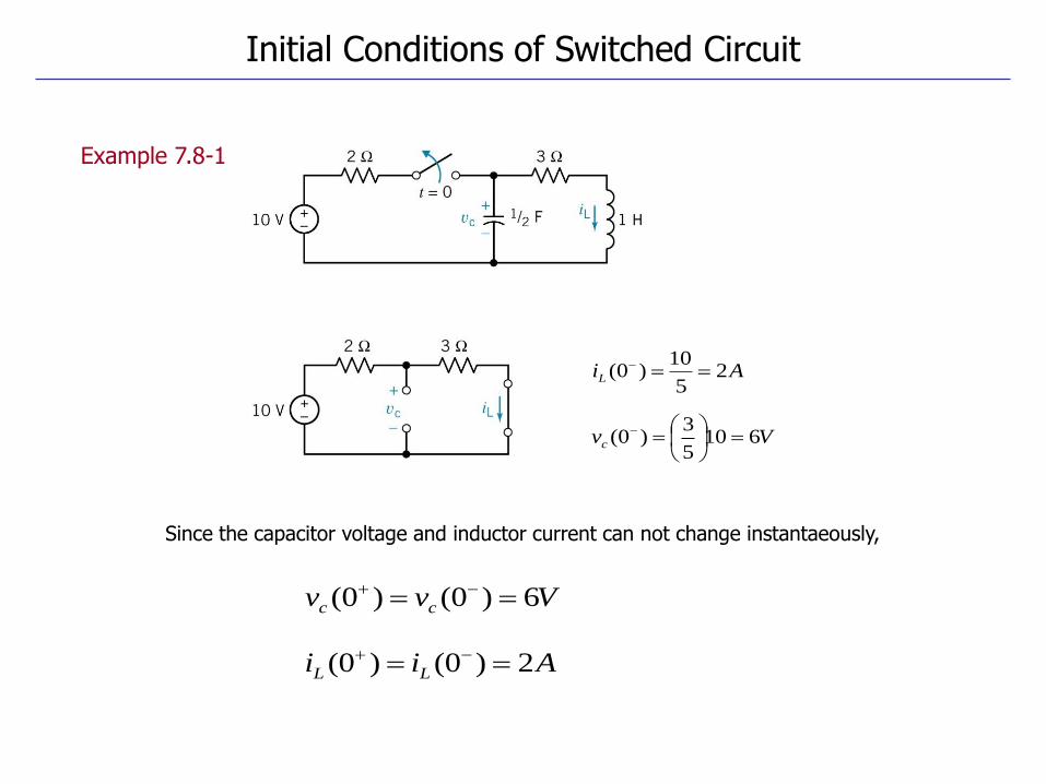
Example 7.8-1
Initial Conditions of Switched Circuit
AiL 25
10)0(
Vvc 6105
3)0(
Since the capacitor voltage and inductor current can not change instantaeously,
Aii LL 2)0()0(
Vvv cc 6)0()0(
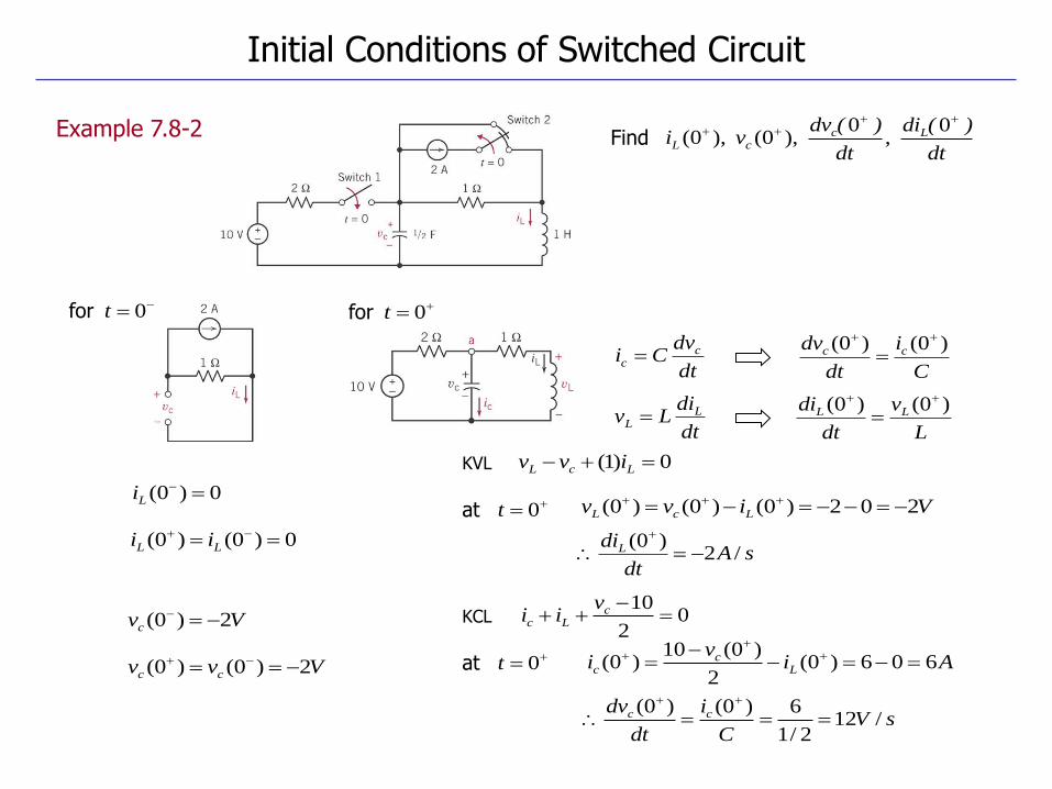
Example 7.8-2
Initial Conditions of Switched Circuit
Find dt
)(di
dt
)(dvvi Lc
cL
0
,0
),0( ),0(
0tfor
dt
dvCi c
c
0)0(
Li
Vvc 2)0(
0)0()0(
LL ii
Vvv cc 2)0()0(
0tfor
C
i
dt
dv cc )0()0(
dt
diLv L
L L
v
dt
di LL )0()0(
0)1( LcL ivvKVL
0tat
sAdt
diL /2)0(
Vivv LcL 202)0()0()0(
02
10
c
Lc
viiKCL
0tat
sVC
i
dt
dv cc /122/1
6)0()0(
Aiv
i Lc
c 606)0(2
)0(10)0(
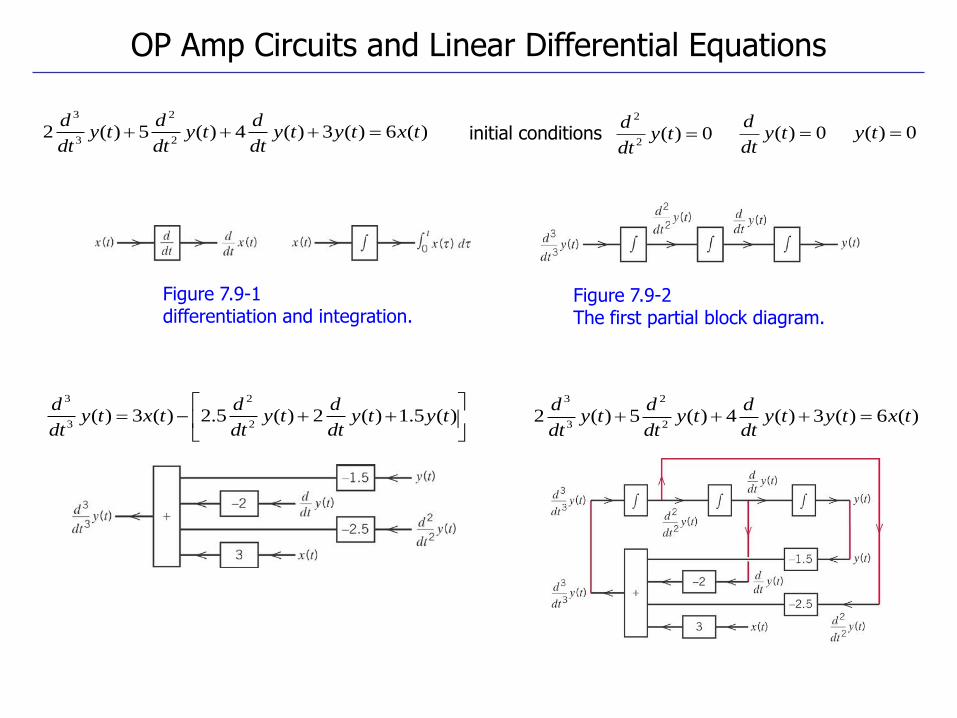
Figure 7.9-2 The first partial block diagram.
Figure 7.9-1 differentiation and integration.
OP Amp Circuits and Linear Differential Equations
)(6)(3)(4)(5)(22
2
3
3
txtytydt
dty
dt
dty
dt
d initial conditions 0)( ty
dt
d0)(
2
2
tydt
d0)( ty
)(5.1)(2)(5.2)(3)(
2
2
3
3
tytydt
dty
dt
dtxty
dt
d)(6)(3)(4)(5)(2
2
2
3
3
txtytydt
dty
dt
dty
dt
d

Figure 7.9-6 The integrator.
OP Amp Circuits and Linear Differential Equations
)(0)()()()( 21 txtxtvtvtvR
0)0( then ,0)0( Cvy
R
tx
R
tvti R
R
)()()(
R
txtiti RC
)()()(
)()(0)()()( 32 tytytvtvtvC
)0()(1
)(0
C
t
CC vdiC
tv
dxRC
dR
x
Cdi
Ctv
ttt
CC 000
)(1)(1
)(1
)(
dxRC
tyt
0
)(1
)(
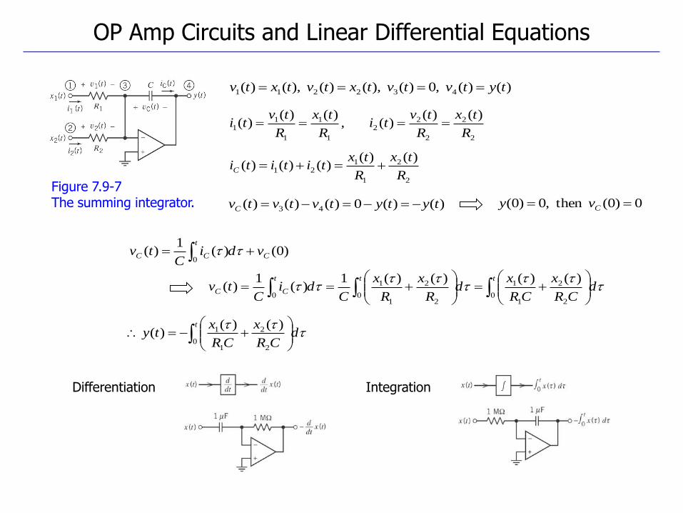
Figure 7.9-7 The summing integrator.
OP Amp Circuits and Linear Differential Equations
Differentiation Integration
)()( ,0)( ),()( ),()( 432211 tytvtvtxtvtxtv
0)0( then ,0)0( Cvy
2
2
2
22
1
1
1
11
)()()( ,
)()()(
R
tx
R
tvti
R
tx
R
tvti
2
2
1
121
)()()()()(
R
tx
R
txtititiC
)()(0)()()( 43 tytytvtvtvC
)0()(1
)(0
C
t
CC vdiC
tv
dCR
x
CR
xd
R
x
R
x
Cdi
Ctv
ttt
CC
02
2
1
1
02
2
1
1
0
)()()()(1)(
1)(
dCR
x
CR
xty
t
02
2
1
1 )()()(
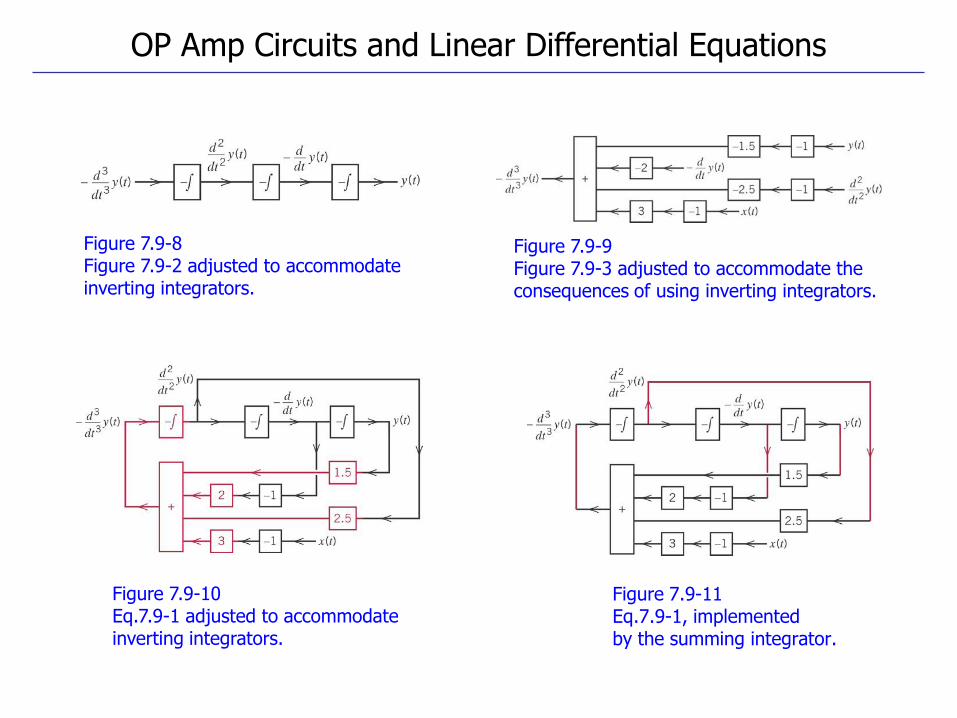
Figure 7.9-11 Eq.7.9-1, implemented by the summing integrator.
Figure 7.9-10 Eq.7.9-1 adjusted to accommodate inverting integrators.
Figure 7.9-8 Figure 7.9-2 adjusted to accommodate inverting integrators.
Figure 7.9-9 Figure 7.9-3 adjusted to accommodate the consequences of using inverting integrators.
OP Amp Circuits and Linear Differential Equations
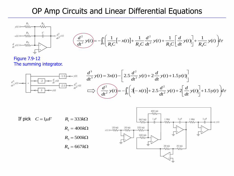
Figure 7.9-12 The summing integrator.
OP Amp Circuits and Linear Differential Equations
)(5.1)(2)(5.2)(3)(
2
2
3
3
tytydt
dty
dt
dtxty
dt
d
dtyCR
tydt
d
CRty
dt
d
CRtx
CRty
dt
d t
043
2
2
21
2
2
)(1
)(1
)(1
)(1
)(
t
dtytydt
dty
dt
dtxty
dt
d
0 2
2
2
2
)(5.1)(2)(5.2)(3)(
If pick FC 1 kR 3331
kR 4002
kR 6674
kR 5003
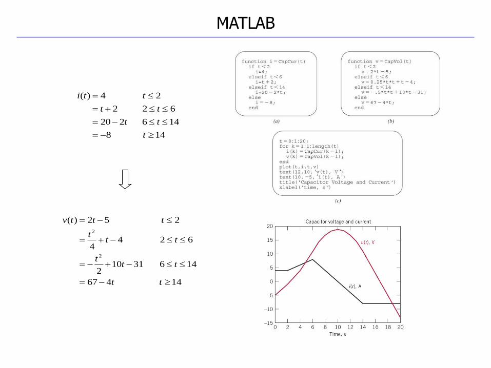
MATLAB
14 8
146 220
62 2
2 4)(
t
tt
tt
tti
14 467
146 31102
62 44
2 52)(
2
2
tt
ttt
ttt
tttv
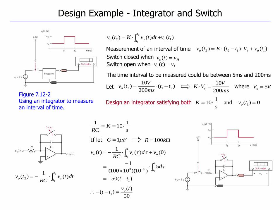
Figure 7.12-2 Using an integrator to measure an interval of time.
Design Example - Integrator and Switch
Design an integrator satisfying both
)()()( 12
2
1
tvdttvKtv o
t
tso
0)( and 1
10 1 tvs
K o
Measurement of an interval of time )()()( 1122 tvVttKtv oso
Hc vtv )(Switch closed when
Switch open when Lc vtv )(
The time interval to be measured could be between 5ms and 200ms
Let )(200
10)( 212 tt
ms
Vtvo
ms
VVK s
200
10 where VVs 5
2
1
)(1
)( 2
t
tso dttv
RCtv
sK
RC
110
1
If let FC 1 kR 100
)(50
5)10)(10100(
1
)0()(1
)(
1
631
1
tt
d
vdvRC
tv
t
t
o
t
tso
50
)()( 1
tvtt o
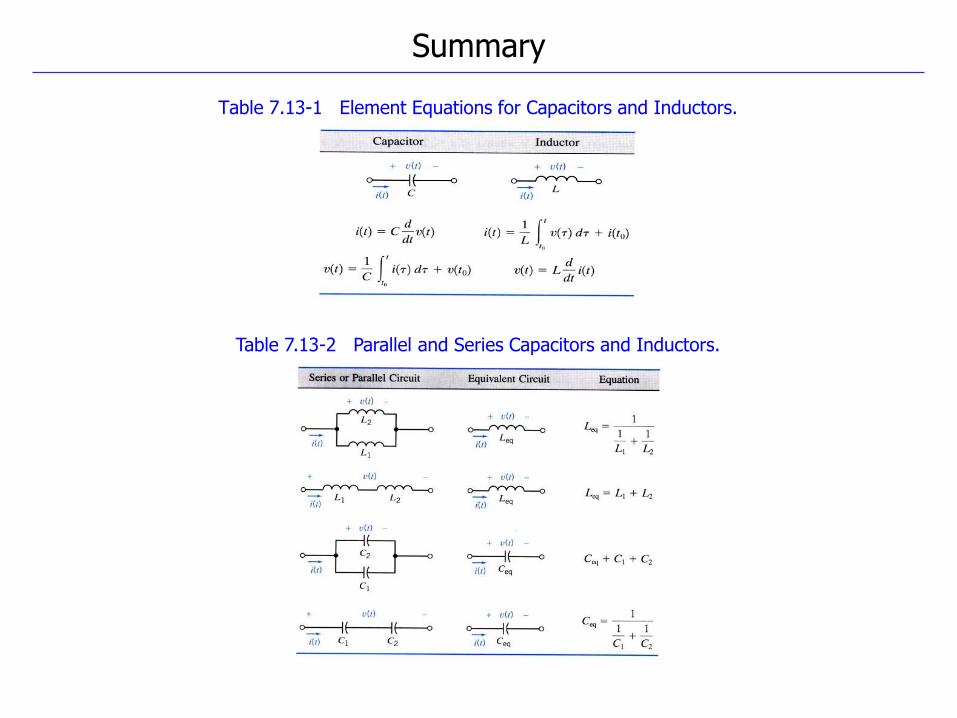
Table 7.13-1 Element Equations for Capacitors and Inductors.
Table 7.13-2 Parallel and Series Capacitors and Inductors.
Summary
Problems P7.2-5 / P7.2-11 / P7.2-15 / P7.3-3 /
P7.5-4 / P7.5-10 / P7.5-14 / P7.6-3 /
P7.7-9 / P7.8-3 / P7.8-10
Homework #7