Embed Size (px)
Citation preview

Manual Road Drainage Chapter 7: Environmental Consideration and Design July 2015

Road Drainage Manual, Transport and Main Roads, July 2015
Copyright
http://creativecommons.org/licenses/by/3.0/au/
© State of Queensland (Department of Transport and Main Roads) 2015
Feedback: Please send your feedback regarding this document to: [email protected]

Contents
7 Environmental consideration and design ...................................................................................1
7.1 Introduction ..................................................................................................................................... 1
7.2 Legislative requirements and general environmental duty ............................................................. 1
7.3 Environmental values and water quality objectives ........................................................................ 1
7.4 Pollution control: water quality ........................................................................................................ 1 7.4.1 Establishing pollution control requirements ....................................................................2
7.5 Water quality treatment devices and design guidelines ............................................................... 11 7.5.1 Filter strips ................................................................................................................... 11 7.5.2 Grassed swales ........................................................................................................... 13 7.5.3 Trash racks .................................................................................................................. 15 7.5.4 Proprietary devices ...................................................................................................... 17 7.5.5 Constructed wetlands .................................................................................................. 18 7.5.6 Buffer zones ................................................................................................................ 21 7.5.7 Water quality ponds ..................................................................................................... 22
7.6 Fauna passage ............................................................................................................................. 23 7.6.1 Identifying fauna passage criteria ................................................................................ 23 7.6.2 Identify terrestrial and aquatic fauna pathways ........................................................... 24 7.6.3 Identify the species group ........................................................................................... 24 7.6.4 Consult with the relevant authority .............................................................................. 24 7.6.5 Identify criteria affecting drainage design .................................................................... 25
Tables
Table 7.4.1.2– Design objectives for management of stormwater quality .............................................. 3
Table 7.4.1.6 – Design elements associated with treatment devices ..................................................... 8
Table 7.4.1.7 – Pollutant removal performance of various treatment devices ...................................... 10
Table 7.6.4 – Commonly triggered legislation for the protection of fauna ............................................. 24
Figures
Figure 7.5.1.1 – Grass filter strip ........................................................................................................... 11
Figure 7.5.3.1(a) – Trash rack ............................................................................................................... 15
Figure 7.5.3.1(b) – Trash rack and pollutants ....................................................................................... 16
Road Drainage Manual, Transport and Main Roads, July 2015 i

Chapter 7: Environmental Consideration and Design
7 Environmental consideration and design
7.1 Introduction
Road infrastructure environmental issues should be identified and assessed throughout the road planning and design process. Project-specific environmental assessment provides information about the condition of the existing environment, the proposed project area, associated environmental impacts of the proposal and the identification of any opportunities for environmental management.
In this chapter, an approach to acknowledging and addressing the relationship between site drainage and requirements for water pollution control, design of water pollution control measures and fauna passages are examined. Basic principles and design criteria for the mitigation of these environmental issues will also be discussed.
This chapter relates to the ongoing potential impacts from the operation of roads that can be mitigated through good drainage design. Construction impacts are not discussed in this chapter but managed through environmental management plans and erosion and sediment control. Design aspects of erosion and sediment control issues during construction are discussed in Chapter 13.
This chapter links in with Chapter 12 on basins. Understanding pollution sources, transport mechanisms and removal techniques in this chapter will assist in applying the design principles and practices of this chapter and that of Chapter 12.
7.2 Legislative requirements and general environmental duty
The Environmental Protection Act 1994 places an obligation upon all persons in Queensland who are carrying out activities which may cause environmental harm. Under this Act, the department and all persons working for the department must adopt all reasonable and practical measures to prevent or minimise environmental harm. This is called the general environmental duty.
Other general requirements on permanent water quality are discussed further in Section 7.3. General requirements regarding fauna are detailed in Section 7.6.
Depending on the location and scope of work, there may also be project-specific legislative requirements. Project-specific legislative requirements with regard to design requirements will be outlined in the project environmental assessment.
For up-to-date information on general legislative requirements, contact your local departmental environmental officer and/or refer to the department’s Environmental Legislation Register.
7.3 Environmental values and water quality objectives
The Queensland Government, through the Environmental Protection (Water) Policy 2009, details environmental values that it is seeking to protect and enhance for the majority of waterbodies within Queensland. Specific water quality objectives are then set for these values.
The environmental values and the water quality objectives for waterbodies that the road is draining into can therefore provide an indication of the level of treatment that should be incorporated into road drainage design.
7.4 Pollution control: water quality
A key environmental consideration related to drainage (via stormwater, site water runoff, rainfall, litter and spills) is pollutant export and its resulting impact on water quality. Pollutants contained in runoff
Road Drainage Manual, Transport and Main Roads, July 2015 1

Chapter 7: Environmental Consideration and Design
and drainage from road corridors have the potential to adversely affect the water quality and aquatic biota of receiving waters with short- or long-term impacts.
For any given project, the significance and impact of pollutant export will depend upon:
• the relative sensitivity of the receiving environment
• traffic type and volume
• road project infrastructure type and form (such as off-ramp, traffic lights, bend in road, steep hill, and so on)
• climatic factors experienced in the locality.
Therefore, pollution control techniques must be established and implemented according to many factors, including the type, source, concentration of pollutant export and the risk of harm the pollutant may have on the receiving environment.
7.4.1 Establishing pollution control requirements
When identifying the need for pollution control, the following steps should be completed:
a) Determine management objective (Section 7.4.1.1)
b) Determine water quality design criteria (Section 7.4.1.2)
c) Identify pollutant sources and estimation of pollutant loads (Section 7.4.1.3)
d) Identify pollutant transport processes (Section 7.4.1.4)
e) Identify pollutant removal processes (Section 7.4.1.5)
f) Assess potential pollutant control devices (Section 7.4.1.6)
g) Calculate potential pollutant removal (Section 7.4.1.7)
h) Implement treatments (Section 7.4.1.8)
i) Evaluate the working efficacy of pollutant removal processes and review if necessary (Section 7.4.1.9).
7.4.1.1 Determine management objective
The project’s management objective in relation to water quality should be determined based on a number of elements:
• Scale and scope of project
− Low: minimal drainage works involved in scope of works, gravel roads
− Medium: projects involve some drainage design, drainage already existing, some ability to make minor amendments to existing drainage and/or retrofit water quality measures
− High: greenfield projects, major opportunities to optimise drainage design and achieve water quality objectives
• Quality of receiving environment.
Road Drainage Manual, Transport and Main Roads, July 2015 2

Chapter 7: Environmental Consideration and Design
7.4.1.2 Determine water quality design criteria
Design criteria for water quality may be set as:
1. reduction in mean annual load compared to unmitigated development (%)
2. concentration of various pollutants in runoff.
Reduction in mean annual load
Stormwater policies and guidelines for water sensitive urban design are increasingly using reduction in annual pollutant load as the design criteria.
In Queensland, the design objectives in Table 7.4.1.2 have been set for all low erosion risk Environmentally Relevant Activities (through Stormwater Guideline – Environmentally Relevant Activities, Department of Environment and Heritage Protection, 2014) and for development in urban areas subject to local planning schemes (through the State Planning Policy).
This approach is recommended to be adopted for road design.
Table 7.4.1.2– Design objectives for management of stormwater quality
Region Minimum reductions in mean annual loads from unmitigated development (%)
Notes
Total suspended solids (TSS)
Total phosphorus
(TP)
Total nitrogen
(TN)
Gross pollutants
Cape York / Far North Queensland
80 60 45 90 TSS – DEHP has 75% for Eastern and Northern Cape York TP – DEHP has 65% for SW and Central South Cape York TN – DEHP has 35% reduction for (Eastern Cape York) and 40 elsewhere
Wet Tropics 80 60 (DSDIP) 65 (DEHP)
40 90
Dry Tropics 80 60 (DSDIP) 65 (DEHP)
40 90 Townsville City Council has adopted 65% for TP
Central Queensland (north)
75 60 35* (DEHP)
40 (DSDIP)
90
Central Queensland (south)
85 60 (DSDIP) 70 (DEHP)
45 90
South East Queensland
80 60 45 90
Road Drainage Manual, Transport and Main Roads, July 2015 3

Chapter 7: Environmental Consideration and Design
Region Minimum reductions in mean annual loads from unmitigated development (%)
Notes
Total suspended solids (TSS)
Total phosphorus
(TP)
Total nitrogen
(TN)
Gross pollutants
Western Queensland
85 60 (DSDIP) 70 (DEHP)
45 90
From:
• Stormwater Guideline – Environmentally Relevant Activities (Department of Environment and Heritage Protection, 2014)
• State Planning Policy (Department of State Development, Infrastructure and Planning, 2014)
Note: Within the State Planning Policy, these stormwater management design objectives relate only to urban centres.
Runoff pollutant concentration
Chapter 7 of Engineers Australia’s Australian Runoff Quality outlines a methodology for estimating permissible concentrations of runoff to meet receiving water quality guideline levels such as those within the Environmental Protection (Water) Policy 2009. This methodology involves the development of models that include equations for water body hydrodynamics and associated physico-chemical and biological processes.
7.4.1.3 Identify pollutant sources and estimation of pollutant loads
Section 3.4.2 of Austroads’ Guide to Road Design – Part 5 provides an overview of potential pollutants within road runoff. Increased alkalinity of stormwater from concrete systems is a relatively new issue with potential impact on biodiversity being investigated (Wright et al, 2010).
The pollutant loads associated with corridor drainage will be a sum of the direct pollutant concentrates from the road (such as heavy metals from brakes, oils from vehicles) and indirect impacts from catchment areas draining to corridor (such as nutrient runoff from agriculture or litter from urban areas).
Road runoff pollutant loads can be estimated by:
• analysis of data from a representative storm-event monitoring program combined with simple computations
• an appropriate water quality model.
The method selected will depend on the management objective, water quality criteria chosen and data availability. Average long-term pollutant loads can be estimated from historic rainfall data, baseline monitoring and from simple information about the catchment and road corridor, or qualitative understandings of catchment and management techniques.
Event Mean Concentrations
Event Mean Concentration (EMC) can be estimated by monitoring mean pollutant concentration and discharge over a storm event. EMC within one catchment can, however, differ significantly from storm to storm. The EMC depends on many catchment and climate characteristics and can vary in magnitude between catchments.
Road Drainage Manual, Transport and Main Roads, July 2015 4

Chapter 7: Environmental Consideration and Design
Therefore, a good event monitoring program is essential where accurate estimates of pollutant loads are required. Significant errors in estimating long-term pollutant loads can result without monitoring programs. Typical errors in estimating long term pollutant loads are as follows:
• no monitoring – 100 to more than 1000 per cent
• some periodic monitoring – 50 to more than 500 per cent
• detailed event monitoring – 20 to 100 per cent.
Pollutant loads
Simple computations can be used as a guide to calculate approximate estimates of pollutant loads. This can be useful when assessing potential pollutant loads in rainfall volumes.
The average long-term pollutant load of an area can be estimated using the following formula:
Pollutant load = runoff x EMC where EMC = Event Mean Concentration
Water quality modelling
Computer models may be used to estimate runoff quantity and quality from a road corridor to provide estimates for:
• characterising peak, mean and average annual pollutant loads
• determining seasonal and spatial characteristics.
A number of water quality and stormwater system models exist, which are designed for use by engineers, managers, planners and other staff from private to public organisations.
A commonly used catchment model used to assist water quality management is the Model for Urban Stormwater Improvement Conceptualisation or ‘MUSIC’ (Wong et al 2002). MUSIC modelling is a decision support tool that can assist in the planning of stormwater quality management strategies.
MUSIC allows the user to determine the likely stormwater quality resulting from specific catchments, predict specific stormwater treatment device performance and create subsequent management plans and evaluate their success.
MUSIC can operate over a range of spatial and temporal scales. It can be used with several other models, such as models used for soils, hydrology, rainfall, operation of culverts, and so on (Wong et al 2002 and eWater 2008).
7.4.1.4 Identify pollutant transport processes
The determination of additional design criteria to enhance or maintain the downstream water quality will require the knowledge of relevant pollutant transport mechanisms.
Pollutant runoff from a roadway will be generally transported by the roadway drainage infrastructure and will concentrate in gutters, pipes and channels. The pollutants associated with the stormwater runoff will be transported as coarse or bottom sediments, suspended (fine) particles or in solution. The rate of pollutant transport is dependent on pollutant size, water velocity, depth and the degree of turbulence.
Fine particulates and dissolved pollutants (such as heavy metals) can become attached to sediments or flocculate to form larger particles. Most of the pollutants in sediments are found attached to smaller particles owing to their greater surface area relative to larger particles. Pollutants attached to fine
Road Drainage Manual, Transport and Main Roads, July 2015 5

Chapter 7: Environmental Consideration and Design
particles are easily transported because small flows (and hence low velocities) are sufficient to mobilise and keep them in suspension.
Heavy metals from motor vehicles and atmospheric fallout may deposit directly onto road surfaces or become entrained in air flows and deposited some distance away depending on their particle size. Particulate material on the road surface, such as sediment, bituminous products, rubber from tyre wear and particles coated with oils, actively adsorb heavy metals. The particulates and associated heavy metals temporarily bind themselves to the road surface and particulate material until they are dislodged and transported by rainfall events.
Heavy metals contained in road runoff will be distributed in either bound or soluble forms. Chromium, iron, nickel, lead and hydrocarbons are predominantly adsorbed to sediments and particulate matter. This provides an opportunity for heavy metal removal by targeting the removal of sediments from runoff.
Cadmium, copper and zinc appear at higher percentages in the soluble phase and, thus, are required to be removed by storage and/or uptake by aquatic biota (such as insects, aquatic plants, and so on) (Peterson and Batley 1992).
7.4.1.5 Identify pollutant removal processes
Stormwater quality improvement measures rely on a variety of mechanisms for reducing pollutant levels within stormwater. The mechanisms employed may be either or a combination of physical (such as stormwater grate, continuous deflection systems), or biological (such as macrophytes) processes and their effectiveness may be dependent on the site conditions and stormwater characteristics. Stormwater pollution removal devices can be grouped into three categories based on their dominant treatment processes:
• primary treatment – physical screening or rapid sedimentation techniques (for example, typically retained contaminants include gross pollutants and course sediments)
• secondary treatment – sedimentation of finer particles and filtration/chemical techniques (for example, typically retained contaminants consist of fine particles and attached pollutants)
• tertiary treatment – enhanced sedimentation and filtration, biological uptake, adsorption onto sediments (for example, typically retained contaminants are nutrients and heavy metals).
There is general industry recognition to, where possible, incorporate a combination of treatment mechanisms in one location, to optimise the amount and range of pollutants removed from stormwater runoff. In other circumstances where space limitations and certain practicalities impose, single treatment measures are used to achieve prescribed regional Water Quality Objectives (WQOs).
Depending on size and condition of a site, relative need and practicality, timeframes, materials and cost, stormwater pollution treatment measures may be applied using either an ‘outlet’ or ‘treatment train’ approach.
The outlet approach involves a single treatment measure at the road corridor catchment outlet that discharges directly into the downstream environment.
The treatment train approach requires a number or sequence of different treatments throughout the road corridor catchment before discharge to the receiving environment. The sequence of treatment measures are designed to remove different types and sizes of pollutants, thus optimising the amount and range of pollutants removed from discharge waters
Road Drainage Manual, Transport and Main Roads, July 2015 6

Chapter 7: Environmental Consideration and Design
The selection of the treatment controls for a road corridor catchment under consideration will depend on a wide range of key selection criteria to enable achievement of water quality design objectives.
The selection of the most appropriate stormwater treatment methods should be influenced by a number of environmental and design elements such as:
a) Slope – treatment devices that do not store flow may require small velocities and hence gentle slopes
b) Hydraulic head – head losses in treatment devices can exert a minor to large impact upon the hydraulic grade line. As a result, head losses from a treatment device may adversely impact upon upstream flood levels, particularly when retrofitting a device into an area
c) Soil type – differing treatment devices may be reliant upon either infiltration or storage of stormwater runoff. For example, stormwater infiltration will yield better results on highly permeable soils, while the storage of stormwater will require soils with very low permeability.
d) Land availability and catchment area – the availability of sufficient appropriate land within a sub-catchment that can be used for a treatment device may be restricted, thereby reducing the size, effectiveness or even the option of using the device.
e) Habitat enhancement – treatment devices that are able to offer either a wildlife and/or aquatic habitat enhancement may improve aesthetics.
f) Water table – a high water table depth may reduce the effectiveness for a treatment device relying on infiltration.
g) Safety hazard – treatment devices may introduce new safety hazards that may have not been present before installation (such as waterborne pathogens, drowning risk, and so on.)
h) Water supply – treatment devices, such as wetlands or ponds, may require a permanent water supply to ensure the long-term effectiveness of the device.
i) Pests – treatment devices, such as wetlands or ponds may increase the potential for nuisance from pests such as mosquitoes and weeds.
j) Maintenance – treatment devices will vary significantly with regard to their maintenance cost, accessibility, equipment and scheduling to ensure the desired effectiveness is consistently maintained.
7.4.1.6 Assess potential pollutant control devices
Each potential pollutant control device needs to be assessed to determine if it is suitable for the site conditions. Each pollutant control device can be accepted or rejected on the basis of screening criteria to provide a shortlist. Table 7.4.1.6 provides a means of assessing common design elements in order to determine if a particular control device is suitable for a specific site condition.
Road Drainage Manual, Transport and Main Roads, July 2015 7

Chapter 7: Environmental Consideration and Design
Table 7.4.1.6 – Design elements associated with treatment devices
Pollutant control device
Area served
(ha)
Slope Head requirement
Soil type Capital cost
Maintenance cost
General configuration
Oil grit separators
<1 Note 1 Low NA Moderate Moderate
Open gross pollutant trap
>2 >40
Note 1 High NA High Moderate High
Closed gross pollutant traps
<15 Low NA High Moderate
Trash rack <20 40
Note 1 Low Moderate NA Moderate Low Moderate
Downward inclined screen
Note 1 High NA Moderate High
Low Moderate
Extended detention basin (see Chapter 12 for design)
>5 Note 1 Low All High Moderate High
Outlet structures include weirs or outlet pipes Energy dissipater at both basin inlet and outlet to control velocities
Sand filter (depth of)
<2 can be designed larger
Note 1 High Generally housed in concrete
High Moderate High
Min filtration depth of 400 mm on recommended filtration time Energy dissipater at inlet
Filter strips <2 Note 1 Low All Moderate Low Requires considerable land Length of strip generally >6 m
Buffer zones Note 1 Low All Moderate Low
Grassed swales
<2 <5% Low Sand to sandy loam
Moderate Low Recommended min length of 30 m Bottom width between 0.6 m to 2.5 m recommended
Constructed wetlands
Note 1 Low Moderate Loam to clay feasible in sand to sandy loam
High Moderate
Road Drainage Manual, Transport and Main Roads, July 2015 8

Chapter 7: Environmental Consideration and Design
Pollutant control device
Area served
(ha)
Slope Head requirement
Soil type Capital cost
Maintenance cost
General configuration
Water quality ponds
>5 Note 1 Low Moderate High Moderate
Source: Derived from NSW EPA (1997) and Mudgway et al (1997)
Note:
1. From 0–5% slope preferred, but the range can be extended beyond 5%. Buffer zones should only be extended beyond 5% with careful design.
7.4.1.7 Calculate potential pollutant removal
The final selection of potential pollutant control devices should be made by comparing all potential treatments as follows with the required water quality design criteria.
a) Determine the pollutant removal of each shortlisted control device based on relevant performance data or Table 7.4.1.7.
b) Determine the area of the catchment for which the device(s) can treat runoff.
c) Factor the mean removal rate of each pollutant parameter by the ratio of area treatable by the device to total catchment area. For example, if a pollution control device has a 60% removal efficiency and will treat 50% of the catchment area, then the overall pollutant removal efficiency will be 30%.
Road Drainage Manual, Transport and Main Roads, July 2015 9

Chapter 7: Environmental Consideration and Design
Table 7.4.1.7 – Pollutant removal performance of various treatment devices
Treatment control
Pollutant removal efficiency (%)
Suspended solids (TSS) Total
phosphorous TP
Total nitrogen
TN
Oil and grease Litter Notes
Coarse sediment
Fine sediment
Primary treatment devices
Oil grit separators 50–75 10–50 0–10 0–10 50–75 10–
50
0–10% reduction in bacteria
Gross pollutant trap
60–100 20–30 20 20 10–20 50–75
0–10% reduction in bacteria
Trash rack 10–50 0–10 0–10 0–10 0–10 10–50
0–10% reduction in bacteria
Secondary treatment devices
Extended detention 50–75 10–66 10–35
Significant reduction in lead, zinc and bacteria
Sand filter 60–90 35–80 40–70
Significant reduction in iron and lead, Some reduction in zinc, copper
Filter strips 5–95 Generally ~ 74%
50–79 50–73
Grassed swales 80 4–25 -4–11
Significant reduction in lead and zinc
Tertiary treatment devices Constructed wetlands 40–98 -33–97 -9–43 Reduction in
metals
Water quality ponds
30–98 0–80 30–85 Reduction in metals
Derived from NSW EPA (1997) and Mudgway et al (1997).
Note: These percentages are indicative only and appropriate design procedures should be followed.
7.4.1.8 Implement treatments
Design guidelines for the installation of selected control devices can be found in Section 7.5. The document Water Sensitive Urban Design: Technical Design Guidelines for South East Queensland (Healthy Waterways) is also accepted for south-east Queensland.
Ensure requirements for maintenance are incorporated into the Road Asset Maintenance Contract (RAMC) or Road Maintenance Performance Contract (RMPC) and suitable budget allowed for to ensure ongoing performance of measures.
Road Drainage Manual, Transport and Main Roads, July 2015 10

Chapter 7: Environmental Consideration and Design
7.4.1.9 Evaluate the working efficacy of pollutant removal processes and review if necessary
If stormwater runoff or drainage from a site contains levels of pollutants that do not comply with the requirements, then a review of the working efficacy of the pollutant removal processes is required.
Visual inspections of catchment waters should be undertaken to determine the presence of litter build-up, sediment or chemical plumes or other contamination.
An onsite assessment of the physical state (integrity) of the pollutant removal devices should be carried out regularly and any maintenance should be undertaken to restore devices to the desired working condition and standard.
7.5 Water quality treatment devices and design guidelines
The following section will guide the user through descriptions of pollution removal devices for runoff, advantages and limitations, and design guidelines.
7.5.1 Filter strips
7.5.1.1 Description
Filter strips are grassed or vegetated areas used to control polluted runoff from the pavement surface or other disturbed areas within the road corridor as shown in Figure 7.5.1.1. Flow over filter strips is usually shallow sheet flow. They are generally located adjacent to regions where there is a sensitive receiving environment (such as water course or wetland). They can treat runoff containing sediments, heavy metals and other pollutants.
Advantages of filter strips include:
• increase rate of infiltration, which can reduce and delay storm runoff
• high removal rates of pollutants
• retention of pollutants close to source
• improved aesthetic appeal of an area
• relatively inexpensive construction.
Figure 7.5.1.1 – Grass filter strip
Source: Catchments & Creeks Pty Ltd Source: Environmental Best Management Practices (BCC
1996)
Road Drainage Manual, Transport and Main Roads, July 2015 11

Chapter 7: Environmental Consideration and Design
Disadvantages of filter strips include:
• limited removal of fine sediment and dissolved pollutants
• sizeable land areas required with limited public access
• a sunny aspect for plant growth
• reduced effectiveness for concentrated flows and high flow depths
• strips are only suitable for gentle slopes (< 5%)
• regular inspections are required to assess the condition of the strips.
7.5.1.2 Design guidelines
The primary purpose of the filter strip is removal of sediment, with some removal of soluble pollutants by biological uptake and by infiltration into the subsoil. The objective of a filter strip is to generate a dense and diverse vegetation cover to maximise infiltration, provide adequate contact time between runoff and vegetation and to minimise erosion.
Horner et al. (1994) cited a technique for sizing filter strips and grass swales. It was developed in Seattle, USA, and the results indicate that optimum pollutant retention occurs when the hydraulic residence time is nine minutes. The performance of pollutant retention deteriorates when the residence time falls below five minutes.
This design technique is summarised in the following 10-point process:
1. Calculate the design discharge for the nominated exceedance years (EY). Pollutant control devices are usually sized for storm events between 4 EY and 1 EY.
2. Determine the bed slope So (m/m) of the filter strip. Filter strip performance has been found to reduce if located on grades exceeding 5% and particularly if the slope exceeds 15% (Schueler et al., 1992).
3. Set the design flow depth. A maximum depth of flow over the filter strip of 12 mm is recommended.
4. Solve for flow width using suitable methods of hydraulic analysis, such as Manning’s Equation:
VAnSAR
Q o ==2/13/2
where Q = design runoff rate (m³/s)
R = hydraulic radius = A/P
A = cross-sectional area (m²)
P = wetted perimeter (m)
So = longitudinal bed slope (m/m)
n = Manning’s roughness coefficient
V = average velocity (m/s)
Road Drainage Manual, Transport and Main Roads, July 2015 12

Chapter 7: Environmental Consideration and Design
Suggested Manning’s Equation’s ‘n’ values are 0.20 for regularly mown areas and 0.25 for natural grasses or infrequently mown areas. A minimum width of 15 m is recommended for water quality enhancement.
5. Determine the flow area based on the calculated flow width and established flow depth.
6. Calculate the resulting velocity. Reduce the flow, increase the flow width or reduce the depth of flow if the velocity exceeds 0.3 m/s, which is the velocity at which most grasses are knocked over.
7. Using the resulting velocity, calculate the flow length to achieve a residence time in the filter strip of nine minutes. An absolute minimum residence time should be five minutes. To maintain sheet flow, the minimum length of a filter strip will generally be 6 m.
8. To avoid erosion of the filter strip, major storm events should preferably bypass the filter strip. Typically, the major storm would be defined as the Annual Exceedance Probability (AEP) 2% or AEP 1% Average Recurrence Interval (ARI) 50-year or ARI 100-year event.
9. Where flow bypass is not incorporated, peak velocities resulting from major storm events should be determined from hydraulic analysis.
10. If the estimated peak velocity is greater than the determined erosive velocity of the filter strip (refer to Chapter 8), then the strip must be enlarged to accommodate the flow. Once the flow depth is established, the final dimensions (including depth) of the filter strip can be specified.
More specific design considerations include:
• The slope of the filter strip should be uniform and the cross-section should be a level plane to maintain sheet flow.
• If grass filter strips are located on slopes lower than 2%, consideration should be given to installing a subsoil drainage system.
• Flow entering the filter strip should be evenly distributed as sheet flow across the upstream end. Level spreaders should be provided to ensure the filter strips does not receive direct discharges.
• Need to establish grasses – watering, weed management.
Additional design information may be obtained from the following design references:
• Water Sensitive Urban Design: Technical Design Guidelines for South East Queensland (Healthy Waterways) (2006)
• Camp Dresser and McKee (1993)
• Horner et al (1994)
• Schueler et al (1992), and
• Standing Committee on Rivers and Catchments (1991).
7.5.2 Grassed swales
7.5.2.1 Description
Grassed swales are grass-lined flow paths, often running adjacent to a road pavement, which provide an alternative to concrete kerbing and guttering. They can also be used in road medians and verges. If
Road Drainage Manual, Transport and Main Roads, July 2015 13

Chapter 7: Environmental Consideration and Design
properly maintained, grassed swales can reduce runoff volumes, attenuate storm flows, enhance infiltration and improve water quality.
Water quality enhancement occurs mainly through the removal of coarse sediments and attached particulates. The improvement in water quality is achieved by increased settling, filtration by swale vegetation and some removal of soluble pollutants through infiltration into the subsoil. Pollutants, such as hydrocarbons, may be digested and processed by soil microorganisms within the swale.
Advantages of grassed swales include that they:
• increase infiltration, thereby reducing and delaying storm runoff
• retain particulate pollutants close to the source
• enhance aesthetic appeal
• reduce construction costs as grassed swales are relatively inexpensive to construct.
Disadvantages of grassed swales include that they:
• have limited removal of fine sediment and dissolved pollutants
• require considerable land areas compared with kerb and channel
• may interfere with driveways in higher density development
• are less effective for concentrated flows and high flow depths
• are only suitable for gentle slopes (less than 5%)
• require adequate maintenance to avoid weed infestation, boggy base, mosquitoes and soil erosion
• are, in general, most suitable for areas with relatively highly permeable soils
7.5.2.2 Design guidelines
Design guidelines for grass swales follow the same guidelines as those provided for filter strips (Section 7.5.1) but with the following amendments.
1. Grass swales should be located on grades of 4% or less. However, slopes of up to 6% can be adopted if small check dams (or mounds) are located in the swale every 15 m to 30 m to reduce flow velocities. For slopes of 2% or less, consideration should be given to installing a subsoil drainage system to ensure effective drainage and infiltration.
2. Recommended depth of flow is one-third of the grass height in infrequently mowed swales; half the grass height, to a maximum of 75 mm, in regularly mowed swales.
3. Swales should be trapezoidal, with a recommended bottom width between 0.6 and 2.5 m (Horner et al. 1994). If a wider base is required, the flow could be diverted into more than one swale. The side slopes should not be steeper than 1 on 3. If steeper slopes are used, up to 1 on 2, permanent stabilisation may be required. Triangular cross-sections are not recommended, as the flow can become channelised in the bottom of the swale.
4. To maintain sheet flow, the minimum length of a swale is generally 30 m.
More specific design considerations include:
Road Drainage Manual, Transport and Main Roads, July 2015 14
Chapter 7: Environmental Consideration and Design
• The base of the swale should be level, with the longitudinal grade of the swale either uniform or with gradual changes only. Particular attention should be paid to these requirements during construction.
• The integrity of a swale may be impaired if flows greater than the design event enter the swale. Velocities exceeding the design velocity can be expected to result in reduced swale pollutant removal efficiency until the grass has recovered. Such flows may also result in scouring of the swale. A bypass for high flows could be installed to prevent large concentrated flows eroding the swales.
• The depth to groundwater should be considered when designing a swale. If the water table is shallow, the grass species will need to tolerate this situation. Further, a shallow soil depth for pollutant retention presents a possible risk of pollution entering the groundwater.
• Need to establish grasses – watering, weed management.
Additional design information may be obtained from the following design references:
• Healthy Waterways WSUD Technical Design Guidelines (2006)
• NSW Department of Housing (1998)
• Camp, Dresser and McKee (1993)
• Horner et al (1994)
• Schueler et al (1992)
• Standing Committee on Rivers and Catchments (1991).
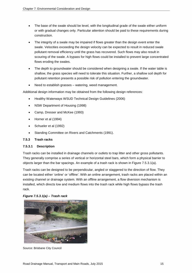
7.5.3 Trash racks
7.5.3.1 Description
Trash racks can be installed in drainage channels or outlets to trap litter and other gross pollutants. They generally comprise a series of vertical or horizontal steel bars, which form a physical barrier to objects larger than the bar spacings. An example of a trash rack is shown in Figure 7.5.3.1(a).
Trash racks can be designed to be perpendicular, angled or staggered to the direction of flow. They can be located either ‘online’ or ‘offline’. With an online arrangement, trash racks are placed within an existing channel or drainage system. With an offline arrangement, a flow diversion mechanism is installed, which directs low and medium flows into the trash rack while high flows bypass the trash rack.
Figure 7.5.3.1(a) – Trash rack
Source: Brisbane City Council
Road Drainage Manual, Transport and Main Roads, July 2015 15

Chapter 7: Environmental Consideration and Design
Advantages of trash racks include that they:
• are simple to construct
• trap all pollutants larger than the bar spacing and also retains smaller pollutants when the rack becomes partially blocked
• can be retrofitted into existing drainage systems
• collect litter at a single point.
Disadvantages of trash racks include that:
• they have potential to cause upstream flooding when material accumulates behind the trash rack (refer Figure 7.5.3.1(b))
• scouring at the base or sides of the rack if adequate protection is not implemented
• maintenance intensive, requiring manual cleaning either on an ‘as needs’ basis or as part of the programmed works for maintenance
• trapped material may be resuspended during large storm events.
Figure 7.5.3.1(b) – Trash rack and pollutants
Source: Brisbane City Council
7.5.3.2 Design guidelines
The most commonly used technique for sizing trash racks is an approach described in Department of Urban Services ACT Government (1994).
1. The length of the trash rack should be determined in conjunction with the trash rack height and the available space.
2. The height of the designed rack should be such that the rack is not overtopped by the design flood flow when 50% blocked.
3. Under submerged conditions, the required height of the trash rack is twice the depth at critical flow through the unblocked trash rack. For a trash rack consisting of vertical 10 mm bars at 40 mm spacing, this leads to:
3/2
26.1
=
rLQH
where H = rack height (m)
Q = design flow (m³/s)
Road Drainage Manual, Transport and Main Roads, July 2015 16

Chapter 7: Environmental Consideration and Design
Lr = length of rack (m)
4. The presence of downstream hydraulic controls can lead to submergence of the trash rack. Under these conditions (Beecham and Sablatnig 1994):
=
gvkh2
2
and
−
−= 2
2
45.045.1g
n
g
n
AA
AA
k
where h = head loss through the trash rack (m)
k = rack coefficient
v = average velocity through rack (m/s) = Q/An
g = gravitational acceleration (9.81 m/s²)
An = net area through bars (m²)
Ag = gross area of racks and supports (m²).
5. Trash racks have the potential to exacerbate upstream flooding if blocked. Hydraulic analysis should be carried out to investigate impacts arising from the rack being 50% and 100% blocked. The trash rack should be assessed for the EY 0.5, EY 0.2, AEP 2% and AEP 1% (ARI 2-year, 5-year, 50-year and 100-year) flood events.
Additional design information may be obtained from Department of Urban Services (1994), and Willing and Partners (1992).
7.5.4 Proprietary devices
7.5.4.1 Description
There are a number of manufactured devices, which are designed to remove specific pollutants such as coarse sediment, oil, grit and hydrocarbons from runoff. Each proprietary device is specifically designed to treat one or more pollutants associated with stormwater. The majority of these devices are designed to be located underground, as part of the stormwater network.
7.5.4.2 Design guidelines
The design considerations outlined in this section are for general guidance purposes only. Propriety pollutant control devices should be designed in accordance with the manufacturers’ recommendations in order to achieve the required pollutant control objectives.
Road Drainage Manual, Transport and Main Roads, July 2015 17

Chapter 7: Environmental Consideration and Design
Before devices can be considered and their suitability assessed, the pollutants to be removed from a flow need to be determined and the treated water quality objectives set. This involves establishing appropriate design criteria, such as:
• surface and underground drainage gradients
• catchment area
• pollutant characteristics (such as sediment diameter)
• location of installation
• requirements for maintenance access.
The assessment and selection of appropriate proprietary devices should include consideration of:
• ability to meet required water quality objectives
• proven ability to achieve the desired pollutant removal rate
• capital costs
• construction materials
• installation procedures
• drainage design criteria
− head loss
− crossfall
− hydraulic capacity
• maintenance procedures, such as:
− access
− frequency and cost
− spills
− disposal of pollutants
− inspection of control device.
7.5.5 Constructed wetlands
7.5.5.1 Description
Constructed wetlands are structures built with predominantly natural materials to reproduce the physical, chemical and biological processes of natural wetlands. They are used to remove a range of pollutants, including suspended solids, nutrients, heavy metals and other toxic or hazardous compounds. Their pollutant trapping efficiency varies with the type of pollutant, being moderate for oil and grease, moderate to high for sediments and nutrients.
Road Drainage Manual, Transport and Main Roads, July 2015 18

Chapter 7: Environmental Consideration and Design
Wetlands typically comprise an upstream inlet zone, a shallow macrophyte zone and a high flow bypass channel. The upstream inlet zone consists of a relatively deep, open water body or sediment basin with some fringing aquatic vegetation. The downstream macrophyte zone is a more permanent shallow water body with extensive vegetation. The bypass channel is used to protect the macrophyte zone from scour and vegetation damage (Water Sensitive Urban Design: Technical Design Guidelines for South East Queensland (Healthy Waterways), 2006).
Advantages of wetlands include that they:
• potentially achieve high sediment and nutrient retention efficiencies
• can be incorporated into the road corridor, thereby providing improved habitat and visual amenity in disturbed areas
• potentially can be retrofitted into existing sediment ponds/or detention basins.
Disadvantages of wetlands include that they have:
• either pre-treatment or removal mechanisms at the inlet to remove coarse sediment and litter
• large areas for construction
• a reliable inflow to ensure they remain ‘wet’, unless the wetland is designed to be ephemeral.
In addition, wetlands may:
• have a treatment performance which is highly sensitive to hydrologic and hydraulic design
• take up to three years to achieve optimal performance
• have a potential impact on public health and safety
• have adverse interactions (pollutant exchange) with groundwater in some situations.
Constructed wetlands generally require large areas of land, resulting in high construction costs. Maintenance cost of wetlands can be kept relatively low if the design provides for mechanised sediment removal facilities, as well as the inclusion of upstream pre-treatment devices for the trapping of coarse sediment and litter.
7.5.5.2 Design guidelines
Urban Stormwater Best Practice Environmental Management Guidelines (CSIRO 2006) outlines a number of design principles to consider before construction. These include:
• Establish a uniform flow distribution throughout the wetland. Avoid creating stagnant areas
• To enhance sedimentation, maximise the amount of time macrophytes are in contact with flow. This can be done by providing low flow velocities with healthy vegetation.
• Provide adequate wetland pre-treatment.
• Minimise organic matter loading.
• Maintenance requirements must be met in order to manage sediment build up and weed occurrence.
The design procedure outlines five general steps in the design of constructed wetlands and the reference, The Constructed Wetlands Manual – Department of Land and Water Conservation (NSW) 1998, is relevant to these five design steps.
Road Drainage Manual, Transport and Main Roads, July 2015 19

Chapter 7: Environmental Consideration and Design
1. Wetland location
Constructed wetlands can be located on a watercourse or adjacent to a watercourse. For road corridors, the preferred location is adjacent to a watercourse. In this case, the drainage system of the road can be designed to direct runoff from the local catchment and pavement surface into the wetland rather than directly into the watercourse. A high flow bypass channel around the wetland system can be designed such that sediments and vegetation within the wetland are not damaged during flood events.
The location of a wetland will depend on a number of factors, including:
• aquatic habitat and riparian vegetation of the receiving environment
• wetland size and available space in the road reserve
• topography
• reliability of low flows to maintain a permanent wetland
• groundwater conditions
• maintenance requirements.
2. Wetland size
The components of the wetland that need to be sized are the temporary and permanent storage volumes. The permanent storage zone encourages biofilm growth on the macrophytes (plants such as reeds, rushes and sedges) and maintains sedimentation. The temporary storage zone can be used to attenuate peak flows and to increase hydraulic residence time, thereby maximising the rate of pollutant removal.
As a rule of thumb, wetland areas in south-east Queensland should cover 2% – 4% of the contributing catchment area.
3. Pre-treatment measures
The removal of coarse sediment upstream of the wetland will minimise changes to depth profile and damage to macrophytes. The installation of a sediment trap and trash rack upstream of the wetland are recommended and will assist greatly in reducing the frequency and cost of maintenance.
4. Macrophyte planting requirements
A wetland should be divided into a number of zones to encourage macrophyte diversity. An open water zone will encourage UV disinfection and oxygenation. Shallow marsh, marsh and deep marsh zones encourage macrophyte diversity and uniform flow across the wetland.
5. Outlet structure
Outlet structures are important as they control the water level within the wetland. An appropriate water level optimises water quality improvement, achieves macrophyte diversity and provides for weed and mosquito control.
Four outlet varieties discussed in Victorian Stormwater Committee (1999) are risers, weirs, culverts and siphon outlets. These outlet devices should be assessed to determine the appropriate water level or hydraulic regime each would have on a wetland. The choice of outlet type will also be influenced by the basin morphology and hydrology.
Road Drainage Manual, Transport and Main Roads, July 2015 20

Chapter 7: Environmental Consideration and Design
Additional design information may be obtained from:
• Water Sensitive Urban Design: Technical Design Guidelines for South East Queensland (Healthy Waterways, 2006)
• Guidelines for Stabilising Waterways (SCRS 1991).
• Bioretention Technical Design Guidelines (Water by Design, October 2014).
7.5.6 Buffer zones
7.5.6.1 Description
Buffer zones are areas that are left undisturbed to provide some filtering and trapping of sediment (and therefore some heavy metals). Buffer zones are usually established upstream of sensitive receiving environments, such as natural wetlands, streams or bushland. Buffer zones preserve the existing vegetation and landscape, may be used as habitat corridor for wildlife and contribute to preserving biodiversity. They may require fencing to exclude traffic and to prevent damage to the vegetation.
Advantages of a buffer zone include that:
• it is applicable to all development areas
• it is able to reduce runoff volume by 30% to 50% more than grass filter strips
• it has low costs and requires low maintenance.
Disadvantages of a buffer zone include that:
• it has a limited ability to reduce pollutant loads
• it can only trap coarse sediments
• it is suitable for slopes between 1% and 10%.
7.5.6.2 Design guidelines
The design procedure below provides five general steps for the design of buffer zones.
1. Buffer zone dimensions
The performance of a buffer zone generally increases with increasing width and decreasing slope.
As a general guide, the width of a buffer zone (expressed in ‘m’) should be the greater of five times the slope (expressed as percentage (e.g. 50 m buffer width on a 10% slope) or 1.5 times the width of the disturbed area from which the sediments are mobilised. The latter generally applies to grassed buffers adjacent to the road pavement. In some locations these design rules may not need to be applied.
Grassed buffer zones
For maximum efficiency, the depth of sheet flow should not exceed the grass length. Grassed areas should be maintained with a minimum grass length of 50 mm (well-trimmed lawns are less effective although they tend to be more sought after).
2. Performance monitoring requirements
Buffer zones adjacent to high quality watercourses and environmentally sensitive areas should be wide enough to trap all visible sediment within the first quarter of the buffer zone width.
Road Drainage Manual, Transport and Main Roads, July 2015 21

Chapter 7: Environmental Consideration and Design
If buffer zones are to be effective, at least 75% of the ground should be covered by vegetation and weed growth should be controlled.
3. Slopes
Buffer zones are recommended for the control of sheet flow on slopes between 1% and 10%.
4. Fencing
Fencing can be used to exclude traffic from buffer zones, thus preventing damage to the vegetation and surface rutting.
5. Planning buffer zones
Buffer zones should be incorporated into the final landscaping plan and should be constructed (or retained) early in the development program.
7.5.7 Water quality ponds
7.5.7.1 Description
A water quality pond is a relatively deep open body of water, possibly with littoral macrophytes (reeds). Wet basins achieve pollutant removal through sedimentation. Their pollutant removal efficiency depends on the stormwater residence time and the amount of runoff detained in the basin. Pollutant removal efficiency increases with longer residence times and greater used storage volumes.
Advantages of water quality ponds include that they:
• can be used to trap coarse sediments and associated pollutants
• have the potential for stormwater re-use
• have a potentially high aesthetic or recreational value
• provide habitat for wildlife
• can generally be constructed at steeper sites than constructed wetlands.
Disadvantages of water quality ponds include that they:
• can be prone to eutrophication and thus have an adverse impact on downstream water quality
• have the potential to breed mosquitoes
• may cause habitat degradation upstream and downstream of the basin
• may require flocculation.
Large pond volumes may be required in regions with high rainfall intensities.
7.5.7.2 Design guidelines
Ideally, a continuous simulation approach should be undertaken due to the highly variable nature of catchment runoff and associated pollutant concentration. From the continuous simulation an appropriate storage volume could be selected on the basis of long-term performance rather than prescribed performance for a single event.
The size and capacity of water quality ponds should be such that stormwater is detained for as long as possible to promote effective treatment of pollutants, but should also guarantee that runoff generated during subsequent storms is captured and treated. The longer the residence time and the more water stored in the pond, the better the pollutant treatment.
Road Drainage Manual, Transport and Main Roads, July 2015 22

Chapter 7: Environmental Consideration and Design
Ideally, the pond should be protected from flood flows larger than the design storm flow. Provision of a high flow bypass channel is a means of reducing the risk of pond scouring but it is subjected to the site topographical constraints.
To enhance pollutant removal, the following design features should be considered:
• an effective residence time can be achieved by a pond length to width ratio of between 3:1 and 5:1
• the inlet to the pond should be located as far as possible from the outlet as possible
• to increase the length to width ratio or overcome problems with the inlet being too close to the outlet, berms and baffles may be installed to redirect flows.
The proper design of a pond outlet is critical to its performance. One option is to place a low level culvert at the Mean Operating Level (MOL) of the water quality pond. Between storms, the water level in the pond will drop below the MOL because of evaporation and infiltration losses. During storms, the water level will rise to and beyond the MOL, and water will flow out of the pond through the outlet.
Other outlet options include using orifice outlets, which may enhance flow detention during smaller storms or broad crested weirs. With the latter option, flood attenuation may not be as effective as with culvert or orifice outlets.
An access track should be provided for the maintenance of water quality ponds. Maintenance may include the following:
• mowing of banks and harvesting of macrophytes
• weed removal
• litter removal
• removal of accumulated sediment.
Monitoring of a water quality pond should be undertaken after large storm events at intervals not exceeding six months to assess the performance.
Additional design information may be obtained from Environmental Protection Agency (NSW) (1997), Horner et al (1994), and Schueler et al (1992).
7.6 Fauna passage
Section 3.3.1 of the Austroads Guide to Road Design – Part 5, is accepted for this section subject to the following amendments.
Addition(s)
1. Further reading on this topic is available in Fauna Sensitive Road Design: Volume 1 (DMR, 2000) and Fauna Sensitive Road Design: Volume 2 (DTMR 2010).
7.6.1 Identifying fauna passage criteria
Section 3.3.2 of the Austroads Guide to Road Design – Part 5 is accepted for this section.
Road Drainage Manual, Transport and Main Roads, July 2015 23

Chapter 7: Environmental Consideration and Design
7.6.2 Identify terrestrial and aquatic fauna pathways
Section 3.3.3 of the Austroads Guide to Road Design – Part 5 is accepted for this section subject to the following amendments.
Addition(s)
1. Specifically for fish passage requirements, Queensland Department of Agriculture, Fisheries and Forestry (DAFF) has mapping of fish passage waterways throughout Queensland. The mapping characterises waterways as low (green), moderate (amber), high (red) or tidal (purple) value for fish passage. If the project involves drainage structure works on any DAFF-mapped waterways, consideration of design requirements for fish passage is required.
7.6.3 Identify the species group
Section 3.3.4 of the Austroads Guide to Road Design – Part 5 is accepted for this section subject to the following amendments.
Addition(s)
1. It is also important to identify the actual animal species that are using the area. This information will be required for legislative approvals associated with construction of the infrastructure as different species.
Knowledge of the specific animal will also assist during design of infrastructure. For example, some species of frog prefer trees and leaf litter habitat while others prefer denser understorey of shrubs.
7.6.4 Consult with the relevant authority
It is critical early in the process to identify the legislation that applies to infrastructure being designed including any exemptions or self-assessments available for appropriate design.
This will be available within the environmental assessment for the project. In some cases, additional onsite surveys will be required in order to submit permit application and/or obtain the necessary approvals. The most commonly triggered pieces of legislation are provided in Table 7.6.4.
Table 7.6.4 – Commonly triggered legislation for the protection of fauna
Species Relevant legislation
Fish and other aquatic fauna Fisheries Act 1994 (Qld) Fisheries Regulation 2008 (Qld)
Species and communities of national significance*
Environmental Protection and Biodiversity Conservation Act 1999 (Cth) Environmental Protection and Biodiversity Conservation Regulations 2000 (Cth)
Other fauna
Nature Conservation Act 1992 (Qld) Nature Conservation (Wildlife management) Regulation 2006 (Qld) Nature Conservation (Wildlife) Regulation 2006 (Qld) Queensland Government Environmental Offsets Policy
Road Drainage Manual, Transport and Main Roads, July 2015 24

Chapter 7: Environmental Consideration and Design
For project specific requirements consult the project environmental assessment and project environmental officer.
7.6.5 Identify criteria affecting drainage design
Sections 3.3.6 – 3.3.9 of the Austroads Guide to Road Design – Part 5 is accepted for this section subject to the following amendments.
Addition(s)
1. For fish passage requirements (particularly culverts and causeways on waterways classified as moderate to major risk of impact) design criteria is likely to be set by the administering authority through self-assessable codes or through a required development approval. These conditions and requirements take precedence over the Austroads Guide to Road Design.
Design of fauna passage is a relatively young field. Design criteria is being improved continuously based on investigations and trials. Consult an environmental officer for the most recent information and design criteria.
Road Drainage Manual, Transport and Main Roads, July 2015 25