Embed Size (px)
Citation preview

CHAPTER 7 MISCELLANEOUS Bridge Plan Development Guide
March 1, 2007 7-1
CHAPTER 7 MISCELLANEOUS

CHAPTER 7 MISCELLANEOUS Bridge Plan Development Guide
March 1, 2007 7-2
7.1 Table of Contents
CHAPTER 7 MISCELLANEOUS......................................................................................................................... 7-1
7.1 TABLE OF CONTENTS .............................................................................................................................. 7-2 7.2 TITLE SHEET & ESTIMATED QUANTITIES ................................................................................................ 7-4
7.2.1 Typical Sheet Names and Contents.................................................................................................... 7-4 7.2.1.1 Title Sheet.................................................................................................................................................7-4 7.2.1.2 Estimated Quantities .................................................................................................................................7-5
7.2.2 Standard Notes................................................................................................................................... 7-6 7.2.2.1 SPECIFICATIONS...................................................................................................................................7-6 7.2.2.2 TRAFFIC DATA......................................................................................................................................7-6 7.2.2.3 DESIGN LOADING.................................................................................................................................7-6 7.2.2.4 MATERIALS............................................................................................................................................7-6 7.2.2.5 BASIC DESIGN STRESSES ...................................................................................................................7-7 7.2.2.6 HYDROLOGIC DATA ............................................................................................................................7-7 7.2.2.7 Coast Guard Permit...................................................................................................................................7-8 7.2.2.8 General Construction Notes ......................................................................................................................7-8
7.2.3 Checklists......................................................................................................................................... 7-12 7.2.3.1 Location Map..........................................................................................................................................7-12 7.2.3.2 Utilities List ............................................................................................................................................7-13 7.2.3.3 Maintenance Of Traffic...........................................................................................................................7-13 7.2.3.4 Scope Of Work .......................................................................................................................................7-13 7.2.3.5 Approximate Cost (Including Engineering) ............................................................................................7-13 7.2.3.6 Traffic Data.............................................................................................................................................7-13 7.2.3.7 Design Loading.......................................................................................................................................7-13 7.2.3.8 Specifications..........................................................................................................................................7-13 7.2.3.9 Materials .................................................................................................................................................7-14 7.2.3.10 Basic Design Stresses .............................................................................................................................7-14 7.2.3.11 Hydrologic Data......................................................................................................................................7-14 7.2.3.12 Coast Guard Permit Required .................................................................................................................7-14 7.2.3.13 Construction Notes .................................................................................................................................7-14
7.3 GEOTECHNICAL..................................................................................................................................... 7-15 7.3.1 Introduction ..................................................................................................................................... 7-15 7.3.2 Prerequisites .................................................................................................................................... 7-15 7.3.3 Standard Notes................................................................................................................................. 7-15 7.3.4 Typical Sheet Names and Contents.................................................................................................. 7-15
7.3.4.1 Boring Location Plan ..............................................................................................................................7-15 7.3.4.2 Interpretive Subsurface Profile ...............................................................................................................7-15 7.3.4.3 Boring Logs ............................................................................................................................................7-15
7.3.5 Checklists......................................................................................................................................... 7-17 7.3.5.1 Boring Location Plan ..............................................................................................................................7-17 7.3.5.2 Interpretive Subsurface Profile ...............................................................................................................7-18 7.3.5.3 Boring Logs ............................................................................................................................................7-19
7.4 STAGED CONSTRUCTION ....................................................................................................................... 7-20 7.4.1 Introduction ..................................................................................................................................... 7-20 7.4.2 Prerequisites .................................................................................................................................... 7-20 7.4.3 Detailing .......................................................................................................................................... 7-20 7.4.4 Typical Sheet Names and Contents.................................................................................................. 7-21
7.4.4.1 Staged Construction ................................................................................................................................7-21 7.4.5 Checklists......................................................................................................................................... 7-23
7.4.5.1 First Stage ...............................................................................................................................................7-23 7.4.5.2 Transitional Stages..................................................................................................................................7-24 7.4.5.3 Final Stage ..............................................................................................................................................7-25
7.5 TRAFFIC CONTROL ................................................................................................................................ 7-27 7.5.1 Detailing .......................................................................................................................................... 7-27 7.5.2 Typical Sheet Names and Contents.................................................................................................. 7-27
7.5.2.1 Detour Plan or Traffic Control Plan........................................................................................................7-27 7.5.3 Checklists......................................................................................................................................... 7-28

CHAPTER 7 MISCELLANEOUS Bridge Plan Development Guide
March 1, 2007 7-3
7.5.3.1 Detour Plan .............................................................................................................................................7-28 7.6 FISH PASSAGE STRUCTURES.................................................................................................................. 7-29
7.6.1 Introduction ..................................................................................................................................... 7-29 7.6.2 Prerequisites .................................................................................................................................... 7-29 7.6.3 Detailing .......................................................................................................................................... 7-29 7.6.4 References........................................................................................................................................ 7-29 7.6.5 Typical Sheet Names and Contents.................................................................................................. 7-30
7.6.5.1 Structure Sheet with Fish Weir ...............................................................................................................7-30 7.6.5.2 Weir Details ............................................................................................................................................7-31
7.6.6 Checklists......................................................................................................................................... 7-32 7.6.6.1 Structural Plan with Fish Weir................................................................................................................7-32 7.6.6.2 Structural Elevation with Fish Weir........................................................................................................7-33 7.6.6.3 Weir Elevations.......................................................................................................................................7-34 7.6.6.4 Weir Section ...........................................................................................................................................7-35 7.6.6.5 Longitudinal Notch Section ....................................................................................................................7-36 7.6.6.6 Transverse Notch Section .......................................................................................................................7-37
7.7 BRIDGE DECK JOINTS............................................................................................................................ 7-38 7.7.1 Introduction ..................................................................................................................................... 7-38 7.7.2 Prerequisites .................................................................................................................................... 7-38 7.7.3 Detailing .......................................................................................................................................... 7-38 7.7.4 References........................................................................................................................................ 7-38 7.7.5 Checklists......................................................................................................................................... 7-38 7.7.6 Armored Joint Notes ........................................................................................................................ 7-39
7.8 LIGHTING .............................................................................................................................................. 7-40 7.8.1 Introduction ..................................................................................................................................... 7-40 7.8.2 Prerequisites .................................................................................................................................... 7-40 7.8.3 Detailing .......................................................................................................................................... 7-40 7.8.4 Typical Sheet Names and Contents.................................................................................................. 7-41
7.8.4.1 Lighting Details ......................................................................................................................................7-41 7.8.4.2 Lighting Plan ..........................................................................................................................................7-42 7.8.4.3 Light Anchorage Plan .............................................................................................................................7-43 7.8.4.4 Light Anchorage Section ........................................................................................................................7-44
7.9 UTILITIES .............................................................................................................................................. 7-45 7.9.1 Introduction ..................................................................................................................................... 7-45 7.9.2 Prerequisites .................................................................................................................................... 7-45 7.9.3 Detailing .......................................................................................................................................... 7-45 7.9.4 Checklists......................................................................................................................................... 7-45
7.9.4.1 Utility Between Box Beams....................................................................................................................7-45 7.9.4.2 Utility Between Box Beams at Abutment ...............................................................................................7-46 7.9.4.3 Threaded Inserts in Precast Concrete ......................................................................................................7-47 7.9.4.4 Utility on Exterior Box Beam .................................................................................................................7-48 7.9.4.5 Utility Penetrating Abutment ..................................................................................................................7-49
7.10 ADDENDUMS TO THE PLANS.................................................................................................................. 7-50 7.10.1 Introduction................................................................................................................................. 7-50 7.10.2 Typical Sheet Names and Contents ............................................................................................. 7-50 7.10.3 Detailing ..................................................................................................................................... 7-50
7.11 HEARING PLANS.................................................................................................................................... 7-52 7.11.1 Introduction................................................................................................................................. 7-52 7.11.2 Prerequisites ............................................................................................................................... 7-52 7.11.3 Detailing ..................................................................................................................................... 7-53
7.11.3.1 Bold Text ................................................................................................................................................7-53 7.11.3.2 Color Reference ......................................................................................................................................7-53 7.11.3.3 Background Sheet ...................................................................................................................................7-57
7.11.4 References and Resources........................................................................................................... 7-57 7.12 COAST GUARD PERMITTING.................................................................................................................. 7-58

CHAPTER 7 MISCELLANEOUS Bridge Plan Development Guide
March 1, 2007 7-4
7.2 Title Sheet & Estimated Quantities
These sheets present design and construction specifications, materials and material strengths, technical data, and general construction methods. They serve to link the plans, specifications and estimate.
7.2.1 Typical Sheet Names and Contents
7.2.1.1 Title Sheet
Figure 7-1 Title Sheet
Will Contain:
1) MeDOT Logo
2) Title Information
3) Bridge Name
4) Crossing (river, stream, RR, etc.)
5) Town, City
6) County
7) Location Map
8) North Arrow
9) Bar Scale

CHAPTER 7 MISCELLANEOUS Bridge Plan Development Guide
March 1, 2007 7-5
10) Project Location
11) Project Length (Does not include transitions)
12) Project Number
13) Project Description (Bridge Replacement, Culvert Invert Lining, Sliplining, Deck Replacement, Wearing Surface Replacement, Bridge Rehabilitation, Bridge Painting, etc.)
14) Index of sheets
15) Bridge sheets & ROW map
16) Bridge standard details
17) Highway standard details
18) Signature block w/PE stamp
19) Hydrologic data
20) Traffic data
21) Specifications
May Contain:
1) Consultant Logo
7.2.1.2 Estimated Quantities
Figure 7-2 Estimated Quantities Sheet

CHAPTER 7 MISCELLANEOUS Bridge Plan Development Guide
March 1, 2007 7-6
Will Contain:
1) Table of Estimated Quantities
2) Construction Notes
7.2.2 Standard Notes
7.2.2.1 SPECIFICATIONS
DESIGN: Load and Resistance Factor Design per AASHTO LRFD Bridge Design Specifications Fourth Edition 2007.
DESIGN: Allowable Stress Design per AASHTO Standard Specifications for Highway Bridges 1996, and all supplementals thereto.
7.2.2.2 TRAFFIC DATA
Current (200X) AADT = XXXX
Future (20XX) AADT = XXXX
DHV - % of AADT = XX %
Design Hour Volume = XXX
Heavy Trucks (% of AADT) = XX %
Heavy Trucks (% of DHV) = XX %
Directional Distribution (% of DHV) = XX %
18 Kip Equivalent P 2.0 = XX
18 Kip Equivalent P 2.5 = XX
Design Speed = XX mph
7.2.2.3 DESIGN LOADING
LIVE LOAD: HL-93 Modified for Strength I (Truck only increased 25%)
7.2.2.4 MATERIALS
CONCRETE:
Structural Wearing Surface Class LP
Barriers, Curbs, Sidewalks, End Posts Class LP
Seals Class S
Precast Class P
Fill Fill
All Other Class A
REINFORCING STEEL: ASTM A615/A615M Grade 60

CHAPTER 7 MISCELLANEOUS Bridge Plan Development Guide
March 1, 2007 7-7
PRESTRESSING STRANDS: AASHTO 203 (ASTM A416),
Grade 270, Low Relaxation
STRUCTURAL STEEL:
All Material (unless otherwise noted) ASTM A709, Grade 50W (unpainted)
High Strength Bolts ASTM A325M, Type 3
7.2.2.5 BASIC DESIGN STRESSES
CONCRETE: f’c = 4,350 psi
PRECAST CONCRETE: f’c = XX psi f’ci = XX psi
REINFORCING STEEL: fy = 60,000 psi
PRESTRESSING STRANDS: fy = 270,000 psi
STRUCTURAL STEEL:
ASTM A709, Grade 345W Fy = 50,000 psi
ASTM A709, Grade 250 Fy = 36,000 psi
ASTM A325 Fu = 120,000 psi
7.2.2.6 HYDROLOGIC DATA
Drainage Area = _______sq mi
Design Discharge (Q50) = _______cfs
Check Discharge (Q100) = _______cfs
Headwater Elev. (Q50) = _______ft
Headwater Elev. (Q100) = _______ft
Discharge Velocity (Q50) = _______fps
Discharge Velocity (Q100) = _______fps
Headwater Elev. (Q1.1) = _______ft
Discharge Velocity (Q1.1) = _______fps
Mean Lower Low Water (MLLW) = -X.XX ft
Mean Low Water (MLW) = -X.XX ft
Mean Tide Level (MTL) = X.XX ft
Mean High Water (MHW) = X.XX ft
Mean Higher High Water (MHHW) = X.XX ft
20__ Predicted High Tide = X.XX ft

CHAPTER 7 MISCELLANEOUS Bridge Plan Development Guide
March 1, 2007 7-8
7.2.2.7 Coast Guard Permit
(The following note is used only when a Coast Guard Permit is required, and should be the only note to be put on the plans in reference to permits.)
COAST GUARD PERMIT REQUIRED
7.2.2.8 General Construction Notes
1) All utility facilities shall be adjusted by the respective utilities unless otherwise noted.
2) For easements, construction limits, and right-of-way lines, refer to Right of Way Map.
3) During construction, the road will be closed to traffic for a time period specified in the Special Provisions.
4) Place a 24 in. wide strip of Temporary Erosion Control Blanket on the side slopes along the top of the riprap and behind the wingwalls and headwalls.
5) All embankment material, except as otherwise shown, placed below Elevation XX, shall be Granular Borrow meeting the requirements of Subsection 703.19, Material for Underwater Backfill.
(The following note shall be shown on the plans when the quantity of clearing is one half acre or less and no separate payment is to be made.)
6) The clearing limits as shown on the plans are approximate. The exact limits will be established in the field by the Resident. Payment for clearing will be considered incidental to related Contract items.
(The following note is used when the clearing quantity is more than on half acre and a pay item for clearing is to be included.)
7) The clearing limits as shown on the plans are approximate. The actual clearing limits for payment will be established in the field by the Resident.
8) Place loam 2 inches deep on all new or reconstructed sideslopes or as directed by the Resident.
9) Do not excavate for Aggregate Subbase Course where existing material is suitable as determined by the Resident.
10) In areas where the Resident directs the Contractor not to excavate to the subgrade line shown on the plans, payment for removing existing pavement, grubbing, shaping, ditching, and compacting the existing subbase and layers of new subbase 6 inches or less thick will be made under appropriate equipment rental items.
(The following note is used when unscreened gravel such as aggregate subbase gravel is designated as surface material in the shoulders.)
11) Stones which cannot be rolled or compacted into the surface of the shoulder shall be removed by hand raking. Payment for hand raking will be considered incidental to Item 304.10 Aggregate Subbase Course -Gravel.
(The following note shall be used on newly constructed projects when the future AADT is 500 or more)

CHAPTER 7 MISCELLANEOUS Bridge Plan Development Guide
March 1, 2007 7-9
12) A NCHRP350 compliant guardrail end treatment shall be installed concurrently with the placement of each section of beam guardrail.
(The following note shall be used on newly constructed projects when the future AADT is less than 500)
13) A Low Volume Guardrail End shall be installed concurrently with the placement of each section of beam guardrail.
14) Extended-use Erosion Control Blanket, seeded gutters, riprap downspouts, and other gutters lined with Stone Ditch Protection shall be constructed after paving and shoulder work is completed, where it is apparent that runoff will cause continual erosion. Payment will be made under the appropriate Contract items.
(The following note is used on the plans for Reduced Berm Offsets)
15) Guardrail posts as shown in the Standard Details shall be modified from the indicated length of 6 feet to a length of 7 feet with an embedment of 4.5 feet. Payment will be considered incidental to the guardrail pay items.
16) Protective coating for concrete surfaces shall be applied to the following areas:
a) All exposed surfaces of concrete curbs and sidewalks,
b) Fascia down to drip notch,
c) All exposed surfaces of concrete transition barriers,
d) Concrete wearing surfaces,
e) Concrete barrier railing,
f) Top of abutment backwalls and to 12 inches below the top of backwalls on the back side.
17) Erosion Control Mix may be substituted in those areas normally receiving loam and seed as directed by the Resident. Placement shall be in accordance with Standard Specifications Section 619, Mulch. Payment will be made under Item 619.1401 Erosion Control Mix.
[The following two notes are used in conjunction with Standard Detail 610(2-4).]
18) Place riprap on sideslopes up to elevation XX.
19) Construct the riprap shelf at each abutment at elevation XX.
(The following five notes are used as needed.)
20) Bidders and Contractors may obtain a copy of the existing bridge plans by faxing a Request for Information to the Bid Contact Person. The plans are reproductions of the original drawings as prepared for the construction of the bridge. It is very unlikely that the plans will show any construction field changes or any alterations, which may have been made to the bridge during its life span.
21) Bidders and Contractors may obtain a copy of the hydrologic report of the bridge site by faxing a Request for Information to the Bid Contact Person. The hydrologic report is based on the Maine DOT’s interpretation of the information obtained for the subject site. No assurance is given that the information or the conclusions of the report will be representative of actual conditions at the time of construction.

CHAPTER 7 MISCELLANEOUS Bridge Plan Development Guide
March 1, 2007 7-10
22) Bidders and Contractors may obtain a copy of the bridge deck evaluation report of the existing bridge by faxing a Request for Information to the Bid Contact Person. The report contains visual inspection information and deck core data of the bridge. There is no assurance that the information or data is a true representation of the conditions of the entire deck.
23) Bidders and Contractors may obtain a copy of the project geotechnical report(s), Name of Report(s), MaineDOT Soils Report Number(s), date(s), by faxing a Request for Information to the Bid Contact Person.
24) Geotechnical information furnished or referred to in this plan set is for the use of the Bidders and Contractor. No assurance is given that the information or interpretations will be representative of actual subsurface conditions at the construction site. Maine DOT will not be responsible for the Bidder’s and Contractor’s interpretations of, or conclusions drawn from, the geotechnical information. The boring logs contained in the plan set present factual and interpretive subsurface information collected at discrete locations. Data provided may not be representative of the subsurface conditions between boring locations.
(The following note is to be used when removing an existing aluminum bridge rail.)
25) All aluminum bridge rail, rail posts, and associated hardware which are to be removed shall be carefully salvaged by the Contractor and will remain the property of the Department. Payment shall be incidental to related Contract items.
(Cofferdam pay items will be used when the use of such an item is clearly required. In situations where the need for a cofferdam is in question, then no cofferdam pay item would be included, and the following note would be put on the plans. Consequently, when a cofferdam pay item is included, this item must clearly identify the location at which it is intended to be used, particularly when both cofferdam pay items and the following note are included in the same contract. Furthermore, if both are used, the following note should be modified to clearly state which cofferdam is incidental.)
26) All costs for cofferdams, including pumping, maintenance, related temporary soil erosion and water pollution controls and removal will not be paid for directly, but will be considered incidental to related Contract Items.
(The following note is primarily intended to inform the Bidders that the existing structure to be removed is coated with lead-based paint. Therefore any contract where the existing structure is to be removed, and the structure contains lead paint, should have this note on the plans. A similar note should be created and included in any contract where the existing structure contains lead paint and is to be rehabilitated.)
27) The existing bridge shall be removed by, and become the property of, the Contractor. The steel portions of the existing bridge are coated with a lead-based paint system. The Contractor is responsible for the containment, proper management and disposal of all lead-contaminated hazardous waste generated by the process of demolishing the bridge. The Contractor is responsible for implementing appropriate OSHA mandated personal protection standards related to this process. Once the existing bridge is removed, the Contractor is solely responsible for the care, custody and control of the components of the existing bridge and any hazardous waste generated as a result of storage, recycling, or disposal of the bridge components, including the lead-coated steel. The Contractor shall recycle or reuse the steel in accordance with Maine Department of Environmental

CHAPTER 7 MISCELLANEOUS Bridge Plan Development Guide
March 1, 2007 7-11
Protection’s “Maine Hazardous Waste Management Regulations,” Chapter 850. A copy of this regulation is available at the MaineDOT’s offices on Child Street in Augusta. Payment for all labor, materials, equipment, and other costs required to remove and dispose of the existing bridge will be considered incidental to the bridge removal pay item.
(The following note may be included on the plans where the existing bridge, regardless of type or size, is to be removed and a demolition plan is necessary.)
28) The Contractor shall submit a Bridge Demolition Plan to the Resident at least 10 business days prior to the start of demolition work. This plan shall outline the methods and equipment to be used to remove and dispose of all materials included in the existing bridge. No work related to the removal of the bridge shall be undertaken by the Contractor until the MaineDOT has reviewed the Bridge Demolition Plan for appropriateness and completeness. Payment for all work necessary for developing, submitting and finalizing the Demolition Plan will be considered incidental to the bridge removal pay item.
(The following note shall be included on the plans whenever lump sum items are included in the contract.)
29) Quantities included for pay items measured and paid by Lump Sum are estimated quantities and are provided by the MaineDOT for informational purposes only. Lump Sum items will be paid for at the Contract Bid amount, with no addition or reduction in payment to the Contractor if the actual final quantities are different from the MaineDOT provided estimated quantities unless:
If a Lump Sum pay item is eliminated, the requirements of Standard Specification Section 109.2, Elimination of Items, will take precedence.
If other Contract Documents specifically allow a change in payment for a Lump Sum pay item, those requirements will be followed.
If a design change results in changes to estimated quantities for Lump Sum pay items, price adjustments will be made in accordance with Standard Specification Section 109.7, Equitable Adjustments to Compensation.

CHAPTER 7 MISCELLANEOUS Bridge Plan Development Guide
March 1, 2007 7-12
7.2.3 Checklists
7.2.3.1 Location Map
Figure 7-3 Location Map

CHAPTER 7 MISCELLANEOUS Bridge Plan Development Guide
March 1, 2007 7-13
A location map needs to be provided, typically on the first sheet along with the plan view. Show the following:
1) Project location: cut the map such that it contains both the project and a local landmark such as an adjacent town.
2) Scale: show a bar scale.
3) North arrow: typically aligned with “up” on the page.
7.2.3.2 Utilities List
The list on the preliminary plan may include all of the utilities in the town because it may be the only information that you have at this time. The final list should only include the utilities within the project limits.
(Reference the Bridge Design Guide - Appendix D for the most up to date format)
7.2.3.3 Maintenance Of Traffic
Describe the maintenance of traffic in very general terms. If it is a bridge closure, tell how long the duration of the closure will be. If it is a detour over nearby roads tell which roads if you can. If it is an on site detour tell how many lanes of traffic will be maintained and by what method.
7.2.3.4 Scope Of Work
This is preferably written in the order that the work will be done.
7.2.3.5 Approximate Cost (Including Engineering)
7.2.3.6 Traffic Data
7.2.3.7 Design Loading
Sometimes the following verbiage is added on pipe type projects:
(Truck only increased 25%)
7.2.3.8 Specifications
The specifications note as it appears in the Microstation settings manager is not worded the same as it is in the Bridge Design Guide. The correct year should be stated in the BDG and updated when AASHTO is updated so that everyone will be made aware of the change.

CHAPTER 7 MISCELLANEOUS Bridge Plan Development Guide
March 1, 2007 7-14
7.2.3.9 Materials
7.2.3.10 Basic Design Stresses
7.2.3.11 Hydrologic Data
7.2.3.12 Coast Guard Permit Required
7.2.3.13 Construction Notes

CHAPTER 7 MISCELLANEOUS Bridge Plan Development Guide
March 1, 2007 7-15
7.3 Geotechnical
7.3.1 Introduction
The MeDOT geotechnical plans are typically developed by the Material Testing and Exploration unit in Bangor. They provide information on the subsurface soil conditions.
7.3.2 Prerequisites
You will need:
1) Complete topo
2) Final alignment
3) Plan and Profile views
4) Boring Locations
5) Boring Data
7.3.3 Standard Notes
Reference Chapter 7 General Construction Notes for geotechnical related notes.
7.3.4 Typical Sheet Names and Contents
7.3.4.1 Boring Location Plan
7.3.4.2 Interpretive Subsurface Profile
7.3.4.3 Boring Logs
When there is room, the Boring Location Plan and Interpretive Subsurface Profile are combined on the same sheet.

CHAPTER 7 MISCELLANEOUS Bridge Plan Development Guide
March 1, 2007 7-16
Figure 7-4 Boring Location Plan and Interpretive Subsurface Profile
Will Contain:
1) Survey Plan with Boring Locations
2) Foundation Profile

CHAPTER 7 MISCELLANEOUS Bridge Plan Development Guide
March 1, 2007 7-17
7.3.5 Checklists
7.3.5.1 Boring Location Plan
Figure 7-5 Boring Location Plan
Intro: Boring Location Plan shows boring locations.
Sheet up: belongs on Boring Location Plan Sheet
Scale: same as bridge plan, usually 1”=25’
Draw:
1) Bridge Plan
2) Temporary Detour
3) Contours
4) Survey
5) Boring Locations
Label:
1) Detail Name “PLAN”
2) Scale with Bar Scale
3) Boring Symbol Legend
CHAPTER 7 MISCELLANEOUS Bridge Plan Development Guide
March 1, 2007 7-18
7.3.5.2 Interpretive Subsurface Profile
Figure 7-6 Interpretive Subsurface Profile
Intro: Interpretive Subsurface profile shows soils, ledge, and boring locations.
Sheet up: belongs on Interpretive Subsurface Profile sheet or combined with the Boring Location Plan
Scale: same as profile, 1”=25 horizontal, 1”=5’ vertical
Draw:
1) Profile (start with complete bridge profile and extend vertically)
CHAPTER 7 MISCELLANEOUS Bridge Plan Development Guide
March 1, 2007 7-19
2) Soils
3) Ledge
4) Boring locations
Label:
1) Detail Name (“PROFILE”)
2) Scale (w/ Bar Scale)
3) Horizontal and Vertical Grid Lines
4) Soils
5) Borings
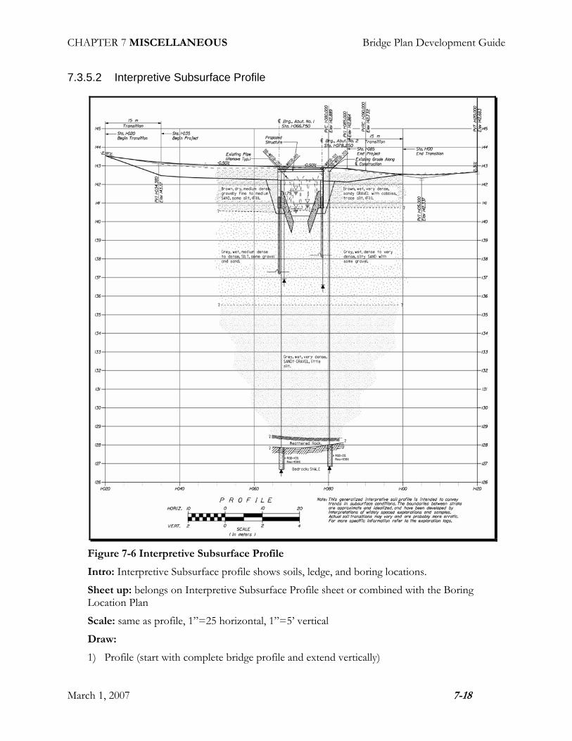
7.3.5.3 Boring Logs
Figure 7-7 Boring Logs
CHAPTER 7 MISCELLANEOUS Bridge Plan Development Guide
March 1, 2007 7-20
7.4 Staged Construction
7.4.1 Introduction
The staged construction sheet consists of a series of transverse sections showing the maintenance of traffic during removal of the existing bridge and construction of the new bridge.
7.4.2 Prerequisites
The following information should be gathered before you begin detailing:
1) Existing bridge transverse section
2) New bridge transverse section
3) Maintenance of traffic scheme for vehicular traffic and if required, pedestrian traffic
4) Location of existing and proposed utilities on bridge.
5) Staged Construction Notes
7.4.3 Detailing
The number of construction stages varies between projects and depends on individual project requirements. Shading can be use to indicate portions of existing bridge to be removed.
The Staged Construction Notes play an important role in communicating the Staged Construction scheme. Make sure the details accurately reflect the scheme presented in the notes.

CHAPTER 7 MISCELLANEOUS Bridge Plan Development Guide
March 1, 2007 7-21
7.4.4 Typical Sheet Names and Contents
7.4.4.1 Staged Construction
Figure 7-8 Staged Construction Sheet (Typical Bridge)
CHAPTER 7 MISCELLANEOUS Bridge Plan Development Guide
March 1, 2007 7-22
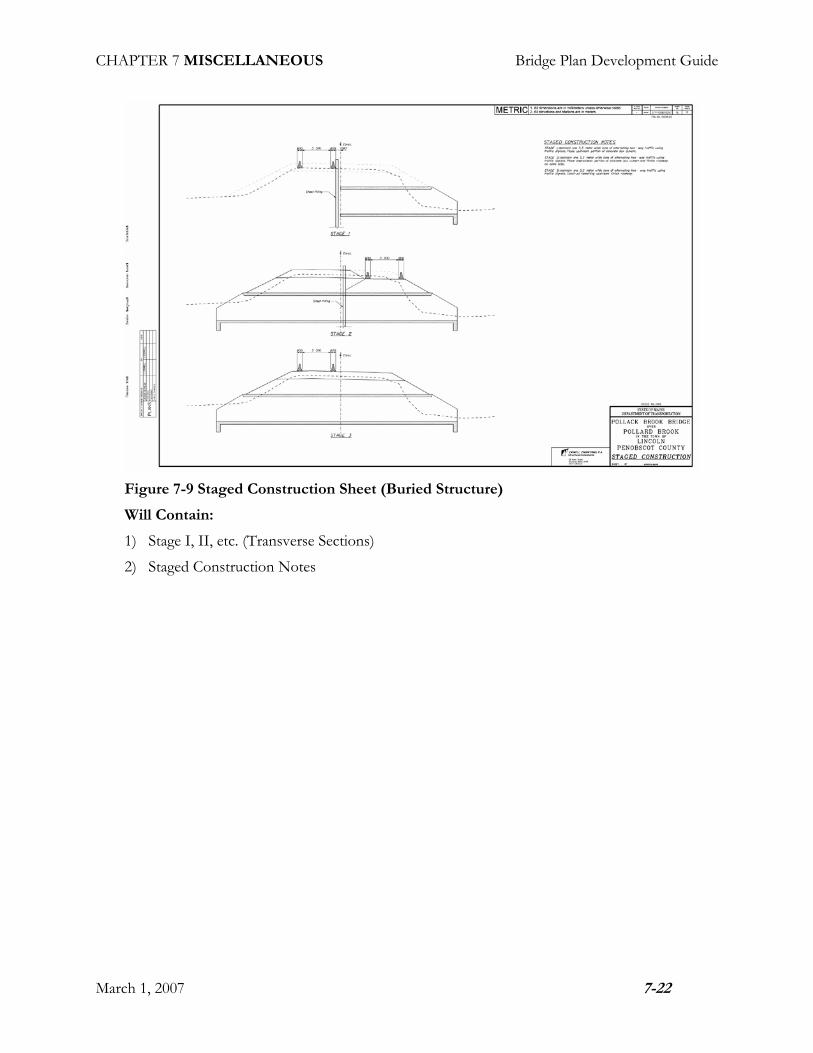
Figure 7-9 Staged Construction Sheet (Buried Structure)
Will Contain:
1) Stage I, II, etc. (Transverse Sections)
2) Staged Construction Notes

CHAPTER 7 MISCELLANEOUS Bridge Plan Development Guide
March 1, 2007 7-23
7.4.5 Checklists
7.4.5.1 First Stage
Figure 7-10 Staged Construction (Stage I)
Intro: Transverse section showing first stage of construction: shifting traffic to one side of bridge and removing the other.
Sheet up: Belongs in the upper left of the Staged Construction sheet.
Scale: ¼“.
Draw:
1) Centerline of Existing Construction/Working Line
2) Transverse section of existing bridge. Shade portion to be removed.
3) Temporary concrete barriers
4) Existing utilities supported from bridge
Dimension:
1) Temporary travel way and if required, pedestrian way.
2) Construction joint
Label:
1) Temporary concrete barrier
2) Maintain one-way/two-way traffic
3) Maintain pedestrian traffic
4) Construction joint

CHAPTER 7 MISCELLANEOUS Bridge Plan Development Guide
March 1, 2007 7-24
7.4.5.2 Transitional Stages
Figure 7-11 Staged Construction (Early Intermediate Stage)
Figure 7-12 Staged Construction (Late Intermediate Stage)
Intro: Transverse sections showing intermediate stages of construction: constructing portions of new bridge, shifting of traffic to new bridge and removing remaining portion of old bridge. The number of stages depends on individual project requirements.
Sheet up: Belongs on Staged Construction Sheet. Check sheet up before proceeding. If all stages won’t fit in a vertical alignment, locate subsequent stages so that they read left to right.
Scale: ¼“

CHAPTER 7 MISCELLANEOUS Bridge Plan Development Guide
March 1, 2007 7-25
Draw:
1) Centerline of Existing Construction/Working Line
2) Centerline of Proposed Construction/Working Line
3) Transverse sections of the existing and new bridge as required showing the progression of construction. Shade portions of existing bridge to be removed.
4) Temporary concrete barriers
5) Temporary sidewalks, if required
6) Existing utilities supported from bridge
Dimension:
1) Temporary travel way and if required, pedestrian way.
2) Offset between Existing and Proposed Construction/Working Line
Label:
1) Temporary concrete barrier
2) Maintain one-way traffic
3) Maintain pedestrian traffic
4) Construction joint
7.4.5.3 Final Stage
Figure 7-13 Staged Construction (Final Stage)
Intro: Transverse section showing completed bridge. During the final stage additional shifting traffic may be required to complete sidewalks, rails and paving.

CHAPTER 7 MISCELLANEOUS Bridge Plan Development Guide
March 1, 2007 7-26
Sheet up: Belongs on Staged Construction Sheet. Check sheet up before proceeding. If all stages won’t fit in a vertical alignment, locate subsequent stages so that they read left to right.
Scale: ¼“.
Draw:
1) Centerline of Existing Construction/Working Line
2) Centerline of Proposed Construction/Working Line
3) Transverse section of completed bridge
4) Temporary concrete barriers
5) Utilities supported from bridge
Dimension:
1) Temporary travel way
Label:
1) Maintain one-way/two way traffic
2) Traffic Control
3) Introduction
4) Prerequisites

CHAPTER 7 MISCELLANEOUS Bridge Plan Development Guide
March 1, 2007 7-27
7.5 Traffic Control
7.5.1 Detailing
Sometimes the traffic control plans are drawn by the detailer as part of the contract plans. Sometimes they are in the form of a specification, and included in the contract book. Then again, sometimes they are required to be developed by the Contractor. Check with the designer to see how this will be handled.
7.5.2 Typical Sheet Names and Contents
7.5.2.1 Detour Plan or Traffic Control Plan
Figure 7-14 Detour Plan
Will Contain:
1) Detour Plan

CHAPTER 7 MISCELLANEOUS Bridge Plan Development Guide
March 1, 2007 7-28
7.5.3 Checklists
7.5.3.1 Detour Plan
Figure 7-15 Detour Plan
Intro: shows signage requirements on a map of the vicinity of the project
Sheet up: belongs on Detour Plan Sheet
Scale: start from location map of same scale as title sheet.
Draw:
1) Location Map
2) Sign types and locations
Label:
1) Project Location
2) Towns, Route Numbers, Bodies of Water
3) Location and orientation of each sign type
CHAPTER 7 MISCELLANEOUS Bridge Plan Development Guide
March 1, 2007 7-29
7.6 Fish Passage Structures
7.6.1 Introduction
One of the important considerations of designing a bridge is maintaining the ability of fish to be able to pass through the bridge. Often time’s metal pipe inverts are too high and have very little flow. This can inhibit fish passage. This condition can be made worse when the invert of the pipe needs to be rehabilitated and concrete is added thus raising the invert. One of the ways to mitigate the situation is by utilizing a pool and weir system. The following is one example of a weir system constructed inside a pipe.
7.6.2 Prerequisites
You will need:
1) Existing Survey with invert elevations
2) Proposed and checked bridge structure geometry design
3) Reinforcement Design
7.6.3 Detailing
Details for fish weirs are explicit rather than performance-based. The Contractor is the main client to consider when detailing.
The geometry of these structures and can be a challenge for the designer to nail down, and a challenge to detail. The location and elevations of the weirs and the notches can be subjective, but are key to the systems success.
7.6.4 References
Maine Department of Transportation Fish Passage Policy & Design Guide

CHAPTER 7 MISCELLANEOUS Bridge Plan Development Guide
March 1, 2007 7-30
7.6.5 Typical Sheet Names and Contents
7.6.5.1 Structure Sheet with Fish Weir
Figure 7-16 Structure Sheet with Fish Weir
The fish weir may be shown on a structure sheet.
Will Contain:
1) Plan
2) Elevation
3) Section
May Contain:
1) Other Details
2) Notes
CHAPTER 7 MISCELLANEOUS Bridge Plan Development Guide
March 1, 2007 7-31
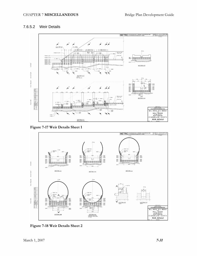
7.6.5.2 Weir Details
Figure 7-17 Weir Details Sheet 1
Figure 7-18 Weir Details Sheet 2
CHAPTER 7 MISCELLANEOUS Bridge Plan Development Guide
March 1, 2007 7-32
You may require more than one weir detail sheet, depending on how many sections you need to cut.
May Contain:
1) Weir Elevations
2) Weir Sections
3) Notes
7.6.6 Checklists
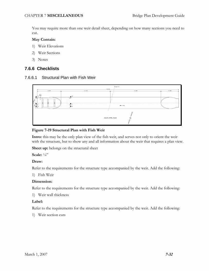
7.6.6.1 Structural Plan with Fish Weir
Figure 7-19 Structural Plan with Fish Weir
Intro: this may be the only plan view of the fish weir, and serves not only to orient the weir with the structure, but to show any and all information about the weir that requires a plan view.
Sheet up: belongs on the structural sheet
Scale: ¼”
Draw:
Refer to the requirements for the structure type accompanied by the weir. Add the following:
1) Fish Weir
Dimension:
Refer to the requirements for the structure type accompanied by the weir. Add the following:
1) Weir wall thickness
Label:
Refer to the requirements for the structure type accompanied by the weir. Add the following:
1) Weir section cuts

CHAPTER 7 MISCELLANEOUS Bridge Plan Development Guide
March 1, 2007 7-33
7.6.6.2 Structural Elevation with Fish Weir
Figure 7-20 Structural Elevation with Fish Weir
Intro: this elevation shows the relationship between the weir and the structure.
Sheet up: belongs on the structural sheet
Scale: ½”
Draw:
Refer to the requirements for the structure type accompanied by the weir. Add the following:
1) Fish Weir
2) Reinforcing
3) Staff Gage
Label:
Refer to the requirements for the structure type accompanied by the weir. Add the following:
1) Weir
2) Reinforcing

CHAPTER 7 MISCELLANEOUS Bridge Plan Development Guide
March 1, 2007 7-34
7.6.6.3 Weir Elevations
Figure 7-21 Weir Elevation 1
Figure 7-22 Weir Elevation 2
Intro: the weir elevations are really longitudinal sections cut to show the reinforcing steel. In the case of the sample project, two elevation were required, one to show the reinforcing in the walls, a second to show the reinforcing through the middle of the weir.
Sheet up: belongs on a weir details sheet.
Scale: ½” = 1’-0”
Draw:
1) Structure
2) Fish Weir

CHAPTER 7 MISCELLANEOUS Bridge Plan Development Guide
March 1, 2007 7-35
3) Reinforcing Steel
4) Ledge
Dimension:
1) Limits of concrete
2) Reinforcing Steel
Label:
1) Detail Name
2) Reinforcing Steel
3) Section Cuts
4) Ledge
7.6.6.4 Weir Section
Figure 7-23 Weir Section
Intro: sections will be required to show the reinforcing steel along the limits of the weir.
Sheet up: belongs on a weir details sheet
Scale: ½” = 1’-0”
Draw:
1) CL Structure
2) Structure
3) Limits of Weir Concrete

CHAPTER 7 MISCELLANEOUS Bridge Plan Development Guide
March 1, 2007 7-36
4) Ledge
5) Reinforcing Steel
Dimension:
1) Reinforcing Steel
Label:
1) Label Name
2) CL Structure
3) Reinforcing Steel
7.6.6.5 Longitudinal Notch Section
Figure 7-24 Longitudinal Notch Section
Intro: shows the typical notch geometry
Sheet up: belongs on a weir details sheet
Scale: 1” or 1½” = 1’-0”
Draw:
1) Limits of Concrete Weir Rib
2) Notch
Dimension:
1) Notch
2) Rib
Label:
1) Detail Name

CHAPTER 7 MISCELLANEOUS Bridge Plan Development Guide
March 1, 2007 7-37
2) Weir Rib
3) Notch Slope
4) Section Cut
7.6.6.6 Transverse Notch Section
Figure 7-25 Transverse Notch Section
Intro: shows the typical notch geometry
Sheet up: belongs on a weir details sheet
Scale: 1” or 1½” = 1’-0”
Draw:
1) CL Pipe
2) Limits of Concrete Weir Rib
3) Notch
Dimension:
1) Notch Width
Label:
1) Detail Name
2) CL Structure
CHAPTER 7 MISCELLANEOUS Bridge Plan Development Guide
March 1, 2007 7-38
7.7 Bridge Deck Joints
7.7.1 Introduction
Bridge deck joints protect the bearing areas from corrosion and move with the structure. They come in every shape and size. It is common to rehabilitate the deck joint at the same time the wearing surface is replaced or rehabilitated.
7.7.2 Prerequisites
1) Assessment of the existing condition of the joint if it is to be rehabilitated. Measurements and locations of damaged areas. Pictures of the joint can be very useful.
2) Joint opening measurements taken in several different places along the joint, and the temperature recorded at the time the measurements were taken.
3) Joint Design (don’t forget the curb or sidewalk area)
4) Joint welding information/design (if applicable)
5) Adjustment device design (if applicable)
6) Existing Plans (existing shop drawings of the joint may also be available)
7) Wearing surface thickness
7.7.3 Detailing
MaineDOT Standard Details take the place of most of the design related detailing on new projects. The lion’s share of deck joint detailing happens when the structure is rehabilitated. There are so many variations of deck joints that it is impractical to show all of the examples here. It is very helpful to find an existing set of plans to go by. Flaws in new joint designs have a way of becoming more evident as it is being detailed. Be aware of conflicts around the curb and sidewalk plates and at the transition barrier. On skewed structures, check this area along the whole temperature range for potential projections that could cause problems for snow plows.
7.7.4 References
Bridge Program Deck Joint Technical Resource person
Bridge Design Manual
MaineDOT Standard Details
Bridge Program Technical Library
7.7.5 Checklists
Plan
Elevation
North Arrow

CHAPTER 7 MISCELLANEOUS Bridge Plan Development Guide
March 1, 2007 7-39
Skew Angle
Designation of which end (location of seal)
Cross-section
Weld size and designation (symbols)
Treatment of welds where seal passes over it
Anchorage devices
Location of seal bars (compression seal)
Size of rolled steel members
Notes
7.7.6 Armored Joint Notes
The following notes are required when using compression seals. A Compression Seal Adjustment Chart shall be shown on the plans – see page 1060(4) of the BDG
1) The seal(s) to be furnished shall have a minimum Movement Rating(s) as follows:
Abutment No. 1 = XX inch
Abutment No. 2 – XX inch
2) The Resident shall approve the seals prior to fabrication of the Expansion Device.
CHAPTER 7 MISCELLANEOUS Bridge Plan Development Guide
March 1, 2007 7-40
7.8 Lighting
7.8.1 Introduction
Occasionally a lighting system is required on a bridge. Here are some guidelines for detailing.
7.8.2 Prerequisites
You will require:
1) Finished superstructure structural plans
2) Light standard locations
3) Light standard anchorage system
4) Light standard utility requirements (conduits, junction boxes)
5) Lighting Notes
7.8.3 Detailing
Lighting details are explicit rather than performance-based. The Contractor is the chief client to consider when detailing.

CHAPTER 7 MISCELLANEOUS Bridge Plan Development Guide
March 1, 2007 7-41
7.8.4 Typical Sheet Names and Contents
7.8.4.1 Lighting Details
Figure 7-26 Lighting Details Sheet
Will Contain:
1) Lighting Plan
2) Bridge Lighting Notes
3) Light Anchorage Plan
4) Light Anchorage Section
May Contain:
1) Lamp Standard Details
2) Junction Box Detail

CHAPTER 7 MISCELLANEOUS Bridge Plan Development Guide
March 1, 2007 7-42
7.8.4.2 Lighting Plan
Figure 7-27 Lighting Plan
Intro: This plan shows the location of light standards in relation to working points along the superstructure.
Sheet up: belongs on Lighting Details Sheet at the top
Scale: 1”=25’, larger or smaller as req’d to fit on sheet
Draw:
1) CL Construction/Working Line
2) CL Light Standards
3) Limits of Concrete (& other superstructure details for perspective, i.e. curbs, sidewalks, bridge drains, etc.)
4) Light Standard
5) Expansion Joints
Dimension:
The working line for the purpose of locating light standards will be the fascia. Dimensions shall be given along the fascia for a curved bridge.
Working points will be the intersection of the substructure centerlines with the fascia.
1) Location of Light Standards
2) Expansion Joints
Label:
1) Detail Name “LIGHTING PLAN”
2) North Arrow
3) CL Construction
4) CL Brg. Substructures (with Station)
5) CL Light Standard
6) Expansion Joints

CHAPTER 7 MISCELLANEOUS Bridge Plan Development Guide
March 1, 2007 7-43
7.8.4.3 Light Anchorage Plan
Figure 7-28 Light Anchorage Plan
Intro: the light anchorage plan shows the structural anchorage, utility conduits, and service boxes required to support the lighting system.
Sheet up: belongs on lighting details sheet, below plan
Scale: 1”=1’-0”
Draw:
1) CL Light Standard
2) CL Utility Conduits
3) Fascia
4) Face of Curb
5) Utilities
6) Reinforcing Steel/Anchorages
Dimension:
1) Location & Spacing of Reinforcing/Anchorage
Label:
1) Detail Name (“LIGHT ANCHORAGE PLAN”)
2) CL Light Standard
3) CL Conduits
4) Utilities
5) Reinforcing Steel/Anchorage

CHAPTER 7 MISCELLANEOUS Bridge Plan Development Guide
March 1, 2007 7-44
7.8.4.4 Light Anchorage Section
Figure 7-29 Light Anchorage Section
Intro: transverse section of the structural anchorage, utility conduits, and service boxes required to support the lighting system.
Sheet up: belongs on lighting details sheet below plan and to the right of light anchorage plan
Scale: 1”=1’-0”
Draw:
1) CL Conduits
2) Transverse section of the slab near the fascia, including
a) Limits of concrete deck
b) Wearing surface
c) Curb
d) Outer beam
3) Reinforcing/Anchorage
4) Utilities
Dimension:
1) Location of Conduits, tied to limits of concrete
2) Location and Embedment of Reinforcing/Anchorage
Label:
1) Detail Name (“LIGHT ANCHORAGE DETAIL”)
2) CL Conduits
CHAPTER 7 MISCELLANEOUS Bridge Plan Development Guide
March 1, 2007 7-45
7.9 Utilities
7.9.1 Introduction
When utilities are attached to bridges we are sometimes called upon to develop some unique support systems and details. Often time’s utility conduits are cast into concrete sidewalks or curbs, or externally attached to the superstructure, and pass through the substructure.
7.9.2 Prerequisites
1) Utility support design or conceptual sketches
2) Proposed Utility location/elevations
7.9.3 Detailing
Sometimes the details are explicit and sometimes they are more performance based. If for example, the support system is a steel support that is attached to the concrete deck, then the utility company is usually responsible for designing the support systems, and MaineDOT usually will show some performance based conceptual drawings on the plans. If the support system is integral with the concrete in the bridge structure, then the detailer may end up developing more explicit details.
7.9.4 Checklists
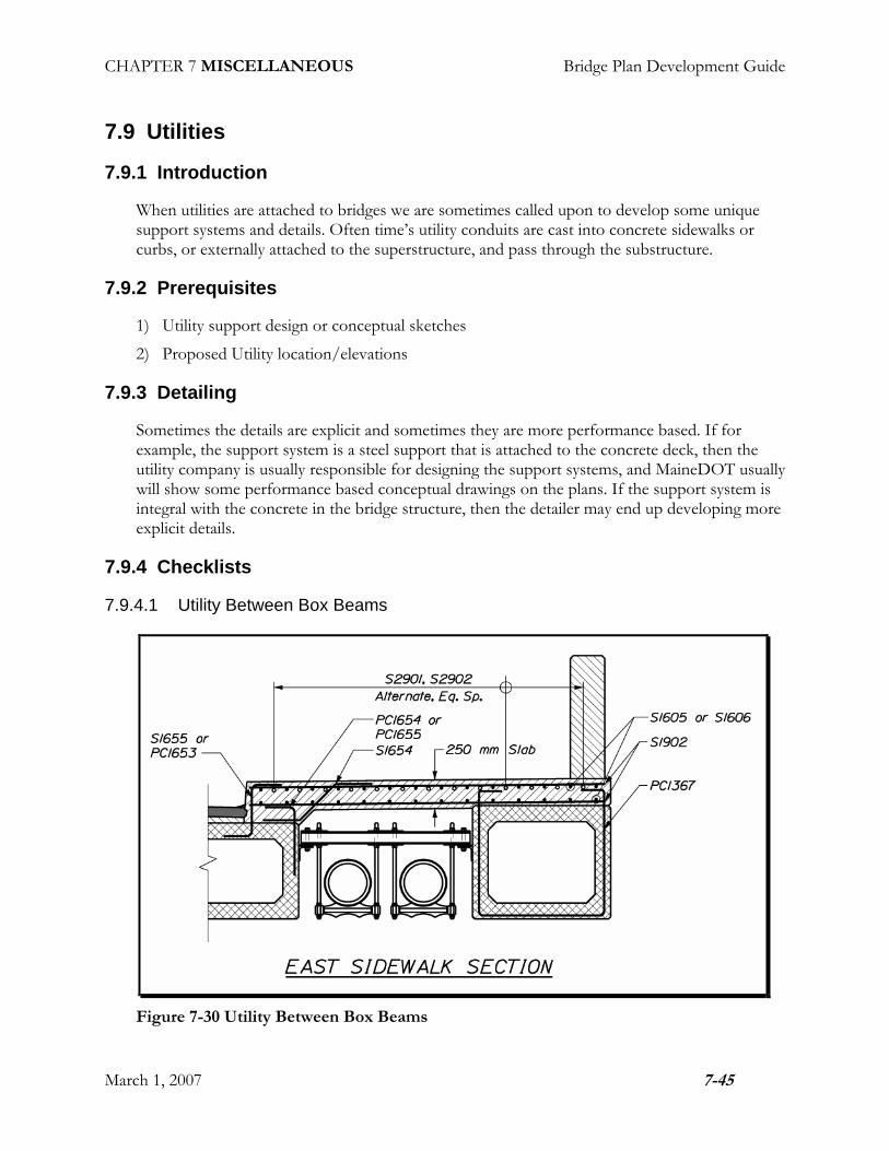
7.9.4.1 Utility Between Box Beams
Figure 7-30 Utility Between Box Beams

CHAPTER 7 MISCELLANEOUS Bridge Plan Development Guide
March 1, 2007 7-46
Intro: This support system involves supporting water mains from hangers. These hangers suspend from a diaphragm that is anchored into precast concrete box beams. The section shown is provided to show sidewalk reinforcement. It is also a good section to diagrammatically show the relationship between the utility and the superstructure
Sheet up: this section is shown on a superstructure details sheet.
Scale: ½” = 1’-0”
Draw:
1) Superstructure
2) Water Main
3) Water Main Support
7.9.4.2 Utility Between Box Beams at Abutment
Figure 7-31 Utility Between Box Beams at Abutment
Intro: this utility system requires the construction of a diaphragm of concrete at the abutment. It requires reinforcing steel, anchors/dowels, and pipe sleeves. A similar section is required to show reinforcing at the pier.
Sheet up: this transverse section was shown on a superstructure details sheet.
Scale: ½” = 1’-0”
Draw:
1) Utility

CHAPTER 7 MISCELLANEOUS Bridge Plan Development Guide
March 1, 2007 7-47
2) Pipe Sleeves
3) Reinforcing Steel
4) Limits of Superstructure concrete
5) Limits of Abutment Concrete
Dimension:
1) Utility Location (in relation to reference lines when possible)
2) Reinforcing Steel
Label:
1) Utility
2) Reinforcing Steel
3) Bottom of Utility Elevation
7.9.4.3 Threaded Inserts in Precast Concrete
Figure 7-32 Threaded Inserts in Precast Concrete
CHAPTER 7 MISCELLANEOUS Bridge Plan Development Guide
March 1, 2007 7-48
Intro: utilities supported on precast concrete may require threaded inserts into the precast. These need to be clearly shown on the precast details.
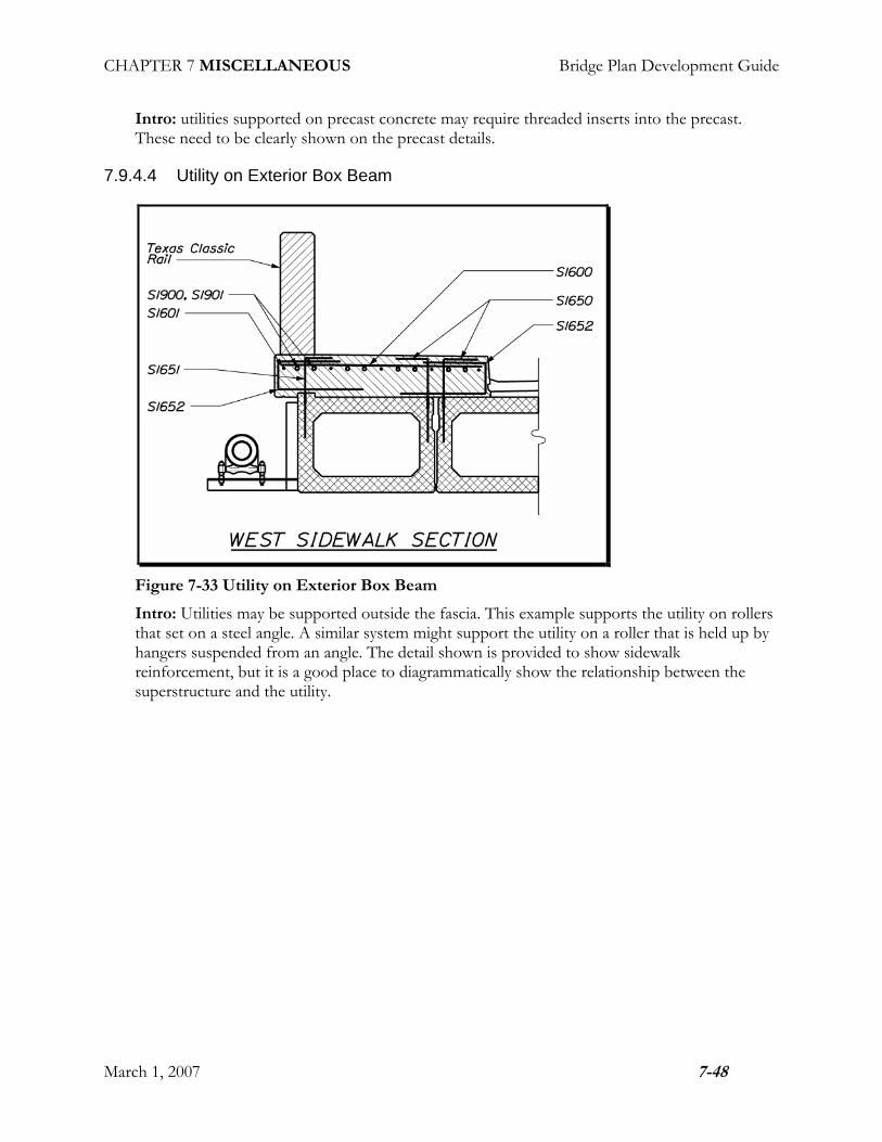
7.9.4.4 Utility on Exterior Box Beam
Figure 7-33 Utility on Exterior Box Beam
Intro: Utilities may be supported outside the fascia. This example supports the utility on rollers that set on a steel angle. A similar system might support the utility on a roller that is held up by hangers suspended from an angle. The detail shown is provided to show sidewalk reinforcement, but it is a good place to diagrammatically show the relationship between the superstructure and the utility.

CHAPTER 7 MISCELLANEOUS Bridge Plan Development Guide
March 1, 2007 7-49
7.9.4.5 Utility Penetrating Abutment
Figure 7-34 Utility Penetrating Abutment
Intro: the utility penetration through the abutment needs to be shown on the abutment elevation. Show and label any required sleeves, dimension the centerline of sleeve and label the elevation of the bottom of the sleeve. Reinforcing steel needs to be added around any penetrations to compensate for steel that is cut to make room for the utility.

CHAPTER 7 MISCELLANEOUS Bridge Plan Development Guide
March 1, 2007 7-50
7.10 Addendums to the Plans
7.10.1 Introduction
Occasionally revisions need to be made to the plans after the contract has been advertised. Typically this happens when one of the bidders brings a concern about the plans to the Project Manager. Sometimes the problem can be remedied by an addendum to the contract book. Other times the change needs to be on the plans. When this happens, the addendum needs to be tracked. This is done by numbering and dating the addendum.
7.10.2 Typical Sheet Names and Contents
Create a duplicate of the sheet that is to be revised. (Keep the original sheet for future reference.) The new file name should reflect the addendum revision number. The new sheet designation can be made by adding a letter suffix to the original sheet number. (If the original sheet was number 3, then the revised sheet will be 3A.) The new sheet will usually contain the original information that still pertains, with the revisions shown in addition.
Figure 7-35 Addendum Sheet
7.10.3 Detailing
Put the addendum number in a triangle (approximately ¼” high) next to the new/revised detail or dimension. To bring attention to the revision, draw a cloud around it. Create a revision block next to the sheets title block. The revision block shall contain the revision number, the date, the

CHAPTER 7 MISCELLANEOUS Bridge Plan Development Guide
March 1, 2007 7-51
initials of the project manager, the designer, the technician and a description of what was changed.
Figure 7-36 Revision Block
The revised sheet will need to be distributed to all of the bidders and filed with the original plans.

CHAPTER 7 MISCELLANEOUS Bridge Plan Development Guide
March 1, 2007 7-52
7.11 Hearing Plans
7.11.1 Introduction
Hearing plans are essentially a form of preliminary plans that have been enhanced (colored) for the public participation process. There are three types of public hearings, the informational hearing, the preliminary hearing, and the formal hearing. The preliminary and formal hearings are standard fare. The informational hearings happen less frequently.
Hearing plans on ordinary projects will be the responsibility of the team in the Bridge Program. Special projects such as extra large projects, photographic displays, animated or aerial displays may be done by the Office of Communications.
Figure 7-37 Hearing Plan
7.11.2 Prerequisites
To begin developing the Preliminary Public Hearing Plan the detailer needs the following:
1. Survey
2. Location Map
To begin developing the Formal Public Hearing Plans the detailer needs the following:
1. Proposed Plan
2. Proposed Profile
3. Typical Existing Bridge Section
4. Typical Proposed Bridge Section
5. Typical Proposed Approach Section
6. Location Map
CHAPTER 7 MISCELLANEOUS Bridge Plan Development Guide
March 1, 2007 7-53
7. Staged Construction Sequence (when appropriate)
8. Title Block Information
7.11.3 Detailing
The enhancement of the preliminary plans for public meeting consists of coloring the plans using the MaineDOT standard hearing plan colors, making some of the key text bold so that it is readable from a distance by people at the public meeting, and attaching the details to a backing for display at the meeting. Be sure to show all limits and impacts on your plan so that all interested parties at the public meeting can view what applies to them. Refer to the approach plan section of this guide for a detailed list.
7.11.3.1 Bold Text
Here is a list of text that should be bold.
1. Titles
2. Road Name/Route Number
3. To Town Name
4. Waterway Name
5. Title Block Information
6. Any other special item that needs to stand out
7.11.3.2 Color Reference
Use the following charts to reference when coloring the details. They are broken into three categories, plan, profile and typical sections.

CHAPTER 7 MISCELLANEOUS Bridge Plan Development Guide
March 1, 2007 7-54
Figure 7-38 Color Chart for Plan View

CHAPTER 7 MISCELLANEOUS Bridge Plan Development Guide
March 1, 2007 7-55
Figure 7-39 Color Chart for Profile

CHAPTER 7 MISCELLANEOUS Bridge Plan Development Guide
March 1, 2007 7-56
Figure 7-40 Color Chart for Sections

CHAPTER 7 MISCELLANEOUS Bridge Plan Development Guide
March 1, 2007 7-57
7.11.3.3 Background Sheet
Hearing plan details are displayed on a plain white paper background sheet. Details can be all printed on one sheet, or printed separately and then taped onto the background. This way if there is a small error on one detail, one does not have to plot out another long sheet to fix it. If there is room on the sheet, place the plan directly over the profile so that the viewer can see the relationship between the two. The title block is usually placed in the lower right hand corner. The other details can be placed wherever they fit best.
Any plans or display that goes to a public hearing becomes a legal document that must be electronically archived for six years. If the plans are written on at the public meeting, the hard copy must be scanned and archived.
7.11.4 References and Resources
MaineDOT Microstation Manual
CADD Cell Library and Settings Manager
H:\$Common-Bridge\Technician Tools
Office of Communication – Hearing Plan Specialists

CHAPTER 7 MISCELLANEOUS Bridge Plan Development Guide
March 1, 2007 7-58
7.12 Coast Guard Permitting