Embed Size (px)
Citation preview
Chapter 7
Settlement of Shallow Foundations
Omitted parts: Section 7.7
CAUSES OF SETTLEMENT
Settlement of a structure resting on soil may be caused by two distinct kinds of action within the foundation soils:-
I. Settlement Due to Shear Stress (Distortion Settlement) In the case the applied load caused shearing stresses to develop within the soil mass which are greater than the shear strength of the material, then the soil fails by sliding downward and laterally, and the structure settle and may tip of vertical alignment. This is what we referred to as BEARING CAPACITY.
II. Settlement Due to Compressive Stress (Volumetric Settlement) As a result of the applied load a compressive stress is transmitted to the soil leading to compressive strain. Due to the compressive strain the structure settles. This is important only if the settlement is excessive otherwise it is not dangerous.
ALLOWABLE BEARING CAPACITY
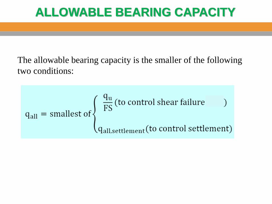
The allowable bearing capacity is the smaller of the following two conditions:
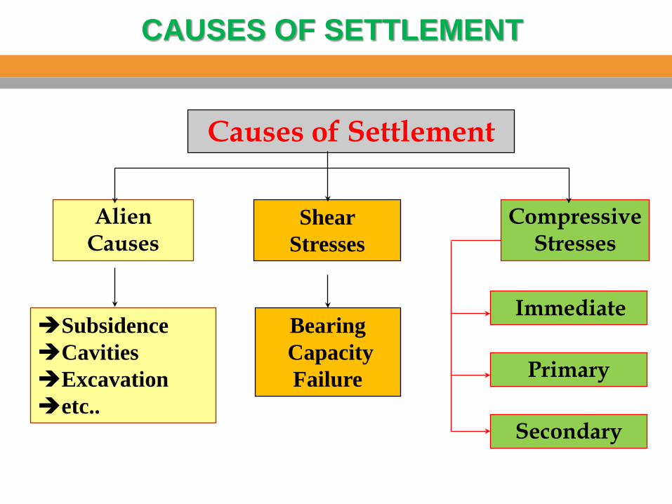
Causes of Settlement
Secondary
Primary
Immediate
Alien Causes
Subsidence Cavities Excavation etc..
Compressive Stresses
Shear Stresses
Bearing Capacity Failure
CAUSES OF SETTLEMENT
Mechanisms of Compression
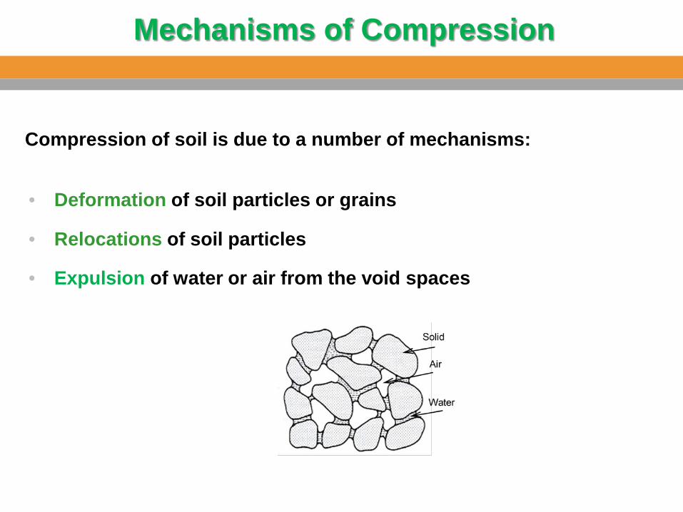
Compression of soil is due to a number of mechanisms:
• Deformation of soil particles or grains
• Relocations of soil particles
• Expulsion of water or air from the void spaces
Components of Settlement
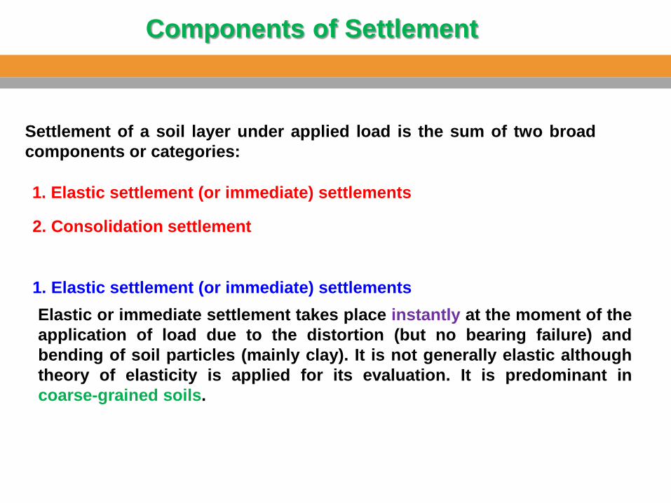
Settlement of a soil layer under applied load is the sum of two broad components or categories:
Elastic or immediate settlement takes place instantly at the moment of the application of load due to the distortion (but no bearing failure) and bending of soil particles (mainly clay). It is not generally elastic although theory of elasticity is applied for its evaluation. It is predominant in coarse-grained soils.
1. Elastic settlement (or immediate) settlements
2. Consolidation settlement
1. Elastic settlement (or immediate) settlements
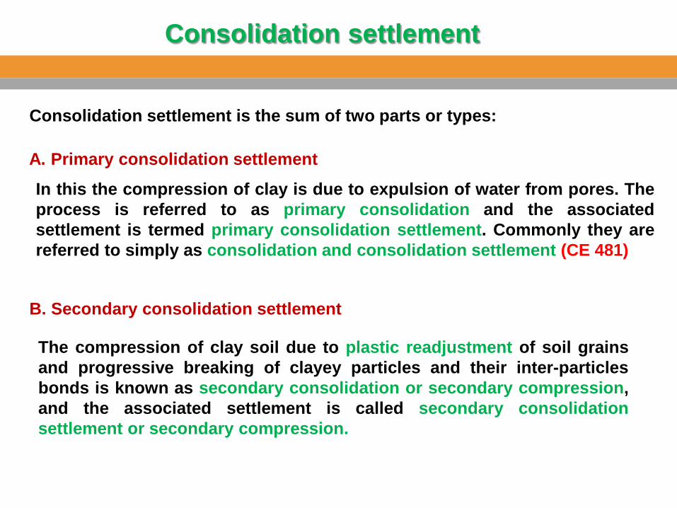
Consolidation settlement is the sum of two parts or types:
A. Primary consolidation settlement
In this the compression of clay is due to expulsion of water from pores. The process is referred to as primary consolidation and the associated settlement is termed primary consolidation settlement. Commonly they are referred to simply as consolidation and consolidation settlement (CE 481)
B. Secondary consolidation settlement
The compression of clay soil due to plastic readjustment of soil grains and progressive breaking of clayey particles and their inter-particles bonds is known as secondary consolidation or secondary compression, and the associated settlement is called secondary consolidation settlement or secondary compression.
Consolidation settlement
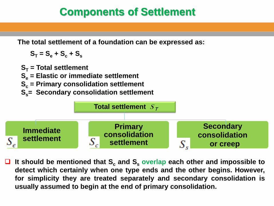
ST = Total settlement
Se = Elastic or immediate settlement Sc = Primary consolidation settlement Ss= Secondary consolidation settlement
The total settlement of a foundation can be expressed as: ST = Se + Sc + Ss
Immediate settlement
Primary consolidation
settlement
Secondary consolidation
or creep
Total settlement S T
It should be mentioned that Sc and Ss overlap each other and impossible to detect which certainly when one type ends and the other begins. However, for simplicity they are treated separately and secondary consolidation is usually assumed to begin at the end of primary consolidation.
Components of Settlement
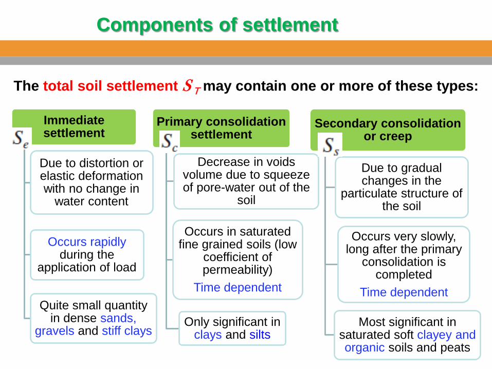
The total soil settlement S T may contain one or more of these types:
Immediate settlement
Due to distortion or elastic deformation with no change in
water content
Occurs rapidly during the
application of load
Quite small quantity in dense sands,
gravels and stiff clays
Primary consolidation settlement
Decrease in voids volume due to squeeze of pore-water out of the
soil
Occurs in saturated fine grained soils (low
coefficient of permeability)
Time dependent
Only significant in clays and silts
Secondary consolidation or creep
Due to gradual changes in the
particulate structure of the soil
Occurs very slowly, long after the primary
consolidation is completed
Time dependent
Most significant in saturated soft clayey and organic soils and peats
Components of settlement
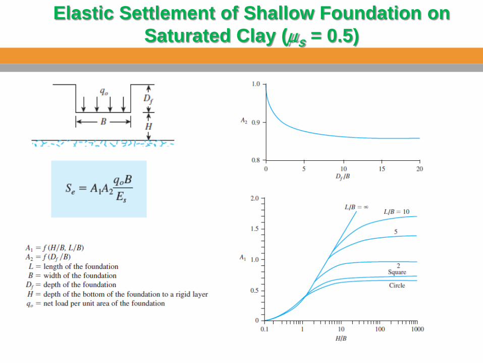
Elastic Settlement of Shallow Foundation on Saturated Clay (µs = 0.5)
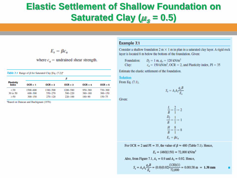
Elastic Settlement of Shallow Foundation on Saturated Clay (µs = 0.5)
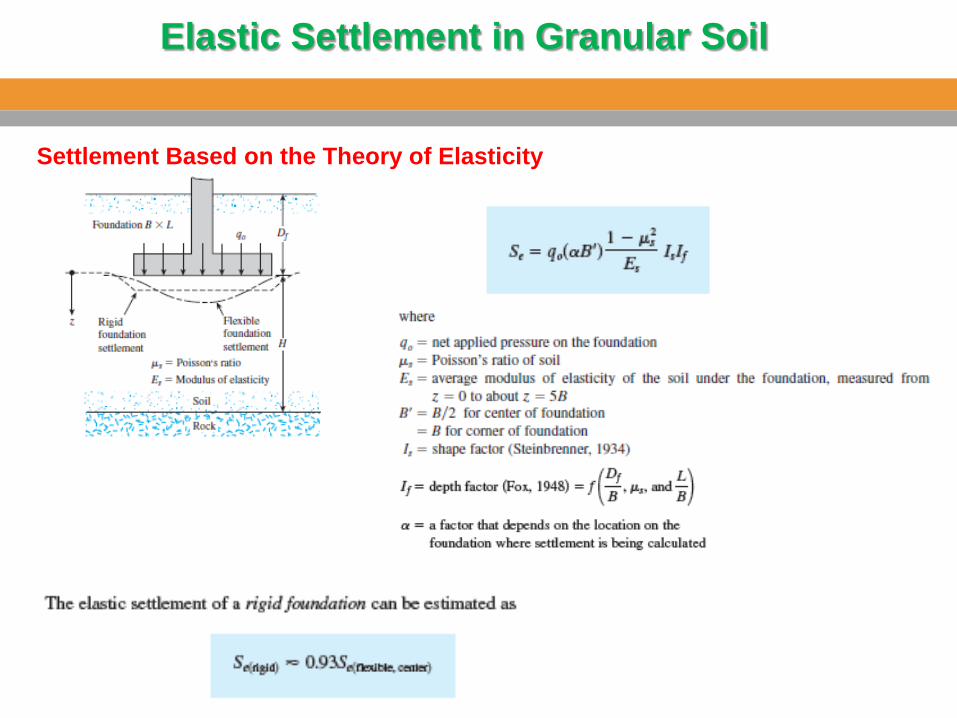
Elastic Settlement in Granular Soil
Settlement Based on the Theory of Elasticity
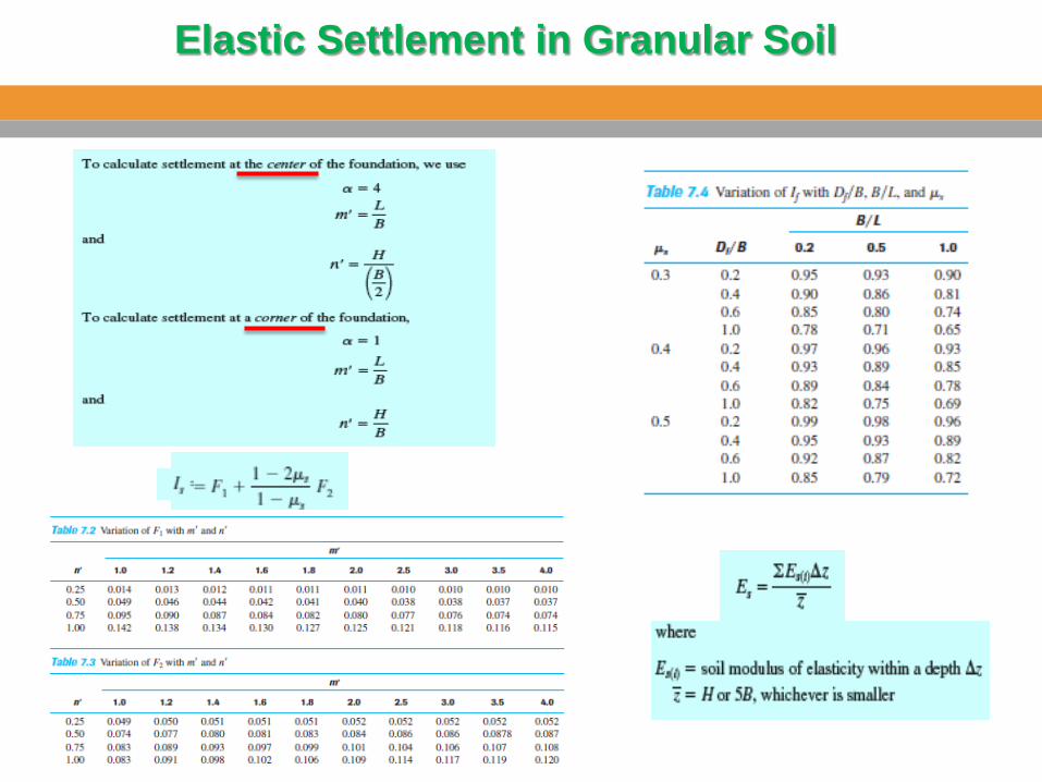
Elastic Settlement in Granular Soil
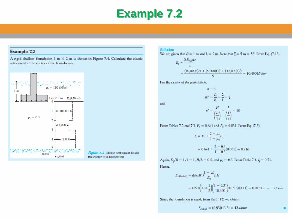
Example 7.2
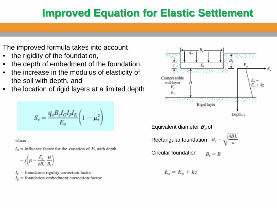
Improved Equation for Elastic Settlement
Equivalent diameter Be of Rectangular foundation Circular foundation
The improved formula takes into account • the rigidity of the foundation, • the depth of embedment of the foundation, • the increase in the modulus of elasticity of
the soil with depth, and • the location of rigid layers at a limited depth
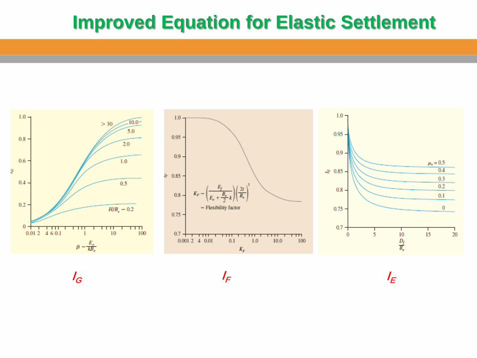
IG IF IE
Improved Equation for Elastic Settlement
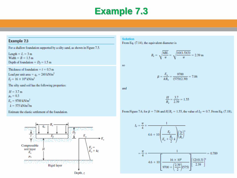
Example 7.3
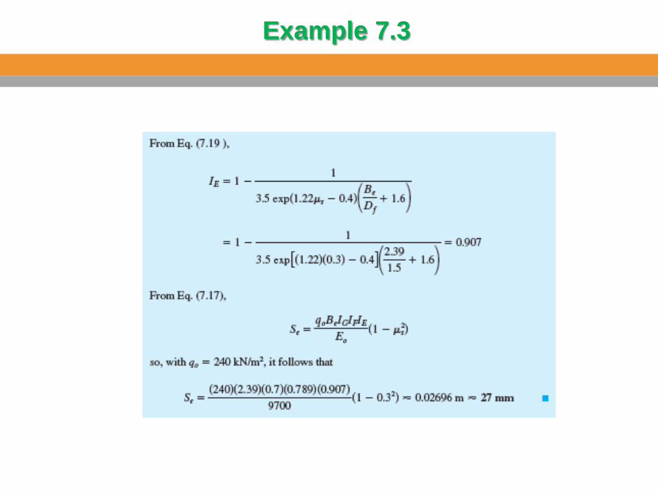
Example 7.3
Settlement of Sandy Soil: Use of Strain Influence Factor
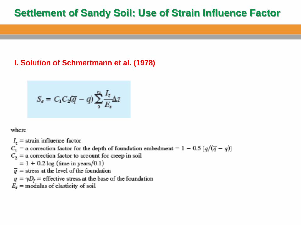
I. Solution of Schmertmann et al. (1978)
Settlement of Sandy Soil: Use of Strain Influence Factor
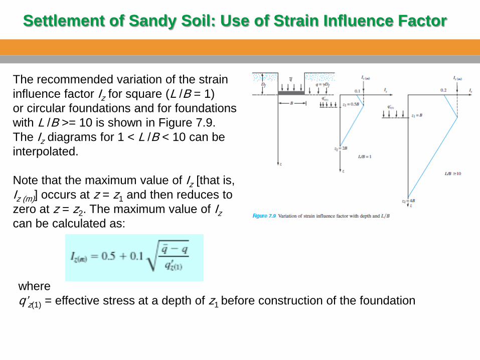
The recommended variation of the strain influence factor Iz for square (L /B = 1) or circular foundations and for foundations with L /B >= 10 is shown in Figure 7.9. The Iz diagrams for 1 < L /B < 10 can be interpolated. Note that the maximum value of Iz [that is, Iz (m)] occurs at z = z1 and then reduces to zero at z = z2. The maximum value of Iz can be calculated as:
where q’z(1) = effective stress at a depth of z1 before construction of the foundation
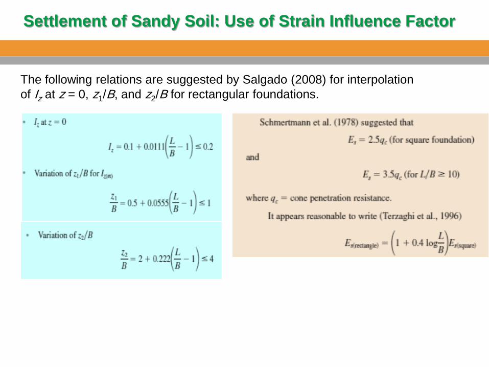
The following relations are suggested by Salgado (2008) for interpolation of Iz at z = 0, z1/B, and z2/B for rectangular foundations.
Settlement of Sandy Soil: Use of Strain Influence Factor
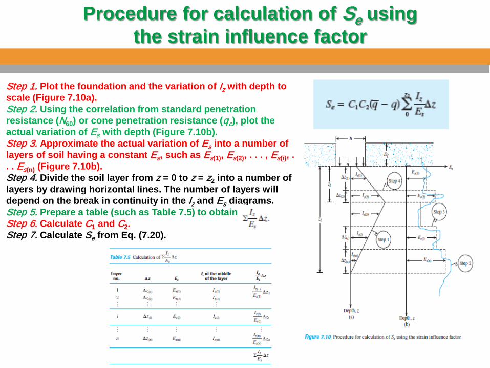
Step 1. Plot the foundation and the variation of Iz with depth to scale (Figure 7.10a). Step 2. Using the correlation from standard penetration resistance (N60) or cone penetration resistance (qc), plot the actual variation of Es with depth (Figure 7.10b). Step 3. Approximate the actual variation of Es into a number of layers of soil having a constant Es, such as Es(1), Es(2), . . . , Es(i), . . . Es(n) (Figure 7.10b). Step 4. Divide the soil layer from z = 0 to z = z2 into a number of layers by drawing horizontal lines. The number of layers will depend on the break in continuity in the Iz and Es diagrams. Step 5. Prepare a table (such as Table 7.5) to obtain Step 6. Calculate C1 and C2. Step 7. Calculate Se from Eq. (7.20).
Procedure for calculation of Se using the strain influence factor
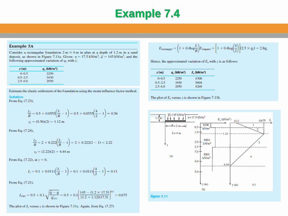
Example 7.4
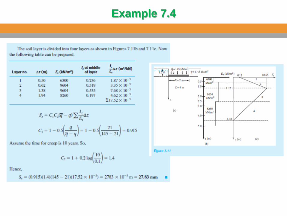
Example 7.4
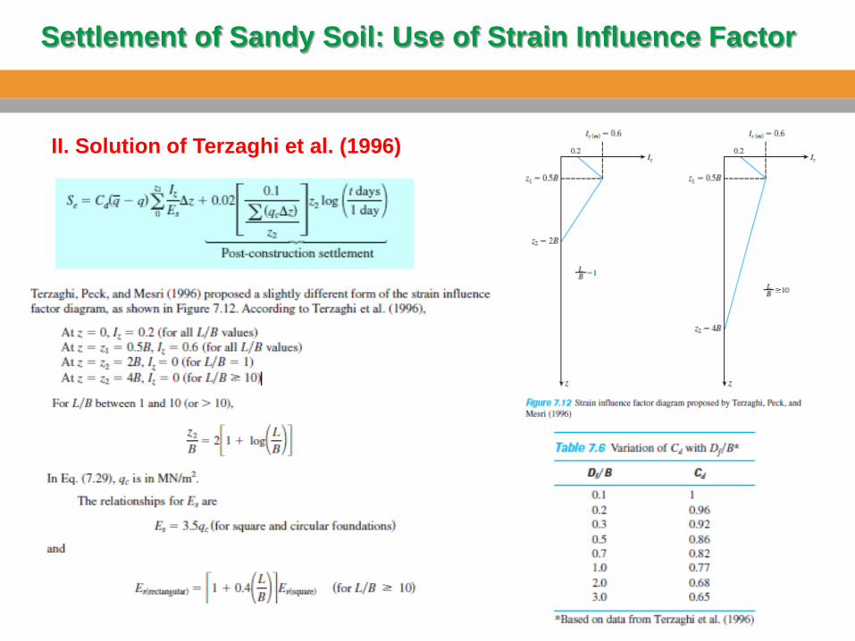
II. Solution of Terzaghi et al. (1996)
Settlement of Sandy Soil: Use of Strain Influence Factor
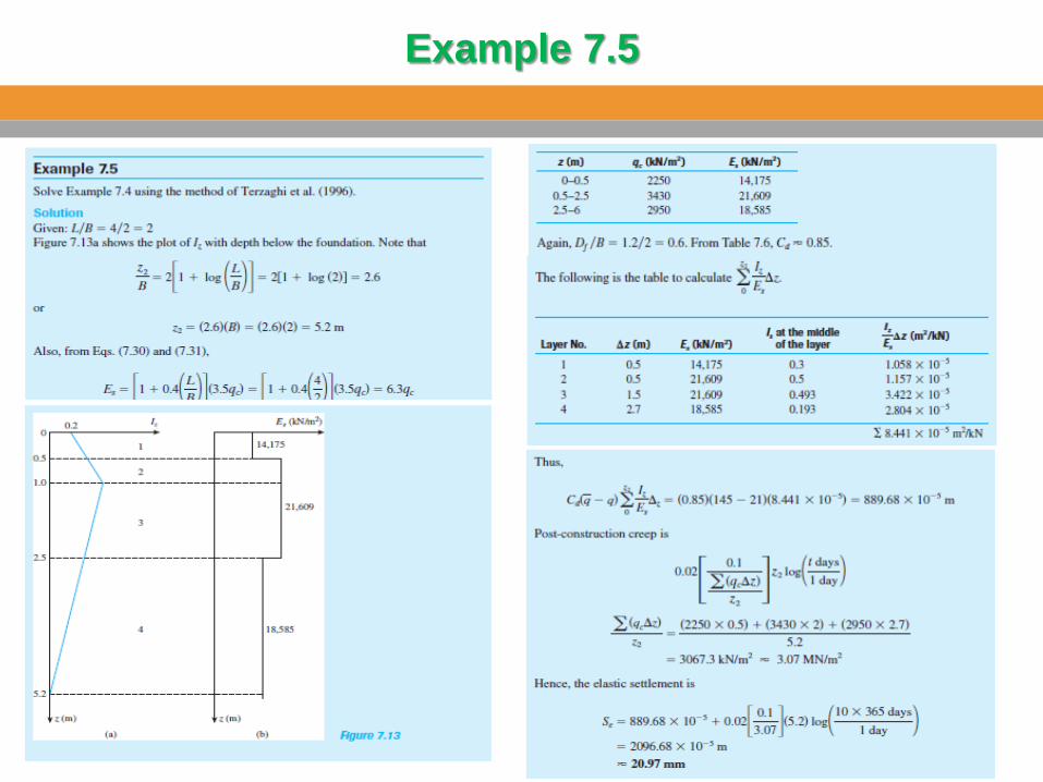
Example 7.5
Example 7.5
Settlement of Foundation on Sand Based on Standard Penetration Resistance
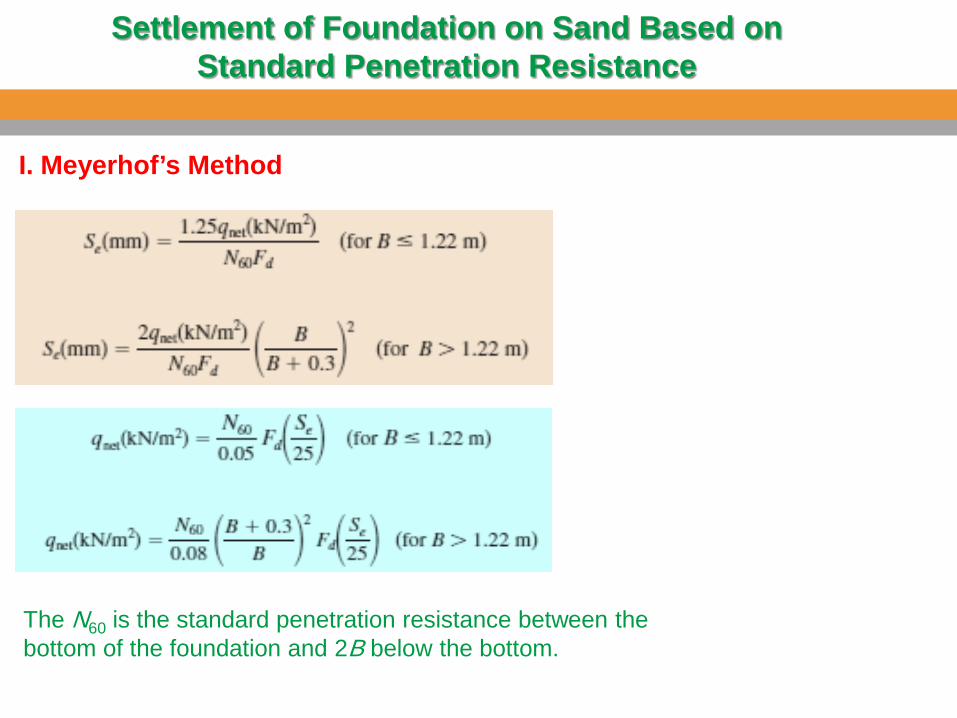
I. Meyerhof’s Method
The N60 is the standard penetration resistance between the bottom of the foundation and 2B below the bottom.
Settlement of Foundation on Sand Based on Standard Penetration Resistance
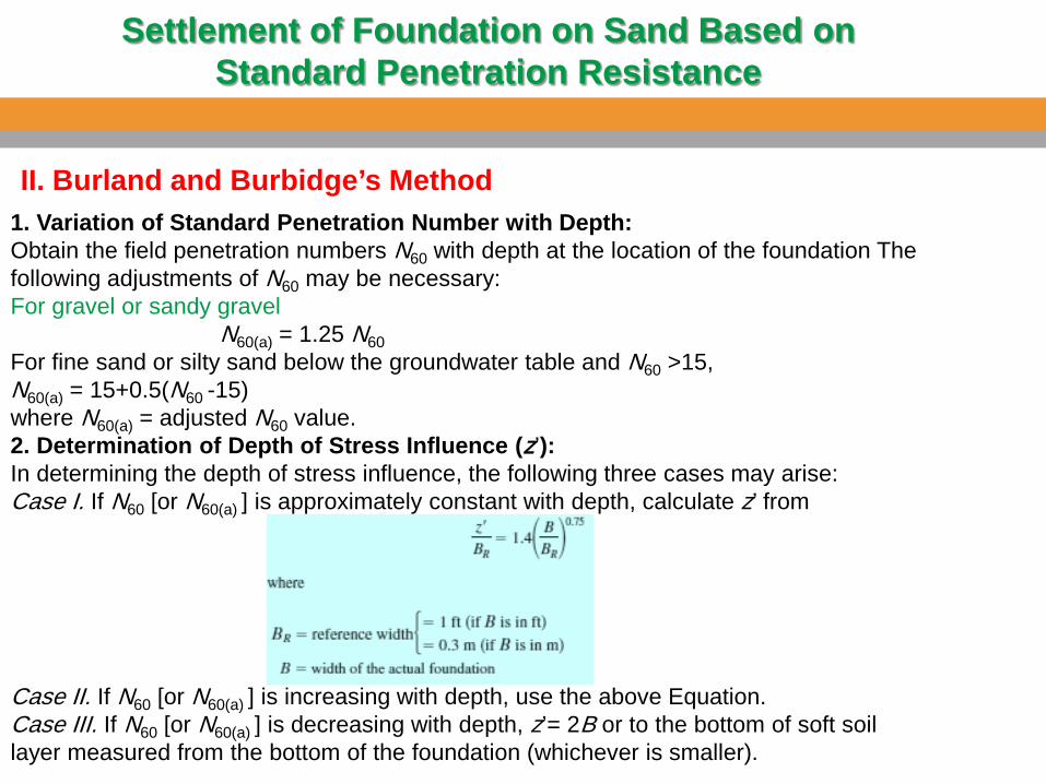
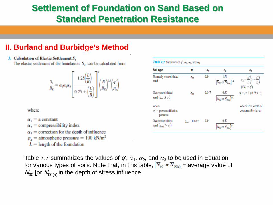
II. Burland and Burbidge’s Method 1. Variation of Standard Penetration Number with Depth: Obtain the field penetration numbers N60 with depth at the location of the foundation The following adjustments of N60 may be necessary: For gravel or sandy gravel N60(a) = 1.25 N60 For fine sand or silty sand below the groundwater table and N60 >15, N60(a) = 15+0.5(N60 -15) where N60(a) = adjusted N60 value. 2. Determination of Depth of Stress Influence (z’): In determining the depth of stress influence, the following three cases may arise: Case I. If N60 [or N60(a) ] is approximately constant with depth, calculate z’ from Case II. If N60 [or N60(a) ] is increasing with depth, use the above Equation. Case III. If N60 [or N60(a) ] is decreasing with depth, z’= 2B or to the bottom of soft soil layer measured from the bottom of the foundation (whichever is smaller).
Settlement of Foundation on Sand Based on Standard Penetration Resistance
II. Burland and Burbidge’s Method
Table 7.7 summarizes the values of q’, α1, α2, and α3 to be used in Equation for various types of soils. Note that, in this table, = average value of N60 [or N60(a) in the depth of stress influence.
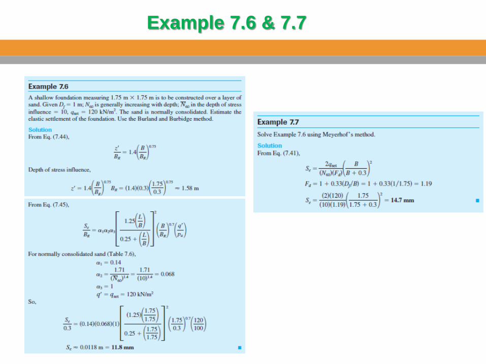
Example 7.6 & 7.7
Effect of the Rise of Water Table on Elastic Settlement
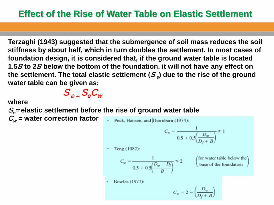
Terzaghi (1943) suggested that the submergence of soil mass reduces the soil stiffness by about half, which in turn doubles the settlement. In most cases of foundation design, it is considered that, if the ground water table is located 1.5B to 2B below the bottom of the foundation, it will not have any effect on the settlement. The total elastic settlement (S’
e) due to the rise of the ground water table can be given as: S’
e = SeCw where Se= elastic settlement before the rise of ground water table Cw = water correction factor
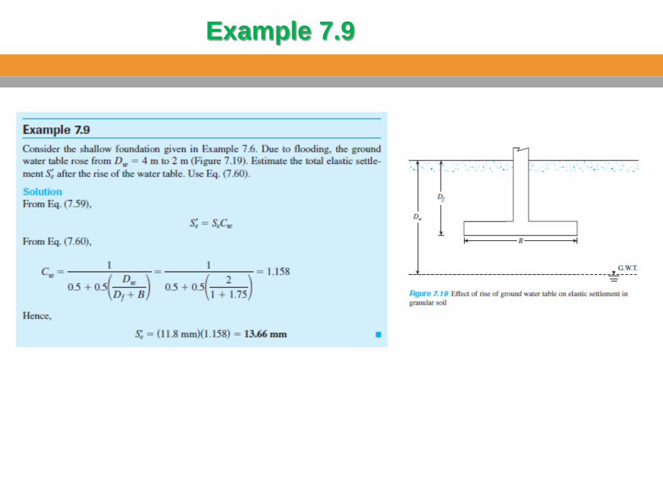
Example 7.9
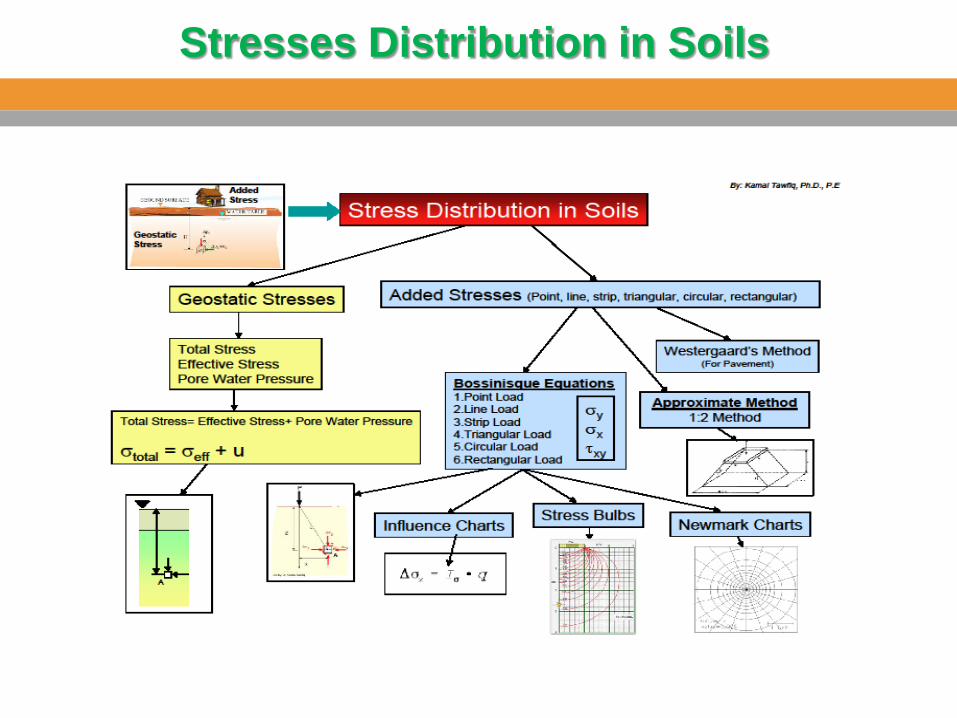
Stresses Distribution in Soils
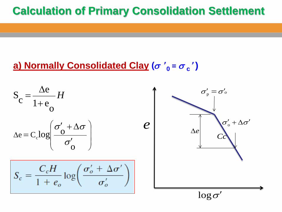
Calculation of Primary Consolidation Settlement
) ’cσ = 0 ’σ ( a) Normally Consolidated Clay
Hoe1
ecS
+∆=
∆
′
∆+′=
o
ologcCeσ
σσ
oσσ ′′ =p
σσ ′∆+′oe∆
σ ′log
eCc
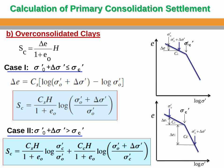
Calculation of Primary Consolidation Settlement
pσ ′σσ ′∆+′o
e∆
σ ′log
esC
oσ ′
Hoe1
ecS
+∆=
b) Overconsolidated Clays
σ ’0 +∆σ ’ ≤ σ c’ Case I:
σσ ′∆+′o2e∆
σ ′log
e
Cc
oσ ′
1e∆sC
σ c’
σ ’0 +∆σ ’ > σ c’ Case II:
σ c’
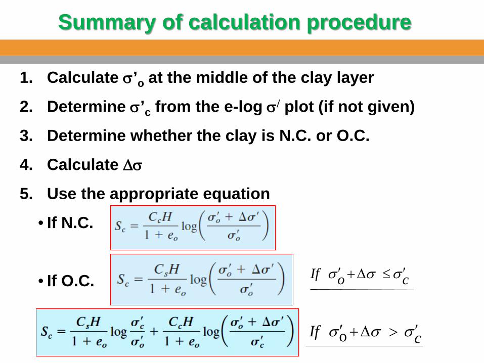
Summary of calculation procedure
1. Calculate σ’o at the middle of the clay layer
2. Determine σ’c from the e-log σ/ plot (if not given)
3. Determine whether the clay is N.C. or O.C.
4. Calculate ∆σ
5. Use the appropriate equation
• If N.C.
• If O.C.
cIf σσσ ′>∆+′ o
coIf σσσ ′≤∆+′
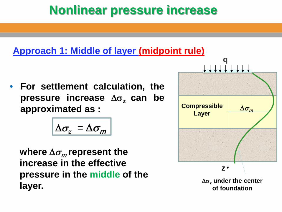
• For settlement calculation, the pressure increase ∆σz can be approximated as :
q
z
where ∆σm represent the increase in the effective pressure in the middle of the layer.
Compressible Layer
∆σz under the center of foundation
Approach 1: Middle of layer (midpoint rule)
∆σz = ∆σm
Nonlinear pressure increase
∆σm
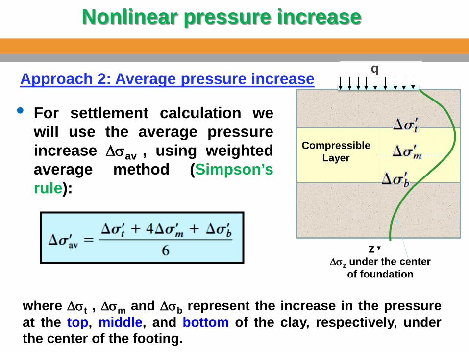
• For settlement calculation we will use the average pressure increase ∆σav , using weighted average method (Simpson’s rule):
q
z
Compressible Layer
∆σz under the center of foundation
Approach 2: Average pressure increase
where ∆σt , ∆σm and ∆σb represent the increase in the pressure at the top, middle, and bottom of the clay, respectively, under the center of the footing.
Nonlinear pressure increase
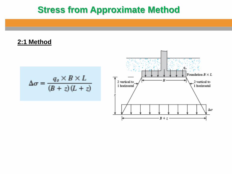
Stress from Approximate Method
2:1 Method
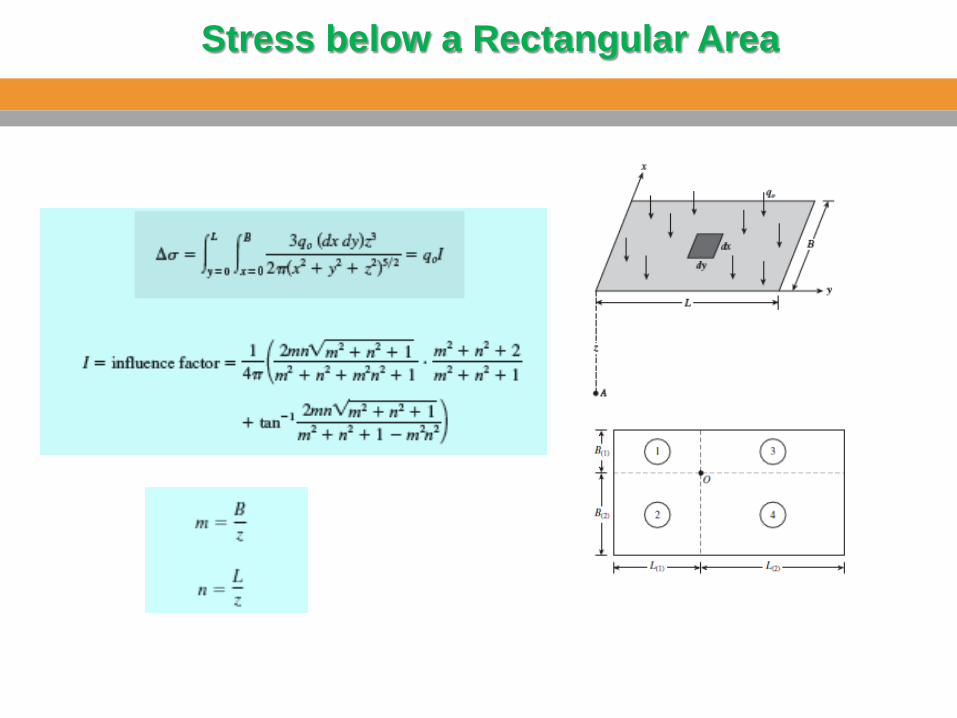
Stress below a Rectangular Area
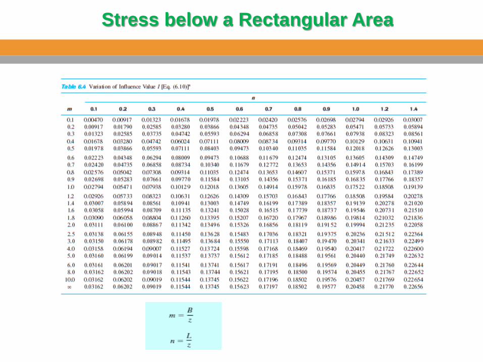
Stress below a Rectangular Area
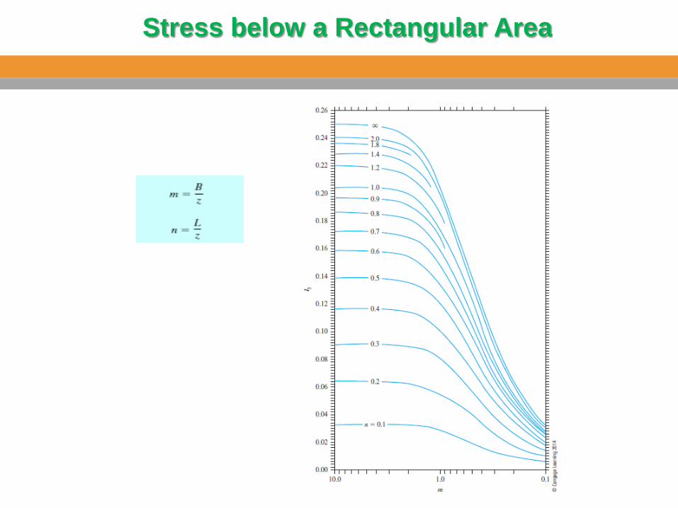
Stress below a Rectangular Area
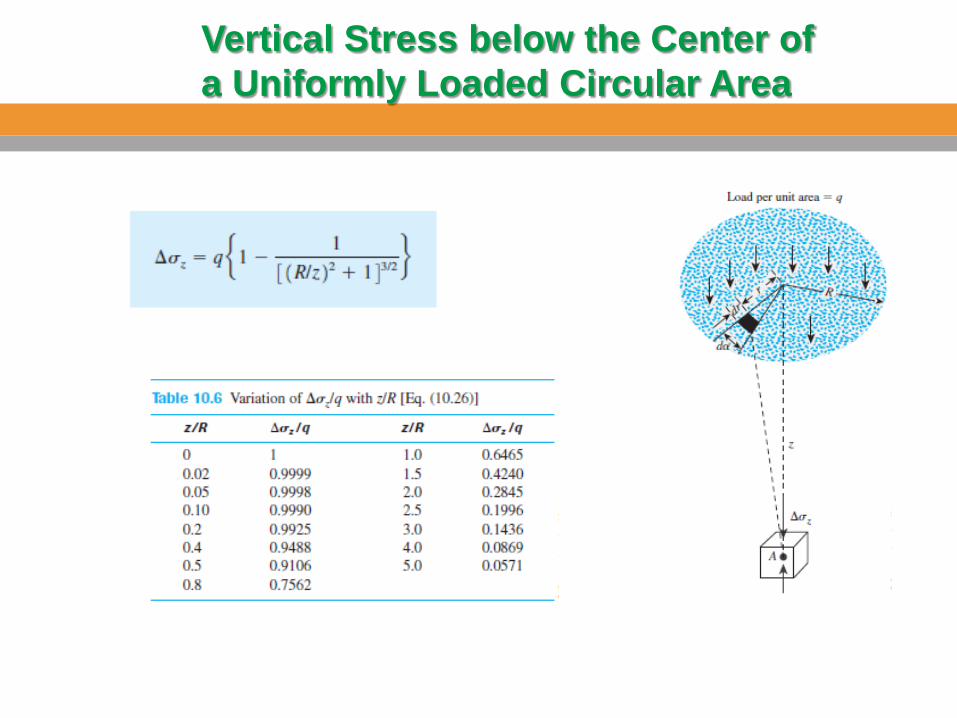
Vertical Stress below the Center of a Uniformly Loaded Circular Area
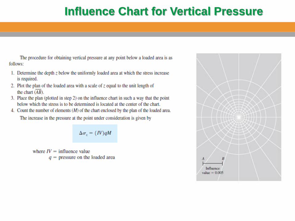
Influence Chart for Vertical Pressure
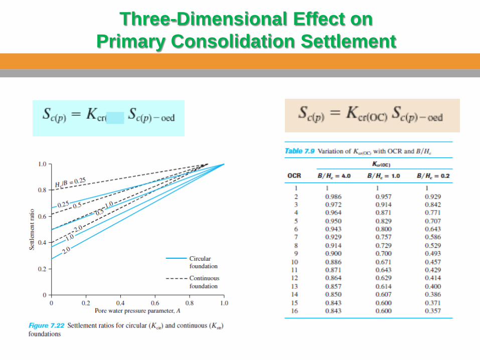
Three-Dimensional Effect on Primary Consolidation Settlement
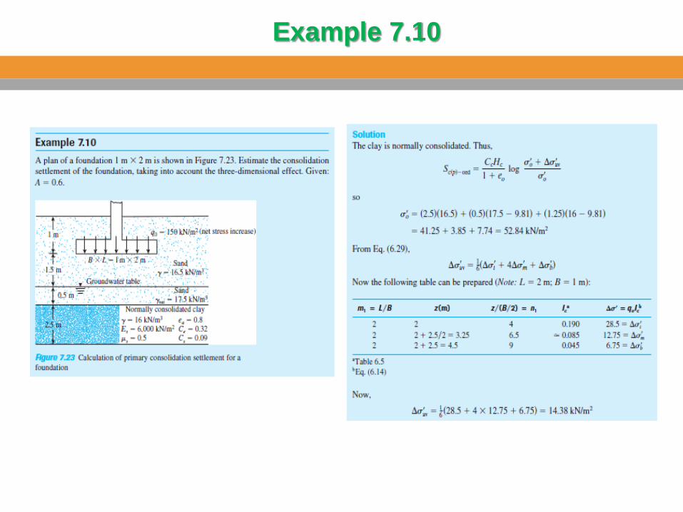
Example 7.10
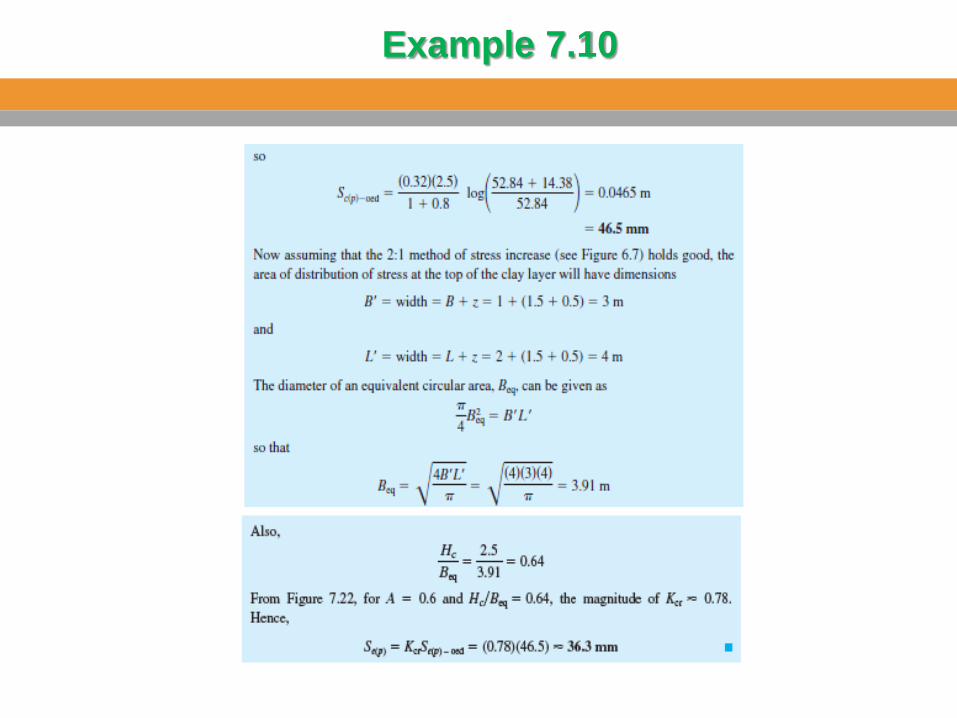
Example 7.10
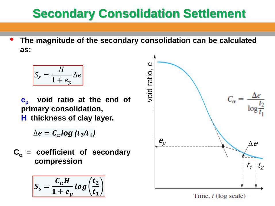
Secondary Consolidation Settlement
• The magnitude of the secondary consolidation can be calculated as:
void
rat
io, e
t1 t2
∆e ep
ep void ratio at the end of primary consolidation, H thickness of clay layer.
Cα = coefficient of secondary compression
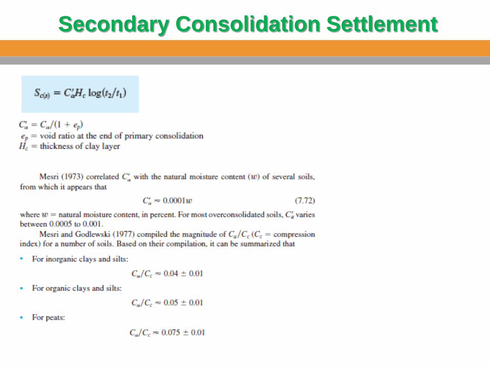
Secondary Consolidation Settlement
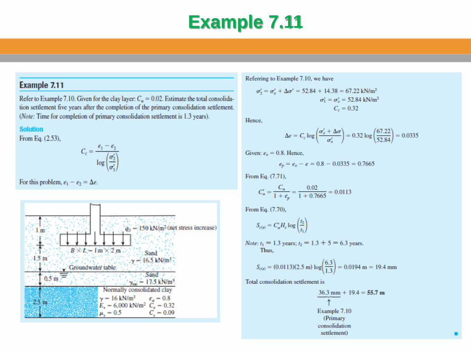
Example 7.11
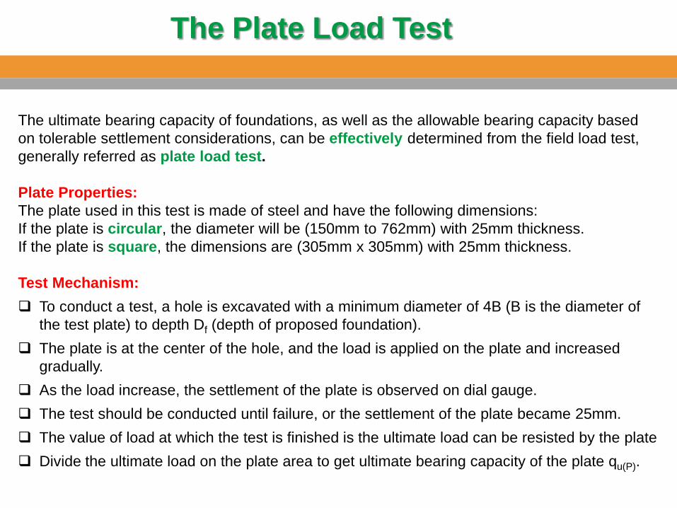
The ultimate bearing capacity of foundations, as well as the allowable bearing capacity based on tolerable settlement considerations, can be effectively determined from the field load test, generally referred as plate load test. Plate Properties: The plate used in this test is made of steel and have the following dimensions: If the plate is circular, the diameter will be (150mm to 762mm) with 25mm thickness. If the plate is square, the dimensions are (305mm x 305mm) with 25mm thickness. Test Mechanism: To conduct a test, a hole is excavated with a minimum diameter of 4B (B is the diameter of
the test plate) to depth Df (depth of proposed foundation). The plate is at the center of the hole, and the load is applied on the plate and increased
gradually. As the load increase, the settlement of the plate is observed on dial gauge. The test should be conducted until failure, or the settlement of the plate became 25mm. The value of load at which the test is finished is the ultimate load can be resisted by the plate Divide the ultimate load on the plate area to get ultimate bearing capacity of the plate qu(P).
The Plate Load Test
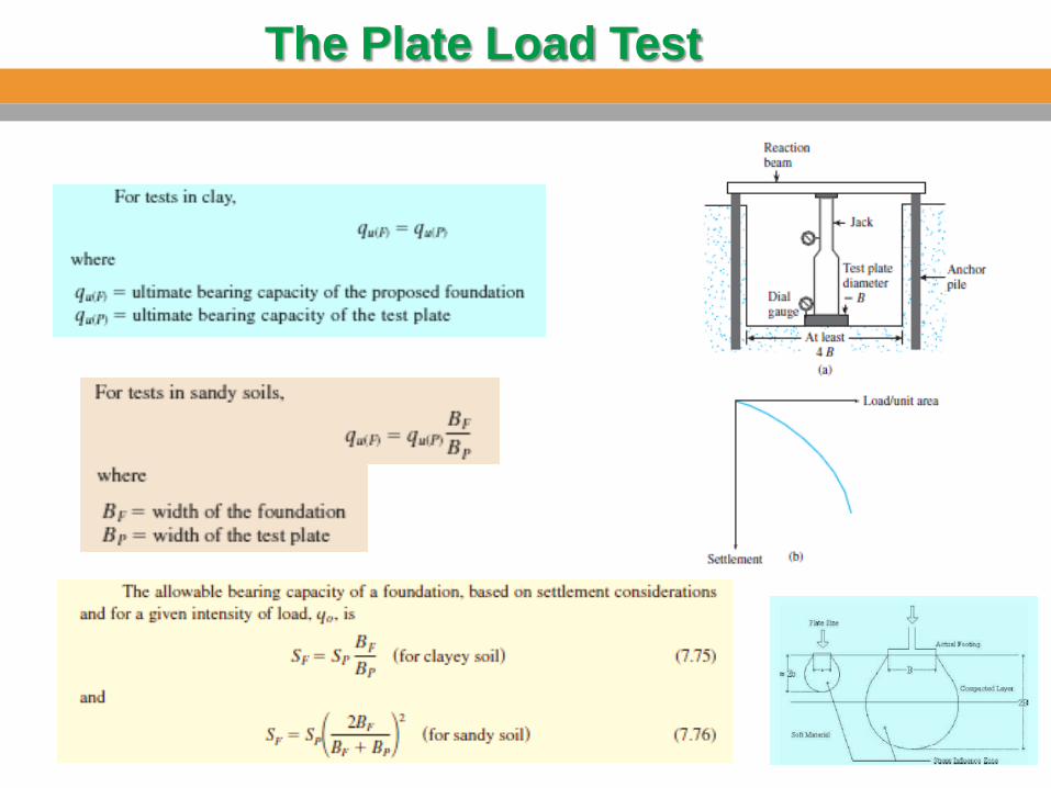
The Plate Load Test
Presumptive Bearing Capacity
Building Codes Tolerable Settlement of Buildings