Embed Size (px)
Citation preview
BEARING CAPACITYANALYSES FOREARTHQUAKES
The following notation is used in this chapter:
SYMBOL DEFINITION
B Width of footingB′ Reduced footing width to account for eccentricity of loadc Cohesion based on total stress analysisc′ Cohesion based on effective stress analysisDf Depth below ground surface to bottom of footingDr Relative densitye Eccentricity of vertical load Qe1, e2 Eccentricities along and across footing (Fig. 8.9)FS Factor of safetyH1 Thickness of surface layer that does not liquefyk0 Coefficient of earth pressure at restL Length of footingL′ Reduced footing length to account for eccentricity of loadN Measured SPT blow count (N value in blows per foot)Nc, N�, Nq Dimensionless bearing capacity factors(N1)60 N value corrected for field testing procedures and overburden pressureP, Q Footing loadqall Allowable bearing pressureqult Ultimate bearing capacityq′ Largest bearing pressure exerted by eccentrically loaded footingq″ Lowest bearing pressure exerted by eccentrically loaded footingQult Load causing a bearing capacity failureru Pore water pressure ratioR Shear resistance of soilsu Undrained shear strength of soilSt Sensitivity of soilT Vertical distance from bottom of footing to top of liquefied soil layerue Excess pore water pressure generated during earthquakewl Liquid limitwp Plastic limit� Friction angle based on total stress analysis�′ Friction angle based on effective stress analysis�b Buoyant unit weight of saturated soil below groundwater table�t Total unit weight of soil
CHAPTER 8
8.1
Ch08_DAY 10/26/01 2:07 PM Page 8.1
�′ Initial effective stress acting on shear surface�h Horizontal total stress�h′ Horizontal effective stress�v Vertical total stress�vm′ Maximum past pressure, also known as preconsolidation pressure�v0′ Vertical effective stress�f Shear strength of soil
8.1 INTRODUCTION
8.1.1 General, Punching, and Local Shear
A bearing capacity failure is defined as a foundation failure that occurs when the shearstresses in the soil exceed the shear strength of the soil. For both the static and seismiccases, bearing capacity failures of foundations can be grouped into three categories, (Vesic1963, 1967, 1975):
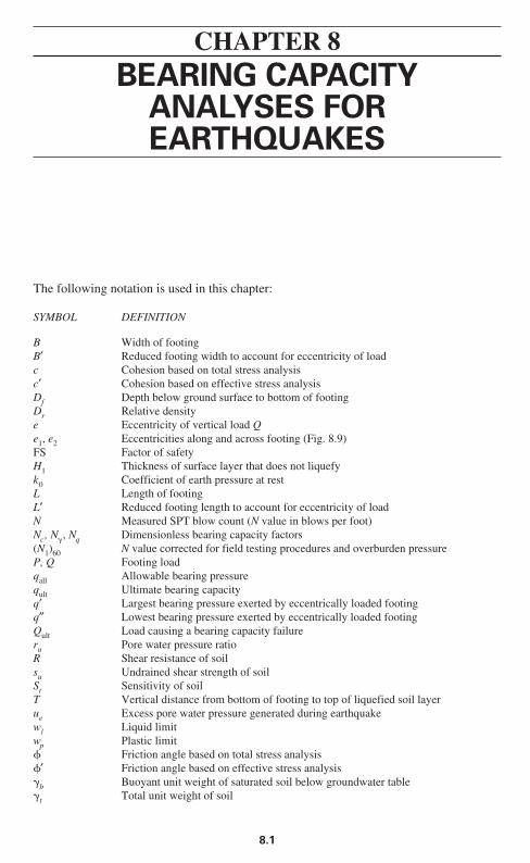
1. General shear (Fig. 8.1): As shown in Fig. 8.1, a general shear failure involvestotal rupture of the underlying soil. There is a continuous shear failure of the soil (solidlines) from below the footing to the ground surface. When the load is plotted versus settle-ment of the footing, there is a distinct load at which the foundation fails (solid circle), andthis is designated Qult. The value of Qult divided by the width B and length L of the footingis considered to be the ultimate bearing capacity qult of the footing. The ultimate bearingcapacity has been defined as the bearing stress that causes a sudden catastrophic failure ofthe foundation (Lambe and Whitman 1969).
Note in Fig. 8.1 that a general shear failure ruptures and pushes up the soil on both sidesof the footing. For actual failures in the field, the soil is often pushed up on only one sideof the footing with subsequent tilting of the structure. A general shear failure occurs forsoils that are in a dense or hard state.
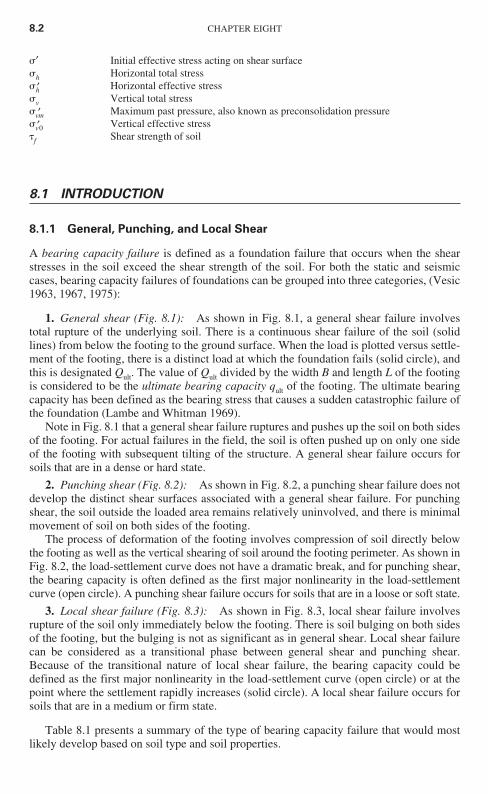
2. Punching shear (Fig. 8.2): As shown in Fig. 8.2, a punching shear failure does notdevelop the distinct shear surfaces associated with a general shear failure. For punchingshear, the soil outside the loaded area remains relatively uninvolved, and there is minimalmovement of soil on both sides of the footing.
The process of deformation of the footing involves compression of soil directly belowthe footing as well as the vertical shearing of soil around the footing perimeter. As shown inFig. 8.2, the load-settlement curve does not have a dramatic break, and for punching shear,the bearing capacity is often defined as the first major nonlinearity in the load-settlementcurve (open circle). A punching shear failure occurs for soils that are in a loose or soft state.
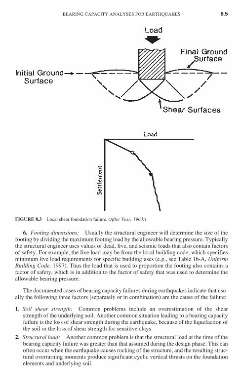
3. Local shear failure (Fig. 8.3): As shown in Fig. 8.3, local shear failure involvesrupture of the soil only immediately below the footing. There is soil bulging on both sidesof the footing, but the bulging is not as significant as in general shear. Local shear failurecan be considered as a transitional phase between general shear and punching shear.Because of the transitional nature of local shear failure, the bearing capacity could bedefined as the first major nonlinearity in the load-settlement curve (open circle) or at thepoint where the settlement rapidly increases (solid circle). A local shear failure occurs forsoils that are in a medium or firm state.
Table 8.1 presents a summary of the type of bearing capacity failure that would mostlikely develop based on soil type and soil properties.
8.2 CHAPTER EIGHT
Ch08_DAY 10/26/01 2:07 PM Page 8.2
8.1.2 Bearing Capacity Failures
Compared to the number of structures damaged by earthquake-induced settlement, thereare far fewer structures that have earthquake-induced bearing capacity failures. This isbecause of the following factors:
1. Settlement governs: The foundation design is based on several requirements. Twoof the main considerations are that (1) settlement due to the building loads must not exceedtolerable values and (2) there must be an adequate factor of safety against a bearing capac-ity failure. In most cases, settlement governs and the foundation bearing pressures recom-mended by the geotechnical engineer are based on limiting the amount of expectedsettlement due to the static or seismic cases. In other cases where the settlement is too high,the building is often constructed with a deep foundation, which also reduces the possibilityof a bearing capacity failure.
2. Extensive studies: There have been extensive studies of both static and seismicbearing capacity failures, which have led to the development of bearing capacity equationsthat are routinely used in practice to determine the ultimate bearing capacity of the foun-dation.
3. Factor of safety: To determine the allowable bearing pressure qall, the ultimatebearing capacity qult is divided by a factor of safety. The normal factor of safety used forstatic bearing capacity analyses is 3. For the evaluation of the bearing capacity for seismic
BEARING CAPACITY ANALYSES FOR EARTHQUAKES 8.3
FIGURE 8.1 General shear foundation failure. (After Vesic 1963.)
Ch08_DAY 10/26/01 2:07 PM Page 8.3
analysis, the factor of safety is often in the range of 5 to 10 (Krinitzsky et al. 1993). Theseare high factors of safety compared to other factors of safety, such as only 1.5 for slope sta-bility analyses (Chap. 9).
4. Minimum footing sizes: Building codes often require minimum footing sizes andembedment depths. Larger footing sizes will lower the bearing pressure on the soil andreduce the potential for static or seismic bearing capacity failures.
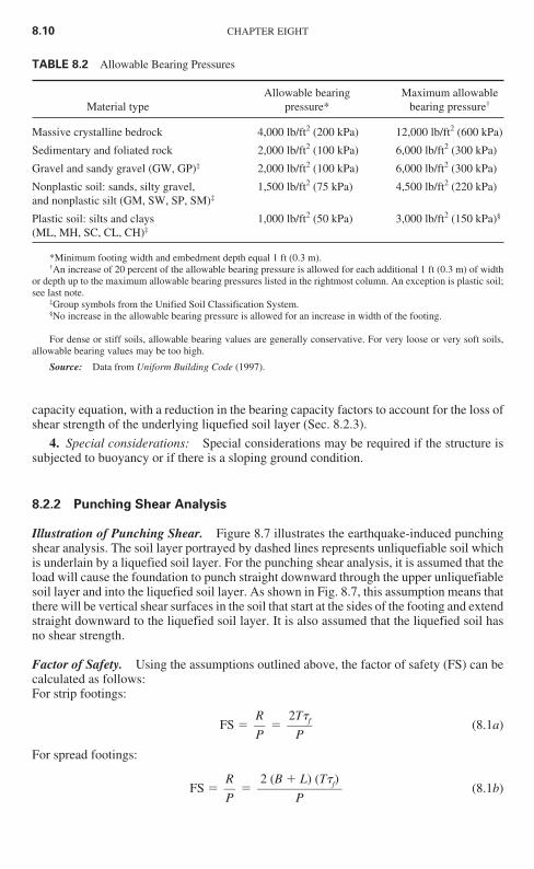
5. Allowable bearing pressures: In addition, building codes often have maximumallowable bearing pressures for different soil and rock conditions. Table 8.2 presents maxi-mum allowable bearing pressures based on the Uniform Building Code (Table 18-I-A, 1997).Especially in the case of dense or stiff soils, these allowable bearing pressures often have ade-quate factors of safety for both static and seismic cases.
8.4 CHAPTER EIGHT
FIGURE 8.2 Punching shear foundation failure. (After Vesic 1963.)
Ch08_DAY 10/26/01 2:07 PM Page 8.4
6. Footing dimensions: Usually the structural engineer will determine the size of thefooting by dividing the maximum footing load by the allowable bearing pressure. Typicallythe structural engineer uses values of dead, live, and seismic loads that also contain factorsof safety. For example, the live load may be from the local building code, which specifiesminimum live load requirements for specific building uses (e.g., see Table 16-A, UniformBuilding Code, 1997). Thus the load that is used to proportion the footing also contains afactor of safety, which is in addition to the factor of safety that was used to determine theallowable bearing pressure.
The documented cases of bearing capacity failures during earthquakes indicate that usu-ally the following three factors (separately or in combination) are the cause of the failure:
1. Soil shear strength: Common problems include an overestimation of the shearstrength of the underlying soil. Another common situation leading to a bearing capacityfailure is the loss of shear strength during the earthquake, because of the liquefaction ofthe soil or the loss of shear strength for sensitive clays.
2. Structural load: Another common problem is that the structural load at the time of thebearing capacity failure was greater than that assumed during the design phase. This canoften occur when the earthquake causes rocking of the structure, and the resulting struc-tural overturning moments produce significant cyclic vertical thrusts on the foundationelements and underlying soil.
BEARING CAPACITY ANALYSES FOR EARTHQUAKES 8.5
FIGURE 8.3 Local shear foundation failure. (After Vesic 1963.)
Ch08_DAY 10/26/01 2:07 PM Page 8.5
3. Change in site conditions: An altered site can produce a bearing capacity failure. Forexample, if the groundwater table rises, then the potential for liquefaction is increased.Another example is the construction of an adjacent excavation, which could result in areduction in support and a bearing capacity failure.
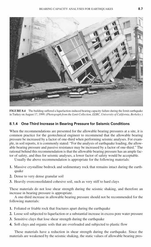
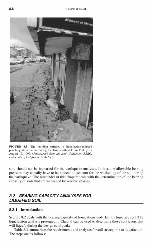
The most common cause of a seismic bearing capacity failure is liquefaction of theunderlying soil. Section 3.4.2 presents an introduction to bearing capacity failures causedby liquefaction during the earthquake. Figures 3.20 to 3.22 show examples of bearingcapacity failures caused by the Niigata earthquake on June 16, 1964. Figure 8.4 shows abearing capacity failure due to liquefaction during the Izmit earthquake in Turkey onAugust 17, 1999. Another example is shown in Fig. 8.5, where rather than falling over, thebuilding has literally punched downward into the liquefied soil.
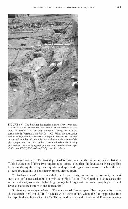
Although bearing capacity failures related to liquefaction of underlying soils are mostcommon, there could also be localized failures due to punching shear when the footing isoverloaded, such as by the building’s rocking back and forth. Figure 8.6 presents an exam-ple of a punching-type failure. The building foundation shown in Fig. 8.6 was constructedof individual spread footings that were interconnected with concrete tie beams. The build-ing collapsed during the Caracas earthquake in Venezuela on July 29, 1967, and when thefoundation was exposed, it was discovered that the spread footings had punched downwardinto the soil. Note in Fig. 8.6 that the tie beam at the center of the photograph was bent andpulled downward when the footing punched into the underlying soil.
8.1.3 Shear Strength
Because the bearing capacity failure involves a shear failure of the underlying soil (Figs. 8.1to 8.3), the analysis will naturally include the shear strength of the soil (Sec. 5.5.1). Asshown in Figs. 8.1 to 8.3, the depth of the bearing capacity failure tends to be rather shallow.For static bearing capacity analyses, it is often assumed that the soil involved in the bearingcapacity failure can extend to a depth equal to B (footing width) below the bottom of thefooting. However, for cases involving earthquake-induced liquefaction failures or punchingshear failures, the depth of soil involvement could exceed the footing width. For buildingswith numerous spread footings that occupy a large portion of the building area, the individ-ual pressure bulbs from each footing may combine, and thus the entire width of the buildingcould be involved in a bearing capacity failure.
Either a total stress analysis or an effective stress analysis must be used to determine thebearing capacity of a foundation. These two types of analyses are discussed in Sec. 5.5.1.Table 5.4 presents a summary of the type of analyses and the shear strength parameters thatshould be used for the bearing capacity analyses.
8.6 CHAPTER EIGHT
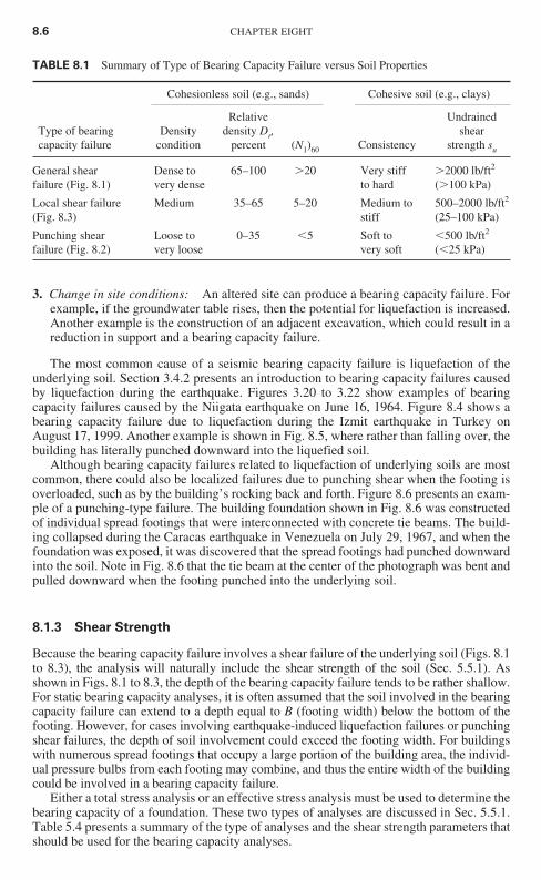
TABLE 8.1 Summary of Type of Bearing Capacity Failure versus Soil Properties
Cohesionless soil (e.g., sands) Cohesive soil (e.g., clays)
Relative Undrained Type of bearing Density density Dr, shear capacity failure condition percent (N1)60 Consistency strength su
General shear Dense to 65–100 �20 Very stiff �2000 lb/ft2
failure (Fig. 8.1) very dense to hard (�100 kPa)
Local shear failure Medium 35–65 5–20 Medium to 500–2000 lb/ft2
(Fig. 8.3) stiff (25–100 kPa)
Punching shear Loose to 0–35 �5 Soft to �500 lb/ft2
failure (Fig. 8.2) very loose very soft (�25 kPa)
Ch08_DAY 10/26/01 2:07 PM Page 8.6
8.1.4 One-Third Increase in Bearing Pressure for Seismic Conditions
When the recommendations are presented for the allowable bearing pressures at a site, it iscommon practice for the geotechnical engineer to recommend that the allowable bearingpressure be increased by a factor of one-third when performing seismic analyses. For exam-ple, in soil reports, it is commonly stated: “For the analysis of earthquake loading, the allow-able bearing pressure and passive resistance may be increased by a factor of one-third.” Therational behind this recommendation is that the allowable bearing pressure has an ample fac-tor of safety, and thus for seismic analyses, a lower factor of safety would be acceptable.
Usually the above recommendation is appropriate for the following materials:
1. Massive crystalline bedrock and sedimentary rock that remains intact during the earth-quake
2. Dense to very dense granular soil
3. Heavily overconsolidated cohesive soil, such as very stiff to hard clays
These materials do not lose shear strength during the seismic shaking, and therefore anincrease in bearing pressure is appropriate.
A one-third increase in allowable bearing pressure should not be recommended for thefollowing materials:
1. Foliated or friable rock that fractures apart during the earthquake
2. Loose soil subjected to liquefaction or a substantial increase in excess pore water pressure
3. Sensitive clays that lose shear strength during the earthquake
4. Soft clays and organic soils that are overloaded and subjected to plastic flow
These materials have a reduction in shear strength during the earthquake. Since thematerials are weakened by the seismic shaking, the static values of allowable bearing pres-
BEARING CAPACITY ANALYSES FOR EARTHQUAKES 8.7
FIGURE 8.4 The building suffered a liquefaction-induced bearing capacity failure during the Izmit earthquakein Turkey on August 17, 1999. (Photograph from the Izmit Collection, EERC, University of California, Berkeley.)
Ch08_DAY 10/26/01 2:07 PM Page 8.7
sure should not be increased for the earthquake analyses. In fact, the allowable bearingpressure may actually have to be reduced to account for the weakening of the soil duringthe earthquake. The remainder of this chapter deals with the determination of the bearingcapacity of soils that are weakened by seismic shaking.
8.2 BEARING CAPACITY ANALYSES FORLIQUEFIED SOIL
8.2.1 Introduction
Section 8.2 deals with the bearing capacity of foundations underlain by liquefied soil. Theliquefaction analysis presented in Chap. 6 can be used to determine those soil layers thatwill liquefy during the design earthquake.
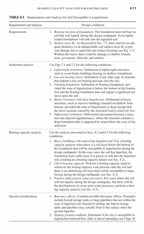
Table 8.3 summarizes the requirements and analyses for soil susceptible to liquefaction.The steps are as follows:
8.8 CHAPTER EIGHT
FIGURE 8.5 The building suffered a liquefaction-inducedpunching shear failure during the Izmit earthquake in Turkey onAugust 17, 1999. (Photograph from the Izmit Collection, EERC,University of California, Berkeley.)
Ch08_DAY 10/26/01 2:07 PM Page 8.8
BEARING CAPACITY ANALYSES FOR EARTHQUAKES 8.9
1. Requirements: The first step is to determine whether the two requirements listed inTable 8.3 are met. If these two requirements are not met, then the foundation is susceptibleto failure during the design earthquake, and special design considerations, such as the useof deep foundations or soil improvement, are required.
2. Settlement analysis: Provided that the two design requirements are met, the nextstep is to perform a settlement analysis using Figs. 7.1 and 7.2. Note that in some cases, thesettlement analysis is unreliable (e.g., heavy buildings with an underlying liquefied soillayer close to the bottom of the foundation).
3. Bearing capacity analysis: There are two different types of bearing capacity analy-sis that can be performed. The first deals with a shear failure where the footing punches intothe liquefied soil layer (Sec. 8.2.2). The second case uses the traditional Terzaghi bearing
FIGURE 8.6 The building foundation shown above was con-structed of individual footings that were interconnected with con-crete tie beams. The building collapsed during the Caracasearthquake in Venezuela on July 29, 1967. When the foundationwas exposed, it was discovered that the spread footings had puncheddownward into the soil. Note that the tie beam at the center of thephotograph was bent and pulled downward when the footingpunched into the underlying soil. (Photograph from the SteinbruggeCollection, EERC, University of California, Berkeley.)
Ch08_DAY 10/26/01 2:07 PM Page 8.9
capacity equation, with a reduction in the bearing capacity factors to account for the loss ofshear strength of the underlying liquefied soil layer (Sec. 8.2.3).
4. Special considerations: Special considerations may be required if the structure issubjected to buoyancy or if there is a sloping ground condition.
8.2.2 Punching Shear Analysis
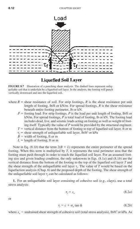
Illustration of Punching Shear. Figure 8.7 illustrates the earthquake-induced punchingshear analysis. The soil layer portrayed by dashed lines represents unliquefiable soil whichis underlain by a liquefied soil layer. For the punching shear analysis, it is assumed that theload will cause the foundation to punch straight downward through the upper unliquefiablesoil layer and into the liquefied soil layer. As shown in Fig. 8.7, this assumption means thatthere will be vertical shear surfaces in the soil that start at the sides of the footing and extendstraight downward to the liquefied soil layer. It is also assumed that the liquefied soil hasno shear strength.
Factor of Safety. Using the assumptions outlined above, the factor of safety (FS) can becalculated as follows:For strip footings:
FS � � (8.1a)
For spread footings:
FS � � (8.1b)2 (B L) (T�f)
P
RP
2T�f
P
RP
8.10 CHAPTER EIGHT
TABLE 8.2 Allowable Bearing Pressures
Allowable bearing Maximum allowable Material type pressure* bearing pressure†
Massive crystalline bedrock 4,000 lb/ft2 (200 kPa) 12,000 lb/ft2 (600 kPa)
Sedimentary and foliated rock 2,000 lb/ft2 (100 kPa) 6,000 lb/ft2 (300 kPa)
Gravel and sandy gravel (GW, GP)‡ 2,000 lb/ft2 (100 kPa) 6,000 lb/ft2 (300 kPa)
Nonplastic soil: sands, silty gravel, 1,500 lb/ft2 (75 kPa) 4,500 lb/ft2 (220 kPa)and nonplastic silt (GM, SW, SP, SM)‡
Plastic soil: silts and clays 1,000 lb/ft2 (50 kPa) 3,000 lb/ft2 (150 kPa)§
(ML, MH, SC, CL, CH)‡
*Minimum footing width and embedment depth equal 1 ft (0.3 m).†An increase of 20 percent of the allowable bearing pressure is allowed for each additional 1 ft (0.3 m) of width
or depth up to the maximum allowable bearing pressures listed in the rightmost column. An exception is plastic soil;see last note.
‡Group symbols from the Unified Soil Classification System.§No increase in the allowable bearing pressure is allowed for an increase in width of the footing.
For dense or stiff soils, allowable bearing values are generally conservative. For very loose or very soft soils,allowable bearing values may be too high.
Source: Data from Uniform Building Code (1997).
Ch08_DAY 10/26/01 2:07 PM Page 8.10
BEARING CAPACITY ANALYSES FOR EARTHQUAKES 8.11
TABLE 8.3 Requirements and Analyses for Soil Susceptible to Liquefaction
Requirements and analyses Design conditions
Requirements 1. Bearing location of foundation: The foundation must not bear onsoil that will liquefy during the design earthquake. Even lightlyloaded foundations will sink into the liquefied soil.
2. Surface layer H1: As discussed in Sec. 7.3, there must be an ade-quate thickness of an unliquefiable soil surface layer H1 to pre-vent damage due to sand boils and surface fissuring (see Fig. 7.3).Without this layer, there could be damage to shallow founda-tions, pavements, flatwork, and utilities.
Settlement analysis Use Figs 7.1 and 7.2 for the following conditions:
1. Lightweight structures: Settlement of lightweight structures,such as wood-frame buildings bearing on shallow foundations.
2. Low net bearing stress: Settlement of any other type of structurethat imparts a low net bearing pressure onto the soil.
3. Floating foundation: Settlement of floating foundations, pro-vided the zone of liquefaction is below the bottom of the founda-tion and the floating foundation does not impart a significant netstress upon the soil.
4. Heavy structures with deep liquefaction: Settlement of heavystructures, such as massive buildings founded on shallow foun-dations, provided the zone of liquefaction is deep enough thatthe stress increase caused by the structural load is relatively low.
5. Differential settlement: Differential movement between a struc-ture and adjacent appurtenances, where the structure contains adeep foundation that is supported by strata below the zone of liq-uefaction.
Bearing capacity analysis Use the analyses presented in Secs. 8.2 and 8.3 for the following conditions:
1. Heavy buildings with underlying liquefied soil: Use a bearingcapacity analysis when there is a soil layer below the bottom ofthe foundation that will be susceptible to liquefaction during thedesign earthquake. In this case, once the soil has liquefied, thefoundation load could cause it to punch or sink into the liquefiedsoil, resulting in a bearing capacity failure (see Sec. 8.2).
2. Check bearing capacity: Perform a bearing capacity analysiswhenever the footing imposes a net pressure onto the soil andthere is an underlying soil layer that will be susceptible to lique-faction during the design earthquake (see Sec. 8.2).
3. Positive induced pore water pressures: For cases where the soilwill not liquefy during the design earthquake, but there will bethe development of excess pore water pressures, perform a bear-ing capacity analysis (see Sec. 8.3).
Special considerations 1. Buoyancy effects: Consider possible buoyancy effects. Examplesinclude buried storage tanks or large pipelines that are within thezone of liquefied soil. Instead of settling, the buried storagetanks and pipelines may actually float to the surface when theground liquefies.
2. Sloping ground condition: Determine if the site is susceptible toliquefaction-induced flow slide or lateral spreading (see Chap. 9).
Ch08_DAY 10/26/01 2:07 PM Page 8.11
where R � shear resistance of soil. For strip footings, R is the shear resistance per unitlength of footing, lb/ft or kN/m. For spread footings, R is the shear resistancebeneath entire footing perimeter, lb or kN.
P � footing load. For strip footings, P is the load per unit length of footing, lb/ft orkN/m. For spread footings, P is total load of footing, lb or kN. The footing loadincludes dead, live, and seismic loads acting on footing as well as weight of foot-ing itself. Typically the value of P would be provided by the structural engineer.
T � vertical distance from the bottom of footing to top of liquefied soil layer, ft or m�f � shear strength of unliquefiable soil layer, lb/ft2 or kPaB � width of footing, ft or mL � length of footing, ft or m
Note in Eq. (8.1b) that the term 2(B L) represents the entire perimeter of the spreadfooting. When this term is multiplied by T, it represents the total perimeter area that thefooting must push through in order to reach the liquefied soil layer. For an assumed foot-ing size and given loading condition, the only unknowns in Eqs. (8.1a) and (8.1b) are thevertical distance from the bottom of the footing to the top of the liquefied soil layer T andthe shear strength of the unliquefiable soil layer �f. The value of T would be based on theliquefaction analysis (Chap. 6) and the proposed depth of the footing. The shear strength ofthe unliquefiable soil layer �f can be calculated as follows:
1. For an unliquefiable soil layer consisting of cohesive soil (e.g., clays), use a totalstress analysis:
�f � su (8.2a)
or
�f � c �h tan � (8.2b)
where su � undrained shear strength of cohesive soil (total stress analysis), lb/ft2 or kPa. As
8.12 CHAPTER EIGHT
FIGURE 8.7 Illustration of a punching shear analysis. The dashed lines represent unliq-uefiable soil that is underlain by a liquefied soil layer. In the analysis, the footing will punchvertically downward and into the liquefied soil.
Ch08_DAY 10/26/01 2:07 PM Page 8.12
discussed in Sec. 5.5.1, often undrained shear strength is obtained from uncon-fined compression tests or vane shear tests.
c, � � undrained shear strength parameters (total stress analysis). As discussed in Sec.5.5.1, these undrained shear strength parameters are often obtained from triax-ial tests, such as unconsolidated undrained triaxial compression test (ASTM D2850-95, 2000) or consolidated undrained triaxial compression tests (ASTM D4767-95, 2000).
�h � horizontal total stress, lb/ft2 or kPa. Since vertical shear surfaces are assumed(see Fig. 8.7), normal stress acting on shear surfaces will be the horizontal totalstress. For cohesive soil, �h is often assumed to be equal to 1⁄2 �v.
2. For an unliquefiable soil layer consisting of cohesionless soil (e.g., sands), use aneffective stress analysis:
�f � �h′ tan �′ � k0�v0′ tan �′ (8.2c)
where �h′ � horizontal effective stress, lb/ft2 or kPa. Since vertical shear surfaces areassumed (see Fig. 8.7), the normal stress acting on the shear surface will be thehorizontal effective stress. The horizontal effective stress �h′ is equal to thecoefficient of earth pressure at rest k0 times the vertical effective stress �v0′ , or�h′ � k0 �v0′ .
�′ � effective friction angle of cohesionless soil (effective stress analysis).Effective friction angle could be determined from drained direct shear tests orfrom empirical correlations such as shown in Figs. 5.12 and 5.14.
Example Problems. The following example problems illustrate the use of Eqs. (8.1) and (8.2).Example Problem for Cohesive Surface Layer (Total Stress Analysis). Use the data
from Prob. 6.15, which deals with the subsurface conditions shown in Fig. 6.15 (i.e., thesewage disposal site). Based on the standard penetration test data, the zone of liquefactionextends from a depth of 1.2 to 6.7 m below ground surface. Assume the surface soil (upper1.2 m) shown in Fig. 6.15 consists of an unliquefiable cohesive soil and during construc-tion, an additional 1.8-m-thick layer of cohesive soil will be placed at ground surface. Usea peak ground acceleration amax of 0.20g.
Assume that after the 1.8-m-thick layer is placed at ground surface, it is proposed toconstruct a sewage disposal plant. The structural engineer would like to use shallow stripfootings to support exterior walls and interior spread footings to support isolated columns.It is proposed that the bottom of the footings be at a depth of 0.5 m below ground surface.The structural engineer has also indicated that the maximum total loads (including theweight of the footing and the dynamic loads) are 50 kN/m for the strip footings and 500 kNfor the spread footings. It is desirable to use 1-m-wide strip footings and square spread foot-ings that are 2 m wide.
For both the existing 1.2-m-thick unliquefiable cohesive soil layer and the proposedadditional 1.8-m-thick fill layer, assume that the undrained shear strength su of the soil isequal to 50 kPa. Calculate the factor of safety of the footings, using Eq. (8.1).
Solution. The first step is to check the two requirements in Table 8.3. Since the foot-ings will be located within the upper unliquefiable cohesive soil, the first requirement ismet. As indicated in the example problem in Sec. 7.3.3, the surface unliquefiable soil layermust be at least 3 m thick to prevent liquefaction-induced ground damage. Since a fill layerequal to 1.8 m is proposed for the site, the final thickness of the unliquefiable soil will beequal to 3 m. Thus the second requirement is met.
To calculate the factor of safety in terms of a bearing capacity failure for the strip andspread footings, the following values are used:
BEARING CAPACITY ANALYSES FOR EARTHQUAKES 8.13
Ch08_DAY 10/26/01 2:07 PM Page 8.13
P � 50 kN/m for strip footing and 500 kN for spread footing
T � 2.5 m i.e., total thickness of unliquefiable soil layer minus footing embedmentdepth � 3 m � 0.5 m � 2.5 m
�f � su � 50 kPa � 50 kN/m2
B � L � 2 m
Substituting the above values into Eqs. (8.1a) and (8.1b) yields
FS � � � 5.0 strip footing
FS � � � 2.0 spread footing
For a seismic analysis, a factor of safety of 5.0 would be acceptable, but the factor ofsafety of 2.0 would probably be too low.
Example Problem for Cohesionless Surface Layer (Effective Stress Analysis). Use thesame data, but assume the surface soil and the proposed 1.8-m-thick fill layer are sands withan effective friction angle �′ equal to 32° and a coefficient of earth pressure at rest k0 equal to0.5. Also assume that instead of the groundwater table being at a depth of 0.4 m (see Fig. 6.15),it is at a depth of 1.2 m below the existing ground surface. Calculate the factor of safety of thefootings, using Eq. (8.1).
Solution. To calculate the factor of safety in terms of a bearing capacity failure for thestrip and spread footings, the following values are used:
P � 50 kN/m for strip footing and 500 kN for spread footing
T � 2.5 m i.e., total thickness of unliquefiable soil layer minus footing embedmentdepth � 3 m � 0.5 m � 2.5 m
�v0′ � �v � u Since soil is above groundwater table, assume u � 0. Use a total unitweight of 18.3 kN/m3 (Prob. 6.15) and an average depth of 1.75 m [(0.5 3.0)/2 � 1.75 m] or �v0′ � 18.3 � 1.75 � 32 kPa.
�f � k0 �v0′ tan �′ � (0.5) (32 kPa) (tan 32°) � 10 kPa � 10 kN/m2 [Eq. (8.2c)]
B � L � 2 m
Substituting the above values into Eqs. (8.1a) and (8.1b) gives
FS � � � 1.0 strip footing
FS � � � 0.4 spread footing
For the seismic bearing capacity analyses, these factors of safety would indicate thatboth the strip and spread footings would punch down through the upper sand layer and intothe liquefied soil layer.
As a final check, the FS calculated from the earthquake-induced punching shear analy-sis must be compared with the FS calculated from the static bearing capacity analysis (i.e.,nonearthquake condition). The reason for this comparison is that FS for the earthquake
2 (2 2) (2.5 m) (10 kN/m2)
500 kN
2 (B L) T�f
P
2 (2.5 m) (10 kN/m2)
50 kN/m
2T�f
P
2 (2 2) (2.5 m) (50 kN/m2)
500 kN
2 (B L) T�f
P
2 (2.5 m) (50 kN/m2)
50 kN/m
2 T�f
P
8.14 CHAPTER EIGHT
Ch08_DAY 10/26/01 2:07 PM Page 8.14

punching shear case [Eq. (8.1)] could exceed the FS calculated from the static condition.This often occurs when the liquefied soil layer is at a significant depth below the bottom ofthe footing, or in other words at high values of T/B. In any event, the lower value of FS fromeither the earthquake punching shear analysis or the static bearing capacity analysis wouldbe considered the critical condition.
8.2.3 Terzaghi Bearing Capacity Equation
Introduction. The most commonly used bearing capacity equation is that equation devel-oped by Terzaghi (1943). For a uniform vertical loading of a strip footing, Terzaghi (1943)assumed a shallow footing and general shear failure (Fig. 8.1) in order to develop the fol-lowing bearing capacity equation:
qult � � cNc 1⁄2�tBN� �tDf Nq (8.3)
where qult � ultimate bearing capacity for a strip footing, kPa or lb/ft2
Qult � vertical load causing a general shear failure of underlying soil (Fig. 8.1)B � width of strip footing, m or ftL � length of strip footing, m or ft�t � total unit weight of soil, kN/m3 or lb/ft3
Df � vertical distance from ground surface to bottom of strip footing, m or ftc � cohesion of soil underlying strip footing, kPa or lb/ft2
Nc, N�, and Nq � dimensionless bearing capacity factors
As indicated in Eq. (8.3), three terms are added to obtain the ultimate bearing capacityof the strip footing. These terms represent the following:
cNc The first term accounts for the cohesive shear strength of the soil located belowthe strip footing. If the soil below the footing is cohesionless (that is, c � 0), then thisterm is zero.1⁄2�tBN� The second term accounts for the frictional shear strength of the soillocated below the strip footing. The friction angle � is not included in this term, but isaccounted for by the bearing capacity factor N�. Note that �t represents the total unitweight of the soil located below the footing.
�tDf Nq This third term accounts for the soil located above the bottom of the footing.The value of �t times Df represents a surcharge pressure that helps to increase the bear-ing capacity of the footing. If the footing were constructed at ground surface (that is, Df � 0), then this term would equal zero. This third term indicates that the deeper thefooting, the greater the ultimate bearing capacity of the footing. In this term, �t repre-sents the total unit weight of the soil located above the bottom of the footing. The totalunit weights above and below the footing bottom may be different, in which case dif-ferent values are used in the second and third terms of Eq. (8.3).
As previously mentioned, Eq. (8.3) was developed by Terzaghi (1943) for strip foot-ings. For other types of footings and loading conditions, corrections need to be applied tothe bearing capacity equation. Many different types of corrections have been proposed(e.g., Meyerhof 1951, 1953, 1965). One commonly used form of the bearing capacity equa-tion for spread (square footings) and combined footings (rectangular footings) subjected touniform vertical loading is as follows (NAVFAC DM-7.2, 1982):
QultBL
BEARING CAPACITY ANALYSES FOR EARTHQUAKES 8.15
Ch08_DAY 10/26/01 2:07 PM Page 8.15
qult � � cNc �1 0.3 � 0.4�tBN� �tDf Nq (8.4)
Equation (8.4) is similar to Eq. (8.3), and the terms have the same definitions. An impor-tant consideration is that for the strip footing, the shear strength is actually based on a planestrain condition (soil is confined along the long axis of the footing). It has been stated thatthe friction angle � is about 10 percent higher in the plane strain condition than the frictionangle � measured in the triaxial apparatus (Meyerhof 1961, Perloff and Baron 1976). Laddet al. (1977) indicated that the friction angle � in plane strain is larger than � in triaxialshear by 4° to 9° for dense sands. A difference in friction angle of 4° to 9° has a significantimpact on the bearing capacity factors. In practice, plane strain shear strength tests are notperformed, and thus there is an added factor of safety for the strip footing compared to theanalysis for spread or combined footings.
Bearing Capacity Equation for a Cohesive Soil Layer Underlain by Liquefied Soil. Forthe situation of a cohesive soil layer overlying a sand that will be susceptible to liquefac-tion, a total stress analysis can be performed. This type of analysis uses the undrained shearstrength of the cohesive soil (Sec. 5.5.1). The undrained shear strength su could be deter-mined from field tests, such as the vane shear test (VST), or in the laboratory from uncon-fined compression tests. Using a total stress analysis, su � c and � � 0 for Eqs. (8.3) and(8.4). For � � 0, the Terzaghi bearing capacity factors are N� � 0 and Nq � 1 (Terzaghi1943). The bearing capacity equations, (8.3) and (8.4), thus reduce to the following:For strip footings:
qult � cNc �tDf � suNc �tDf (8.5a)
For spread footings:
qult � cNc �1 0.3 � �tDf � suNc �1 0.3 � �tDf (8.5b)
In dealing with shallow footings, the second term (�tDf ) in Eq. 8.5 tends to be rathersmall. Thus by neglecting the second term in Eq. (8.5), the final result is as follows:For strip footings:
qult � cNc � suNc (8.6a)
For spread footings:
qult � cNc �1 0.3 � � suNc �1 0.3 � (8.6b)
In order to use Eq. (8.6) to evaluate the ability of a footing to shear through a cohesivesoil layer and into a liquefied soil layer, the undrained shear strength of the cohesive soilmust be known (that is, c � su). In addition, the bearing capacity factor Nc must be deter-mined. The presence of an underlying liquefied soil layer will tend to decrease the valuesfor Nc. Figure 8.8 can be used to determine the values of Nc for the condition of a unlique-fiable cohesive soil layer overlying a soil layer that is expected to liquefy during the designearthquake. In Fig. 8.8, the terms are defined as follows:
Layer 1 � upper cohesive soil layer that has a uniform undrained shear strength, lb/ft2 or kPa, or su � c � c1
BL
BL
BL
BL
BL
QultBL
8.16 CHAPTER EIGHT
Ch08_DAY 10/26/01 2:07 PM Page 8.16
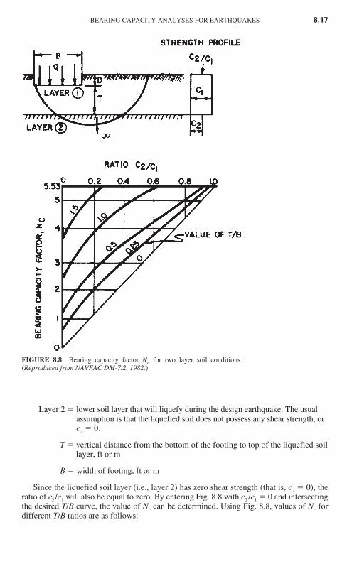
Layer 2 � lower soil layer that will liquefy during the design earthquake. The usual assumption is that the liquefied soil does not possess any shear strength, or c2 � 0.
T � vertical distance from the bottom of the footing to top of the liquefied soil layer, ft or m
B � width of footing, ft or m
Since the liquefied soil layer (i.e., layer 2) has zero shear strength (that is, c2 � 0), theratio of c2 /c1 will also be equal to zero. By entering Fig. 8.8 with c2 /c1 � 0 and intersectingthe desired T/B curve, the value of Nc can be determined. Using Fig. 8.8, values of Nc fordifferent T/B ratios are as follows:
BEARING CAPACITY ANALYSES FOR EARTHQUAKES 8.17
FIGURE 8.8 Bearing capacity factor Nc for two layer soil conditions.(Reproduced from NAVFAC DM-7.2, 1982.)
Ch08_DAY 10/26/01 2:07 PM Page 8.17
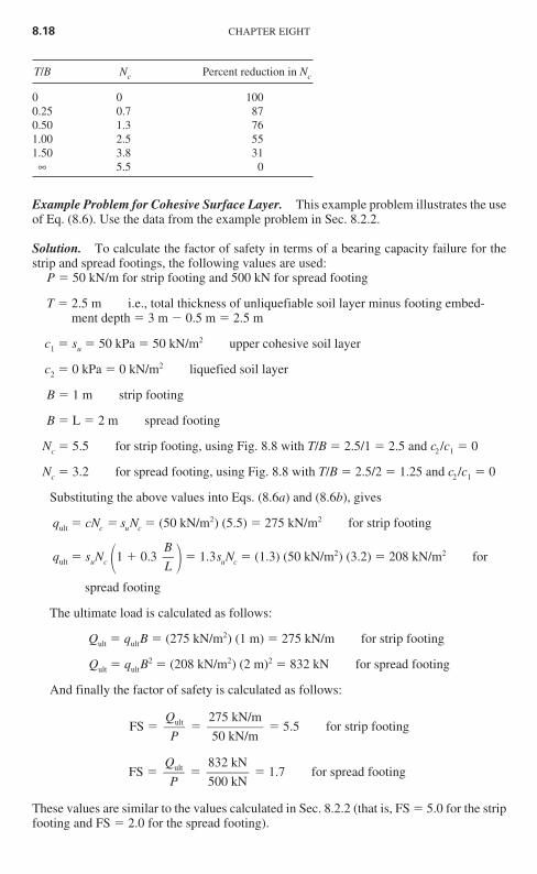
T/B Nc Percent reduction in Nc
0 0 1000.25 0.7 870.50 1.3 761.00 2.5 551.50 3.8 31∞ 5.5 0
Example Problem for Cohesive Surface Layer. This example problem illustrates the useof Eq. (8.6). Use the data from the example problem in Sec. 8.2.2.
Solution. To calculate the factor of safety in terms of a bearing capacity failure for thestrip and spread footings, the following values are used:
P � 50 kN/m for strip footing and 500 kN for spread footing
T � 2.5 m i.e., total thickness of unliquefiable soil layer minus footing embed-ment depth � 3 m � 0.5 m � 2.5 m
c1 � su � 50 kPa � 50 kN/m2 upper cohesive soil layer
c2 � 0 kPa � 0 kN/m2 liquefied soil layer
B � 1 m strip footing
B � L � 2 m spread footing
Nc � 5.5 for strip footing, using Fig. 8.8 with T/B � 2.5/1 � 2.5 and c2 /c1 � 0
Nc � 3.2 for spread footing, using Fig. 8.8 with T/B � 2.5/2 � 1.25 and c2 /c1 � 0
Substituting the above values into Eqs. (8.6a) and (8.6b), gives
qult � cNc � suNc � (50 kN/m2) (5.5) � 275 kN/m2 for strip footing
qult � suNc �1 0.3 � � 1.3suNc � (1.3) (50 kN/m2) (3.2) � 208 kN/m2 for
spread footing
The ultimate load is calculated as follows:
Qult � qultB � (275 kN/m2) (1 m) � 275 kN/m for strip footing
Qult � qultB2 � (208 kN/m2) (2 m)2 � 832 kN for spread footing
And finally the factor of safety is calculated as follows:
FS � � � 5.5 for strip footing
FS � � � 1.7 for spread footing
These values are similar to the values calculated in Sec. 8.2.2 (that is, FS � 5.0 for the stripfooting and FS � 2.0 for the spread footing).
832 kN500 kN
Qult
P
275 kN/m50 kN/m
Qult
P
BL
8.18 CHAPTER EIGHT
Ch08_DAY 10/26/01 2:07 PM Page 8.18
8.2.4 Deep Foundations
Deep foundations are used when the upper soil stratum is too soft, weak, or compressibleto support the static and earthquake-induced foundation loads. Deep foundations are alsoused when there is a possibility of undermining of the foundation. For example, bridgepiers are often founded on deep foundations to prevent a loss of support due to flood con-ditions which could cause river bottom scour. In addition, deep foundations are used whenthe expected settlement is excessive (Chap. 7), to prevent ground surface damage of thestructure (Sec. 7.3), or to prevent a bearing capacity failure caused by the liquefaction of anunderlying soil deposit.
Types of Deep Foundations. The most common types of deep foundations are piles andpiers that support individual footings or mat foundations. Piles are defined as relativelylong, slender, columnlike members often made of steel, concrete, or wood that are eitherdriven into place or cast in place in predrilled holes. Common types of piles are as follows:
� Batter pile: This pile is driven in at an angle inclined to the vertical to provide highresistance to lateral loads. If the soil should liquefy during an earthquake, then the lateralresistance of the batter pile may be significantly reduced.
� End-bearing pile: The support capacity of this pile is derived principally from the resis-tance of the foundation material on which the pile tip rests. End-bearing piles are oftenused when a soft upper layer is underlain by a dense or hard stratum. If the upper softlayer should settle or liquefy during an earthquake, the pile could be subjected to down-drag forces, and the pile must be designed to resist these soil-induced forces.
� Friction pile: The support capacity of this pile is derived principally from the resistanceof the soil friction and/or adhesion mobilized along the side of the pile. Friction piles areoften used in soft clays where the end-bearing resistance is small because of punchingshear at the pile tip. If the soil is susceptible to liquefaction during an earthquake, thenboth the frictional resistance and the lateral resistance of the pile may be lost during theearthquake.
� Combined end-bearing and friction pile: This pile derives its support capacity fromcombined end-bearing resistance developed at the pile tip and frictional and/or adhesionresistance on the pile perimeter.
A pier is defined as a deep foundation system, similar to a cast-in-place pile, that con-sists of a columnlike reinforced concrete member. Piers are often of large enough diameterto enable down-hole inspection. Piers are also commonly referred to as drilled shafts, boredpiles, or drilled caissons.
There are many other methods available for forming deep foundation elements.Examples include earth stabilization columns, such as (NAVFAC DM-7.2, 1982):
� Mixed-in-place piles: A mixed-in-place soil-cement or soil-lime pile.� Vibroflotation-replacement stone columns: Vibroflotation or another method is used to
make a cylindrical, vertical hole which is filled with compacted open-graded gravel orcrushed rock. The stone columns also have the additional capability of reducing thepotential for soil liquefaction by allowing the earthquake-induced pore water pressuresto rapidly dissipate as water flows into the highly permeable open-graded gravel orcrushed rock.
� Grouted stone columns: These are similar to the above but include filling voids withbentonite-cement or water-sand-bentonite cement mixtures.
� Concrete Vibroflotation columns: These are similar to stone columns, but concrete isused instead of gravel.
BEARING CAPACITY ANALYSES FOR EARTHQUAKES 8.19
Ch08_DAY 10/26/01 2:07 PM Page 8.19
Design Criteria. Several different items are used in the design and construction of piles:
1. Engineering analysis: Based on the results of engineering analysis, a deep foun-dation could be designed and constructed such that it penetrates all the soil layers that areexpected to liquefy during the design earthquake. In this case, the deep foundation willderive support from the unliquefiable soil located below the potentially troublesome soilstrata. However, the presence of down-drag loads as well as the loss of lateral resistancedue to soil liquefaction must be considered in the engineering analysis.
If a liquefiable soil layer is located below the bottom of the deep foundation, then Sec.8.2.2 could be used to analyze the possibility of the deep foundation’s punching into theunderlying liquefied soil layer. For end-bearing piles, the load applied to the pile cap canbe assumed to be transferred to the pile tips. Then based on the shear strength of the unliq-uefiable soil below the bottom of the piles as well as the vertical distance from the pile tipto the liquefiable soil layer, the factor of safety can be calculated using Eq. (8.1b). Note thatB and L in Eq. (8.1b) represent the width and length, respectively, of the pile group.
2. Field load tests: Prior to the construction of the foundation, a pile or pier could beload-tested in the field to determine its carrying capacity. Because of the uncertainties inthe design of piles based on engineering analyses, pile load tests are common. The pile loadtest can often result in a more economical foundation then one based solely on engineeringanalyses. Pile load tests can even be performed to evaluate dynamic loading conditions. Forexample, ASTM provides guidelines on the dynamic testing of piles (for example, D 4945-96, “Standard Test Method for High-Strain Dynamic Testing of Piles” 2000). In this testmethod, ASTM states:
This test method is used to provide data on strain or force and acceleration, velocity or dis-placement of a pile under impact force. The data are used to estimate the bearing capacity andthe integrity of the pile, as well as hammer performance, pile stresses, and soil dynamics char-acteristics, such as soil damping coefficients and quake values.
A limitation of field load tests is that they cannot simulate the response of the pile forthose situations where the soil is expected to liquefy during the design earthquake. Thus theresults of the pile load tests would have to be modified for the expected liquefaction con-ditions.
3. Application of pile driving resistance: In the past, the pile capacity was estimatedbased on the driving resistance during the installation of the pile. Pile driving equations,such as the Engineering News formula (Wellington 1888), were developed that related thepile capacity to the energy of the pile driving hammer and the average net penetration ofthe pile per blow of the pile hammer. But studies have shown that there is no satisfactoryrelationship between the pile capacity from pile driving equations and the pile capacitymeasured from load tests. Based on these studies, it has been concluded that use of pile dri-ving equations is no longer justified (Terzaghi and Peck 1967).
Especially for high displacement piles that are closely spaced, the vibrations and soildisplacement associated with driving the piles will densify granular soil. Thus the lique-faction resistance of the soil is often increased due the pile driving (see compaction piles inSec. 12.3.3).
4. Specifications and experience: Other factors that should be considered in the deepfoundation design include the governing building code or agency requirements and localexperience. Local experience, such as the performance of deep foundations during priorearthquakes, can be a very important factor in the design and construction of pile foundations.
The use of pile foundations is discussed further in Chap. 13.
8.20 CHAPTER EIGHT
Ch08_DAY 10/26/01 2:07 PM Page 8.20
8.2.5 Other Design Considerations
There are many other possible considerations in the determination of the bearing capacityof soil that will liquefy during the design earthquake. Some important items are as follows:
Determination of T. An essential part of the bearing capacity analysis is the determina-tion of T, which is the distance from the bottom of the footing to the top of the liquefied soillayer. This distance may be easy to determine if the upper unliquefiable soil layer is a cohe-sive soil, such as a fat clay.
It is much more difficult to determine T for soil that is below the groundwater table andhas a factor of safety against liquefaction that is slightly greater than 1.0. This is because if a lower layer liquefies, an upward flow of water could induce liquefaction of the layerthat has a factor of safety slightly greater than 1.0. In addition, the shear stress induced onthe soil by the foundation can actually reduce the liquefaction resistance of loose soil (seeSec. 9.4.2). Because of these effects, considerable experience and judgment are required inthe determination of T.
Lateral Loads. In addition to the vertical load acting on the footing, it may also be sub-jected to both static and dynamic lateral loads. A common procedure is to treat lateral loadsseparately and resist the lateral loads by using the soil pressure acting on the sides of thefooting (passive pressure) and by using the frictional resistance along the bottom of thefooting.
Moments and Eccentric Loads. It is always desirable to design and construct shallow foot-ings so that the vertical load is applied at the center of gravity of the footing. For combinedfootings that carry more than one vertical load, the combined footing should be designed andconstructed so that the vertical loads are symmetric. For earthquake loading, the footing isoften subjected to a moment. This moment can be represented by a load P that is offset a cer-tain distance (known as the eccentricity) from the center of gravity of the footing.
There are many different methods to evaluate eccentrically loaded footings. Because aneccentrically loaded footing will create a higher bearing pressure under one side than underthe opposite side, one approach is to evaluate the actual pressure distribution beneath thefooting. The usual procedure is to assume a rigid footing (hence linear pressure distribu-tion) and use the section modulus (1⁄6 B2) in order to calculate the largest and smallest bear-ing pressures. For a footing having a width B, the largest q′ and smallest q″ bearingpressures are as follows:
q′ � (8.7a)
q″ � (8.7b)
where q′ � largest bearing pressure underneath footing, which is located along thesame side of footing as the eccentricity, kPa or lb/ft2
q″ � smallest bearing pressure underneath footing, which is located at the oppo-site side of footing, kPa or lb/ft2
Q � P � footing load, lb/ft or kN/m. For both strip footings and spread footings, Q is the load per unit length of footing. Footing load includes dead, live, andseismic loads acting on the footing as well as the weight of the footing itself.Typically the value of Q would be provided by the structural engineer.
Q (B � 6e)
B2
Q (B 6e)
B2
BEARING CAPACITY ANALYSES FOR EARTHQUAKES 8.21
Ch08_DAY 10/26/01 2:07 PM Page 8.21
e � eccentricity of the load Q, that is, the lateral distance from Q to the centerof gravity of footing, m or ft
B � width of footing, m or ft
A usual requirement is that the load Q be located within the middle one-third of the foot-ing, and the above equations are valid only for this condition. The value of q′ must notexceed the allowable bearing pressure qall.
Figure 8.9 presents another approach for footings subjected to moments. As indicatedin Fig. 8.9a, the moment M is converted to a load Q that is offset from the center of grav-ity of the footing by an eccentricity e. This approach is identical to the procedure outlinedfor Eq. (8.7).
The next step is to calculate a reduced area of the footing. As indicated in Fig. 8.9b, thenew footing dimensions are calculated as L′ � L � 2e1 and B′ � B � 2e2. A reduction infooting dimensions in both directions would be applicable only for the case where the foot-ing is subjected to two moments, one moment in the long direction of the footing (hence e1)and the other moment across the footing (hence e2). If the footing is subjected to only onemoment in either the long or short direction of the footing, then the footing is reduced inonly one direction. Similar to Eq. (8.7), this method should be utilized only if the load Q islocated within the middle one-third of the footing.
Once the new dimensions L′ and B′ of the footing have been calculated, the procedureoutlined in Sec. 8.2.3 is used by substituting L′ for L and B′ for B.
Sloping Ground Conditions. Although methods have been developed to determine theallowable bearing capacity of foundations at the top of slopes (e.g., NAVFAC DM-7.2,1982, page 7.2-135), these methods should be used with caution when dealing with earth-quake analyses of soil that will liquefy during the design earthquake. This is because, asshown in Sec. 3.4, the site could be impacted by liquefaction-induced lateral spreading andflow slides. Even if the general vicinity of the site is relatively level, the effect of liquefac-tion on adjacent slopes or retaining walls must be included in the analysis. For example,Fig. 8.10 shows an example of a warehouse that experienced 2 m of settlement due to lat-eral movement of a quay wall caused by the liquefaction of a sand layer. If the site consistsof sloping ground or if there is a retaining wall adjacent to the site, then in addition to abearing capacity analysis, a slope stability analysis (Chap. 9) or a retaining wall analysis(Chap. 10) should also be performed.
Inclined Base of Footing. Charts have been developed to determine the bearing capac-ity factors for footings having inclined bottoms. However, it has been stated that inclinedbases should never be constructed for footings (AASHTO 1996). During the earthquake,the inclined footing could translate laterally along the sloping soil or rock contact. If a slop-ing contact of underlying hard material will be encountered during the excavation of thefooting, then the hard material should be excavated in order to construct a level footing thatis entirely founded within the hard material.
8.2.6 Example Problem
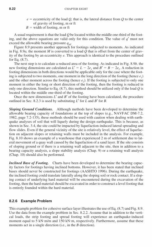
This example problem for cohesive surface layer illustrates the use of Eq. (8.7) and Fig. 8.9.Use the data from the example problem in Sec. 8.2.2. Assume that in addition to the verti-cal loads, the strip footing and spread footing will experience an earthquake-inducedmoment equal to 5 kN m/m and 150 kN m, respectively. Furthermore, assume that thesemoments act in a single direction (i.e., in the B direction).
8.22 CHAPTER EIGHT
Ch08_DAY 10/26/01 2:07 PM Page 8.22
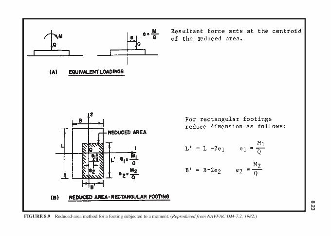
FIGURE 8.9 Reduced-area method for a footing subjected to a moment. (Reproduced from NAVFAC DM-7.2, 1982.)
8.2
3
Ch08_DAY 10/26/01 2:07 PM Page 8.23

Solution for Strip Footing Using Eq. (8.7). To calculate the factor of safety in terms ofa bearing capacity failure for the strip footing, the following values are used:
Q � P � 50 kN/m for strip footing
e � � � 0.10 m for middle one-third of footing, e cannot exceed
0.17 m, and therefore e is within middle one-third of footing
q′ � � � 80 kN/m2 [Eq. (8.7)]
T � 2.5 m i.e., total thickness of unliquefiable soil layer minus footing embedment depth � 3 m � 0.5 m � 2.5 m
c1 � su � 50 kPa � 50 kN/m2 upper cohesive soil layer
c2 � 0 kPa � 0 kN/m2 liquefied soil layer
B � 1 m
Nc � 5.5 using Fig. 8.8 with T/B � 2.5/1.0 � 2.5 and c2/c1 � 0
Using the Terzaghi bearing capacity equation to calculate qult yields
50 [1 (6) (0.1)]
12
Q (B 6e)
B2
5 kN m/m
50 kN/m
MQ
8.24 CHAPTER EIGHT
FIGURE 8.10 Damage to a warehouse due to lateral movement of a quay wall in Zelenica. The liquefac-tion of the sand layer was caused by the Monte Negro earthquake on April 15, 1979. (Reproduced fromIshihara 1985.)
Ch08_DAY 10/26/01 2:07 PM Page 8.24
qult � cNc � suNc � (50 kN/m2) (5.5) � 275 kN/m2 [Eq. (8.6a) ]
And finally the factor of safety is calculated as follows:
FS � � � 3.4
Solution for Strip Footing Using Fig. 8.9. To calculate the factor of safety in terms of abearing capacity failure for the strip footing, the following values are used:
Q � P � 50 kN/m for strip footing
e � � � 0.10 m for middle one-third of footing, e cannot
exceed 0.17 m, and therefore e is within middle one-third of footing
B′ � B � 2e � 1 � 2 (0.10) � 0.8 m Fig. 8.9
T � 2.5 m i.e., total thickness of unliquefiable soil layer minus footing embedment depth � 3 m � 0.5 m � 2.5 m
c1 � su � 50 kPa � 50 kN/m2 upper cohesive soil layer
c2 � 0 kPa � 0 kN/m2 liquefied soil layer
Nc � 5.5 using Fig. 8.8 with T/B � 2.5/1.0 � 2.5 and c2/c1 � 0
Using the Terzaghi bearing capacity equation to calculate qult gives
qult � cNc � suNc � (50 kN/m2) (5.5) � 275 kN/m2 [Eq. (8.6a) ]
Qult � qultB′ � (275 kN/m2) (0.8 m) � 220 kN/m
And finally the factor of safety is calculated as follows:
FS � � � 4.4
Solution for Spread Footing Using Eq. (8.7). To calculate the factor of safety in termsof a bearing capacity failure for the spread footing, the following values are used:
Q � P � 500 kN for spread footing
e � � � 0.30 m for middle one-third of footing, e cannot
exceed 0.33 m, and therefore e is within middle one-third of footing
Converting Q to a load per unit length of the footing yields
Q � � 250 kN/m500 kN
2 m
150 kN m
500 kN
MQ
220 kN/m50 kN/m
QultQ
5 kN m/m
50 kN/m
MQ
275 kN/m2
80 kN/m2
qultq′
BEARING CAPACITY ANALYSES FOR EARTHQUAKES 8.25
Ch08_DAY 10/26/01 2:07 PM Page 8.25
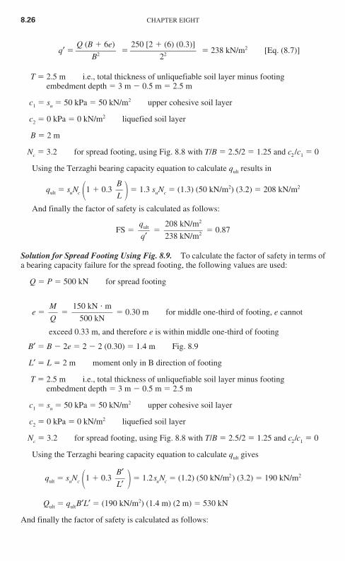
q′ � � � 238 kN/m2 [Eq. (8.7)]
T � 2.5 m i.e., total thickness of unliquefiable soil layer minus footing embedment depth � 3 m � 0.5 m � 2.5 m
c1 � su � 50 kPa � 50 kN/m2 upper cohesive soil layer
c2 � 0 kPa � 0 kN/m2 liquefied soil layer
B � 2 m
Nc � 3.2 for spread footing, using Fig. 8.8 with T/B � 2.5/2 � 1.25 and c2 /c1 � 0
Using the Terzaghi bearing capacity equation to calculate qult results in
qult � suNc �1 0.3 � � 1.3 suNc � (1.3) (50 kN/m2) (3.2) � 208 kN/m2
And finally the factor of safety is calculated as follows:
FS � � � 0.87
Solution for Spread Footing Using Fig. 8.9. To calculate the factor of safety in terms ofa bearing capacity failure for the spread footing, the following values are used:
Q � P � 500 kN for spread footing
e � � � 0.30 m for middle one-third of footing, e cannot
exceed 0.33 m, and therefore e is within middle one-third of footing
B′ � B � 2e � 2 � 2 (0.30) � 1.4 m Fig. 8.9
L′ � L � 2 m moment only in B direction of footing
T � 2.5 m i.e., total thickness of unliquefiable soil layer minus footing embedment depth � 3 m � 0.5 m � 2.5 m
c1 � su � 50 kPa � 50 kN/m2 upper cohesive soil layer
c2 � 0 kPa � 0 kN/m2 liquefied soil layer
Nc � 3.2 for spread footing, using Fig. 8.8 with T/B � 2.5/2 � 1.25 and c2/c1 � 0
Using the Terzaghi bearing capacity equation to calculate qult gives
qult � suNc �1 0.3 � � 1.2suNc � (1.2) (50 kN/m2) (3.2) � 190 kN/m2
Qult � qultB′L′ � (190 kN/m2) (1.4 m) (2 m) � 530 kN
And finally the factor of safety is calculated as follows:
B′L′
150 kN m
500 kN
MQ
208 kN/m2
238 kN/m2
qultq′
BL
250 [2 (6) (0.3)]
22
Q (B 6e)
B2
8.26 CHAPTER EIGHT
Ch08_DAY 10/26/01 2:07 PM Page 8.26
FS � � � 1.06
In summary, the factors of the safety factor in terms of a bearing capacity failure for thestrip and spread footings are as follows:
Factor of safety
Method Strip footing Spread footing
Using Eq. (8.7a) 3.4 0.87Using Fig. 8.9 4.4 1.06No moment (i.e., values from 5.5 1.7Sec. 8.2.3)
8.3 GRANULAR SOIL WITH EARTHQUAKE-INDUCED PORE WATER PRESSURES
8.3.1 Introduction
Section 8.2 deals with soil that is weakened during the earthquake due to liquefaction. Thissection deals with granular soil that does not liquefy; rather, there is a reduction in shearstrength due to an increase in pore water pressure. Examples include sands and gravels thatare below the groundwater table and have a factor of safety against liquefaction that isgreater than 1.0 but less than 2.0. If the factor of safety against liquefaction is greater than2.0, the earthquake-induced excess pore water pressures will typically be small enough thattheir effect can be neglected.
8.3.2 Bearing Capacity Equation
Using the Terzaghi bearing capacity equation and an effective stress analysis, and recog-nizing that sands and gravels are cohesionless (that is, c′ � 0), we see that Eq. (8.3) reducesto the following:
qult � 1⁄2�tBN� �tDf Nq (8.8)
For shallow foundations, it is best to neglect the second term (�tDf Nq) in Eq. 8.8. Thisis because this term represents the resistance of the soil located above the bottom of thefooting, which may not be mobilized for a punching shear failure into the underlying weak-ened granular soil layer. Thus by neglecting the second term in Eq. (8.8):
qult � 1⁄2�tBN� (8.9)
Assuming that the location of groundwater table is close to the bottom of the footing,the buoyant unit weight �b is used in place of the total unit weight �t in Eq. (8.9). In addi-tion, since this is an effective stress analysis, the increase in excess pore water pressuresthat are generated during the design earthquake must be accounted for in Eq. (8.9). UsingFig. 5.15 can accomplish this, which is a plot of the pore water pressure ratio ru � ue/�′ ver-sus the factor of safety against liquefaction (Chap. 6). Using the buoyant unit weight �b in
530 kN500 kN
QultQ
BEARING CAPACITY ANALYSES FOR EARTHQUAKES 8.27
Ch08_DAY 10/26/01 2:07 PM Page 8.27
place of the total unit weight �t and inserting the term 1 � ru to account for the effect of theexcess pore water pressures generated by the design earthquake, we get the final result forthe ultimate bearing capacity qult as follows:For strip footings,
qult � 1⁄2 (1 � ru) �bBN� (8.10a)
For spread footings based on Eq. (8.4),
qult � 0.4 (1 � ru) �bBN� (8.10b)
where ru � pore water pressure ratio from Fig. 5.15 (dimensionless). To determine ru, thefactor of safety against liquefaction of soil located below the bottom of the foot-ing must be determined (see Chap. 6). As previously mentioned, Eq. (8.10) isvalid only if the factor of safety against liquefaction is greater than 1.0. Whenfactor of safety against liquefaction is greater than 2.0, Terzaghi bearing capac-ity equation can be utilized, taking into account the location of groundwatertable (see section 8.2.1 of Day 1999).
�b � buoyant unit weight of soil below footing, lb/ft3 or kN/m3. As previously men-tioned, Eq. (8.10) was developed based on an assumption that the groundwatertable is located near the bottom of footing or it is anticipated that the ground-water table could rise so that it is near the bottom of the footing.
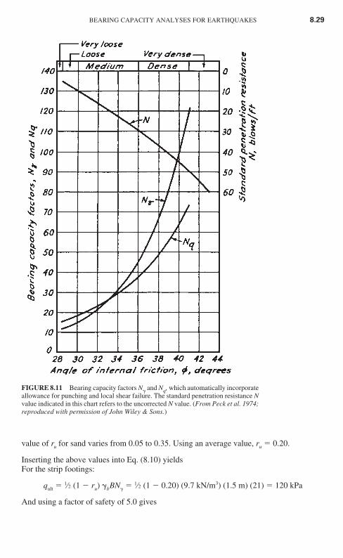
B � width of footing, ft or mN� � bearing capacity factor (dimensionless). Figure 8.11 presents a chart that can be
used to determine the value of N� based on the effective friction angle �′ of thegranular soil.
8.3.3 Example Problem
This example problem illustrates the use of Eq. (8.10). A site consists of a sand depositwith a fluctuating groundwater table. The proposed development will consist of build-ings having shallow strip footings to support bearing walls and interior spread footingsto support isolated columns. The expected depth of the footings will be 0.5 to 1.0 m.Assume that the groundwater table could periodically rise to a level that is close to thebottom of the footings. Also assume the following parameters: buoyant unit weight ofthe sand is 9.7 kN/m3, the sand below the groundwater table has a factor of safetyagainst liquefaction of 1.3, the effective friction angle of the sand �′ � 32°, and thefootings will have a minimum width of 1.5 and 2.5 m for the strip and spread footings,respectively. Using a factor of safety of 5, determine the allowable bearing capacity ofthe footings.
Solution. We use the following values:
�b � 9.7 kN/m3
N� � 21 entering Fig. 8.11 with �′ � 32° and intersecting N� curve, the value of N� from the vertical axis is 21
B � 1.5 m for strip footings and 2.5 m for spread footings
ru � 0.20 entering Fig. 5.15 with a factor of safety against liquefaction of 1.3,
8.28 CHAPTER EIGHT
Ch08_DAY 10/26/01 2:07 PM Page 8.28
value of ru for sand varies from 0.05 to 0.35. Using an average value, ru � 0.20.
Inserting the above values into Eq. (8.10) yieldsFor the strip footings:
qult � 1⁄2 (1 � ru) �bBN� � 1⁄2 (1 � 0.20) (9.7 kN/m3) (1.5 m) (21) � 120 kPa
And using a factor of safety of 5.0 gives
BEARING CAPACITY ANALYSES FOR EARTHQUAKES 8.29
FIGURE 8.11 Bearing capacity factors N� and Nq, which automatically incorporateallowance for punching and local shear failure. The standard penetration resistance Nvalue indicated in this chart refers to the uncorrected N value. (From Peck et al. 1974;reproduced with permission of John Wiley & Sons.)
Ch08_DAY 10/26/01 2:07 PM Page 8.29
qall � � � 24 kPa
For the spread footings:
qult � 0.4 (1 � ru) �bBN� � 0.4 (1 � 0.20) (9.7 kN/m3) (2.5 m) (21) � 160 kPa
And using a factor of safety of 5.0 gives
qall � � � 32 kPa
Thus provided the strip and spread footings are at least 1.5 and 2.5 m wide, respectively,the allowable bearing capacity is equal to 24 kPa for the strip footings and 32 kPa for thespread footings. These allowable bearing pressures would be used to determine the size ofthe footings based on the anticipated dead, live, and seismic loads.
8.4 BEARING CAPACITY ANALYSIS FORCOHESIVE SOIL WEAKENED BY THEEARTHQUAKE
8.4.1 Introduction
As discussed in Sec. 5.5.1, cohesive soils and organic soils can also be susceptible to a lossof shear strength during the earthquake. Examples include sensitive clays, which lose shearstrength when they are strained back and forth. In dealing with such soils, it is often desir-able to limit the stress exerted by the footing during the earthquake so that it is less than themaximum past pressure �vm′ of the cohesive or organic soils. This is to prevent the soil fromsqueezing out or deforming laterally from underneath the footing.
8.4.2 Bearing Capacity Equation
As mentioned in Sec. 7.5, it is often very difficult to predict the amount of earthquake-induced settlement for foundations bearing on cohesive and organic soils. One approach isto ensure that the foundation has an adequate factor of safety in terms of a bearing capac-ity failure. To perform a bearing capacity analysis, a total stress analysis can be performedby assuming that c � su. Using Eq. (8.6), and for a relatively constant undrained shearstrength versus depth below the footing, the ultimate bearing capacity is as follows:For strip footings:
qult � cNc � 5.5su (8.11a)
For spread footings:
qult � cNc �1 0.3 � � 5.5su �1 0.3 � (8.11b)
For a given footing size, the only unknown in Eq. (8.11) is the undrained shear strength su.Table 5.4 presents guidelines in terms of the undrained shear strength that should be uti-
BL
BL
160 kPa
5.0
qultFS
120 kPa
5.0
qultFS
8.30 CHAPTER EIGHT
Ch08_DAY 10/26/01 2:07 PM Page 8.30
lized for earthquake engineering analyses. These guidelines for the selection of theundrained shear strength su as applied to bearing capacity analyses are as follows:
1. Cohesive soil above the groundwater table: Often the cohesive soil above thegroundwater table will have negative pore water pressures due to capillary tension of thepore water fluid. In some cases, the cohesive soil may even be dry and desiccated. The cap-illary tension tends to hold together the soil particles and to provide additional shearstrength to the soil. For the total stress analysis, the undrained shear strength su of the cohe-sive soil could be determined from unconfined compression tests or vane shear tests.
Because of the negative pore water pressures, a future increase in water content wouldtend to decrease the undrained shear strength su of partially saturated cohesive soil abovethe groundwater table. Thus a possible change in water content in the future should be con-sidered. In addition, an unconfined compression test performed on a partially saturatedcohesive soil often has a stress-strain curve that exhibits a peak shear strength which thenreduces to an ultimate value. If there is a significant drop-off in shear strength with strain,it may be prudent to use the ultimate value in the bearing capacity analysis.
2. Cohesive soil below the groundwater table having low sensitivity: The sensitivitySt of a cohesive soil is defined as the undrained shear strength of an undisturbed soil spec-imen divided by the undrained shear strength of a completely remolded soil specimen. Thesensitivity thus represents the loss of undrained shear strength as a cohesive soil specimenis remolded. An earthquake also tends to shear a cohesive soil back and forth, much as theremolding process does. For cohesive soil having low sensitivity (St � 4), the reduction inthe undrained shear strength during the earthquake should be small. Thus the undrainedshear strength from the unconfined compression test or vane shear tests could be used inthe bearing capacity analysis (for field vane tests, consider a possible reduction in shearstrength due to strain rate and anisotropy effects, see Table 7.13 in Day 2000).
3. Cohesive soil below the groundwater table having a high sensitivity: For highlysensitive and quick clays (St � 8), the earthquake-induced ground shaking will tend toshear the soil back and forth, much as the remolding process does. For these types of soils,there could be a significant shear strength loss during the earthquake shaking.
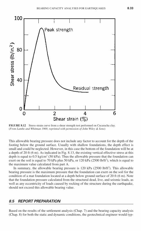
The stress-strain curve from an unconfined compression test performed on a highly sen-sitive or quick clay often exhibits a peak shear strength that develops at a low vertical strain,followed by a dramatic drop-off in strength with continued straining of the soil specimen.An example of this type of stress-strain curve is shown in Fig. 8.12. The analysis will needto include the estimated reduction in undrained shear strength due to the earthquake shak-ing. In general, the most critical conditions exist when the highly sensitive or quick clay issubjected to a high static shear stress (such as the high bearing pressure acting on the soil).If, during the earthquake, the sum of the static shear stress and the seismic induced shearstress exceeds the undrained shear strength of the soil, then a significant reduction in shearstrength is expected to occur.
Cohesive soils having a medium sensitivity (4 � St � 8) tend to be an intermediate case.
Some of the other factors that may need to be considered in the bearing capacity analy-sis are as follows:
1. Earthquake parameters: The nature of the design earthquake, such as the peak groundacceleration amax and earthquake magnitude, is a factor. The higher the peak groundacceleration and the higher the magnitude of the earthquake, the greater the tendencyfor the cohesive soil to be strained and remolded by the earthquake shaking.
2. Soil behavior: As mentioned above, the important soil properties for the bearing
BEARING CAPACITY ANALYSES FOR EARTHQUAKES 8.31
Ch08_DAY 10/26/01 2:07 PM Page 8.31
capacity analysis are the undrained shear strength su, sensitivity St, maximum past pres-sure �vm′ , and the stress-strain behavior of the soil (e.g., Fig. 8.12).
3. Rocking: The increase in shear stress caused by the dynamic loads acting on the foun-dation must be considered in the analysis. Lightly loaded foundations tend to producethe smallest dynamic loads, while heavy and tall buildings subject the foundation tohigh dynamic loads due to rocking.
Given the many variables as outlined above, it takes considerable experience and judg-ment in the selection of the undrained shear strength su to be used in Eq. (8.11).
8.4.3 Example Problem
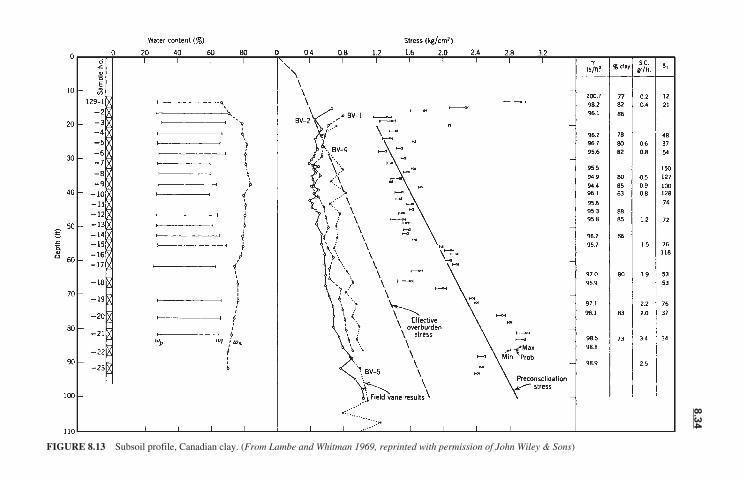
This example problem illustrates the use of Eq. (8.13). Assume that a site has a subsoil pro-file shown in Fig. 8.13. Suppose that a tall building will be constructed at the site. In addi-tion, during the life of the structure, it is anticipated that the building will be subjected tosignificant earthquake-induced ground shaking.
Because of the desirability of underground parking, a mat foundation will be con-structed such that the bottom of the mat is located at a depth of 20 ft (6 m) below groundsurface. Assuming that the mat foundation will be 100 ft long and 100 ft wide (30 m by 30m), determine the allowable bearing pressure that the mat foundation can exert on theunderlying clay layer. Further assume that the clay below the bottom of the mat will not bedisturbed (i.e., lose shear strength) during construction of the foundation.
Solution. Based on the sensitivity values St listed in Fig. 8.11, this clay would be classi-fied as a quick clay. The analysis has been divided into two parts.
Part A. To prevent the soil from being squeezed out or deforming laterally fromunderneath the foundation due to rocking of the structure during the earthquake, the allow-able bearing pressure should not exceed the maximum past pressure (also known as the pre-consolidation stress). Recognizing that the building pressure will decrease with depth, thecritical condition is just below the bottom of the foundation (i.e., depth � 20 ft). At a depthof 20 ft (6 m), the preconsolidation stress is about 1.2 kg/cm2 (2500 lb/ft2), and it increaseswith depth. Thus the allowable bearing pressure should not exceed 120 kPa (2500 lb/ft2).
Part B. The next step is to consider a bearing capacity failure. As indicated in Fig. 8.13,the average undrained shear strength su from field vane shear tests below a depth of 20 ft (6 m)is about 0.6 kg/cm2 (1200 lb/ft2). Field vane shear tests tend to overestimate the undrainedshear strength because of the fast strain rate and anisotropy effects, and thus a correction shouldbe applied. Using Bjerrum’s (1972) recommended correction (see Fig. 7.19 of Day 2000), thecorrection factor � 0.85 for a plasticity index � 40 (the plasticity index is from Fig. 8.13,where the liquid limit wl is about 65 and the plastic limit wp is about 25). Thus the correctedundrained shear strength is equal to 0.6 kg/cm2 times 0.85, or su � 0.5 kg/cm2 (50 kPa).
Using Eq. (8.11b) gives
qult � 5.5su �1 0.3 � � 7.1su � (7.1) (50 kPa) � 350 kPa
Using a factor of safety of 5.0 to account for the possibility of a loss of shear strengthduring the earthquake yields
qall � � � 70 kPa or 1400 lb/ft2350 kPa
5.0
qultFS
BL
8.32 CHAPTER EIGHT
Ch08_DAY 10/26/01 2:07 PM Page 8.32
This allowable bearing pressure does not include any factor to account for the depth of thefooting below the ground surface. Usually with shallow foundations, the depth effect issmall and could be neglected. However, in this case the bottom of the foundation will be ata depth of 20 ft (6 m). As indicated in Fig. 8.13, the existing vertical effective stress at thisdepth is equal to 0.5 kg/cm2 (50 kPa). Thus the allowable pressure that the foundation canexert on the soil is equal to 70 kPa plus 50 kPa, or 120 kPa (2500 lb/ft2), which is equal tothe maximum value calculated from part A.
In summary, the allowable bearing pressure is 120 kPa (2500 lb/ft2). This allowablebearing pressure is the maximum pressure that the foundation can exert on the soil for thecondition of a mat foundation located at a depth below ground surface of 20 ft (6 m). Notethat the foundation pressure calculated from the structural dead, live, and seismic loads, aswell as any eccentricity of loads caused by rocking of the structure during the earthquake,should not exceed this allowable bearing value.
8.5 REPORT PREPARATION
Based on the results of the settlement analysis (Chap. 7) and the bearing capacity analysis(Chap. 8) for both the static and dynamic conditions, the geotechnical engineer would typ-
BEARING CAPACITY ANALYSES FOR EARTHQUAKES 8.33
FIGURE 8.12 Stress-strain curve from a shear strength test performed on Cucaracha clay.(From Lambe and Whitman 1969, reprinted with permission of John Wiley & Sons)
Ch08_DAY 10/26/01 2:07 PM Page 8.33
8.3
4
FIGURE 8.13 Subsoil profile, Canadian clay. (From Lambe and Whitman 1969, reprinted with permission of John Wiley & Sons)
Ch08_DAY 10/26/01 2:07 PM Page 8.34
ically provide design recommendations such as the minimum footing dimensions, embed-ment requirements, and allowable bearing capacity values. These recommendations wouldnormally be included in a soils report. Appendix D presents an example of a geotechnicalengineering report.
An example of typical wording for a bearing material that is not expected to be weak-ened by the earthquake is as follows:
The subject site consists of intact Mission Valley formation (siltstone and sandstone)bedrock. For the static design condition, the allowable bearing pressure for spread footings is8000 lb/ft2 (400 kPa) provided that the footing is at least 5 ft (1.5 m) wide with a minimum of2-ft (0.6-m) embedment in firm, intact bedrock. For continuous wall footings, the allowablebearing pressure is 4000 lb/ft2 (200 kPa) provided the footing is at least 2 ft (0.6 m) wide witha minimum of 2-ft (0.6-m) embedment in firm, intact bedrock. It is recommended that the struc-tures be entirely supported by bedrock.
Because of cut-fill transition conditions, it is anticipated that piers will be needed for theadministrative building. Belled piers can be designed for an allowable end-bearing pressure of12,000 lb/ft2 (600 kPa) provided that the piers have a diameter of at least 2 ft (0.6 m), length ofat least 10 ft (3 m), with a minimum embedment of 3 ft (0.9 m) in firm, intact bedrock. It is rec-ommended that the geotechnical engineer observe pier installation to confirm embedmentrequirements.
In designing to resist lateral loads, passive resistance of 1200 lb/ft2 per foot of depth (200kPa per meter of depth) to a maximum value of 6000 lb/ft2 per foot of depth (900 kPa per meterof depth) and a coefficient of friction equal to 0.35 may be utilized for embedment within firmbedrock.
For the analysis of earthquake loading, the above values of allowable bearing pressure andpassive resistance may be increased by a factor of one-third. This material is not expected tobe weakened by the earthquake-induced ground motion.
An example of typical wording for a bearing material that is expected to be weakenedby the earthquake is as follows:
The subject site consists of a 10-ft-thick upper layer of cohesive soil that is underlain by a15-ft-thick layer of submerged loose sand. Based on our analysis, it is anticipated that the 15-ft-thick sand layer will liquefy during the design earthquake. Since the site is essentially level,lateral movement due to a liquefaction-induced flow failure or lateral spreading is not antici-pated to occur. In addition, the upper 10-ft-thick clay layer should be adequate to prevent liq-uefaction-induced ground damage (i.e., sand boils, surface fissuring, etc.).
It is our recommendation that the lightly loaded structures be supported by the 10-ft-thickupper cohesive soil layer. For the design condition of lightly loaded shallow foundations, theallowable bearing pressure is 1000 lb/ft2 (50 kPa). It is recommended that the shallow footingsbe embedded at a depth of 1 ft (0.3 m) below ground surface and be at least 1 ft (0.3 m) wide.
It is anticipated that piles or piers will be needed for the heavily loaded industrial building.The piles or piers should be founded in the unliquefiable soil stratum which is located at a depthof 25 ft. The piles or piers can be designed for an allowable end-bearing pressure of 4000 lb/ft2
(200 kPa), provided that the piles or piers have a diameter of at least 1 ft (0.3 m) and are embed-ded at least 5 ft (1.5 m) into the unliquefiable soil strata. It is recommended that the geotech-nical engineer observe pile and pier installation to confirm embedment requirements. The pilesor piers should also be designed for down-drag loads during the anticipated earthquake-induced liquefaction of the loose sand layer.
In designing to resist lateral loads, the upper 10-ft-thick clay layer can provide passiveresistance of 100 lb/ft2 per foot of depth (equivalent fluid pressure). For seismic analysis, theunderlying 15-ft-thick sand layer should be assumed to have zero passive resistance.
The above values of allowable bearing pressure and passive resistance should not beincreased for the earthquake conditions. As previously mentioned, the loose sand layer from adepth of 10 to 25 ft below ground surface is expected to liquefy during the design earthquake(i.e., weakened soil conditions).
BEARING CAPACITY ANALYSES FOR EARTHQUAKES 8.35
Ch08_DAY 10/26/01 2:07 PM Page 8.35

8.6 PROBLEMS
The problems have been divided into basic categories as indicated below.
Bearing Capacity for Shallow Foundations Underlain by Liquefied Soil
8.1 Use the data from the example problem for the cohesive surface layer in Sec.8.2.2. Calculate the spread footing size so that the factor of safety is equal to 5. Answer: 5-m by 5-m spread footing.
8.2 Use the data from the example problem for the cohesive surface layer in Sec.8.2.2. Calculate the maximum concentric load that can be exerted to the 2-m by 2-m spreadfooting such that the factor of safety is equal to 5. Answer: P � 200 kN.
8.3 Use the data from the example problem for the cohesionless surface layer in Sec.8.2.2. Calculate the maximum concentric load that can be exerted to the strip footing suchthat the factor of safety is equal to 5. Answer: P � 10 kN/m.
8.4 Use the data from the example problem for the cohesionless surface layer in Sec.8.2.2. Calculate the maximum concentric load that can be exerted to the 2-m by 2-m spreadfooting such that the factor of safety is equal to 5. Answer: P � 40 kN.
8.5 Use the data from Prob. 6.12 and the subsoil profile shown in Fig. 6.13. Assumethe following: Peak ground acceleration is equal to 0.20g, the groundwater table is unlikelyto rise above its present level, a 1.5-m-thick fill layer will be constructed at the site, the soilabove the groundwater table (including the proposed fill layer) is sand with an effectivefriction angle �′ equal to 33° and k0 � 0.5, and the foundation will consist of shallow stripand spread footings that are 0.3 m deep. Using a factor of safety equal to 5 and footingwidths of 1 m, determine the allowable bearing pressure for the strip and spread footings.Answer: qall � 10 kPa for 1-m-wide strip footings and qall � 20 kPa for 1-m by 1-m spreadfootings.
8.6 Solve Prob. 8.5, except assume that the soil above the groundwater table (includ-ing the proposed fill layer) is cohesive soil that has undrained shear strength of 20 kPa.Answer: qall � 20 kPa for the 1-m-wide strip footings, and qall � 40 kPa for the 1-m by 1-mspread footings.
8.7 Solve Prob. 8.5, using the Terzaghi bearing capacity equation. What values shouldbe used in the design of the footings? Answer: qall � 48 kPa for the 1-m-wide strip footings,and qall � 38 kPa for the 1-m by 1-m spread footings. For the design of the footings, use thelower values calculated in Prob. 8.5.
8.8 Solve Prob. 8.6, using the Terzaghi bearing capacity equation. What values shouldbe used in the design of the footings? Answer: qall � 22 kPa for the 1-m-wide strip footings,and qall � 30 kPa for the 1-m by 1-m spread footings. For the design of the strip footings,use the value from Prob. 8.6 (qall � 20 kPa). For the design of the spread footings, use thelower value calculated in this problem (qall � 30 kPa).
8.9 Solve Prob. 8.6, assuming that the spread footing is 3 m by 3 m. Use the methodsoutlined in Secs. 8.2.2 and 8.2.3. What bearing capacity values should be used in the designof the footings? Answer: From Eq. (8.1), qall � 14 kPa. From the method in Sec. 8.2.3, qall� 12 kPa. Use the lower value of 12 kPa for the design of the 3-m by 3-m spread footing.
Bearing Capacity for Deep Foundations Underlain by Liquefied Soil
8.10 Use the data from Prob. 6.12 and Fig. 6.13. Assume that a 20-m by 20-m matfoundation is supported by piles, with the tip of the piles located at a depth of 15 m. The
8.36 CHAPTER EIGHT
Ch08_DAY 10/26/01 2:07 PM Page 8.36
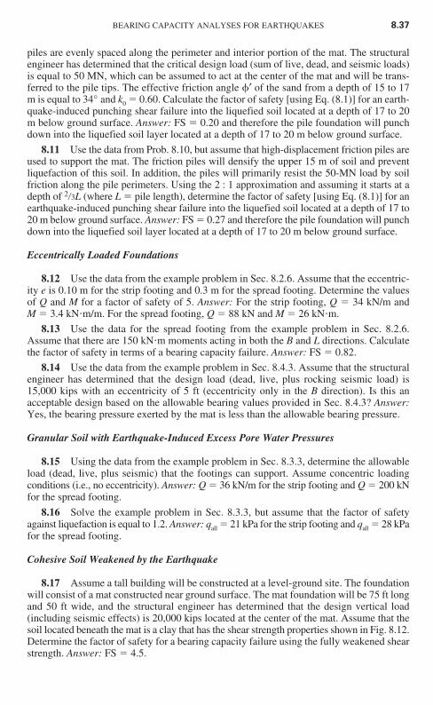
piles are evenly spaced along the perimeter and interior portion of the mat. The structuralengineer has determined that the critical design load (sum of live, dead, and seismic loads)is equal to 50 MN, which can be assumed to act at the center of the mat and will be trans-ferred to the pile tips. The effective friction angle �′ of the sand from a depth of 15 to 17m is equal to 34° and k0 � 0.60. Calculate the factor of safety [using Eq. (8.1)] for an earth-quake-induced punching shear failure into the liquefied soil located at a depth of 17 to 20m below ground surface. Answer: FS � 0.20 and therefore the pile foundation will punchdown into the liquefied soil layer located at a depth of 17 to 20 m below ground surface.
8.11 Use the data from Prob. 8.10, but assume that high-displacement friction piles areused to support the mat. The friction piles will densify the upper 15 m of soil and preventliquefaction of this soil. In addition, the piles will primarily resist the 50-MN load by soilfriction along the pile perimeters. Using the 2 : 1 approximation and assuming it starts at adepth of 2�3L (where L � pile length), determine the factor of safety [using Eq. (8.1)] for anearthquake-induced punching shear failure into the liquefied soil located at a depth of 17 to20 m below ground surface. Answer: FS � 0.27 and therefore the pile foundation will punchdown into the liquefied soil layer located at a depth of 17 to 20 m below ground surface.
Eccentrically Loaded Foundations
8.12 Use the data from the example problem in Sec. 8.2.6. Assume that the eccentric-ity e is 0.10 m for the strip footing and 0.3 m for the spread footing. Determine the valuesof Q and M for a factor of safety of 5. Answer: For the strip footing, Q � 34 kN/m and M � 3.4 kN m/m. For the spread footing, Q � 88 kN and M � 26 kN m.
8.13 Use the data for the spread footing from the example problem in Sec. 8.2.6.Assume that there are 150 kN m moments acting in both the B and L directions. Calculatethe factor of safety in terms of a bearing capacity failure. Answer: FS � 0.82.
8.14 Use the data from the example problem in Sec. 8.4.3. Assume that the structuralengineer has determined that the design load (dead, live, plus rocking seismic load) is15,000 kips with an eccentricity of 5 ft (eccentricity only in the B direction). Is this anacceptable design based on the allowable bearing values provided in Sec. 8.4.3? Answer:Yes, the bearing pressure exerted by the mat is less than the allowable bearing pressure.
Granular Soil with Earthquake-Induced Excess Pore Water Pressures
8.15 Using the data from the example problem in Sec. 8.3.3, determine the allowableload (dead, live, plus seismic) that the footings can support. Assume concentric loadingconditions (i.e., no eccentricity). Answer: Q � 36 kN/m for the strip footing and Q � 200 kNfor the spread footing.
8.16 Solve the example problem in Sec. 8.3.3, but assume that the factor of safetyagainst liquefaction is equal to 1.2. Answer: qall � 21 kPa for the strip footing and qall � 28 kPafor the spread footing.
Cohesive Soil Weakened by the Earthquake
8.17 Assume a tall building will be constructed at a level-ground site. The foundationwill consist of a mat constructed near ground surface. The mat foundation will be 75 ft longand 50 ft wide, and the structural engineer has determined that the design vertical load(including seismic effects) is 20,000 kips located at the center of the mat. Assume that thesoil located beneath the mat is a clay that has the shear strength properties shown in Fig. 8.12.Determine the factor of safety for a bearing capacity failure using the fully weakened shearstrength. Answer: FS � 4.5.
BEARING CAPACITY ANALYSES FOR EARTHQUAKES 8.37
Ch08_DAY 10/26/01 2:07 PM Page 8.37
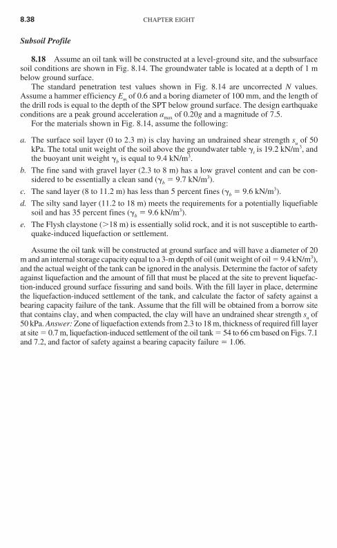
Subsoil Profile
8.18 Assume an oil tank will be constructed at a level-ground site, and the subsurfacesoil conditions are shown in Fig. 8.14. The groundwater table is located at a depth of 1 mbelow ground surface.
The standard penetration test values shown in Fig. 8.14 are uncorrected N values.Assume a hammer efficiency Em of 0.6 and a boring diameter of 100 mm, and the length ofthe drill rods is equal to the depth of the SPT below ground surface. The design earthquakeconditions are a peak ground acceleration amax of 0.20g and a magnitude of 7.5.
For the materials shown in Fig. 8.14, assume the following:
a. The surface soil layer (0 to 2.3 m) is clay having an undrained shear strength su of 50kPa. The total unit weight of the soil above the groundwater table �t is 19.2 kN/m3, andthe buoyant unit weight �b is equal to 9.4 kN/m3.
b. The fine sand with gravel layer (2.3 to 8 m) has a low gravel content and can be con-sidered to be essentially a clean sand (�b � 9.7 kN/m3).
c. The sand layer (8 to 11.2 m) has less than 5 percent fines (�b � 9.6 kN/m3).
d. The silty sand layer (11.2 to 18 m) meets the requirements for a potentially liquefiablesoil and has 35 percent fines (�b � 9.6 kN/m3).
e. The Flysh claystone (�18 m) is essentially solid rock, and it is not susceptible to earth-quake-induced liquefaction or settlement.
Assume the oil tank will be constructed at ground surface and will have a diameter of 20m and an internal storage capacity equal to a 3-m depth of oil (unit weight of oil � 9.4 kN/m3),and the actual weight of the tank can be ignored in the analysis. Determine the factor of safetyagainst liquefaction and the amount of fill that must be placed at the site to prevent liquefac-tion-induced ground surface fissuring and sand boils. With the fill layer in place, determinethe liquefaction-induced settlement of the tank, and calculate the factor of safety against abearing capacity failure of the tank. Assume that the fill will be obtained from a borrow sitethat contains clay, and when compacted, the clay will have an undrained shear strength su of50 kPa. Answer: Zone of liquefaction extends from 2.3 to 18 m, thickness of required fill layerat site � 0.7 m, liquefaction-induced settlement of the oil tank � 54 to 66 cm based on Figs. 7.1and 7.2, and factor of safety against a bearing capacity failure � 1.06.
8.38 CHAPTER EIGHT
Ch08_DAY 10/26/01 2:07 PM Page 8.38
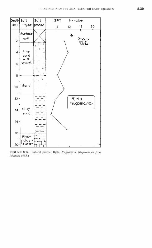
BEARING CAPACITY ANALYSES FOR EARTHQUAKES 8.39
FIGURE 8.14 Subsoil profile, Bjela, Yugoslavia. (Reproduced fromIshihara 1985.)
Ch08_DAY 10/26/01 2:07 PM Page 8.39