Embed Size (px)
Citation preview
© Carl Ross, John Bird & Andrew Little Published by Taylor and Francis
CHAPTER 8 TORSION
EXERCISE 37, Page 174
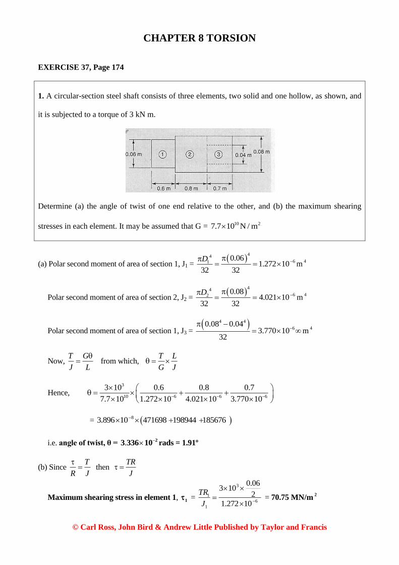
1. A circular-section steel shaft consists of three elements, two solid and one hollow, as shown, and
it is subjected to a torque of 3 kN m.
Determine (a) the angle of twist of one end relative to the other, and (b) the maximum shearing
stresses in each element. It may be assumed that G = 10 27.7 10 N / m
(a) Polar second moment of area of section 1, J1 =
4461
0.061.272 10
32 32
D
m4
Polar second moment of area of section 2, J2 =
4462
0.084.021 10
32 32
D
m4
Polar second moment of area of section 1, J3 = 4 4
60.08 0.04
3.770 1032
m4
Now, T G
J L
from which,
T L
G J
Hence, 3
10 6 6 6
3 10 0.6 0.8 0.7
7.7 10 1.272 10 4.021 10 3.770 10
= 83.896 10 471698 198944 185676
i.e. angle of twist, θ = . 23 336 10 rads = 1.91º
(b) Since T
R J
then
TR
J
Maximum shearing stress in element 1, 1 =
3
1
6
1
0.063 10
2
1.272 10
TR
J
= 70.75 MN/m2

© Carl Ross, John Bird & Andrew Little Published by Taylor and Francis
Maximum shearing stress in element 2, 2 =
3
2
6
2
0.083 10
2
4.021 10
TR
J
= 29.84 MN/m2
Maximum shearing stress in element 3, 3 =
3
3
6
3
0.083 10
2
3.770 10
TR
J
= 31.83 MN/m2
2. A circular-section steel shaft consists of three elements, two solid and one hollow, as shown in
the diagram in Problem 1, and it is subjected to a torque of 4 kN m. Determine (a) the angle of twist
of one end relative to the other, and (b) the maximum shearing stresses in each element. It may be
assumed that G = 10 27.7 10 N / m .
(a) Polar second moment of area of section 1, J1 =
4461
0.061.272 10
32 32
D
m4
Polar second moment of area of section 2, J2 =
4462
0.084.021 10
32 32
D
m4
Polar second moment of area of section 1, J3 = 4 4
60.08 0.04
3.770 1032
m4
Now, T G
J L
from which,
T L
G J
Hence, 3
10 6 6 6
4 10 0.6 0.8 0.7
7.7 10 1.272 10 4.021 10 3.770 10
= 85.195 10 471698 198944 185676
i.e. angle of twist, θ = . 24 448 10 rads = 2.55º
(b) Since T
R J
then
TR
J
Maximum shearing stress in element 1, 1 =
3
1
6
1
0.064 10
2
1.272 10
TR
J
= 94.34 MN/m2

© Carl Ross, John Bird & Andrew Little Published by Taylor and Francis
Maximum shearing stress in element 2, 2 =
3
2
6
2
0.084 10
2
4.021 10
TR
J
= 39.79 MN/m2
Maximum shearing stress in element 3, 3 =
3
3
6
3
0.084 10
2
3.770 10
TR
J
= 42.44 MN/m2
3. If the shaft of Problem 1 were constructed from three separate materials, namely steel in element
(1), aluminium alloy in element (2) and manganese bronze in element (3), determine (a) the total
angle of twist, and (b) the maximum shearing stresses in each element. Assume that
10 2
1G 7.7 10 N / m , 10 2
2G 2.5 10 N / m and 10 2
3G 3.9 10 N / m .
Since T L
G J
then 3 3 3
10 6 10 6 10 6
3 10 0.6 3 10 0.8 3 10 0.7
7.7 10 1.272 10 2.5 10 4.021 10 3.9 10 3.770 10
= 0.0184 + 0.0239 + 0.0143
i.e. angle of twist, θ = 0.0566 rads = 3.24º
Maximum shearing stress in element 1, 1 =
3
1
6
1
0.063 10
2
1.272 10
TR
J
= 70.75 MN/m2
Maximum shearing stress in element 2, 2 =
3
2
6
2
0.083 10
2
4.021 10
TR
J
= 29.84 MN/m2
Maximum shearing stress in element 3, 3 =
3
3
6
3
0.083 10
2
3.770 10
TR
J
= 31.83 MN/m2

© Carl Ross, John Bird & Andrew Little Published by Taylor and Francis
4. If the shaft of Problem 2 were constructed from three separate materials, namely steel in element
(1), aluminium alloy in element (2) and manganese bronze in element (3), determine (a) the total
angle of twist, and (b) the maximum shearing stresses in each element. Assume that
10 2
1G 7.7 10 N / m , 10 2
2G 2.5 10 N / m and 10 2
3G 3.9 10 N / m .
(a) Polar second moment of area of section 1, J1 =
4461
0.061.272 10
32 32
D
m4
Polar second moment of area of section 2, J2 =
4462
0.084.021 10
32 32
D
m4
Polar second moment of area of section 1, J3 = 4 4
60.08 0.04
3.770 1032
m4
Now, T G
J L
from which,
T L
G J
Hence, 3 3 3
10 6 10 6 10 6
4 10 0.6 4 10 0.8 4 10 0.7
7.7 10 1.272 10 2.5 10 4.021 10 3.9 10 3.770 10
= 0.0245 + 0.0318 + 0.0190
i.e. angle of twist, θ = 0.0753 rads = 4.314º
(b) Since T
R J
then
TR
J
Maximum shearing stress in element 1, 1 =
3
1
6
1
0.064 10
2
1.272 10
TR
J
= 94.34 MN/m2
Maximum shearing stress in element 2, 2 =
3
2
6
2
0.084 10
2
4.021 10
TR
J
= 39.79 MN/m2
Maximum shearing stress in element 3, 3 =
3
3
6
3
0.084 10
2
3.770 10
TR
J
= 42.44 MN/m2

© Carl Ross, John Bird & Andrew Little Published by Taylor and Francis
5. Determine the output torque of an electric motor which supplies 5 kW at 25 rev/s.
(a) If this torque is transmitted through a tube of external diameter 20 mm, determine the internal
diameter if the maximum permissible shearing stress in the shaft is 35 MN/m2
.
(b) If this shaft is to be connected to another one, via a flanged coupling, determine a suitable bolt
diameter if four bolts are used on a pitch circle diameter of 30 mm, and the maximum permissible
shearing stresses in the bolts equal 45 MN/m2
.
(a) ω = 2 π × 25 = 157.1 Hz
Tω = Power
from which, torque, T = 35 10
157.1
P
= 31.83 N m
Now, T
r J
i.e.
6
4 4
35 10 31.83
0.020.01
2 2r
12
i.e. 8 4 9
6
31.83 0.011 10 5.7896 10
35 102
r
and 4 8 9 91 10 5.7896 10 4.210 10r
from which, 9 34 4.210 10 8.055 10r m = 8.055 mm
Hence, the internal diameter, d = 16.11 mm, say, 16 mm
(b) For the bolts:
δF = 2 2
6 6 245 10 35.34 104 4
F
d dd
3
Torque, T = n × δF × R = 4 × 6 235.34 10 0.015d
= 6 22.1204 10 d = 31.83 from part (a)

© Carl Ross, John Bird & Andrew Little Published by Taylor and Francis
and the bolt diameter, d = 3
6
31.833.87 10
2.1204 10
m = 3.87 mm, say, 4 mm
6. Determine the output torque of an electric motor which supplies 8 kW at 25 rev/s.
(a) If this torque is transmitted through a tube of external diameter 22 mm, determine the internal
diameter if the maximum permissible shearing stress in the shaft is 35 MN/m2
.
(b) If this shaft is to be connected to another one, via a flanged coupling, determine a suitable bolt
diameter if four bolts are used on a pitch circle diameter of 32 mm, and the maximum permissible
shearing stresses in the bolts equal 45 MN/m2
.
(a) ω = 2 π × 25 = 157.08 Hz
Tω = Power
from which, torque, T = 38 10
157.08
P
= 50.93 N m
Now, T
r J
i.e.
6
4 4
35 10 50.92
0.0220.011
2 2r
45
i.e. 8 4 8
6
50.92 0.0111.464 10 1.0188 10
35 102
r
and 4 8 8 91.464 10 1.0188 10 4.452 10r
from which, 9 34 4.452 10 8.168 10r m = 8.168 mm
Hence, the internal diameter, d = 16.34 mm, say, 16.5 mm
(b) For the bolts:
δF = 2 2
6 6 245 10 35.34 104 4
F
d dd
Torque, T = n × δF × R = 4 × 6 235.34 10 0.016d

© Carl Ross, John Bird & Andrew Little Published by Taylor and Francis
= 6 22.2618 10 d = 50.92 from part (a)
and the bolt diameter, d = 3
6
50.924.745 10
2.2618 10
m = 4.745 mm, say, 5.0 mm

© Carl Ross, John Bird & Andrew Little Published by Taylor and Francis
EXERCISE 38, Page 179
1. A compound shaft consists of two equal length hollow shafts joined together in series and
subjected to a torque T, as shown below. If the shaft on the left is made from steel, and the shaft on
the right of the figure is made from aluminium alloy, determine the maximum permissible value of
T, given the following:
For steel: G = 10 27.7 10 N / m Maximum permissible shear stress = 140 MN/m 2
For aluminium alloy: G = 10 22.6 10 N / m Maximum permissible shear stress = 90 MN/m2
Polar second moment of area of steel section, J1 = 4 4
60.08 0.06
2.749 1032
m4
Polar second moment of area of aluminium section, J2 = 4 4
60.1 0.06
8.545 1032
m4
Now, T
r J
from which,
JT
r
6 6140 10 2.749 10
96210.04
ST
N m = 9.62 kN m
6 690 10 8.545 10
153810.05
aT
N m = 15.38 kN m
The maximum permissible value of T = 9.62 kN m
2. A compound shaft consists of a solid aluminium-alloy cylinder of length 1 m and diameter 0.1 m,
connected in series to a steel tube of the same length and external diameter, and of thickness 0.02
m. The shaft is fixed at its ends and is subjected to an intermediate torque of 9 kN m at the joint.

© Carl Ross, John Bird & Andrew Little Published by Taylor and Francis
Determine the angle of twist and the maximum shear stress in the two halves. Assume that (steel)G =
10 27.7 10 N / m and (Al alloy)G = 10 22.6 10 N / m .
1 1
1 1
c
T l
G J and 2 2
2 2
c
T l
G J
Hence, 1 1 2 2
1 1 2 2
T l T l
G J G J
However, 1 2l l
from which, 2 1 11
2 2
T G JT
G J (1)
Polar second moment of area of aluminium section, Ja =
4461
0.19.8175 10
32 32
D
m4
Polar second moment of area of steel section, Js = 4 4
60.1 0.06
8.5451 1032
m4
10 6
21 210 6
2.6 10 9.817 100.388
7.7 10 8.545 10
TT T
(1a)
3
1 2 9 10T T T (2)
From equation (1a), 3
2 20.388 9 10T T
from which, 2
9000
1.388T = 6484 N m (3)
From equation (1a), 1 0.388 6484T = 2516 N m
Now, T
r J
from which,
T r
J

© Carl Ross, John Bird & Andrew Little Published by Taylor and Francis
Alloy: 1 11 6
1
2516 0.05
9.817 10
T R
J
= 12.81 MPa
Steel: 2 22 6
2
6484 0.05
8.545 10
T R
J
= 37.94 MPa
T G
J l
i.e.
Tl
GJ
Alloy: 1 11 10 6
1 1
2516 1
2.6 10 9.8175 10
T l
G J
= . 3
9 857 10 rad = 0.565º
Steel: 2 22 10 6
2 2
6484 1
7.7 10 8.5451 10
T l
G J
= . 3
9 855 10 rad = 0.565º
3. A compound shaft consists of two elements of equal length, joined together in series. If one
element of the shaft is constructed from gunmetal tube and the other from solid steel, where the
external diameter of the steel shaft and the internal diameter of the gunmetal shaft equal 50 mm,
determine the external diameter of the gunmetal shaft if the two shafts are to have the same
torsional stiffness. Determine also the maximum permissible torque that can be applied to the shaft,
given the following:
For gunmetal: G = 10 23 10 N / m Maximum permissible shear stress = 45 MN/m2
For steel: G = 10 27.5 10 N / m Maximum permissible shear stress = 90 MN/m2
Polar second moment of area of aluminium section, Js =
4471
0.056.136 10
32 32
D
m4
Polar second moment of area of steel section, JG = 4 4
2 0.05
32
Dm
4 (1)

© Carl Ross, John Bird & Andrew Little Published by Taylor and Francis
Now, GJ
l = constant
i.e. s s
s
G J
l = G G
G
G J
l
i.e. 1010 7 3 107.5 10 6.136 10 GJ
l l
and 10 7
6
10
7.5 10 6.136 101.534 10
3 10GJ
From equation (1), 4 4
260.05
1.534 1032
D
Hence, 6
4 4
2
1.534 10 320.05D
i.e. 6 4 4
215.625 10 0.05D
and 4 6 4 5
2 15.625 10 0.05 2.1875 10D
from which, external diameter of gunmetal,
54
2 2.1875 10D = 0.06839 m = 68.4 mm
The maximum permissible torque of gunmetal,
6 645 10 1.534 10
0.025
G GG
G
JT
r
= 2761 N m
The maximum permissible torque of steel,
6 790 10 6.136 10
0.025
s ss
s
JT
r
= 2209 N m
Therefore, maximum permissible torque, T = sT = 2209 N m which is the smallest of the two
torques.
4. A compound shaft consists of a solid steel core, which is surrounded co-axially by aluminium
bronze sheath. Determine suitable values for the diameters of the shafts if the steel core is to carry
two thirds of a total torque of 500 N m and if the limiting stresses are not exceeded.

© Carl Ross, John Bird & Andrew Little Published by Taylor and Francis
For aluminium alloy: G = 10 23.8 10 N / m Maximum permissible shear stress = 18 MN/m 2
For steel: G = 10 27.7 10 N / m Maximum permissible shear stress = 36 MN/m 2
Ts = 2
5003 = 333.3 N m
Tal = 1
5003 = 166.7 N m
Now, T G
J l
Hence, s a
s s a a
T l T l
G J G J
Therefore, 10 10
333.3 166.7
7.7 10 3.8 10s aJ J
from which, 1.0135a sJ J
Now, 4 4
32a
D dJ
and 4
32s
dJ
Hence, 4 4 4
1.013532 32
D d d
i.e. 4 4 41.0135D d d
and 4 42.0135D d
or D = 1.191 d
Now, G
r l

© Carl Ross, John Bird & Andrew Little Published by Taylor and Francis
For steel, 6
10
36 10
7.7 102
s
s s
l l
dG r
and 49.351 10
l d
(1)
For aluminium bronze alloy,
6
10
18 10
3.8 102
a
a a
l l
DG r
and 49.474 10
l D
(2)
From equations (10 and (2), 4 49.351 10 9.474 10
d D
and D = 1.0132 d (3)
The aluminium bronze alloy is the design criterion
4 4 41.191 1
32a
dJ
= 0.0994 4d
Now, a a
a a
T
r J
i.e. 6
4
18 10 166.7
1.191 / 2 0.0994d d
from which, 3 5
6
166.7 1.1915.5483 10
2 0.0994 18 10d
and d = 0.0381 m = 38.1 mm
From equation (3), D = 1.0132 d = 1.0132 × 38.1 = 38.6 mm
5. A compound shaft consists of two equal length hollow shafts joined together in series and
subjected to a torque T, as shown below. If the shaft on the left is made from steel, and the shaft on

© Carl Ross, John Bird & Andrew Little Published by Taylor and Francis
the right of the figure is made from aluminium alloy, determine the maximum permissible value of
T, given the following:
For steel: G = 10 27.7 10 N / m Maximum permissible shear stress = 140 MN/m 2
For aluminium alloy: G = 10 22.6 10 N / m Maximum permissible shear stress = 90 MN/m2
Polar second moment of area of steel section, J1 = 4 4
60.09 0.07
4.084 1032
m4
Polar second moment of area of aluminium section, J2 = 4 4
50.12 0.08
1.634 1032
m4
From equation (1) of Problem (2), 10 6
2
10 5
7.7 10 4.084 10
2.6 10 1.634 10
a s ss
a a
T G J TT
G J
i.e. 0.74s aT T (1)
From equation (2) of Problem 2, s aT T T (2)
From equation (1), 0.74 a aT T T
i.e. 1.74
a
TT = 0.575 T

© Carl Ross, John Bird & Andrew Little Published by Taylor and Francis
Now, T
r J
from which,
JT
r
Alloy: 6 590 10 1.632 10
0.06
a aa
a
JT
R
= 1470.6 N m
Steel: 6 6140 10 4.084 10
0.045
s ss
s
JT
R
= 12706 N m
From equation (1), 12706
0.74 0.74
sa
TT = 17170 N m,
which is impossible as the aluminium alloy tube will fail; thus, aT = 1471 N m is the design
criterion, and from equation (1), sT = 0.74 × 1471 = 1088.5 N m
The maximum permissible value of T = a sT T = 1471 + 1088.5 = 2.56 kN m
6. A compound shaft consists of a solid aluminium-alloy cylinder of length 1 m and diameter 0.1 m,
connected in series to a steel tube of the same length and external diameter, and of thickness 0.02
m. The shaft is fixed at its ends and is subjected to an intermediate torque of 10 kN m at the joint.
Determine the angle of twist and the maximum shear stress in the two halves. Assume that (steel)G =
10 27.7 10 N / m and (Al alloy)G = 10 22.6 10 N / m .
Polar second moment of area of aluminium section, Ja =
4461
0.19.8175 10
32 32
D
m4
Polar second moment of area of steel section, Js = 4 4
60.1 0.06
8.5451 1032
m4
Now, G
r L
from which,
L
G r
Hence, 10 6
1
2.6 10 9.8175 10a
a a aC
a a
T l T
G J
= .
aT
63 918 10
and 10 6
1
7.7 10 8.5451 10s
s s sC
s s
T l T
G J
= .
sT
61 5198 10

© Carl Ross, John Bird & Andrew Little Published by Taylor and Francis
Since a sC C
then 6 63.918 10 1.5198 10a sT T
from which, 3.918
1.5198s aT T i.e. .s aT T2 578
Now, 310 10s aT T (1)
i.e. 2.578 a aT T = 10000
i.e. 10000
3.578aT = 2.795 kN m
From equation (1), 3 310 10 2.795 10sT = 7.205 kN m
Angle of twist, C = 6 33.918 10 2.795 10 = 0.01095 rad = 0.627º
Shear stress in the aluminium alloy, τal = 3
6
2.795 10 0.05
9.8175 10
a
a
T r
J
= 14.23 MN/m
2
Shear stress in the steel, τsteel = 3
6
7.205 10 0.05
8.5451 10
s
s
T r
J
= 42.16 MN/m
2
7. A compound shaft consists of two elements of equal length, joined together in series. If one
element of the shaft is constructed from gunmetal tube and the other from solid steel, where the
external diameter of the steel shaft and the internal diameter of the gunmetal shaft equal 60 mm,
determine the external diameter of the gunmetal shaft if the two shafts are to have the same
torsional stiffness. Determine also the maximum permissible torque that can be applied to the shaft,
given the following:
For gunmetal: G = 10 23 10 N / m Maximum permissible shear stress = 45 MN/m2
For steel: G = 10 27.5 10 N / m Maximum permissible shear stress = 90 MN/m2

© Carl Ross, John Bird & Andrew Little Published by Taylor and Francis
From equation (1) of Problem 2, s gm gm
gm
s s
T G JT
G J (1)
44 3
4 5
60 101.296 10
32 32gm
DJ D
i.e. 4 60.098 1.272 10gmJ D m4
(2)
43
660 10
1.272 1032
sJ
m4
Substituting equations (2) into equation (1) gives:
10 4 6
10 6
3 10 0.098 1.272 10
7.5 10 1.272 10
s
gm
T DT
(3)
i.e. 6 42940 10 38160
95400
s
gm
T DT
(4)
Torsional stiffness = k = GJ
l (5)
gm gm s s
gm s
G J G J
l l
However, gm sl l
thus, gm gm s sG J G J
i.e. 10 4 6 10 63 10 0.098 1.272 10 7.5 10 1.272 10D
i.e. 4 6 60.294 3.816 10 9.54 10D
and 6 6
4 9.54 10 3.816 10
0.294D

© Carl Ross, John Bird & Andrew Little Published by Taylor and Francis
and D = 6 6
49.54 10 3.816 10
0.294
= 0.082 m
i.e. the external diameter, D = 82 mm
From equation (4), 6 42940 10 (0.082) 38160
95400
s
gm
TT
132924 38160
95400
sT = 0.9933 sT
6 590 10 1.272 10
0.03
s ss
s
JT
r
= 3816 N m
and 6 645 10 3.122 10
0.041
gm gm
gm
gm
JT
r
= 3427 N m
The design criterion = gmT = 3427 N m
3427
0.9933 0.9933
gm
s
TT = 3450
Therefore, maximum permissible torque, T = 3427 + 3450 = 6877 N m
8. A compound shaft consists of a solid steel core, which is surrounded co-axially by aluminium
bronze sheath. Determine suitable values for the diameters of the shafts if the steel core is to carry
two thirds of a total torque of 700 N m and if the limiting stresses are not exceeded.
For aluminium alloy: G = 10 23.8 10 N / m Maximum permissible shear stress = 18 MN/m2
For steel: G = 10 27.7 10 N / m Maximum permissible shear stress = 36 MN/m2
Total torque, T = 700 N m
2
466.73
sT T N m and 700 233.3a sT T N m
s as
s s a a
T l T l
G J G J i.e. s a
s s a a
T T
G J G J
Hence, 10 10
466.7 233.3
7.7 10 3.8 10s aJ J

© Carl Ross, John Bird & Andrew Little Published by Taylor and Francis
from which, 1.0129a sJ J
4
32s
dJ
and
4 4
32a
D dJ
from which, 4 4 41.0129D d d
i.e. 4 42.0129D d
and D = 1.191d
G
r l
For steel: 6
10
36 10
7.7 10 / 2
s
s s
l l
G r d
i.e. 6 4
10
36 10 2 9.35 10
7.7 10l d d
(1)
For aluminium bronze alloy:
6
10
18 10
3.8 10 / 2
a
a a
l l
G r D
However, D = 1.191d
therefore, 6 4
10
18 10 2 7.954 10
3.8 10 1.191l d d
(2)
From equations (1) and (2), the aluminium bronze alloy is the design criterion.
4 4 4 4 4
41.191 1
0.099432 32
a
D d dJ d
a a
a a
T
r J
i.e.
6
4
18 10 233.3
1.191 / 2 0.0994d d
from which, 6
3 5
6
18 10 233.3 1.1917.7649 10
1.191/ 2 18 10 0.0994 2d
and d = 3 57.7649 10 = 0.0427 m = 42.66 mm
and D = 1.191 d = 50.86 mm
© Carl Ross, John Bird & Andrew Little Published by Taylor and Francis
EXERCISE 39, Page 190
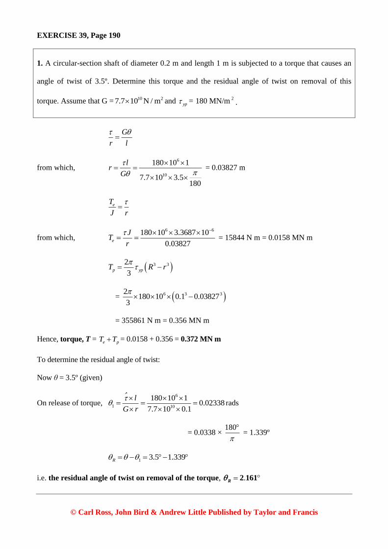
1. A circular-section shaft of diameter 0.2 m and length 1 m is subjected to a torque that causes an
angle of twist of 3.5º. Determine this torque and the residual angle of twist on removal of this
torque. Assume that G = 10 27.7 10 N / m and yp= 180 MN/m
2.
G
r l
from which, 6
10
180 10 1
7.7 10 3.5180
lr
G
= 0.03827 m
eT
J r
from which, 6 6180 10 3.3687 10
0.03827e
JT
r
= 15844 N m = 0.0158 MN m
3 32
3p ypT R r
= 6 3 32180 10 0.1 0.03827
3
= 355861 N m = 0.356 MN m
Hence, torque, T = e pT T = 0.0158 + 0.356 = 0.372 MN m
To determine the residual angle of twist:
Now θ = 3.5º (given)
On release of torque, 6
1 10
180 10 10.02338
7.7 10 0.1
l
G r
rads
= 0.0338 × 180
= 1.339º
1 3.5 1.339R
i.e. the residual angle of twist on removal of the torque, . R
2 161

© Carl Ross, John Bird & Andrew Little Published by Taylor and Francis
2. Determine the maximum possible torque that the cross-section shown below can withstand, given
that yield shear stress = 170 MPa.
What would be the angle of twist per unit length if G = 107.7 10 Pa?
2
T
At
Hence, 6
2170 10
2 0.1 0.2 1 10
T
6
from which, T = 6 2170 10 2 0.1 0.2 1 10
i.e. maximum stress, T = 68000 N m
24
TL ds
A G t
= 4 10 2 2
68000 1 180 0.5 0.1
4 4 10 7.7 10 1 10 2 10
= 0.0316 × 55
i.e. angle of twist, θ = 1.738º
3. Determine the maximum possible torque that the cross-section shown below can withstand given
that yield shear stress = 170 MPa.
What would be the angle of twist per unit length if G = 107.7 10 Pa?

© Carl Ross, John Bird & Andrew Little Published by Taylor and Francis
3 3 3
2 2 23 0.1 1 10 0.2 1 10 0.2 2 10
3 3
btJ
= 7 63 10 1.6 10
3
i.e. . J7
6 333 10 m4
maxmax
T t
J
from which, maximum torque,
6 7
max
2
max
170 10 6.333 10
2 10
JT
t
= 5383 N m
T GJl
from which, angle of twist per unit length,
10 7
5383 180
7.7 10 6.333 10
T
l GJ
= 6.325º/metre
4. A circular-section shaft of diameter 0.25 m and length 1 m is subjected to a torque that causes an
angle of twist of 3.5º. Determine this torque and the residual angle of twist on removal of this
torque. Assume that G = 10 27.7 10 N / m and yp= 180 MN/m
2.

© Carl Ross, John Bird & Andrew Little Published by Taylor and Francis
Radius, R = 0.25/2 = 0.125 m
pR = outer radius of elastic core
T = applied torque = 1e pT T
eT = torsional resistance of elastic core
1pT = torsional resistance of shaded plastic core
eJ = polar 2nd
moment of area of elastic core
yp = shear stress at yield
To calculate θ:
yp e
p e
T G
R J l
where
4
2
p
e
RJ
4
2
yp yp p
e e
p p
RT J
R R
=
4
318090
2
p
p
p
RR
R
i.e. 3282.7e pT R (1)

© Carl Ross, John Bird & Andrew Little Published by Taylor and Francis
From diagram, 1 2p
R
ypp RT rdr r
= 3
22 23p
p
RR
yp ypR
R
rr dr
= 3 32
1803
pR R
However, R = 0.125
hence, 1
3 32180 0.125
3pp
T R
i.e. 1
3 3377 1.953 10 ppT R (2)
θ = 3.5º = 0.0611 rads
G
l r
or
lr
G
In this case, 6
10
180 10 1
7.7 10 0.0611
yp
p
lR
G
i.e. 0.0383pR m (3)
Substituting equation (3) into equation (1) gives:
3 3282.7 282.7 0.0383e pT R
i.e. 0.0159eT MN m
Substituting equation (3) into equation (2) gives:
1
3 3377 1.953 10 ppT R
= 3 3377 1.953 10 0.0393
= 3377 1.8968 10
i.e. 1 0.715p
T MN m
1 0.715 0.0159e pT T T
© Carl Ross, John Bird & Andrew Little Published by Taylor and Francis
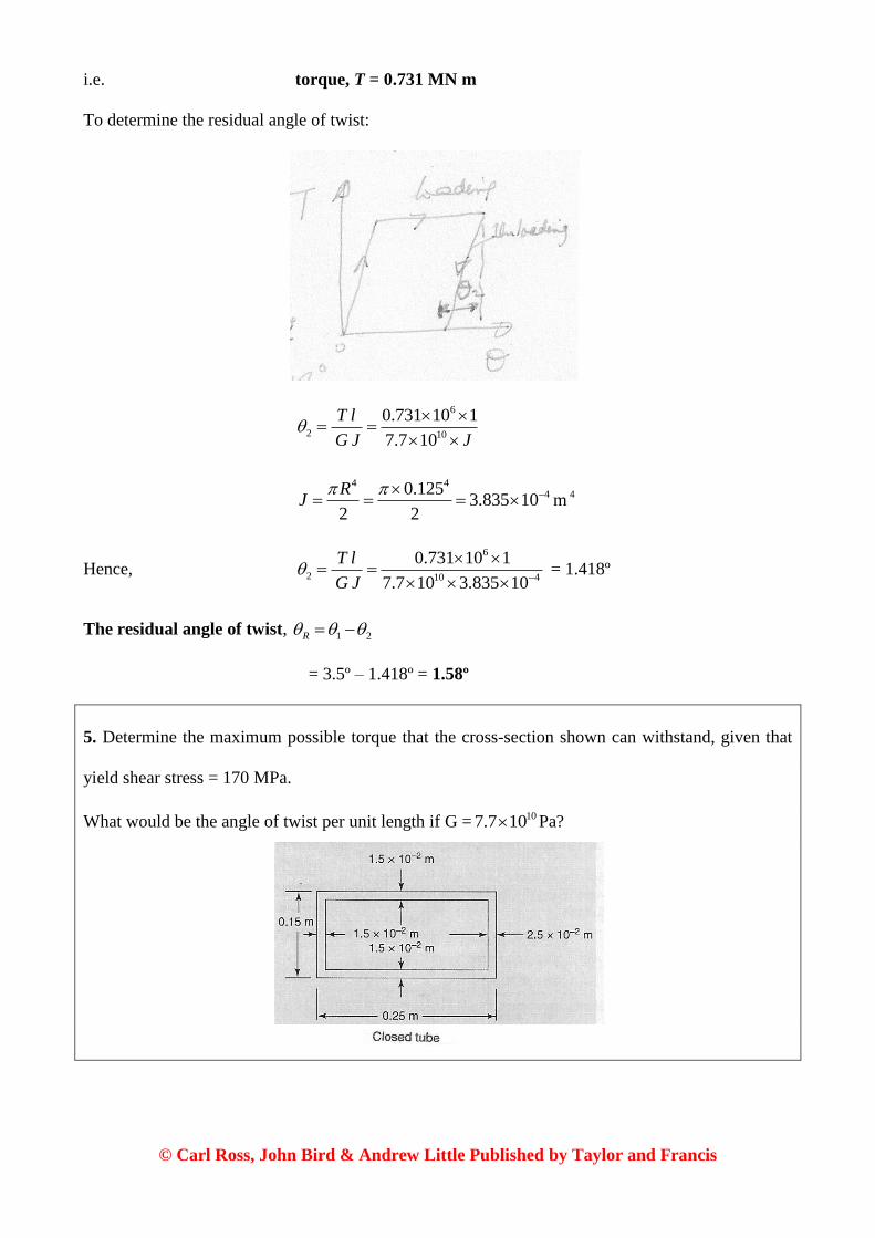
i.e. torque, T = 0.731 MN m
To determine the residual angle of twist:
6
2 10
0.731 10 1
7.7 10
T l
G J J
4 4
40.1253.835 10
2 2
RJ
m4
Hence, 6
2 10 4
0.731 10 1
7.7 10 3.835 10
T l
G J
= 1.418º
The residual angle of twist, 1 2R
= 3.5º – 1.418º = 1.58º
5. Determine the maximum possible torque that the cross-section shown can withstand, given that
yield shear stress = 170 MPa.
What would be the angle of twist per unit length if G = 107.7 10 Pa?

© Carl Ross, John Bird & Andrew Little Published by Taylor and Francis
2
T
At
i.e. 6
2170 10
2 0.15 0.25 1.5 10
T
from which, 6 2170 10 2 0.15 0.25 1.5 10T
i.e. maximum torque, T = 191250 N m = 191.25 kN m
24
T l ds
A G t
= 3 10 2 2
191250 1 180 0.65 0.15
4 1.406 10 7.7 10 1.5 10 2.5 10
= 6
3442500043.33 6
433
i.e. angle of twist, θ = 3.92º/m


![PINCES PARALLÈLES DEUX MORS SÉRIE GPP5000 · 2 days ago · Longueur mors de préhension max. [mm] 245 225 225 225 215 215 Précision de répétition +/- [mm] 0.01 0.01 0.01 0.01](https://img.pdfslide.net/doc/110x75/6101ef34c5a30c31eb404c4b/pinces-parallles-deux-mors-srie-gpp5000-2-days-ago-longueur-mors-de-prhension.jpg)