Embed Size (px)
Citation preview
Chapter 8a: DC Motors 0908531 Mechatronics System Design
© Copyright held by the author 2009: Dr. Lutfi R. Al-Sharif Page 1 of 30
Chapter 8a DC Motors
(Revision 3.0, 15/11/2009) 1. INTRODUCTION It is said that the invention of the AC induction motor was the deciding factor in the 19th Century battle between AC and DC. However, the DC motor has still been with us since then. Good speed-torque characteristics and ease of variable speed control are the main advantages of the using DC motors over AC. With the advent of power electronics (especially the thyristor) in the late sixties, the use of squirrel cage induction in variable speed applications starting emerging. The squirrel cage induction motor is robust and virtually maintenance free as compared to its DC counterpart which uses brushes. Thus there has been a continuous drive to refine the power electronics to attempt to achieve a DC motor performance from an AC squirrel cage induction motor. Although the AC induction motor has virtually replaced the DC motor for small and medium size installations, the DC motor is still used in lifts in high speed gearless applications. In this lesson, we examine the principle of operation of DC motors, and the speed torque characteristics of some of the DC motor types.
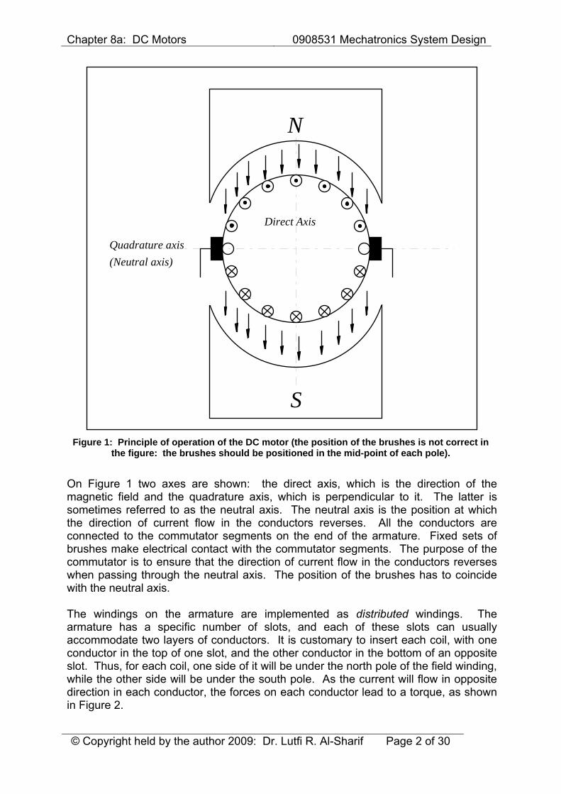
2 PRINCIPLE OF OPERATION The DC motor works on the principle of passing a current in a conductor inside a magnetic field. A force is developed on the conductor. When a group of these conductors are fixed on a rotating armature, a resultant torque is produced from all the forces on the individual conductors. A diagram of this principle is shown in Figure 1. Most power supplies are AC (except for special applications, where the supply is DC, e.g. railways). Thus, in order to operate a DC motor, the AC supply has to be rectified (and possibly controlled) to provide the necessary DC voltage to feed the motor.
Chapter 8a: DC Motors 0908531 Mechatronics System Design
© Copyright held by the author 2009: Dr. Lutfi R. Al-Sharif Page 2 of 30
Quadrature axis
Direct Axis
N
(Neutral axis)
S
Figure 1: Principle of operation of the DC motor (the position of the brushes is not correct in the figure: the brushes should be positioned in the mid-point of each pole).
On Figure 1 two axes are shown: the direct axis, which is the direction of the magnetic field and the quadrature axis, which is perpendicular to it. The latter is sometimes referred to as the neutral axis. The neutral axis is the position at which the direction of current flow in the conductors reverses. All the conductors are connected to the commutator segments on the end of the armature. Fixed sets of brushes make electrical contact with the commutator segments. The purpose of the commutator is to ensure that the direction of current flow in the conductors reverses when passing through the neutral axis. The position of the brushes has to coincide with the neutral axis. The windings on the armature are implemented as distributed windings. The armature has a specific number of slots, and each of these slots can usually accommodate two layers of conductors. It is customary to insert each coil, with one conductor in the top of one slot, and the other conductor in the bottom of an opposite slot. Thus, for each coil, one side of it will be under the north pole of the field winding, while the other side will be under the south pole. As the current will flow in opposite direction in each conductor, the forces on each conductor lead to a torque, as shown in Figure 2.
Chapter 8a: DC Motors 0908531 Mechatronics System Design
© Copyright held by the author 2009: Dr. Lutfi R. Al-Sharif Page 3 of 30
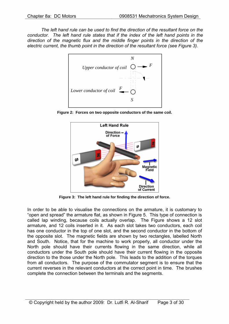
The left hand rule can be used to find the direction of the resultant force on the conductor. The left hand rule states that if the index of the left hand points in the direction of the magnetic flux and the middle finger points in the direction of the electric current, the thumb point in the direction of the resultant force (see Figure 3).
Upper conductor of coil
Lower conductor of coil
N
S
F
F
Figure 2: Forces on two opposite conductors of the same coil.
Figure 3: The left hand rule for finding the direction of force.
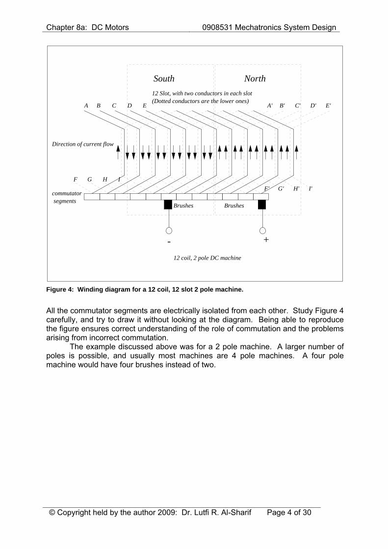
In order to be able to visualise the connections on the armature, it is customary to “open and spread” the armature flat, as shown in Figure 5. This type of connection is called lap winding, because coils actually overlap. The Figure shows a 12 slot armature, and 12 coils inserted in it. As each slot takes two conductors, each coil has one conductor in the top of one slot, and the second conductor in the bottom of the opposite slot. The magnetic fields are shown by two rectangles, labelled North and South. Notice, that for the machine to work properly, all conductor under the North pole should have their currents flowing in the same direction, while all conductors under the South pole should have their current flowing in the opposite direction to the those under the North pole. This leads to the addition of the torques from all conductors. The purpose of the commutator segment is to ensure that the current reverses in the relevant conductors at the correct point in time. The brushes complete the connection between the terminals and the segments.
Chapter 8a: DC Motors 0908531 Mechatronics System Design
© Copyright held by the author 2009: Dr. Lutfi R. Al-Sharif Page 4 of 30
A B C D E A' B' C' D' E'
F G H IF' G' H' I'
+-
12 Slot, with two conductors in each slot(Dotted conductors are the lower ones)
Direction of current flow
NorthSouth
Brushes Brushes
12 coil, 2 pole DC machine
commutatorsegments
Figure 4: Winding diagram for a 12 coil, 12 slot 2 pole machine.
All the commutator segments are electrically isolated from each other. Study Figure 4 carefully, and try to draw it without looking at the diagram. Being able to reproduce the figure ensures correct understanding of the role of commutation and the problems arising from incorrect commutation. The example discussed above was for a 2 pole machine. A larger number of poles is possible, and usually most machines are 4 pole machines. A four pole machine would have four brushes instead of two.
Chapter 8a: DC Motors 0908531 Mechatronics System Design
© Copyright held by the author 2009: Dr. Lutfi R. Al-Sharif Page 5 of 30
M Shunt field
Current limiting resistor
Magnetic field
MotorCurrent
FieldCurrent
250 V DC
+
-
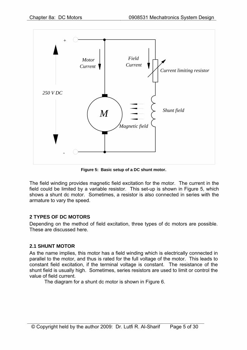
Figure 5: Basic setup of a DC shunt motor.
The field winding provides magnetic field excitation for the motor. The current in the field could be limited by a variable resistor. This set-up is shown in Figure 5, which shows a shunt dc motor. Sometimes, a resistor is also connected in series with the armature to vary the speed.
2 TYPES OF DC MOTORS Depending on the method of field excitation, three types of dc motors are possible. These are discussed here.
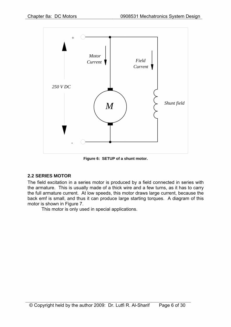
2.1 SHUNT MOTOR As the name implies, this motor has a field winding which is electrically connected in parallel to the motor, and thus is rated for the full voltage of the motor. This leads to constant field excitation, if the terminal voltage is constant. The resistance of the shunt field is usually high. Sometimes, series resistors are used to limit or control the value of field current. The diagram for a shunt dc motor is shown in Figure 6.
Chapter 8a: DC Motors 0908531 Mechatronics System Design
© Copyright held by the author 2009: Dr. Lutfi R. Al-Sharif Page 6 of 30
M Shunt field
MotorCurrent
250 V DC
+
-
FieldCurrent
Figure 6: SETUP of a shunt motor.
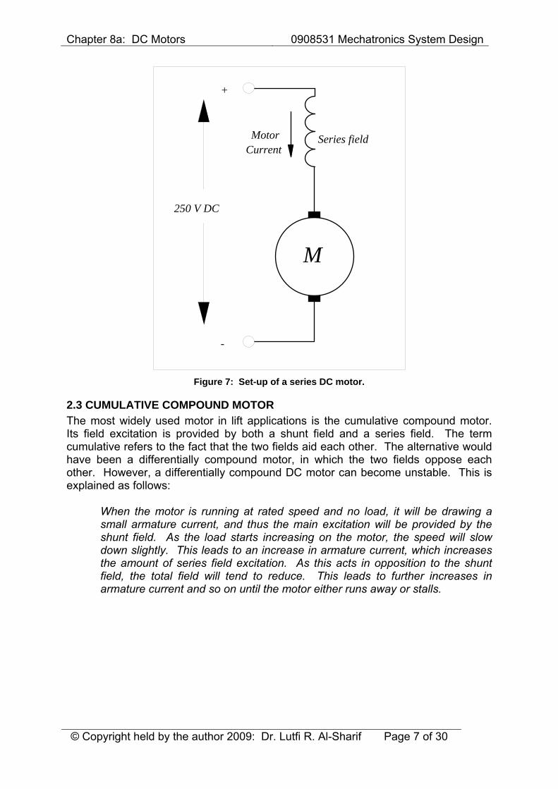
2.2 SERIES MOTOR The field excitation in a series motor is produced by a field connected in series with the armature. This is usually made of a thick wire and a few turns, as it has to carry the full armature current. At low speeds, this motor draws large current, because the back emf is small, and thus it can produce large starting torques. A diagram of this motor is shown in Figure 7. This motor is only used in special applications.
Chapter 8a: DC Motors 0908531 Mechatronics System Design
© Copyright held by the author 2009: Dr. Lutfi R. Al-Sharif Page 7 of 30
M
MotorCurrent
250 V DC
+
-
Series field
Figure 7: Set-up of a series DC motor.
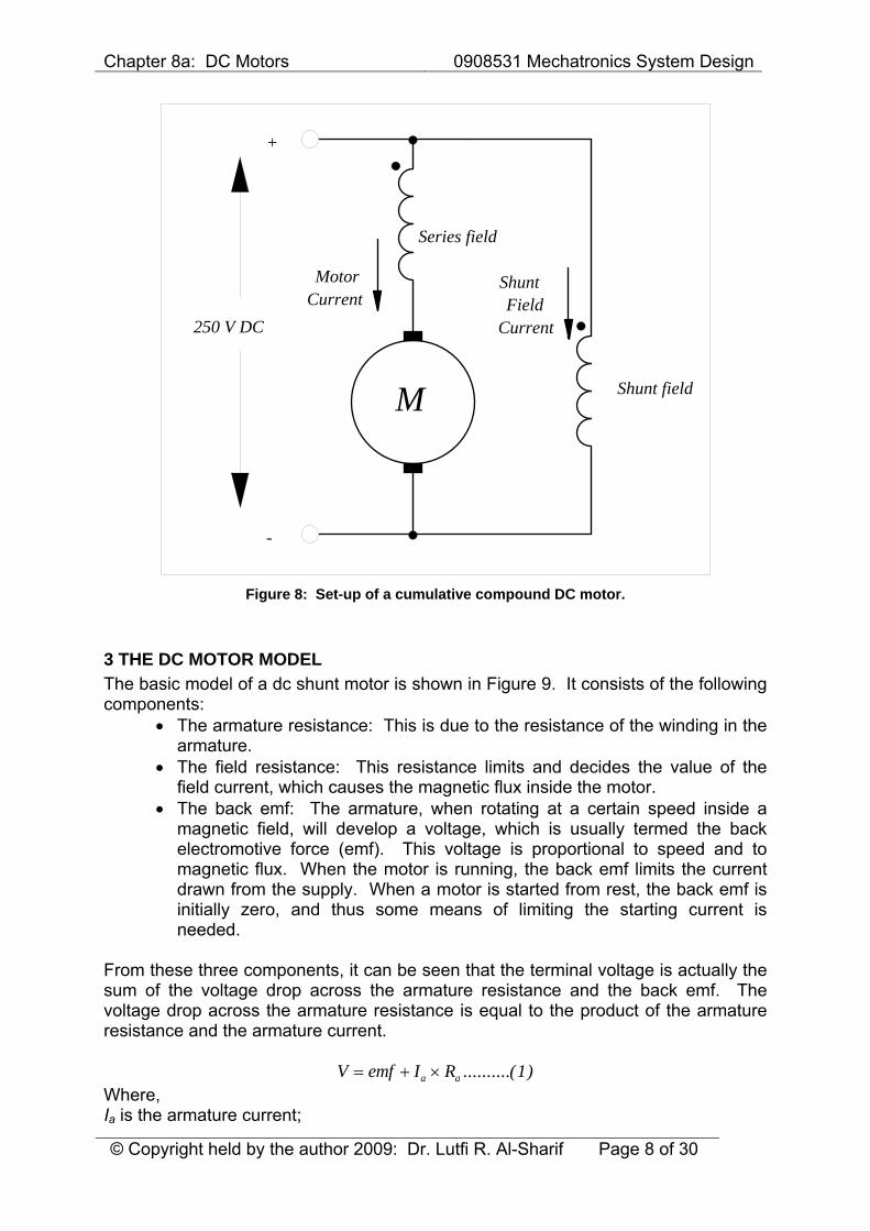
2.3 CUMULATIVE COMPOUND MOTOR The most widely used motor in lift applications is the cumulative compound motor. Its field excitation is provided by both a shunt field and a series field. The term cumulative refers to the fact that the two fields aid each other. The alternative would have been a differentially compound motor, in which the two fields oppose each other. However, a differentially compound DC motor can become unstable. This is explained as follows:
When the motor is running at rated speed and no load, it will be drawing a small armature current, and thus the main excitation will be provided by the shunt field. As the load starts increasing on the motor, the speed will slow down slightly. This leads to an increase in armature current, which increases the amount of series field excitation. As this acts in opposition to the shunt field, the total field will tend to reduce. This leads to further increases in armature current and so on until the motor either runs away or stalls.
Chapter 8a: DC Motors 0908531 Mechatronics System Design
© Copyright held by the author 2009: Dr. Lutfi R. Al-Sharif Page 8 of 30
M Shunt field
MotorCurrent
250 V DC
+
-
FieldCurrent
Series field
Shunt
Figure 8: Set-up of a cumulative compound DC motor.
3 THE DC MOTOR MODEL The basic model of a dc shunt motor is shown in Figure 9. It consists of the following components:
• The armature resistance: This is due to the resistance of the winding in the armature.
• The field resistance: This resistance limits and decides the value of the field current, which causes the magnetic flux inside the motor.
• The back emf: The armature, when rotating at a certain speed inside a magnetic field, will develop a voltage, which is usually termed the back electromotive force (emf). This voltage is proportional to speed and to magnetic flux. When the motor is running, the back emf limits the current drawn from the supply. When a motor is started from rest, the back emf is initially zero, and thus some means of limiting the starting current is needed.
From these three components, it can be seen that the terminal voltage is actually the sum of the voltage drop across the armature resistance and the back emf. The voltage drop across the armature resistance is equal to the product of the armature resistance and the armature current.
V emf I Ra a= + × ..........( )1 Where, Ia is the armature current;

Chapter 8a: DC Motors 0908531 Mechatronics System Design
© Copyright held by the author 2009: Dr. Lutfi R. Al-Sharif Page 9 of 30
Ra is the armature resistance; emf is the back emf generated by the armature (sometimes called back emf). [N.B.: In the following discussion, constants denoted by K will be introduced. The numbering of these constants is arbitrary, and they are used in the derivation for mathematical convenience, and do not necessarily has a direct physical significance.] The back emf, as mentioned earlier, is proportional to the speed and the magnetic flux.
emf K n= × ×1 2Φ ..........( ) Where, K1 is a constant; Φ is the magnetic flux; n is the speed. Thus, the final equation which describes the operation of the motor, is:
V K n I Ra a= +1 3Φ ..........( )
EMF Shunt field
+
-
VIa
Ra
(KNI )f
+
-
If
Rf
+
-
Figure 9: Model of a shunt DC motor.
Chapter 8a: DC Motors 0908531 Mechatronics System Design
© Copyright held by the author 2009: Dr. Lutfi R. Al-Sharif Page 10 of 30
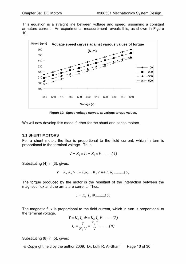
This equation is a straight line between voltage and speed, assuming a constant armature current. An experimental measurement reveals this, as shown in Figure 10.
Votlage speed curves against various values of torque
(N.m)
490
500
510
520
530
540
550
560
550 560 570 580 590 600 610 620 630 640 650
Voltage (V)
Speed (rpm)
100200300500
Figure 10: Speed voltage curves, at various torque values.
We will now develop this model further for the shunt and series motors.
3.1 SHUNT MOTORS For a shunt motor, the flux is proportional to the field current, which in turn is proportional to the terminal voltage. Thus,
Φ = × = ×K I K Vf2 3 4..........( ) Substituting (4) in (3), gives:
V K K V n I R K V n I Ra a a a= + = +1 3 4 5..........( ) The torque produced by the motor is the resultant of the interaction between the magnetic flux and the armature current. Thus,
T K Ia= 5 6Φ ..........( )
The magnetic flux is proportional to the field current, which in turn is proportional to the terminal voltage.
T K I K I Va a= =5 6 7Φ ..........( )
I TK V
K TVa = =
6
7 8..........( )
Substituting (8) in (5), gives:
Chapter 8a: DC Motors 0908531 Mechatronics System Design
© Copyright held by the author 2009: Dr. Lutfi R. Al-Sharif Page 11 of 30
V K V n I R K V n K T RVa a
a= + = +4 47 9..........( )
Re-arranging, gives:
K V n V K T RV
K V n V K T R
n V K T RK V
K K T RV
K K RV
T
a
a
a a a
47
42 2
7
27
42 8
92 8
92
9
10
11
= −
= −
=−
= − = − ⎛⎝⎜
⎞⎠⎟
..........( )
..........( )
..........( )
Or:
TV K V n
K Ra
=−2
42
7
12..........( )
Thus, the speed torque characteristic is a negative sloping line, the slope of which changes with the square of the voltage.
3.2 SERIES MOTOR For a series motor, the flux is proportional to the armature current. Thus,
Φ = ×K Ia10 13..........( ) Substituting (4) in (3), gives:
V K K I n I R K I n I Ra a a a a a= + = +1 10 11 14..........( ) The torque produced by the motor is the resultant of the interaction between the magnetic flux and the armature current. Thus,
T K Ia= 5 15Φ ..........( )
But the magnetic flux is proportional to the armature current, which gives:
T K I K I K Ia a a= =5 10 122 16..........( )
I TK
K Ta = =12
13 17..........( )
Substituting (16) in (13), gives:
( ) ( )V K I n I R I K n R K T K n Ra a a a a a= + = + = +11 11 13 11 18..........( ) Re-arranging, gives:
Chapter 8a: DC Motors 0908531 Mechatronics System Design
© Copyright held by the author 2009: Dr. Lutfi R. Al-Sharif Page 12 of 30
( )T V
K n R Ka
=+
⎛
⎝⎜
⎞
⎠⎟
11 13
2
19..........( )
Thus, the torque for a series motor is proportional to the square of the inverse of the speed. This leads to a hyperbolic speed-torque curve.
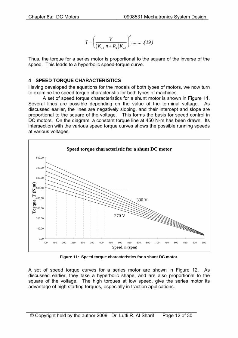
4 SPEED TORQUE CHARACTERISTICS Having developed the equations for the models of both types of motors, we now turn to examine the speed torque characteristic for both types of machines. A set of speed torque characteristics for a shunt motor is shown in Figure 11. Several lines are possible depending on the value of the terminal voltage. As discussed earlier, the lines are negatively sloping, and their intercept and slope are proportional to the square of the voltage. This forms the basis for speed control in DC motors. On the diagram, a constant torque line at 450 N·m has been drawn. Its intersection with the various speed torque curves shows the possible running speeds at various voltages.
Speed torque characteristic for a shunt DC motor
0.00
100.00
200.00
300.00
400.00
500.00
600.00
700.00
800.00
100 150 200 250 300 350 400 450 500 550 600 650 700 750 800 850 900 950
Speed, n (rpm)
Tor
que,
T (N
.m)
330 V
270 V
Figure 11: Speed torque characteristics for a shunt DC motor.
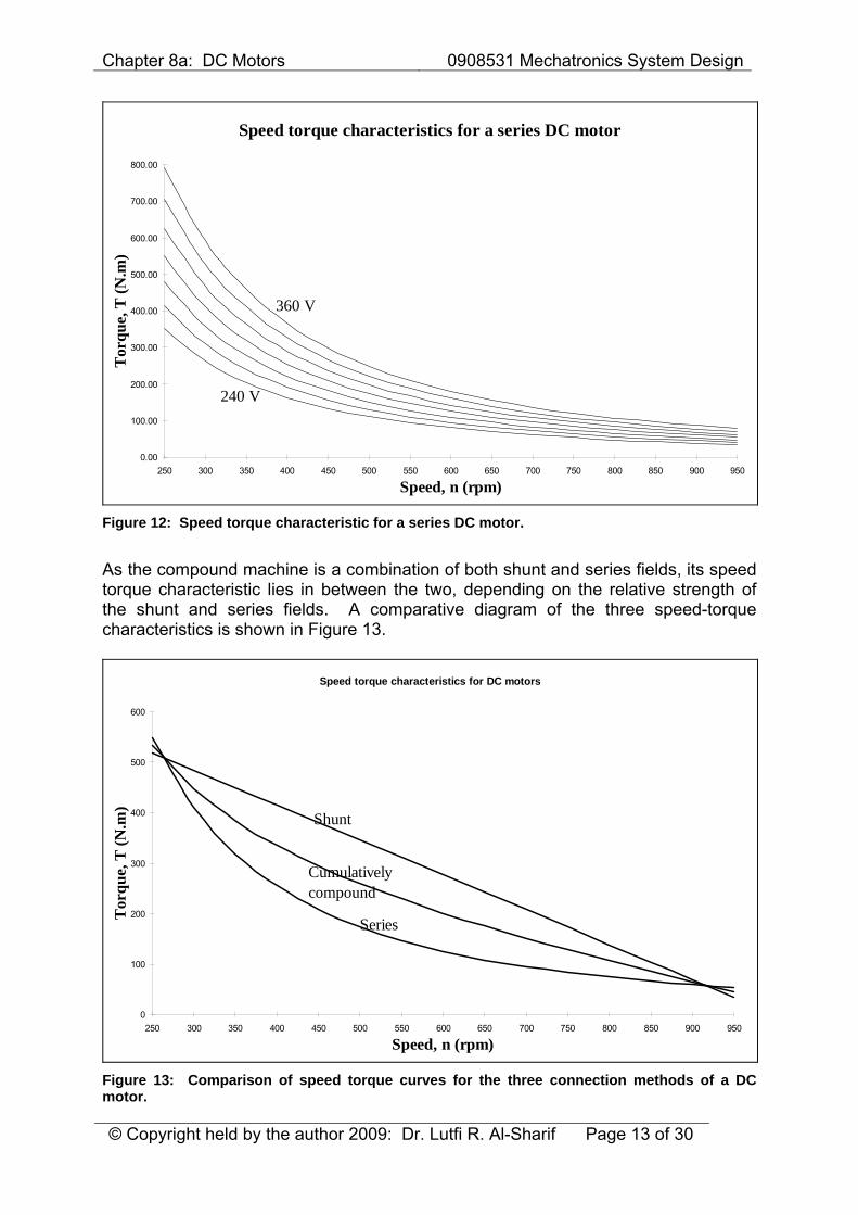
A set of speed torque curves for a series motor are shown in Figure 12. As discussed earlier, they take a hyperbolic shape, and are also proportional to the square of the voltage. The high torques at low speed, give the series motor its advantage of high starting torques, especially in traction applications.
Chapter 8a: DC Motors 0908531 Mechatronics System Design
© Copyright held by the author 2009: Dr. Lutfi R. Al-Sharif Page 13 of 30
Speed torque characteristics for a series DC motor
0.00
100.00
200.00
300.00
400.00
500.00
600.00
700.00
800.00
250 300 350 400 450 500 550 600 650 700 750 800 850 900 950
Speed, n (rpm)
Tor
que,
T (N
.m)
360 V
240 V
Figure 12: Speed torque characteristic for a series DC motor.
As the compound machine is a combination of both shunt and series fields, its speed torque characteristic lies in between the two, depending on the relative strength of the shunt and series fields. A comparative diagram of the three speed-torque characteristics is shown in Figure 13.
Speed torque characteristics for DC motors
0
100
200
300
400
500
600
250 300 350 400 450 500 550 600 650 700 750 800 850 900 950
Speed, n (rpm)
Tor
que,
T (N
.m)
Shunt
Series
Cumulatively compound
Figure 13: Comparison of speed torque curves for the three connection methods of a DC motor.
Chapter 8a: DC Motors 0908531 Mechatronics System Design
© Copyright held by the author 2009: Dr. Lutfi R. Al-Sharif Page 14 of 30
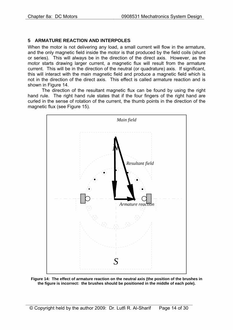
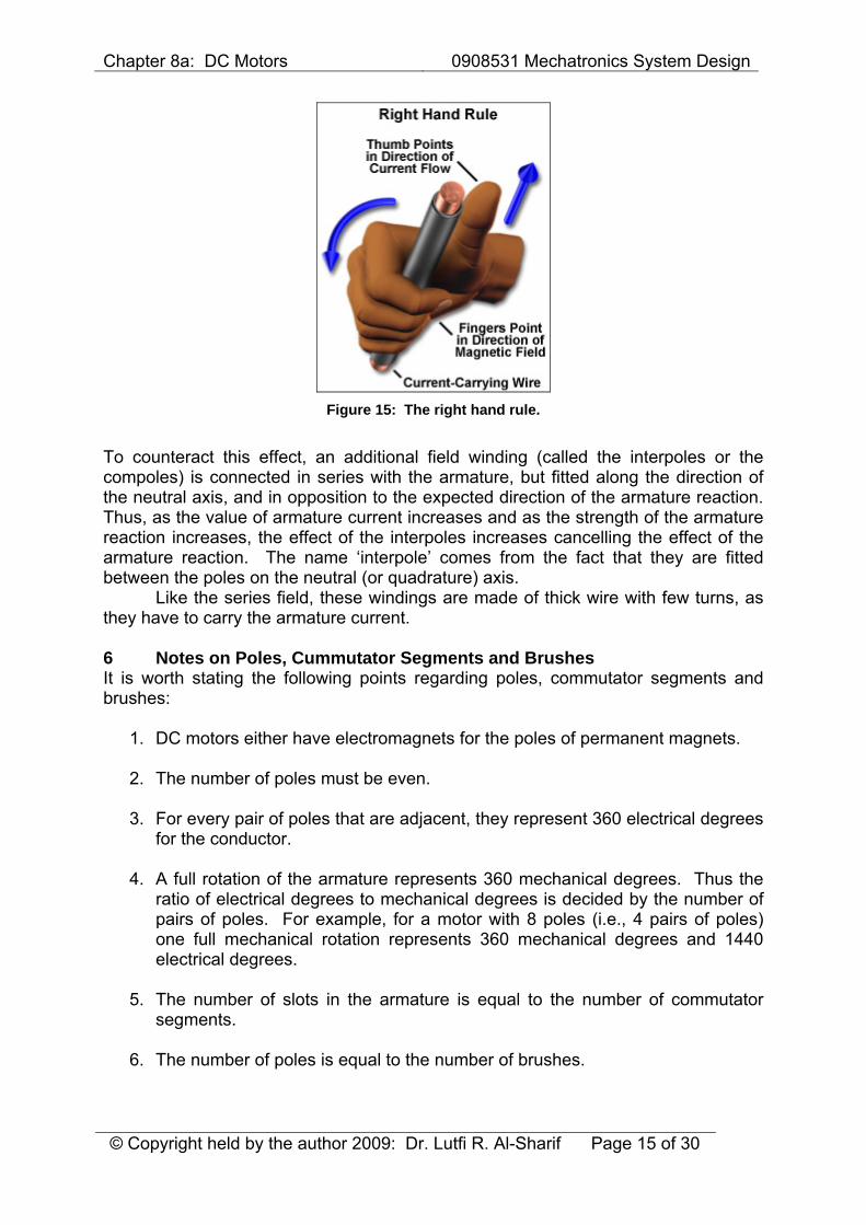
5 ARMATURE REACTION AND INTERPOLES When the motor is not delivering any load, a small current will flow in the armature, and the only magnetic field inside the motor is that produced by the field coils (shunt or series). This will always be in the direction of the direct axis. However, as the motor starts drawing larger current, a magnetic flux will result from the armature current. This will be in the direction of the neutral (or quadrature) axis. If significant, this will interact with the main magnetic field and produce a magnetic field which is not in the direction of the direct axis. This effect is called armature reaction and is shown in Figure 14. The direction of the resultant magnetic flux can be found by using the right hand rule. The right hand rule states that if the four fingers of the right hand are curled in the sense of rotation of the current, the thumb points in the direction of the magnetic flux (see Figure 15).
N
S
Main field
Armature reaction
Resultant field
Figure 14: The effect of armature reaction on the neutral axis (the position of the brushes in
the figure is incorrect: the brushes should be positioned in the middle of each pole).
Chapter 8a: DC Motors 0908531 Mechatronics System Design
© Copyright held by the author 2009: Dr. Lutfi R. Al-Sharif Page 15 of 30
Figure 15: The right hand rule.
To counteract this effect, an additional field winding (called the interpoles or the compoles) is connected in series with the armature, but fitted along the direction of the neutral axis, and in opposition to the expected direction of the armature reaction. Thus, as the value of armature current increases and as the strength of the armature reaction increases, the effect of the interpoles increases cancelling the effect of the armature reaction. The name ‘interpole’ comes from the fact that they are fitted between the poles on the neutral (or quadrature) axis. Like the series field, these windings are made of thick wire with few turns, as they have to carry the armature current. 6 Notes on Poles, Cummutator Segments and Brushes It is worth stating the following points regarding poles, commutator segments and brushes:
1. DC motors either have electromagnets for the poles of permanent magnets.
2. The number of poles must be even.
3. For every pair of poles that are adjacent, they represent 360 electrical degrees for the conductor.
4. A full rotation of the armature represents 360 mechanical degrees. Thus the ratio of electrical degrees to mechanical degrees is decided by the number of pairs of poles. For example, for a motor with 8 poles (i.e., 4 pairs of poles) one full mechanical rotation represents 360 mechanical degrees and 1440 electrical degrees.
5. The number of slots in the armature is equal to the number of commutator segments.
6. The number of poles is equal to the number of brushes.
Chapter 8a: DC Motors 0908531 Mechatronics System Design
© Copyright held by the author 2009: Dr. Lutfi R. Al-Sharif Page 16 of 30
7. All the brushes are fitted on one ring. The angular position of the ring can usually be adjusted.
8. The brushes are usually fitted with spring loaded graphite pieces. As graphite is softer that the commutator segment material, the brushes will wear over time and need replacing.
7 PHOTOGRAPHS FROM ACTUAL DC MOTORS The following photographs have been taken from actual dc motors in order to illustrate the concepts introduced earlier.
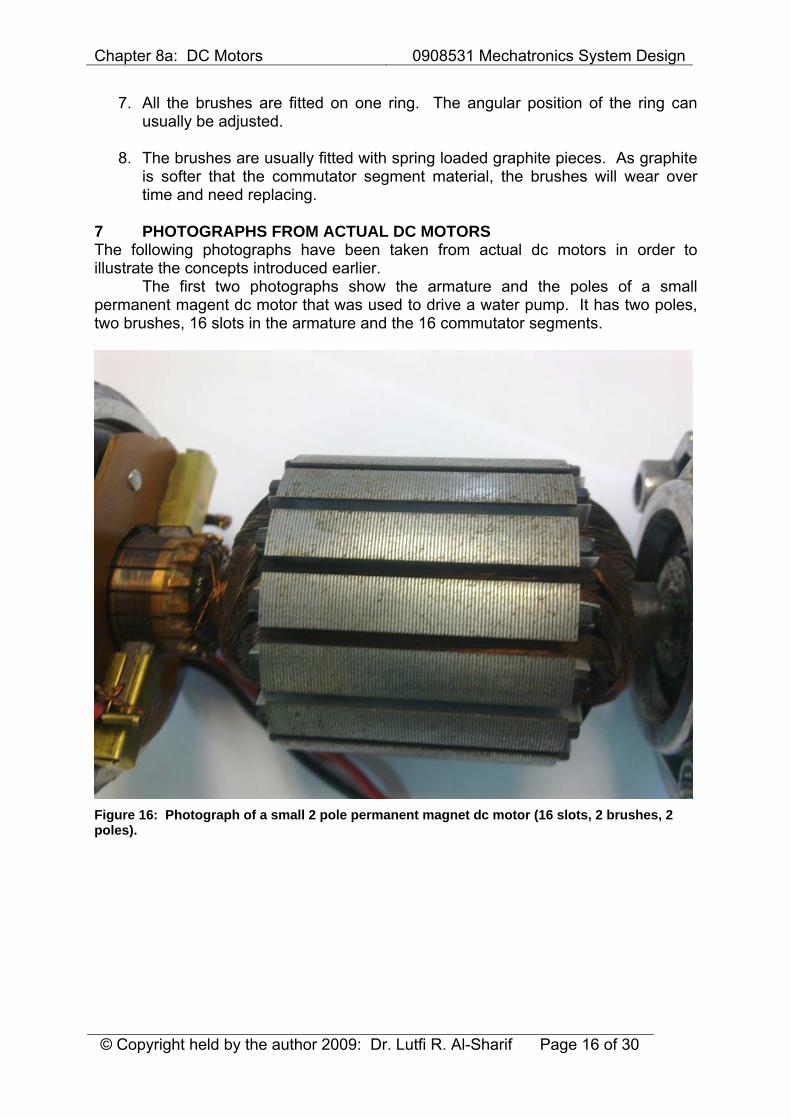
The first two photographs show the armature and the poles of a small permanent magent dc motor that was used to drive a water pump. It has two poles, two brushes, 16 slots in the armature and the 16 commutator segments.
Figure 16: Photograph of a small 2 pole permanent magnet dc motor (16 slots, 2 brushes, 2 poles).
Chapter 8a: DC Motors 0908531 Mechatronics System Design
© Copyright held by the author 2009: Dr. Lutfi R. Al-Sharif Page 17 of 30
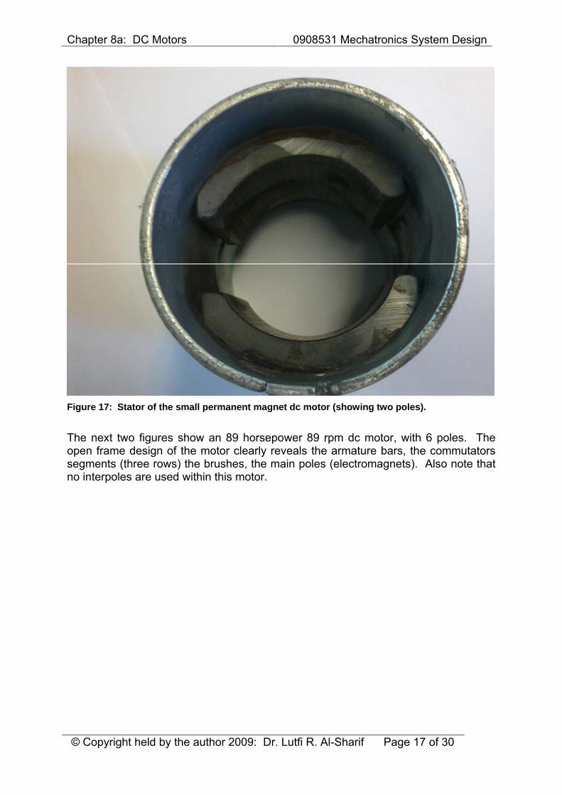
Figure 17: Stator of the small permanent magnet dc motor (showing two poles).
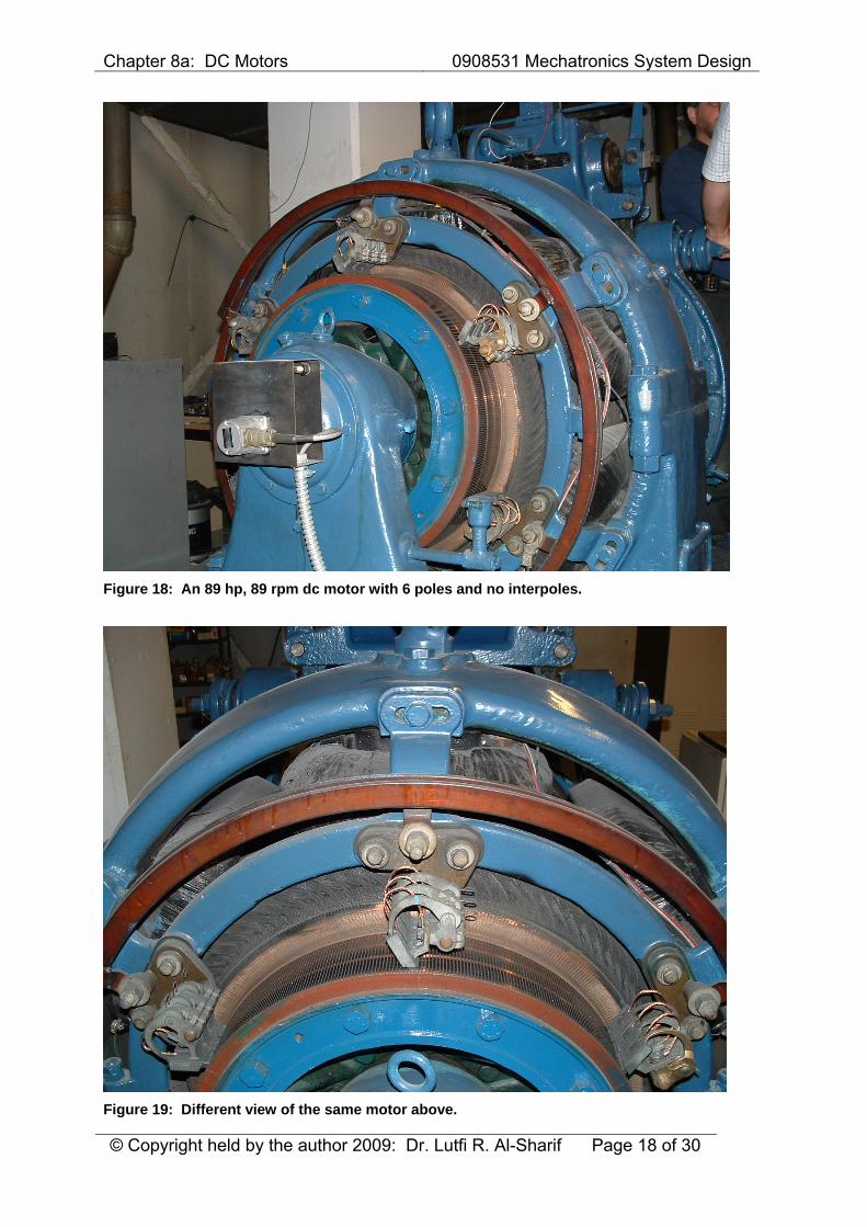
The next two figures show an 89 horsepower 89 rpm dc motor, with 6 poles. The open frame design of the motor clearly reveals the armature bars, the commutators segments (three rows) the brushes, the main poles (electromagnets). Also note that no interpoles are used within this motor.
Chapter 8a: DC Motors 0908531 Mechatronics System Design
© Copyright held by the author 2009: Dr. Lutfi R. Al-Sharif Page 18 of 30
Figure 18: An 89 hp, 89 rpm dc motor with 6 poles and no interpoles.
Figure 19: Different view of the same motor above.
Chapter 8a: DC Motors 0908531 Mechatronics System Design
© Copyright held by the author 2009: Dr. Lutfi R. Al-Sharif Page 19 of 30
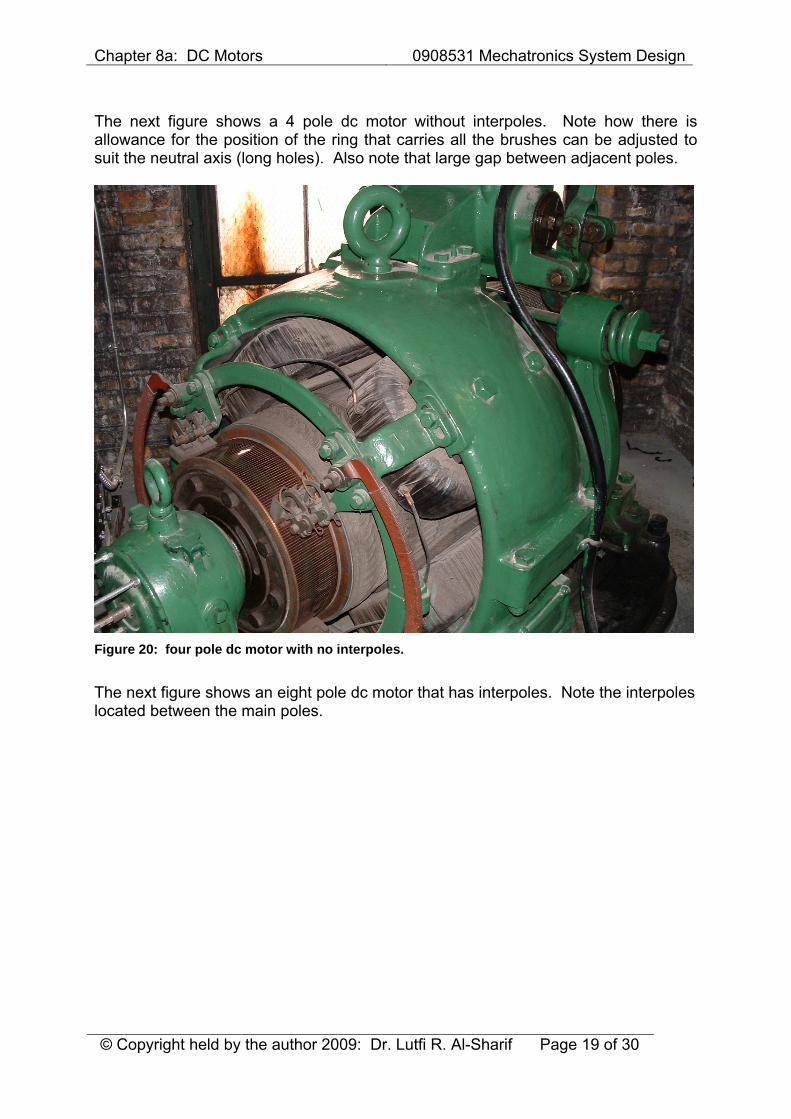
The next figure shows a 4 pole dc motor without interpoles. Note how there is allowance for the position of the ring that carries all the brushes can be adjusted to suit the neutral axis (long holes). Also note that large gap between adjacent poles.
Figure 20: four pole dc motor with no interpoles.
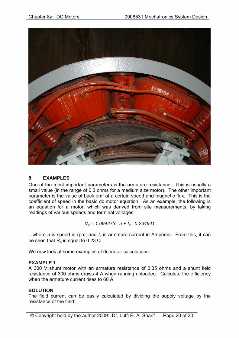
The next figure shows an eight pole dc motor that has interpoles. Note the interpoles located between the main poles.
Chapter 8a: DC Motors 0908531 Mechatronics System Design
© Copyright held by the author 2009: Dr. Lutfi R. Al-Sharif Page 20 of 30
8 EXAMPLES One of the most important parameters is the armature resistance. This is usually a small value (in the range of 0.3 ohms for a medium size motor). The other important parameter is the value of back emf at a certain speed and magnetic flux. This is the coefficient of speed in the basic dc motor equation. As an example, the following is an equation for a motor, which was derived from site measurements, by taking readings of various speeds and terminal voltages.
Va = 1.094273 . n + Ia . 0.234941 ...where n is speed in rpm, and Ia is armature current in Amperes. From this, it can be seen that Ra is equal to 0.23 Ω. We now look at some examples of dc motor calculations. EXAMPLE 1 A 300 V shunt motor with an armature resistance of 0.35 ohms and a shunt field resistance of 300 ohms draws 4 A when running unloaded. Calculate the efficiency when the armature current rises to 60 A. SOLUTION The field current can be easily calculated by dividing the supply voltage by the resistance of the field:
Chapter 8a: DC Motors 0908531 Mechatronics System Design
© Copyright held by the author 2009: Dr. Lutfi R. Al-Sharif Page 21 of 30
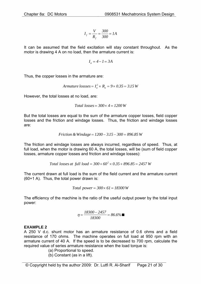
I VR
Aff
= = =300300
1
It can be assumed that the field excitation will stay constant throughout. As the motor is drawing 4 A on no load, then the armature current is:
I Aa = − =4 1 3 Thus, the copper losses in the armature are:
Armature lossses I R Wa a= × = × =2 9 0 35 3 15. . However, the total losses at no load, are:
Total losses W= × =300 4 1200 But the total losses are equal to the sum of the armature copper losses, field copper losses and the friction and windage losses. Thus, the friction and windage losses are:
Friction Windage W& . .= − − =1200 3 15 300 896 85 The friction and windage losses are always incurred, regardless of speed. Thus, at full load, when the motor is drawing 60 A, the total losses, will be (sum of field copper losses, armature copper losses and friction and windage losses):
Total losses at full load W= + × + =300 60 0 35 896 85 24572 . . The current drawn at full load is the sum of the field current and the armature current (60+1 A). Thus, the total power drawn is:
Total power W= × =300 61 18300 The efficiency of the machine is the ratio of the useful output power by the total input power:
η =−
=18300 2457
1830086 6%.
EXAMPLE 2 A 250 V d.c. shunt motor has an armature resistance of 0.6 ohms and a field resistance of 170 ohms. The machine operates on full load at 950 rpm with an armature current of 40 A. If the speed is to be decreased to 700 rpm, calculate the required value of series armature resistance when the load torque is:
(a) Proportional to speed. (b) Constant (as in a lift).
Chapter 8a: DC Motors 0908531 Mechatronics System Design
© Copyright held by the author 2009: Dr. Lutfi R. Al-Sharif Page 22 of 30
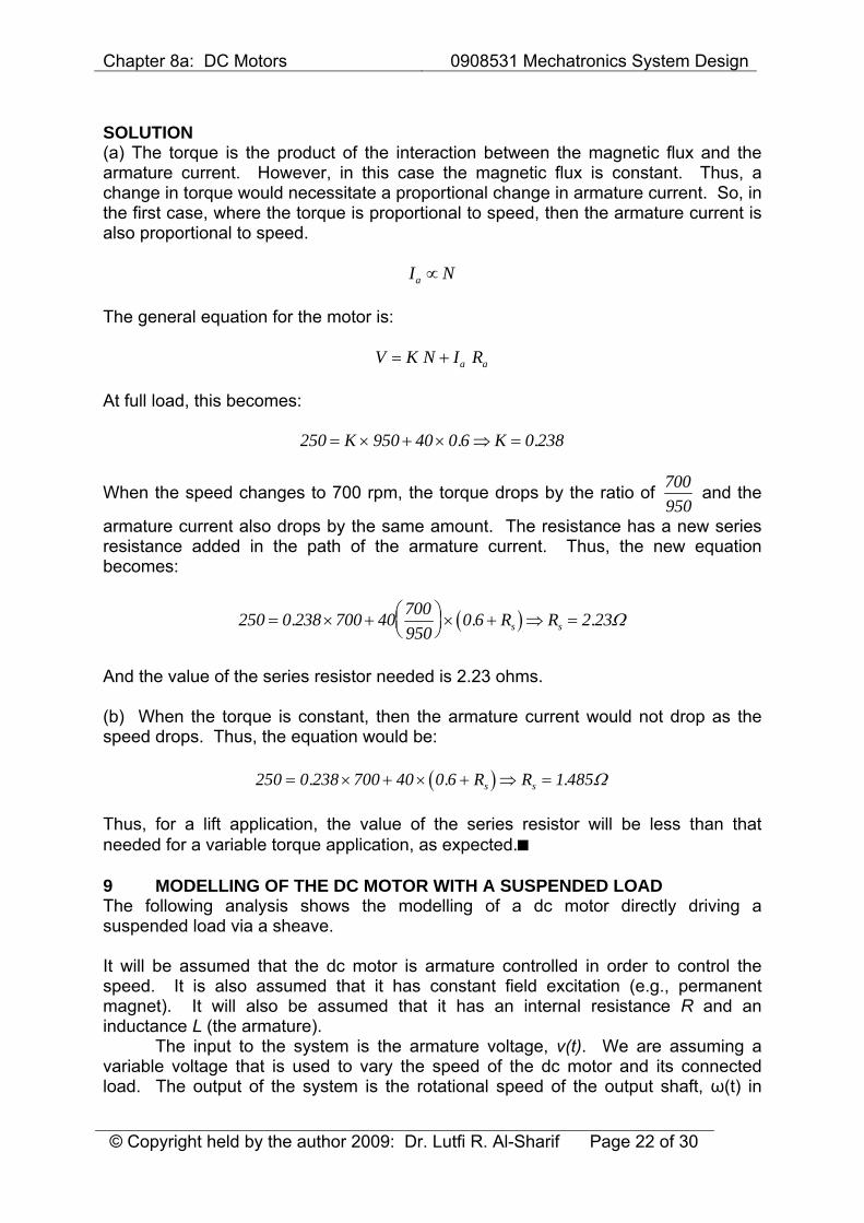
SOLUTION (a) The torque is the product of the interaction between the magnetic flux and the armature current. However, in this case the magnetic flux is constant. Thus, a change in torque would necessitate a proportional change in armature current. So, in the first case, where the torque is proportional to speed, then the armature current is also proportional to speed.
I Na ∝ The general equation for the motor is:
V K N I Ra a= + At full load, this becomes:
250 950 40 0 6 0 238= × + × ⇒ =K K. .
When the speed changes to 700 rpm, the torque drops by the ratio of 700950
and the
armature current also drops by the same amount. The resistance has a new series resistance added in the path of the armature current. Thus, the new equation becomes:
( )250 0 238 700 40 700950
0 6 2 23= × + ⎛⎝⎜
⎞⎠⎟× + ⇒ =. . .R Rs s Ω
And the value of the series resistor needed is 2.23 ohms. (b) When the torque is constant, then the armature current would not drop as the speed drops. Thus, the equation would be:
( )250 0 238 700 40 0 6 1 485= × + × + ⇒ =. . .R Rs s Ω Thus, for a lift application, the value of the series resistor will be less than that needed for a variable torque application, as expected. 9 MODELLING OF THE DC MOTOR WITH A SUSPENDED LOAD The following analysis shows the modelling of a dc motor directly driving a suspended load via a sheave. It will be assumed that the dc motor is armature controlled in order to control the speed. It is also assumed that it has constant field excitation (e.g., permanent magnet). It will also be assumed that it has an internal resistance R and an inductance L (the armature). The input to the system is the armature voltage, v(t). We are assuming a variable voltage that is used to vary the speed of the dc motor and its connected load. The output of the system is the rotational speed of the output shaft, ω(t) in
Chapter 8a: DC Motors 0908531 Mechatronics System Design
© Copyright held by the author 2009: Dr. Lutfi R. Al-Sharif Page 23 of 30
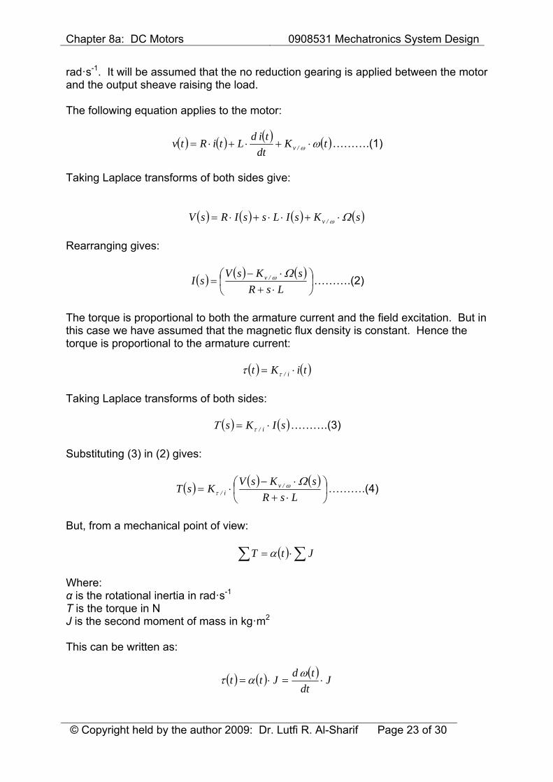
rad·s-1. It will be assumed that the no reduction gearing is applied between the motor and the output sheave raising the load. The following equation applies to the motor:
( ) ( ) ( ) ( )tKdt
tidLtiRtv /v ωω ⋅+⋅+⋅= ……….(1)
Taking Laplace transforms of both sides give:
( ) ( ) ( ) ( )sKsILssIRsV /v Ωω ⋅+⋅⋅+⋅= Rearranging gives:
( ) ( ) ( )⎟⎠⎞
⎜⎝⎛
⋅+⋅−
=LsR
sKsVsI /v Ωω ……….(2)
The torque is proportional to both the armature current and the field excitation. But in this case we have assumed that the magnetic flux density is constant. Hence the torque is proportional to the armature current:
( ) ( )tiKt i/ ⋅= ττ
Taking Laplace transforms of both sides:
( ) ( )sIKs i/ ⋅= τΤ ……….(3)
Substituting (3) in (2) gives:
( ) ( ) ( )⎟⎠⎞
⎜⎝⎛
⋅+⋅−
⋅=LsR
sKsVKsT /v
i/Ωω
τ ……….(4)
But, from a mechanical point of view:
( ) ∑∑ ⋅= JtT α Where: α is the rotational inertia in rad·s-1 T is the torque in N J is the second moment of mass in kg·m2 This can be written as:
( ) ( ) ( ) Jdt
tdJtt ⋅=⋅=ωατ
Chapter 8a: DC Motors 0908531 Mechatronics System Design
© Copyright held by the author 2009: Dr. Lutfi R. Al-Sharif Page 24 of 30
Taking Laplace transforms gives:
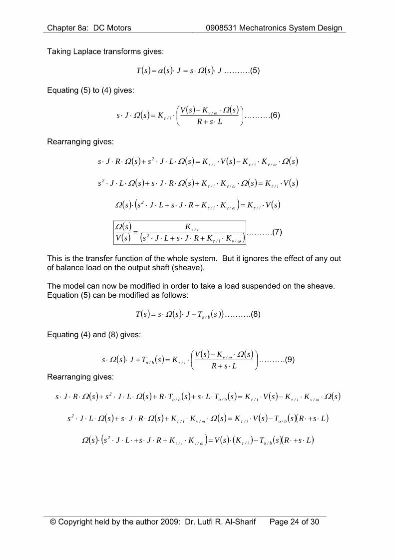
( ) ( ) ( ) JssJssT ⋅⋅=⋅= Ωα ……….(5)
Equating (5) to (4) gives:
( ) ( ) ( )⎟⎠⎞
⎜⎝⎛
⋅+⋅−
⋅=⋅⋅LsR
sKsVKsJs /v
i/Ω
Ω ωτ ……….(6)
Rearranging gives:
( ) ( ) ( ) ( )sKKsVKsLJssRJs /vi/i/2 ΩΩΩ ωττ ⋅⋅−⋅=⋅⋅⋅+⋅⋅⋅
( ) ( ) ( ) ( )sVKsKKsRJssLJs i//vi/
2 ⋅=⋅⋅+⋅⋅⋅+⋅⋅⋅ τωτ ΩΩΩ
( ) ( ) ( )sVKKKRJsLJss i//vi/2 ⋅=⋅+⋅⋅+⋅⋅⋅ τωτΩ
( )( ) ( )ωτ
τΩ
/vi/2
i/
KKRJsLJsK
sVs
⋅+⋅⋅+⋅⋅= ……….(7)
This is the transfer function of the whole system. But it ignores the effect of any out of balance load on the output shaft (sheave). The model can now be modified in order to take a load suspended on the sheave. Equation (5) can be modified as follows:
( ) ( ) ( ))sTJsssT b/o+⋅⋅= Ω ……….(8) Equating (4) and (8) gives:
( ) ( ) ( ) ( )⎟⎠⎞
⎜⎝⎛
⋅+⋅−
⋅=+⋅⋅LsR
sKsVKsTJss /v
i/b/oΩ
Ω ωτ ……….(9)
Rearranging gives:
( ) ( ) ( ) ( ) ( ) ( )sKKsVKsTLssTRsLJssRJs /vi/i/b/ob/o2 ΩΩΩ ωττ ⋅⋅−⋅=⋅⋅+⋅+⋅⋅⋅+⋅⋅⋅
( ) ( ) ( ) ( ) ( )( )LsRsTsVKsKKsRJssLJs b/oi//vi/
2 ⋅+⋅−⋅=⋅⋅+⋅⋅⋅+⋅⋅⋅ τωτ ΩΩΩ
( ) ( ) ( ) ( ) ( )( )LsRsTKsVKKRJsLJss b/oi//vi/2 ⋅+⋅−⋅=⋅+⋅⋅+⋅⋅⋅⋅ τωτΩ
Chapter 8a: DC Motors 0908531 Mechatronics System Design
© Copyright held by the author 2009: Dr. Lutfi R. Al-Sharif Page 25 of 30
( )
( ) ( )( )
( ) ( )( )⎟⎟⎠
⎞⎜⎜⎝
⎛⋅+⋅⋅+⋅⋅⋅
⋅+⋅⋅−
⎟⎟⎠
⎞⎜⎜⎝
⎛⋅+⋅⋅+⋅⋅⋅
⋅
=
ωτ
ωτ
τ
Ω
/vi/2b/o
/vi/2
i/
KKRJsLJsLsRsT
KKRJsLJsK
sV
s
……….(10)
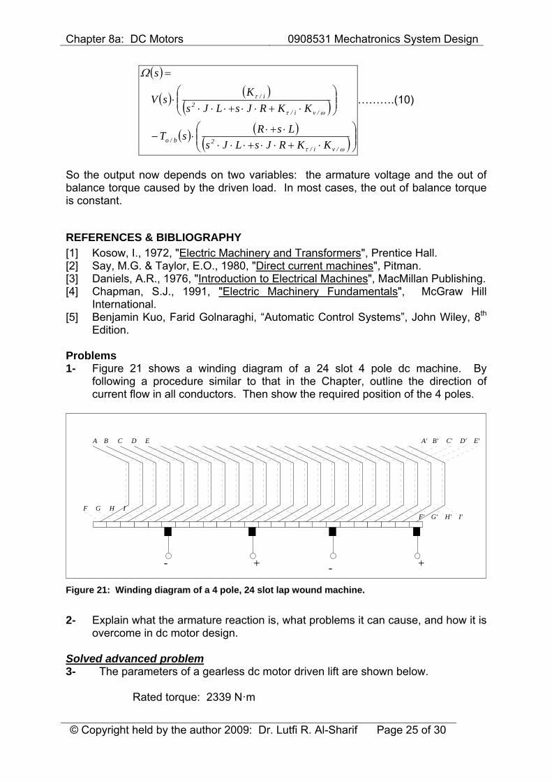
So the output now depends on two variables: the armature voltage and the out of balance torque caused by the driven load. In most cases, the out of balance torque is constant.
REFERENCES & BIBLIOGRAPHY [1] Kosow, I., 1972, "Electric Machinery and Transformers", Prentice Hall. [2] Say, M.G. & Taylor, E.O., 1980, "Direct current machines", Pitman. [3] Daniels, A.R., 1976, "Introduction to Electrical Machines", MacMillan Publishing. [4] Chapman, S.J., 1991, "Electric Machinery Fundamentals", McGraw Hill
International. [5] Benjamin Kuo, Farid Golnaraghi, “Automatic Control Systems”, John Wiley, 8th
Edition. Problems 1- Figure 21 shows a winding diagram of a 24 slot 4 pole dc machine. By
following a procedure similar to that in the Chapter, outline the direction of current flow in all conductors. Then show the required position of the 4 poles.
A' B' C' D' E'
F' G' H' I'
+-
A B C D E
F G H I
+ - Figure 21: Winding diagram of a 4 pole, 24 slot lap wound machine.
2- Explain what the armature reaction is, what problems it can cause, and how it is
overcome in dc motor design. Solved advanced problem 3- The parameters of a gearless dc motor driven lift are shown below.
Rated torque: 2339 N·m
Chapter 8a: DC Motors 0908531 Mechatronics System Design
© Copyright held by the author 2009: Dr. Lutfi R. Al-Sharif Page 26 of 30
Armature resistance when hot: 0.117 Ω Rotor inertia: 48.4 kg·m2 Diameter of the sheave: 660 mm Inertia of the sheave: 32.11 kg·m2 Full load armature current: 180 A Back e.m.f. (armature volts per rpm): 1.346 V·rpm-1 Armature rated voltage: 176.9 V Gear ratio: Gearless (1:1) Car mass: 1000 kg Counterweight mass: 1500 kg Passenger mass: 1000 kg
Assume that the dc motor is separately excited, with constant excitation. Calculate the following:
a. The rotational speed of the motor in rpm at rated armature voltage. b. The linear speed of the load suspended from the sheave. c. The power delivered at this speed. d. Overall efficiency (ignoring the field losses). e. If the motor is started directly without any starting resistors, calculate the
initial linear acceleration of the load. f. Suggest the value of a starting resistor to reduce the initial acceleration to
an acceptable value. Solution a) We start with the equation for the dc motor:
nKIRV n/va ⋅+⋅= Where: V is the voltage applied to the motor in V Ia is the armature current in A n is the motor speed in rpm Kv/n is the motor constant that relates the back emf voltage with the rotational speed in rpm (units of V·rpm-1) Applying the equation above to the motor parameters gives:
n346.1180117.09.176 ⋅+⋅= …which results in n =115.8 rpm b) As we know the rotational speed of the system in rpm, and we know the diameter of the sheave/pulley we can easily find the linear speed of the load by converting the speed to radian per second and they multiplying by the radius of the sheave/pulley.
s/m4266.02
608.115
2d
260nv s =⋅⎟
⎠⎞
⎜⎝⎛ ⋅⋅=⋅⎟
⎠⎞
⎜⎝⎛ ⋅⋅= ππ
Chapter 8a: DC Motors 0908531 Mechatronics System Design
© Copyright held by the author 2009: Dr. Lutfi R. Al-Sharif Page 27 of 30
c) The power delivered to the load will be the product of the output mechanical torque (N·m) and the rotational speed (rad/s)
W2837213.122339TPo =⋅=⋅= ω
d) The overall efficiency is the output mechanical power divided by the input electrical power.
%1.891809.176
28372IV
TPP
ai
o =⋅
=⋅⋅
==ωη
In practice the efficiency will be lower than this value, when taking the field losses into effect. e) If the motor is started directly with a starting resistor then the starting current will be (note that n is zero):
A1512117.0
9.176I
0I117.0nKIR9.176V
s
sn/va
==
+⋅=⋅+⋅==
This is a huge starting current and in practice will be trip the supply and produce a lot of heat in the motor and the wires. This highlights the need for reducing the starting current by the use of series current limiting resistors. However, if we assume that such a current can be drawn, the torque will increase proportionately to the value of the current. So the starting torque will be:
N1964823391801512T
II
Ta
ss =⋅=⋅=
This is a very large torque and would produce an intial acceleration of:
( )( )
( )( )( ) s/rad57.394.448
3.190419648
85.033.015001000100011.324.48
85.033.081.91500200019648
ITT
2tot
b/os =−
=⋅++++
⋅⋅−−
=−
=α
This produces a linear acceleration of:
2s s/m06.1333.057.392d
a =⋅=⋅= α
…which is very high and uncomfortable.
Chapter 8a: DC Motors 0908531 Mechatronics System Design
© Copyright held by the author 2009: Dr. Lutfi R. Al-Sharif Page 28 of 30
f) Let us limit the starting current to twice its rated value (i.e., 360 A). In order to do that we need a starting series resistor as follows:
( )Ω374.0R
360R117.0nKIR9.176V
s
sn/va
=⋅+=⋅+⋅==
Thus the starting torque will be equal to twice its rated value (i.e., 4678 N). So the initial acceleration will now be:
s/rad19.64.448
3.19044678I
TT
tot
b/os =−
=−
=α
And this produces a linear acceleration of:
2s s/m04.233.019.62d
a =⋅=⋅= α
..which is acceptable. Note that the resistor will have a high power rating, calculated as follows:
kW5.48374.0360RIP 2s
2sr =⋅=⋅=
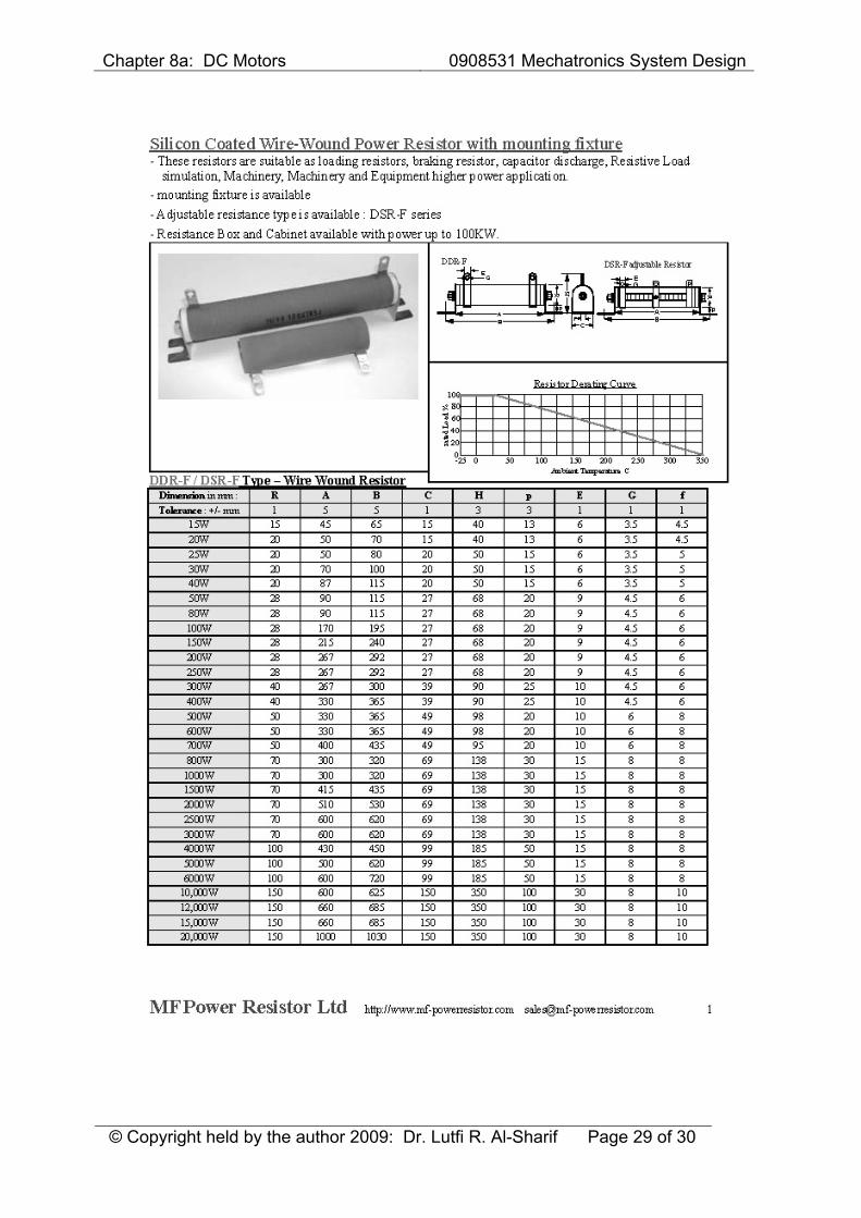
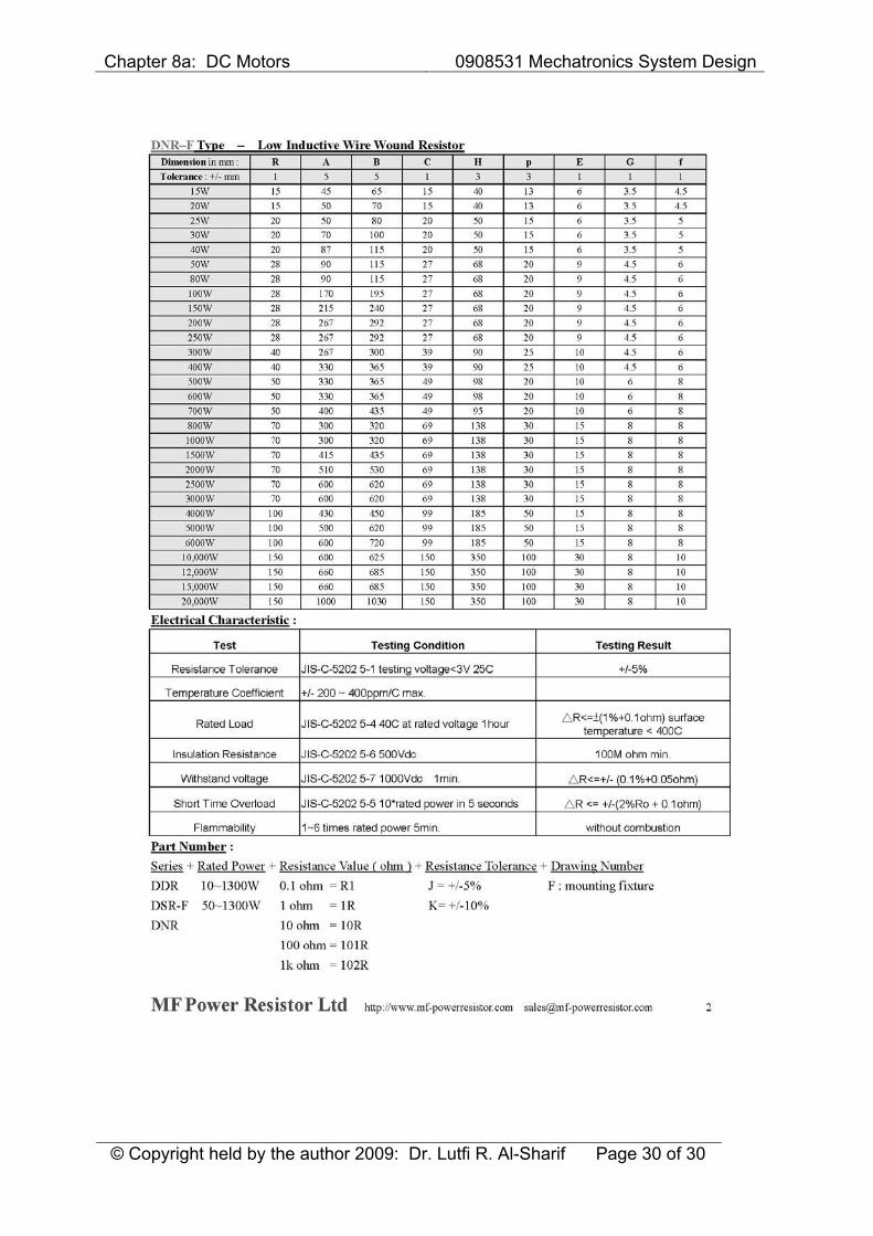
But this is only valid during the starting. If the load starts infrequently then that actual power rating of the resistor will be much lower than this. The next two pages show a datasheet for wire wound resistors that can be used for such an application.
Chapter 8a: DC Motors 0908531 Mechatronics System Design
© Copyright held by the author 2009: Dr. Lutfi R. Al-Sharif Page 29 of 30
Chapter 8a: DC Motors 0908531 Mechatronics System Design
© Copyright held by the author 2009: Dr. Lutfi R. Al-Sharif Page 30 of 30