Embed Size (px)
Citation preview
Internal Flow 1
Chapter 8
Convection: Internal Flow
Internal Flow 2
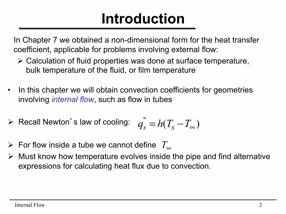
Introduction In Chapter 7 we obtained a non-dimensional form for the heat transfer coefficient, applicable for problems involving external flow: Ø Calculation of fluid properties was done at surface temperature,
bulk temperature of the fluid, or film temperature
• In this chapter we will obtain convection coefficients for geometries involving internal flow, such as flow in tubes
Ø Recall Newton’s law of cooling:
Ø For flow inside a tube we cannot define Ø Must know how temperature evolves inside the pipe and find alternative
expressions for calculating heat flux due to convection.
)("∞−= TThq ss
∞T

Internal Flow 3
Flow Conditions for Internal Flow
• Onset of turbulent flow at 2300Re ≈µ
ρ= DumD
• Hydrodynamic entry length: – Laminar flow
– Turbulent flow
Dhfd Dx Re05.0/, ≈
10/, >Dx hfd
∂u/∂x =0Hydrodynamic entry length
Internal Flow 4
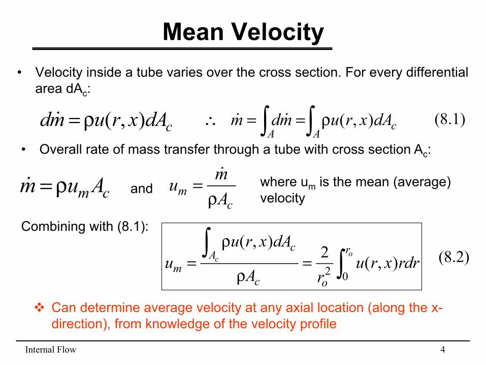
Mean Velocity • Velocity inside a tube varies over the cross section. For every differential
area dAc:
∫∫ ρ==∴A
cA
dAxrumdm ),( !!cdAxrumd ),(ρ=!• Overall rate of mass transfer through a tube with cross section Ac:
cmAum ρ=! and c
m Amuρ
=! where um is the mean (average)
velocity
(8.1)
Combining with (8.1):
∫∫
=ρ
ρ=
ocr
oc
Ac
m rdrxrurA
dAxruu
02 ),(2),(
v Can determine average velocity at any axial location (along the x-direction), from knowledge of the velocity profile
(8.2)
Internal Flow 5
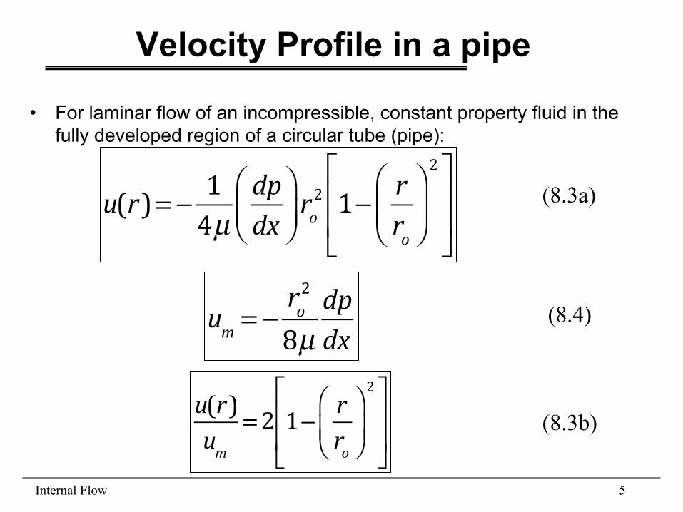
Velocity Profile in a pipe
• For laminar flow of an incompressible, constant property fluid in the fully developed region of a circular tube (pipe):
u(r)= − 1
4µdpdx
⎛⎝⎜
⎞⎠⎟ro2 1− r
ro
⎛
⎝⎜⎞
⎠⎟
2⎡
⎣
⎢⎢
⎤
⎦
⎥⎥
um = −
ro2
8µdpdx
(8.3a)
(8.4)
u(r)um
=2 1− rro
⎛
⎝⎜⎞
⎠⎟
2⎡
⎣
⎢⎢
⎤
⎦
⎥⎥
(8.3b)
Internal Flow 6
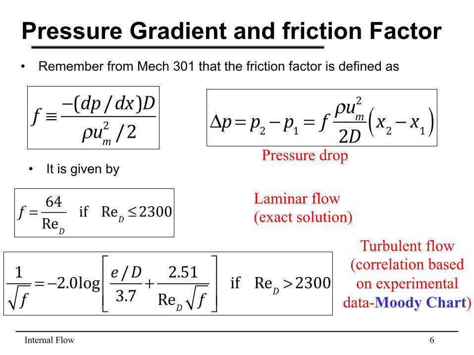
Pressure Gradient and friction Factor • Remember from Mech 301 that the friction factor is defined as
f ≡ −(dp/dx)D
ρum2 /2
f = 64
ReDif ReD ≤2300
• It is given by
1f= −2.0log e/D
3.7 + 2.51ReD f
⎡
⎣⎢⎢
⎤
⎦⎥⎥if ReD >2300
Laminar flow (exact solution)
Turbulent flow (correlation based on experimental
data-Moody Chart)
Δp= p2 − p1 = f
ρum2
2D x2 − x1( )Pressure drop
Internal Flow 7
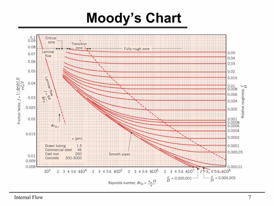
Moody’s Chart
Internal Flow 8
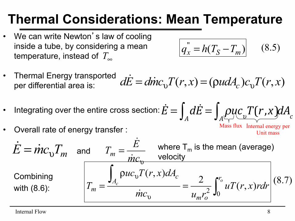
Thermal Considerations: Mean Temperature • We can write Newton’s law of cooling
inside a tube, by considering a mean temperature, instead of ∞T
)("mSx TThq −=
• Thermal Energy transported per differential area is: ),()(),( xrTcudAxrTcmdEd c υυ ρ== !!
Combining with (8.6): ∫
∫=
ρ=
υ
υocr
om
Ac
m rdrxruTrucm
dAxrTucT
02 ),(2),(
!
• Overall rate of energy transfer :
υ=
cmETm !
!where Tm is the mean (average) velocity mTcmE υ= !! and
(8.5)
(8.7)
• Integrating over the entire cross section: !E = d !E
A∫ = ρucυT(r ,x)A∫ dAcMass flux İnternal energy per
Unit mass
Internal Flow 9
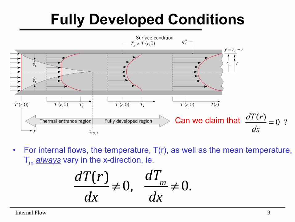
Fully Developed Conditions
• For internal flows, the temperature, T(r), as well as the mean temperature, Tm always vary in the x-direction, ie.
dT(r)dx
≠0, dTmdx
≠0.
Can we claim that ? 0)( =dxrdT
Internal Flow 10
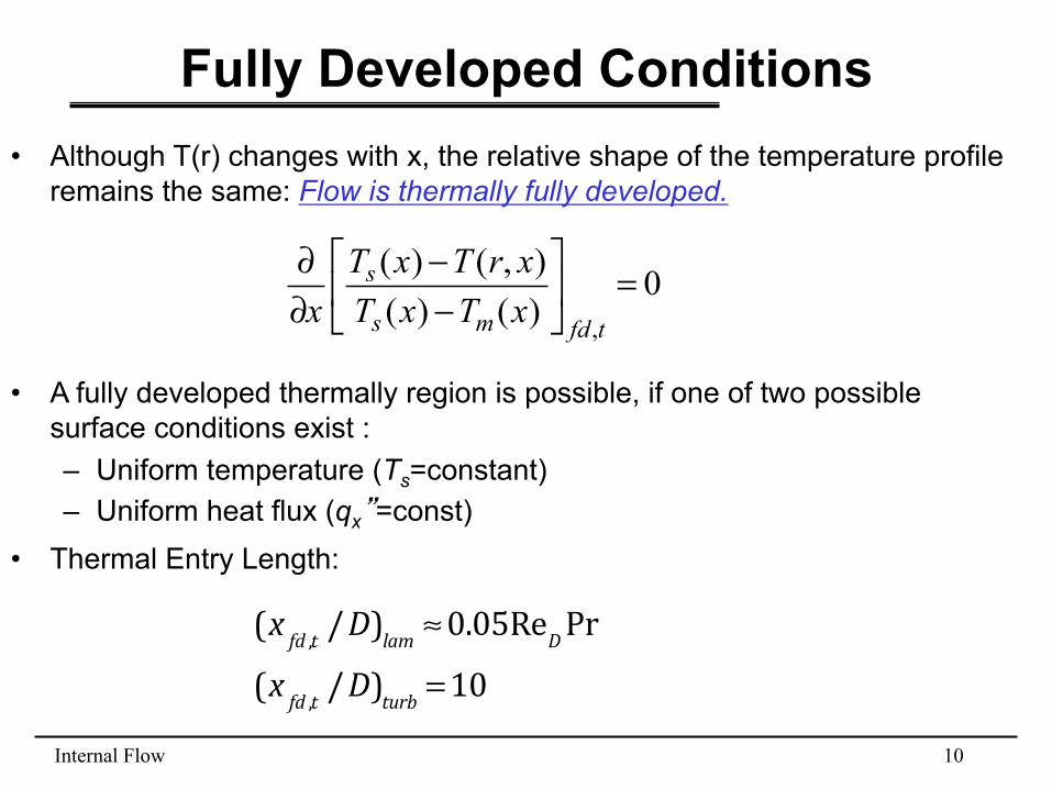
Fully Developed Conditions
• A fully developed thermally region is possible, if one of two possible surface conditions exist : – Uniform temperature (Ts=constant) – Uniform heat flux (qx”=const)
(x fd ,t /D)lam ≈0.05ReDPr(x fd ,t /D)turb =10
• Although T(r) changes with x, the relative shape of the temperature profile remains the same: Flow is thermally fully developed.
0)()(),()(
,
=⎥⎦
⎤⎢⎣
⎡−−
∂∂
tfdms
s
xTxTxrTxT
x
• Thermal Entry Length:
Internal Flow 11
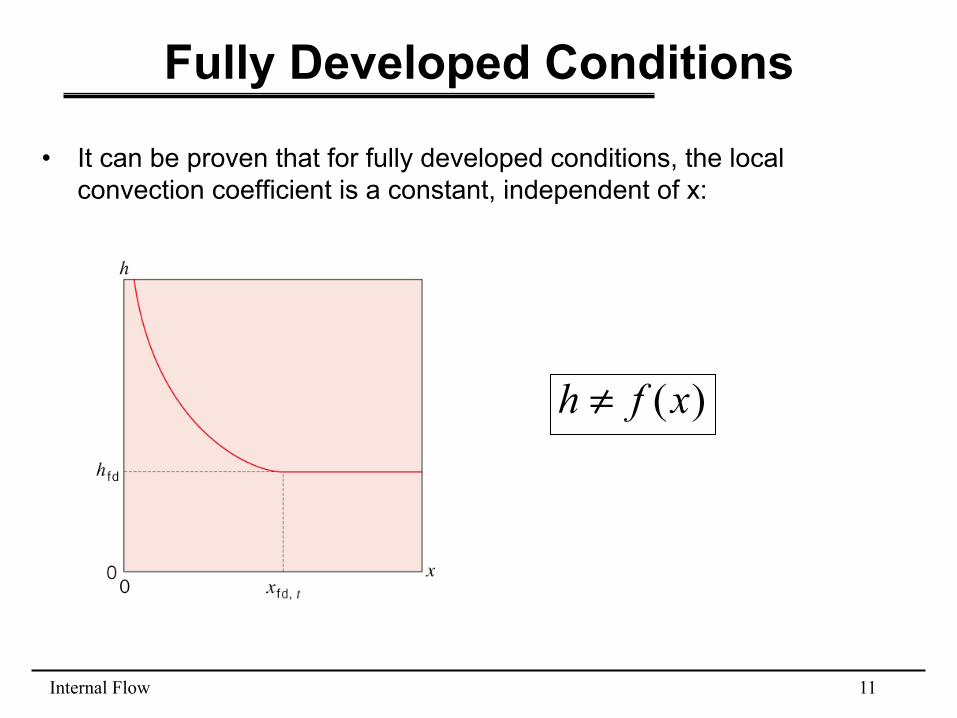
Fully Developed Conditions
• It can be proven that for fully developed conditions, the local convection coefficient is a constant, independent of x:
)(xfh ≠
Internal Flow 12
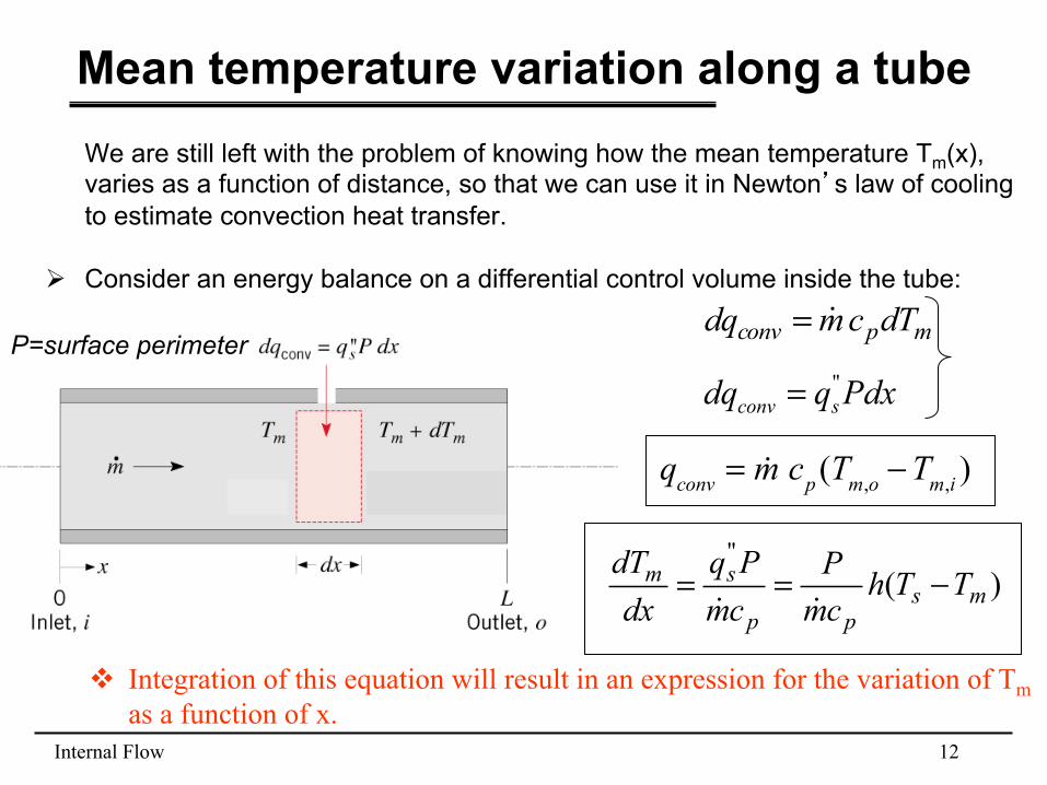
Mean temperature variation along a tube We are still left with the problem of knowing how the mean temperature Tm(x), varies as a function of distance, so that we can use it in Newton’s law of cooling to estimate convection heat transfer.
Ø Consider an energy balance on a differential control volume inside the tube:
mpconv dTcmdq !=P=surface perimeter
"conv sdq q Pdx=
)("
mspp
sm TThcmP
cmPq
dxdT
−==!!
v Integration of this equation will result in an expression for the variation of Tm as a function of x.
qconv = !m cp (Tm,o −Tm,i )
Internal Flow 13
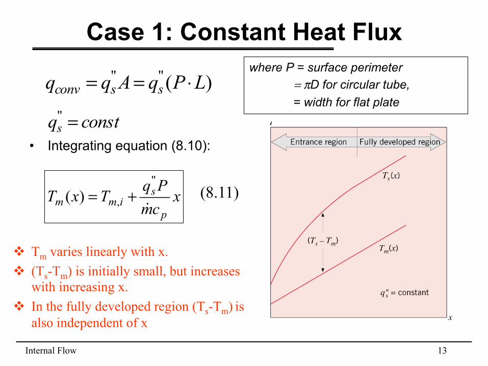
Case 1: Constant Heat Flux
• Integrating equation (8.10):
)("" LPqAqq ssconv ⋅==
xcmPqTxTp
simm !
"
,)( += (8.11)
where P = surface perimeter = πD for circular tube, = width for flat plate
constqs ="
v Tm varies linearly with x. v (Ts-Tm) is initially small, but increases
with increasing x. v In the fully developed region (Ts-Tm) is
also independent of x
Internal Flow 14
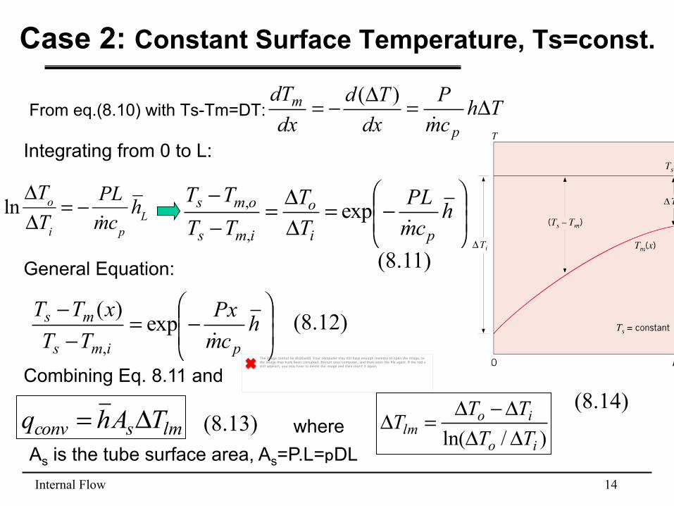
Case 2: Constant Surface Temperature, Ts=const.
From eq.(8.10) with Ts-Tm=DT: ThcmP
dxTd
dxdT
p
m Δ=Δ−=!
)(
Integrating from 0 to L:
⎟⎟⎠
⎞⎜⎜⎝
⎛−=
−− h
cmPx
TTxTT
pims
ms!
exp)(
,
General Equation:
⎟⎟⎠
⎞⎜⎜⎝
⎛−=
ΔΔ=
−−
hcmPL
TT
TTTT
pi
o
ims
oms
!exp
,
,
lmsconv TAhq Δ= where )/ln( io
iolm TT
TTTΔΔΔ−Δ
=Δ(8.13) (8.14)
(8.12)
As is the tube surface area, As=P.L=pDL
lnΔTo
ΔTi
= − PL!mcp
hL
The image cannot be displayed. Your computer may not have enough memory to open the image, or the image may have been corrupted. Restart your computer, and then open the file again. If the red x still appears, you may have to delete the image and then insert it again.
Combining Eq. 8.11 and
(8.11)
Internal Flow 15
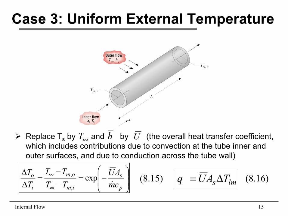
Case 3: Uniform External Temperature
Ø Replace Ts by and by (the overall heat transfer coefficient, which includes contributions due to convection at the tube inner and outer surfaces, and due to conduction across the tube wall)
∞T h U
⎟⎟⎠
⎞⎜⎜⎝
⎛−=
−−
=ΔΔ
∞
∞
p
s
im
om
i
o
cmAU
TTTT
TT
!exp
,
,lms TAUq Δ=(8.15) (8.16)
Internal Flow 16
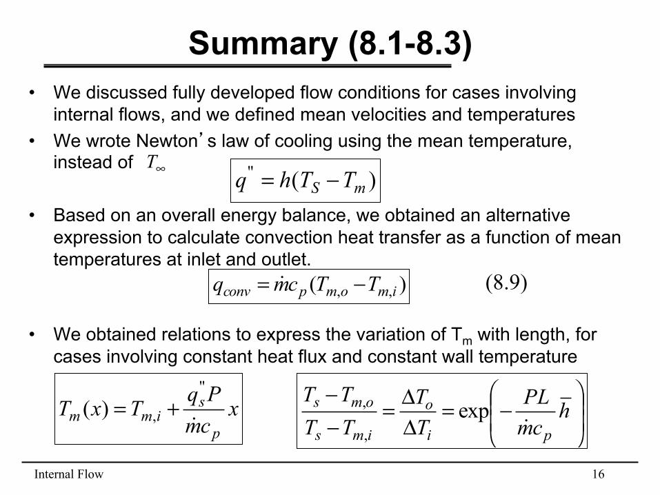
Summary (8.1-8.3) • We discussed fully developed flow conditions for cases involving
internal flows, and we defined mean velocities and temperatures • We wrote Newton’s law of cooling using the mean temperature,
instead of
• Based on an overall energy balance, we obtained an alternative expression to calculate convection heat transfer as a function of mean temperatures at inlet and outlet.
• We obtained relations to express the variation of Tm with length, for
cases involving constant heat flux and constant wall temperature
∞T )("mS TThq −=
)( ,, imompconv TTcmq −= !
xcmPqTxTp
simm !
"
,)( += ⎟⎟⎠
⎞⎜⎜⎝
⎛−=
ΔΔ=
−−
hcmPL
TT
TTTT
pi
o
ims
oms
!exp
,
,
(8.9)
Internal Flow 17
Summary (8.1-8.3)
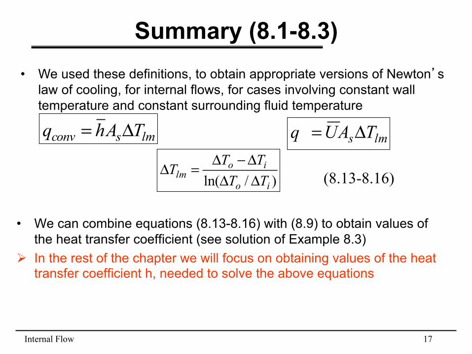
• We can combine equations (8.13-8.16) with (8.9) to obtain values of the heat transfer coefficient (see solution of Example 8.3)
Ø In the rest of the chapter we will focus on obtaining values of the heat transfer coefficient h, needed to solve the above equations
• We used these definitions, to obtain appropriate versions of Newton’s law of cooling, for internal flows, for cases involving constant wall temperature and constant surrounding fluid temperature
lmsconv TAhq Δ= lms TAUq Δ=
)/ln( io
iolm TT
TTTΔΔΔ−Δ
=Δ (8.13-8.16)
Internal Flow 18
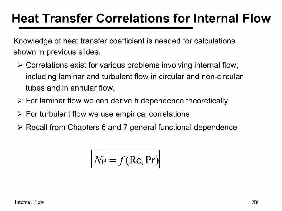
Heat Transfer Correlations for Internal Flow Knowledge of heat transfer coefficient is needed for calculations shown in previous slides.
Ø Correlations exist for various problems involving internal flow, including laminar and turbulent flow in circular and non-circular tubes and in annular flow.
Ø For laminar flow we can derive h dependence theoretically
Ø For turbulent flow we use empirical correlations
Ø Recall from Chapters 6 and 7 general functional dependence
Pr)(Re,fNu =
20
Internal Flow 19
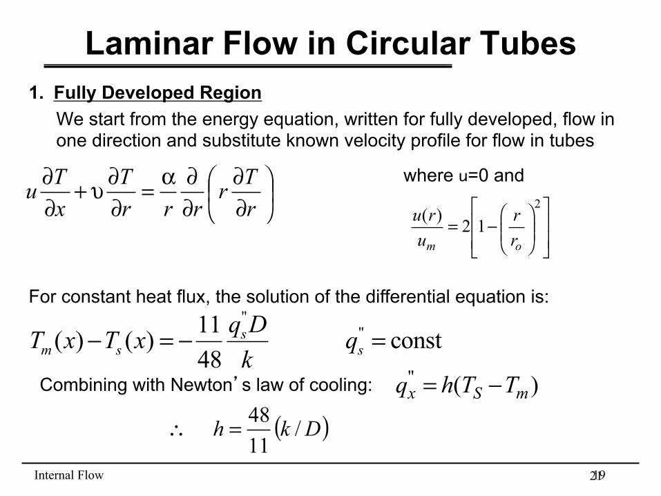
Laminar Flow in Circular Tubes 1. Fully Developed Region
We start from the energy equation, written for fully developed, flow in one direction and substitute known velocity profile for flow in tubes
⎟⎠⎞⎜
⎝⎛
∂∂
∂∂α=
∂∂υ+
∂∂
rTr
rrrT
xTu
21
where u=0 and
⎥⎥⎦
⎤
⎢⎢⎣
⎡⎟⎟⎠
⎞⎜⎜⎝
⎛−=
2
12)(
om rr
uru
For constant heat flux, the solution of the differential equation is: "
"11( ) ( ) const 48
sm s s
q DT x T x qk
− = − =
Combining with Newton’s law of cooling: )("mSx TThq −=
( )Dkh /1148=∴

Internal Flow 20
Laminar Flow in Circular Tubes
• For cases involving uniform heat flux:
constqkhDNu sD ==≡ " 36.4
• For cases involving constant surface temperature:
constTNuD == s 66.3
(8.17)
(8.18)
k should be evaluated at Tm
Internal Flow 21
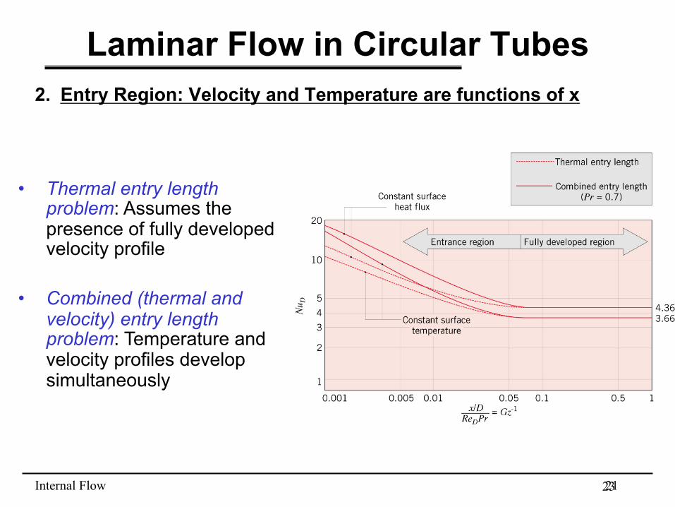
Laminar Flow in Circular Tubes 2. Entry Region: Velocity and Temperature are functions of x
• Thermal entry length problem: Assumes the presence of fully developed velocity profile
• Combined (thermal and velocity) entry length problem: Temperature and velocity profiles develop simultaneously
23
Internal Flow 22
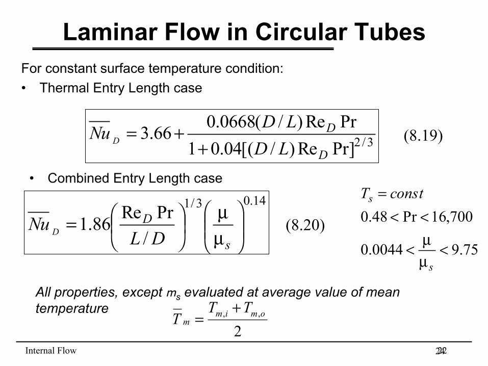
Laminar Flow in Circular Tubes For constant surface temperature condition: • Thermal Entry Length case
3/2Pr]Re)/[(04.01PrRe)/(0668.066.3
D
D
LDLDNu D +
+=
14.03/1
/PrRe86.1 ⎟⎟⎠
⎞⎜⎜⎝
⎛µµ
⎟⎠⎞⎜
⎝⎛=
s
D
DLNu D
• Combined Entry Length case
75.90044.0
700,16Pr48.0
<µµ<
<<=
s
s constT
All properties, except ms evaluated at average value of mean temperature , ,
2m i m o
mT T
T+
=
(8.19)
(8.20)
24
Internal Flow 23
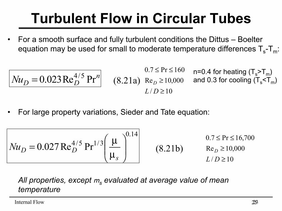
Turbulent Flow in Circular Tubes • For a smooth surface and fully turbulent conditions the Dittus – Boelter
equation may be used for small to moderate temperature differences Ts-Tm:
nDDNu PrRe023.0 5/4=
10/000,10Re160Pr7.0
≥≥
≤≤
DLD
n=0.4 for heating (Ts>Tm) and 0.3 for cooling (Ts<Tm)
• For large property variations, Sieder and Tate equation:
14.03/15/4 PrRe027.0 ⎟⎟⎠
⎞⎜⎜⎝
⎛µµ=s
DDNu10/000,10Re700,16Pr7.0
≥≥
≤≤
DLD
All properties, except ms evaluated at average value of mean temperature
(8.21a)
(8.21b)
25
Internal Flow 24
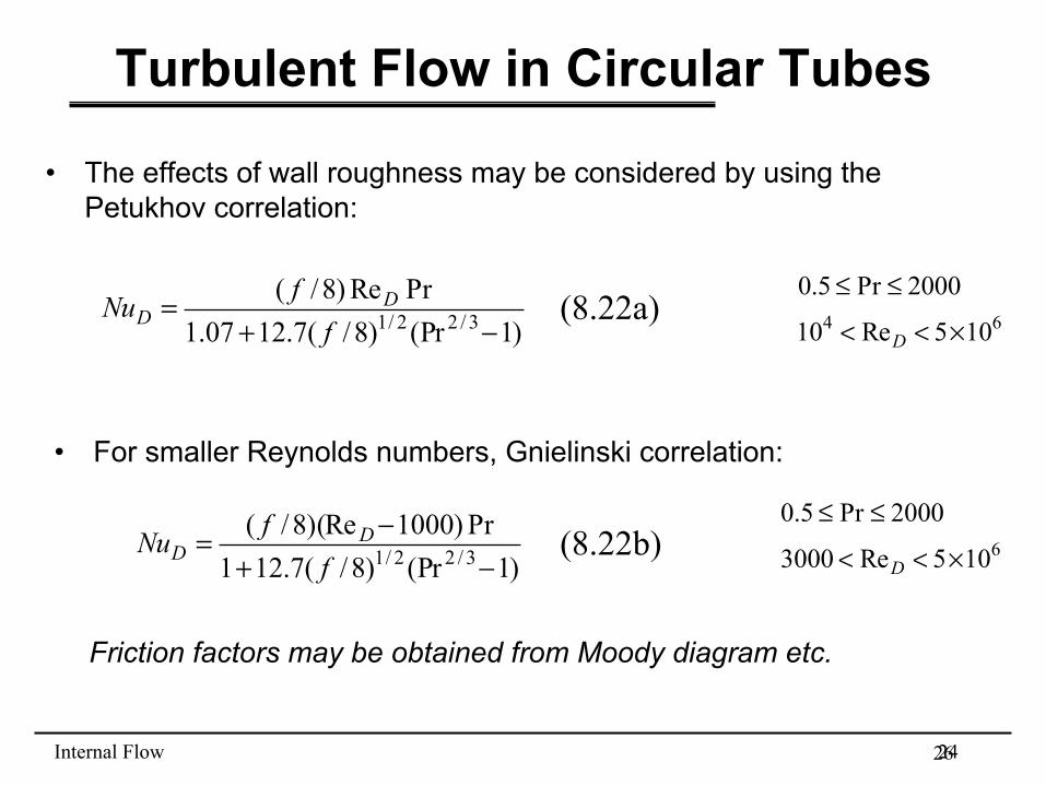
• The effects of wall roughness may be considered by using the Petukhov correlation:
Turbulent Flow in Circular Tubes
)1(Pr)8/(7.1207.1PrRe)8/(
3/22/1 −+=
ffNu D
D 64 105Re10
2000Pr5.0
×<<
≤≤
D
• For smaller Reynolds numbers, Gnielinski correlation:
)1(Pr)8/(7.121Pr)1000)(Re8/(3/22/1 −+
−=f
fNu DD 6105Re3000
2000Pr5.0
×<<
≤≤
D
Friction factors may be obtained from Moody diagram etc.
(8.22a)
(8.22b)
26
Internal Flow 25
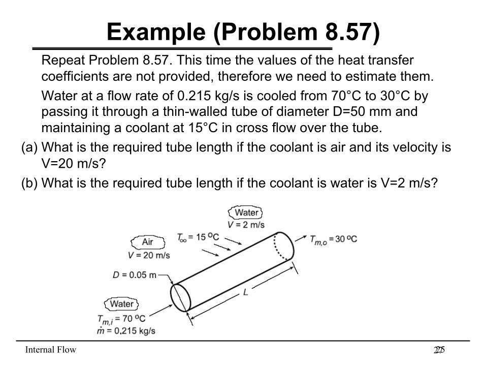
Example (Problem 8.57) Repeat Problem 8.57. This time the values of the heat transfer coefficients are not provided, therefore we need to estimate them. Water at a flow rate of 0.215 kg/s is cooled from 70°C to 30°C by passing it through a thin-walled tube of diameter D=50 mm and maintaining a coolant at 15°C in cross flow over the tube.
(a) What is the required tube length if the coolant is air and its velocity is V=20 m/s?
(b) What is the required tube length if the coolant is water is V=2 m/s?
27
Internal Flow 26
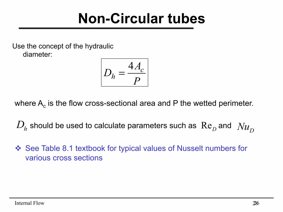
Non-Circular tubes
Use the concept of the hydraulic diameter:
ReD
PAD c
h4=
where Ac is the flow cross-sectional area and P the wetted perimeter. should be used to calculate parameters such as and v See Table 8.1 textbook for typical values of Nusselt numbers for
various cross sections
28
DNuhD
Internal Flow 27
Summary
• Numerous correlations exist for the estimation of the heat transfer coefficient, for various flow situations involving laminar and turbulent flow.
• Always make sure that conditions for which correlations are valid are applicable to your problem.
v Summary of correlations in Table 8.4 of textbook
29