Embed Size (px)
Citation preview

CHAPTER 9 STRUCTURES & SUPPORTS
NORMAG PROZESSTECHNIK 9.1 Index C
GENERAL INFORMATION
For the assembly of apparatus and equipment made of borosilicate glass 3.3 a variable framework structural system
is available. The basic components of this system are galvanised steel or stainless steel tubes of different diameter
as well as structure fittings in different designs and in the corresponding sizes, which are used to join the tubes
together. The fittings are available in closed as well as in open design for easier installation later on. The advantages
of the framework structural system are its high flexibility, low weight, easy assembly and extendibility.
The following table shows the standard sizes of structure tubing which can be delivered in galvanised steel, stainless
steel and blue lacquer and gives an overview of the nomenclature.
Size Exterior pipe
diameter [mm]
Fitting
number
Available in
galvanised steel
Available in
stainless steel
Available in blue
lacquer
¾“ 26.9 5 yes yes yes
1“ 33.7 6 yes yes yes
1 ¼“ 42.4 7 yes yes yes
1 ½“ 48.3 8 yes tubes only on request
2“ 60.3 9 yes tubes only on request
For special applications other materials, such as for example structure tubing and fittings made of fibre-glass or
with an acid-resistant coating, can be used. Our specialist department would be glad to advise you on this.
The structure fittings are used to attach the mounting equipment for the glass components and apparatus, such as
support rings, pipe supports, support brackets or pipe clamps, as anchor and expansion points.
The entire selection of standard deliverable components is described on the following pages and an overview is
presented in the following figure. In addition, we will be happy to offer special designs on top of the product selection
on request.

CHAPTER 9 STRUCTURES & SUPPORTS
NORMAG PROZESSTECHNIK 9.2 Index C
DESIGN OF TUBULAR STRUCTURES
The recommended measurements for
the pipe framework as well as the
recommended diameter for tubular
piping and fittings depend on the
nominal diameter or the diameter and
weight of the glass components to be
attached.
The figure opposite provides a reference
value for which diameter of tubular
piping is recommended for a design
depending on the forces acting on it and
the support spacing.
The stability of a tube framework is dependent on diagonal connections in addition to the correct support spacing.
For this reason a minimum of two sides arranged at right angles to each other are provided with cross-bracing for
rigidity. Additionally, in many cases it is sensible to form a screw connection between the legs of the framework and
the floor or a screw connection with a wall or platform, if available.
The assembly of the glass construction should be carried out
according to the anchor points provided in the framework. These
anchor points should be able to hold the entire weight of the
components attached to them. Vessel holders are used as anchor
points for spherical vessels and standard cylindrical vessels.
Columns can be mounted using their clamp rings by either using tube
frameworks or using fittings with bush inserts. Support brackets are
available for pipelines.
When mounting anchor and expansion points it must be ensured that
borosilicate glass can expand freely. For this reason a decoupling
device, for example bellows, should be included between two anchor
points.
Columns also need to be guided sideways, which can be achieved using an expansion bracket on one of the upper
clamp ring couplings (see figure).
Vibrations that can have an effect on glass components by travelling through the tube framework should be
prevented using suitable means or detached from them. On request, a verification of earthquake safety in
accordance with DIN 4149 can be carried out for the framework or for all apparatus.
Please contact our specialist departments if you have further questions.
1“

CHAPTER 9 STRUCTURES & SUPPORTS
NORMAG PROZESSTECHNIK 9.3 Index C
GLASS PIPELINE SUPPORT INTERVALS
Pipelines are mounted using pipe supports or pipe clamps. Horizontal as well as vertical pipelines have to be
supported at specific distances in order to avoid forces on the pipes due to sag or sideways kinking (for example
before and after bellows): The maximum support spacing for horizontal piping is dependent on the weight of the
medium and is presented in the following table.
DN pipeline Maximum support spacing lmax for medium [mm]
gaseous liquid ρ = 1 liquid ρ = 1,8
15 1.500 1.500 1.000
25 2.000 2.000 1.500
40 2.500 2.000 1.500
50 2.500 2.000 1.500
80 3.000 2.000 1.500
100 3.000 2.500 2.000
150 3.000 2.000 2.000
200 3.000 2.000 1.500
225 3.000 2.000 1.500
300 3.000 2.000 1.500
The support spacing for vertical lengths of pipeline should not exceed 5,000 mm.
Floating bearings are the type of pipe support used. Weights of vertical lengths of pipeline are to be secured using
anchor points like support brackets.
lmax

CHAPTER 9 STRUCTURES & SUPPORTS
NORMAG PROZESSTECHNIK 9.4 Index C
An overview of the various structure and support items is shown in the following:

CHAPTER 9 STRUCTURES & SUPPORTS
NORMAG PROZESSTECHNIK 9.5 Index C
STRUCTURE TUBINGS
Standard galvanised steel tubing’s are available (type KT), as well as type KTS stainless steel tubes (1.4571) in
accordance with DIN EN 10296. The necessary length is selected, as in the following examples, by using a four-
digit length unit entered after the item number. The maximal length is 6,000 mm.
Product description: Item number Examples
Tubular piping ¾“, stainless steel, length 400 mm KTS Øtube - ltube KTS 5-0400
Tubular piping 1 ¼“, galvanised steel, length 1,200 mm KT Øtube- ltube KT 7-1200
Size Item no.
Galvanised steel
Item no.
Stainless steel
¾“ KT 5 KTS 5
1“ KT 6 KTS 6
1 ¼“ KT 7 KTS 7
1 ½“ KT 8 KTS 8
2“ KT 9 KTS 9
TUBE PLUGS
In order to close frame tubes, the following plastic tube plugs can be ordered.
Size Item no.
¾“ KPT 5
1“ KPT 6
1 ¼“ KPT 7
1 ½“ KPT 8
2“ KPT 9
CHAPTER 9 STRUCTURES & SUPPORTS
NORMAG PROZESSTECHNIK 9.6 Index C
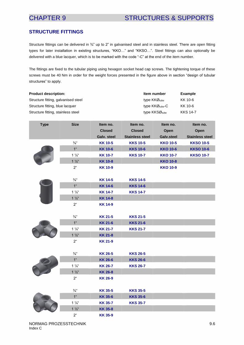
STRUCTURE FITTINGS
Structure fittings can be delivered in ¾” up to 2” in galvanised steel and in stainless steel. There are open fitting
types for later installation in existing structures, “KKO…” and “KKSO…”. Steel fittings can also optionally be
delivered with a blue lacquer, which is to be marked with the code “-C” at the end of the item number.
The fittings are fixed to the tubular piping using hexagon socket head cap screws. The tightening torque of these
screws must be 40 Nm in order for the weight forces presented in the figure above in section “design of tubular
structures” to apply.
Product description: Item number Example
Structure fitting, galvanised steel type KKØtube KK 10-6
Structure fitting, blue lacquer type KKØtube-C KK 10-6
Structure fitting, stainless steel type KKSØtube KKS 14-7
Type Size Item no.
Closed
Galv. steel
Item no.
Closed
Stainless steel
Item no.
Open
Galv.steel
Item no.
Open
Stainless steel
¾“ KK 10-5 KKS 10-5 KKO 10-5 KKSO 10-5
1“ KK 10-6 KKS 10-6 KKO 10-6 KKSO 10-6
1 ¼“ KK 10-7 KKS 10-7 KKO 10-7 KKSO 10-7
1 ½“ KK 10-8 KKO 10-8
2“ KK 10-9 KKO 10-9
¾“ KK 14-5 KKS 14-5
1“ KK 14-6 KKS 14-6
1 ¼“ KK 14-7 KKS 14-7
1 ½“ KK 14-8
2“ KK 14-9
¾“ KK 21-5 KKS 21-5
1“ KK 21-6 KKS 21-6
1 ¼“ KK 21-7 KKS 21-7
1 ½“ KK 21-8
2“ KK 21-9
¾“ KK 26-5 KKS 26-5
1“ KK 26-6 KKS 26-6
1 ¼“ KK 26-7 KKS 26-7
1 ½“ KK 26-8
2“ KK 26-9
¾“ KK 35-5 KKS 35-5
1“ KK 35-6 KKS 35-6
1 ¼“ KK 35-7 KKS 35-7
1 ½“ KK 35-8
2“ KK 35-9

CHAPTER 9 STRUCTURES & SUPPORTS
NORMAG PROZESSTECHNIK 9.7 Index C
Type Size Item no.
Closed
Galv. steel
Item no.
Closed
Stainless steel
Item no.
Open
Galv. steel
Item no.
Open
Stainless steel
¾“ KK 45-5 KKS 45-5 KKO 45-5 KKSO 45-5
1“ KK 45-6 KKS 45-6 KKSO 45-65
1 ¼“ auf ¾“ KKO 45-75 KKSO 45-75
1 ¼“ KK 45-7 KKS 45-7 KKO 45-7
1 ½“ KK 45-8
2“ auf ¾“ KKO 45-95
2“ auf 1 ¼“ KKO 45-97
2“ KK 45-9
¾“ KK 49-5 KKS 49-5
1“ KK 49-6 KKS 49-6
1 ¼“ KK 49-7 KKS 49-7
1 ½“ KK 49-8
2“ KK 49-9
¾“ KK 50-5 KKO 50-5 KKSO 50-5
1“ KK 50-6 KKSO 50-6
1 ¼“ KK 50-7 KKS 50-7 KKO 50-7 KKSO 50-7
1 ½“ KK 50-8
2“ KK 50-9 KKO 50-9
¾“ KK 173-5 KKO 173-5 KKSO 173-5
1“ KK 173-6 KKSO 173-6
1 ¼“ KK 173-7 KKO 173-7 KKSO 173-7
1 ½“ KK 173-8
2“ KK 173-9 KKO 173-9
¾“ KK 62-5 KKS 62-5
1“ KK 62-6 KKS 62-6
1 ¼“ KK 62-7 KKS 62-7
1 ½“ KK 62-8
2“ KK 62-9

CHAPTER 9 STRUCTURES & SUPPORTS
NORMAG PROZESSTECHNIK 9.8 Index C
CASTORS FOR APPARATUS STRUCTURES
Alternatively to the type KK62-… tubular piping legs, castors are available for mobile apparatus. The castors are
connected directly to tubular piping using a bush insert and a structure fitting (type KK(S)14-…), that are included
in the delivery. The castor housings are made either from galvanised steel or stainless steel. Standard designs of
castors for heavy loads are made out of stainless steel. The wheels have a durable polyurethane wheel tread -
optionally in electrically conductive design -, leave no traces, and have a Shore A hardness of 94°. The castors
come as swivel castors in standard design, and swivel castors with brakes as well as fixed castors are available as
options. It is recommended to use at least two brakes on one mobile framework with four castors.
An electrically conductive variant is available as an option.
Description: Item number Examples
Swivel castor, galvanised steel KC Øtube KC 7
Swivel castor, stainless steel KCS Øtube KCS 7
Swivel castor, galvanised steel, with brake KC Øtube -O1 KC 7-O1
Fixed castor, galvanised steel KC Øtube -O2 KC 7-O2
Swivel castor, galvanised steel, electrically conductive design KC Øtube -M1 KC 7-M1
If needed there are also other castor designs available. Please contact our specialist department about this.
D
[mm]
d B
[mm]
H
[mm]
Load capacity per
steel/stainless
steel castor [kg] **
Total load
capacity of
mobile
apparatus* **
Item no.
Steel
Item no.
Stainless
steel
¾“ 100 M12 32 133/125 120/150 360/450 KC 5 KCS 5
1“ 100 M12 32 133/125 120/150 360/450 KC 6 KCS 6
1 ¼“ 100 M12 32 133/125 120/150 360/450 KC 7 KCS 7
1 ¼“ 125 M12 40 150 250 750 - KCH 7
*when using four castors, safety factor included **the load capacity is reduced by 35 % when choosing the conductive version
Castors KC.. / KCS.. castors, heavy duty, KCH 7

CHAPTER 9 STRUCTURES & SUPPORTS
NORMAG PROZESSTECHNIK 9.9 Index C
BUSH INSERTS
Bush inserts form a transition between structure fittings and mounting brackets using threaded rods. They are
primarily used to join support brackets or flange rings to the basic framework in conjunction with 90° fittings. The
bushings are made of stainless steel, and optionally from steel.
Description: Item number Examples
Bush insert, stainless steel KKN Øtube-M...-H KKN 7-M08-50
Bush insert, steel KKN Øtube-M...-H -M2 KKN 8-M12-50-M2
Size Thread H
[mm]
Item no.
¾“
M8
30
KKN 5-M08-30
M10 KKN 5-M10-30
M12 KKN 5-M12-30
1“
M8
35
KKN 6-M08-35
M10 KKN 6-M10-35
M12 KKN 6-M12-35
1 ¼“
M8
50
KKN 7-M08-50
M10 KKN 7-M10-50
M12 KKN 7-M12-50
M16 KKN 7-M16-50
1 ½“
M8
50
KKN 8-M08-50
M10 KKN 8-M10-50
M12 KKN 8-M12-50
M16 KKN 8-M16-50
2“
M8
60
KKN 9-M08-60
M10 KKN 9-M10-60
M12 KKN 9-M12-60
M16 KKN 9-M16-60
KKN... bush inserts

CHAPTER 9 STRUCTURES & SUPPORTS
NORMAG PROZESSTECHNIK 9.10 Index C
PIPE SUPPORTS
Pipe supports consist of a two-part rubber insert, a round bracket and a retaining plate with a tubular piping
connection. The pipe supports are available in galvanised steel or in stainless steel designs.
DN H
[mm]
H1
[mm]
B
[mm]
B1 D
Item no.
Galv. steel
Item no.
Stainl. steel
15 69 35,5 74 20 ¾“ / Ø28 KHR 015 KHRS 015
25 69 35,5 74 20 ¾“ / Ø28 KHR 025 KHRS 025
40 98 50 103 20 ¾“ / Ø28 KHR 040 KHRS 040
50 98 50 103 20 ¾“ / Ø28 KHR 050 KHRS 050
80 187 94,5 194 20 ¾“ / Ø28 KHR 080 KHRS 080
100 187 94,5 194 20 ¾“ / Ø28 KHR 100 KHRS 100
150 248 125,5 259 40 ¾“ / Ø28 KHR 150 KHRS 150
200 299 150,5 309 40 1 ¼“ / Ø44 KHR 200 KHRS 200
PIPE CLAMPS
Pipe clamps are an alternative to pipe supports. The connection to the tube framework or a wall is achieved by
using a threaded rod and not using structure tubes. The pipe clamps are two-part and completely lined inside with
rubber padding and available in either galvanised steel or stainless steel.
DN H
[mm]
H1
[mm]
B
[mm]
B1 M Item no.
Galv. steel
Item no.
Stainl. steel
15 55 32 70 23 M10 KPC 015 KPCS 015
25 66 38 80 23 M10 KPC 025 KPCS 025
40 83 46 98 23 M12 KPC 040 KPCS 040
50 96 53 111 23 M12 KPC 050 KPCS 050
80 124 65 144 28 M12 KPC 080 KPCS 080
100 154 82 176 28 M12 KPC 100 KPCS 100
150 202 106 226 28 M12 KPC 150 KPCS 150
200 257 135 306 46 M12 KPC 200 KPCS 200
300 350 183 394 46 M12 KPC 300 KPCS 300
KPC…/ KPCS…pipe clamps
KHR…/ KHRS…pipe supports

CHAPTER 9 STRUCTURES & SUPPORTS
NORMAG PROZESSTECHNIK 9.11 Index C
SUPPORT BRACKETS
Support brackets are primarily used to secure the weight of vertical pipelines and act as anchor points. In order to
avoid tensile strain glass pipelines should be mounted at the lowest point.
The support brackets are provided with several bores or elongated holes for the various pitch circles of PF, KF and
KF silumin clamp rings. The nominal diameter 80 can also be ordered for ¾“ instead of for 1 ¼“.
Description: Item number Examples
Support bracket, galvanised steel KHB DN KHB 080
Support bracket, galvanised steel, ¾“ connection KHB DN-O5 KHB 080-O5
DN H
[mm]
H1
[mm]
TK
[mm]
nxM
[mm]
D
Item no.
Galv. steel
Item no.
Stainl. steel
15 161 69 50 1),2),3) 3xØ9 ¾“ KHB 015 KHBS 015
25 178 86
70 1) 3xØ10
¾“ KHB 025 KHBS 025 85 2) 3xØ10
75 3) 3xØ10
40 198 106
86 1) 3xØ10
¾“ KHB 040 KHBS 040 110 2) 3xØ10
100 3) 3xØ10
50 204 112
98 1) 3xØ10
¾“ KHB 050 KHBS 050 125 2) 3xØ10
110 3) 3xØ10
80 253 161
133 1) 3xØ10
¾“ KHB 080-O5 KHBS 080-O5 160 2) 3xØ10
150 3) 3xØ10
80 262 160
133 1) 3xØ10
1 ¼“ KHB 080 KHBS 080 160 2) 3xØ10
150 3) 3xØ10
100 280 177
178 1) 3xØ10
1 ¼“ KHB 100 KHBS 100 180 2) 3xØ10
170 3) 3xØ10
150 340 238
254 1) 3xØ10
1 ¼“ KHB 150 KHBS 150 240 2) 3xØ10
225 3) 3xØ10
200 310 208 295 1), 2) 3xØ10
1 ¼“ KHB 200 KHBS 200 280 3) 3xØ10
300 363 260 400 1), 2) 3xØ10
1 ¼“ KHB 300 KHBS 300 395 3) 3xØ10
1) Pitch circle for PF system, 2) Pitch circle for KF system, 3) Pitch circle for silumin flange rings
KHB…/ KHBS…support bracket

CHAPTER 9 STRUCTURES & SUPPORTS
NORMAG PROZESSTECHNIK 9.12 Index C
LOWER SUPPORT RINGS
Lower support rings serve to hold and transfer weight load of vertical pipelines, vessels and apparatus in a tube
framework. Fixation to the framework is carried out either by screwing the support rings to flange couplings or by
using threaded rods and insert bushes on the outer brackets. Support rings always act as anchor points which
should be remembered when carrying out further mounting. A decoupling device, for example bellows, should be
included between two anchor points.
Bores for the connection of PF, KF and silumin flange rings are provided.
The support rings can optionally be delivered as part of an installation kit along with the structure fittings, insert
bushes and screw fixing for installation into an available tube framework. The size of the structure fittings can be
chosen freely.
Description: Item number Examples
Lower support ring, galvanised steel KLS DN KLS 150
Lower support ring, stainless steel KLSS DN KLSS 150
Lower support ring, galvanised steel, incl. structure fitting 1 ½“ KLS DN-O3Øtube KLS 300-O38
Lower support ring, stainless steel, incl. structure fitting ¾“ KLSS DN-O3Øtube KLSS 150-O35
for
[DN]
L
[mm]
L1
[mm]
n x M Item no.
Galv. steel
Item no.
Stainless steel
80 80 125 3 x Ø14 KLS 080 KLSS 080
100 95 135 3 x Ø14 KLS 100 KLSS 100
150 125 165 3 x Ø14 KLS 150 KLSS 150
200 155 190 3 x Ø14 KLS 200 KLSS 200
300 200 245 3 x Ø18 KLS 300 KLSS 300
400 275 298 3 x Ø18 KLS 400 KLSS 400
450 300 340 3 x Ø18 KLS 450 KLSS 450
600 375 400 3 x Ø18 KLS 600 KLSS 600
KL…/ KLSS…lower support ring Option incl. structure fittings

CHAPTER 9 STRUCTURES & SUPPORTS
NORMAG PROZESSTECHNIK 9.13 Index C
SUPPORT RINGS FOR SPHERICAL VESSELS
Support rings are used to hold spherical vessels with a volume of 5 to 20 L. They are made of stainless steel and
have a soft insert to protect the spherical vessel. Support rings are connected to the tube framework using three
bores and their height is therefore easy to adjust.
for spherical
vessel
[l]
L
[mm]
L2
[mm]
H
[mm]
H1
[mm]
TK
[mm]
n x M Item no.
5 220 56 89 12 230 3 x Ø9 KSR 05
10 220 64 112 12 254 3 x Ø9 KSR 10
20 209 104 125 12 295 3 x Ø9 KSR 20
VESSEL HOLDERS
Vessel holders are used to hold spherical vessels with a volume between 50 and 200 L and for cylindrical vessels
with a nominal diameter between 400 and 600. Many sizes can be used for a specific nominal diameter of cylindrical
vessel and for a specific size of spherical vessel. Vessel holders have three bores like support rings. They consist
of aluminium, have a corrosion-proof coating and are provided with felt inserts.
for cylindrical
vessel
[DN]
for spherical
vessel
[l]
D
[mm]
H
[mm]
H1
[mm]
TK
[mm]
n x M Order
number
400 383 215 105 340 3 x Ø14 KST 400
450 50 429 240/255 115 395 3 x Ø14 KST 450/50
600 100 515 315/310 125 400 3 x Ø14 KST 600/100
200 615 360 125 585 3 x Ø14 KST 200
KSR…support rings for spherical vessels
KST…vessel holders

CHAPTER 9 STRUCTURES & SUPPORTS
NORMAG PROZESSTECHNIK 9.14 Index C
SADDLE SUPPORTS
Saddle supports are used mostly to hold up horizontal containers, such as separators or shell and tube heat
exchangers, and are fixed using flange rings. They are made of stainless steel and can be used with a nominal
diameter of 150 both in the PF and KF systems. During assembly it should be ensured that only one saddle
support is used as an anchor point; the second should be mounted as an expansion point to prevent unauthorised
tension in the glass.
Description: Item number Examples
Saddle supports KSA DN KSA 150
Saddle supports, for silumin clamp rings KSA DN-O4 KSA 150-O4
Nominal
diameter
[DN]
L
[mm]
L1 H
[mm]
B
[mm]
B1
[mm]
TK
[mm]
nxM Item no.
150 305 263 200 75 40 240 1) 4xØ11
KSA 150 254 2) 3xØ11
200 305 263 200 75 40 295 4xØ11 KSA 200
300 320 280 180 75 40 400 4xØ11 KSA 300
400 380 320 190 75 40 495 5xØ11 KSA 400
450 405 320 225 112,5 57 585 4xØ11 KSA 450
600 590 500 275 115 57 710 6xØ16 KSA 600
1) Pitch circle for PF system, 2) Pitch circle for KF system
KSA…saddle support

CHAPTER 9 STRUCTURES & SUPPORTS
NORMAG PROZESSTECHNIK 9.15 Index C
LIFTING LUGS
Lifting lugs are attached to horizontal containers in order to move them using appropriate lifting equipment and
transport them to their place of installation. They are made of stainless steel and can be used with a nominal
diameter of 150 both in the PF and KF systems.
Description: Item number Examples
Lifting lugs, for silumin clamp rings KLL DN-O4 KLL 300-O4
Nominal
diameter [DN]
H
[mm]
H1
[mm]
TK
[mm]
NxM Item no.
150 245 180 240 1) 4xØ9
KLL 150 254 2) 4xØ9
200 305 200 295 4xØ11 KLL 200
300 320 200 400 4xØ11 KLL 300
400 405 204 495 4xØ11 KLL 400
450 405 204 285 4xØ11 KLL 450
600 590 250 710 6xØ16 KLL 600
1) Pitch circle for PF system, 2) Pitch circle for KF system
KLL... Lifting lug

CHAPTER 9 STRUCTURES & SUPPORTS
NORMAG PROZESSTECHNIK 9.16 Index C
LIFTING AND LOWERING DEVICE
For many applications, e.g. mobile filters and vessels with stirrers, the lowering of components of the apparatus is
required. This can be achieved with the lifting and lowering device type KLD. To move the components, the flange
connection of the apparatus needs to be opened after which the bottom part of the apparatus can be lowered or
lifted with a crank lever. Optionally, a PTFE-jacketed flange connector (Option O6) with an additional support mount
can be used to fixate the apparatus’ top part. For frequent opening and closing processes the use of a gasket type
CGP is recommended. The device’s standard stroke length is 600 mm but can be modified according to the
requirements. An adjustable stopper can also be used to restrict the movement.
Additional options for the lifting and lowering device are a sideways swinging mechanism (Option O7), stainless
steel fittings (Option O8) as well as a crank lever with an angular gear (Option O9).
For requirements varying from our standards please contact our technical department.
Product name: Item number Examples
Lifting and lowering device KLD DN KLD 300
Lifting and lowering device with PTFE-jacketed counter flange KLD DN-O6 KLD 300-O6
Lifting and lowering device swinging mechanism (L1 + 10mm) KLD DN-O7 KLD 300-O7
Lifting and lowering device, with stainless steel fittings KLD DN-O8 KLD 300-O8
Lifting and lowering device, with angular gear crank lever KLD DN-O9 KLD 300-O9
For cylindrical
vessel
[DN]
Volume
[l]
Max. load
[kg]
L1
[mm]
L2
[mm]
Stroke
[mm]
H
[mm]
Item no.
200 10-20 150 410 350 600 925 KLD 200
300 30-50 180 460 450 600 925 KLD 300
400 50-100 220 500 550 600 925 KLD 400
450 50-100 250 575 630 600 925 KLD 450
Lifting and lowering device KLD…

CHAPTER 9 STRUCTURES & SUPPORTS
NORMAG PROZESSTECHNIK 9.17 Index C
More options and special products are listed below. For details or special requirements, please contact our technical departments.
MACROLON COVERINGS
For further protection of the operating personnel Makrolon coverings can be useful in glass plants at critical points.
These are connected to the frame and act as a splitter and spray protection. For easy access to certain parts of the
plant Makrolon coverings can be carried out with closable openings or moveable.
WELDED FRAMES
For larger loads, for instance as a supporting structure and fixed-point mounting of larger nominal size columns, or
for special applications, such as supporting structures for clean room applications, individual welded frames can be
delivered. For this, there are already some concepts available that can be configured individually according to
customer requirements and project specifications.
MOBILE RACKS FOR RAIL SYSTEMS
For frequent planned replacements of one or more specific sections in columns there is a concept of a castor / rail
system.
For rail systems in autoclave mobile welding racks adapted to the customer's situations can be delivered.

CHAPTER 9 STRUCTURES & SUPPORTS
NORMAG PROZESSTECHNIK 2012 O 9.1 Index B
OPTIONS STRUCTURES
For framework structural components the following options can be chosen in addition to the standard structural
components. Each option chosen must be entered at the end of the item number. Several options can be chosen
and they are presented as far as possible in alphabetical order. In the following table you will find examples of
item numbering for additional options.
Product description: Item number Examples
90° corner joint type 10, 1“, blue lacquer type KKØtube-O1 KK 10-6-O1
Swivel castor with brake, electrically conductive design KC Øtube-M1-O1 KC 7-M1-O1
Saddle support, for silumin clamp rings KSA DN-O4 KSA 150-O4
You can choose from the following options:
OPTION C – COATING
Steel structure fittings without a coating are used as the standard design. Fittings with a blue lacquer are
optionally available.
C = blue lacquer
OPTION M – MATERIAL
The following additional materials can be chosen:
M1 = electrically conductive castor design to protect against electrostatic discharge
M2 = steel design, for items which have a stainless steel standard design
M3 = steel design, galvanised, for items which have a stainless steel standard design
OPTION O – SPECIAL OPTIONS
The following options are offered for certain structural components.
O1 = swivel castor
O2 = fixed castor
O3Øtube= installation kit for lower support ring incl. structure fittings, insert bushes and screw set
O4 = designed with bores for silumin clamp rings where this is not provided in the standard design (for saddle
supports and lifting lugs)
O5 = with a connection for ¾“ tube (for support brackets)