Embed Size (px)
Citation preview
CHAPTER 9. GLOBAL POSITIONING SYSTEM
SECTION I. CONFIGURATION, SIGNALS, AND CODE
The Navigation Satellite Timing and Ranging(NAVSTAR) GPS is configured into space, control,and user segments. Each segment depends upon theother. See figure 9-1.
Originally, the complete space segment was to consist of24 Block II satellites. Block I satellites were considereddevelopmental. Block IIR (Replacement) satellites arebeing developed to provide system operations through
the year 2025. More than 24 satellites are currently inorbit. They are arranged into six orbital planes, eachinclined 55° from the Equator. Each orbital planecontains at least four unevenly spaced satellites orbitingthe Earth twice a day at an altitude of 10,898 miles.Satellites move continuously through their orbit in thesame direction as the Earth’s rotation. They orbit theearth twice in 23 hours, 56 minutes, and 04.091 secondssolar time or 1 24-hour sidereal day.
Figure 9-1. NAVSTAR System Configuration: Space, Control, and User Segments.
9-2 ______________________________________________________________________________________________ MCWP 3-16.7
The control segment consists of five unmannedmonitor / t racking s ta t ions located in Hawaii ,Colorado, Ascension Island, Diego Garcia, andKwajalein. Tracking stations use special receivers totrack each satellite individually. The informationfrom tracking the satellites helps control the satellitesand predict their orbits. Three of the stations transmitinformation back to the satellites. All data collectedat the tracking stations is transmitted to the mastercontrol s tat ion, located at Colorado Springs,Colorado where it is processed and analyzed.Ephemerides, clock corrections, and other messagedata are then transmitted back to the three stations forsubsequent transmittal back to the satellites. Themaster control station is also responsible for the dailymanagement and control of the satellites and theoverall control segment.
The user segment consists of any one with a GPSreceiver. Military and civilian personnel (including theenemy) use these receivers.
Satellite Signals
See figures 9-2 through 9-5.
Carrier Frequencies
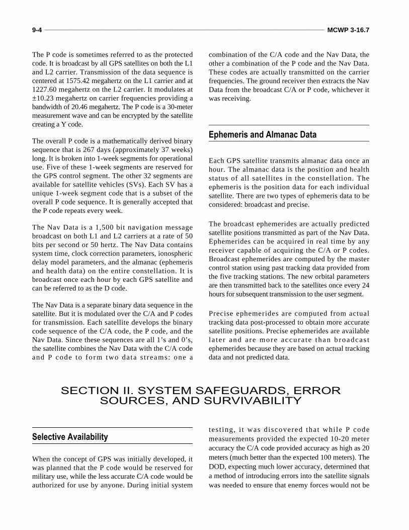
Each GPS satellite broadcasts signals on two spread-spectrum radio frequencies (RFs). These are termedcarrier frequencies because they are modulated withsignal codes “carried” on the radio wave. Thesate l l i te’s onboard a tomic c locks generate a
fundamenta l f r equency o f 10 .23 megaher t z(10,230,000 cycles per second) multiplied by a factorthat produces the actual carrier frequency.
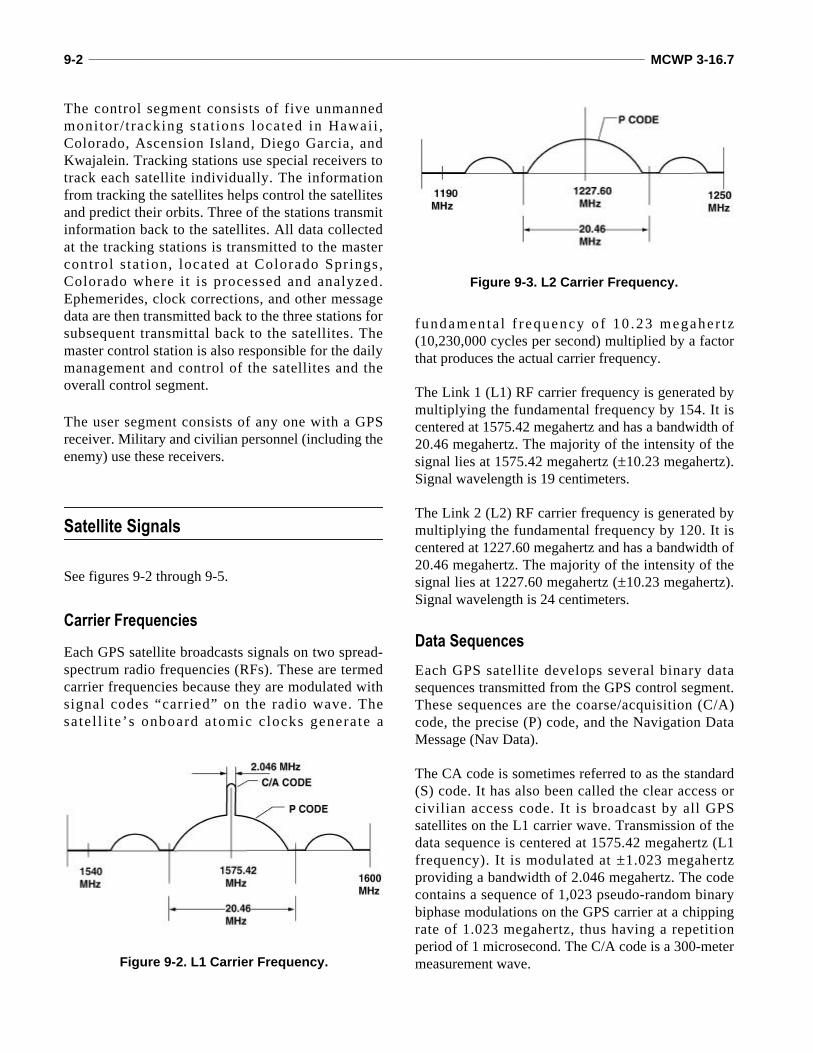
The Link 1 (L1) RF carrier frequency is generated bymultiplying the fundamental frequency by 154. It iscentered at 1575.42 megahertz and has a bandwidth of20.46 megahertz. The majority of the intensity of thesignal lies at 1575.42 megahertz (±10.23 megahertz).Signal wavelength is 19 centimeters.
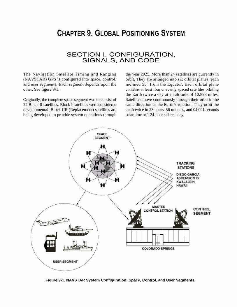
The Link 2 (L2) RF carrier frequency is generated bymultiplying the fundamental frequency by 120. It iscentered at 1227.60 megahertz and has a bandwidth of20.46 megahertz. The majority of the intensity of thesignal lies at 1227.60 megahertz (±10.23 megahertz).Signal wavelength is 24 centimeters.
Data Sequences
Each GPS satellite develops several binary datasequences transmitted from the GPS control segment.These sequences are the coarse/acquisition (C/A)code, the precise (P) code, and the Navigation DataMessage (Nav Data).
The CA code is sometimes referred to as the standard(S) code. It has also been called the clear access orcivilian access code. It is broadcast by all GPSsatellites on the L1 carrier wave. Transmission of thedata sequence is centered at 1575.42 megahertz (L1frequency). It is modulated at ±1.023 megahertzproviding a bandwidth of 2.046 megahertz. The codecontains a sequence of 1,023 pseudo-random binarybiphase modulations on the GPS carrier at a chippingrate of 1.023 megahertz, thus having a repetitionperiod of 1 microsecond. The C/A code is a 300-metermeasurement wave. Figure 9-2. L1 Carrier Frequency.
Figure 9-3. L2 Carrier Frequency.
Marine Artillery Survey Operations ________________________________________________________________________ 9-3
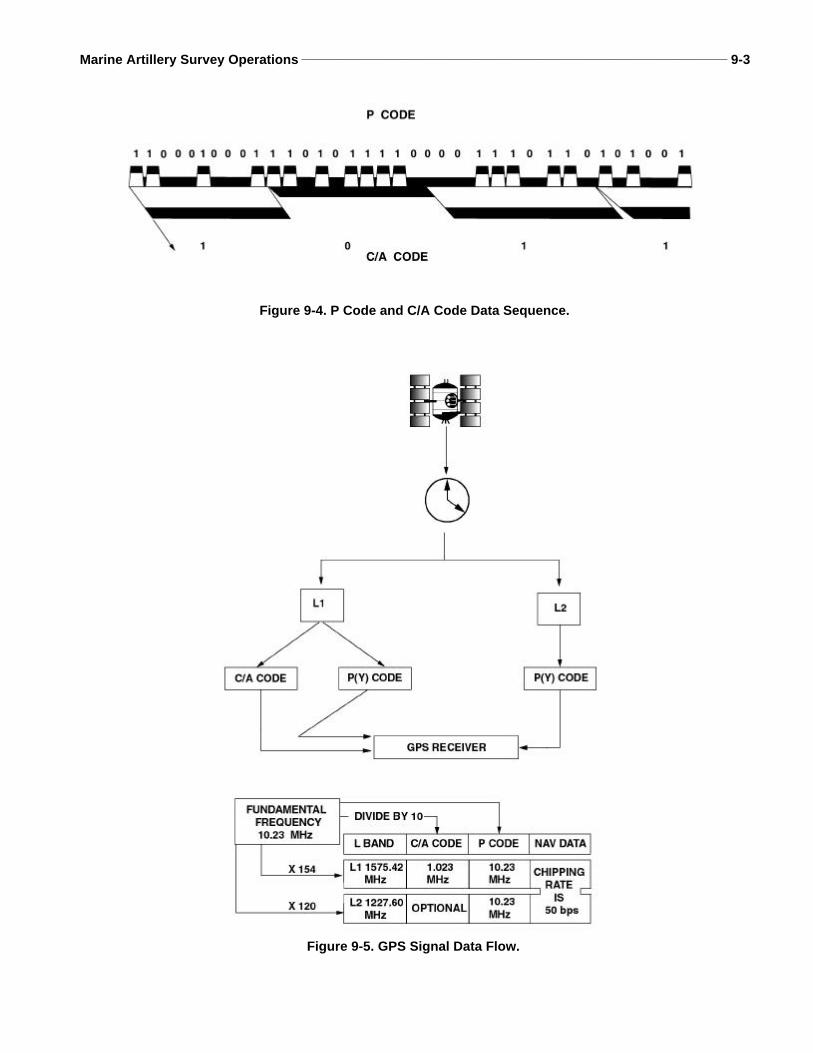
Figure 9-4. P Code and C/A Code Data Sequence.
Figure 9-5. GPS Signal Data Flow.
9-4 ______________________________________________________________________________________________ MCWP 3-16.7
The P code is sometimes referred to as the protectedcode. It is broadcast by all GPS satellites on both the L1and L2 carrier. Transmission of the data sequence iscentered at 1575.42 megahertz on the L1 carrier and at1227.60 megahertz on the L2 carrier. It modulates at±10.23 megahertz on carrier frequencies providing abandwidth of 20.46 megahertz. The P code is a 30-metermeasurement wave and can be encrypted by the satellitecreating a Y code.
The overall P code is a mathematically derived binarysequence that is 267 days (approximately 37 weeks)long. It is broken into 1-week segments for operationaluse. Five of these 1-week segments are reserved forthe GPS control segment. The other 32 segments areavailable for satellite vehicles (SVs). Each SV has aunique 1-week segment code that is a subset of theoverall P code sequence. It is generally accepted thatthe P code repeats every week.
The Nav Data is a 1,500 bit navigation messagebroadcast on both L1 and L2 carriers at a rate of 50bits per second or 50 hertz. The Nav Data containssystem time, clock correction parameters, ionosphericdelay model parameters, and the almanac (ephemerisand health data) on the entire constellation. It isbroadcast once each hour by each GPS satellite andcan be referred to as the D code.
The Nav Data is a separate binary data sequence in thesatellite. But it is modulated over the C/A and P codesfor transmission. Each satellite develops the binarycode sequence of the C/A code, the P code, and theNav Data. Since these sequences are all 1’s and 0’s,the satellite combines the Nav Data with the C/A codeand P code to form two da ta s t reams: one a
combination of the C/A code and the Nav Data, theother a combination of the P code and the Nav Data.These codes are actually transmitted on the carrierfrequencies. The ground receiver then extracts the NavData from the broadcast C/A or P code, whichever itwas receiving.
Ephemeris and Almanac Data
Each GPS satellite transmits almanac data once anhour. The almanac data is the position and healthstatus of all satellites in the constellation. Theephemeris is the position data for each individualsatellite. There are two types of ephemeris data to beconsidered: broadcast and precise.
The broadcast ephemerides are actually predictedsatellite positions transmitted as part of the Nav Data.Ephemerides can be acquired in real time by anyreceiver capable of acquiring the C/A or P codes.Broadcast ephemerides are computed by the mastercontrol station using past tracking data provided fromthe five tracking stations. The new orbital parametersare then transmitted back to the satellites once every 24hours for subsequent transmission to the user segment.
Precise ephemerides are computed from actualtracking data post-processed to obtain more accuratesatellite positions. Precise ephemerides are availablel a t e r and a re more accu ra t e t han b roadcas tephemerides because they are based on actual trackingdata and not predicted data.
SECTION II. SYSTEM SAFEGUARDS, ERROR SOURCES, AND SURVIVABILITY
Selective Availability
When the concept of GPS was initially developed, itwas planned that the P code would be reserved formilitary use, while the less accurate C/A code would beauthorized for use by anyone. During initial system
tes t ing, i t was d iscovered that whi le P codemeasurements provided the expected 10-20 meteraccuracy the C/A code provided accuracy as high as 20meters (much better than the expected 100 meters). TheDOD, expecting much lower accuracy, determined thata method of introducing errors into the satellite signalswas needed to ensure that enemy forces would not be
Marine Artillery Survey Operations ________________________________________________________________________ 9-5
able to obtain high position and timing accuracy fromGPS. Selective availability (SA) was the outcome.
Methods
The DOD uses SA to deny precise position and timingaccuracy to unauthorized users. SA uses two methodsto intentionally introduce errors into the signalstransmitted to the user segment.
The dither method alters or manipulates the satelliteclocks. This method intentionally introduces timingerrors, which ultimately produces position errors at thereceiver because of the importance of accurate time tothe computation of the pseudo-range.
The epsilon method alters the orbital parameters(satellite position) that are broadcast in the Almanacportion of the Nav Data. Position error is then createdbecause the receiver is positioned based on thesatellite location.
Accuracy Levels
The level of accuracy achieved by a GPS receiver nowdepends on if the receiver is equipped with anencryption device that allows the receiver to accept andstore crypto variables referred to as a key. This keyallows the receiver to decrypt SA correction data that istransmitted in the Nav Data message. This key alsoallows the receiver to use the encrypted P code. The twoaccuracy levels are the precise positioning service (PPS)and the standard positioning service (SPS).
The PPS is a precise positioning and timing servicethat is reserved for the US and allied military, as wellas, specific authorized civilian users as long as theirreceiver accepts the crypto key discussed above. Thetechnical specification is listed at 16 meters sphericalerror probable (SEP).
The SPS is the less accurate positioning and timingservice offered to all GPS users. The DOD has statedthat this service will be accurate to 100 meters inhorizontal position and 150 meters vertical, undernormal conditions, 95% of the time. The DOD doeshave the ability to increase the errors created by SAbased upon national security needs.
Antispoofing
Antispoofing (S) is a method used by the DOD toprevent possible hostile imitations of the GPS signal.Encrypting the P code creates the Y code, which canonly be processed by GPS receivers with a valid cryptokey. This encrypted code is very difficult to imitate. It isimportant to understand that the P code and the Y codeare not two separate codes; one is the encrypted versionof the other. A GPS receiver without a valid crypto keycannot process the Y Code and will be limited tomeasurements from the C/A code.
Cryptovariables
As stated before, cryptovariables are necessary for aGPS receiver to access the Precise PositioningService, allowing the receiver to correct for errorscaused by SA and AS. It is unauthorized to use amilitary GPS receiver without a valid crypto fill.
There are three types of key materials available for usewith a GPS receiver: operational, maintenance, andsimulator. There are three formats for key loading: theKOI-18 General Purpose Tape Reader, the KYK-13Electronic Transfer Device (capable of loadingmultiple keys), and the AN/CYZ-10 Data TransferDevice (DTD).
Operational Key Material
Two operational cryptographic keys (group uniquevariable [GUV] key and cryptovariable weekly [CVW]key) are available for issue to a GPS user. Both keys canbe used by a receiver to obtain a daily cryptovariablekey (CVd). All operational keys are classifiedCONFIDENTIAL and are marked CRYPTO.
The GUV key is an annual key. It is a key encryptionkey (KEK) that decrypts previously encrypted dailykeys. A GPS receiver loaded with a GUV key takeslonger to begin processing navigational data than theweekly key because it must first acquire and decryptthe CVd key being broadcast by any GPS satellite.This process could take as long as 12.5 minutes afterinitial GPS signal acquisition. The GUV key is not a
9-6 ______________________________________________________________________________________________ MCWP 3-16.7
years worth of daily keys. It is merely the data neededby the receiver to decrypt the broadcast daily key.
The cryptovariable weekly (CVW) key is sometimesreferred to as the crypto key weekly (CKW). It is a keyproduction key (KPK) that automatically generatesdaily keys within the user equipment. Obtaining thedaily key from a satellite downlink is not necessary forreceivers loaded with a CVW key. A user with a CVWkey starts processing navigational data in less timethan those with a GUV key. Because of this specialcapability, distribution of the CVW key is limited tothose users who demonstrate a valid need for initialGPS acquisition in a minimal amount of time.
The GUV key and the CVW key will produce thesame CVd key. Once the receiver determines thecurrent working CVd, processing navigational datamay commence and the effects of SA and AS can beremoved from the GPS signal and full navigationalaccuracy is restored. A CVd cannot be entered directlyinto the receiver, only a CVW or a GUV key can beentered. The same CVd is used for both SA and AS.
Maintenance Key Material
A maintenance key i s ava i lab le to users fortroubleshooting GPS user equipment. It does not allowa user to gain access to the daily encryption key.Maintenance keys are unclassified and may be reuseduntil they are unusable.
Simulator Key Material
A simulator key is available to users for testingreceivers. The simulator and the equipment must bekeyed with the simulator key. The simulator key doesnot allow a user to gain access to the daily encryptionkey. Simulator keys are unclassified and may bereused until they are physically unusable.
User Equipment Security
Because of the security classification of the CVW andGUV keys, GPS receivers designed specifically formilitary uses are equipped with a special certifiedsecurity module that prevents the extraction ofcryptographic information from the receiver. Thesereceivers can then remain unclassified even whenloaded with a cryptographic key. If classified
information other than crypto is stored in the receiver,the receiver becomes classified at the level of thestored information.
GPS Error Sources
There are many sources of measurement error thatinfluence GPS performance. The sum of all systematicerrors or biases contributing to the measurement erroris referred to as range bias.
The observed GPS range (the range from the satelliteto the receiver) without the removal of biases is calleda pseudo-range. Principal contributors to the finalrange error that also contribute to overall GPS errorare ephemeris error, satellite clock and electronicinaccuracies, tropospheric and ionospheric refraction,atmospheric absorption, receiver noise, and multipatheffects. Other errors include those induced by theDOD (SA and AS). GPS also contains randomobservation errors, such as unexplainable andunpredictable time variation. Due to their randomnature, these errors cannot be modeled and corrected.The following paragraphs discuss these errors as theyassociate with GPS positioning and navigation. Mostare eliminated or their effects significantly reducedwhen GPS is used in a differential mode. (The sameerrors a re common to both rece ivers dur ingsimultaneously observed sessions.)
Ephemeris Errors and Orbit Perturbations
Satellite ephemeris errors are errors in the predictionof the satellite position that are transmitted to the userin the Nav Data. Ephemeris errors are satellite-dependent and very d i f f i cu l t to p red ic t andcompensate. The many forces acting on the predictedorbit of a satellite are difficult to measure directly.
Clock Error
GPS relies heavily on accurate time measurements.GPS satellites carry rubidium and cesium timestandards that are usually accurate to 1 part in 1012 and1 part in 1013, respectively. Most receiver clocks areactuated by a quartz time standard accurate to 1 part in108. The difference between the satellite time and thereceiver time is called the time offset. The product of
Marine Artillery Survey Operations ________________________________________________________________________ 9-7
the time offset and the speed of light equal the possibleerror due to clock bias as—
RE = TOxc
For example, if the time offset is 1 microsecond (10−6) then the RE = 10−6 × 299,792,458 = 299.8 meters.
Ionospheric Delays
GPS signals are electromagnetic signals that aredispersed nonlinearly and refracted when transmittedthrough a highly charged environment, such as theionosphere. Dispersion and refraction of the GPSsignal is referred to as an ionospheric range effect.(The dispersion and refraction of the signal results inan error in the GPS range value.) Ionospheric rangeeffec ts a re f requency dependent . L1 and L2frequencies are affected differently even though theyfollow the same path through the ionosphere.
The error effect of ionospheric refraction on the GPSrange value depends on sunspot activity, time of day,and satellite geometry. Periods of high sunspot activityproduce greater range errors than periods of lowsunspot activity because of the effects of the Sun’sgravity on the ionosphere. Daylight GPS operationswil l produce greater range errors than nightoperations. GPS operations with satellites near thehorizon will have larger range errors than those withsatellites near the zenith. (The signal must passthrough a larger portion of the ionosphere when thesatellite is near the horizon.)
Resolu t ion of ionospher ic re f rac t ion can beaccomplished with the use of a dual frequencyreceiver (L1/L2). During a period of uninterruptedobservation of the L1 and L2 signals, the signals canbe continuously counted and differenced. Theresultant difference reflects the variable effects of theionosphere delay on the GPS signal. Single frequencyreceivers in the absolute and differential positioningmodes normally rely on an ionospheric model that
model the typical ionosphere. Use of these models canremove a significant amount of the ionospheric delay.
Tropospheric Delays
GPS signals are not dispersed by the troposphere butthey are refracted. Tropospheric conditions causingthis refraction can be modeled by measuring the dryand wet components.
The dry component can be modeled easily throughmeasuring the surface pressure using the equation—
Dc = (2.27 × 0.001) × Po
Example: if the surface pressure is 765 millibars then the dry term range error is (2.27 × 0.001) × 765 = 1.73655 or 1.7 meters.
The wet component cannot be so easily modeled. Thewet component is approximated by not only surfaceconditions, but by atmospheric conditions along theentire path of the GPS signal (water vapor content,temperature, altitude, and the angle of the signal pathabove the horizon).
Multipath
Multipath is a positioning error caused by the signalarriving at the receiver from more than one path.Generally, this is due to the receiver being located neara reflective surface such as a metal building orstructure. Newer antenna designs have some filteringcapabilities to reduce the effects of multipath.However , p roper miss ion p lann ing and s i t ereconnaissance is the best way to reduce this type oferror. Averaging of GPS signals over a period can alsoreduce multipath effects.
Receiver Noise
This error source includes a variety of errorsassociated with the receiver’s ability to measure afinite time difference. Errors include signal processingand filtering, clock/signal synchronization and
when RE is the range error due to clock bias.
TO is the time offset.
C is the speed of light (299,792,458 m/s).
when Dc is the dry term range contribution in zenithdirection in meters.
Po is the surface pressure in millibars.
9-8 ______________________________________________________________________________________________ MCWP 3-16.7
correlation methods, receiver resolution, signal noise,and electronic interference. Most errors cannot bemodeled or accounted.
User Equivalent Range Error
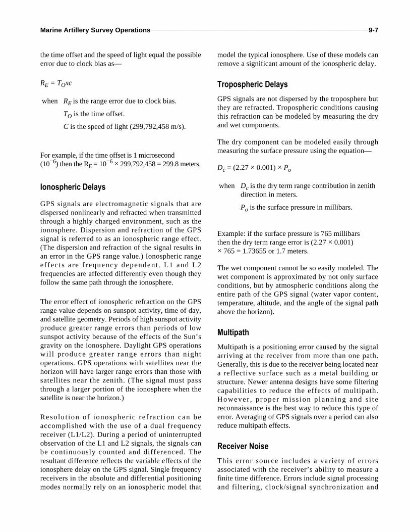
User equivalent range error (UERE) can be referred to asthe total budgeted error caused by the error sources listedabove. Many of these error sources can be reducedthrough planning or using L1 or L2 antennas. Differentialtechniques can even eliminate some of these errorsources. Figure 9-6 lists these errors and biases byassociating them with their source segment. Error valuesin this figure do not include the effects of SA.
Absolute GPS Accuracy
Absolute positions are those that are established withno reference or tie to any other station. They aresometimes referred to as autonomous. For GPSpurposes, this is generally accomplished by use ofcode-phase measurements to determine a pseudo-range. The accuracy of these ranges depends largelyon the code (C/A or P(Y)) being used to determinethe position. This range accuracy (UERE) whencoupled with the geometrical relationships of thesatellites results in a 3-dimensional confidenceellipsoid that depicts uncertainties in all threecoordinates. Since satellites are constantly moving,the geometry constantly changes. GPS accuracy istime/position-dependent.
SegmentSource
ErrorSource
Absolute, C/A code
Pseudo-range, m
Absolute,P(Y) code
Pseudo-range, m
Differential Positioning, m
P(Y) code
Space Clock Stability 3.0 3.0 Negligible
Orbit Perturbations 1.0 1.0 Negligible
Other 0.5 0.5 Negligible
Control Ephemeris Predictions
4.2 4.2 Negligible
Other 0.9 0.9 Negligible
User Ionosphere 3.5 2.3 Negligible
Troposphere 2.0 2.0 Negligible
Receiver Noise 1.5 1.5 1.5
Multipath 1.2 1.2 1.2
Other 0.5 0.5 0.5
I-0 UERE ±12.1 ±6.5 ±2.0
Figure 9-6. User Equivalent Range Error.
Marine Artillery Survey Operations ________________________________________________________________________ 9-9
Root-Mean-Square Error Measures
The two-dimensional (2-D) (horizontal) GPS positionaccuracy is normally estimated using a root meansquare (RMS) radial error statistic called standarddeviation or sigma (σ). A 1-RMS (one sigma) errorequates to the radius of a circle in which the positionhas a 63 percent probability of falling. A circle twicethis radius represents an approximate probability of 97percent. This is a 2-σRMS or 2DRMS (2-deviationsRMS) and is the most commonly used accuracystatistic in GPS survey. In some instances, a 3-σRMS(3DRMS) depicts a circle three times the radius of the1-σcircle. This circle has a 99.7 percent probability.An RMS error statistic represents the radius of a circleand is not listed with a ±.
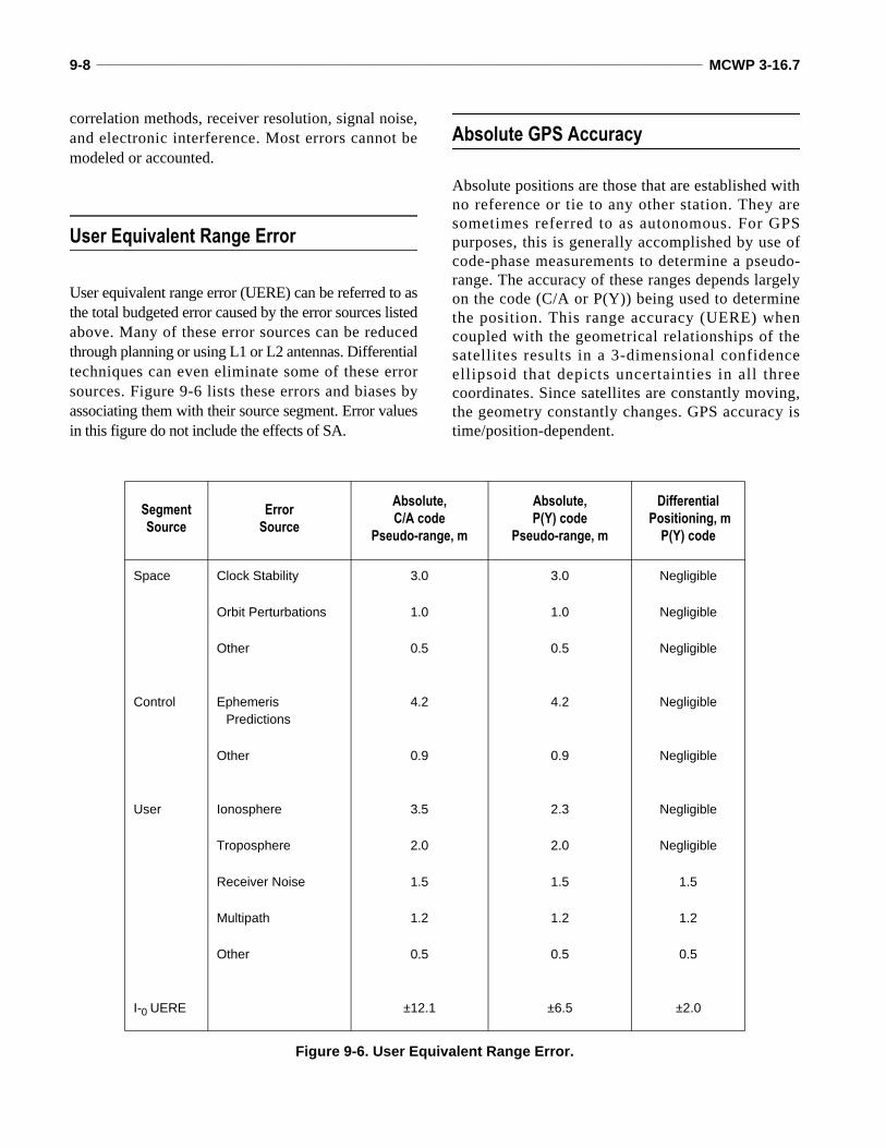
Figure 9-7 depicts RMS on an error ellipse at 2-σ.This ellipse represents a normal distribution of GPSposition errors and is centered at the indicated positionof the receiver. The radii of an error ellipse areexpressed in standard deviation (sigma (σ)) of the
position distribution and usually provide a directionsuch as Sigma North, Sigma East, and Sigma Up. Eachsigma is a probability estimate of how close the actualposition is to the displayed position as discussed.
Probable Error Measures
In 2-D horizontal positioning, a circular error probable(CEP) statistic is most commonly used, especially inmilitary targeting. CEP refers to the radius of a circlewith a 50 percent probability of position confidence. Ameasured or calculated position will fall inside a circleof some radius at least 50 percent of the time.
Three-dimensional (3-D) GPS accuracy is mostcommonly expressed as a spherical error probable(SEP). This value represents the radius of a spherewith a 50 percent confidence level or probability. It isimportant to understand that this sphere onlyapproximates an actual 3-D-error ellipsoid thatrepresents the uncertainties in the geocentriccoordinate system.
Figure 9-7. Error Ellipse at 2-σ RMS.
9-10 _____________________________________________________________________________________________ MCWP 3-16.7
Dilution of Precision
Dilution of precision (DOP) is a scalar quantityrepresenting the contribution or effect of the satellitegeometry to the GPS accuracy. It is the ratio of thes tandard dev ia t ion of one coord ina te to themeasurement accuracy. It could be said that DOP isthe measure of the strength of the satellite geometry.In general, the more satellites that are observed andused in the final solution, the better the solution. SinceDOP can be a measure of geometric strength, it canalso determine the satellites a receiver uses todetermine the most accurate position.
Satellite geometry and DOP can best be visualized bythe following analogy. A rubber ball is suspendedfrom five strings. All five strings are attached at theother end to the ceiling within a couple of meters ofeach other. Because of poor geometry of the strings’attachment to the ceiling, the ball can be moved easily.A large portion of the possible error in the position ofthe ball is due to poor geometry or high DOP. On theother hand, if the ball was still attached to the samestrings but four of the strings were attached to theceiling at the four corners of the room and the fifthstring attached directly above the ball, the ball wouldnot move so easily. This would be due to stronggeometry. The DOP would be small.
The main form of DOP used in measuring absoluteaccuracy is the geometric DOP (GDOP). GDOP is themeasure of accuracy of 3-D position and time. GDOPis related to actual range error by stating that the actualrange error equals the GDOP multiplied by the UERE.
Position dilution of precision (PDOP) is the measureof the accuracy in 3-D position only. PDOP valuesare generally developed from satellite ephemeridesprior to the conduct of survey operations. Thesurveyor can more adequately plan sessions andoccupations for his equipment.
PDOP represents the position recovery at a particularinstance in time and is not representative of the entiresession. PDOP error is generally given in units ofmeters of error per 1-meter error in pseudo-rangemeasurement; i .e . , m/m. If the pseudo-rangemeasurement due to clock errors, atmosphericconditions, etc., is in error by 2 meters and the PDOP is5.5, the possible position error due to satellite geometryis 11 meters. When using pseudo-ranging techniques for
absolute positioning (code phase), PDOP values lowerthan 5 m/m are considered very good; values greaterthan 10 m/m are very poor. For static-type surveys, it isdesirable to make observations during periods ofrapidly changing PDOP.
When the values of PDOP and GDOP are observedover time, high values (> 10 m/m) can be associatedwith poor geometry. The higher the PDOP the poorerthe solution for that instant in time. Poor geometry canbe the result of satellites being in the same plane,orbiting near each other or at similar elevations.
Horizontal di lution of precision (HDOP) is ameasurement of the accuracy in 2-D horizontal position.It is significant in evaluating surveys intended forhorizontal control. Basically, HDOP is the RMSposition error divided by the standard error in the rangemeasurements. It roughly indicates the effects ofsatellite range geometry on a resultant position. HDOPvalues lower than 3 indicate the best geometry.
Ve r t i ca l d i l u t i on o f p r ec i s ion (VDOP) i s ameasurement of the accuracy in standard deviation(σ) in vertical height. Mathematically, it is the σu(Sigma Up) divided by UERE (around 6 meters withP(Y) code and 12 meters with C/A code). A VDOPvalue lower than 3 indicates a strong verticalcomponent in the geometry.
Time dilution of precision (TDOP) is the measurement ofthe accuracy of the time determined by the GPS receiver.
GPS vulnerabilities are generally grouped by thesegment they threaten.
Space Segment
The height of the GPS satellites (10,898 miles) isoutside the range of current antisatellite weapons.Such space weapons would be deployed at loweraltitudes where they could possibly be used againstmore attractive space-based systems. The constellationgenerally keeps the satellites approximately 44,000kilometers apart in each orbital plane. The controlsegment manages the system so that no two satelliteswill orbit within 8,100 kilometers of each other. Thisspatial separation ensures that a single nuclear burst in
Marine Artillery Survey Operations ______________________________________________________________________ 9-11
space at half the closest distance will have little effect,forcing a more direct assault against individualsatellites. A ground-launched attack by antisatteliteswould be detected early enough in the 3-hour flighttime to allow for maneuvering of satellites.
It is unlikely that current or projected technologywould allow a nation to launch a direct attack or evendetonate a nuclear device in the GPS orbit. A nucleardetonation in space would equally affect other space-based systems with a blackout or scintillation effectlasting 10 minutes or longer in the L-band. Detonationwould disturb the atmosphere and the ionosphere withsubsequent effects on propagation. Radiation effectscould incapacitate the functioning of the erasable readonly memories (EROMS) and random accessmemories (RAMS) of these systems if the blast isclose enough. GPS satellites have built-in protectionagainst the electromagnetic pulse (EMP) caused bynuclear detonations and can restore their erasedmemories through the control segment.
Two other factors exist that add an unplanned edge ofsurvivability against antisatellites. The Russian GlobalNavigation Satellite System (GLONASS) orbits at analtitude close to the GPS orbit. A nuclear assaultaga ins t GPS would have the same ef fec t onGLONASS. The increased use of GPS by formerEastern Bloc nations including the former SovietUnion is also an unplanned edge.
Since the introduction of the Strategic Defense Initiative(SDI), lasers have become a planned vulnerability toorbiting satellites. Survivability of GPS against lasertechnology is enhanced by limited laser hardening ofthe satellites. A space-based laser at low altitudes wouldbe an extremely heavy device to launch. Tracking andtargeting of a GPS satellite is extremely difficult due toits relatively small size and its orbital rate (14,500kilometers per hour). Technology is available for ahigh-power ground-based laser-to-target and has alimited effect on GPS satellites.
Should there be a loss of any GPS sa te l l i te ,replenishment from the ground can be accomplishedwithin 2 months. The system can operate fully evenwith the loss of 9 or more satellites, still providing 3-Dcoverage for 12 hours and 2-D coverage for more than20 hours.
Control Segment
This segment is considered by many to be the mostvulnerable GPS segment. The master control station(Colorado Springs) is very well protected by beingcollocated with several military bases. The trackingstations do not have this protection. All stations aresusceptible to espionage and natural disasters, buttracking stations are much more vulnerable to nuclearand conventional assaults. These factors have beenconsidered, and although the ability exists to exertcomplete control over the satellites from the mastercontrol station, the uplink to each satellite will be lessfrequent than the current 8 hours. Next-generationsatellites are planned to provide a cross-link rangingcapability that will allow satellites to communicate witheach other, making offshore tracking stations redundant.Jamming the control segment between the trackingstations and the master control station is a real possibility.
User Segment
Only two major vulnerabilities exist with the users e g m e n t : c r y p t o g r a p h i c k e y s e c u r i t y a n djamming. Several types of jamming can be usedagainst GPS receivers.
Cryptographic Key Security
Should the enemy capture a GPS receiver with a validcrypto fill, the PPS-security module prevents reverseengineering so that the enemy cannot gain access tothe cryptographic data stored inside the receiver. Also,the regular change of crypto keys adds to the securityand survivability of the system.
Spoofing
Spoofing is classified as the enemy’s attempts toduplicate or imitate GPS signals. Spoofing requiresthat the enemy have a knowledge of the receivedsatellite phase and frequency at the targeted receiverantenna. The proper carrier frequency and timing codephase plus a sufficiently higher power output willallow a deceptive jammer to establish a false lock withthe receiver. The enemy must know which satellites
9-12 _____________________________________________________________________________________________ MCWP 3-16.7
are being tracked and the position and velocity of thereceiver to create a false signal with the correctDoppler shift. Once false lock is established, thespoofer can perturb the duplicated navigation signalsto cause navigation errors.
When GPS antispoofing protection is enabled, spooferscannot autonomously generate the signals needed todeceive the receiver that is looking for the encrypted Pcode. This technique transforms the P code bycryptographic means. The resultant bit stream is acypher text called the Y code that replaces the P code inits entirety. Receivers with a valid crypto key willencrypt their own generated P code to produce a Y codeinside the receiver needed for correlation with thesatellites transmitted Y code. The C/A code is totallyunaffected by the P code encryption. This is why the C/A code is very susceptible to deception jamming.
Continuous Wave Jamming
A continuous wave (CW) jammer (or spot jammer)concentrates its jamming power in a very narrow bandaround the L1 or L2 carrier. In the GPS receiver thejamming power spreads out according to the receiverprocessing gain using the modulated C/A or P code.After spreading, only a small portion of the jammingpower enters the tracking loops of the receiver.Consequently, a CW (spot) jammer needs to be verypowerful to effectively jam a GPS receiver.
Wide Band Jamming
A wide band jammer needs a sufficiently wide spectrumto cover the frequency band of the GPS signals.Usually, wide band jamming is performed in either asweeping mode or a quasi-random noise (barrage)mode. In a sweeping mode the jammer carrier movesrapidly and possibly randomly through the band to bejammed. In barrage jamming the spectral power densityis low compared to spot jamming.
Pulse and Amplitude Modulated Jamming
A pulse jammer switches its power on and off duringan operation cycle. The modulation rate can be chosenas needed (pulse repetition frequency and pulseduration). An amplitude modulated jammer varies itspower linearly; modulation depth and frequency canbe chosen as needed. Besides jamming effects already
described, this type of jamming could have a negativeimpact on the GPS receiver by disturbing the internaloperating cycles of the receiver processor unit or theelectronics of the antenna.
Jamming Effects on Code Acquisition
The GPS user is at a severe disadvantage when havingto use C/A code acquisition in a hostile region. Currenttechnology receivers have a limited tolerance tojamming during C/A code acquisition (usually around25 decibels). Although only 1,023 chips must besearched in the C/A code, a large frequency windowmust be searched to account for satellite and receiverDoppler shift. The receiver must maintain a largepredetection bandwidth to acquire the C/A code at theexpense of reduced jamming tolerance (J/S). The C/Acode is widely disseminated. A smart jammer canbroadcast a false signal and lock up the receiver withvery low power. Tests indicate that a very modest 1-watt noise jammer prevents a receiver from acquiringthe GPS signal using the C/A code out to 85kilometers. If the jammer were to transmit a spoofingsignal, the receiver would not be able to discriminatebetween the desired GPS signal and the spoofingsignal. The receiver’s jamming tolerance would be onthe order of 0 decibels, a 1-watt spoofer could deny C/A code acquisition past 1,000 kilometers or to thejammer’s horizon.
The P(Y) code is virtually impossible for an adversaryto spoof because of its long length and the encryptionof the P code into the Y code. Also, the P(Y) code has10 decibel more antijam protection than the C/A codebecause of its 10 times larger bandwidth. Some currenttechnology receivers us ing direct P(Y) codeacquisition (hot start) can tolerate a J/S level in excessof 35 decibels. However, because the P(Y) code is solong, (6 × 10¹² chips) much time or more correlatorsoperat ing in paral lel are needed for the two-dimensional search over code timing and Dopplerfrequency. Thus, up to date satellite ephemerides andaccurate code timing must be available to effectivelyperform a hot start.
Reacquisition typically has very accurate initial codetiming. If this accuracy is available during direct P(Y)code acquisition, the reacquisition problem is the sameas the acquisition problem with increased J/S tolerance(in excess of 50 decibels depending on the receiver).
Marine Artillery Survey Operations ______________________________________________________________________ 9-13
Antijam Capabilities of GPS
GPS vulnerability to jamming can never be completelyeliminated. With constantly improving techniques andtechnology, higher power outputs by the enemyjammers is required to deny access to GPS signals.
The GPS satellites broadcast in the ultra-highfrequency (UHF) domain. UHF signals cannot “goaround” obstacles such as buildings, hilltops, largerocks, etc. the way low domain frequencies can. Forthis reason, ground based jammers are restricted bysevere line-of-sight limitations. Air or space-bornejammers, obviously, are not so restricted. A smart userwill position his GPS receiver to limit the effects of aline-of-sight jammer. Defilade areas that still allowopen skies for satellite signals can be used. Handheldreceivers can be placed in a “cat hole” or the user cansimply turn his back to the suspected direction of thejammer. Once the receiver has a lock on the P(Y)code, the user should be able to operate normally inmost jamming environments.
The satellite signal is a continuous wave type signal. Thissignal is spread by modulation and enters the receiverwith the jamming signal. The original signal is recoveredas the jammer energy is spread over the modulation andmost of the jammer power is filtered out.
To locate, track, and demodulate a satellite signal, thereceiver requires a certain minimum ratio betweenreceived signal power and the noise power. This value(or threshold) is referred to as the signal-to-noise ratio
(SNR). The noise power is dissipated over a widebandwidth, while the satellite signal power isconcentrated in a very narrow frequency band. Usingfilters, the GPS receiver narrows its bandwidth to theabsolute minimum in order to receive the maximumsignal power and minimum noise. A receiver canusually recognize the jammer power as noise;therefore, much of its effects are filtered out.Depending n the power output of the jammer, the SNRmay be too high for the receiver to filter out enoughnoise to determine data.
Many other antijam capabilities exist for GPS. Amongthem is the iner t ia l navigat ion system (INS)integration with GPS and high cost antennas. Both areused in military applications but generally withmissile, rocket, and aircraft navigation technologies.For the most part, antijam capabilities for Marineground units will be enhanced by proper planning andpositioning of GPS assets.
The surveyor must be aware of the ambient conditionsof the GPS sa te l l i t e s and the i r su r round ingenvironment. Solar flares, occurring in 11-year cycles,send great fountains of electromagnetic energy andradiation deep into space, causing interferences inGPS signals. Meteor showers, such as the Lenoidevent, occur close to the Earth, and could potentiallydamage satellites in the GPS constellation. GPSsatellites are hardened against such possibilities, butare not invulnerable.
SECTION III. GPS MEASUREMENTS
GPS Reference System
The GPS satellites reference their own position to theWGS 84 coordinate system. This system is based on theWGS 84 ellipsoid. To fix the Earth in time and space forthe development of the WGS 84 ellipsoid, theConventional Terrestrial Pole of 1984 (CTP 84) waschosen. The position of the Earth’s polar axis at 1984.0as defined by the Bureau International De l’Heure(BIH) is used to define the z-axis of the WGS 84cartesian coordinate system. The x- and y-axes are then
referenced to that z-axis. All positions determined byGPS are originally in this format, WGS 84 cartesian.Receivers and software applications for GPS have thecapability to provide positions in other coordinatesystems and other datum/ellipsoid references.
Code Phase Measurements
The primary purpose of code phase measurements is todetermine approximate ranges from satellites to the
9-14 _____________________________________________________________________________________________ MCWP 3-16.7
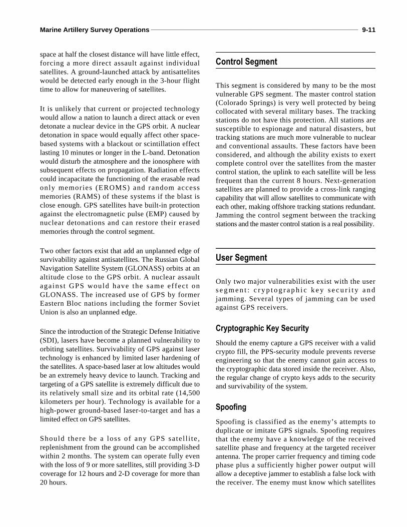
GPS receiver that allow the receiver to determine itsposition. Since this position is not referenced or relativeto any other position or receiver, it is referred to as anabsolute position. Clock biases, atmospheric absorptionand refraction, and other inherent errors makedetermination of a true range virtually impossible. Theactual range determined by the GPS receiver is referredto as a pseudo-range. See figure 9-8.
Pseudo-random Noise Code
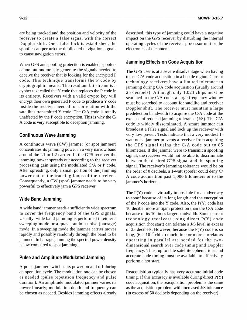
The Pseudo-random noise (PRN) code is a binary datastring of digital ones and zeros that is unique to thesatellite broadcasting it. This code is used by thereceiver to identify the satellite it is tracking. Thiscode is repeated every millisecond (C/A) and everyweek (P/Y). See figure 9-9.
Time Delay
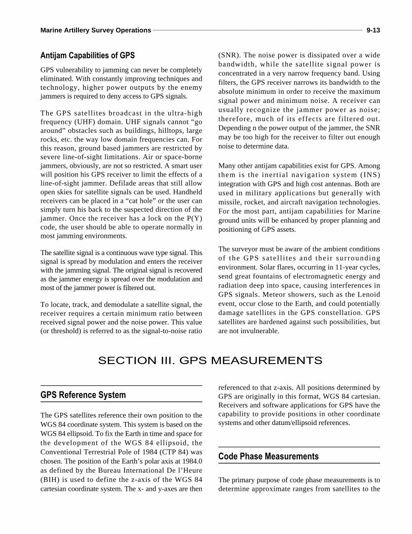
Before the receiver can compute the pseudo-range tothe satellite, it must determine the time required for thesignal to travel from the satellite to the antenna. Thereceiver stores a replica of each satellite’s PRN code.When the receiver detects a satellite signal, itidentifies the satellite by its PRN that has beenreplicated from memory. The code received from thesatellite is then compared to the replicated code. Thereceiver slides the replicated code in time until it linesup with the satellite’s transmitted code. The amount oftime that was needed to slide the code is the time delayof the transmission or travel time. See figure 9-10.
Figure 9-8. Pseudo-range.
Figure 9-9. Carrier Modulated by PRN.
Figure 9-10. Time Delay of a GPS Signal.
Marine Artillery Survey Operations ______________________________________________________________________ 9-15
Satellite Ranging
The only measurement made by a code-phase receiveris the time delay or transmission time. Radio wavestravel at the speed of light. This constant value isstored in the memory of the GPS receivers. Areceiver capable of making code-phase measurementswill compute the pseudo-range using the formulapseudo-range = ∆t × speed of light.
This procedure can be simultaneously performed onmany satellites. The number of satellites depends onthe receiver used, or more specifically, how manychannels are available in the receiver.
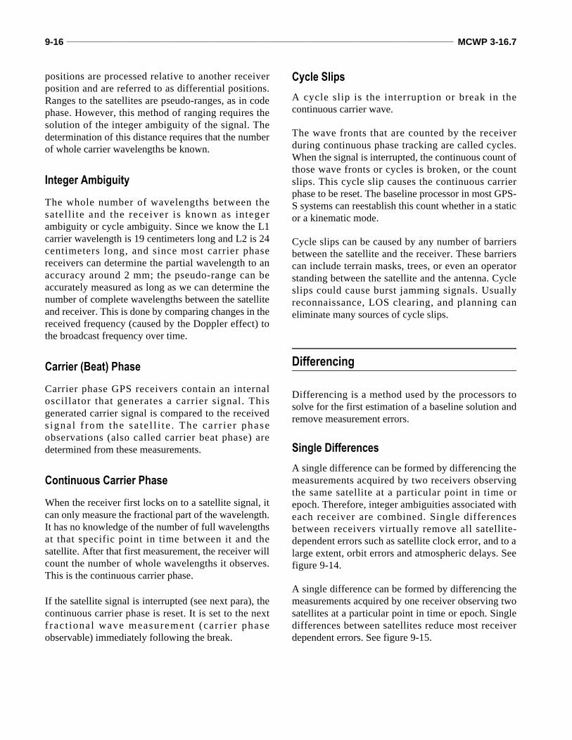
Once a satellite is tracked and the receiver determinesa pseudo-range, the receiver basically knows it islocated on a sphere whose radius equals the pseudo-range with the satellite at the center of the sphere. Seefigure 9-11.
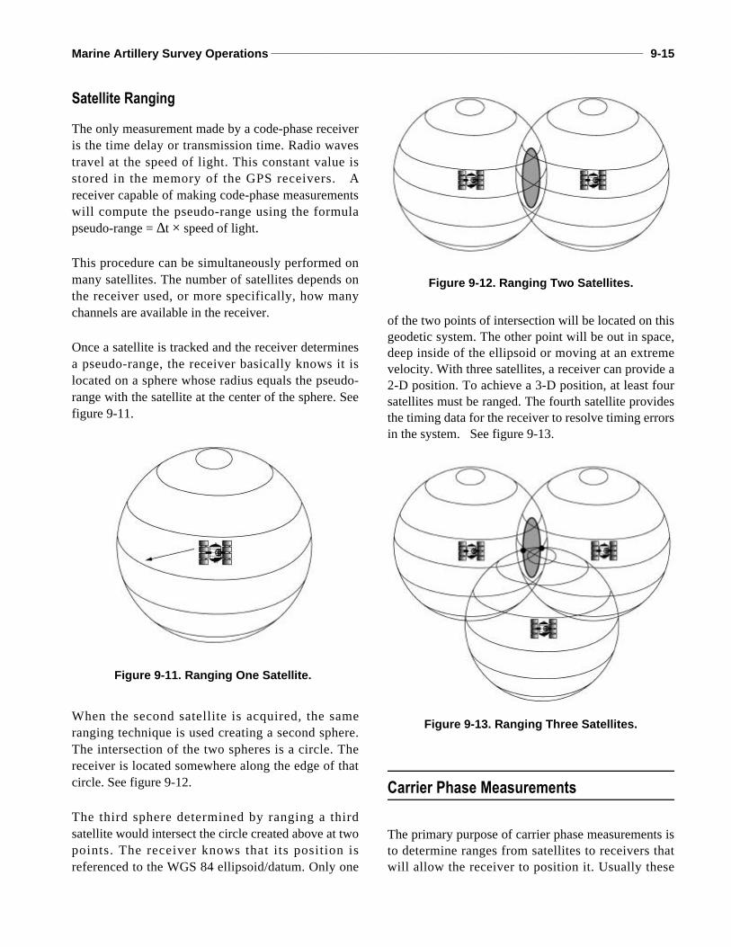
When the second satellite is acquired, the sameranging technique is used creating a second sphere.The intersection of the two spheres is a circle. Thereceiver is located somewhere along the edge of thatcircle. See figure 9-12.
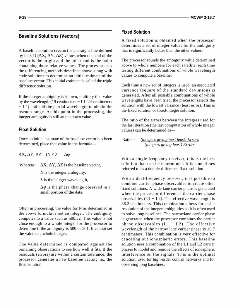
The third sphere determined by ranging a thirdsatellite would intersect the circle created above at twopoints. The receiver knows that its position isreferenced to the WGS 84 ellipsoid/datum. Only one
of the two points of intersection will be located on thisgeodetic system. The other point will be out in space,deep inside of the ellipsoid or moving at an extremevelocity. With three satellites, a receiver can provide a2-D position. To achieve a 3-D position, at least foursatellites must be ranged. The fourth satellite providesthe timing data for the receiver to resolve timing errorsin the system. See figure 9-13.
Carrier Phase Measurements
The primary purpose of carrier phase measurements isto determine ranges from satellites to receivers thatwill allow the receiver to position it. Usually these
Figure 9-11. Ranging One Satellite.
Figure 9-12. Ranging Two Satellites.
Figure 9-13. Ranging Three Satellites.
9-16 _____________________________________________________________________________________________ MCWP 3-16.7
positions are processed relative to another receiverposition and are referred to as differential positions.Ranges to the satellites are pseudo-ranges, as in codephase. However, this method of ranging requires thesolution of the integer ambiguity of the signal. Thedetermination of this distance requires that the numberof whole carrier wavelengths be known.
Integer Ambiguity
The whole number of wavelengths between thesatell i te and the receiver is known as integerambiguity or cycle ambiguity. Since we know the L1carrier wavelength is 19 centimeters long and L2 is 24centimeters long, and since most carrier phasereceivers can determine the partial wavelength to anaccuracy around 2 mm; the pseudo-range can beaccurately measured as long as we can determine thenumber of complete wavelengths between the satelliteand receiver. This is done by comparing changes in thereceived frequency (caused by the Doppler effect) tothe broadcast frequency over time.
Carrier (Beat) Phase
Carrier phase GPS receivers contain an internaloscillator that generates a carrier signal. Thisgenerated carrier signal is compared to the receiveds igna l f rom the sa te l l i t e . The ca r r i e r phaseobservations (also called carrier beat phase) aredetermined from these measurements.
Continuous Carrier Phase
When the receiver first locks on to a satellite signal, itcan only measure the fractional part of the wavelength.It has no knowledge of the number of full wavelengthsat that specific point in time between it and thesatellite. After that first measurement, the receiver willcount the number of whole wavelengths it observes.This is the continuous carrier phase.
If the satellite signal is interrupted (see next para), thecontinuous carrier phase is reset. It is set to the nextf rac t ional wave measurement (car r ie r phaseobservable) immediately following the break.
Cycle Slips
A cycle slip is the interruption or break in thecontinuous carrier wave.
The wave fronts that are counted by the receiverduring continuous phase tracking are called cycles.When the signal is interrupted, the continuous count ofthose wave fronts or cycles is broken, or the countslips. This cycle slip causes the continuous carrierphase to be reset. The baseline processor in most GPS-S systems can reestablish this count whether in a staticor a kinematic mode.
Cycle slips can be caused by any number of barriersbetween the satellite and the receiver. These barrierscan include terrain masks, trees, or even an operatorstanding between the satellite and the antenna. Cycleslips could cause burst jamming signals. Usuallyreconnaissance, LOS clearing, and planning caneliminate many sources of cycle slips.
Differencing
Differencing is a method used by the processors tosolve for the first estimation of a baseline solution andremove measurement errors.
Single Differences
A single difference can be formed by differencing themeasurements acquired by two receivers observingthe same satellite at a particular point in time orepoch. Therefore, integer ambiguities associated witheach receiver are combined. Single differencesbetween receivers virtually remove all satellite-dependent errors such as satellite clock error, and to alarge extent, orbit errors and atmospheric delays. Seefigure 9-14.
A single difference can be formed by differencing themeasurements acquired by one receiver observing twosatellites at a particular point in time or epoch. Singledifferences between satellites reduce most receiverdependent errors. See figure 9-15.

Marine Artillery Survey Operations ______________________________________________________________________ 9-17
Double Differences between Satellites and Receivers
A double difference is formed by differencing twosingle differences. This involves two receiversobserving the same two satellites at the same epoch.Four separate measurements and four separate integerambiguities are combined to create a difference. Thedouble differencing mode removes most of the effectsof satellite and receiver clock drift. See figure 9-16.
Triple Differences between Satellites, Receivers, and Time
A triple difference is determined by combining twodouble differences over time. The double differencedetermined by a set of satellites and receivers at aparticular epoch is combined with the doubledifference form the same satellites and receivers at adifferent epoch. In this mode, integer ambiguitiescancel out of the computations because it does notchange over time.
Triple differences are often used to find cycle slips. Acycle slip, in the single differencing mode, causes thereceiver to recompute the combined integer; thereforeafter a cycle slip, the integer ambiguity does change. Alarge change in the triple difference is a good indicatorof a cycle slip at that epoch. See figure 9-17.
Figure 9-14. Single Differencesbetween Receivers.
Figure 9-15. Single Differences between Satellites.
Figure 9-16. Double Differencing.
Figure 9-17. Triple Differencing.
9-18 _____________________________________________________________________________________________ MCWP 3-16.7
Baseline Solutions (Vectors)
A baseline solution (vector) is a straight line definedby its 3-D (∆Χ, ∆Υ, ∆Ζ) values when one end of thevector is the origin and the other end is the pointcontaining those relative values. The processor usesthe differencing methods described above along withcode solutions to determine an initial estimate of thebaseline vector. This initial estimate is called the tripledifference solution.
If the integer ambiguity is known, multiply that valueby the wavelength (19 centimeters − L1, 24 centimeters− L2) and add the partial wavelength to obtain thepseudo-range. At this point in the processing, theinteger ambiguity is still an unknown value.
Float Solution
Once an initial estimate of the baseline vector has beendetermined, place that value in the formula—
∆Χ, ∆Υ, ∆Ζ = (N × λ) + ∆φ
Often in processing, the value for N as determined inthe above formula is not an integer. The ambiguitycomputes to a value such as 500.52. This value is notclose enough to a whole integer for the processor todetermine if the ambiguity is 500 or 501. It cannot setthe value to a whole integer.
The value determined is compared against theremaining observations to see how well it fits. If theresiduals (errors) are within a certain tolerance, theprocessor generates a new baseline vector; i.e., thefloat solution.
Fixed Solution
A fixed solution is obtained when the processordetermines a set of integer values for the ambiguitythat is significantly better than the other values.
The processor rounds the ambiguity value determinedabove to whole numbers for each satellite, each timetesting different combinations of whole wavelengthvalues to compute a baseline.
Each time a new set of integers is used, an associatedvariance (square of the standard deviation) isgenerated. After all possible combinations of wholewavelengths have been tried, the processor selects thesolution with the lowest variance (least error). This isthe fixed solution or fixed-integer solution.
The ratio of the errors between the integers used forthe last iteration (the last computation of whole integervalues) can be determined as—
With a single frequency receiver, this is the bestsolution that can be determined. It is sometimesreferred to as a double-difference fixed solution.
With a dual-frequency receiver, it is possible tocombine carrier phase observables to create otherfixed solutions. A wide lane carrier phase is generatedwhen the processor differences the carrier phaseobservables (L1 − L2). The effective wavelength is86.2 centimeters. This combination allows for easierresolution of the integer ambiguities so it is often usedto solve long baselines. The narrowlane carrier phaseis generated when the processor combines the carrierphase observables (L1 + L2) . The e f fec t ivewavelength of the narrow lane carrier phase is 10.7centimeters. This combination is very effective forcanceling out ionospheric errors. This baselinesolution uses a combination of the L1 and L2 carrierphases to model and remove the effects of ionosphericinterference on the signals. This is the optimalsolution, used for high-order control networks and forobserving long baselines.
Whereas: ∆Χ, ∆Υ, ∆Ζ is the baseline vector,
N is the integer ambiguity,
λ is the integer wavelength,
∆φ is the phase change observed in asmall portion of the data.
Ratio = (integers giving next least) Errors(integers giving least) Errors
Marine Artillery Survey Operations ______________________________________________________________________ 9-19
SECTION IV. GPS SURVEY METHODS AND TECHNIQUES
Absolute Positioning
Absolute positioning is a GPS survey method thatinvolves using a single passive receiver; e.g., AN/PSN-11 PLGR, AN/PSN-13 MSGR 4000. The termabsolute does not refer to a specific accuracy. It meansthis method does not rely on any source of informationother than what is collected by the receiver at thatstation. This position is not relative (common) to anyother station. The accuracy of this position depends onmany different error sources as well as the user’s levelof authorization (PPS or SPS).
The receiver collects data from multiple satellites anduses this data to determine position, velocity, andtiming information. The position is generallydetermined from code phase measurements. Somereceivers can use carrier phase measurements todetermine absolute positions.
Differential (Relative) Positioning
Differential positioning requires at least two receiverscollect data from at least four common satellitessimultaneously to compute a vector between them.The vector is then fixed at one end to a point and theother end is the relative position.
Usually, one receiver is located at a known point.Depending on the differential technique used, morethan four common satellites may be necessary.Processing the collected data can be performed in theoffice or by the receiver in the field, also depending onthe differential technique used.
Much of the accuracy achieved from this method isdue to the use of common satellites and commonepochs (a specific point of time selected for a GPSmeasurement). Figure 9-16 shows that differentialtechniques negate most sources of error. This isbecause the same error exists at each station collectingdata from a specific satellite at a specific epoch. The
errors broadcast by satellite PRN23 and collected byreceiver A at epoch 1 are the same errors collected byreceiver B at epoch 1. The errors broadcast from thesatellites have no effect on the dimensions of thevector because the errors are equal at each end.
This is actually only true for errors sources in theSpace and Control segments. User segment errorsources are not always equal at each end of the vector.For distances under 25-30 kilometers, the troposphericand ionospheric errors are basically the same. Signalsfrom satellite PRN23 to receiver A travel through thesame sampling of the atmosphere as the signals fromPRN23 to receiver B. Larger distances may add somesmall errors into these measurements. An L1/L2antenna will decrease this error.
Code Phase Differential Positioning
Determining differential positions from code phasemeasurements is performed by applying a correctionto the pseudo-range determined from an individualsatellite to the receiver.
This process begins with the pseudo-ranges from codephase measurements used to determine the absolutepositions of the receivers. Since the errors collected ateach receiver are the same for each epoch, a pseudo-range correction (PRC) can be computed. In otherwords, assume we know the exact position of asatellite at a specific epoch and the surveyed positionof a GPS receiver, we can determine a true range. Ifthe measured pseudo-range is 79 meters and the truerange is 81 meters, the PRC is +2 meters. A pseudo-range correction can be generated for each satellitebeing observed. Any receiver that is simultaneouslycollecting data from at least four common satellitescan apply the PRC to its pseudo-range measurementsto obtain a relative (common) position; thus thedistance between the two points will be relativelyaccurate (0.5-10 meters) even when the absolutepositions are not.
Code phase differential positioning has its primaryapplications in real-time navigation where relativeaccuracy is as low as 10 meters are acceptable. Also,
9-20 _____________________________________________________________________________________________ MCWP 3-16.7
some engineering survey applications can tolerate thisaccuracy. This would not be acceptable for geodeticapplications, and does not meet artillery specifications.
Carrier Phase Differential Positioning
Determining differential positions from carriermeasurement is as simple as fixing an end of ameasured vector to determine the position of the otherend. Through processing, other vectors can then befixed to the end of the first vector to create a network.Kinematic and static surveys are both usuallyperformed using carrier phase differential positioning.
Static and Kinematic Techniques
When GPS receivers are used for surveying purposes,it is generally accepted that the survey will beperformed using carrier phase differential (relative)survey methods. Differential survey is usually dividedinto two techniques: static and kinematic.
Static surveys provide the most accurate results.Receivers must remain stationary (static) for a period oftime depending on the type of static survey performed.There are two types of static survey: static and faststatic. Both require extensive planning and post-processing. Static survey allows for extremely accuratenetworking of survey control. Due to planning, fieldwork, and post-processing requirements, this techniqueshould only be used by surveyors whose mission is toprovide fourth order control.
Kinematic surveys provide accuracy results sufficientfor most artillery survey missions (fourth and fifthorder) but does not provide the same networkingcapabilities as static techniques. There are two types ofkinematic surveys: stop-and-go and continuous. Stop-and-go surveys can be post-processed in the officecomputers or in the field by the receivers using RTKand RTK/OTF procedures. Kinematic surveytechniques require that one receiver remains staticwhile another acts as a rover, moving along a route orfrom station to station collecting data.