Embed Size (px)
Citation preview
9999----1111
AMERICAN RAILWAY ENGINEERING AND MAINTENANCE OF WAY ASSOCIATION Practical Guide To Railway Engineering
Railway Electrification
Chapter
©2003 AREMA®
9999----2222
A R E M A C O M M I T T E E 2 4 - E D U C A T I O N & T R A I N I N G
Railway Electrification
Andrew J. Gillespie P.E.
LTK Engineering Services Denver, CO [email protected]
H. Ian Hayes P.E.
LTK Engineering Services Denver, CO [email protected]
©2003 AREMA®
C H A P T E R 9 � R A I L W A Y E L E C T R I F I C A T I O N
9999----3333
RAILWAY ELECTRIFICATION
9.1 Introduction espite the competition of airplanes, buses, trucks and cars, trains
still play a major transportation role in society, filling specific markets such as high-speed and non-high-speed intercity passenger service, heavy haul of minerals and freight, urban light rail systems and commuter rail.
This chapter presents an introduction to electrification of rail systems. It is intended to provide a historical perspective and an overview of typical design principles, construction practice and maintenance considerations. Those interested in learning more are invited to review AREMA�s Manual for Railway Engineering, Chapter 33, Electrical Energy Utilization, and Chapter 17, High Speed Rail Systems, which contain sections devoted to electrification power supplies, traction power systems studies and guidelines for the design of overhead contact systems.
9.2 Development of Motive Power for Railways The earliest recorded tramway served a mine in Germany, beginning in about 1550. The tramway was developed because the rolling resistance of wheels on rails was much less than on the roads of the time. This allowed heavier loads to be pulled for the same
Chapter
D
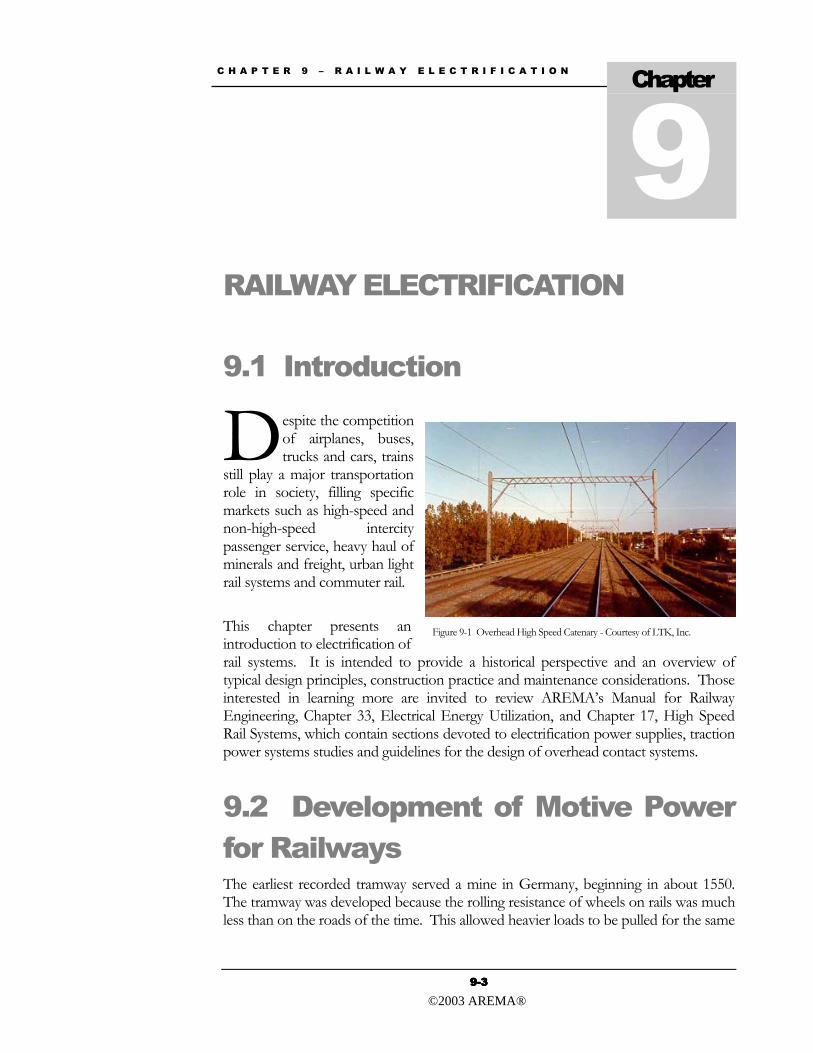
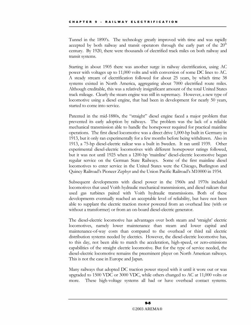
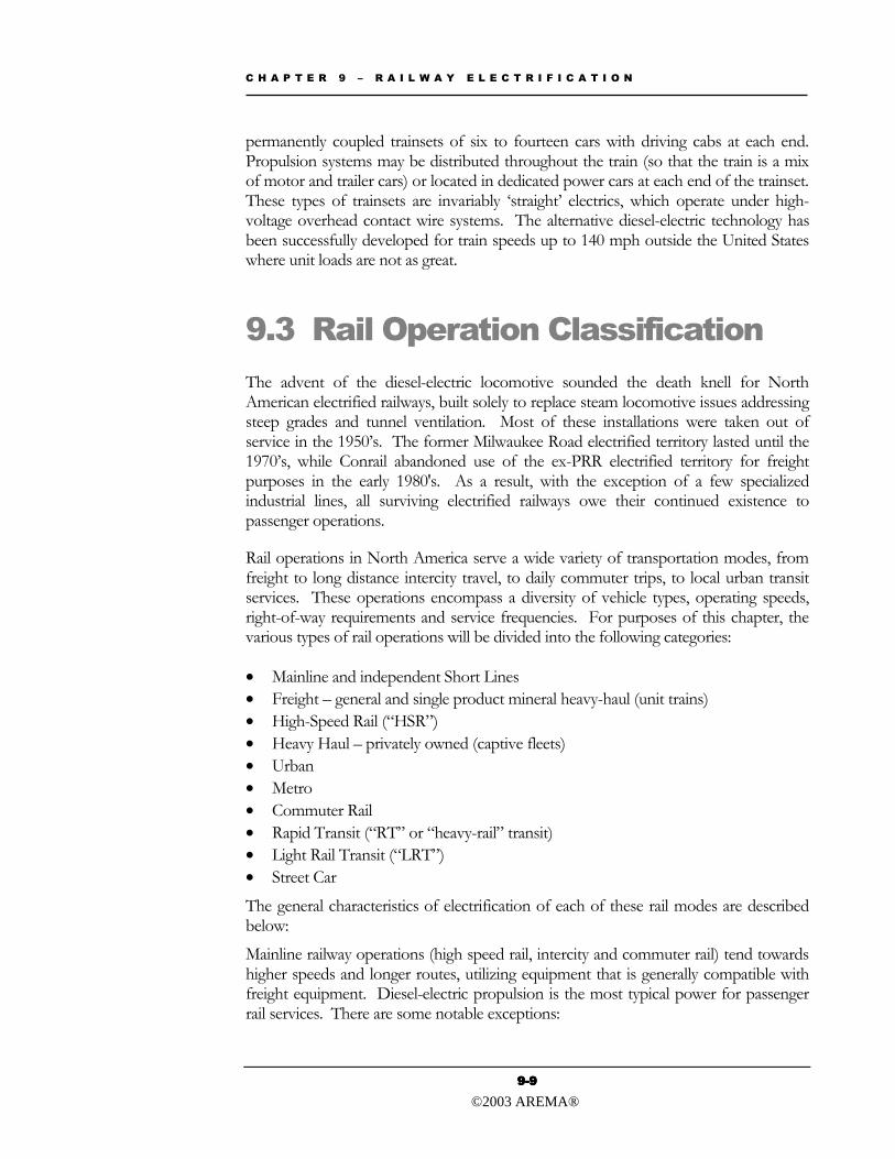
Figure 9-1 Overhead High Speed Catenary - Courtesy of LTK, Inc.
©2003 AREMA®
C H A P T E R 9 � R A I L W A Y E L E C T R I F I C A T I O N
9999----4444
power. Horses did the work, and it was not until the steam engine was developed, first as a stationary engine and then in the early 1800's as a locomotive, that the horse began to be replaced. Surprisingly, this transition took another 100 years, with the last horse-tramways being phased out by retrofitting electric traction equipment into tramcars and streetcars in the early 1900's.
In both North America and Europe, the period from 1800 to 1900 was truly a developmental age for railways. From its beginning in the 1800�s, steam traction expanded without serious competition. Locomotives became larger, faster and more powerful for the next 125 years, culminating with massive machines weighing over 500 tons and capable of speed of 120 mph. However, the problem with all steam engines, irrespective of the fuel that was used (wood, coal and later oil), is the smoke, coupled with high maintenance costs, the frequent fueling and the need for large quantities of water. These problems led to the eventual demise of the steam locomotive.
In the late 19th century, some early steam power was replaced by electric traction equipment that had finally become commercially viable through the early efforts of Werner von Siemens, Thomas Edison and others. First using batteries, but later using stationary electric generators, electric streetcars demonstrated the practicality of electric traction. Based on these demonstrations, mainline railways, which up until that time were 100% reliant on steam traction, began taking an interest in electric traction. In the period 1895 to 1900, several sections of mainline track were electrified at various voltages from 550 volts DC to 660 volts DC. The slow development of electric traction resulted partly from the lack of available utility power. This situation began to be rectified when the demand for electric lighting drove a need for a public electricity supply, necessitating the development of sizeable electricity generation plants.
Compared to steam power, electric propulsion offered higher performance and avoided smoke problems. Railways readily accepted electric propulsion on steep grades and long tunnel territories, where significant advantage was obtained. With respect to railway passenger operations, eastern railway trunk lines established extensive electric commuter rail systems, some with long-distance intercity services as well. Certain western trunk lines operated intercity passenger services over electrified territory, built primarily to conquer grades and long, difficult-to-ventilate tunnels. In the Midwest, a demonstration electric traction line was built to shuttle visitors to the Colombian World Exposition in Chicago in 1893. This was followed by the operation of numerous electric trolley lines within Chicago by the turn of the century. It was not until 1926, that the first Illinois Central commuter trains (predecessor of Metra Electric) began electric operation.
Throughout North America, passenger rail systems began to adopt traction electrification systems in the late 19th century. The first successful and sustained use of electric traction in transit revenue service occurred with Frank Julian Sprague�s streetcar line in Richmond, VA in 1888. The first application of electricity to mainline railway operations was the Baltimore & Ohio�s electrification of Baltimore�s Howard Street
©2003 AREMA®
C H A P T E R 9 � R A I L W A Y E L E C T R I F I C A T I O N
9999----5555
Tunnel in the 1890�s. The technology greatly improved with time and was rapidly accepted by both railway and transit operators through the early part of the 20th century. By 1920, there were thousands of electrified track miles on both railway and transit systems.
Starting in about 1905 there was another surge in railway electrification, using AC power with voltages up to 11,000 volts and with conversion of some DC lines to AC. A steady stream of electrification followed for about 25 years, by which time 38 systems existed in North America, aggregating about 7000 electrified route miles. Although creditable, this was a relatively insignificant amount of the total United States track mileage. Clearly the steam engine was still in supremacy. However, a new type of locomotive using a diesel engine, that had been in development for nearly 50 years, started to come into service.
Patented in the mid-1880s, the �straight� diesel engine faced a major problem that prevented its early adoption by railways. The problem was the lack of a reliable mechanical transmission able to handle the horsepower required for practical mainline operations. The first diesel locomotive was a direct drive 1,000-hp built in Germany in 1913, but it only ran experimentally for a few months before being withdrawn. Also in 1913, a 75-hp diesel-electric railcar was a built in Sweden. It ran until 1939. Other experimental diesel-electric locomotives with different horsepower ratings followed, but it was not until 1925 when a 1200-hp �mainline� diesel-electric locomotive began regular service on the German State Railways. Some of the first mainline diesel locomotives to enter service in the United States were the Chicago, Burlington and Quincy Railroad�s Pioneer Zephyr and the Union Pacific Railroad�s M10000 in 1934.
Subsequent developments with diesel power in the 1960s and 1970s included locomotives that used Voith hydraulic mechanical transmissions, and diesel railcars that used gas turbines paired with Voith hydraulic transmissions. Both of these developments eventually reached an acceptable level of reliability, but have not been able to supplant the electric traction motor powered from an overhead line (with or without a transformer) or from an on-board diesel-electric generator.
The diesel-electric locomotive has advantages over both steam and �straight� electric locomotives, namely lower maintenance than steam and lower capital and maintenance-of-way costs than compared to the overhead or third rail electric distribution systems needed by electrics. However, the diesel-electric locomotive has, to this day, not been able to match the acceleration, high-speed, or zero-emissions capabilities of the straight electric locomotive. But for the type of service needed, the diesel-electric locomotive remains the preeminent player on North American railways. This is not the case in Europe and Japan.
Many railways that adopted DC traction power stayed with it until it wore out or was upgraded to 1500 VDC or 3000 VDC, while others changed to AC at 11,000 volts or more. These high-voltage systems all had or have overhead contact systems.
©2003 AREMA®
C H A P T E R 9 � R A I L W A Y E L E C T R I F I C A T I O N
9999----6666
Electrification of the main lines grew steadily into the 1920s, but when reliable diesel-electric locomotives became commercially available, the pace of electrification slowed down. In many places in the United States, the electric locomotives and the associated substations and overhead wiring were removed. Diesel-electric locomotives have their limitations when it comes to very high-speed trains, with a typical upper speed limit of 100 � 110 mph. While this may be adequate for the needs of freight service, even higher speeds are being sought for passenger service.
The traction horsepower of a diesel-electric locomotive is typically only 82% of the rated horsepower of the diesel engine, and there is little overload capacity. �Straight' electric locomotives, by virtue of the high power levels available at the wire, have conquered all contenders in the race for high-speed locomotives on conventional rail trackage.
Although electric traction and diesel-electric traction are now the preferred traction options, there are several choices of traction system within each option. The outcome of the foregoing developments has produced a variety of alternative sources of motive power for any particular need, be they for a railway or a transit line.
9.2.1 Pioneers of Electric Traction Development In 1835, Thomas Davenport, a Vermont blacksmith, built the world's first, albeit short, electric railway. His experiments consisted of several train models powered by batteries, which utilized a third rail conductor and a track return circuit. In 1842, the first electric locomotive was built by Robert Davidson and operated on the Edinburgh & Glasgow Railway. It was battery powered, had four-wheel drive, weighed 7 tons and could haul 6 tons at a speed of 4 mph.
During the 1860's, the electric dynamo or AC generator was developed, although electric traction motors powered by electricity would not be demonstrated until 1879, when Werner von Siemens built the first practical electric railway for the Berlin Trades Exhibition. The Berlin electrified line was a 600-yard long, 150V center third rail narrow-gauge line, with a 3 horsepower (hp) locomotive. It could accommodate about 30 passengers on three cars moving at 4 mph. In 1881, the first public electric railway in the world was opened in Lichterfelde near Berlin. The route was 1.5 miles long and the cars ran on a 100 V supply, carrying 26 passengers at 30 mph. In 1883, the Volks Electric Railway, a short length of track on Brighton Beach, operated as the first electric line in England. It used a Siemens dynamo powered by a 2-hp Crossley gas engine.
The next significant step forward in the development of electric traction was a 3-foot gauge railway in Northern Ireland. This 6-mile line had an outside third rail to supply the electricity, which was generated by waterpower. Electricity soon came to be seen as a way to propel light vehicles on what, up to then, was horse-tramways. It also led to the electrification of some lines that had been designed for cable haulage using
©2003 AREMA®
C H A P T E R 9 � R A I L W A Y E L E C T R I F I C A T I O N
9999----7777
stationary steam engines. These electric tramways were seen as a significantly better choice than having steam engines in streets. The violent emissions of steam and noise frightened the public, but more seriously, spooked horses. American tramways soon caught the electrification bug and by 1888, 50 lines had been electrified. All the lines used DC electric power, many using Edison's electric motors and generators.
Some of the first electric locomotives to enter railway service were built by the firm of Siemens Bros. In 1890, they were used on the underground electric railway in London, England with electricity supplied by a specially built power station. Each locomotive weighed 13½ tons, had two 50-hp electric motors, and operated on a third rail at 600 VDC. By 1907, 52 locomotives had been supplied and they operated until the line was absorbed into the London Underground Railway in 1924. When they were replaced, it was not due to failure or breakdown, but to changes in operating conditions necessitating faster speeds and heavier loads than originally planned. In the United States, the first electric train service began on the 7-mile Nantasket branch of the New York, New Haven and Hartford Railway in 1895.
As more powerful electric motors were developed, major railways in the United States began taking an interest in electric traction. Based on the proven technology of the tramways, railways entered into mainline electrification. Typically, power was supplied at 550 to 675 VDC, usually from railway-owned generation plants, since electric utilities had not yet been developed. However, with changing times, electricity was in demand and a hydroelectric power plant was constructed at Niagara Falls, to be followed in quick succession by electric generating plants in other places.
Based on work by Nickeli Tesla, who showed the practicality and demonstrated the advantages of AC electric power generation and the development work carried out by George Westinghouse, AC traction power was introduced. The practicality of mainline electrification, which required more powerful locomotives and higher speeds, now became evident. Much higher voltages could be used, thereby resulting in lower electrical current demands. These lower currents allowed reduction in the required size and number of electrical conductors, thus reducing the overall cost of the electrification infrastructure.
Ultimately, some United States railways, after conducting feasibility studies using both DC and AC scenarios, opted for the AC alternative even though the equipment had not been entirely proven. The New Haven Railroad was one such railway.
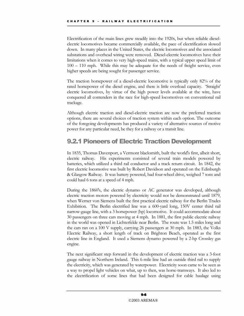
Figure 9-2 Early Catenary - Courtesy of Ian Hayes, LTK, Inc.
©2003 AREMA®
C H A P T E R 9 � R A I L W A Y E L E C T R I F I C A T I O N
9999----8888
Commercial service commenced in 1907, but not without many serious technical problems in every area of the power supply and the locomotives. The resulting poor service was recognized with apologies to the public, while claiming that the steam service that had been replaced had not been any better.
In 1904, the world's first single-phase 15,000 V, 15 Hz AC locomotive went into service in Switzerland. Weighing 44 tons, its 400-hp AC motor was only capable of a maximum speed of 47 mph and ran until 1958. Since the early 1950s, many of the earlier 15, 16 or 25 Hz power supplies have been replaced by 50 or 60 Hz systems. These are the �commercial� or 'industrial' frequencies at which utilities generate their power, depending on the country. The most famous system to retain it's original configuration of 12.5 kV 25 Hz is the former Pennsylvania Railroad portion of the Northeast corridor from New York to Washington DC, now operated by Amtrak.
Transit operators rapidly changed from horse, cable and steam propulsion to electric traction. By 1920, virtually every large city and many small cities boasted electrically powered transit lines in the form of streetcar, interurban, subway and elevated railway operations.
The balance of the 20th century was not kind to the electrified mileage in North America. The Great Depression killed most of the planned railway electrification extensions, with the exception of the Pennsylvania Railroad�s electrification from Philadelphia to Washington, and the Reading Company�s commuter electrification in the Philadelphia area, both undertaken in the 1930's. These were the last major United States passenger electrification projects until the 1990s, when Amtrak finally bridged the gap between New Haven and Boston in 1999.
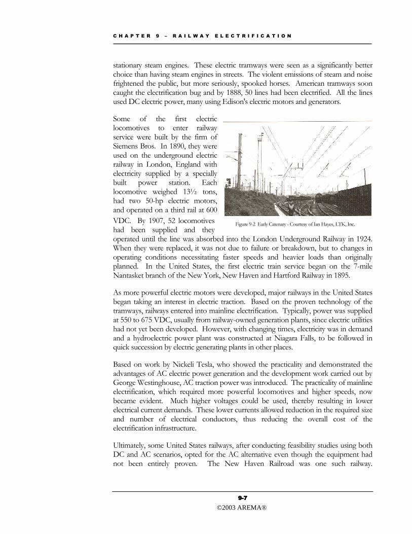
The French Railways started pushing the limits of high-speed rail further by developing trains that were eventually capable of operating at speeds up to 200 mph, and based on testing of an upgraded TGV unit, speeds of up to of 320 mph. In Japan, the bullet train speed was recorded at 277 mph with trains operating commercially at 168 mph. Amtrak�s high-speed trainsets (shown right), operating on the Northeast Corridor, are eight-car, 12,500 hp units capable of speeds up to 150 mph. These trainsets also tilt, allowing trains to travel through curves at higher than normal operating speeds without affecting passenger comfort.
Since the 1970's, many countries, most notably France, Germany, Italy, Spain and Japan (and more recently Britain, South Korea, China and Taiwan), have started to implement passenger train operations at speeds in excess of 160 mph, using new track alignments. In these trains, the locomotives are integrated into the design of
Figure 9-3 Amtrak ACELA in NEC - Courtesy of LTK, Inc.
©2003 AREMA®
C H A P T E R 9 � R A I L W A Y E L E C T R I F I C A T I O N
9999----9999
permanently coupled trainsets of six to fourteen cars with driving cabs at each end. Propulsion systems may be distributed throughout the train (so that the train is a mix of motor and trailer cars) or located in dedicated power cars at each end of the trainset. These types of trainsets are invariably �straight� electrics, which operate under high-voltage overhead contact wire systems. The alternative diesel-electric technology has been successfully developed for train speeds up to 140 mph outside the United States where unit loads are not as great.
9.3 Rail Operation Classification The advent of the diesel-electric locomotive sounded the death knell for North American electrified railways, built solely to replace steam locomotive issues addressing steep grades and tunnel ventilation. Most of these installations were taken out of service in the 1950�s. The former Milwaukee Road electrified territory lasted until the 1970�s, while Conrail abandoned use of the ex-PRR electrified territory for freight purposes in the early 1980's. As a result, with the exception of a few specialized industrial lines, all surviving electrified railways owe their continued existence to passenger operations.
Rail operations in North America serve a wide variety of transportation modes, from freight to long distance intercity travel, to daily commuter trips, to local urban transit services. These operations encompass a diversity of vehicle types, operating speeds, right-of-way requirements and service frequencies. For purposes of this chapter, the various types of rail operations will be divided into the following categories:
• Mainline and independent Short Lines • Freight � general and single product mineral heavy-haul (unit trains) • High-Speed Rail (�HSR�) • Heavy Haul � privately owned (captive fleets) • Urban • Metro • Commuter Rail • Rapid Transit (�RT� or �heavy-rail� transit) • Light Rail Transit (�LRT�) • Street Car The general characteristics of electrification of each of these rail modes are described below:
Mainline railway operations (high speed rail, intercity and commuter rail) tend towards higher speeds and longer routes, utilizing equipment that is generally compatible with freight equipment. Diesel-electric propulsion is the most typical power for passenger rail services. There are some notable exceptions:
©2003 AREMA®
C H A P T E R 9 � R A I L W A Y E L E C T R I F I C A T I O N
9999----10101010
Freight railways are almost all diesel-electric, with the exception of some mineral unit trains, and heavy-haul dedicated short lines electrified at 25 kV, 60 Hz and 50 kV, 60 Hz.
High-Speed and most Intercity services on the Northeast Corridor (NEC) are electrified with 12.5 kV, 25 Hz; 12.5 kV, 60 Hz; 25 kV, 60 Hz traction power systems, using a catenary-type overhead contact system (OCS). At the time of this writing, the Northeast Corridor (NEC) is the only North American rail line with high-speed operations.
Heavy Haul railways are lines are typically less than 1000 miles in length and operated by multiple electric or diesel-electric locomotives with up to 200 cars. Loads can range up to 20,000 tons for iron ore or coal trains. Fifteen hundred VDC, 25 kV AC and 50 kV AC systems are used and examples exist in the United States, South Africa, Australia and New Zealand.
Most Commuter Rail operations in the Northeast are electrified. Examples include:
��Metro-North: 650 VDC under-running third rail (ex-New York Central) and 12 kV, 60 Hz (New Haven Line);
��Long Island Rail Road: 600 VDC over-running third rail;
��New Jersey Transit: 12 kV, 25 Hz OCS and 25 kV, 60 Hz OCS (ex-Lackawanna 3000 VDC lines);
��SEPTA: 12 kV, 25 Hz OCS; and
��MARC: 12 kV, 25 Hz.
Electrified commuter services in the Chicago area include:
��South Shore/NICTD (former CSS&SB): 1500 VDC, OCS and
��Metra Electric (ex-Illinois Central): 1500 VDC, OCS.
Transit systems (heavy and light-rail) typically have speeds of 50 to 80 mph and shorter routes, but generally higher service frequencies. For that reason, transit operations utilize smaller and lighter vehicles. The vast majority of transit operations are electrified. All Rapid Transit and all but a few LRT systems utilize self-propelled EMUs. North American electric transit systems are almost exclusively DC systems. Power may be distributed to trains by an overhead contact system (OCS) or by third rail (over-running or under-running):
��Systems built prior to 1980 are typically 600 VDC.
©2003 AREMA®
C H A P T E R 9 � R A I L W A Y E L E C T R I F I C A T I O N
9999----11111111
��Systems built after 1980 typically utilize a 750 VDC standard.
��San Francisco�s Bay Area�s BART system represents a unique case, using a 1000 VDC system.
��Seattle Sound Transit plans to use a 1500 VDC LRT system with OCS (proposed at this writing).
��Vintage trolley operations are typically electrified at 600 VDC.
9.4 Mainline Railways and Independent Short Lines Existing mainline railways may be characterized as being for freight or for high-speed, and all rely upon electric or diesel-electric locomotives. Each type has its advantages, however electric locomotives require an additional large investment in fixed equipment, comprising an electrical infrastructure that includes substations and a traction power distribution system.
Independent heavy haul railways are frequently privately owned and operated for the sole purpose of moving bulk commodities, such as coal or iron ore from a mine to a power station, plant or a harbor, using unit heavy haul trains. Several of these are electrified operations including: Sisher Saldenha in South Africa, Coccle Hampton lines in Australia, and Black Mesa and Deseret Western lines in the United States.
Electrification of a railway can usually be justified if there is:
��A call for very high speed (over 120 mph)1
��A need to reduce reliance on fossil fuels
��A high volume of traffic
��A significant length of tunnels
��A high level of traffic sustained throughout the day, the week, the year.
��Need to reduce trip times
For freight railways, electrification may be justified if there is a need to: 1 Reducing track curvatures, introducing �tilt� trains, or a combination of both may accomplish the application of a very high-speed system on an existing railway.
©2003 AREMA®
C H A P T E R 9 � R A I L W A Y E L E C T R I F I C A T I O N
9999----12121212
��Increase capacity without adding tracks2
��Shorten delivery times by increasing running speeds
��Reduce maintenance costs by phasing out obsolete units, or
��Electrical power is available
9.4.1 Mainline Electrification Studies Before analyzing the pros and cons of an electrified system versus a wholly diesel-electric operation, it is necessary to compare the performance characteristics of each type of locomotive from an operations view point, while playing down relative cost. Relative cost will inevitably appear in the cost analysis anyway. The major difference between electric and diesel-electric motive power is that each diesel locomotive carries its power source while the power for all electric locomotives is supplied to them at the point of need.
Comparing electric locomotives to diesel-electric locomotives, it is found that electric locomotives:
��Have higher speed capabilities.
��Have lower fuel costs because the electricity generated for traction effort has a higher thermal efficiency when secured from large power plants as compared to comparatively small on-board diesel power plants.
��Are able to utilize alternate energy sources such as coal, nuclear and hydroelectric power.
��Have no local emissions to pollute air and have fewer fire and life-safety issues in underground stations or tunnels.
��Do not require fueling plants, eliminating an environmental hazard of possible fuel leakage and spillage.
��Can employ regenerative braking whereby traction motors become generators, putting power back into the contact system for another train in the circuit to utilize
2 A decision to electrify may involve selective tracks, typically mainlines and passing sidings. Branch lines, yards and sidings along the route can remain diesel operated, typically using switchers or a special applications locomotive, such as a 'dual-mode' locomotive or an 'electro-diesel.' The 'dual-mode' locomotive that can handle branch lines is a mainline diesel-electric locomotive fitted with a pantograph and electrical equipment. The 'electro-diesel' is a mainline electric locomotive fitted with a small diesel generator set, which can provide slow speed operations off-wire in yards and sidings.
©2003 AREMA®
C H A P T E R 9 � R A I L W A Y E L E C T R I F I C A T I O N
9999----13131313
(potentially reducing the overall system power consumption by as much as 10% or more).
��For equal rated horsepower, the straight electric locomotive has superior wheel-rail adhesion through better management of available traction, making them better at handling track grades, and allowing the use of steeper gradients with consequent savings in track and in civil structures.
��The straight electric locomotive has a short-term horsepower rating up to double the nominal horsepower rating, which is ideal for accelerating trains and ascending grades.
��Are not limited in horsepower by the size of the on-board diesel engine. (Electric locomotives can exceed their nominal power ratings for short periods of time, thus, improving their acceleration and run times.)
��Can increase line capacity without increasing infrastructure, by running a given route much more quickly than a diesel train due to their speed and superior acceleration and braking rates.
��Provide better track utilization by maximizing the number of trains that can fit in a given area at any one time.
��Does not present the fire hazard of onboard fuel tanks that may prevent diesel-electrics from operating in tunnels and underground stations, due to local fire codes.
��May have lower locomotive maintenance costs than diesel-electric locomotives over the expected service life.
On the other hand, diesel-electric locomotives have certain advantages over electric locomotives:
��Has a lower initial capital cost since they don�t require a power distribution system.
��Does not require an extremely elaborate and expensive power distribution system infrastructure, spread over the full length of the rail network, exposed to the elements and requiring continuous surveillance and on-site maintenance.
��Can operate independent of a power distribution system over long distances.
��Will operate during any level of failure of the electrical supply network.
��Does not create possible electrical safety hazards to the public due to the presence of the bare conductors of the contact system.
©2003 AREMA®
C H A P T E R 9 � R A I L W A Y E L E C T R I F I C A T I O N
9999----14141414
When the cost of diesel fuel was 9 cents a gallon and the supply seemed unlimited, United States railways were not interested in alternative methods of propulsion. Railway electrification interest peaks during times of uncertainty in the energy industry. When fuel rose to 34 cents per gallon and the oil embargos occurred, much effort was expended studying alternatives to hydrocarbon fuels. Studies showed that "an estimated 34% savings in energy could be achieved by using electric power. Electrification of just 10% of the (then) present rail trackage (in the densest traffic corridors) could result in a 40% reduction in railway diesel fuel consumption.�
Studies made in the 1970�s also showed that approximately 6 years after electrifying a route, the operating cost would break even when compared to the operating cost of diesel service. At 30 years, the annual operating cost of an electrified system would be one-third that of diesel service. In other words, over the effective life of a railway, the cost to operate a diesel-electric system far exceeds that of an electric system. These increased costs mainly come from the price of fuel and maintenance. Diesel locomotives average 3 to 10 gallons or more of fuel per mile and three times the amount of maintenance of straight electric locomotives.
The most significant aspect arising from these studies is that in order to realize the long-term savings, a huge capital investment is needed. Even when engineering economic studies show that an electrified system would be beneficial, raising enough money to perform the capital upgrade is a daunting challenge. Private railways would most likely require government assistance or financing from the utilities.
9.4.2 Mainline Infrastructure Compatibility
The electrification of a section of existing mainline cannot be undertaken without considering the requirements that the electric locomotives, substations, overhead or third rail power distribution systems and traction return system will place on the existing rail infrastructure.
The more significant issues are noted below:
��Tracks may need to be upgraded, including new track work or re-alignment. Sites must be found and real estate acquired for substations. In rights-of-way with restrictive width, the location of the system-wide ductbank requires coordination with track drainage, the foundations for OCS poles and emergency walkways. In all cases, maintenance access must be provided.
��If DC traction is used, the effects of electrolytic corrosion due to leakage (stray) currents must be mitigated.
��Additional clearance may need to be provided in tunnels and at bridges. Existing civil structures may have insufficient clearance to accommodate the proposed electrification system. It may be necessary to lower tracks through overhead
©2003 AREMA®
C H A P T E R 9 � R A I L W A Y E L E C T R I F I C A T I O N
9999----15151515
crossing bridges. New bridges resulting from grade-crossing elimination will need to be built with adequate electrical clearance. Future widening of existing overhead bridges must be considered.
��Tunnels may be suitable for electrification, or may require costly remedial work, enlargement or �daylighting.�
��Integration of the electrification support structures with existing station canopies must be considered. Station canopies that project over platform edges may need modification.
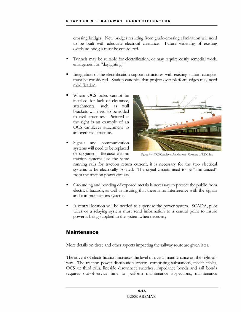
��Where OCS poles cannot be installed for lack of clearance, attachments, such as wall brackets will need to be added to civil structures. Pictured at the right is an example of an OCS cantilever attachment to an overhead structure.
��Signals and communication systems will need to be replaced or upgraded. Because electric traction systems use the same running rails for traction return current, it is necessary for the two electrical systems to be electrically isolated. The signal circuits need to be �immunized� from the traction power circuits.
��Grounding and bonding of exposed metals is necessary to protect the public from electrical hazards, as well as insuring that there is no interference with the signals and communications systems.
��A central location will be needed to supervise the power system. SCADA, pilot wires or a relaying system must send information to a central point to insure power is being supplied to the system when necessary.
Maintenance
More details on these and other aspects impacting the railway route are given later.
The advent of electrification increases the level of overall maintenance on the right-of-way. The traction power distribution system, comprising substations, feeder cables, OCS or third rails, lineside disconnect switches, impedance bonds and rail bonds requires out-of-service time to perform maintenance inspections, maintenance
Figure 9-4 OCS Cantilever Attachment - Courtesy of LTK, Inc.
©2003 AREMA®
C H A P T E R 9 � R A I L W A Y E L E C T R I F I C A T I O N
9999----16161616
adjustments and renewal of componetry. In addition, working around electrified lines is more difficult because clearance from the traction power system has to be maintained or the area will require de-energizing with the loss of track occupancy time.
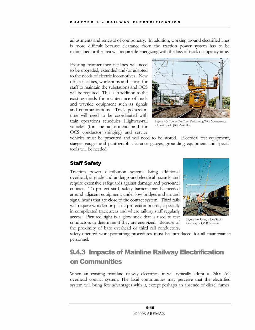
Existing maintenance facilities will need to be upgraded, extended and/or adapted to the needs of electric locomotives. New office facilities, workshops and stores for staff to maintain the substations and OCS will be required. This is in addition to the existing needs for maintenance of track and wayside equipment such as signals and communications. Track possession time will need to be coordinated with train operations schedules. Highway-rail vehicles (for line adjustments and for OCS conductor stringing) and service vehicles must be procured and will need to be stored. Electrical test equipment, stagger gauges and pantograph clearance gauges, grounding equipment and special tools will be needed.
Staff Safety
Traction power distribution systems bring additional overhead, at-grade and underground electrical hazards, and require extensive safeguards against damage and personnel contact. To protect staff, safety barriers may be needed around adjacent equipment, under low bridges and around signal heads that are close to the contact system. Third rails will require wooden or plastic protection boards, especially in complicated track areas and where railway staff regularly access. Pictured right is a glow stick that is used to test conductors to determine if they are energized. Because of the proximity of bare overhead or third rail conductors, safety-oriented work-permitting procedures must be introduced for all maintenance personnel.
9.4.3 Impacts of Mainline Railway Electrification on Communities When an existing mainline railway electrifies, it will typically adopt a 25kV AC overhead contact system. The local communities may perceive that the electrified system will bring few advantages with it, except perhaps an absence of diesel fumes.
Figure 9-5 Tower Car Crew Performing Wire Maintenance - Courtesy of Q&R Australia
Figure 9-6 Using a Hot Stick -Courtesy of Q&R Australia
©2003 AREMA®
C H A P T E R 9 � R A I L W A Y E L E C T R I F I C A T I O N
9999----17171717
Not only will local townspeople not have any use for it, but also it will likely create few jobs and will unfortunately bring with it several distinct disadvantages to the communities through which it passes. These include:
��Highly visible OCS poles and wiring
��More intensive train service, meaning more noisy periods
��Higher train speeds creating more vibration
��Possible electromagnetic interference (EMI) with overhead cables and telecommunications lines
��Electrical interference affecting TV screens
��Electromagnetic field issues
��Safety issues
All of these issues are addressable and must be addressed in the Environmental Impact Study that precedes public approval of the electrification project.
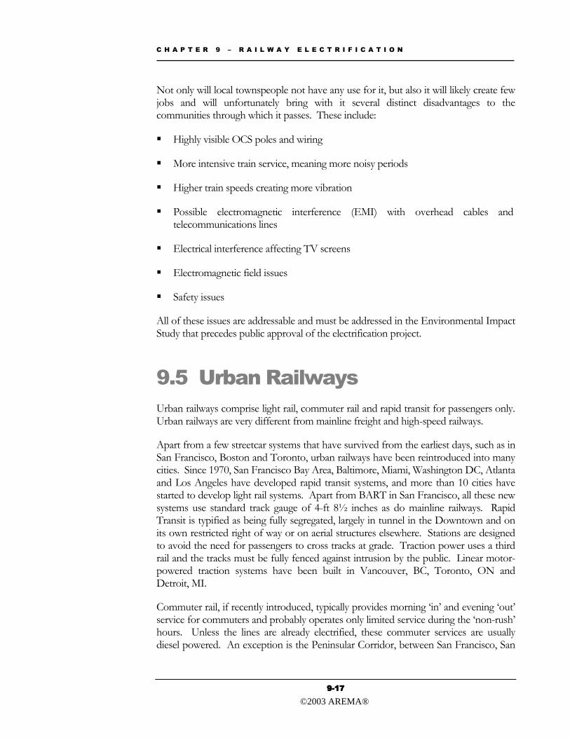
9.5 Urban Railways Urban railways comprise light rail, commuter rail and rapid transit for passengers only. Urban railways are very different from mainline freight and high-speed railways.
Apart from a few streetcar systems that have survived from the earliest days, such as in San Francisco, Boston and Toronto, urban railways have been reintroduced into many cities. Since 1970, San Francisco Bay Area, Baltimore, Miami, Washington DC, Atlanta and Los Angeles have developed rapid transit systems, and more than 10 cities have started to develop light rail systems. Apart from BART in San Francisco, all these new systems use standard track gauge of 4-ft 8½ inches as do mainline railways. Rapid Transit is typified as being fully segregated, largely in tunnel in the Downtown and on its own restricted right of way or on aerial structures elsewhere. Stations are designed to avoid the need for passengers to cross tracks at grade. Traction power uses a third rail and the tracks must be fully fenced against intrusion by the public. Linear motor- powered traction systems have been built in Vancouver, BC, Toronto, ON and Detroit, MI.
Commuter rail, if recently introduced, typically provides morning �in� and evening �out� service for commuters and probably operates only limited service during the �non-rush� hours. Unless the lines are already electrified, these commuter services are usually diesel powered. An exception is the Peninsular Corridor, between San Francisco, San
©2003 AREMA®

C H A P T E R 9 � R A I L W A Y E L E C T R I F I C A T I O N
9999----18181818
Jose and Gilroy, which is planned to be electrified. Electric locomotives could easily serve commuter lines south of Boston, presently served by diesel locomotives, because the mainline south to Providence, RI is already electrified as part of the New Haven to Boston high-speed electrification program.
Light Rail (LRT) is exemplified throughout the United States as having short trains running frequently up to 21 hours a day, 365 days of the year. The trains utilize the downtown city streets, often co-existing with motor vehicles. Typically, the public can access the entire trackage, as fencing is seldom provided. Light rail service can only be integrated with mainline rail service by means of time separation of operations. Some sections of track are shared, as in San Diego (after the LRT service closes each night, the tracks can be used by diesel locomotives to move freight). Such lines must be designed for mainline railway clearances and loadings.
9.5.1 Impacts of an Urban Electrified Light Rail or Commuter Rail System on the Community The impact on the community of light rail and commuter rail electrification is quite different to that of freight railway electrification.
In the first place, the implementation of a light rail system is typically with voter approval. Light rail:
��Encourages commuters to leave their car outside of the city center.
��Reduces travel times for car owners and bus and LRT passengers.
��Reduces overall vehicle emissions.
��Typically leads to an increase in property values within walking distance of stations.
However, there are some negative issues. Light rail:
��Requires large parking facilities.
��Occupies downtown streets, thereby reducing automobile traffic flow in the city center.
��Overhead contact system (OCS) wiring is considered visually intrusive.
��Creates electrical safety issues.
��OCS safety screens on bridges may be visually intrusive.
©2003 AREMA®
C H A P T E R 9 � R A I L W A Y E L E C T R I F I C A T I O N
9999----19191919
��Size of the LRV belies their speed, creating hazards for people and road vehicles.
9.6 Existing Electrification Systems A variety of different designs of traction power systems exist and many have been in place for years. However, they can all be grouped into one of two categories, AC or DC. The most common are 11/12.5kV AC or 25kV AC overhead contact systems, 1500 VDC overhead contact systems, 600-750 VDC overhead systems and 600-750 VDC third rail systems.
In the early days of mainline electrification, the only type of traction motors available were DC drive motors derived from early tramway motors on streetcars. This resulted in DC being selected for mainline electrification projects. At the turn of the century, the Swiss and Italians experimented with using three-phase 600 VAC propulsion by using two overhead conductors and the running rail. This early three-phase system was very complex to build. In addition, there was no flexibility for operations as the traction motors were essentially constant speed, only allowing one or two operating speeds.
By the 1950�s traction power technology had improved to allow the direct distribution of electric power at commercial frequencies, either 50 or 60 Hz. By 1960, studies determined that 25 kV systems would, for most railways, produce the most cost effective design by reducing the number of supply stations needed to connect to the commercial supply grid as compared to 1500 volt or 3000 volt systems. In addition, conductor sizing could be reduced, which in turn reduces required conductor tension and allows use of lighter supporting structures. In the early 1970's, the US pioneered 50kV systems for railways in regions where there were few, if any, transmission lines. Four such lines were built in North America: The Black Mesa & Lake Powel Railway near Flagstaff Arizona; the Deseret Western railway from Vernal, Utah to Rangeley, Colorado; the high speed test track in Pueblo, Colorado; and the Tumbler Ridge Branch Line in British Columbia (electric operations on this last line recently ceased due to business conditions).
Existing electric railways can be typically identified as one of six operating scenarios. The six scenarios are:
• Inter-City, TGV, Shinkansen, ICE, Amtrak Acela Express are examples of Inter-City operations. These systems use 11/12.5 kV or 25kV AC, with or without autotransformers. Twenty-five kV AC is well proven and is the most economic electrification system under normal conditions. Older 3000 VDC systems are still
©2003 AREMA®
C H A P T E R 9 � R A I L W A Y E L E C T R I F I C A T I O N
9999----20202020
prevalent in Russia, South America and other areas around the world that chose not to change their systems.
• Heavy Haul, including Sishen-Saldhana; Black Mesa and Lake Powell; and Tumbler Ridge (British Columbia). These railways use 50kV AC, because of the limited availability of connection points to public utilities, because they generate their own power at one end of the line, or for other economies. Substation spacing is typically 40 miles apart on 50 kV systems. However, substations on the Sishen�Saldahna iron-ore line are over 80 miles apart, in order to reduce the number of long spur distribution lines from the main power network. Voltage in the catenaries can drop as far down as 25kV and the electric locomotives still operate satisfactorily. The Sishen�Saldahna iron-ore line is a case where unique needs have driven the creation of a special type of traction power system.
• Commuter Rail, typified by older suburban lines that do not use streets to penetrate into the city they serve, such as around New York, Chicago, Baltimore; London, Birmingham and Newcastle in England and around Sydney and Brisbane, Australia. These lines operate in segregated right-of-way with no authorized public access. Some are third rail systems; some are 25kV AC. The lines that formed the old Southern Railway System in England (which today cover at least 1000 miles of route, including about 150 miles of four-track route, the rest being primarily two-track) form one of the world�s largest 660 volt third rail distribution systems. New York, which banned steam locomotives in the early 1900s, quickly developed third-rail subway service that operates at 625 volts. Sydney and Melbourne in Australia have extensive 1500 volt DC systems. Suburban lines to the north of London were originally converted from steam using the 1500 volt overhead DC system; but in 1956, British Railways selected 25kV as standard and all lines were converted from 1500 volts DC to 25kV AC. The London Underground System, although using sub-surface tracks and deep �Tube� tunnels, radiates well out of the city to the north, having taken over some of the old steam tracks of earlier railways. It uses two �third-rails,� one located in the customary position outside of the running rails and the other midway between the running rails. Extensions to existing third rail systems might also be third rail for uniformity, but dual voltage AC/DC systems operate very successfully in London. All commuter rail systems are � heavy rail.�
• Metrorail, (actually METRO) is the name given to heavy rail systems built since 1970 and include WMATA in Washington DC, MARTA in Atlanta; BART in the San Francisco Bay Area; and the Los Angeles Red Line. Metrorail systems may have extensive lengths of tunnels and/or elevated sections where an overhead contact system would be considered unaesthetic or impractical. Consequently, all use DC third rail systems with voltages of 750 volts, except BART, which uses 1000 volts.
• Light Rail, including systems in MTDB, San Diego; RT Sacramento; VTA, San Jose; Tri-Met, Portland; RTD, Denver; Metro, Buffalo; MTA, Baltimore; RTA, Cleveland; PAT, Pittsburgh; MUNI, San Francisco, DART, Dallas; UTA, Salt Lake City; Metro,
©2003 AREMA®
C H A P T E R 9 � R A I L W A Y E L E C T R I F I C A T I O N
9999----21212121
Houston; Hiawatha, Minneapolis; Sound Transit Seattle; and Calgary. All of these agencies use DC overhead contact systems, and much is installed in city streets. Downtown, a single contact wire may be installed for aesthetic reasons, but underground parallel feeder cables must supplement it, which makes for a relatively expensive installation. Low-profile catenary systems with low visual impact can be considered as a more economical alternative in some cases.
MTDB, RTA and MUNI use 600 volts; Metro Buffalo and PAT, use 650 volts; and the rest, except Seattle (1500volts), use 750 volts.
• Street Car, typified by TTC, Toronto, which still uses trolley poles on their 240 streetcars and operates at 580 volts, even though nearly every other agency which operated with trolley poles has converted to pantographs. Earlier users of trolley poles included San Francisco, Boston, Newark, NJ and the Chicago South Shore Line and every former tramway/streetcar system has since been shut down. This system is now considered out-of-date, both from an operator�s standpoint and in terms of aesthetics. Operationally, any time that the trolley pole dewires, the driver must stop to reattach the pole to the trolley wire. To do this, the operator must exit the vehicle into possibly street traffic, which is dangerous, more so at night. Second, the trolley wire must be held close to the optimum operational path of the trolley pole, which means registration guy-wires every four feet along the trolley wire at street intersections and on some sharp curves.
• ALRT, An alternative suburban electrified rail system is known as ALRT. This acronym for �Advanced Light Rapid Transit� System uses linear motor technology. Toronto has a 4-mile elevated double track system. Vancouver, British Columbia has over 20 miles of route, and Detroit uses this technology on a downtown circulator people-mover system. These standard gauge systems operate on 600 volts DC, which is collected from two side rails and fed into linear induction motors through variable-voltage variable-frequency converters.
9.7 New Electrification Systems Today, new electrification systems need to serve a wide variety of rail applications. The requirements of light rail, commuter rail, rapid transit, heavy rail, intercity, high-speed passenger service, mixed and heavy-haul freight are quite different. These different requirements result in a variety of potential electric traction system solutions.
In urban settings using city streets and malls, safety and insulation requirements (due to the close proximity to buildings, and integration with motor vehicle and pedestrian traffic) requires that light rail systems use overhead contact systems at voltages of 1500 volts DC or less. On the other hand, rapid transit and commuter rail systems, by virtue of precluding public access to the tracks, are able to use a third-rail power distribution system of 600 volts or more if the conductor rail is 'protected' and access to the right-
©2003 AREMA®
C H A P T E R 9 � R A I L W A Y E L E C T R I F I C A T I O N
9999----22222222
of-way is restricted. In these two examples, safety considerations limit the voltages. Use of lower voltage DC systems is not as efficient as high voltage AC systems. The high direct currents required at these voltages require heavy conductors, require closely spaced substations, suffer relatively high line resistance losses, and require mitigation of stray currents. However, in the case of light rail, there is no safe alternative.
For rapid transit and commuter rail, the use of third rail lowers construction cost of tunnels by reducing the tunnel bore diameter, as compared to the diameter required for pantograph operations. At one point, 600 volts DC was the preferred traction voltage because this allowed the carborne electrical gear to be simpler. However, with modern equipment this is no longer an issue.
Generally, the economic selection in terms of the cost of traction power for new mainline electrification and other systems using segregated and restricted right-of-way, will lead one to use one of the high voltage AC systems such as the 12 kV, 25kV or 25kV/25kV auto-transformer, or a 50kV system. However, every scenario will require a detailed examination to determine the feasibility of electrifying and the type of traction power system that will best serve site-specific requirements.
There are four main parts to a traction power system:
• Sources of primary power
• Substations to transform the power into a form suitable for train operations.
• A power distribution system and
• Current collectors (on the locomotives or power-cars) to draw on the power
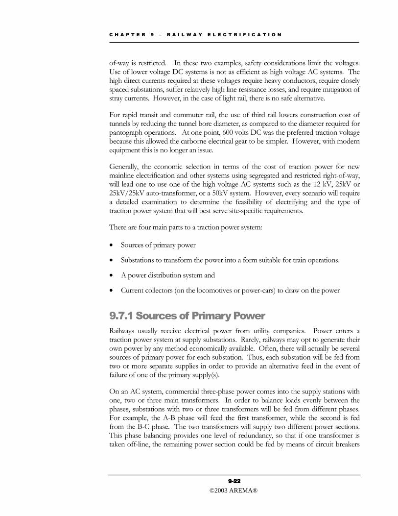
9.7.1 Sources of Primary Power Railways usually receive electrical power from utility companies. Power enters a traction power system at supply substations. Rarely, railways may opt to generate their own power by any method economically available. Often, there will actually be several sources of primary power for each substation. Thus, each substation will be fed from two or more separate supplies in order to provide an alternative feed in the event of failure of one of the primary supply(s).
On an AC system, commercial three-phase power comes into the supply stations with one, two or three main transformers. In order to balance loads evenly between the phases, substations with two or three transformers will be fed from different phases. For example, the A-B phase will feed the first transformer, while the second is fed from the B-C phase. The two transformers will supply two different power sections. This phase balancing provides one level of redundancy, so that if one transformer is taken off-line, the remaining power section could be fed by means of circuit breakers
©2003 AREMA®
C H A P T E R 9 � R A I L W A Y E L E C T R I F I C A T I O N
9999----23232323
and disconnect switches. Systems that use frequencies other than that supplied by the utility will require frequency converters to convert to the operating frequency.
On DC systems, incoming power is both stepped down and converted from AC to DC by the use of rectifier transformers. DC systems, like their AC counterparts, also have built-in redundancy by designing the traction electrification system to be able to supply enough power with one or more substations off line. In addition, steps are often taken to ensure that neighboring substations are fed off of different power sources, whether it is different power grids, different phases or different breakers coming from the same utility substation.
9.7.2 Substations
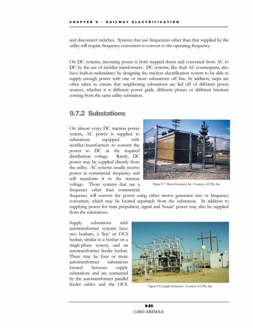
On almost every DC traction power system, AC power is supplied to substations equipped with rectifier/transformers to convert the power to DC at the required distribution voltage. Rarely, DC power may be supplied directly from the utility. AC systems usually receive power at commercial frequency and will transform it to the traction voltage. Those systems that use a frequency other than commercial frequency will convert the power using either motor generator sets or frequency converters, which may be located separately from the substation. In addition to supplying power for train propulsion, signal and �house� power may also be supplied from the substations.
Supply substations with autotransformer systems have two busbars, a �line� or OCS busbar, similar to a busbar on a single-phase system, and an autotransformer feeder busbar. There may be four or more autotransformer substations located between supply substations and are connected by the autotransformer parallel feeder cables and the OCS.
Figure 9-7 Motor Generator Set - Courtesy of LTK, Inc.
Figure 9-8 Supply Substation - Courtesy of LTK, Inc.
©2003 AREMA®
C H A P T E R 9 � R A I L W A Y E L E C T R I F I C A T I O N
9999----24242424
Each autotransformer substation has a unique autotransformer for each traction power section required.
Because components of the traction power system constitute a large capital investment, different types of protection are incorporated into the design. The cost of the substation as compared to the cost of protection is a small fraction of the capital cost. To insure that components last for their intended service life, system sectioning, primary breakers, secondary breakers, relays, PLC controls, SCADA systems and other protecting type devices are used.
A great deal of consideration is given to providing redundancy or contingency operation when designing a traction electrification system. Contingency operation plans are made at many levels. For example, the design of a typical traction distribution system allows for normal train operations even when one or more substations is off-line.
This means that the substations must be spaced and have reserve capacity to handle the normal load if any one or more is off-line. Further information on traction power system dependability is given later in this chapter.
A transmission system is sometimes used with AC systems. The use of a transmission system permits power to be moved around a system at more efficient higher voltages. In addition, if a property is large enough, a transmission system will allow multiple power sources to be utilized, providing redundancy and competitive pricing from utility companies. Multiple supplies, whether from the same utility or not, may require isolation since it is unlikely that the phases will be synchronized. Similar to phase balancing, the different sections must be separated by a phase gap. A transmissions system will require a fault detection system and load balancing. Having a trackside transmission system as a means to improve contingency operations is bought for the cost of the additional conductors and supports, although use is usually made of the OCS poles. In addition, communities may oppose such systems as they may be considered as visibly obtrusive.
9.7.3 Power Distribution Systems
Traction power distribution systems comprise three sub systems:
��Feeder cables (from the substation to the bare conductors).
��Negative return cables, connecting to the rails or the return conductor back to the substation.
©2003 AREMA®
C H A P T E R 9 � R A I L W A Y E L E C T R I F I C A T I O N
9999----25252525
��A contact system comprising bare conductors (overhead or third rail) located along the track, from which the trains draw power through some form of sliding contact. Parallel feeder cables or auto-transformer feeder cables may electrically support the contact system.
��Vehicles collection equipment to pick up the electric current.
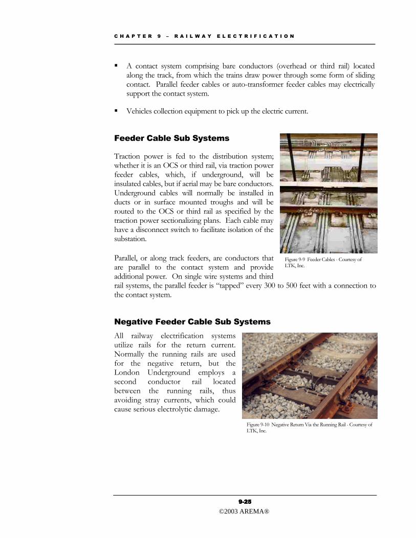
Feeder Cable Sub Systems Traction power is fed to the distribution system; whether it is an OCS or third rail, via traction power feeder cables, which, if underground, will be insulated cables, but if aerial may be bare conductors. Underground cables will normally be installed in ducts or in surface mounted troughs and will be routed to the OCS or third rail as specified by the traction power sectionalizing plans. Each cable may have a disconnect switch to facilitate isolation of the substation.
Parallel, or along track feeders, are conductors that are parallel to the contact system and provide additional power. On single wire systems and third rail systems, the parallel feeder is �tapped� every 300 to 500 feet with a connection to the contact system.
Negative Feeder Cable Sub Systems
All railway electrification systems utilize rails for the return current. Normally the running rails are used for the negative return, but the London Underground employs a second conductor rail located between the running rails, thus avoiding stray currents, which could cause serious electrolytic damage.
Figure 9-9 Feeder Cables - Courtesy of LTK, Inc.
Figure 9-10 Negative Return Via the Running Rail - Courtesy of LTK, Inc.
©2003 AREMA®
C H A P T E R 9 � R A I L W A Y E L E C T R I F I C A T I O N
9999----26262626
Contact System Sub Systems
Contact sub systems include:
��Third rail systems
��Overhead contact systems
When selecting the appropriate type of contact system for a new urban electrification, safety and reliability will be the first issue, aesthetics second, followed lastly by economics. For instance, safety precludes using a third rail system wherever the public has direct access to tracks, such as in streets, although a third rail is far less visually intrusive than an overhead system.
Contact systems, by their nature, are required to cover almost every inch of electrified track. This results in a network of very many miles of conductor wire or conductor rail. A feature of all contact systems, except for very small installations, is the provision of sectionalizing to enable segments of the traction power distribution system to be de-energized for maintenance or in an emergency. This is accomplished by the provision of disconnect and sectioning switches, enabling sections of the system to be isolated from each other, or alternatively, �tied� together for contingency operations.
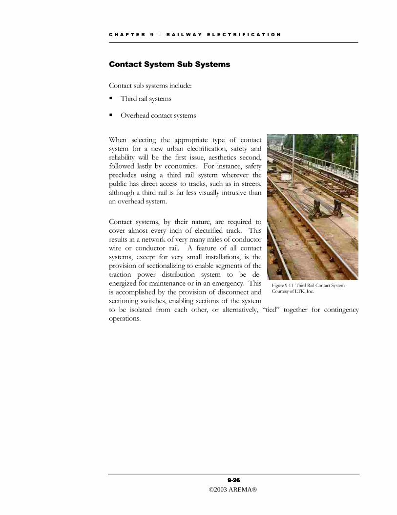
Figure 9-11 Third Rail Contact System -Courtesy of LTK, Inc.
©2003 AREMA®
C H A P T E R 9 � R A I L W A Y E L E C T R I F I C A T I O N
9999----27272727
Third Rail SystemsThird Rail SystemsThird Rail SystemsThird Rail Systems
As the name suggests, a third rail provides the positive supply in a DC powered traction system from a traction rail that parallels the track. The third rail typically rests on insulators on the field side of either side of the track. One or both running rails are used for the negative return, however a fourth rail, also on insulators, may be used.
Overhead Contact SystemsOverhead Contact SystemsOverhead Contact SystemsOverhead Contact Systems
Overhead contact systems comprise a support system (poles, wall and soffit attachments, cantilevers, cross-spans, etc.), conductors (which may be arranged in one of a variety of configurations) and anchorages to tension the conductors.
The conductor will be a continuous, energized, un-insulated contact surface suspended above the railway tracks from which electric locomotives can draw power by means of current collectors. This conductor is typically about 20 feet above the track but can range from 12 to 24 feet above top of rail.
9.7.4 Current Collectors The current collectors that draw power from the third rail or from the OCS contact wire are normally:
For third rail:
��Contact �shoe�
For OCS:
��Trolley pole or
��Pantograph
Contact Shoe
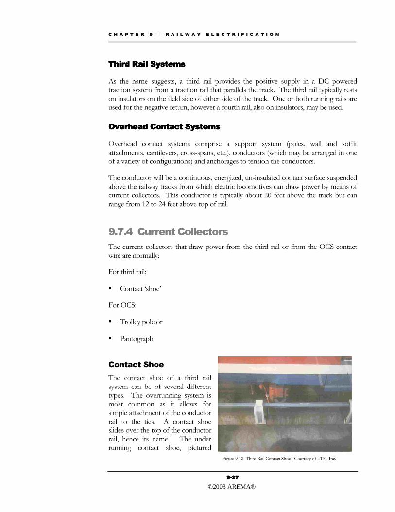
The contact shoe of a third rail system can be of several different types. The overrunning system is most common as it allows for simple attachment of the conductor rail to the ties. A contact shoe slides over the top of the conductor rail, hence its name. The under running contact shoe, pictured
Figure 9-12 Third Rail Contact Shoe - Courtesy of LTK, Inc.
©2003 AREMA®
C H A P T E R 9 � R A I L W A Y E L E C T R I F I C A T I O N
9999----28282828
right, runs along the bottom of a conductor rail that is suspended over the end of the tie. A third type is the side running contact shoe. Here, the contact shoe extends out horizontally from the vehicle and slides along the conductor rail that is again supported off the end of the tie.
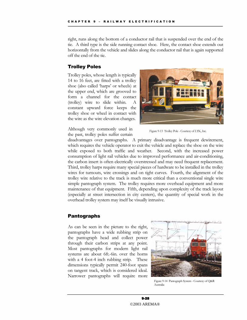
Trolley Poles
Trolley poles, whose length is typically 14 to 16 feet, are fitted with a trolley shoe (also called �harps� or wheels) at the upper end, which are grooved to form a channel for the contact (trolley) wire to slide within. A constant upward force keeps the trolley shoe or wheel in contact with the wire as the wire elevation changes.
Although very commonly used in the past, trolley poles suffer certain disadvantages over pantographs. A primary disadvantage is frequent dewirement, which requires the vehicle operator to exit the vehicle and replace the shoe on the wire while exposed to both traffic and weather. Second, with the increased power consumption of light rail vehicles due to improved performance and air-conditioning, the carbon insert is often electrically overstressed and may need frequent replacement. Third, trolley harps require many special pieces of hardware to be installed in the trolley wires for turnouts, wire crossings and on tight curves. Fourth, the alignment of the trolley wire relative to the track is much more critical than a conventional single wire simple pantograph system. The trolley requires more overhead equipment and more maintenance of that equipment. Fifth, depending upon complexity of the track layout (especially at street intersection in city centers), the quantity of special work in the overhead trolley system may itself be visually intrusive.
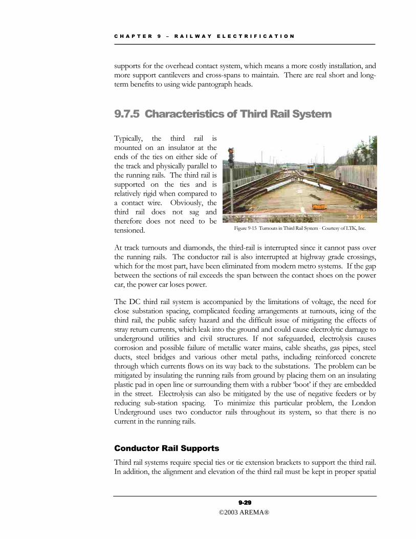
Pantographs
As can be seen in the picture to the right, pantographs have a wide rubbing strip on the pantograph head and collect power through their carbon strips at any point. Most pantographs for modern light rail systems are about 6ft.-6in. over the horns with a 4 foot-4 inch rubbing strip. These dimensions typically permit 240-foot spans on tangent track, which is considered ideal. Narrower pantographs will require more
Figure 9-13 Trolley Pole - Courtesy of LTK, Inc.
Figure 9-14 Pantograph System - Courtesy of Q&R Australia
©2003 AREMA®
C H A P T E R 9 � R A I L W A Y E L E C T R I F I C A T I O N
9999----29292929
supports for the overhead contact system, which means a more costly installation, and more support cantilevers and cross-spans to maintain. There are real short and long-term benefits to using wide pantograph heads.
9.7.5 Characteristics of Third Rail System
Typically, the third rail is mounted on an insulator at the ends of the ties on either side of the track and physically parallel to the running rails. The third rail is supported on the ties and is relatively rigid when compared to a contact wire. Obviously, the third rail does not sag and therefore does not need to be tensioned.
At track turnouts and diamonds, the third-rail is interrupted since it cannot pass over the running rails. The conductor rail is also interrupted at highway grade crossings, which for the most part, have been eliminated from modern metro systems. If the gap between the sections of rail exceeds the span between the contact shoes on the power car, the power car loses power.
The DC third rail system is accompanied by the limitations of voltage, the need for close substation spacing, complicated feeding arrangements at turnouts, icing of the third rail, the public safety hazard and the difficult issue of mitigating the effects of stray return currents, which leak into the ground and could cause electrolytic damage to underground utilities and civil structures. If not safeguarded, electrolysis causes corrosion and possible failure of metallic water mains, cable sheaths, gas pipes, steel ducts, steel bridges and various other metal paths, including reinforced concrete through which currents flows on its way back to the substations. The problem can be mitigated by insulating the running rails from ground by placing them on an insulating plastic pad in open line or surrounding them with a rubber �boot� if they are embedded in the street. Electrolysis can also be mitigated by the use of negative feeders or by reducing sub-station spacing. To minimize this particular problem, the London Underground uses two conductor rails throughout its system, so that there is no current in the running rails.
Conductor Rail Supports Third rail systems require special ties or tie extension brackets to support the third rail. In addition, the alignment and elevation of the third rail must be kept in proper spatial
Figure 9-15 Turnouts in Third Rail System - Courtesy of LTK, Inc.
©2003 AREMA®
C H A P T E R 9 � R A I L W A Y E L E C T R I F I C A T I O N
9999----30303030
relationship to the running rail. Insulators must be maintained in good condition to avoid excess current leakage.
There are three types of third rail systems: overrunning, under running and side running. Overrunning systems use a post type insulator to support the conductor rail so that the contact shoe can slide along the top. An under running system suspends the conductor rail so that the conductor shoe can slide along underneath. Lastly, a side running system supports the conductor rail so that a shoe can slide along the side of the rail.
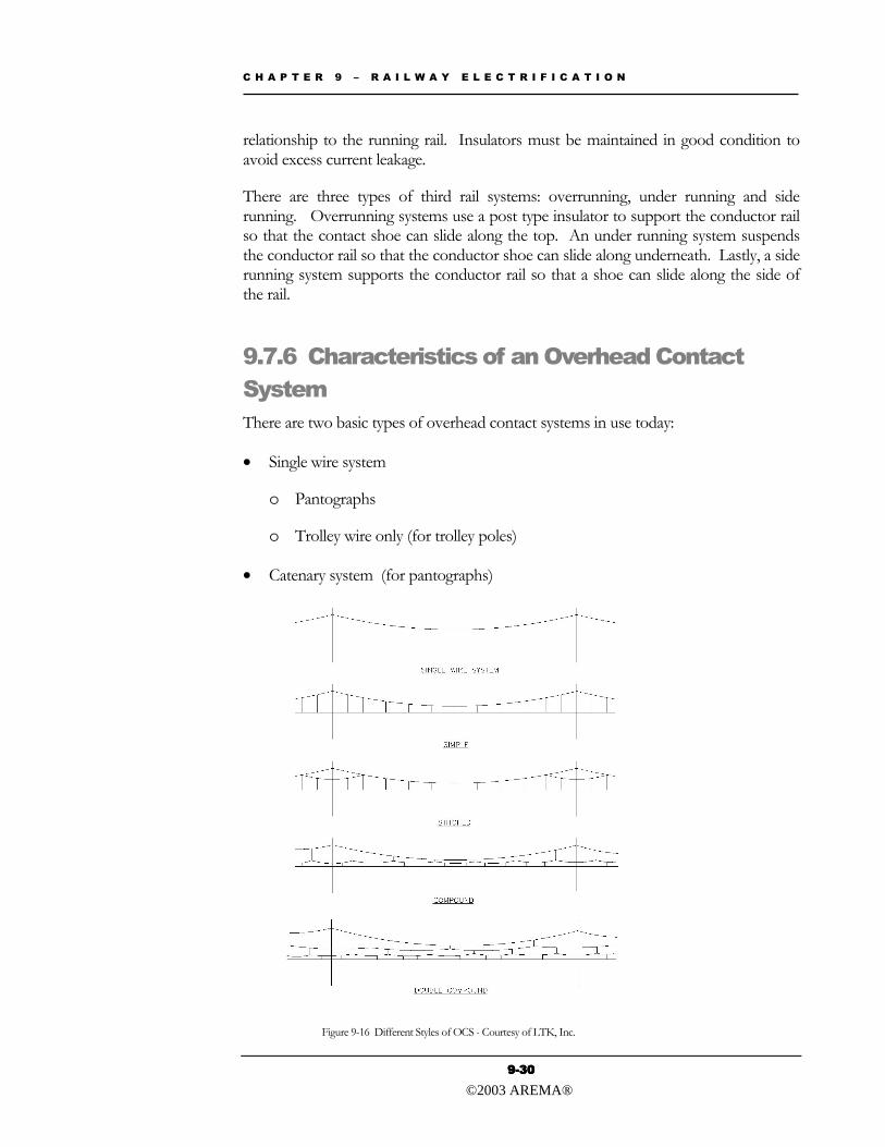
9.7.6 Characteristics of an Overhead Contact System There are two basic types of overhead contact systems in use today:
• Single wire system
o Pantographs
o Trolley wire only (for trolley poles)
• Catenary system (for pantographs)
Figure 9-16 Different Styles of OCS - Courtesy of LTK, Inc.
©2003 AREMA®
C H A P T E R 9 � R A I L W A Y E L E C T R I F I C A T I O N
9999----31313131
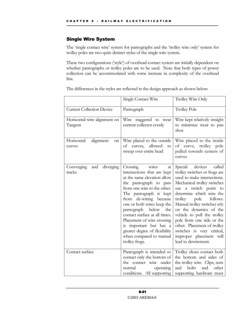
Single Wire System
The �single contact wire� system for pantographs and the �trolley wire only� system for trolley poles are two quite distinct styles of the single wire system.
These two configurations (�style�) of overhead contact system are initially dependent on whether pantographs or trolley poles are to be used. Note that both types of power collection can be accommodated with some increase in complexity of the overhead line.
The differences in the styles are reflected in the design approach as shown below:
Single Contact Wire Trolley Wire Only
Current Collection Device Pantograph Trolley Pole
Horizontal wire alignment on Tangent
Wire staggered to wear current collector evenly
Wire kept relatively straight to minimize wear to pan shoe
Horizontal alignment on curves
Wire placed to the outside of curves, allowed to sweep over entire head
Wire placed to the inside of curve, trolley pole pulled towards centers of curves
Converging and diverging tracks
Crossing wires at intersections that are kept at the same elevation allow the pantograph to pass from one wire to the other. The pantograph is kept from de-wiring because one or both wires keep the pantograph below the contact surface at all times. Placement of wire crossing is important but has a greater degree of flexibility when compared to manual trolley frogs.
Special devices called trolley switches or frogs are used to make intersections. Mechanical trolley switches use a switch point to determine which wire the trolley pole follows. Manual trolley switches rely on the dynamics of the vehicle to pull the trolley pole from one side or the other. Placement of trolley switches is very critical, improper placement will lead to dewirement.
Contact surface Pantograph is intended to contact only the bottom of the contact wire under normal operating conditions. All supporting
Trolley shoes contact both the bottom and sides of the trolley wire. Clips, nuts and bolts and other supporting hardware must
©2003 AREMA®
C H A P T E R 9 � R A I L W A Y E L E C T R I F I C A T I O N
9999----32323232
Single Contact Wire Trolley Wire Only
hardware must be kept above the contact surface.
be kept out of the area. Different types of hardware are used for trolley systems because of this.
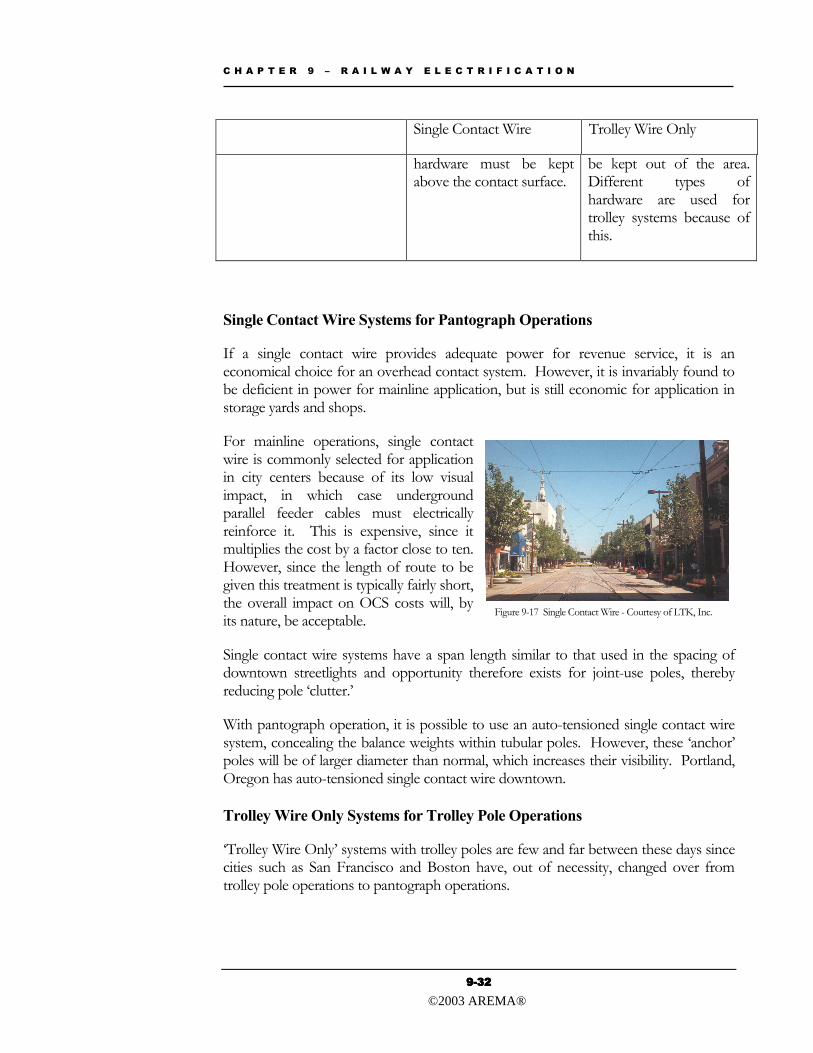
Single Contact Wire Systems for Pantograph Operations
If a single contact wire provides adequate power for revenue service, it is an economical choice for an overhead contact system. However, it is invariably found to be deficient in power for mainline application, but is still economic for application in storage yards and shops.
For mainline operations, single contact wire is commonly selected for application in city centers because of its low visual impact, in which case underground parallel feeder cables must electrically reinforce it. This is expensive, since it multiplies the cost by a factor close to ten. However, since the length of route to be given this treatment is typically fairly short, the overall impact on OCS costs will, by its nature, be acceptable.
Single contact wire systems have a span length similar to that used in the spacing of downtown streetlights and opportunity therefore exists for joint-use poles, thereby reducing pole �clutter.�
With pantograph operation, it is possible to use an auto-tensioned single contact wire system, concealing the balance weights within tubular poles. However, these �anchor� poles will be of larger diameter than normal, which increases their visibility. Portland, Oregon has auto-tensioned single contact wire downtown.
Trolley Wire Only Systems for Trolley Pole Operations
�Trolley Wire Only� systems with trolley poles are few and far between these days since cities such as San Francisco and Boston have, out of necessity, changed over from trolley pole operations to pantograph operations.
Figure 9-17 Single Contact Wire - Courtesy of LTK, Inc.
©2003 AREMA®
C H A P T E R 9 � R A I L W A Y E L E C T R I F I C A T I O N
9999----33333333
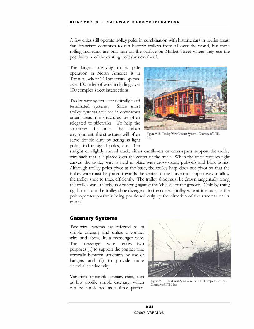
A few cities still operate trolley poles in combination with historic cars in tourist areas. San Francisco continues to run historic trolleys from all over the world, but these rolling museums are only run on the surface on Market Street where they use the positive wire of the existing trolleybus overhead.
The largest surviving trolley pole operation in North America is in Toronto, where 240 streetcars operate over 100 miles of wire, including over 100 complex street intersections.
Trolley wire systems are typically fixed terminated systems. Since most trolley systems are used in downtown urban areas, the structures are often relegated to sidewalks. To help the structures fit into the urban environment, the structures will often serve double duty by acting as light poles, traffic signal poles, etc. On straight or slightly curved track, either cantilevers or cross-spans support the trolley wire such that it is placed over the center of the track. When the track requires tight curves, the trolley wire is held in place with cross-spans, pull-offs and back bones. Although trolley poles pivot at the base, the trolley harp does not pivot so that the trolley wire must be placed towards the center of the curve on sharp curves to allow the trolley shoe to track efficiently. The trolley shoe must be drawn tangentially along the trolley wire, thereby not rubbing against the �cheeks� of the groove. Only by using rigid harps can the trolley shoe diverge onto the correct trolley wire at turnouts, as the pole operates passively being positioned only by the direction of the streetcar on its tracks.
Catenary Systems Two-wire systems are referred to as simple catenary and utilize a contact wire and above it, a messenger wire. The messenger wire serves two purposes (1) to support the contact wire vertically between structures by use of hangers and (2) to provide more electrical conductivity.
Variations of simple catenary exist, such as low profile simple catenary, which can be considered as a three-quarter-
Figure 9-18 Trolley Wire Contact System - Courtesy of LTK, Inc.
Figure 9-19 Two Cross-Span Wires with Full Simple Catenary -Courtesy of LTK, Inc.
©2003 AREMA®
C H A P T E R 9 � R A I L W A Y E L E C T R I F I C A T I O N
9999----34343434
scale version of the most economic simple catenary style. The low profile simple catenary has reduced visual impact by virtue of requiring only one cross-span wire for support between poles compared to the necessary two cross-span wires with full simple catenary as pictured (Figure 9-19). Structure spacing is, however, reduced, thus increasing the pole count by about 30%.
Nevertheless, it is still only about half the cost of a single contact wire system with parallel underground feeders, which would be electrically equivalent. Twin contact wires are also commonplace on light rail systems in Europe. Other systems using three conductors called compound catenary are operating, but are more costly and are generally not considered necessary for new installations. Compound catenary utilizes three or more conductors, with a main messenger being the top conductor, the contact wire serving as the bottom conductor, and an auxiliary messenger located between the two. Other styles, which have been installed in the past, include stitched catenary, triangular catenary and �hanging beam� catenary, and all continue in use today.
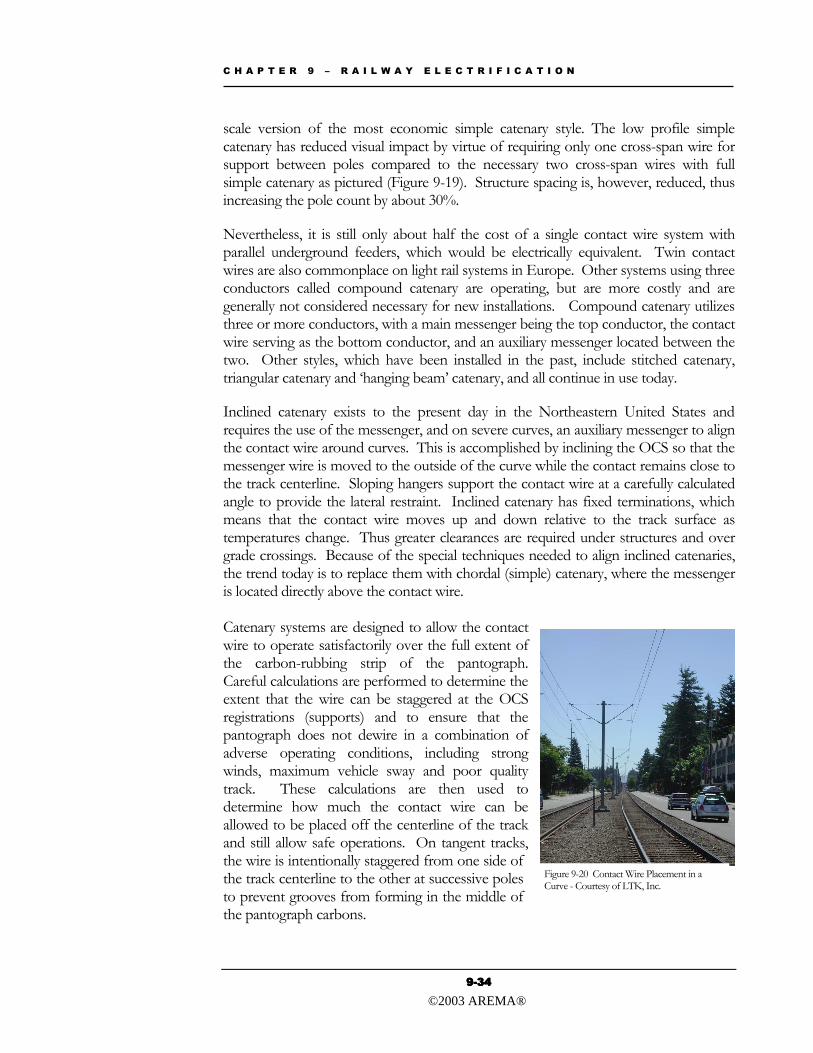
Inclined catenary exists to the present day in the Northeastern United States and requires the use of the messenger, and on severe curves, an auxiliary messenger to align the contact wire around curves. This is accomplished by inclining the OCS so that the messenger wire is moved to the outside of the curve while the contact remains close to the track centerline. Sloping hangers support the contact wire at a carefully calculated angle to provide the lateral restraint. Inclined catenary has fixed terminations, which means that the contact wire moves up and down relative to the track surface as temperatures change. Thus greater clearances are required under structures and over grade crossings. Because of the special techniques needed to align inclined catenaries, the trend today is to replace them with chordal (simple) catenary, where the messenger is located directly above the contact wire. Catenary systems are designed to allow the contact wire to operate satisfactorily over the full extent of the carbon-rubbing strip of the pantograph. Careful calculations are performed to determine the extent that the wire can be staggered at the OCS registrations (supports) and to ensure that the pantograph does not dewire in a combination of adverse operating conditions, including strong winds, maximum vehicle sway and poor quality track. These calculations are then used to determine how much the contact wire can be allowed to be placed off the centerline of the track and still allow safe operations. On tangent tracks, the wire is intentionally staggered from one side of the track centerline to the other at successive poles to prevent grooves from forming in the middle of the pantograph carbons.
Figure 9-20 Contact Wire Placement in a Curve - Courtesy of LTK, Inc.
©2003 AREMA®
C H A P T E R 9 � R A I L W A Y E L E C T R I F I C A T I O N
9999----35353535
All overhead contact systems exhibit the characteristic of increased sag between supports and loss of tension when conductor temperatures rise due to solar gain and/or current heating. Although small variations to sag and tension do not adversely affect current collection, also called �commutation,� large variations, say over 6 inches, can be unacceptable. In order to control conductor sag between supports, two options are available:
��Limit span length (length between poles)
��Tension compensation (described later)
Both options apply to Single Contact Wire (SCW) systems and to multiple conductor catenary systems to be described later.
Fixed Terminated Fixed Terminated Fixed Terminated Fixed Terminated Conductors (FT)Conductors (FT)Conductors (FT)Conductors (FT)
A typical operating temperature range for an OCS in the United States is from -10°F to 130°F. Conductor tensions are selected such that at the coldest temperature, a safety factor of 2 against breakage is available. For the contact wire, this factor of safety is preserved with the wire in the worn (typically worn 30%) condition. With no form of tension compensation, the contact wire tension in the hot condition may be so slack that the pantograph head or shoe on the trolley pole could elevate high enough to strike parts of the conductor support and registration system. To prevent this from happening, conductor spans are typically limited. For single contact wire (SCW) systems, the maximum span is typically 125 feet.
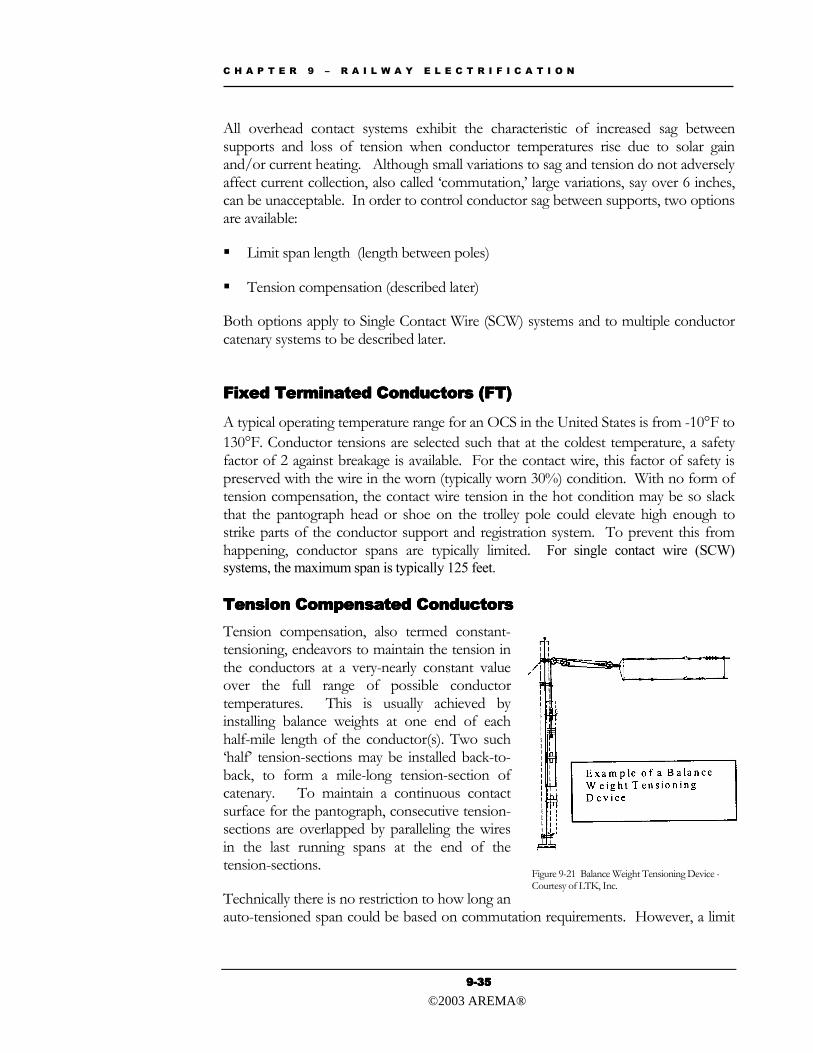
Tension Compensated CTension Compensated CTension Compensated CTension Compensated Conductors onductors onductors onductors Tension compensation, also termed constant-tensioning, endeavors to maintain the tension in the conductors at a very-nearly constant value over the full range of possible conductor temperatures. This is usually achieved by installing balance weights at one end of each half-mile length of the conductor(s). Two such �half� tension-sections may be installed back-to-back, to form a mile-long tension-section of catenary. To maintain a continuous contact surface for the pantograph, consecutive tension-sections are overlapped by paralleling the wires in the last running spans at the end of the tension-sections.
Technically there is no restriction to how long an auto-tensioned span could be based on commutation requirements. However, a limit
Figure 9-21 Balance Weight Tensioning Device -Courtesy of LTK, Inc.
©2003 AREMA®
C H A P T E R 9 � R A I L W A Y E L E C T R I F I C A T I O N
9999----36363636
will be set by determining the maximum span-length that is secure against dewirement from conductors being deflected by wind. Typical spans for constant tension equipment are as follows:
For single contact wire, SCW, maximum span is typically 125 feet, but auto-tensioned spans of 160 feet have been used very successfully.
For catenaries, maximum span is 240 feet for a pantograph width up to 6ft.-6in, although longer spans have been used with wider pantographs, (8ft.-6in) or tighter track construction and maintenance tolerances.
Other tensioning devices such as hydraulic and pneumatic tensioners have been used, but with limited success. Spring tensioners are often used on short wire runs of less than 500 feet, such as at crossovers.
Although the maximum span length on tangent tracks may be 240 feet, the maximum span lengths on curves will require considerable shortening due to the chording of the curve by the contact wire. Span length analysis is performed to determine the span/curve radius relationship.
9.7.7 OCS Style Selection
There is an almost limitless variety of configurations of OCS, but they can be broadly classified under four general styles: (1) Simple Catenary � Auto Tensioned (AT). (2) Simple Catenary � Fixed Tensioned (FT). (3) Low Profile Catenary � Fixed Tensioned (FT) (normally) (4) Single Contact Wire with Parallel Feeder, normally FT, but AT system exists in
Portland.
Style selection of OCS for mainline application is based on the following considerations:
��Location and environment
��Equivalent copper cross-sectional area
��Economics
��Speed and line characteristics
©2003 AREMA®
C H A P T E R 9 � R A I L W A Y E L E C T R I F I C A T I O N
9999----37373737
Location and Environment Location can be typified by:
o Urban o Suburban o Rural o Remote or open line
Environment can be typified by:
o Desert o Coastal o Polar o Tropical
Copper Cross-sectional Area
All four styles of catenary can be designed to be equivalent electrically and can be used for mainline service. Equivalent copper cross-sectional area can be achieved by the proper selection of messenger and contact wire sizes.
The required cross-sectional area will be determined by traction power analysis, which factors in the various parameters that represent the proposed electrification operation including:
• Track alignment
• Track profile
• Train weights
• Line speeds
• Train frequency
• Locomotive performance characteristics
• Substation locations
• Assumed substation ratings
• Climatic conditions
For light electrical duty, such as in yards and sidings, a single contact wire without parallel feeder will be adequate and economic.
©2003 AREMA®
C H A P T E R 9 � R A I L W A Y E L E C T R I F I C A T I O N
9999----38383838
In maintenance shops, conductor rail supported from roof trusses has application in special circumstances and has the advantage over a single contact wire in that it is installed untensioned, thereby avoiding horizontal tensile loads on the shop walls or door frames.
Economics
Catenary economics is a function of the following factors:
��Aesthetics
��Pole types
��Pole quantities
��Maintainability
��Selected design parameters controlling the type and quantities of poles and foundations.
AestheticsAestheticsAestheticsAesthetics
If one includes the cost of the overhead system, paired with the cost of the substation, duct backs and feeders, an auto-tensioned simple catenary is the most economic OCS style. However, some find auto-tensioned OCS less appealing aesthetically than a single contact wire style. The balance weights are often considered to be too unsightly to be used downtown and in city centers. Consequently single contact wire styles are often proposed on city streets, even though either of the other two options, Simple Catenary � Fixed-Tensioned, or Low profile � Fixed-Tensioned, would be more economic.
A concern with the single contact wire system when used downtown is that it requires an underground parallel feeder cable, which though invisible to the public, represents a large expense in underground ductbank, manholes, hand holes and insulated feeder cables. Single contact wire systems also have twice the number of poles compared to simple catenary and requires feeder-riser cables and jumpers. More poles means more support brackets, which together with the feeder connections makes for more clutter. In addition, there is more physical plant to maintain, especially because of the underground feeder cables.
Single contact wire with underground parallel feeder cables is, these days, not the preferred choice from an economic perspective. It is costly in the first place, and the underground feeder cables could turn out to be costly to repair and disruptive to road and rail operations if they fail. For these reasons, low-profile catenary is often used as an aesthetically friendly and reasonably economic style for use in city streets. Low
©2003 AREMA®
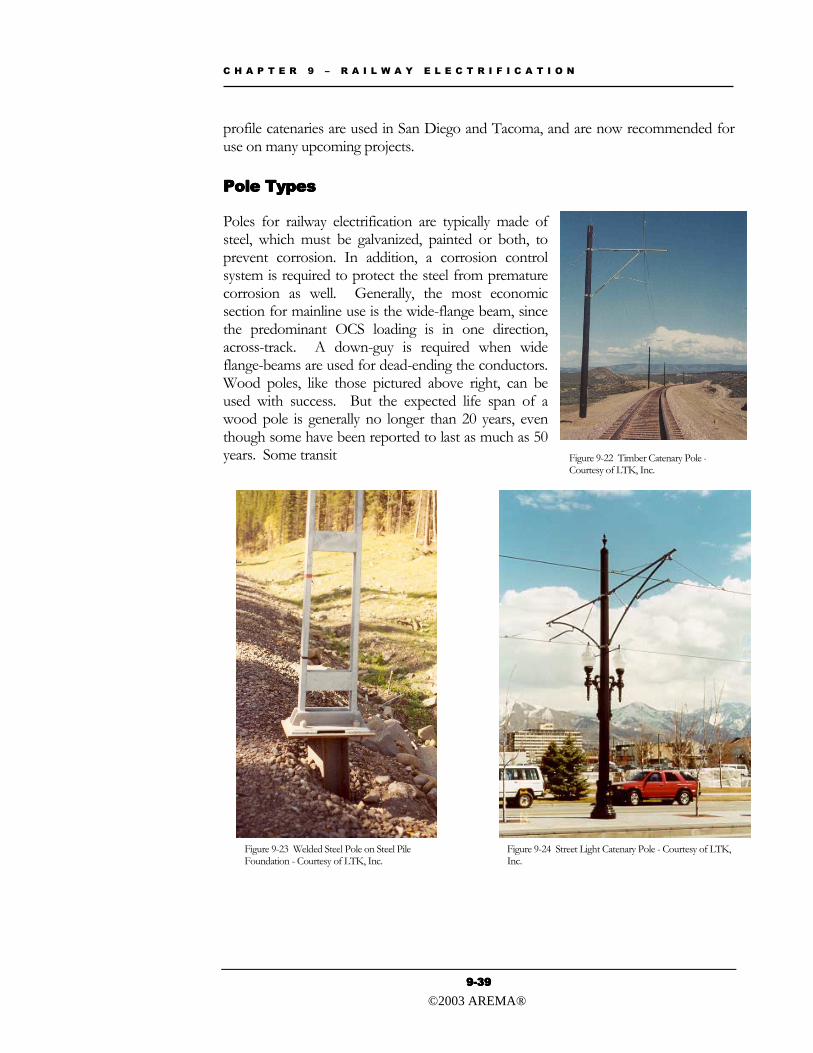
C H A P T E R 9 � R A I L W A Y E L E C T R I F I C A T I O N
9999----39393939
profile catenaries are used in San Diego and Tacoma, and are now recommended for use on many upcoming projects.
Pole TypesPole TypesPole TypesPole Types
Poles for railway electrification are typically made of steel, which must be galvanized, painted or both, to prevent corrosion. In addition, a corrosion control system is required to protect the steel from premature corrosion as well. Generally, the most economic section for mainline use is the wide-flange beam, since the predominant OCS loading is in one direction, across-track. A down-guy is required when wide flange-beams are used for dead-ending the conductors. Wood poles, like those pictured above right, can be used with success. But the expected life span of a wood pole is generally no longer than 20 years, even though some have been reported to last as much as 50 years. Some transit
Figure 9-22 Timber Catenary Pole -Courtesy of LTK, Inc.
Figure 9-23 Welded Steel Pole on Steel Pile Foundation - Courtesy of LTK, Inc.
Figure 9-24 Street Light Catenary Pole - Courtesy of LTK, Inc.
©2003 AREMA®
C H A P T E R 9 � R A I L W A Y E L E C T R I F I C A T I O N
9999----40404040
agencies use tapered tubular poles for aesthetic reasons (see below right), especially where the poles need to be in sidewalks. Some transit agencies conceal OCS feeder cables and/or balance weights inside tubular poles, again for aesthetics, but from a maintenance point of view. The difficulty in access for repair and adjustment is a drawback. For transit applications, poles are normally supplied with anchor-bolt type base plates. However, for mainline applications, direct embedment of poles into concrete foundations shows economy at the cost of reduced adjustability and flexibility for replacement.
Pole QuantitiesPole QuantitiesPole QuantitiesPole Quantities
Pole count is the indicator of an efficient and economic OCS layout. The lower the count of poles per unit length, the better for five reasons:
��Lower cost
��Fewer poles, cantilevers and headspans to inspect and maintain
��Faster installation
��Less visual intrusion
��Less risk of being damaged or demolished
The lowest pole count is obtained by maximizing the spacing of OCS poles within the constraints of the design criteria. Contributing factors to consider in maximizing the length of OCS spans are:
• Increased width of the pantograph head required in order to address issues associated with wind blow-off
• Chording of curves by the OCS
• Track quality, especially cross-level
Variations in track cross level must be accounted for when calculating the sweep of the contact wire across the pantograph head.
The location of poles is also a primary factor in pole count. Double-track transit lines often have 14-foot track centers and a single pole placed between the two tracks is ideal. However, center poles limit the redundancy of the OCS. If a center pole is damaged due to an accident, both tracks of OCS will be affected. While OCS support poles located to the field side or outside of each track require twice as many poles, a level of redundancy is achieved by maintaining the independence of each track�s OCS system.
©2003 AREMA®
C H A P T E R 9 � R A I L W A Y E L E C T R I F I C A T I O N
9999----41414141
Cost Factors of OCS Styles
Style selection must clearly be based on both aesthetics and economics. The least costly OCS style for two-track mainline is a constant tensioned simple catenary with poles between tracks. Using this style as a basis, typical cost factors for other configurations might be expected to be as follows:
Simple catenary with center poles � AT���������.
1.0
Simple catenary with center poles � FT���������. 1.1 Simple catenary with outside poles � AT��������... 1.6 Simple catenary with outside poles � FT��������... 1.8 Low profile simple catenary (only with outside poles) � FT�. 2.5 Single contact wire - FT, with underground feeder cables�� up to 10.0
All theses styles use the same types of OCS components; only the configurations of the support and termination assemblies, including cantilevers, cross-spans and head spans, counter weight terminations and fixed-end terminations are different.
OCS Design Basics
Once the OCS style or styles have been selected (based on analysis of the power demand of the trains), conductor tensions will be selected for the most economic design of the complete installed system. The design of the OCS structures are typically a function of two things, the loads being supported by the structures and the clearances necessary to allow safe passage, which is based on the dynamic envelope of the vehicle and the electrical clearance envelope.
The process of determining the loading conditions starts by examining the National Electric Safety Code (NESC). The NESC outlines loading conditions ranging from temperature ranges to wind loading. In addition, criteria are established for conductor strength requirements and factors of safety. The NESC also specifies minimum wire heights, minimum insulation levels and required clearances for various voltages that must be maintained between the OCS and structures and utilities. State and local agencies may supplement or supercede the NESC with more stringent requirements, which therefore need to be examined.
An OCS requires its own structure to support the conductors over the track. These supporting structures include:
• Portals
• Headspans
• Bracket poles
©2003 AREMA®
C H A P T E R 9 � R A I L W A Y E L E C T R I F I C A T I O N
9999----42424242
• Cantilever poles
• Cross-spans and pull-offs.
In addition, the OCS can be supported from the underside of bridges, tunnel soffits or the underside of building roof trusses. In urban areas, cross-spans can be connected to buildings using eye-bolts, thereby eliminating poles. OCS poles can be jointly shared with streetlights, traffic signals and signs.
9.8 Electrification Interfaces with Other Rail Elements When an established railway is to be electrified, there can be significant engineering and operational impacts on the existing infrastructure. The more significant impacts involve:
��Right-of-Way
��Track Structure
��Civil Structures
��Signaling and Communications
9.8.1 Right-of-Way
Track Layout/Realignment It is desirable that track alignment and modifications to track crossovers and turnouts be completed before route electrification occurs. Additionally, track renewals and track lowering measures, as described below, should have been finished. Future track improvements may need to be accelerated to avoid the need for later changes. Old redundant track should be removed before initiating electrification so that cranes are not impeded by the presence of high voltage catenary wires, conductor rails or cables.
Substations
Typically, 25kV substations require a site area of about an acre in size, with road access suitable for trucks delivering the largest piece of substation equipment. DC substations
©2003 AREMA®
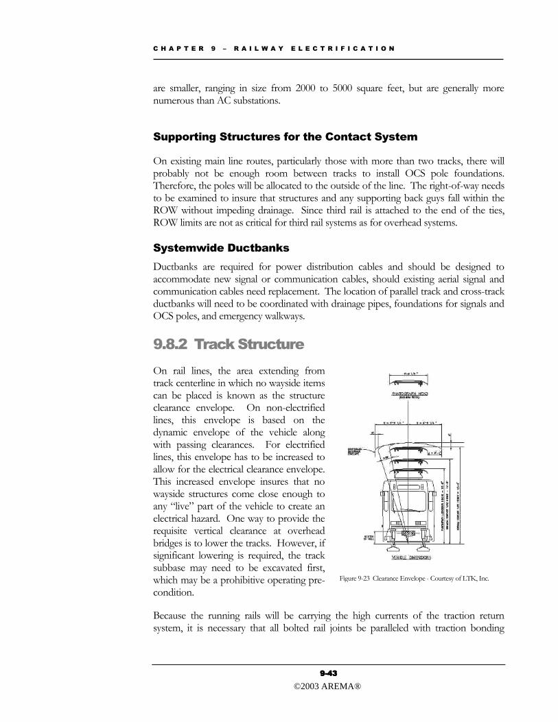
C H A P T E R 9 � R A I L W A Y E L E C T R I F I C A T I O N
9999----43434343
are smaller, ranging in size from 2000 to 5000 square feet, but are generally more numerous than AC substations.
Supporting Structures for the Contact System
On existing main line routes, particularly those with more than two tracks, there will probably not be enough room between tracks to install OCS pole foundations. Therefore, the poles will be allocated to the outside of the line. The right-of-way needs to be examined to insure that structures and any supporting back guys fall within the ROW without impeding drainage. Since third rail is attached to the end of the ties, ROW limits are not as critical for third rail systems as for overhead systems.
Systemwide Ductbanks
Ductbanks are required for power distribution cables and should be designed to accommodate new signal or communication cables, should existing aerial signal and communication cables need replacement. The location of parallel track and cross-track ductbanks will need to be coordinated with drainage pipes, foundations for signals and OCS poles, and emergency walkways.
9.8.2 Track Structure On rail lines, the area extending from track centerline in which no wayside items can be placed is known as the structure clearance envelope. On non-electrified lines, this envelope is based on the dynamic envelope of the vehicle along with passing clearances. For electrified lines, this envelope has to be increased to allow for the electrical clearance envelope. This increased envelope insures that no wayside structures come close enough to any �live� part of the vehicle to create an electrical hazard. One way to provide the requisite vertical clearance at overhead bridges is to lower the tracks. However, if significant lowering is required, the track subbase may need to be excavated first, which may be a prohibitive operating pre-condition.
Because the running rails will be carrying the high currents of the traction return system, it is necessary that all bolted rail joints be paralleled with traction bonding
Figure 9-23 Clearance Envelope - Courtesy of LTK, Inc.
©2003 AREMA®
C H A P T E R 9 � R A I L W A Y E L E C T R I F I C A T I O N
9999----44444444
cables to carry the 1000 amps or more of traction current. Defective bonds can give rise to severe arcing between the rails and cause enough damage to curtail normal train operations.
The possible effects of electrolytic corrosion due to leakage (stray) currents from the track rails, especially with DC power must be addressed. With AC systems, the effects of leakage currents is considered to be minimal, but still needs to be checked. Leakage currents can cause and/or accelerate corrosion in underground piping, steel reinforcement in concrete structures and may damage underground utilities.
Special precautions may also need to be taken to keep the track ballast free from dirt and fines, which could reduce its natural insulation value. Therefore, steps must be taken to keep the track rails insulated from ground to prevent leakage currents. Wood ties placed on good clean ballast will effectively isolate the rails from earth. These conditions must be maintained. Special rubber �boots� may be provided where the rails would otherwise be in direct contact with asphalt or similar road materials, such as at grade crossings.
9.8.3 Civil Structures
Typically, electrical clearances may need to be provided in tunnels and at bridges. New bridges (such as those resulting from grade-crossing elimination) will need to be built with adequate electrical clearance. Station canopies that project over platform edges may need modification. Provisions may need to be made to attach components to walls. OCS pole anchor bolts will need to be incorporated into any new flyovers.
Tunnels to be Electrified
If complete tunnel replacement or day-lighting is too costly, the existing ballasted track may be lowered or completely replaced by direct-fixation track. Sometimes sections of tunnel soffit may require to be �chased� to provide adequate clearance for pantographs. To reduce the space required for the OCS, cutouts or �pockets� in the soffit to house the OCS supports may be easier to provide than a more costly program of general clearance reconstruction. Third rail systems do not require the same degree of additional space as does an overhead system. Because of this, the diameter of a tunnel bore can be somewhat reduced. This reduction in tunneling requirements is one of the significant reasons why third rail is used in many of the underground �metro� systems around the world.
©2003 AREMA®
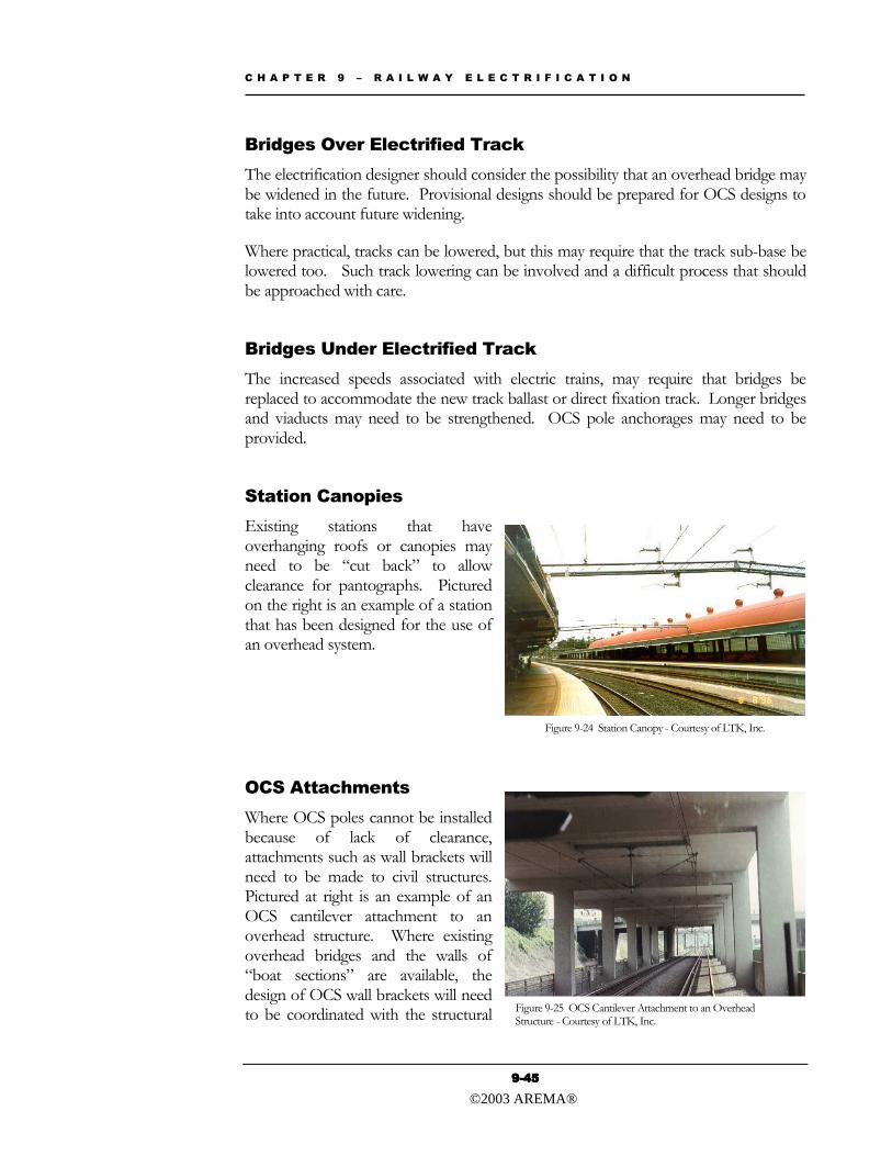
C H A P T E R 9 � R A I L W A Y E L E C T R I F I C A T I O N
9999----45454545
Bridges Over Electrified Track
The electrification designer should consider the possibility that an overhead bridge may be widened in the future. Provisional designs should be prepared for OCS designs to take into account future widening.
Where practical, tracks can be lowered, but this may require that the track sub-base be lowered too. Such track lowering can be involved and a difficult process that should be approached with care.
Bridges Under Electrified Track The increased speeds associated with electric trains, may require that bridges be replaced to accommodate the new track ballast or direct fixation track. Longer bridges and viaducts may need to be strengthened. OCS pole anchorages may need to be provided.
Station Canopies
Existing stations that have overhanging roofs or canopies may need to be �cut back� to allow clearance for pantographs. Pictured on the right is an example of a station that has been designed for the use of an overhead system.
OCS Attachments Where OCS poles cannot be installed because of lack of clearance, attachments such as wall brackets will need to be made to civil structures. Pictured at right is an example of an OCS cantilever attachment to an overhead structure. Where existing overhead bridges and the walls of �boat sections� are available, the design of OCS wall brackets will need to be coordinated with the structural
Figure 9-24 Station Canopy - Courtesy of LTK, Inc.
Figure 9-25 OCS Cantilever Attachment to an Overhead Structure - Courtesy of LTK, Inc.
©2003 AREMA®
C H A P T E R 9 � R A I L W A Y E L E C T R I F I C A T I O N
9999----46464646
designers, including the provision of wire loading values.
9.8.4 Signals and Communications As described in Chapter 7 - Communications and Signals, the running rails are used to detect the presence of trains. The signal system can precisely locate each train because the track route is first divided up by track sections, separating inbound from outbound, sidings from branches, and then dividing each track up into block sections. Each block section represents a track length between a few hundred feet and 1- 2 miles. The presence of a train is detected through electrical track circuits of the train control system, which are mimicked on a display board in the train control center(s).
In order for the traction power return circuits in the rails to be maintained without interfering with the operation of the signaling system, the two systems need to be immunized from each other. With early DC electric traction, signal circuits were converted to AC. When AC traction power was introduced, signal circuits were converted to a frequency immune to the traction frequency.
However, the use of insulated track joints in the signal system meant that the rails could not be used for the return of the traction current to the substation. Thus, the return path for the traction current was limited to through the ground and anything in the ground (such as pipes and cable sheathes), which is potentially dangerous and totally inefficient. The technical solution to this predicament was the development and use of impedance bonds that are located trackside and connect to the track rails across the insulated joint. An impedance bond is an electrical device that allows the traction current to pass through while effectively keeping the signal system�s track circuits separated. Various kinds of impedance bonds exist, depending upon whether the traction power is AC or DC, the traction voltage, and the operation frequency of the track circuits. See Table 9-1 below.
Some systems were developed that allowed one rail to be used for traction current return while the other rail was used for the signal system. This solution has a serious disadvantage in that broken rails could not be detected reliably.
Figure 9-26 Impedance Bond - Courtesy of LTK, Inc.
©2003 AREMA®
C H A P T E R 9 � R A I L W A Y E L E C T R I F I C A T I O N
9999----47474747
Table 9-1 Electrification and Signal Interface DC Traction AC Traction DC Track Circuits Cannot be used Cannot be used AC Track Circuits Requires impedance
bonds Requires impedance bonds as well as frequency variations
Coded Track/Cab signals
Requires impedance bonds
Requires impedance bonds as well as frequency variations
9.9 Interfaces with Project-Wide Staff The traction power system is only one component of a proposed new electrified mainline railway or light rail system. Detailed design work will only start once a project is authorized and funded. Planning, project definition, investment analyses and environmental studies involving the staff of the transit agency, Federal, State and local agencies must be accomplished.
Traction power distribution systems, including contact rails and overhead contact systems, are only part of the engineering that goes into an electrified railway. A number of other railway engineering disciplines (agency technical staff and architects) will require inclusion in the development of the traction power system design and installation.
The following list contains interfaces that are typical of light rail systems that share streets with motor traffic and penetrate neighborhoods. Mainline railways operate on segregated rights-of-way, which obviously avoid many of the interface issues of light rail.
Staff interfaces include:
��City engineers, planners, agencies and architects
��Agency operations and maintenance staff
��Civil consultants
��Station designers
��Design team for the maintenance facility
��Track alignment specialists and track designers
��Signals and communications staff
©2003 AREMA®
C H A P T E R 9 � R A I L W A Y E L E C T R I F I C A T I O N
9999----48484848
��Corrosion control staff
��Highway engineers
��Street lighting consultants
��Geotechnical engineers
��Consultants handling underground utilities
��Vehicle designers
Common issues for discussion with Agency staff and others, include the following:
��City engineers, planners, agencies and architects
��Fire safety requirements downtown and in tunnels, including emergency de-energization and safe condition detection
��Tapered tubular poles on sidewalks
��Historic trolley
��Aesthetic selection of OCS styles
��Ornamental poles
��Paint colors
Agency operations and maintenance staff:
��Tapered tubular poles on station platforms
��Sectionalizing requirements
��Maintenance tools and equipment
��Maintenance vehicles
Civil and structural consultants:
��Overgrade bridges, undergrade bridges, tunnels, �boat sections,� retaining walls
��Movable bridges
��Headroom for OCS
©2003 AREMA®
C H A P T E R 9 � R A I L W A Y E L E C T R I F I C A T I O N
9999----49494949
��OCS loadings on structures
Station designers/architects:
��Platforms and canopies
��Safety screening of canopy from OCS
��Grounding and bounding
Design team for the maintenance facility:
��Yard lighting
��Shop OCS
��Storage
Track alignment specialists:
��Track layout, including turnouts, crossovers and curves
��Track clearances
��Space for OCS poles between tracks
��Maintenance yard layout
Track designers:
��Special trackwork
��Traction rail bonding
Communication and signal staff:
��Aerial cables on OCS poles
��SCADA and CCTV
��Impedance bonds
��Bonding and grounding
Corrosion control consultants:
©2003 AREMA®
C H A P T E R 9 � R A I L W A Y E L E C T R I F I C A T I O N
9999----50505050
��Atmospheric pollution
��Electrolytic corrosion
��Preventive measures
Electric power utilities:
��Primary power supplies, capacity and location
��Redundant feeds
��Harmonics
Highway engineers:
��Traffic signals, height/reach of bracket arms, joint use
��Maintenance clearance from OCS for signal maintainers
Street lighting consultants:
��Joint-use of poles
Geotechnical engineers:
��Soil conditions
Consultants handling underground utilities:
��Quality of records
��Utility location
Vehicle designers:
��Pantograph criteria
��Vehicle envelope
��Electrical interface with vehicle electric equipment
Safety specialists:
��Safe working zones for maintenance
©2003 AREMA®

C H A P T E R 9 � R A I L W A Y E L E C T R I F I C A T I O N
9999----51515151
��Safe working zones under bridges and in tunnels
��Double insulation
��Screening of OCS at over bridges
��Screening along walls of boat-sections
��Warning signs
��Screening of ladders for signal posts adjacent to OCS
Bibliography 1. Journal of the International Institute of Rail Electrification Engineers, Volume 2 Issue
1, August 2001.
2. Guinness Book of Rail Facts and Feats, John Marshall, 1975.
3. �When the Steam Railroads Electrified,� W.D. Middleton, Kalmabach Press
(1974).
4. �Electrifying the Caltrain/PCS Railroad,� Caltrain, 1992.
5. �Rail 1950,� Jack Simmonds, Metheun, 1975.
6. Design of the 50 kV Overhead Contact System for the British Columbia Railway Tumbler
Ridge Branch Line, L.C. Tait and B. Anderson, IEEE, 1984.
7. �The Electric Railway,� Fred H. Whipple, 1889.
8. �Railways: Mechanical Engineering,� J.B. Snell, 1971.
9. �The Illustrated Directory of Trains of the World,� Brian Hollingsworth, 2000.
10. �American Locomotives in Historic Photographs 1858 � 1949,� Ron Ziel, 1993.
11. �The Story of the Train,� National Railway Museum, UK, 1999.
12. �Croydons Transport Through the Ages,� UK, John Gent, 2001.
13. �Electricity,� Steve Parker, 1992.
14. �Electricity in Transport,� English Electrical, 1951.
15. �Ultimate Train,� Peter Herring, 2000.
16. �Pictorial History of America�s Railroads,� Mike Del Vecchio, 1998.
©2003 AREMA®