Embed Size (px)
Citation preview

OCT 2014 Chapter 9 Rotor Systems Page 9.i
CHAPTER 9
ROTOR SYSTEMS
Section Title Page
9.000 Rotor Systems . . . . . . . . . . . . . . . . . . . . . . . . . . . . . . . . . . . . . . . . . . . . 9.19.100 Main Rotor . . . . . . . . . . . . . . . . . . . . . . . . . . . . . . . . . . . . . . . . . . . . . . . 9.1
9.110 Main Rotor Blades . . . . . . . . . . . . . . . . . . . . . . . . . . . . . . . . . . . . . . . . 9.19.111 Main Rotor Blade Removal . . . . . . . . . . . . . . . . . . . . . . . . . . . . . . . . 9.19.112 Main Rotor Blade Installation . . . . . . . . . . . . . . . . . . . . . . . . . . . . . . 9.49.113 Boot Removal . . . . . . . . . . . . . . . . . . . . . . . . . . . . . . . . . . . . . . . . 9.59.114 Boot Installation . . . . . . . . . . . . . . . . . . . . . . . . . . . . . . . . . . . . . . . 9.59.115 Filling Pitch Bearing Housing . . . . . . . . . . . . . . . . . . . . . . . . . . . . . . 9.79.116 Drilling Main Rotor Hub Bolts . . . . . . . . . . . . . . . . . . . . . . . . . . . . . . 9.7
9.120 Main Rotor Hub . . . . . . . . . . . . . . . . . . . . . . . . . . . . . . . . . . . . . . . . . 9.89.121 Main Rotor Hub Removal . . . . . . . . . . . . . . . . . . . . . . . . . . . . . . . . . 9.89.122 Main Rotor Hub Installation . . . . . . . . . . . . . . . . . . . . . . . . . . . . . . . 9.89.123 Main Rotor Hub Journal and Shim Calculations . . . . . . . . . . . . . . . . . 9.119.124 Adjustment of Hinge Friction . . . . . . . . . . . . . . . . . . . . . . . . . . . . . . 9.149.125 Shifting the Main Rotor Hub . . . . . . . . . . . . . . . . . . . . . . . . . . . . . . 9.149.126 Main Rotor Hub Bearing Replacement . . . . . . . . . . . . . . . . . . . . . . . . 9.15
9.130 Inspection of Main Rotor Blades . . . . . . . . . . . . . . . . . . . . . . . . . . . . . . 9.179.131 Scratches and Corrosion on Blade Skins and Doublers . . . . . . . . . . . . . 9.179.132 Dents and Local Deformations . . . . . . . . . . . . . . . . . . . . . . . . . . . . . 9.199.133 Root Fitting Damage . . . . . . . . . . . . . . . . . . . . . . . . . . . . . . . . . . . . 9.219.134 Voids . . . . . . . . . . . . . . . . . . . . . . . . . . . . . . . . . . . . . . . . . . . . . . 9.23
9.140 Repair of Main Rotor Blades . . . . . . . . . . . . . . . . . . . . . . . . . . . . . . . . . 9.259.141 Trimming . . . . . . . . . . . . . . . . . . . . . . . . . . . . . . . . . . . . . . . . . . . . 9.26A9.142 Painting . . . . . . . . . . . . . . . . . . . . . . . . . . . . . . . . . . . . . . . . . . . . . 9.26A
9.200 Tail Rotor . . . . . . . . . . . . . . . . . . . . . . . . . . . . . . . . . . . . . . . . . . . . . . . . 9.26C9.210 Tail Rotor Assembly Removal . . . . . . . . . . . . . . . . . . . . . . . . . . . . . . . . 9.26C
9.212 Tail Rotor Installation with Spherical Teeter Bearings . . . . . . . . . . . . . 9.279.213 Tail Rotor Installation with Elastomeric Teeter Bearings . . . . . . . . . . . . 9.309.214 Tail Rotor Hub Spherical Bearing Replacement . . . . . . . . . . . . . . . . . . 9.32A9.215 Tail Rotor Hub Elastomeric Bearing Replacement . . . . . . . . . . . . . . . . 9.32B
9.220 Inspection and Repair of Tail Rotor Blades . . . . . . . . . . . . . . . . . . . . . . . 9.33
Intentionally Blank
Page 9.ii Chapter 9 Rotor Systems OCT 2014
CHAPTER 9
ROTOR SYSTEMS
9.000 Rotor Systems
The main rotor has two all-metal blades mounted to the hub by coning hinges. The hub is mounted to the shaft by a teeter hinge. The coning and teeter hinges use self-lubricated bearings. Droop stops for the main rotor blades provide a teeter hinge friction restraint which normally prevents the rotor from teetering while starting or stopping. Pitch change bearings for each blade are enclosed in a housing at the blade root. The housing is filled with oil and sealed with an elastomeric boot. Each blade has a thick stainless steel spar at the leading edge which is resistant to corrosion and erosion. The skins are bonded to the spar approximately one inch aft of the leading edge. Blades must be refinished if the paint erodes to bare metal at the skin-to-spar bond line. Bond may be damaged if bond line is exposed.
The tail rotor has two all-metal blades and a teetering hub with a fixed coning angle. The pitch change bearings have self-lubricated liners. The teeter hinge bearings are elastomeric. The tail rotor blades are constructed with aluminum skins and forged aluminum root fittings.
9.100 Main Rotor
Refer to R22 Illustrated Parts Catalog (IPC) Chapter 62.
9.110 Main Rotor Blades
WARNING
Due to potentially destructive results, use of blade tape (anti-erosion tape) is prohibited.
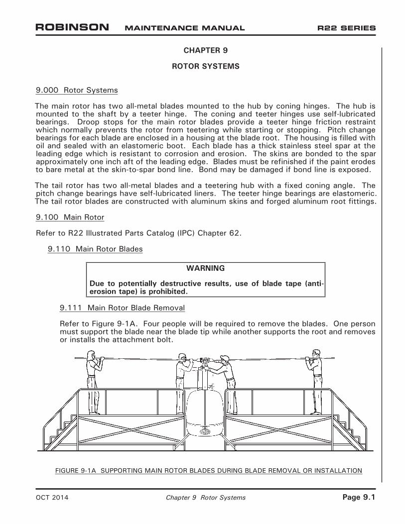
9.111 Main Rotor Blade Removal
Refer to Figure 9-1A. Four people will be required to remove the blades. One person must support the blade near the blade tip while another supports the root and removes or installs the attachment bolt.
FIGURE 9-1A SUPPORTING MAIN ROTOR BLADES DURING BLADE REMOVAL OR INSTALLATION
OCT 2014 Chapter 9 Rotor Systems Page 9.1

FIGURE 9-1B MEASURING BOLT STRETCH (SHOWN ON TEETER BOLT, BLADES REMOVED)
Page 9.2 Chapter 9 Rotor Systems OCT 2014

9.111 Main Rotor Blade Removal (continued)
1. Mark one main rotor blade and its corresponding hub location, pitch link, and retaining nut & bolt with “X” using a marker or grease pencil. Mark opposite blade and its hub location, pitch link, and retaining nut & bolt with “O”.
2. Measure and record coning hinge axial gaps per Figure 9-3A.
3. Remove hardware securing main rotor pitch links to blade pitch horns.
4. Remove cotter pins and loosen blade coning hinge retaining nuts until finger tight.
CAUTION
After removing one blade, support installed blade in a level position until it is removed.
5. Remove nut, thrust washer, and trailing-edge shims (if used) from one blade. Cone blade as required to position spindle tusk off of droop stop. Supporting blade at root, rotate pitch horn down, and remove hinge bolt and thrust washer.
CAUTION
Do not drop journals (inside hub bearings) which can slide out when removing blade bolt.
NOTE
Blade installation hardware is specific to each blade, each blade’s leading and trailing edge, and each blade’s location in hub. It is good practice after blade removal to install hardware in hub finger tight exactly as removed.
6. Place blade on a cushioned surface to prevent damage to skins.
7. Remove opposite blade per steps 5 and 6.
MAR 2016 Chapter 9 Rotor Systems Page 9.3

Page 9.4 Chapter 9 Rotor Systems MAR 2016
9.112 Main Rotor Blade Installation
1. Identify hub and spindle part numbers and ensure correct corresponding installation hardware.
2. Check teeter hinge friction and adjust as required per § 9.124.
3. If coning hinge axial gap recorded during blade removal was beyond tolerance, or if corresponding hub bearing(s) or spindle was replaced, perform coning hinge journal and shim calculation per § 9.123.
4. Level hub and insert journals in hub bearings. Install thrust washer on blade bolt.
5. Insert main rotor blade spindle in hub and align spindle and journal bores. Cone blade as required to position tusk off of droop stop. Rotate pitch horn down and install hinge bolt at leading-edge side.
NOTE
A bolt may be inserted from trailing-edge side to align spindle and journal bores (it is pushed out as coning hinge bolt is installed).
6. Install trailing-edge shims (if used) and thrust washer. Apply light coat A257-9 anti-seize to bolt threads and nut face. Install nut finger tight.
NOTE
Do not allow anti-seize to contact journals, shims, or hub bearing areas. These areas must be clean and dry.
CAUTION
After installing one blade, support blade in a level position until opposite blade is installed.
7. Install opposite blade per steps 4 thru 6.
8. Tighten nut on coning hinge bolt until journals and thrust washer are firmly seated. Loosen nut until both thrust washers can be freely rotated.
9. Refer to Figure 9-1B. Install MT122 main rotor bolt elongation (stretch) tool on hinge bolt. Zero dial indicator by rotating dial face and lock dial. Remove tool.
10. Using wrenches with at least 150 ft-lb torque capacity, tighten nut until drilled holes in nut and bolt align. Install MT122 tool and measure bolt elongation:
WARNING
Do not under-stretch or over-stretch teeter or coning hinge bolts to obtain proper clamping force. Under-stretching or over-stretching can cause failure.

9.112 Main Rotor Blade Installation (continued)
10. a. A154-1 hub with NAS630-80 (or MS21250-10080) coning hinge bolts:
i. If bolt elongation is 0.015–0.017 inch, remove tool and install a new cotter pin wet with epoxy primer.
ii. If bolt elongation is not 0.015–0.017 inch, remove old nut and old bolt and install a new bolt and a new nut. Stretch new bolt per § 1.330, and drill new nut and bolt per § 9.116. Install a new cotter pin wet with epoxy primer.
b. B370-1 hub with NAS632-82 (or MS21250-12082) coning hinge bolts:
i. If bolt elongation is 0.010–0.012 inch, remove tool and install a new cotter pin wet with epoxy primer.
ii. If bolt elongation is not 0.010–0.012 inch, remove old nut and old bolt and install a new bolt and a new nut. Stretch new bolt per § 1.330, and drill new nut and bolt per § 9.116. Install a new cotter pin wet with epoxy primer.
11. Install hardware securing main rotor pitch link to pitch horn. Standard torque hardware per § 1.320 and torque stripe per Figure 2-1.
12. Perform steps 8 thru 11 on opposite blade.
13. Track and balance main rotor blades per § 10.230.
9.113 Boot Removal
1. Remove main rotor blades per § 9.111.
2. Place a suitable drain container below pitch horn. Remove two B289-2 bolts and drain fluid.
3. Remove outer boot clamp and hold boot back to expose inner boot clamp. Remove inner clamp and peel boot from spindle.
9.114 Boot Installation
1. Visually inspect and verify boot is undamaged. Carefully stretch new boot over spindle.
2. Solvent-clean surfaces clamped by boot inner lip. Properly position boot inner lip; install A165-1 (inner) clamp assembly and tighten clamp to 2.330 ± 0.005 inch outside diameter. Rotate spindle and verify adequate clearance between clamp assembly and pitch horn.
NOTEWhen installing inner clamp, ensure that shoulder of boot inner lip is not wedged beneath clamp or clamp may loosen in service. Inspect boot interior and verify no cuts or punctures.
3. Stretch boot outer lip over pitch horn flange. Rotate spindle and align pitch horn bolt hole with spindle bolt hole per Figure 9-1C. Install A165-7 (outer) clamp assembly and tighten clamp. Verify security.
4. Fill pitch bearing housing per § 9.115.
MAR 2016 Chapter 9 Rotor Systems Page 9.5

FIGURE 9-1C FILLING PITCH BEARING HOUSING
Page 9.6 Chapter 9 Rotor Systems MAR 2016

9.115 Filling Pitch Bearing Housing
NOTE
MT147-1 Main rotor blade spindle air bleed tool includes supply container, hose assemblies, and bleed fittings.
WARNING
Refer to appropriate Material Safety Data Sheet (MSDS) and take necessary safety precautions when working in proximity to hazardous materials.
1. Remove main rotor blades per § 9.111.
2. Refer to Figure 9-1C. Place a suitable drain container below main rotor pitch horn. Remove two B289-2 bolts from pitch horn and drain fluid.
3. Install MT147-2 bleed fittings into pitch horn openings. Attach drain hose assembly to (top) bleed fitting, secure with two wraps of lockwire. Position drain hose into drain container.
4. Place supply container with sufficient A257-4 fluid approximately 3 feet above spindle. Route fill hose assembly into drain container and open brass valve. Open supply container plastic valve and purge air from fill hose. Close valves.
5. Connect brass valve to (bottom) bleed fitting by tightening brass compression sleeve.
6. Open valves and fill spindle housing until no air bubbles are visible in drain hose assembly. Massage spindle boot, oscillate spindle, and raise blade tip up & down to remove trapped air.
7. Remove drain hose assembly and (top) bleed fitting, and install B289-2 bolt. Roll the blade over. After five minutes, inspect the boot for leaks. If no leaks are found, close valves, remove fill hose assembly brass valve and (bottom) bleed fitting, and install other bolt.
8. Torque B289-2 bolts per § 1.330 and torque stripe per Figure 2-1.
9. Repeat steps for opposite blade.
9.116 Drilling Main Rotor Hub Bolts
NOTE
Protect hub from damage due to chuck contact by wrapping chuck and/or covering hub edge with several layers of tape.
New bolts and nuts must be installed and bolts stretched per § 1.330 prior to drilling.
Using a 0.125-inch diameter Cobalt twist-drill and cutting oil, drill a hole through nut and bolt using an accessible pre-drilled hole in nut. The MT569-1 and MT569-6 (B370-1 hub coning hinge bolts) drill guide assembly will facilitate drilling a perpendicular hole. If a pre-drilled hole is inaccessible, completely loosen nut, slightly rotate bolt to favorable position, then special torque per § 1.330. Protect adjacent area from drilling debris.
MAR 2016 Chapter 9 Rotor Systems Page 9.7

9.120 Main Rotor Hub
9.121 Main Rotor Hub Removal
1. Remove main rotor blades per § 9.111.
2. Refer to Figure 9-2A. Mark rotor hub using a grease pencil, tape, or soft marker as follows:
a. Indicate nut side of teeter bolt.b. Indicate chord arm side of drive shaft.
3. If same hub will be installed, measure teeter hinge friction per Figure 9-3B and record value.
4. Remove cotter pin, nut, A152 thrust washers, A117 shims, A106 journals, and bolt. Rotate hub as required and remove hub. Do not drop thrust washers or journals.
5. Reinstall bolt, thrust washers, shims, journals, and nut in rotor hub exactly as removed.
CAUTION
Main rotor chordwise balance is adjusted using A106 journals and A117 shims. If assembly stack-up is altered, an out-of-balance condition can occur.
9.122 Main Rotor Hub Installation
1. Clean and dry teeter hinge hardware using approved solvent per § 1.400. Inspect journals and thrust washers for chipping of chrome plating, corrosion, and/or wear grooves extending through chrome plating. Replace journal or thrust washer if any of these conditions exist.
2. If teeter hinge friction recorded during hub removal was less than 5 ft-lb or more than 15 ft-lb, if teeter hinge hub bearing(s) was replaced, or if previous installation information is unavailable, perform teeter hinge journal and shim calculation per § 9.123 Part A.
3. Refer to Figure 9-2A. Line up mark on hub with chord arm on drive shaft. Install teeter hinge bolt, thrust washers, shims, and journals (if previous installation information is available, install parts exactly as removed).
4. Coat nut face and bolt threads with A257-9 anti-seize compound, install and tighten nut, then loosen nut until both thrust washers can be freely rotated. Ensure journals do not “pinch” droop stops and fully contact drive shaft.
WARNING
Do not allow anti-seize compound to contaminate drive shaft, journals, shims, or thrust washer inner faces. Contamination prevents proper joint clamp-up and may cause failure.
5. Refer to Figure 9-1B. Install MT122 main rotor bolt elongation (stretch) tool on teeter bolt. Zero dial indicator by rotating dial face and lock dial. Remove tool.
Page 9.8 Chapter 9 Rotor Systems MAR 2016
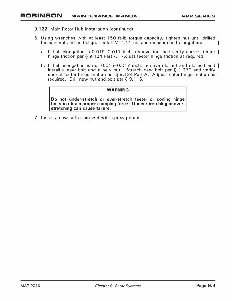
9.122 Main Rotor Hub Installation (continued)
6. Using wrenches with at least 150 ft-lb torque capacity, tighten nut until drilled holes in nut and bolt align. Install MT122 tool and measure bolt elongation:
a. If bolt elongation is 0.015–0.017 inch, remove tool and verify correct teeter hinge friction per § 9.124 Part A. Adjust teeter hinge friction as required.
b. If bolt elongation is not 0.015–0.017 inch, remove old nut and old bolt and install a new bolt and a new nut. Stretch new bolt per § 1.330 and verify correct teeter hinge friction per § 9.124 Part A. Adjust teeter hinge friction as required. Drill new nut and bolt per § 9.116.
WARNING
Do not under-stretch or over-stretch teeter or coning hinge bolts to obtain proper clamping force. Under-stretching or over-stretching can cause failure.
7. Install a new cotter pin wet with epoxy primer.
MAR 2016 Chapter 9 Rotor Systems Page 9.9

FIGURE 9-2A TEETER HINGE (HUB INSTALLATION)
FIGURE 9-2B B370-1 HUB CONING HINGE (BLADE INSTALLATION; VIEW LOOKING DOWN)
Page 9.10 Chapter 9 Rotor Systems MAR 2016

FIGURE 9-2C A154-1 HUB CONING HINGE (BLADE INSTALLATION; VIEW LOOKING DOWN)
MAR 2016 Chapter 9 Rotor Systems Page 9.10A
A106 Journal LengthsPart No. Length LocationA106-1 1.000 in. Coning hinge, no shims (A154-1 Hub)A106-2 0.995 in. Coning hinge, no shims (A154-1 Hub)A106-3 0.990 in. Coning hinge, no shims (A154-1 Hub)A106-4 1.300 in. Teeter hinge (two, or one + A106-5 per hinge), shimsA106-5 1.260 in. Teeter hinge (none, or one + A106-4 per hinge), shimsA106-6 1.005 in. Coning hinge, no shims (A154-1 Hub)A106-7 1.005 in. Coning hinge (B370-1 Hub)
A117 Shim SizesPart No. Thickness Location (Between thrust washer and journal)A117-5 0.012 in. Teeter hingeA117-6 0.015 in. Teeter hingeA117-7 0.020 in. Teeter hingeA117-8 0.025 in. Teeter hingeA117-48 0.012 in. Coning hinge (B370-1 Hub)A117-49 0.015 in. Coning hinge (B370-1 Hub)A117-50 0.020 in. Coning hinge (B370-1 Hub)A117-51 0.025 in. Coning hinge (B370-1 Hub)
TABLE 9-1 A106 JOURNAL LENGTHS AND A117 SHIM SIZES

9.123 Main Rotor Hub Journal and Shim Calculations
Refer to Table 9-1 and Figures 9-2A, 9-2B, and 9-2C.
A. Teeter Hinge Calculation
1. Measure main rotor hub width across the teeter hinge bearing faces: in.
2. Subtract measured width of A251 driveshaft at teeter hinge bolt hole: – in.
Calculated empty space: = in.
3. Assemble thrust washer, one A117-7 shim (0.020 inch), and one A106-4 journal (1.300 inches) under the teeter bolt head and insert bolt thru hub and drive shaft.
Subtract combined measured thickness of A117-7 shim &A106-4 journal: – in.
Difference: = in.
4. Subtract measured length of nut-side A106-4 or A106-5 journal: – in.
Difference: = in.
CAUTION
Initial teeter hinge hardware stack-up must be adjusted to 0.005/0.008 inch greater than calculated empty space. A smaller initial stack-up could damage thrust washers and hub bearings during installation.
5. To accommodate dimensional change due to clamping force, add: + 0.005/0.008 in.
Initial A117 shim stack between nut-side journal & thrust washer: =/
in.
NOTE
Use as many different size A117 shims as possible to facilitate head shifting during balancing.
6. Refer to § 9.124. Adjust shim stack as required to meet teeter hinge friction requirement (less than 15 ft-lb).
Page 9.10B Chapter 9 Rotor Systems MAR 2016

MAR 2016 Chapter 9 Rotor Systems Page 9.11
9.123 Main Rotor Hub Journal and Shim Calculations (continued)
B. Coning Hinge Calculation
B370-1 Hub:
1. Measure main rotor hub width across the coning hinge bearing faces: in.
2. Subtract measured width of blade spindle at teeter hinge bolt hole: – in.
Calculated empty space: = in.
3. Subtract combined measured length of two A106-7 journals: – in.
Difference: = in.
CAUTION
Initial teeter hinge hardware stack-up must be adjusted to 0.003/0.006 inch greater than calculated empty space. A smaller initial stack-up could damage thrust washers and hub bearings during installation.
5. To accommodate dimensional change due to clamping force, add: + 0.003/0.006 in.
Initial A117 shim stack between nut-side journal & thrust washer: =/
in.
6. Adjust shim stack combination as required to meet coning hinge axial gap requirement per Figure 9-3A and to maintain teeter friction requirement as follows: It must be possible to manually cone each blade without teetering the hub when blades are held up off the droop stops and lifted at tip.
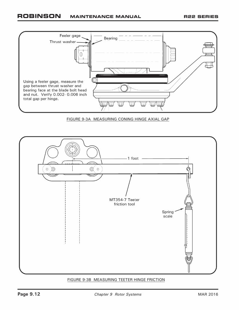
FIGURE 9-3A MEASURING CONING HINGE AXIAL GAP
FIGURE 9-3B MEASURING TEETER HINGE FRICTION
Page 9.12 Chapter 9 Rotor Systems MAR 2016

MAR 2016 Chapter 9 Rotor Systems Page 9.13
9.123 Main Rotor Hub Journal and Shim Calculations (continued)
B. Coning Hinge Calculation (continued)
A154-1 Hub:
1. Measure main rotor hub width across the coning hinge bearing faces: in.
2. Subtract measured width of blade spindle at coning hinge bolt hole: – in.
Calculated empty space: = in.
CAUTION
Initial coning hinge hardware stack-up must be adjusted to 0.003/0.006 inch greater than calculated empty space. A smaller initial stack-up could damage thrust washers and hub bearings during installation.
3. To accommodate dimensional change due to clamping force, add: + 0.003/0.006 in.
Sum: =/
in.
4. Select a combination of A106-1, -2, -3, or -6 journals whose combined measured lengths equal Sum. The same journal dash number must be used under the head of both coning hinge bolts to maintain symmetry.
5. Adjust journal combination as required to meet coning hinge axial gap requirement per Figure 9-3A and to maintain teeter friction requirement as follows: It must be possible to manually cone each blade without teetering the hub when blades are held up off the droop stops and lifted at tip.
9.124 Adjusting Hinge Friction
A. Teeter Hinge Friction Adjustment
1. Remove main rotor blades per § 9.111.
2. Refer to Figure 9-2A and Table 9-1. Remove cotter pin, nut, thrust washer, and nut-side A117 shims. Adjust teeter hinge friction by changing nut-side shim stack thickness in small increments; reducing shim stack thickness increases friction, increasing shim stack thickness reduces friction. Install shims, thrust washer, and nut.
3. Refer to Figure 9-3B. While torquing teeter hinge bolt per § 1.330, check teeter hinge friction frequently. To check friction, install MT354 teeter friction tool into coning hinge bearings on one side of main rotor hub and measure moving force (not breakaway force) required to teeter main rotor hub with a spring scale. Teeter friction must be less than 15 ft-lb.
4. Install a new bolt and nut per § 9.122.

9.124 Adjusting Hinge Friction (continued)
B. Coning Hinge Friction Adjustment
1. Refer to Figure 9-2B and Table 9-1. Remove cotter pin, nut, thrust washer, and cone blade to remove nut-side journal.
a. B370-1 Hub: Adjust coning hinge friction by changing trailing-edge shim stack thickness in small increments; reducing shim stack thickness increases friction, increasing shim stack thickness reduces friction. Coning hinge friction is zero when there is a measurable axial gap per Figure 9-3A. Install shims, thrust washer, and nut.
b. A154-1 Hub: Adjust coning hinge friction by changing trailing-edge journal length in small increments; using a shorter journal increases friction, using a longer journal reduces friction. Coning hinge friction is zero when there is a measurable axial gap per Figure 9-3A. Install journal, thrust washer, and nut.
2. Install a new bolt and nut per § 9.122, steps 5 thru 7. Repeat steps for opposite blade.
3. Check coning hinge friction by lifting blades until spindle tusks clear droop stops. Hold one blade level and cone opposite blade. Rotor hub must not teeter as blade is coned. Repeat check on opposite blade.
4. Using a feeler gage, measure gap between thrust washers and bearing faces at coning hinge bolt head and nut. Verify 0.002-0.006 inch total gap per hinge.
5. Drill nut and bolt per § 9.116. Install a new cotter pin wet with epoxy primer.
9.125 Shifting the Main Rotor Hub
1. Remove cotter pin, nut, thrust washer, and nut-side A117 shims.
2. Have two people cone the main rotor blades. Push out teeter hinge bolt with another bolt.
3. Move or exchange existing shims from one side of hub to the other as indicated by main rotor balance chart (refer to § 10.230).
4. Install teeter hinge bolt per § 9.122.
Page 9.14 Chapter 9 Rotor Systems MAR 2016

9.126 Main Rotor Hub Bearing Replacement
1. Remove main rotor hub per § 9.121.
2. Refer to Figure 9-4. Verify tooling surfaces are smooth to avoid damaging hub and bearings. Press A648-1 and/or A648-3 bearing(s) from hub using MT329-1 plug assembly (Rev H or subsequent) with MT329-10 tube. Press A648-2 bearing(s) from hub using MT329-11 plug assembly with MT329-10 tube.
3. Visually inspect hub bearing bore and verify no scoring or scratches. Polish out fretting or corrosion to 0.0005 inch maximum depth (1.1870 inch maximum bore diameter, or 1.3120 inch maximum bore diameter [B370-1 hub coning hinge bearing bores]) and 0.25 inch minimum blend radius using 320-grit or finer wet-or-dry sandpaper. Fretting or corrosion that extends beyond repair limit requires hub replacement.
NOTE
Do not allow epoxy primer to contact bearing’s Teflon liner.
4. Verify bearing mating surfaces are smooth and clean and apply light coat of epoxy primer (refer to § 1.400). If visible, orient coning hinge bearing’s Teflon liner seam toward top of hub. While primer is wet, press in new A648-1 and/or A648-3 bearing(s) using MT329-1 plug assembly or A648-2 bearing(s) using MT329-11 plug assembly (always use MT329-13 or MT329-2 [A154-4 Hub] support when replacing coning hinge bearing) until bearing flange is completely seated against hub.
5. Using a syringe, seal between bearing’s outboard flange and hub and bearing’s inboard edge and hub with small fillet of epoxy primer.
FIGURE 9-4 MAIN ROTOR HUB BEARING REPLACEMENT
MAR 2016 Chapter 9 Rotor Systems Page 9.15

FIGURE 9-5A MEASURING MAIN ROTOR BLADE DAMAGE
FIGURE 9-5B SCRATCH LIMITS
Page 9.16 Chapter 9 Rotor Systems MAR 2016

9.130 Inspection of Main Rotor Blades
NOTE
Main rotor blades are 14 CFR § 27.602 critical parts. Notify RHC Technical Support when voids exceeding the limits specified in the instructions below are found, providing blade serial number, helicopter serial number, time in service for the rotor blade, and location and size of the voids that exceed the limits.
NOTE
The inspection criteria in this section applies to blade damage that occurs after blade manufacturing (including shipping and handling and time in service). Damage after blade manufacturing usually exhibits paint scuffing, scratches, or freshly-exposed metal in the form of scratches in the finish. If a blade manufacturing irregularity is suspected, contact RHC Technical Support.
CAUTION
A blade may be repaired more than one time. However, in no case can more than the maximum material be removed or the maximum dent depth be exceeded in any one location.
A. Measuring Damage
1. Refer to Figure 9-5A. Measure blade damage using a straight edge and a thickness gage. Keep straight edge parallel with the leading and trailing edges.
2. If blades are installed on the helicopter, measure damage using the shortest straight edge possible to span damaged area. Using a straight edge of excessive length will cause a false reading due to natural droop of the blade.
B. Measuring Material Removed After Repair
1. Use calipers or micrometers and compare measurements before and after repair to estimate amount of material removed.
2. Use a straight edge and thickness gage to measure repaired areas less than 2 inches across in the blade skins and spar.
9.131 Scratches and Corrosion on Blade Skins and Doublers
1. Refer to Figure 9-5B. Damage may not exceed the following limits after rework:
A016-6 Blades:a. 0.004 inch maximum depth for scratches more than 15º from spanwise axis.b. 0.006 inch maximum depth for scratches less than 15º from spanwise axis.
A016-4 Blades:a. 0.002 inch maximum depth for scratches more than 15º spanwise.b. 0.003 inch maximum depth for scratches less than 15º spanwise.
2. Refer to § 9.140 for repair procedures for damage within limits. Polish out scratches and corrosion greater than 0.0005 inch deep using a 0.10 inch blend radius.
OCT 2014 Chapter 9 Rotor Systems Page 9.17
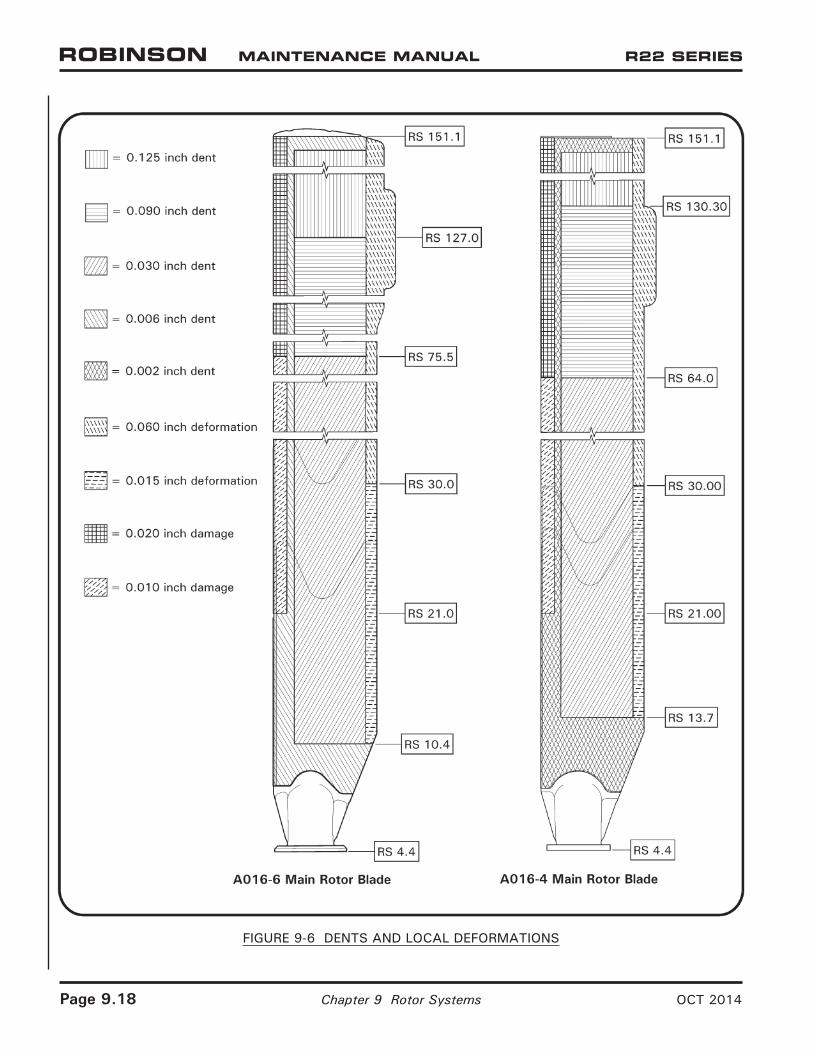
FIGURE 9-6 DENTS AND LOCAL DEFORMATIONS
Page 9.18 Chapter 9 Rotor Systems OCT 2014

9.132 Dents and Local Deformations
CAUTION
Tap-test dented areas in honeycomb using an AN970-4 washer or 1965-or-later U.S. quarter dollar coin in good condition. If any voids are found associated with dents, contact RHC Technical Support.
CAUTION
Do not repair any dent that has a sharp cut or break in the skin; dent must have 0.060 inch minimum bottom radius. If necessary, locally penetrant inspect, keeping penetrant materials away from bond joints.
1. Refer to Figure 9-6. Damage may not exceed the following limits:
a. Honeycomb:
A016-6 Blades:
i. 0.020 inch maximum bulge on opposite side of blade, opposite dent.ii. 0.125 inch maximum depth dent between RS 127.0 and RS 151.1.iii. 0.090 inch maximum depth dent between RS 75.5 and RS 127.0.iv. 0.030 inch maximum depth dent between RS 10.4 and RS 75.5.
A016-4 Blades:
i. 0.020 inch maximum bulge on opposite side of blade, opposite dent.ii. 0.125 inch maximum depth dent between RS 130.30 and RS 151.1.iii. 0.090 inch maximum depth dent between RS 64.00 and RS 130.30.iv. 0.030 inch maximum depth dent between RS 13.7 and RS 64.00.
b. Leading edge of doublers:
A016-6 Blades: 0.010 inch maximum depth dent.
c. Supported bond joints:
A016-6 Blades: 0.006 inch maximum depth dent.
A016-4 Blades: 0.002 inch maximum depth dent.
d. Local deformations:
A016-6 Blades: Within 0.75 inch forward of trailing edge:
i. 0.060 inch deformation between RS 30.0 and RS 151.0.ii. 0.015 inch deformation between RS 10.4 and RS 30.0.
A016-4 Blades: Within 0.75 inch forward of trailing edge:
i. 0.060 inch deformation between RS 30.00 and RS 151.00.ii. 0.015 inch deformation between RS 13.70 and RS 30.00.
OCT 2014 Chapter 9 Rotor Systems Page 9.19

FIGURE 9-7 ROOT FITTING BLEND LIMITS
Page 9.20 Chapter 9 Rotor Systems OCT 2014
9.132 Dents and Local Deformations (continued)
1. e. Spar: Refer to step 2. Blend damaged areas by hand with a minimum 1.0 inch blend radius. Blending is not allowed within 0.010 inch of spar groove leading edge.
A016-6 Blades:
i. 0.020 inch maximum depth damage between RS 75.5 and RS 151.0.ii. 0.010 inch maximum depth damage between RS 21.0 and RS 75.5.A016-4 Blades:i. 0.020 inch maximum depth damage between RS 64.0 and RS 151.0.ii. 0.010 inch maximum depth damage between RS 21.00 and RS 64.00.
2. Refer to § 9.140 for repair procedures for damage within limits. Smooth, round bottom dents with 0.060 inch minimum radius may be filled and faired to an aerodynamic shape.
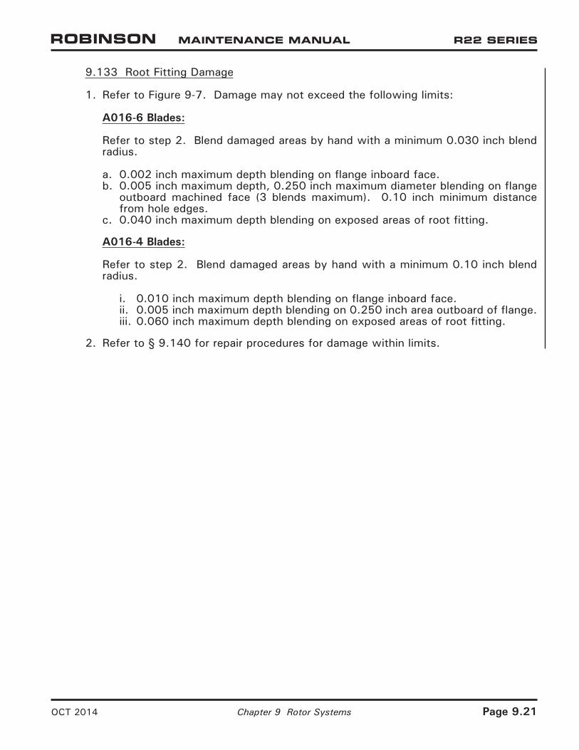
9.133 Root Fitting Damage
1. Refer to Figure 9-7. Damage may not exceed the following limits:
A016-6 Blades:
Refer to step 2. Blend damaged areas by hand with a minimum 0.030 inch blend radius.
a. 0.002 inch maximum depth blending on flange inboard face.b. 0.005 inch maximum depth, 0.250 inch maximum diameter blending on flange
outboard machined face (3 blends maximum). 0.10 inch minimum distance from hole edges.
c. 0.040 inch maximum depth blending on exposed areas of root fitting.
A016-4 Blades:
Refer to step 2. Blend damaged areas by hand with a minimum 0.10 inch blend radius.
i. 0.010 inch maximum depth blending on flange inboard face.ii. 0.005 inch maximum depth blending on 0.250 inch area outboard of flange.iii. 0.060 inch maximum depth blending on exposed areas of root fitting.
2. Refer to § 9.140 for repair procedures for damage within limits.
OCT 2014 Chapter 9 Rotor Systems Page 9.21

FIGURE 9-8 BOND AREAS
Page 9.22 Chapter 9 Rotor Systems OCT 2014

OCT 2014 Chapter 9 Rotor Systems Page 9.23
9.134 Voids
CAUTION
Tap-test voids and debonds in blades using an AN970-4 washer or 1965 or later U.S. quarter dollar coin in good condition.
CAUTION
Voids or debonds in doublers are not field repairable. If voids or debonds are detected in doublers which exceed limits, contact RHC Technical Support.
A. Critical Bond Areas
Refer to Figure 9-8. Critical bond areas are areas less than 0.50 inch spanwise and less than 0.30 inch chordwise from the edge of any structural bond joint.
Bond areas not defined as semi-critical or non-critical are considered critical.
Voids separated by less than 0.25 inch are considered continuous.
1. Damage may not exceed the following limits:
a. 0.10 square inch maximum void.b. Area must be at least 90% bonded.
B. Semi-Critical Bond Areas
A016-6 Blades:
A016-6 Blades do not have semi-critical bond areas.
A016-4 Blades:
Refer to Figure 9-8. Semi-critical bond areas are areas more than 0.50 inch spanwise or more than 0.30 inch chordwise from the edge of the trim tab.
Voids separated by less than 0.25 inch are considered continuous.
1. Damage may not exceed the following limits:
a. 0.80 inch diameter circle maximum void.b. 0.90 square inch maximum void.c. 0.10 square inch maximum of a void extending into a critical bond area.d. Area must be at least 80% bonded.
C. Non-Critical Bond Areas
Refer to Figure 9-8. Non-critical bond areas are areas more than 0.50 inch spanwise or more than 0.30 inch chordwise from B440 cap (A016-4 blades), from doubler edges, and from bonded areas between skin and honeycomb.

Page 9.24 Chapter 9 Rotor Systems OCT 2014
9.134 Voids (continued)
C. Non-Critical Bond Areas (continued)
A016-6 Blades:
1. Voids in doubler bond joints separated by less than 0.25 inch are considered continuous. Damage in doubler bond joints may not exceed the following limits:
a. Area must be at least 80% bonded.b. 5.0 square inches, 1.0 inch chordwise, & 6.0 inches spanwise maximum void.c. 0.10 square inch maximum of a void extending into a critical bond area.d. Voids are permissible within 0.30 inch of doubler leading edge where it
wraps around spar and root fitting.
2. Voids in honeycomb bond joints separated by less than 0.50 inch spanwise or 1.0 inch chordwise are considered continuous. Damage in honeycomb bond joints may not exceed the following limits:
a. Area must be at least 80% bonded.b. 8.0 square inches, 1.0 inches chordwise, & 20.0 inches spanwise maximum
void inboard of RS 92.0.c. 14.0 square inches, 2.0 inches chordwise, & 20.0 inches spanwise maximum
void outboard of RS 92.0.
A016-4 Blades:
1. Voids in A934 doubler bond joints may not exceed the following limits:
a. 5.0 square inches, 1.10 inches chordwise & 6.0 spanwise maximum void.b. 0.10 square inch maximum void extending into a critical bond area.c. 2.0 inches maximum void from outboard tips (refer to R22 SL-55).
2. Voids in honeycomb bond joints inboard of RS 106.0 may not exceed 8.00 square inches, 1.00 inches chordwise, & 20.00 inches spanwise maximum.
3. Voids in honeycomb bond joints outboard of RS 106.0 may not exceed 14.00 square inches, 2.00 inches chordwise, & 20.00 inches spanwise maximum.
4. Voids in honeycomb bond joints between RS 120.0 and RS 133.5, and between RS 150.0 and 166.0, must be at least 1.0 inch forward of honeycomb trailing edge and the skin over void may not move when trim tabs are flexed.
5. Voids in A934 doubler bond joints separated by less than 0.25 inch, less than 0.50 inch spanwise, or less than 1.0 inch chordwise are considered continuous. Area must be at least 80% bonded.

9.140 Repair of Main Rotor Blades
Refer to § 1.400 for approved materials.
CAUTION
Do NOT use power tools or chemical paint strippers to repair main rotor blades.
1. Measure damage per § 9.130.
2. Remove damage at trailing edges, trim tab edges, tip cap, and/or tip corner by trimming per § 9.141 as required.
3. Polish out damage using 220 grit or finer wet-or-dry aluminum-oxide or silicon-carbide abrasive paper, and finish with 320 grit or finer wet-or-dry abrasive paper. A fine-toothed file may be used along the spar and trailing edge, provided the area is finished with 320 grit or finer wet-or-dry abrasive paper. Sand or file in spanwise direction. Remove only the material necessary to remove the damage and blend to the radius or dimension specified. Visually inspect and verify damage is removed.
4. Measure material removed per § 9.130. Verify repair does not exceed limit specified.
5. Seal or fill as required per the following:
a. Clean area to be sealed or filled using approved solvent (refer to § 1.400).
b. Apply epoxy primer to bond joints with pin holes or other openings. Mix primer per manufacturer’s instructions. Allow a minimum of 24 hours cure time.
c. Using 220-grit or finer wet-or-dry aluminum-oxide or silicon-carbide abrasive paper, hand-sand cured adhesive in spanwise direction to a smooth, aerodynamic finish, congruent with the blade airfoil. Do not remove metal.
d. Hand-sand surrounding painted surface until 25% primer remains. Keep bare metal to a minimum.
6. Paint per § 9.142 as required.
7. Track and balance main rotor per § 10.230 as required.
OCT 2014 Chapter 9 Rotor Systems Page 9.25

FIGURE 9-9A TRIM LIMITS
Page 9.26 Chapter 9 Rotor Systems OCT 2014

9.141 Trimming
Refer to Figures 9-9A & 9-9B. Trimming may be performed on the trailing edge of main rotor blade skins and trim tab edges within limits shown. (Alternately, a trailing edge nick or notch may be blended out 1.0 inch minimum spanwise, each side of nick or notch within limits shown.) Trimming is not permitted on spar or doublers.
Tip cap and tip corner may be trimmed within limits shown.
Finish repair per § 9.140 steps 2 thru 7. File trailing edge or trim tab edges square with skins (do not file into a point). Verify minimum chord dimension.
9.142 Painting
Refer to § 1.400 for approved materials. Refer to paint manufacturer’s recommendations.
CAUTION
If force-drying paint, do not exceed 175º F surface temperature on blade; monitor blade temperature.
1. Remove main rotor blade tip cover(s) as required. Clean the blade(s).
2. Feather edge of paint bordering bare metal by hand-sanding spanwise with 220-grit or finer wet-or-dry aluminum-oxide or silicon-carbide abrasive paper. Do not remove metal.
3. Mask area to prevent overspray contamination.
4. Clean bare metal to be painted with a lint-free cloth dampened with enamel cleaner.
5. Prime bare metal, including bare metal under tip cover(s) as required, with at least two coats epoxy primer. Scuff first coat of primer with 320-grit abrasive paper (or very fine Scotch-Brite), and wipe down with a lint-free cloth dampened with enamel cleaner prior to applying second coat.
FIGURE 9-9B FILING SKIN EDGES SQUARE
OCT 2014 Chapter 9 Rotor Systems Page 9.26A

FIGURE 9-10 MAIN ROTOR BLADE PAINT SCHEME (A016-6 BLADE SHOWN)
9.142 Painting (continued)
6. Refer to Figures 9-10. Apply dark gray (root), flat black, white, and/or yellow polyurethane enamel, as required, to primed area in accordance with paint manufacturer’s recommendations.
NOTE
Allow Imron paint to cure at least 72 hours before flying in erosive conditions (such as drizzle, rain, or dust).
7. Install blade tip cover(s) if removed.
8. Remove masking materials.
Page 9.26B Chapter 9 Rotor Systems OCT 2014
9.200 Tail Rotor
9.210 Tail Rotor Assembly Removal
1. Mark or tag each pitch link and corresponding blade for reinstallation. Remove hardware securing pitch links to tail rotor blades, noting hardware removed.
NOTE
Tail rotor pitch link-to-blade attach bolts may be different lengths and/or have different washers installed under nut for balancing.
2. Remove nut and A141-14 washer securing A119-1 bumper to tail rotor gearbox output shaft.
3. Remove teeter hinge bolt, then slide tail rotor assembly and bumper, and A130-1 spacers (A030-1 hub assembly only), off of shaft.
OCT 2014 Chapter 9 Rotor Systems Page 9.26C

FIGURE 9-11 TAIL ROTOR ASSEMBLY INSTALLATION (A008-4 ASSEMBLY SHOWN)
Page 9.26D Chapter 9 Rotor Systems OCT 2014


![General Coning Correlations Based on Mechanistic Studiess-skj/CoNing/Lee-R.S/00020742[1].pdf · General Coning Correlations Based on Mechanistic Studies ... The coning of water can](https://img.pdfslide.net/doc/110x75/5aaf501a7f8b9adb688d7e13/general-coning-correlations-based-on-mechanistic-s-skjconinglee-rs000207421pdfgeneral.jpg)