Embed Size (px)
Citation preview

COMPREHENSIVE PAVEMENT DESIGN MANUAL
Chapter 9 - Subsurface Pavement Drainage (Limited Revisions)
Revision 7
May 24, 2018


3/30/2018
CHANGES TO CHAPTER 9 Pages Changes Contents List of Figures and Tables included. 9-5 Section 9.3, first paragraph. References to Permeable Base have been revised to
reflect that Type 1 Asphalt Treated Permeable Base is eliminated and only Type 2 Asphalt Treated Permeable Base will be specified when required.

7/02/02
CHAPTER 9SUBSURFACE PAVEMENT DRAINAGE
Contents Page
9.1 INTRODUCTION . . . . . . . . . . . . . . . . . . . . . . . . . . . . . . . . . . . . . . . . . . . . . . . . . . . . . . . 9-1
9.2 BASIC PAVEMENT DRAINAGE GUIDELINES . . . . . . . . . . . . . . . . . . . . . . . . . . . . . . . 9-1
9.2.1 Drainage Design Issues . . . . . . . . . . . . . . . . . . . . . . . . . . . . . . . . . . . . . . . . . . . . 9-1
9.2.2 Drainage Construction Issues . . . . . . . . . . . . . . . . . . . . . . . . . . . . . . . . . . . . . . . 9-3
9.2.3 Drainage Maintenance Issues . . . . . . . . . . . . . . . . . . . . . . . . . . . . . . . . . . . . . . . 9-4
9.3 NEW CONSTRUCTION EDGEDRAIN SYSTEMS . . . . . . . . . . . . . . . . . . . . . . . . . . . . . 9-5
9.4 RETROFIT EDGEDRAIN SYSTEMS . . . . . . . . . . . . . . . . . . . . . . . . . . . . . . . . . . . . . . . 9-8
9.4.1 Conventional Stone Trench and Pipe Edgedrain . . . . . . . . . . . . . . . . . . . . . . . 9-8
9.4.2 Prefabricated Geocomposite Edge Drain (PGED) . . . . . . . . . . . . . . . . . . . . . . . 9-9
9.5 CROSSDRAINS . . . . . . . . . . . . . . . . . . . . . . . . . . . . . . . . . . . . . . . . . . . . . . . . . . . . . . . 9-11
9.6 REFERENCES . . . . . . . . . . . . . . . . . . . . . . . . . . . . . . . . . . . . . . . . . . . . . . . . . . . . . . . . 9-12
APPENDIX 9A . . . . . . . . . . . . . . . . . . . . . . . . . . . . . . . . . . . . . . . . . . . . . . . . . . . . . . . . . . . 9-13
LIST OF FIGURES
Figure Title Page9-1 Typical Edgedrain Outlet . . . . . . . . . . . . . . . . . . . . . . . . . . . . . . . . . . . . . . . . . . . . . . 9-79-2 Stone Trench Edgedrain Retrofit . . . . . . . . . . . . . . . . . . . . . . . . . . . . . . . . . . . . . . . . 9-89-3 Typical Prefabricated Geocomposite Edge Drain . . . . . . . . . . . . . . . . . . . . . . . . . . . 9-109-4 Plan View of Typical Crossdrain . . . . . . . . . . . . . . . . . . . . . . . . . . . . . . . . . . . . . . . . 9-11

SUBSURFACE PAVEMENT DRAINAGE 9-1
6/30/00
9.1 INTRODUCTION
This chapter includes guidance on the design of edgedrain and underdrain systems to providepositive drainage for pavements. This chapter covers subsurface drainage systems only. Fordesign information about surface drainage such as open channels, culverts, storm drainagesystems, or hydrology, refer to Chapter 8 of the Highway Design Manual.
Pavement drainage is critical to pavement performance. The NCHRP Synthesis 239, PavementSubsurface Drainage Systems, states that based on a national survey, drained and maintainedpavements last up to twice as long as undrained pavements. It also found that maintenance andoverlays do not greatly improve the life of pavements that do not have good subsurface drainage.
Because there is no way of stopping water from infiltrating the pavement surface, removal of thatwater is essential to extending the life of the pavement. The main purpose of subsurface drainageis to remove water as quickly as possible. When granular layers beneath a flexible pavementsurface become saturated with water and are not allowed to drain, they become weak. Since thegranular layer is a structural component of a flexible pavement system, this weakens the entirestructure, causing higher than average damage from each vehicle load (i.e., premature failure). Forrigid pavements, water trapped beneath slabs may lead to pumping at the joints and loss of material(voids) beneath the slab. This in turn may lead to loss of support and premature failure of thepavement.
This chapter supersedes conflicting information in the Highway Design Manual, which has not beenaltered at the time of this printing of this manual, specifically HDM Chapter 3, Sections 3.2.4.6,3.3.5, and Chapter 9, Section 9.3.9.
9.2 BASIC PAVEMENT DRAINAGE GUIDELINES
9.2.1 Drainage Design Issues
Underdrains are perforated or porous pipes, installed in narrow trenches and surrounded bycrushed stone or underdrain filter material that is both pervious to water and capable of protectingthe pipe from infiltration by the surrounding soil. They are used to lower the groundwater level,drain slopes, prevent ground water from entering the pavement, and remove surface water thatenters the pavement.
Edgedrains, on the other hand, primarily serve to remove surface water that enters the pavement.Often the terms underdrains and edgedrains are used interchangeably, since they both drain thepavement and are located at the edge of the pavement. The edgedrain systems discussed in thischapter mainly serve to remove surface water, but since they also drain the area below thesubgrade surface they act as underdrains.
While edgedrains help to lower perched water tables below the pavement, they can also becomestorage zones for water if the water table is seasonally or annually high. Thus, a saturatededgedrain run provides a good source of water for frost lense formation below the pavement during the winter and spring months. For this reason, the edgedrain should only be placed at an elevationabove the seasonally high water tables or the profile of the road should be raised. The typical depth

SUBSURFACE PAVEMENT DRAINAGE9-2
7/02/02
of the edgedrain is 300 mm below the subbase, with the edgedrain pipe invert 200 mm below thesubbase.
Edgedrains or underdrains may be installed without pipes, however the stone and pipe combinationis preferred since it gives protection against the pipe becoming crushed during construction orclogged during use, since the water can freely flow through either the stone or the pipe. The outlettrench should always use a stone and pipe combination, so it will quickly disperse water from theedgedrain.
After a period of time the underdrain filter material (crushed stone) becomes a natural filter for theunderdrain and a geotextile is not necessary. However, there may be instances where a geotextileshould be used to wrap the underdrain or edgedrain trench, such as fine silty subgrade soil or otherpoor subgrade soil conditions. The designer should contact the Regional Geotechnical Engineer/for guidance on selecting drainage geotextiles based on the current version of Geotechnical/Engineering Bureau Directive, 124.1-4-2R**, “Geosynthetic Acceptance and Quality Assurance/Procedures” (see Geotechnical Engineering Bureau’s Home Page). The Department’s Approved/List of Geosynthetics for Highway Construction (also on NYSDOT’s WEB) contains a listing of thecurrently approved drainage geotextiles. More detailed design procedures are found in FHWAPublication HI-95-038, Revised 1998, NHI Course No. 13213, Geosynthetic Design andConstruction Guidelines - Participant Notebook.
Because subbase material is well graded for maximum strength, it is considered to be impermeablecompared to the permeable base layer, so water tends to accumulate on the subbase surface.Since a permeable base layer is used in new construction projects, all runoff that enters thepavement section should drain quickly to the edgedrain and then to the outlets. Water that cannotbe absorbed into the subbase or exit through the edgedrains will pool in the permeable base layeror the bound layers above and become a bathtub section, causing premature road distress.
Locate outlets and shallow pipes well away from areas of expected future surface maintenanceactivities such as sign replacement and catch basin clean out or repair.
Information about drainage ditches is covered in HDM Chapters 3 and 8. If ditches and mediansare too shallow to outlet the edgedrain system, or ditches do not exist, there are several outlettingoptions which are listed below.
1. Storm water drainage system. In these cases subsurface drainage design should becoordinated with surface drainage design (Chapter 8, HDM). The storm water inlet must be lowenough and large enough to accept the inflow of the edgedrain without backing up. FHWArecommends that the edgedrain inlet be at least 150 mm above the 10-year storm flow line inthe drainage structure.
2. Dry well. Outlet to a dry well if a storm water system is not possible. The dry well is essentiallyanother edgedrain system outside the pavement structure built to temporarily store and releasewater. The dry well is a trench 300 mm wide by a minimum of 900 mm deep. They arebackfilled with underdrain filter material to within 150 mm of the surface (see Section 9.3, item 3), covered with a geotextile underdrain material, then backfill with excavated material. The drywell should always be outletted to a ditch or other outlet. Onlyuse this option if the dry well is above the water table.
3. Raise the grade and create ditches. If practical, low lying sections and dips should be raised.

SUBSURFACE PAVEMENT DRAINAGE 9-3
6/30/00
4. Daylight the permeable base layer. If the road is built on an embankment with ditches, thepermeable base layer may be daylighted. This should be done for cases when outletting isdifficult, and maintenance is unlikely. Refer to Section 9.3, Permeable Base layer.
5. Do not use a drainage system. For sections where outletting is not possible and the roadcannot be raised, no permeable base layer or edgedrain should be used. Water will saturatethe edgedrain and drainage layer possibly creating frost lenses in the pavement during thewinter and spring months. It is better to have no drainage than a bathtub section.
On steep downgrades or side hill locations where there could be a heavy flow of water through thepavement, either crossdrains or more closely spaced drainage outlets may be needed. Crossdrainsmay also be needed to support outlets at discontinuities in the roadway, such as bridges, culverts,and large utilities. Refer to Section 9.5 of this chapter for more information about crossdrains.
Outlet markers should be installed to designate the location of outlets for future maintenancecleanouts. If maintenance personnel cannot find the outlets, no maintenance can be performed.These markers may be: metal or plastic marker post placed on the slope at the outlet or placedclear of the shoulder; or special plant groupings placed above the outlet locations. These outletsshould be located behind the design clear area, at the right of way line, or behind the guiderail.Refer to Appendix 5B for the current outlet marker specification to use (this specification may notbe available at the time of this printing.)
9.2.2 Drainage Construction Issues
All drainage designs should be reviewed for constructibility. The following construction problemsalong with a suggested solution, should be considered when designing the drainage system:• Poor grades can leave water pooled in the pipes (check drainage profiles).• Guiderail and sign posts driven through drains (show guiderail and post locations on typical
sections).• Pipes and other parts of the system crushed and collapsed during construction (include video
inspection).• Inadequate or altered drainage outlet spacings (specify outlet spacing on plans).• Bad or poor headwall connections (include outlet details as shown in Appendix 9A).• Improper use of connectors such as T-connectors used on grades (include connection details
as shown in Appendix 9A).• High ditch lines that do not allow proper drainage from outlets (include outlet location table).• Outlets that have been left out altogether (check outlet locations and include outlet location
table).• Deep ditch lines that drain well but are not traversable or trap vehicles (check HDM Ch.10 for
typical section guidance).
Drainage inspection should be included on all projects. Once the pavement is finished, it will bedifficult to repair or replace the drainage system and the pavement life may be reduced. Drainageinspection may include either using video inspection or simply pouring water on the drainage layerand checking the outflow. Video inspection involves sending a video probe into the outlet end andinspecting the edgedrain and outlet for discontinuities or problems. Refer to Appendix 5B for the
SUBSURFACE PAVEMENT DRAINAGE9-4
6/30/00
current video inspection item and guidelines. The second method can be done by pouring a largevolume of water (50 to 100 gallons) onto the permeable base, but must be specified in thespecifications or noted in the plans.
Maintaining an open drainage aggregate is critical during the remaining construction period. Ashovelful of fines can clog the drain. The drainage system should be protected from fouling untilthe pavement section is complete. If a contamination problem is anticipated, geotextile can beplaced over the edgedrain to catch fines: this should be shown in the edgedrain details.
9.2.3 Drainage Maintenance Issues
A well designed and constructed drainage system will not perform properly without adequatemaintenance. Realistically though, drainage systems will receive little or no maintenance over thelife of the pavement, so they should be designed to last as long as possible and to be asmaintenance free as practical. By the time pavement distress is identified, the subgrade andsubbase usually have already failed and the problem cannot be corrected without removing thepavement. A poor design can be corrected during construction if a deficiency is recognized, butmaintenance can seldom correct a poor design.
The combination of vegetative growth, debris, and fines discharging from the edgedrains caneventually plug the outlet pipe. Rodent nests, mowing clippings, and sediment collecting on rodentscreens at the headwalls are common maintenance problems. However, outlets often cannot belocated or maintained because they are hidden by vegetative growth. The use of outlet markers willalleviate this problem .
Inadequately designed outlet aprons will be rutted easier when mowers travel over them duringsaturated conditions, blocking the outlet. Some outlets are so plugged that water gushes from thepipes when the obstructions are removed. Therefore, make sure the outlets are adequatelydesigned as shown in Appendix 9A.
When flexible tubing is used for edgedrains, the pipe will not be perfectly straight. The pipe maybecome clogged by sediment resulting in slow flow, clogged outlet conditions, or sags in the grade.If the grade is 1 percent or less, consider using solid walled edgedrain pipe. Refer to Section 9.3for further guidelines and Appendix 5B for the current item number.
Maintaining drainage systems involves cleaning outlets, replacing rodent screens, flushing orreplacing outlet pipes, repairing damage, and cleaning ditches. See Chapter 10 of this manual formore information about drainage maintenance.
9.3 NEW CONSTRUCTION EDGEDRAIN SYSTEMS
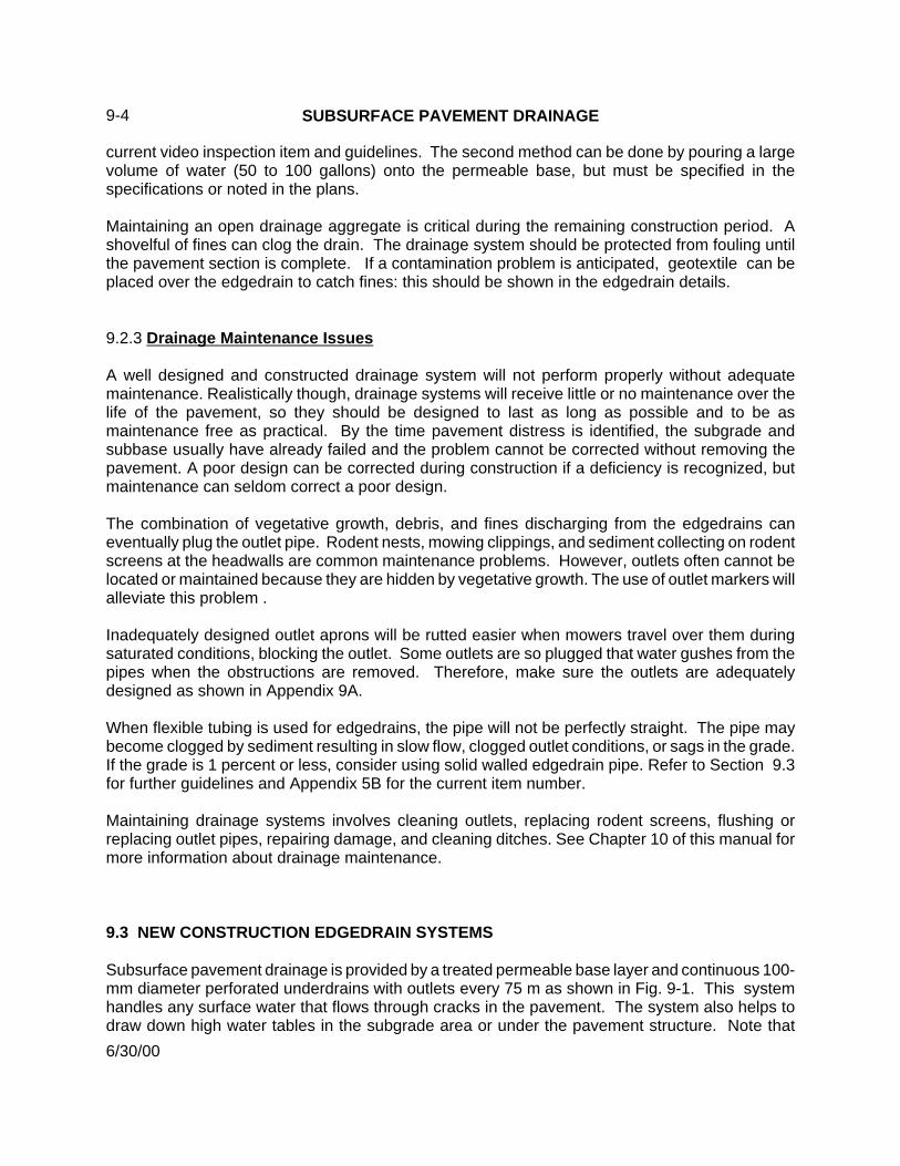
Subsurface pavement drainage is provided by a treated permeable base layer and continuous 100-mm diameter perforated underdrains with outlets every 75 m as shown in Fig. 9-1. This systemhandles any surface water that flows through cracks in the pavement. The system also helps todraw down high water tables in the subgrade area or under the pavement structure. Note that

SUBSURFACE PAVEMENT DRAINAGE
3/30/2018
5
conventional pavement designs (non ESAL-based designs) do not normally have a permeable base
layer.
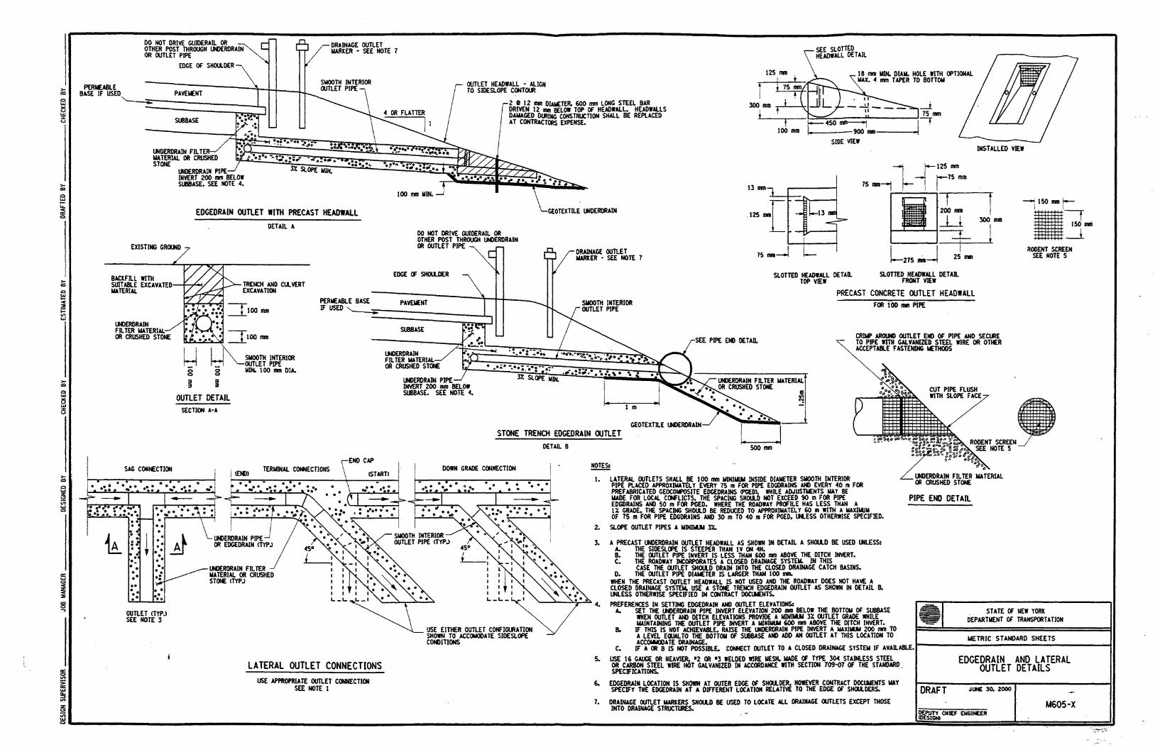
Construction installation details for these edgedrain systems are shown in the draft Standard Sheet
M605-2, Edgedrain and Lateral Outlet Details, which is shown in Appendix 9A. Many of these
construction details are also repeated in Fig. 9-1.
Edgedrains should be placed continuously along both shoulders for all permeable base installations
except in areas where the permeable base is daylighted (see Permeable Base Layer discussion
below). If one shoulder is on a high side of the road, such as banked curves or ramps, edgedrains
are not needed on the high side of the road. In those locations, the subbase and permeable base
layers on the high side of the road should either slope towards the low side of the road, or be
daylighted onto the banked curve.
Edgedrains and/or permeable base may not be necessary in locations that have well drained soil.
Contact the Regional Geotechnical Engineer early in the project development (scoping stage) for
evaluation of soil conditions and further edgedrain recommendations.
For pipe edgedrains the lateral outlets should be spaced approximately every 75 meters in
accordance with draft Standard Sheet M605-2, Edgedrain and Lateral Outlet Details, in Appendix
9A. While adjustments may be made for local conflicts, the spacing should not exceed 90 meters.
Where the roadway profile has less than a 1% grade, reduce the spacing to approximately 60
meters, with a maximum spacing of 75 meters. To facilitate the insertion of cleaning equipment,
use 45 bends between the edgedrains and the straight lateral outlet runs.
The edgedrain system consists of the five elements shown in Figure 9-1 and discussed below:
1. Permeable Base Layer. This is a free-draining bound layer, capable of draining both surface
water and preventing water accumulation from the subbase below. The flow of water through
this layer is retarded only by the cross-slope and any obstructions. Type 2 Asphalt Treated
Permeable Base (ATPB) is the only treated permeable base allowed and is used only with
HMA pavements. There may be cases where the Treated Permeable Base material cannot be
placed either due to space limitations for the equipment or intrusion of utilities into the
permeable layer. In these areas, an unbound material, such as open-graded subbase item or a
crushed stone item may be substituted. Contact the Regional Geotechnical Engineer for
further guidance.
Although limited construction traffic is allowed on the treated permeable base, it should not be
used as a haul road. Care should be taken to prevent damage from vehicles turning and carrying
in fines, overly heavy loads, or traffic too soon after rain.
Only in cases where no construction traffic is allowed on the completed permeable base layer,
(side-load trucks), may an untreated permeable base course, such as an open subbase, be used
(listed in Appendix 5B).
The permeable base layer may be daylighted at 3% to the slope face in cases where there is
well drained subgrade (such as silty sand soil found in parts of Region 10), when outlets cannot

SUBSURFACE PAVEMENT DRAINAGE9-6
7/02/02
be used, for flat grades (1% or less), or on the high side of a super-elevated section that isbeing drained to the high side. However, this should not be made the standard treatment sinceit is difficult to maintain a daylighted layer. If this is the case edgedrains and outlets are notneeded. Make sure the bottom of the permeable layer is at least 600 mm above the ditchinvert. This is to prevent silty material or storm water in ditches from entering the pavementstructure and blinding the permeable base layer with topsoil and vegetation.
2. Edgedrain Pipe. This is a perforated pipe which carries the water to the outlets and is centeredin the outlet trench, with the pipe invert 100 mm above the trench bottom. The pipe diameteris typically 100 mm in diameter although for certain high flow situations and combinededgedrain/drainage systems, a 150 mm pipe diameter may be necessary. Perforatedcorrugated polyethylene underdrain tubing or optional underdrain pipe are normally used. Thepipe, along with the trench, should follow the longitudinal grade of the road. If the grade is 1%/or less for extended lengths, consider using a rigid smooth-walled PVC underdrain pipe to/promote faster drainage, and/or providing more outlets at closer spacing. Refer to Appendix/5B for the current item numbers./
3. Underdrain Filter Material. This material is placed around the edgedrain and outlet pipes in a300 mm by 300 mm trench for 100 mm pipe or a 350 mm by 350 mm trench for 150 mm pipe.For excavation, use item 206.02 M, Trench and Culvert Excavation. For other pipe sizes usea trench 200 mm wider than the pipe diameter. When no pipe is used specify a minimum 300mm wide trench. Type I or Type II Underdrain Filter is typically used. Type I is preferred, butType II should be used if in direct contact with a fine-grained subgrade. To reduce the expenseof stockpiling requirements crushed stone, screened gravel, crushed gravel or crushed slagmay be used. Designate on the plans either combinations of size Nos. 1, 2, and 3 or specifyType CA-2 coarse aggregate. Recycled glass may also be used. Place the underdrain filtermaterial around and over the underdrain pipe to such a depth that, after compaction, the filtermaterial extends up to the bottom of the permeable base layer or to the top of the subbaselayer. If geotextile is used (see Section 9.2.1), show the geotextile wrapped around the trench,but leave the trench exposed to the permeable base layer.
4. Outlet Pipe. This pipe is a double-wall, rigid, smooth perforated pipe that comes in straightlengths. It is better able to resist crushing from mowers and construction equipment thanunderdrain pipe or corrugated steel pipe. (See Appendix 5B for appropriate pipe item number,since the specification for this pipe may not be available at the time of printing of this manual.)The outlet pipe should be connected to the edgedrain with 45° fittings for future maintenanceand to maximize the outlet slope. Slope the outlet pipe a minimum of 3% to the edgedrainoutlet.
SUBSURFACE PAVEMENT DRAINAGE 9-7
6/30/00
Figure 9-1 Typical Edgedrain Outlet
5. Edgedrain Outlet. The edgedrain can terminate into the following three different outlets. Otheroutlet types are feasible as long as they swiftly disperse the surface and subsurface water (seeSection 9.2.1). Selection criteria is listed in the draft of Standard Sheet M605-2 found inAppendix 9A with the current item numbers listed in Appendix 5B. Outlet type and locationsshould be shown on the plans with edgedrain details and an edgedrain outlet location table.Outlet markers should be specified for the precast concrete headwall and stone trench options.
a. Precast Concrete Headwall. The headwall is used in cases where:(1) the side slope is 1Von 4H or flatter, or (2) when the outlet invert is greater than 100 mm above the ditch invert,or (3) when a closed drainage system is not available. Headwalls should be set on a 100mm bed of underdrain filter material, to provide an alternative drainage path should the pipebecome clogged. The surface of the headwall should be slightly recessed below thesurface of the embankment to minimize the chances of being struck by mowing equipment.The 100 mm pipe headwalls are small, they can be hand carried and maneuvered by twopeople. For pipe diameters greater than 100mm use the following outlet options.
b. Stone Trench. If the side slope and invert conditions mentioned above are not met andthere is no closed drainage system, use a stone trench outlet.
c. Closed Drainage System. When a closed drainage system is available, it should beutilized. Most underdrain systems do not expel large quantities of water so the closeddrainage system should handle this water flow. Water flow in underdrains is usually adelayed event after surface runoff is drained so there should be no capacity problems.Edgedrains and their outlet locations may vary to accommodate the closed drainagesystem, although outlet pipes should be sloped a minimum of 3% into the drainage structure(drop inlet, catch basin, etc.).

SUBSURFACE PAVEMENT DRAINAGE9-8
6/30/00
Figure 9-2 Stone Trench Edgedrain Retrofit
9.4 RETROFIT EDGEDRAIN SYSTEMS
Retrofit edgedrains are used for rehabilitation, restoration or maintenance projects that do not haveexisting functioning subsurface drainage systems. Retrofits are effective for pavement that isrelatively young (<15 years old) and has signs of moisture damage, pavements in cut sections, andareas that have adequate ditch depth or means for outlet drainage. Unless guidance is givenelsewhere, contact the Geotechnical Engineer to determine the need for an edgedrain system. Formost retrofit applications the edgedrain is typically placed at the edge of the driving lane under theshoulder. Retrofit edgedrains generally do not use permeable base layers, unless they areretrofitting roads that have existing permeable base layers. Section 9.2, Drainage Guidelines, alsoapplies to retrofit edgedrains. Use the outletting methods described in Section 9.3. The StoneTrench and Pipe Edgedrain is preferred since it has an estimated service life of 10 to 25 years,(compared with 5 to 10 years for a Prefabricated Geocomposite Edge Drain), it has greaterhydraulic capacity and requires fewer outlets.
9.4.1 Conventional Stone Trench and Pipe Edgedrain
Generally the design requirements for these systems in terms of specifications, dimensioning,slope, and outlet spacing should follow those found in the new construction Section 9.3. Thissystem is used for rubblized projects, crack & seat projects, and for other projects where drainage is needed. A typical stone trench and pipe retrofit design is shown in Figure 9-2. For maximumbenefit, the trench should be below the subbase, (shown as 300 mm below subbase in Figure 9-2),however this may not always be practical. Follow the guidelines given in Note (4) of the EdgedrainDetails in Appendix 9A for setting different edgedrain elevations. If the section is curbed, put theedgedrain in front of the curb as shown in Section 3.2.9, Curbs, in the HDM.

SUBSURFACE PAVEMENT DRAINAGE 9-9
6/30/00
9.4.2 Prefabricated Geocomposite Edge Drain (PGED)
Prefabricated Geocomposite Edge Drain (PGED) has found many applications in NYS in recentyears. The primary advantages over conventional pipe in stone edgedrains are speed and easeof installation, which minimize maintenance and protection of traffic. This equates to a much lowerinstalled price. It has some disadvantages which make it a less useful choice in some applications.Therefore, the following usage policy has been formulated.
PGED should not be used in a series of short runs less than 90 m. The installation advantagesovercome this disadvantage only when continuous long runs of the material are placeable.Occasional short runs may be necessary on a project, but the primary usage should be in long,multiple outlet runs.
PGED should not be used where there is a significant possibility of oversize material (plus 100 mm)to be excavated. Thus, very old pavements (built in the 1930s and 1940s) placed directly onsubgrade must be approached with extreme caution. Even newer pavements (1970s) are oftenfound to have material beneath the pavement which will not excavate well using a 100 mm widetrenching wheel.
PGED should not be used next to a pavement that is going to be rubblized. There is concern thatthe concrete fines created by the rubblizing process may blind the fabric on a PGED, while it wouldhave less effect on the filter stone in a conventional drain. Also, the forces involved in rubblizingmay damage the core and the capacity of the PGED.
PGED should not be installed adjacent to pumping concrete slabs that are not to be overlaid. Therocking motion of the slabs under traffic loads pumps fines into the drain, causing blinding of thefabric, resulting in premature failure.
When using PGED in an area of fine-grained subsoils, it is recommended that the underdrain filtermaterial backfill option be specified. This is to prevent a possible blinding problem that may occurusing existing material as backfill.
The underdrain filter material backfill option should be used next to flexible pavement. Inevitably,with a vertical excavation at the edge of pavement in an area requiring edgedrains (presumablywet), some sloughing and loss of material will occur from under the pavement. Flexible pavementwill not bridge this loss of support. The underdrain filter material backfill placed on the pavementside should minimize concerns of this sort.
If underdrain filter material backfill is necessary with a PGED installation, then consideration shouldbe given to using a conventional underdrain/edgedrain of stone filled trench and pipe. The designershould discuss the conditions and needs of the project with the Regional Geotechnical Engineerto determine the most appropriate treatment.
PGED with existing material backfill is most suited to rigid pavements with well controlled subbase(no oversize material) as long as the subgrade soils are not excessively fine-grained. This appliesto a large number of highways built during the busy days of the 1960s and 1970s.

SUBSURFACE PAVEMENT DRAINAGE9-10
6/30/00
Figure 9-3 Typical Prefabricated Geocomposite Edge Drain
It should be realized that due to their depth and nature, PGEDs are not as effective at treatingpavements with high subgrade water contents, frost problems, or pumping slabs that are not to beoverlaid. PGEDs are best used next to pavements where the observed distresses are likely relatedto surface water penetrating the pavement and then not having an outlet. Any other applicationsmust be carefully considered before use.
As always, any underdrain installation should be in contact with the water-bearing layer (bottom ofsubbase, bottom of pavement). Short curve radius situations (usually ramps) make this impossibleas the ditching wheel cannot follow a tight radius and runs away from the edge of pavement.
As with any drain, PGEDs must be outletted. Outlet spacing should be no greater than 35 m andpreferably less in flat (<1% grade) sections. Also, place an outlet at the bottom of any sag verticalcurves. Use outlets shown in draft Standard Sheet M605-2, Edgedrain and Lateral Outlet Details,(in Appendix 9A), following the guidelines of Section 9.3 of this chapter.
Where existing material backfill is used, the PGED should be installed abutting the side of thetrench closest to the centerline of pavement (the inside of the trench). Where underdrain filtermaterial backfill is used, the PGED should be installed abutting the side of the trench farthest fromthe centerline of pavement (the outside of the trench) as shown in Figure 9-3. Refer to Appendix5B for appropriate specification item number.

SUBSURFACE PAVEMENT DRAINAGE 9-11
6/30/00
Figure 9-4 Plan View of Typical Crossdrain
9.5 CROSSDRAINS
Crossdrains or weeps are narrow drains that run transversely or diagonally across the road.Crossdrains can alleviate problem downhill areas where water is seeping through the pavementor where there is an edgedrain only on one side of the road, or for sag areas to drain from one sideto the other. They can be used in new construction or rehabilitation projects. Use of crossdrains,however, should be kept to a minimum since they are a discontinuity in an otherwise uniformpavement section.
The crossdrain should be a 100 mm wide vermeer cut trench, filled with underdrain filter material(see Section 9.3, item 3) and oriented to drain downhill (except in a sag where should beperpendicular to the centerline). This should handle most flow situations. If very heavy flows areexpected or for new construction use a 100 mm pipe (see Section 9.3) in a 300 mm wide stonefilled trench. In either case the trench should extend from 300 mm below the subbase layer to thetop of the subbase layer and paved directly overtop. The downhill end of the crossdrain shouldextend to the edgedrain or may directly outlet, into a ditch, side slope, or into a closed drainagesystem as discussed in the Section 9.3. Extend the uphill end of the crossdrain to the outer edgeof the shoulder or to the edgedrain, if available. Provide a location plan/chart and cross sectiondetail showing the width and depth of the crossdrain in the plans. Appendix 5B has the latest itemnumber for Crushed Stone Weep, which is used as a crossdrain. A typical crossdrain is shown inFigure 9-4.

SUBSURFACE PAVEMENT DRAINAGE9-12
6/30/00
9.6 REFERENCES
AASHTO Guide for Design of Pavement Structures, Washington D.C.: American Associationof State Highway and Transportation Officials, 1993.
Drainage of Asphalt Pavement Structures, Asphalt Institute Manual Series No. 15, September1984.
Participant’s Manual on Construction of Portland Cement Concrete Pavements, FederalHighway Administration Publication No. FHWA-HI-96-027, U.S. Department of Transportation,October 1996.
Participant’s Notebook on Drainable Pavement Systems, Demonstration Project 87, FederalHighway Administration Publication No. FHWA-SA-92-008, U.S. Department of Transportation,March 1992.
Pavement Notebook for FHWA Engineers, Federal Highway Administration Publication No.FHWA-PD-96-037, U.S. Department of Transportation, October 1996.
Pavement Subsurface Drainage Design, Participant Workbook, Federal Highway AdministrationPublication No. FHWA-NHI-99-030, ERES Consultants, April 1999.
Pavement Subsurface Drainage Design, Reference Manual, Federal Highway AdministrationPublication No. FHWA-NHI-99-028, ERES Consultants, April 1999.
Pavement Subsurface Drainage Systems, Synthesis of Highway Practice 239, NationalCooperative Highway Research Program, 1997.
Signore, J.M., and B.J. Dempsey, Accelerated Testing of Separation Layers for Open-GradedDrainage Layers, Final Report, Project C960014, Illinois Transportation Research Center, IllinoisDepartment of Transportation, 1998.
The New York State Thickness Design Manual For New and Reconstructed Pavements,Revision 1, Technical Services Division, New York State Department of Transportation, October31, 1994.
Yu, Thomas H., L. Khazanovich, S.P.Rao, M.I. Darter, H.V. Quintus, Guidelines for SubsurfaceDrainage Based on Performance, Final Report, ERES Consultants, Inc., prepared for NationalCooperative Highway Research Program, August 1999.

SUBSURFACE PAVEMENT DRAINAGE 9-13
6/30/00
APPENDIX 9A
Edgedrain and Lateral Outlet Details(Draft Standard Sheet)