Embed Size (px)
Citation preview
Alberta Infrastructure and Transportation HIGHWAY GEOMETRIC DESIGN GUIDE JANUARY 2008
ROADSIDE FACILITIES F-1
CHAPTER F
CHAPTER F ROADSIDE FACILITIES
TABLE OF CONTENTS
Section
Subject Page
Number
Page Date F.1 VEHICLE INSPECTION STATIONS .................................................................... F-3 April 1995 F.1.1 Introduction..................................................................................................... F-3 April 1995 F.1.2 Class A VIS. ..................................................................................................... F-3 April 1995 F.1.3 Class B VIS....................................................................................................... F-4 August 1999 F.1.4 Class C Mobile VIS ......................................................................................... F-4 August 1999 F.2 HIGHWAY SAFETY REST AREAS........................................................................ F-13 January 2008 F.2.1 Introduction ...................................................................................................... F-13 January 2008 F.2.2 Strategic Framework........................................................................................ F-13 January 2008 F.2.2.1 Policy Document ................................................................................. F-13 January 2008 F.2.2.2 Location Specifications ....................................................................... F-13 January 2008 F.2.2.3 Priority of Construction...................................................................... F-13 January 2008 F.2.3 Categories.......................................................................................................... F-13 January 2008 F.2.3.1 Existing Divided Highways............................................................... F-14 January 2008 F.2.3.2 Future Divided Highways ................................................................. F-14 January 2008 F.2.3.3 Two Lane Highways........................................................................... F-14 January 2008 F.2.4 Spacing .............................................................................................................. F-14 January 2008 F.2.5 Site Evaluation Chart....................................................................................... F-15 January 2008 F.2.6 Typical Layout Design Formulas................................................................... F-15 January 2008 F.2.7 Parking Requirements..................................................................................... F-16 January 2008 F.2.8 Facilities and Services...................................................................................... F-16 January 2008 F.2.8.1 Public Toilets........................................................................................ F-16 January 2008 F.2.8.2 Picnic Tables......................................................................................... F-17 January 2008 F.2.8.3 Waste Receptacles ............................................................................... F-17 January 2008 F.2.8.4 Parking Area/Security Lighting ....................................................... F-17 January 2008 F.2.8.5 Telephones ........................................................................................... F-18 January 2008 F.2.8.6 Fencing.................................................................................................. F-18 January 2008 F.2.8.7 Aesthetics/Landscaping..................................................................... F-18 January 2008 F.2.9 Signage .............................................................................................................. F-18 January 2008 F.2.9.1 Safety Rest Areas ................................................................................. F-18 January 2008 F.2.9.2 Roadside Turnouts .............................................................................. F-18 January 2008 F.2.10 Exit and Entrance Requirements ...................................................... F-18 January 2008 F.3 ROADSIDE TURNOUTS FOR HIGHLOAD/WIDELOAD USE .................... F-41 March 2007
Alberta Transportation
JUNE 2015 HIGHWAY GEOMETRIC DESIGN GUIDE
F-2 ROADSIDE FACILITIES
CHAPTER F
ROADSIDE FACILITIES
LIST OF FIGURES
Figure
Description
Page
Number
F-1.2 Class A Vehicle Inspection Station (Standard Layout and Access on
Divided Highways) .......................................................................................................................................................F-5
F-1.3 Class B Vehicle Inspection Station (Standard Layout and Access on
Undivided Highways) ..................................................................................................................................................F-7
F-1.4a Class C Mobile Vehicle Inspection Station (Standard Layout and Access on
Undivided Highways) ..................................................................................................................................................F-9
F-1.4b Class C Mobile Vehicle Inspection Station (Standard Layout and Access on Undivided
Highways with AADT Less than 1000.) .............................................................................................................. F-11
F-2.1.1 Typical Safety Rest Area on Existing Divided Highways Stage I (Basic) .................................................. F-25
F-2.1.2 Typical Safety Rest Area on Existing Divided Highways Stage II................................................................ F-27
F-2.1.3 Typical Safety Rest Area on Existing Divided Highways Stage III .............................................................. F-29
F-2.1.4 Typical Safety Rest Area on Existing Divided Highways Stage IV .............................................................. F-31
F-2.2.1 Typical Safety Rest Area on Future Divided “Same Side” .............................................................................. F-33
F-2.2.2 Typical Safety Rest Area on Future Divided “Opposite Side” ....................................................................... F-35
F-2.3.1 Typical Safety Rest Area on Two Lane Highways 20-Year AADT >3,000 ................................................ F-37
F-2.3.2 Typical Safety Rest Area on Two Lane Highways 20-Year AADT <3,000 ................................................ F-39
F-2.3.3 Typical Safety Rest Area on Two Lane Highways for Log Haul Routes .................................................... F-41
F-3.1 Roadside Turnouts for Highload / Wideload Use (Near Point of Origin) ................................................ F-45
LIST OF TABLES
Table
Description
Page
Number
F-2.5a Site Evaluation Chart (Blank) .................................................................................................................................. F-20
F-2.5a Site Evaluation Chart (Example)............................................................................................................................. F-21
F-2.5b Site Evaluation Chart Comments (Blank)............................................................................................................. F-22
F-2.5b Site Evaluation Chart Comments (Example) ....................................................................................................... F-23
Alberta Infrastructure and Transportation HIGHWAY GEOMETRIC DESIGN GUIDE APRIL 1995
ROADSIDE FACILITIES F-3
CHAPTER F ROADSIDE FACILITIES
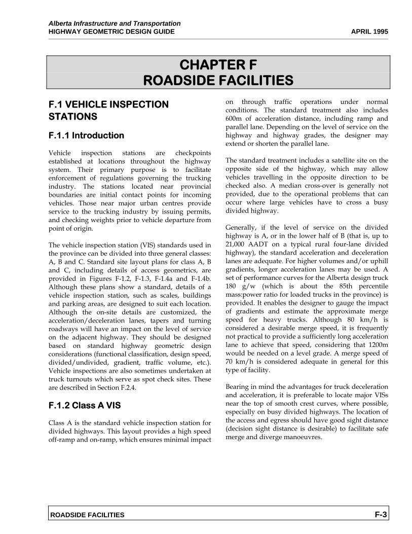
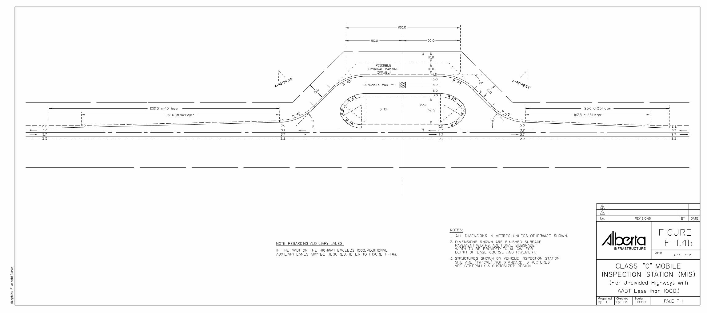
F.1 VEHICLE INSPECTION STATIONS F.1.1 Introduction Vehicle inspection stations are checkpoints established at locations throughout the highway system. Their primary purpose is to facilitate enforcement of regulations governing the trucking industry. The stations located near provincial boundaries are initial contact points for incoming vehicles. Those near major urban centres provide service to the trucking industry by issuing permits, and checking weights prior to vehicle departure from point of origin. The vehicle inspection station (VIS) standards used in the province can be divided into three general classes: A, B and C. Standard site layout plans for class A, B and C, including details of access geometrics, are provided in Figures F-1.2, F-1.3, F-1.4a and F-1.4b. Although these plans show a standard, details of a vehicle inspection station, such as scales, buildings and parking areas, are designed to suit each location. Although the on-site details are customized, the acceleration/deceleration lanes, tapers and turning roadways will have an impact on the level of service on the adjacent highway. They should be designed based on standard highway geometric design considerations (functional classification, design speed, divided/undivided, gradient, traffic volume, etc.). Vehicle inspections are also sometimes undertaken at truck turnouts which serve as spot check sites. These are described in Section F.2.4. F.1.2 Class A VIS Class A is the standard vehicle inspection station for divided highways. This layout provides a high speed off-ramp and on-ramp, which ensures minimal impact
on through traffic operations under normal conditions. The standard treatment also includes 600m of acceleration distance, including ramp and parallel lane. Depending on the level of service on the highway and highway grades, the designer may extend or shorten the parallel lane. The standard treatment includes a satellite site on the opposite side of the highway, which may allow vehicles travelling in the opposite direction to be checked also. A median cross-over is generally not provided, due to the operational problems that can occur where large vehicles have to cross a busy divided highway. Generally, if the level of service on the divided highway is A, or in the lower half of B (that is, up to 21,000 AADT on a typical rural four-lane divided highway), the standard acceleration and deceleration lanes are adequate. For higher volumes and/or uphill gradients, longer acceleration lanes may be used. A set of performance curves for the Alberta design truck 180 g/w (which is about the 85th percentile mass:power ratio for loaded trucks in the province) is provided. It enables the designer to gauge the impact of gradients and estimate the approximate merge speed for heavy trucks. Although 80 km/h is considered a desirable merge speed, it is frequently not practical to provide a sufficiently long acceleration lane to achieve that speed, considering that 1200m would be needed on a level grade. A merge speed of 70 km/h is considered adequate in general for this type of facility. Bearing in mind the advantages for truck deceleration and acceleration, it is preferable to locate major VISs near the top of smooth crest curves, where possible, especially on busy divided highways. The location of the access and egress should have good sight distance (decision sight distance is desirable) to facilitate safe merge and diverge manoeuvres.

Alberta Infrastructur and Transportation AUGUST 1999 HIGHWAY GEOMETRIC DESIGN GUIDE
F-4 ROADSIDE FACILITIES
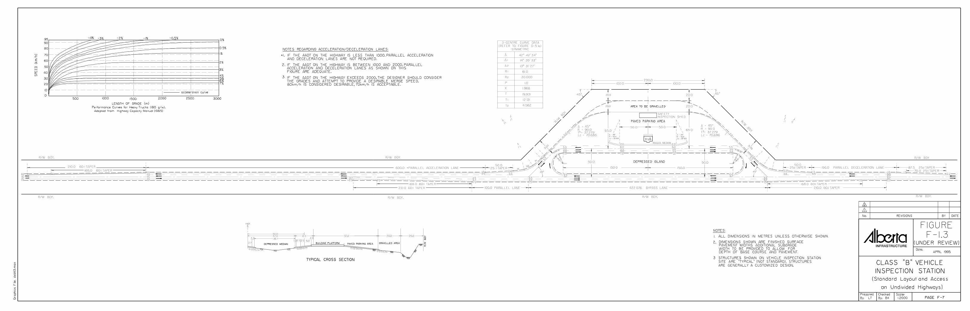
F.1.3 Class B VIS Class B is the standard vehicle inspection station for permanent, manned stations on two-lane undivided highways. This layout provides for some deceleration and acceleration of vehicles using the station, and it also provides a bypass lane for through traffic. The length of the parallel acceleration lane may be varied, depending on the level of service on the highway, and a range of lengths is suggested on the figure. The truck performance curves are also included for the designer's use.
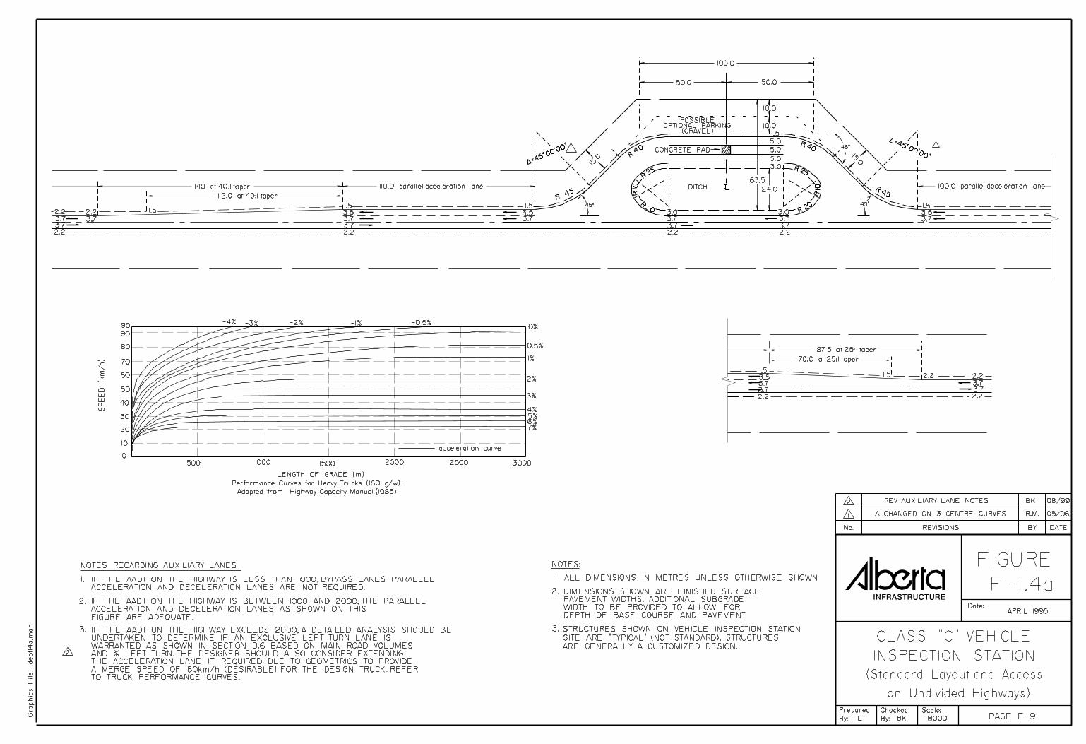
F.1.4 Class C Mobile VIS The Class C VIS is the standard layout for portable or mobile vehicle inspection stations. In recent years, some of these sites have been equipped with automatic weigh scales, which are normally unmanned and may be used by the public. The layout includes acceleration, deceleration and bypass lanes, the length of which depend on the traffic volume on the highway. Notes are included on Figures F-1.4a and F-1.4b as a guideline for provision of auxiliary lanes.

Alberta Infrastructure and Transporation HIGHWAY GEOMETRIC DESIGN GUIDE JANUARY 2008
ROADSIDE FACILITIES F-13
F.2 HIGHWAY SAFETY REST AREAS
F.2.1 Introduction Highway Safety Rest Areas (SRAs) are considered an integral part of North American highway systems. Alberta’s continuing priority of safe highways places emphasis on developing SRA networks to provide drivers safety, comfort and convenience. The concept of building a network of highway safety rest areas throughout the Alberta highway system is to address driver fatigue and reduce collisions. SRAs serve three primary purposes: 1. Improve safety by providing places for
travelers to periodically rest. For example, development of SRAs led to a 3.7% reduction in California collisions saving $148 million to society8.
2. Provide suitable places for emergency stops
and access to toilet facilities, telephones, etc., and
3. Satisfy the needs and operating legislated
requirements of the trucking and logging industries.
F.2.2 Strategic Framework F.2.2.1 Policy Document SRA development is addressed in the INFTRA consolidated 2004 SRA Policy Framework and Implementation Strategy, posted on the department webpage. The Highway Geometric Design Guide addresses what is to be done and to what standard.
8 August 2001 AASHTO Conference; Enhancing Highway Safety & Serving the Public: A Recommendation for Improving California’s Safety Roadside Rest Area System; Moore Iacofano Goltsman, Inc. Berkeley, CA; for CALTRANS; September 1999; P. 2.
The Framework is built around the historical research conducted by AASHTO9 and the resulting guidelines created by this organization. The Framework expects SRAs to be a part of the annual department regional budgeting process, constructed as separate projects or to be undertaken in conjunction with other major highway work in the vicinity. F.2.2.2 Location Specifications SRA’s are intended for use by all vehicles in one direction only and as such are built as couplets on both sides of designated highways and shall be offset by a minimum of one km. The near side access shall be located in advance of the far side SRA. Ideally, SRAs should be located near the top of smooth crest curves, provided that sight distance restrictions do not occur. This will aid the deceleration and acceleration of trucks or large recreational vehicles using the facility. F.2.2.3 Priority of Construction Priorities are specified in the 2004 Strategic Framework. “A” priorities are to be built first, then “B”, and finally “C”. A new SRA must be prioritized and ranked pursuant to the 2004 criteria before being considered for funding and construction.
F.2.3 Categories Alberta SRAs are divided into three categories based on the type and purpose of roadway served. 20-year projected AADT thresholds identify the typical SRA design. Where the addition of more through lanes to the highway is anticipated in less than 20-years, the access and egress layout to the SRA should be consistent with the future (wider) highway. 9 American Association of State Highway and Transportation Officials; Guide for Development of Rest Areas on Major Arterials and Freeways; Third Edition; ©2001; ISBN: 1-56051-151-6.
Alberta Infrastructure and Transporatation JANUARY 2008 HIGHWAY GEOMETRIC DESIGN GUIDE
ROADSIDE FACILITIES F-14
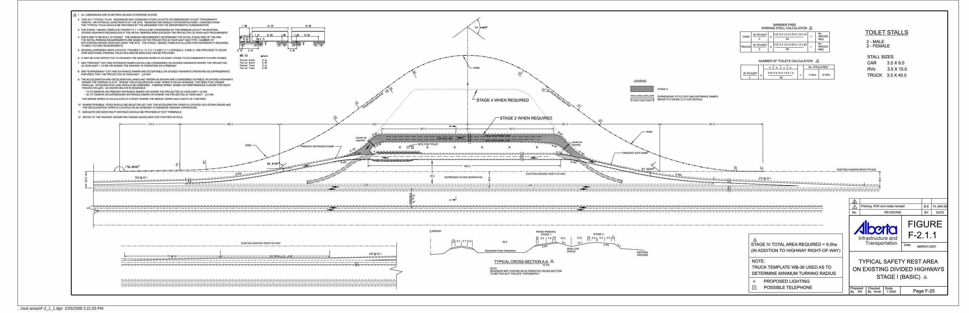
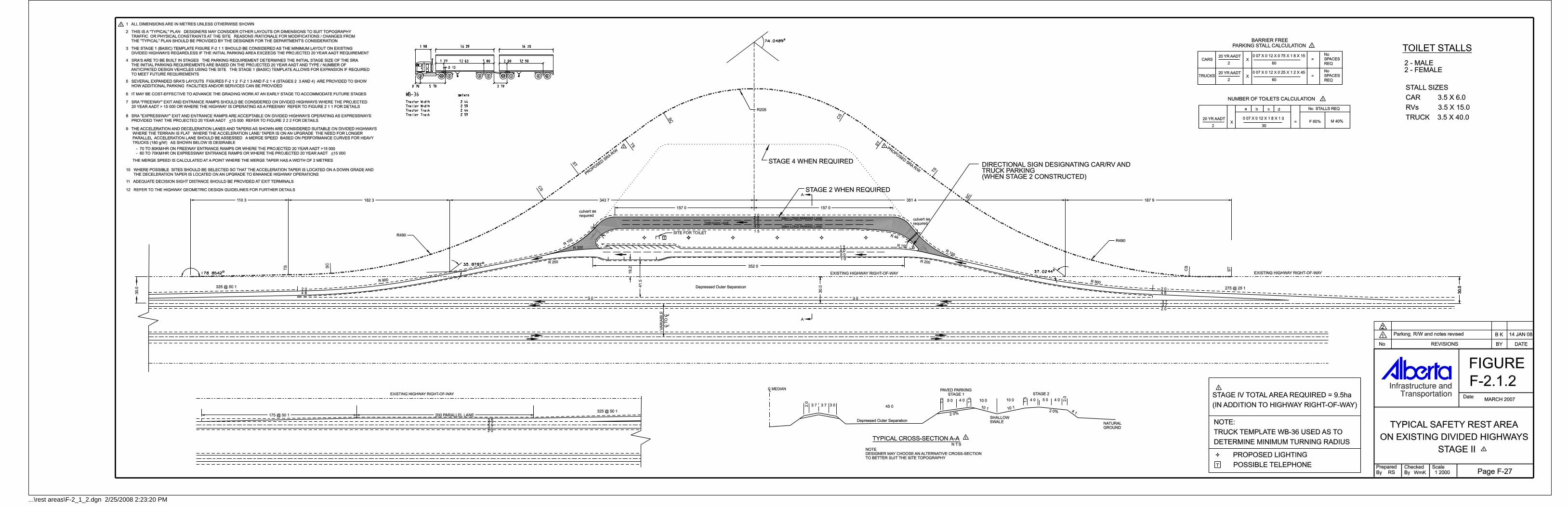
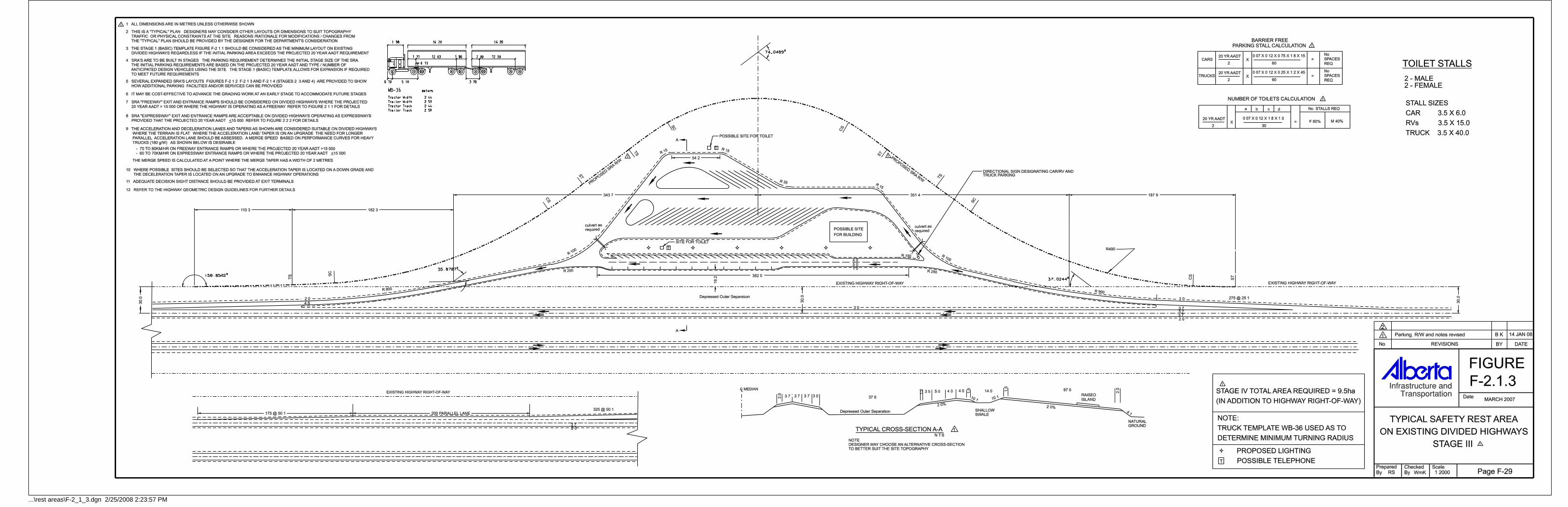
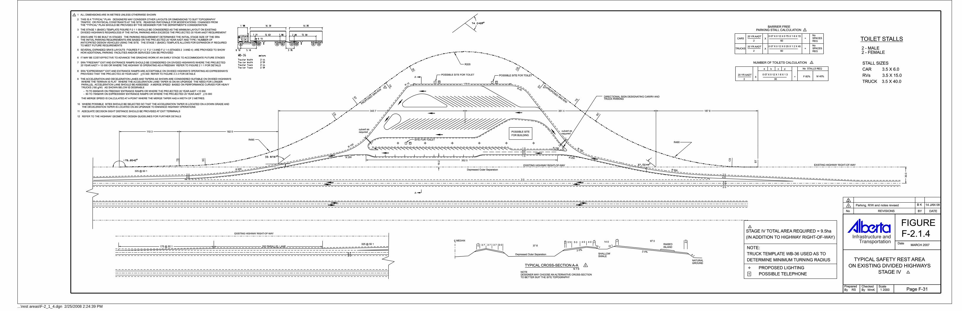
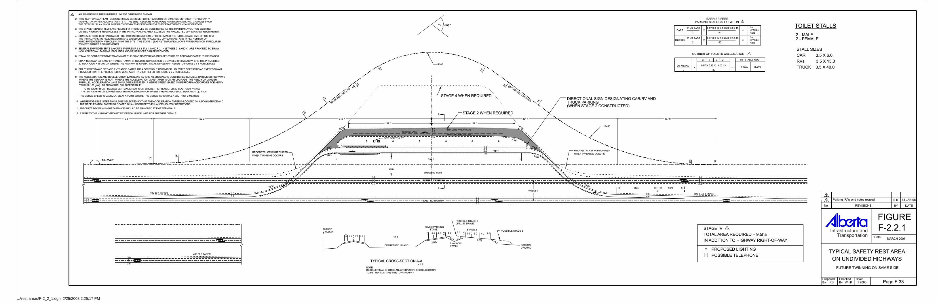
F.2.3.1 Existing Divided Highways This SRA accommodates all vehicle types and provides an outer separation between the site and the travel lanes. The following typical designs apply: Figure F-2.1.1: Stage I (Basic). Figure F-2.1.2: Stage II. Figure F-2.1.3: Stage III. Figure F-2.1.4: Stage IV. The Stage 1 (Basic) template Figure F-2.1.1 should be considered as the minimum layout on existing divided highways regardless if the initial parking area exceeds the projected 20 year AADT requirement. SRA’s are built in stages. The parking requirement determines the initial stage size of the SRA. The initial parking requirements are based on the projected 20 year AADT and type / number of anticipated design vehicles using the site. The Stage 1 (Basic) template allows for expansion if required to meet the future requirements. Refer to Section F.2.7 Parking Requirements for further details. Stages 2, 3, and 4 are provided to show how additional parking, facilities and/or services can be accommodated. SRA exit and entrance ramp configurations are based on 20 Year projected AADT AND highway classification. Refer to Section F.2.10 Exit and Entrance Requirements for further details. F.2.3.2 Future Divided Highways This SRA will accommodate all vehicle types and provide an outer separation between the site and the travel lanes. The design is configured to accommodate traffic from one travel direction only of an undivided highway, with provisions for easy modification when the highway is twinned into separate roadways in the future. Separate designs are provided to accommodate future expansion on either the same side or the opposite side of the existing undivided highway. The following typical designs apply:
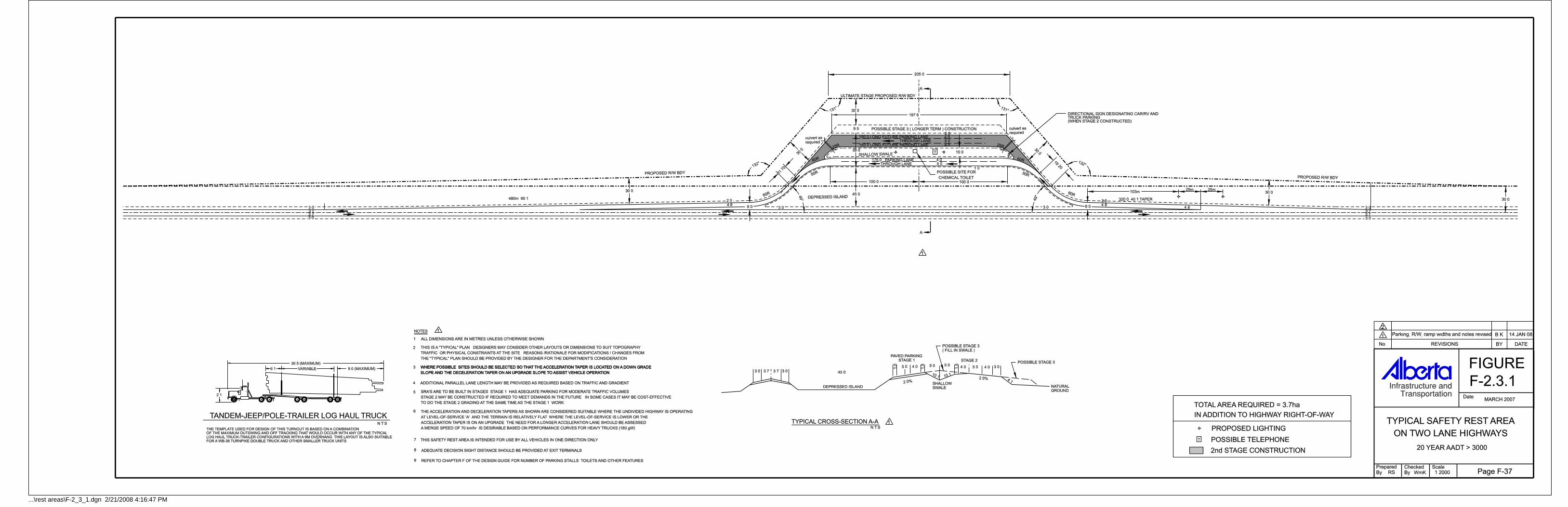
Figure F-2.2.1: Future Twinning on Same Side. Figure F-2.2.2: Future Twinning on Opposite Side. The parking requirement determines the initial stage size of the SRA. The initial parking requirements are based on the projected 20 year AADT and type / number of anticipated design vehicles using the site. The 20 Year projected AADT or highway classification determines the SRA exit and entrance ramp configurations also on future divided highways. F.2.3.3 Two Lane Highways SRA’s on two lane undivided highways are intended for use by all vehicles in one direction only. Refer to Section F.2.2.2 Location Specification for details. Accommodates basic parking located along undivided highways. Two typical layouts along with a design to accommodate log haul trucks are provided: Figure F-2.3.1: 20-year AADT > 3,000. Figure F-2.3.2: 20-year AADT < 3,000. Figure F-2.3.3: Log Haul Routes, 20-year AADT < 3,000 .
F.2.4 Spacing The spacing for SRAs is affected by traffic volume and the composition of the traffic stream. Ideally an overall travel time of 60 minutes between SRAs should be maintained with some concessions to topographical conditions and actual traffic mix /volumes along a particular route. Location Travel Time Between SRAs 60 minutes From Urban Areas 30 minutes The spacing of SRAs must also account for the combination of urban stops and rural commercial areas, which also afford motorists the opportunity to stop and rest. In general, approximately 30 minute travel time spacing from urban centres or previous stopping locations should be maintained depending on actual volumes and traffic composition.
Alberta Infrastructure and Transporation HIGHWAY GEOMETRIC DESIGN GUIDE JANUARY 2008
ROADSIDE FACILITIES F-15
In log haul areas, a stop is required within 80 kilometres of accessing a highway, therefore, the travel time could be extended beyond 30 minutes to meet this criteria. As SRAs are not intended to compete with existing highway services or commercial rest stops, only basic travel activities such as: driver fatigue break, checking loads and equipment, meeting trucking regulations, night time layovers, use of a toilet, making phone calls, picnic breaks, and litter disposal are to be accommodated at SRAs. Urban centres, commercial and private facilities meet higher levels of services and needs.
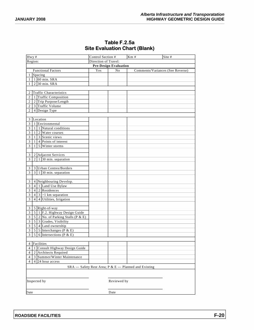
F.2.5 Site Evaluation Chart The SRA Site Evaluation Chart (Tables F.2.5a and F.2.5b following) provides a field reference guide to assess a specific location for a proposed SRA location and evaluates the SRA strategies and technical design location requirements. The evaluation must be done on-site because most of the strategic locations identified in the report were selected by a time and distance calculation and not confirmed by field observation. The site evaluator should review and comprehend the intent of how to locate SRAs, in accordance with the strategies identified, before undertaking the site evaluation work. Locating SRAs requires an assessment to ensure the best fit is achieved in relationship to the use of the highway, future interchanges, land acquisition potential, adjacent land uses and neighbouring communities. The site evaluation is a hierarchical assessment of key elements to determine final design parameters. The Evaluation Chart prompts the site evaluator to consider the following hierarchy of decisions:
Level 1 – Strategic Location • Determine spacing within the 60/30
minute travel times • 30 min. separation from urban centres • 30 min. spacing from private traveler
services
Level II – Site Utilization • Contemplate top of hill advantage • Utilize historic or scenic view
advantages • Develop location relative to
intersections or interchanges • Minimize adjacent neighbour conflicts • Minimize geotechnical &
environmental issues (soil conditions) • Consider ability to purchase land
Level III – Site Details • Applicable F.2 Design applied to site
characteristics • Couplet construction and minimum
one km stagger between SRAs on opposite sides of the highway
• Correlate size of site to projected traffic volumes and characteristics i.e. exit/entrance ramp and parking requirements
• Consider unique site construction challenges
• Identify site servicing issues • Respect Municipal land development
issues • Etc.
Use the checklist form following to conduct the specific site evaluations.
F.2.6 Typical Layout Design Formulas Typical SRA layouts are intended to provide consistency in SRA designs across the province, minimize the number of different designs, recognize highway AADT variances and to establish typical footprints to acquire land for right-of-ways. Typical layouts also orientate the user to similar conditions throughout the province. To develop typical designs, INFTRA has undertaken North American research over a number of years including AASHTO studies. To augment this research, INFTRA undertook a 24-hour vehicle parking count on March 27/28 2006 on Hwy #2 rest area and roadside turnouts south of Leduc (Control Sections 28 and 30). Based on this data, Alberta AADT statistics, Alberta VIS truck traffic counts, AASHTO
Alberta Infrastructure and Transporatation JANUARY 2008 HIGHWAY GEOMETRIC DESIGN GUIDE
ROADSIDE FACILITIES F-16
formulas for parking and facility calculations were modified or calibrated to create the formulas to match observed data (where deemed to be appropriate at this time) and Alberta conditions.
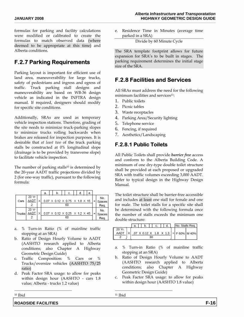
F.2.7 Parking Requirements Parking layout is important for efficient use of land area, maneuverability for large trucks, safety of pedestrians and ingress and egress of traffic. Truck parking stall designs and maneuverability are based on WB-36 design vehicle as indicated in the INFTRA design manual. If required, designers should modify for specific site conditions. Additionally, SRAs are used as temporary vehicle inspection stations. Therefore, grading of the site needs to minimize truck-parking slopes to minimize trucks rolling backwards when brakes are released for inspection purposes. It is desirable that at least two of the truck parking stalls be constructed at 0% longitudinal slope (drainage is to be provided by transverse slope) to facilitate vehicle inspection. The number of parking stalls10 is determined by the 20-year AADT traffic projections divided by 2 (for one-way traffic), pursuant to the following formula:
a. % Turn-in Ratio (% of mainline traffic
stopping at an SRA) b. Ratio of Design Hourly Volume to AADT
(AASHTO research applied to Alberta conditions; also Chapter A Highway Geometric Design Guide)
c. Traffic Composition: % Cars or % Trucks/oversize vehicles (AASHTO 75/25 ratio)
d. Peak Factor SRA usage: to allow for peaks within design hour (AASHTO - cars 1.8 value; Alberta - trucks 1.2 value)
10 Ibid
e. Residence Time in Minutes (average time parked in a SRA)
Divide by 60 Minute Cycle The SRA template footprint allows for future expansion for SRA’s to be built in stages. The parking requirement determines the initial stage size of the SRA.
F.2.8 Facilities and Services
All SRAs must address the need for the following minimum facilities and services11: 1. Public toilets 2. Picnic tables 3. Waste receptacles 4. Parking Area/Security lighting 5. Telephone service 6. Fencing, if required 7. Aesthetics/Landscaping F.2.8.1 Public Toilets All Public Toilets shall provide barrier free access and conform to the Alberta Building Code. A minimum of one dry-type double toilet structure shall be provided at each proposed or upgraded SRA with traffic volumes exceeding 3,000 AADT. Refer to typical design in the Highway Design Manual. The toilet structure shall be barrier-free accessible and includes at least one stall for female and one for male. The toilet stalls for a specific site shall be determined with the following formula once the number of stalls exceeds the minimum one double structure:
a. % Turn-in Ratio (% of mainline traffic
stopping at an SRA) b. Ratio of Design Hourly Volume to AADT
(AASHTO research applied to Alberta conditions; also Chapter A Highway Geometric Design Guide)
c. Peak Factor SRA usage: to allow for peaks within design hour (AASHTO 1.8 value)
11 Ibid
a. b. c. d. No. Stalls Req.20 Yr. AADT X .07 X 0.12 X 1.8 X 1.3 =
2M 40%F 60%
30
Alberta Infrastructure and Transporation HIGHWAY GEOMETRIC DESIGN GUIDE JANUARY 2008
ROADSIDE FACILITIES F-17
d. Users Per Vehicle (AASHTO guideline) Divide by 30 Users Per Hour
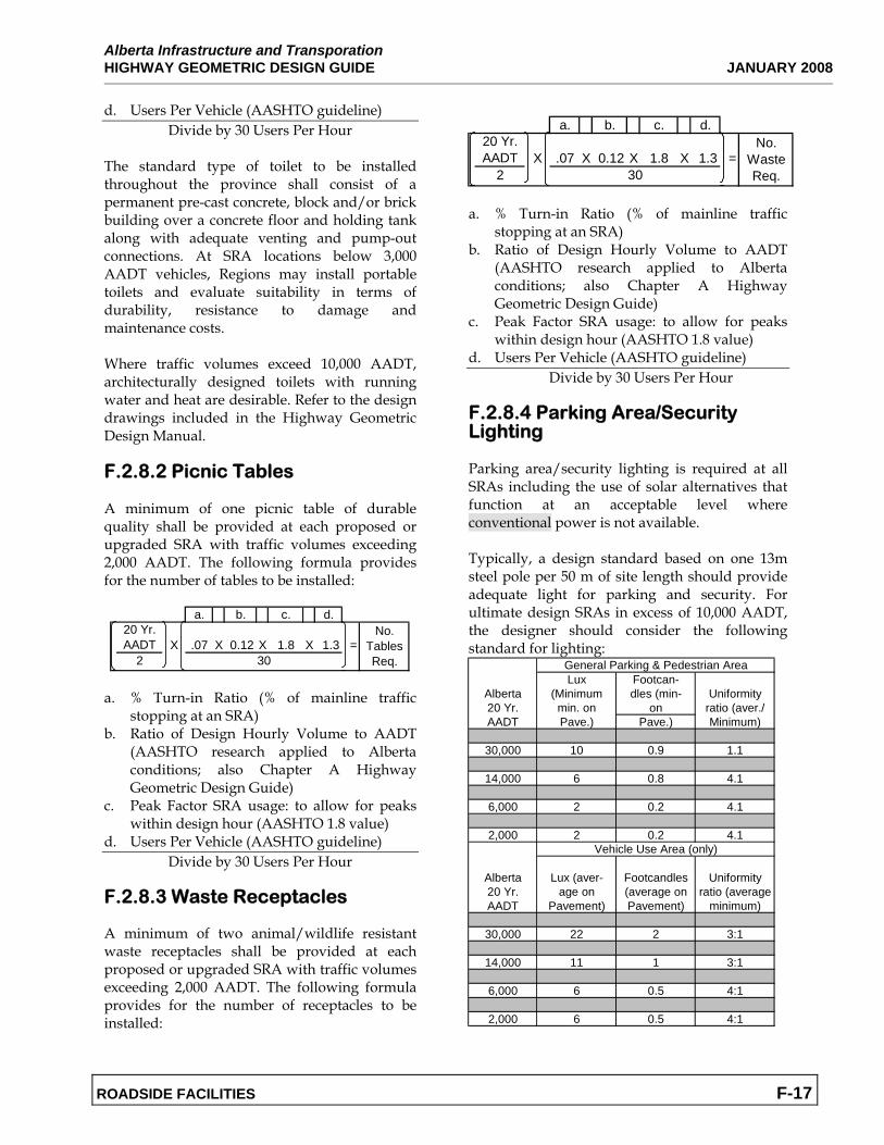
The standard type of toilet to be installed throughout the province shall consist of a permanent pre-cast concrete, block and/or brick building over a concrete floor and holding tank along with adequate venting and pump-out connections. At SRA locations below 3,000 AADT vehicles, Regions may install portable toilets and evaluate suitability in terms of durability, resistance to damage and maintenance costs. Where traffic volumes exceed 10,000 AADT, architecturally designed toilets with running water and heat are desirable. Refer to the design drawings included in the Highway Geometric Design Manual. F.2.8.2 Picnic Tables A minimum of one picnic table of durable quality shall be provided at each proposed or upgraded SRA with traffic volumes exceeding 2,000 AADT. The following formula provides for the number of tables to be installed:
a. % Turn-in Ratio (% of mainline traffic
stopping at an SRA) b. Ratio of Design Hourly Volume to AADT
(AASHTO research applied to Alberta conditions; also Chapter A Highway Geometric Design Guide)
c. Peak Factor SRA usage: to allow for peaks within design hour (AASHTO 1.8 value)
d. Users Per Vehicle (AASHTO guideline) Divide by 30 Users Per Hour
F.2.8.3 Waste Receptacles A minimum of two animal/wildlife resistant waste receptacles shall be provided at each proposed or upgraded SRA with traffic volumes exceeding 2,000 AADT. The following formula provides for the number of receptacles to be installed:
a. % Turn-in Ratio (% of mainline traffic
stopping at an SRA) b. Ratio of Design Hourly Volume to AADT
(AASHTO research applied to Alberta conditions; also Chapter A Highway Geometric Design Guide)
c. Peak Factor SRA usage: to allow for peaks within design hour (AASHTO 1.8 value)
d. Users Per Vehicle (AASHTO guideline) Divide by 30 Users Per Hour
F.2.8.4 Parking Area/Security Lighting Parking area/security lighting is required at all SRAs including the use of solar alternatives that function at an acceptable level where conventional power is not available. Typically, a design standard based on one 13m steel pole per 50 m of site length should provide adequate light for parking and security. For ultimate design SRAs in excess of 10,000 AADT, the designer should consider the following standard for lighting:
Lux Footcan-Alberta (Minimum dles (min- Uniformity20 Yr. min. on on ratio (aver./AADT Pave.) Pave.) Minimum)
30,000 10 0.9 1.1
14,000 6 0.8 4.1
6,000 2 0.2 4.1
2,000 2 0.2 4.1
Alberta Lux (aver- Footcandles Uniformity20 Yr. age on (average on ratio (averageAADT Pavement) Pavement) minimum)
30,000 22 2 3:1
14,000 11 1 3:1
6,000 6 0.5 4:1
2,000 6 0.5 4:1
General Parking & Pedestrian Area
Vehicle Use Area (only)
a. b. c. d.20 Yr. AADT X .07 X 0.12 X 1.8 X 1.3 =
2
No. Tables Req.30
a. b. c. d.20 Yr. AADT X .07 X 0.12 X 1.8 X 1.3 =
2
No. Waste Req.30
Alberta Infrastructure and Transporatation JANUARY 2008 HIGHWAY GEOMETRIC DESIGN GUIDE
ROADSIDE FACILITIES F-18
F.2.8.5 Telephones Telephones may be installed. F.2.8.6 Fencing Refer to Chapter C of Highway Geometric Design Guide for fencing requirements. Fencing may not be required if the highway is not fenced in the vicinity. Where public safety is an issue, appropriate fencing may be provided. Site conditions will determine the type of fence that needs to be installed. In some instances, replacement fencing may need to match adjacent landowner fencing. F.2.8.7 Aesthetics/Landscaping The appearance of a Divided Highway or Future Divided Highway SRA should follow three objectives: a. Blend in with the environment in which it is
located; b. Provide some shelter from sun and wind;
and c. Have some historical or regional quality that
will interest travelers. These objectives make SRAs more inviting to stop at and to stay longer, thereby reducing driving fatigue factors. It is suggested that a Landscape Architect be engaged to provide an appropriate design and to partner with other government departments (e.g. Agriculture, Community Development) to coordinate regional information points of interest, tourism, etc.
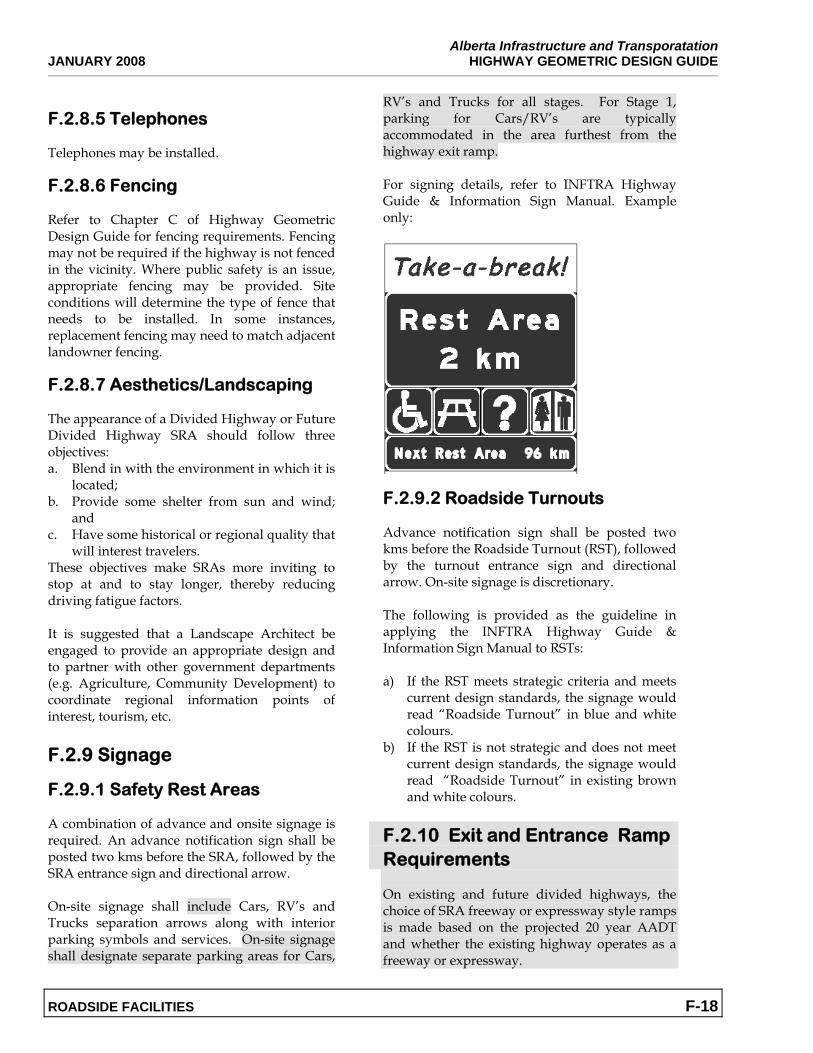
F.2.9 Signage F.2.9.1 Safety Rest Areas A combination of advance and onsite signage is required. An advance notification sign shall be posted two kms before the SRA, followed by the SRA entrance sign and directional arrow. On-site signage shall include Cars, RV’s and Trucks separation arrows along with interior parking symbols and services. On-site signage shall designate separate parking areas for Cars,
RV’s and Trucks for all stages. For Stage 1, parking for Cars/RV’s are typically accommodated in the area furthest from the highway exit ramp. For signing details, refer to INFTRA Highway Guide & Information Sign Manual. Example only:
F.2.9.2 Roadside Turnouts Advance notification sign shall be posted two kms before the Roadside Turnout (RST), followed by the turnout entrance sign and directional arrow. On-site signage is discretionary. The following is provided as the guideline in applying the INFTRA Highway Guide & Information Sign Manual to RSTs: a) If the RST meets strategic criteria and meets
current design standards, the signage would read “Roadside Turnout” in blue and white colours.
b) If the RST is not strategic and does not meet current design standards, the signage would read “Roadside Turnout” in existing brown and white colours.
F.2.10 Exit and Entrance Ramp Requirements On existing and future divided highways, the choice of SRA freeway or expressway style ramps is made based on the projected 20 year AADT and whether the existing highway operates as a freeway or expressway.
Alberta Infrastructure and Transporation HIGHWAY GEOMETRIC DESIGN GUIDE JANUARY 2008
ROADSIDE FACILITIES F-19
SRA freeway exit and entrance ramps should be considered on divided highways where the projected AADT > 15,000 (two-way traffic) OR where the highway is operating as a freeway. SRA expressway exit and entrance ramps are acceptable on divided highways where the projected AADT is ≤ 15,000 (two-way traffic) AND the highway is operating as an expressway. Acceleration and deceleration lanes and tapers shown for the freeway and expressway style ramps are considered suitable on divided highways where the terrain is flat. Deceleration requirements should be based on comfortable breaking rate of 0.25g (2.45m/s2) after the vehicle has typically left the trough lane. Where the acceleration lane/taper is on an upgrade, the need for longer parallel acceleration lane should be assessed. A merge speed based on performance curves for a heavy truck (180 g/W) as shown below is desirable: • 70 to 80 km/hr on freeway entrance ramps
or where the projected 20 year AADT > 15,000.
• 60 to 70 km/hr on expressway entrance ramps or where the projected 20 year AADT ≤ 15,000.
The merge speed is calculated at a point where the merge taper has a width of 2 metres. Adequate decision sight distance should also be provided at the SRA exit terminal.
End of Section.
Alberta Infrastructure and Transporatation JANUARY 2008 HIGHWAY GEOMETRIC DESIGN GUIDE
ROADSIDE FACILITIES F-20
Table F.2.5a Site Evaluation Chart (Blank)
Hwy # Control Section # Km # Site #Region: Direction of Travel:
Functional Factors Yes No Comments/Variances (See Reverse)1 Spacing1 1 60 min. SRA1 2 30 min. SRA
2 Traffic Characteristics2 1 Traffic Composition2 2 Trip Purpose/Length2 3 Traffic Volume2 4 Design Type
3 Location3 1 Environmental3 1 1 Natural conditions3 1 2 Water courses3 1 3 Scenic views3 1 4 Points of interest3 1 5 Winter storms
3 2 Adjacent Services3 2 1 30 min. separation
3 3 Urban Centres/Borders3 3 1 30 min. separation
3 4 Neighbouring Develop.3 4 1 Land Use Bylaw3 4 2 Residences3 4 3 >1 km separation3 4 4 Utilities, Irrigation
3 5 Right-of-way3 5 1 F.2. Highway Design Guide3 5 2 No. of Parking Stalls (P & E)3 5 3 Grades, Visibility3 5 4 Land ownership3 5 5 Interchanges (P & E)3 5 6 Intersections (P & E)
4 Facilities4 1 Consult Highway Design Guide4 2 Architects Required4 3 Summer/Winter Maintenance4 4 24 hour access
SRA — Safety Rest Area; P & E — Planned and Existing
Inspected by Reviewed by
Date Date
Pre-Design Evaluation
Alberta Infrastructure and Transporation HIGHWAY GEOMETRIC DESIGN GUIDE MARCH 2007
ROADSIDE FACILITIES F-21
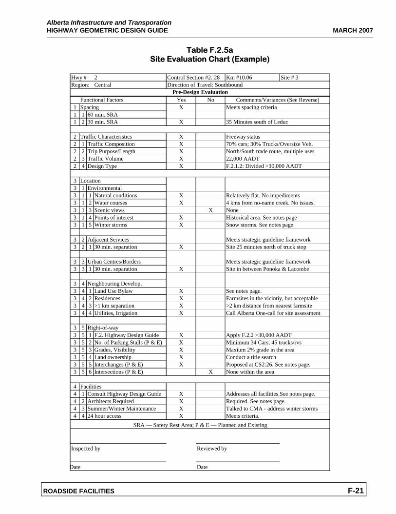
Table F.2.5a Site Evaluation Chart (Example)
Hwy # 2 Control Section #2.:28 Km #10.06 Site # 3Region: Central Direction of Travel: Southbound
Functional Factors Yes No Comments/Variances (See Reverse)1 Spacing X Meets spacing criteria1 1 60 min. SRA1 2 30 min. SRA X 35 Minutes south of Leduc
2 Traffic Characteristics X Freeway status2 1 Traffic Composition X 70% cars; 30% Trucks/Oversize Veh.2 2 Trip Purpose/Length X North/South trade route, multiple uses2 3 Traffic Volume X 22,000 AADT2 4 Design Type X F.2.1.2: Divided >30,000 AADT
3 Location3 1 Environmental3 1 1 Natural conditions X Relatively flat. No impediments3 1 2 Water courses X 4 kms from no-name creek. No issues.3 1 3 Scenic views X None3 1 4 Points of interest X Historical area. See notes page3 1 5 Winter storms X Snow storms. See notes page.
3 2 Adjacent Services Meets strategic guideline framework3 2 1 30 min. separation X Site 25 minutes north of truck stop
3 3 Urban Centres/Borders Meets strategic guideline framework3 3 1 30 min. separation X Site in between Ponoka & Lacombe
3 4 Neighbouring Develop.3 4 1 Land Use Bylaw X See notes page.3 4 2 Residences X Farmsites in the vicintiy, but acceptable3 4 3 >1 km separation X >2 km distance from nearest farmsite3 4 4 Utilities, Irrigation X Call Alberta One-call for site assessment
3 5 Right-of-way3 5 1 F.2. Highway Design Guide X Apply F.2.2 >30,000 AADT3 5 2 No. of Parking Stalls (P & E) X Minimum 34 Cars; 45 trucks/rvs 3 5 3 Grades, Visibility X Maxium 2% grade in the area3 5 4 Land ownership X Conduct a title search3 5 5 Interchanges (P & E) X Proposed at CS2:26. See notes page.3 5 6 Intersections (P & E) X None within the area
4 Facilities4 1 Consult Highway Design Guide X Addresses all facilities.See notes page.4 2 Architects Required X Required. See notes page.4 3 Summer/Winter Maintenance X Talked to CMA - address winter storms4 4 24 hour access X Meets criteria.
SRA — Safety Rest Area; P & E — Planned and Existing
Inspected by Reviewed by
Date Date
Pre-Design Evaluation
Alberta Infrastructure and Transporatation MARCH 2007 HIGHWAY GEOMETRIC DESIGN GUIDE
ROADSIDE FACILITIES F-22
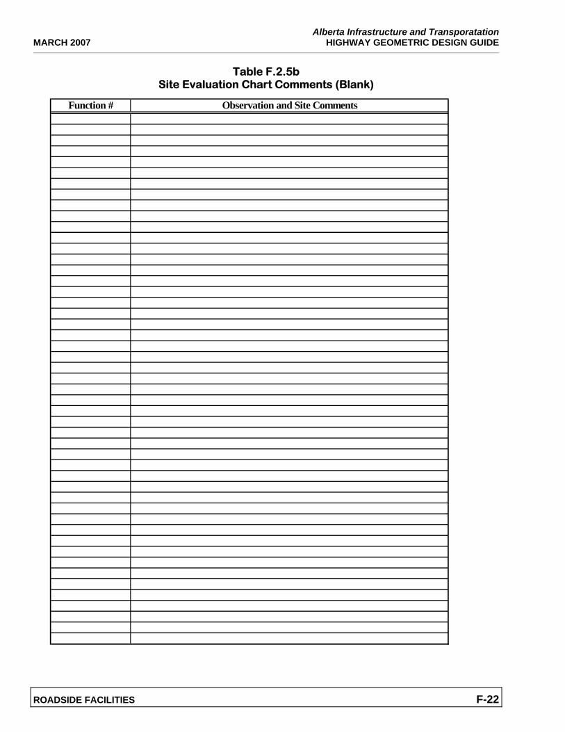
Table F.2.5b Site Evaluation Chart Comments (Blank)
Function # Observation and Site Comments
Alberta Infrastructure and Transporation HIGHWAY GEOMETRIC DESIGN GUIDE MARCH 2007
ROADSIDE FACILITIES F-23
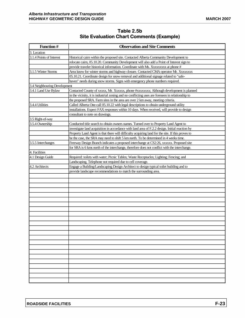
Table 2.5b Site Evaluation Chart Comments (Example)
Function # Observation and Site Comments3. Location3.1.4 Points of Interest Historical cairn within the proposed site. Contacted Alberta Community Development to
relocate cairn, 05.10.20. Community Development will also add a Point of Interest sign toprovide traveler historical information. Coordinate with Ms. Xxxxxxxxx at phone #
3.1.5 Winter Storms Area know for winter storms and highway closure. Contacted CMA operator Mr. Xxxxxxxx05.10.21. Coordinate design for snow removal and additional signage related to "safe-haven" needs during snow storms. Signs with emergency phone numbers required.
3.4 Neighbouring Development3.4.1 Land Use Bylaw Contacted County of xxxxx, Mr. Xxxxxx, phone #xxxxxxxx; Although development is planned
in the vicinity, it is industrial zoning and no conflicting uses are foreseen in relationship tothe proposed SRA. Farm sites in the area are over 2 km away, meeting criteria.
3.4.4 Utilities Called Alberta One-call 05.10.22 with legal descriptions to obtain underground utilityinstallations. Expect FAX responses within 10 days. When received, will provide to designconsultant to note on drawings.
3.5 Right-of-way3.5.4 Ownership Conducted title search to obtain owners names. Turned over to Property Land Agent to
investigate land acquisition in accordance with land area of F.2.2 design. Initial reaction byProperty Land Agent is that there will difficulty acquiring land for the site. If this proves tobe the case, the SRA may need to shift 5 km north. To be determined in 4 weeks time.
3.5.5 Interchanges Freeway Design Branch indicates a proposed interchange at CS2:26, xxxxxx. Proposed sitefor SRA is 6 kms north of the interchange, therefore does not conflict with the interchange.
4. Facilities4.1 Design Guide Required: toilets with water; Picnic Tables; Waste Receptacles; Lighting; Fencing; and
Landscaping. Telephone not required due to cell coverage.4.2 Architects Engage a Building/Landscaping Design Architect to design typical toilet building and to
provide landscape recommendations to match the surrounding area.
Alberta Infrastructure and Transporatation MARCH 2007 HIGHWAY GEOMETRIC DESIGN GUIDE
ROADSIDE FACILITIES F-24
This page left blank intentionally.
...\rest areas\F-2_1_1.dgn 2/25/2008 2:21:55 PM
...\rest areas\F-2_1_2.dgn 2/25/2008 2:23:20 PM
...\rest areas\F-2_1_3.dgn 2/25/2008 2:23:57 PM
...\rest areas\F-2_1_4.dgn 2/25/2008 2:24:39 PM
...\rest areas\F-2_2_1.dgn 2/25/2008 2:25:17 PM

...\rest areas\F-2_2_2.dgn 2/25/2008 2:25:58 PM
...\rest areas\F-2_3_1.dgn 2/21/2008 4:16:47 PM

Alberta Infrastructure and Transporatation MARCH 2007 HIGHWAY GEOMETRIC DESIGN GUIDE
F-40 ROADSIDE FACILITIES
This page left blank intentionally.

Alberta Infrastructure and Transporatation MARCH 2007 HIGHWAY GEOMETRIC DESIGN GUIDE
F-42 ROADSIDE FACILITIES
This page left blank intentionally.
Alberta Infrastructure and Transportation HIGHWAY GEOMETRIC DESIGN GUIDE MARCH 2007
ROADSIDE FACILITIES F-43
F.3 ROADSIDE TURNOUTS FOR HIGHLOAD / WIDELOAD OVERSIZE USE Figure 3.1 illustrates the typical design for roadside turnouts on Highload/Wideload Oversize Routes (near point of origin) on undivided highways. While all vehicles are not prohibited from using these turnouts, they are a special layout and are only required at locations that are frequently used as “waiting areas” near the point of origin for trucks carrying high/wide oversized loads. These locations are generally outside of major urban and industrial centres. Acceleration/deceleration lanes are not required for high/wide oversize loads due to the special traffic arrangements used for movement of these loads.
Alberta Infrastructure and Transporatation MARCH 2007 HIGHWAY GEOMETRIC DESIGN GUIDE
F-44 ROADSIDE FACILITIES
This page left blank intentionally.


![DITCM Roadside Facilities for Cooperative Systems Testing and … · Integrated Test Site for Cooperative Mobility [1]. DITCM operates an extensive set of facilities, including simulation](https://img.pdfslide.net/doc/110x75/5ffc7335e4c8cc25fb0befd1/ditcm-roadside-facilities-for-cooperative-systems-testing-and-integrated-test-site.jpg)
![Rest Areas and Roadside Facilities Maintenance [Location] [Date] Weeds and Roads D. PolsterJ. Leekie BC MoT](https://img.pdfslide.net/doc/110x75/5516c243550346f6208b58b7/rest-areas-and-roadside-facilities-maintenance-location-date-weeds-and-roads-d-polsterj-leekie-bc-mot.jpg)